Embed Size (px)
Citation preview
National Plumbing Codeof Canada 1995
First Revisions and Errata
Issued by the Canadian Commission onBuilding and Fire Codes
August 1999
The attached pages identify revisions and errata to theNational Plumbing Code of Canada 1995. Simply replace the currentpage in your document with the updated page provided.
The revisions have been approved by the Canadian Commission onBuilding and Fire Codes. The revisions contained herein includeupdates to 30 June 1997.
The errata are corrections that have been identified and areincluded to facilitate the use of the Code.
Revisions are identified by an r in the margin; errata are identifiedby an e.

NPC 1995 First Revisions and Errata
1.3.2.(1)Combustible
6.2.4.(1)
Noncombustible1.3.3.(1)1.9.2.(1)Table 1.9.3.
2.2.2.(7)
6.2.12.(2)
2.5.1.(1)(a)2.5.1.(2)(a)&(b)2.5.2.(1)2.5.5.(1)2.5.6.(1)2.5.7.(2)(a)&(b)
2.5.10.(1)(a)-(e)&(g)2.5.11.(1)(a)&(b)2.5.12.(1)(a)-(c)2.5.15.(1)2.6.1.(1)2.6.4.(1)2.6.4.(2)2.8.1.(1)(a)&(b)2.10.12.(1)
4.6.4.(1)-(6)
6.3.4.(1)
Figure A-1.6.4.Table A-1.9.3.
Table A-2.5., A-2.6. and A-2.7.A-2.5.6.(1)
Figure A-3.3.10.
A-4.4.3.(1)
A-4.6.4.(6)A-4.10.4.(1)
Figure A-5.2.1.Figure A-5.8.Table A-5.8.A.Table A-5.8.B.
A-6.1.1.(1)Figure A-6.1.1.B.A-6.1.11.A-6.2.4.
2.5.8.(1)
Figure A-4.6.4.

Section 1General Requirements andAdministration
1.1. Application1.1.1. General
1) This Code applies to the design,construction, extension, alteration, renewal or repairof plumbing systems.
1.1.2. Administrative Requirements
1) The appropriate requirements in the Ad-ministrative Requirements for Use with the NationalBuilding Code 1995 shall apply to this Code.
1.2. Scope1.2.1. Scope
1) This Code specifies the minimum re-quirements for
a) drainage systems for water-borne wastesand storm water for buildings to the pointof connection with public services,
b) venting systems,c) water service pipes, andd) water distribution systems.
1.3. Definitions andAbbreviations
1.3.1. Definitions Not Listed
1) Definitions of words and phrases used inthis Code that are not included in the list of defini-tions in this Section shall have the meanings whichare commonly assigned to them in the context inwhich they are used in this Code, taking into ac-count the specialized use of terms by the varioustrades and professions to which the terminology ap-plies.
1.3.2. Definitions in Italics
1) The words and terms in italics in thisCode shall have the following meanings:
Air break means the unobstructed vertical distancebetween the lowest point of an indirectly connectedsoil-or-waste pipe and the flood level rim of the fix-ture into which it discharges. (See A-3.3.12.(2) inAppendix A.)
Air gap means the unobstructed vertical distancethrough air between the lowest point of a watersupply outlet and the flood level rim of the fixtureor device into which the outlet discharges. (SeeA-6.2.9. in Appendix A.)
Alloyed zinc means an alloy of zinc having the corro-sion resistance and physical properties of analloy containing 0.15% titanium, 0.74% copperand 99.11% zinc, and so tempered as to be capa-ble of being formed into the shape required for awatertight joint.
Backflow means a flowing back or reversal of thenormal direction of the flow.
Backflow preventer means a device or a method thatprevents backflow. (See Appendix A.)
Back pressure means pressure higher than the supplypressure.
Back-siphonage means backflow caused by a negativepressure in the supply system. (See Appendix A.)
Back-siphonage preventer (or vacuum breaker) means adevice or a method that prevents back-siphonage.(See Appendix A.)
Backwater valve means a check valve designed for usein a gravity drainage system.
Branch means a soil-or-waste pipe connected at itsupstream end to the junction of 2 or more soil-or-waste pipes or to a soil-or-waste stack, andconnected at its downstream end to anotherbranch, a sump, a soil-or-waste stack or a buildingdrain. (See A-1.3.2. Drainage System in Appen-dix A.)
Branch vent means a vent pipe that is connected at itslower end to the junction of 2 or more vent pipesand is connected at its upper end either to a stack
An asterisk (*) following a defined word or term meansthat the definition for that word or term is taken from theNational Building Code of Canada 1995.
1

1.3.2.
vent, vent stack or header, or is terminated in openair. (See Appendix A.)
Building* means any structure used or intended forsupporting or sheltering any use or occupancy.
Building drain means the horizontal piping, includ-ing any vertical offset that conducts sewage,clear-water waste or storm water to a building sewer.(See A-1.3.2. Drainage System in Appendix A.)
Building sewer means a pipe that is connected to abuilding drain 1 m outside a wall of a building andthat leads to a public sewer or private sewage dis-posal system.
Building trap means a trap that is installed in abuilding drain or building sewer to prevent circula-tion of air between a drainage system and a publicsewer. (See A-4.5.4.(1) in Appendix A.)
Check valve means a valve that permits flow in onedirection but prevents a return flow.
Cleanout means an access provided in drainage andventing systems to provide for cleaning and in-spection services.
Clear-water waste means waste water with impuritylevels that will not be harmful to health and mayinclude cooling water and condensate drainagefrom refrigeration and air conditioning equip-ment and cooled condensate from steam heatingsystems, but does not include storm water. (SeeAppendix A.)
Combined building drain means a building drain that isintended to conduct sewage and storm water.
Combined building sewer means a building sewer thatis intended to conduct sewage and storm water.
Combined sewer means a sewer that is intended toconduct sewage and storm water.
Combustible* means that a material fails to meet theacceptance criteria of CAN4-S114-M,
e “Test for Determination of Non-Combustibility in Building Materials.”
Continuous vent means a vent pipe that serves 2 ormore fixtures and is an extension of a wet vent.(See Appendix A.)
Critical level means the level of submergence atwhich the back-siphonage preventer ceases to pre-vent back-siphonage.
Dead end means a pipe that terminates with a closedfitting.
Developed length means the length along the centreline of the pipe and fittings. (See A-5.6.3.(1) inAppendix A.)
Directly connected means physically connected insuch a way that water or gas cannot escape fromthe connection.
Drainage system means an assembly of pipes, fit-tings, fixtures, traps and appurtenances that is
used to convey sewage, clear-water waste or stormwater to a public sewer or a private sewage disposalsystem, but does not include subsoil drainage pipes.(See Appendix A.)
Dual vent means a vent pipe that serves 2 fixtures andconnects at the junction of the trap arms. (See A-1.3.2. Drainage System in Appendix A.)
Dwelling unit* means a suite operated as a house-keeping unit used or intended to be used as adomicile by one or more persons and usuallycontaining cooking, eating, living, sleeping andsanitary facilities.
Fire separation* means a construction assembly thatacts as a barrier against the spread of fire.
Fixture means a receptacle, appliance, apparatus orother device that discharges sewage or clear-waterwaste, and includes a floor drain.
Fixture drain means the pipe that connects a trapserving a fixture to another part of a drainage sys-tem.
Fixture outlet pipe means a pipe that connects thewaste opening of a fixture to the trap serving thefixture. (See Appendix A.)
Fixture unit (as applying to drainage systems) meansthe unit of measure based on the rate of dis-charge, time of operation and frequency of use ofa fixture that expresses the hydraulic load that isimposed by that fixture on the drainage system.
Fixture unit (as applying to water distribution systems)means the unit of measure based on the rate ofsupply, time of operation and frequency of use ofa fixture or outlet that expresses the hydraulicload that is imposed by that fixture or outlet onthe supply system.
Flood level rim means the top edge at which watercan overflow from a fixture or device. (See A-1.3.2. Back Siphonage in Appendix A.)
Flow control roof drain means a roof drain that re-stricts the flow of storm water into the stormdrainage system.
Fresh air inlet means a vent pipe that is installed inconjunction with a building trap and terminatesoutdoors. (See A-4.5.4.(1) in Appendix A.)
Header means a vent pipe that connects 2 or morevent stacks or stack vents to outdoors. (See Appen-dix A.)
Indirect service water heater* means a service waterheater that derives its heat from a heatingmedium such as warm air, steam or hot water.
Indirectly connected means not directly connected. (SeeA-3.3.12.(2) in Appendix A.)
Individual vent means a vent pipe that serves one fix-ture.
2

1.3.2.
Interceptor means a receptacle that is installed toprevent oil, grease, sand or other materials frompassing into a drainage system.
Leader means a pipe that is installed to carry stormwater from a roof to a storm building drain or seweror other place of disposal.
Nominally horizontal means at an angle of less than45� with the horizontal. (See Appendix A.)
Nominally vertical means at an angle of not morethan 45� with the vertical. (See Appendix A.)
Noncombustible* means that a material meets thee acceptance criteria of CAN4-S114-M, “Test
for Determination of Non-Combustibilityin Building Materials.”
Occupancy* means the use or intended use of abuilding or part thereof for the shelter or supportof persons, animals or property.
Offset means the piping that connects the ends of 2pipes that are parallel. (See Appendix A.)
Owner* means any person, firm or corporation con-trolling the property under consideration.
Plumbing contractor means a person, corporation orfirm that undertakes to construct, extend, alter,renew or repair any part of a plumbing system.
Plumbing system* means a drainage system, a ventingsystem and a water system or parts thereof. (SeeAppendix A.)
Potable means safe for human consumption.
Private sewage disposal system* means a privatelyowned plant for the treatment and disposal ofsewage (such as a septic tank with an absorptionfield).
Private use (as applying to the classification ofplumbing fixtures) means fixtures in residencesand apartments, in private bathrooms of hotels,and in similar installations in other buildings forone family or an individual.
Private water supply system means an assembly ofpipes, fittings, valves, equipment and appurte-nances that supplies water from a private sourceto a water distribution system.
Public use (as applying to the classification ofplumbing fixtures) means fixtures in generalwashrooms of schools, gymnasiums, hotels, bars,public comfort stations and other installationswhere fixtures are installed so that their use is un-restricted.
Relief vent means an auxiliary vent which providesadditional circulation of air between drainage sys-tems and venting systems.
Riser means a water distribution pipe that extendsthrough at least one full storey.
Roof drain means a fitting or device that is installedin the roof to permit storm water to discharge intoa leader.
Roof gutter means an exterior channel installed atthe base of a sloped roof to convey storm water.
Sanitary building drain means a building drain thatconducts sewage.
Sanitary building sewer means a building sewer thatconducts sewage.
Sanitary drainage system* means a drainage systemthat conducts sewage.
Sanitary sewer means a sewer that conducts sewage.
Service water heater* means a device for heating wa-ter for plumbing services.
Sewage means any liquid waste other than clear-water waste or storm water.
Size means the nominal diameter by which a pipe,fitting, trap or other similar item is commerciallydesignated.
Soil-or-waste pipe or waste pipe means a pipe in a san-itary drainage system.
Soil-or-waste stack means a vertical soil-or-waste pipethat passes through one or more storeys, and in-cludes any offset that is part of the stack.
Stack vent means a vent pipe that connects the top ofa soil-or-waste stack to a header or open air. (See A-1.3.2. Drainage System in Appendix A.)
Storage-type service water heater* means a service waterheater with an integral hot water storage tank.
Storey (as applying to plumbing) means the intervalbetween 2 successive floor levels, including mez-zanine floors that contain plumbing fixtures, orbetween a floor level and roof.
Storm building drain means a building drain that con-veys storm water.
Storm building sewer means a building sewer that con-veys storm water.
Storm drainage system means a drainage system thatconveys storm water.
Storm sewer means a sewer that conveys storm water.
Storm water means water that is discharged from asurface as a result of rainfall or snowfall.
Subdrainage system means a drainage system that doesnot drain by gravity to the building sewer.
Subsoil drainage pipe means a pipe that is installedunderground to intercept and convey subsurfacewater.
Suite* means a single room or series of rooms ofcomplementary use, operated under a single ten-ancy and includes dwelling units, individual guest
3

1.3.2.
rooms in motels, hotels, boarding houses, room-ing houses and dormitories, as well as individualstores and individual or complementary roomsfor business and personal services occupancies.
Trap means a fitting or device that is designed tohold a liquid seal that will prevent the passage ofgas but will not materially affect the flow of a liq-uid.
Trap arm means that portion of a fixture drain be-tween the trap weir and the vent pipe fitting. (SeeA-5.6.3.(1) in Appendix A.)
Trap dip means the lowest part of the upper interiorsurface of a trap.
Trap seal depth means the vertical distance betweenthe trap dip and the trap weir. (See A-2.3.1.(1) inAppendix A.)
Trap standard means the trap for a fixture that is inte-gral with the support for the fixture.
Trap weir means the highest part of the lower inte-rior surface of a trap. (See A-2.3.1.(1) and (3) inAppendix A.)
Vacuum breaker (see back-siphonage preventer).
Vent pipe means a pipe that is part of a venting sys-tem.
Vent stack means a vent pipe that is connected at itsupper end to a header or is terminated in open airand that is used to limit pressure differential in asoil-or-waste stack. (See A-1.3.2. Drainage Systemin Appendix A.)
Venting system means an assembly of pipes and fit-tings that connects a drainage system with outsideair for circulation of air and the protection of trapseals in the drainage system. (See A-1.3.2. DrainageSystem in Appendix A.)
Waste pipe (see soil-or-waste pipe).
Water distribution system means an assembly ofpipes, fittings, valves and appurtenances thatconveys water from the water service pipe or pri-vate water supply system to water supply outlets,fixtures, appliances and devices.
11 Laurier Street, Hull, Quebec,Water service pipe means a pipe that conveys water
from a public water main or private water sourceto the inside of the building.
Water system means a private water supply system, awater service pipe, a water distribution system orparts thereof.
Wet vent means a soil-or-waste pipe that also servesas a vent pipe. (See A-5.8.1. in Appendix A.)
1.3.3. Abbreviations of Proper Names
1) Abbreviations of proper names in thisCode have the following meanings:
AES...................Atmospheric Environment Service(Environment Canada, 4905Dufferin Street, Downsview,Ontario, M3H 5T4)
ANSI.................American National StandardsInstitute (11 West 42nd Street, 13thFloor, New York, New York 10036U.S.A.)
ASHRAE..........American Society of Heating,Refrigerating and Air-ConditioningEngineers (1791 Tullie Circle, N.E.,Atlanta, Georgia 30329 U.S.A.)
ASPE.................American Society of PlumbingEngineers (3617 Thousand OaksBlvd., Suite 210, West Lake Village,California 91362 U.S.A.)
ASTM................American Society for Testing andMaterials (100 Barr Harbor Dr.,West Conshohocken, Pennsylvania19428 U.S.A.)
AWWA.............American Water Works Association(6666 West Quincy Avenue, Denver,Colorado 80235 U.S.A.)
CAN..................National Standard of Canadadesignation (The number or namefollowing the CAN designationrepresents the agency under whoseauspices the standard is issued.CAN 1 designates CGA,CAN 2 designates CGSB,CAN 3 designates CSA, andCAN 4 designates ULC.)
CCBFC..............Canadian Commission on Buildingand Fire Codes (National ResearchCouncil of Canada, Ottawa, OntarioKlA 0R6)
CGA..................Canadian Gas Association r(International Approval Services)Now Part of CSA. See CSA.
CGSB.................Canadian General Standards Board r(Place du Portage, Phase III, 6B1
K1A 1G6)CSA...................Canadian Standards Association
(178 Rexdale Blvd., Etobicoke,Ontario M9W 1R3)
NBC.................. National Building Code of Canada(National Research Council ofCanada, Ottawa, Ontario KlA 0R6)
NFPA................National Fire Protection Association(Batterymarch Park, Quincy,Massachusets 02269 U.S.A.)
ULC...................Underwriters’ Laboratories ofCanada (7 Crouse Road,Scarborough, Ontario M1R 3A9)
4
1.6.4.
1.3.4. Symbols and Other Abbreviations
1) Symbols and other abbreviations in thisCode have the following meanings:
ABS ................. acrylonitrile-butadiene-styreneAL .................. aluminumcm2 .................. square centimetre(s)CPVC.............. chlorinated poly (vinyl chloride)�........................ degree(s)�C..................... degree(s) Celsiusdiam................ diameterDWV............... drain, waste and venth....................... hour(s)in...................... inch(es)kg/m2 ............. kilograms per square metrekPa .................. kilopascal(s)L ..................... litre(s)L/s................... litres per secondm...................... metre(s)m2.................... square metre(s)max.................. maximummin.................. minimummin.................. minute(s)mm.................. millimetre(s)NA................... not applicableNo.................... number(s)PE.................... polyethylenePEX.................. crosslinked polyethylenePP-R................ polypropylenePVC................. poly (vinyl chloride)temp................ temperature1 in 50............. slope of 1 vertical to 50 horizontal
1.4. Equivalents1.4.1. Alternate Materials, Appliances,
Systems and Equipment
1) The provisions of this Code are not in-tended to limit the appropriate use of materials,appliances, systems, equipment, methods of designor construction procedures not specifically author-ized herein.
1.4.2. Evidence of EquivalentPerformance
1) Any person desirous of providing anequivalent to satisfy one or more of the require-ments of this Code shall submit sufficient evidenceto demonstrate that the proposed equivalent willprovide the level of performance required by thisCode.
1.4.3. Equivalence Demonstrated byPast Performance, Test orEvaluation
1) Materials, appliances, systems, equip-ment, methods of design and constructionprocedures not specifically described herein, orwhich vary from the specific requirements in thisCode, may be used if it can be shown that thesealternatives are suitable on the basis of past perfor-mance, tests or evaluations.
1.5. Plumbing Facilities
1.5.1. Provision in Accordance with NBC
1) Plumbing facilities shall be provided inaccordance with Subsection 3.7.4. of Part 3 andSection 9.31. of Part 9 of the National Building Codeof Canada 1995.
1.6. ServiceConnections
1.6.1. Sanitary Drainage Systems
1) Every sanitary drainage system shall beconnected to a public sanitary sewer, a public com-bined sewer or a private sewage disposal system.
2) A combined building drain shall not be in-stalled. (See Appendix A.)
1.6.2. Storm Drainage Systems
1) Every storm drainage system shall be con-nected to a public storm sewer, a public combinedsewer or a designated storm water disposal location.
1.6.3. Water Distribution Systems
1) Every water distribution system shall beconnected to a public water main or a private potablewater supply system.
1.6.4. Separate Services
1) Piping in any building connected to thepublic services shall be connected separately frompiping of any other building, except that an ancillarybuilding on the same property may be served by thesame service. (See Appendix A.)
5
1.7.
1.7. Location of Fixtures1.7.1. Lighting and Ventilation
Requirements
1) Plumbing fixtures shall not be installed ina room that is not lighted and ventilated in accor-dance with the appropriate requirements in Parts 3and 9 of the National Building Code of Canada 1995.
1.7.2. Accessibility
1) Every fixture, appliance, interceptor,cleanout, valve, device or piece of equipment shallbe so located that it is readily accessible for use,cleaning and maintenance.
1.8. Plumbing Drawingsand RelatedDocuments
1.8.1. Contents
1) Plumbing drawings and related docu-ments submitted with the application for aplumbing permit shall show
a) the location and size of every buildingdrain and of every trap and cleanout fit-ting that is on a building drain,
b) the size and location of every soil-or-wastepipe, trap and vent pipe, and
c) a layout of the potable water distributionsystem, including pipe sizes and valves.
1.9. ReferencedDocuments
1.9.1. Conflict between Code andReferenced Documents
1) In case of conflict between the provisionsof this Code and those of a referenced document,the provisions of this Code shall govern.
1.9.2. Amendments, Revisions andSupplements
1) Unless otherwise specified herein, thedocuments referenced in this Code shall include allamendments, revisions and supplements effective to30 June 1997. r
1.9.3. Designated Editions
1) Where standards are referenced in thisCode, they shall be the editions designated in Table1.9.3.
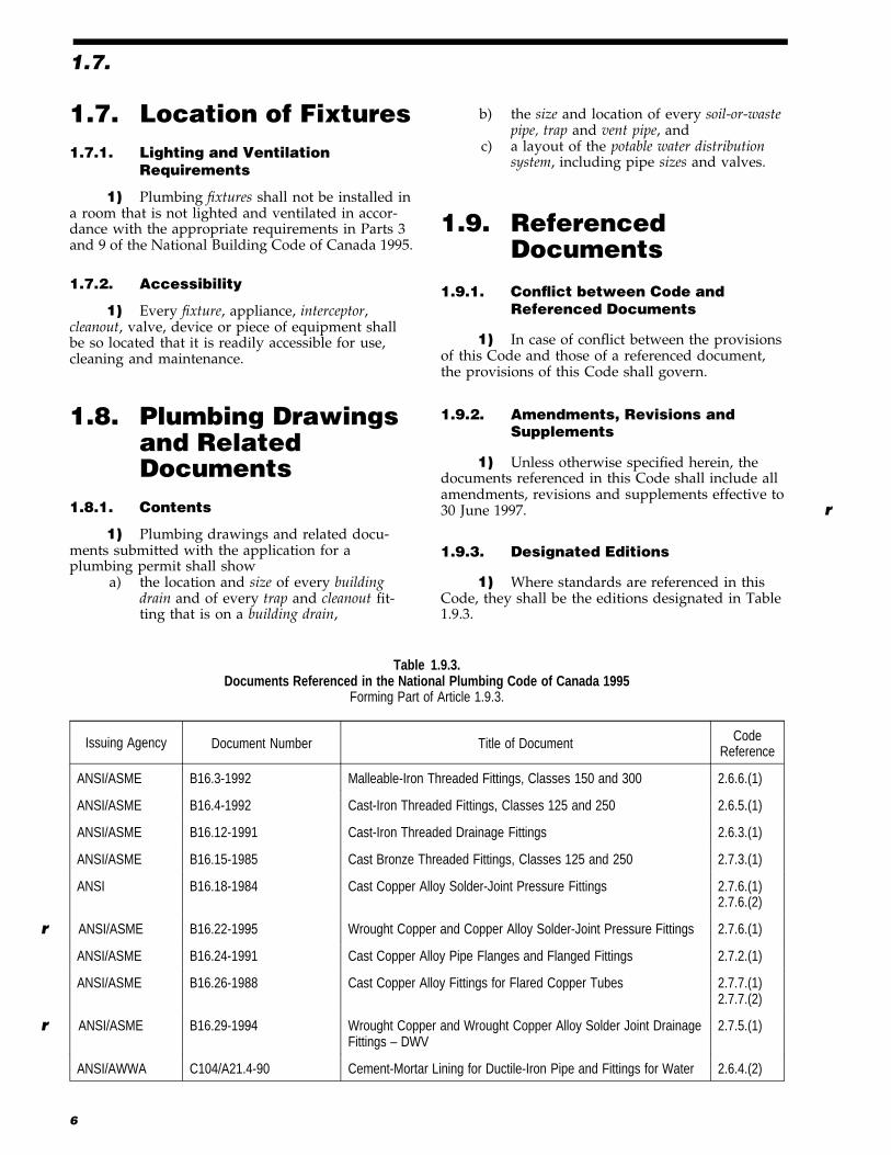
Table 1.9.3.Documents Referenced in the National Plumbing Code of Canada 1995
Forming Part of Article 1.9.3.
Issuing Agency Document Number Title of Document CodeReference
ANSI/ASME B16.3-1992 Malleable-Iron Threaded Fittings, Classes 150 and 300 2.6.6.(1)
ANSI/ASME B16.4-1992 Cast-Iron Threaded Fittings, Classes 125 and 250 2.6.5.(1)
ANSI/ASME B16.12-1991 Cast-Iron Threaded Drainage Fittings 2.6.3.(1)
ANSI/ASME B16.15-1985 Cast Bronze Threaded Fittings, Classes 125 and 250 2.7.3.(1)
ANSI B16.18-1984 Cast Copper Alloy Solder-Joint Pressure Fittings 2.7.6.(1)2.7.6.(2)
r ANSI/ASME B16.22-1995 Wrought Copper and Copper Alloy Solder-Joint Pressure Fittings 2.7.6.(1)
ANSI/ASME B16.24-1991 Cast Copper Alloy Pipe Flanges and Flanged Fittings 2.7.2.(1)
ANSI/ASME B16.26-1988 Cast Copper Alloy Fittings for Flared Copper Tubes 2.7.7.(1)2.7.7.(2)
r ANSI/ASME B16.29-1994 Wrought Copper and Wrought Copper Alloy Solder-Joint DrainageFittings – DWV
2.7.5.(1)
ANSI/AWWA C104/A21.4-90 Cement-Mortar Lining for Ductile-Iron Pipe and Fittings for Water 2.6.4.(2)
6

1.9.3.
Table 1.9.3. (Continued)
Issuing Agency Document Number Title of Document CodeReference
ANSI/AWWA C110/A21.10-93 Ductile-Iron and Gray-Iron Fittings, 3 in. Through 48 in., for Waterand Other Liquids
2.6.4.(3)
r ANSI/AWWA C111/A21.11-95 Rubber-Gasket Joints for Ductile-Iron Pressure Pipe and Fittings 2.6.4.(4)
r ANSI/AWWA C151/A21.51-96 Ductile-Iron Pipe, Centrifugally Cast, for Water 2.6.4.(1)
r ASTM A 53-97 Pipe, Steel, Black and Hot-Dipped, Zinc-Coated, Welded and Seamless 2.6.7.(4)
e ASTM A 518-92(1997)
Corrosion-Resistant High-Silicon Iron Castings 2.8.1.(1)
r ASTM B 32-96 Solder Metal 2.9.2.(2)
r ASTM B 42-96 Seamless Copper Pipe, Standard Sizes 2.7.1.(1)
r ASTM B 43-96 Seamless Red Brass Pipe, Standard Sizes 2.7.1.(2)
r ASTM B 88-96 Seamless Copper Water Tube 2.7.4.(1)
r ASTM B 306-96 Copper Drainage Tube (DWV) 2.7.4.(1)
r
ASTM C 1053-90 (1
995)
Borosilicate Glass Pipe and Fittings for Drain, Waste, and Vent(DWV) Applications
2.8.1.(1)
r ASTM D 2466-97 Poly(Vinyl Chloride) (PVC) Plastic Pipe Fittings, Schedule 40 2.5.7.(2)
r ASTM D 2467-96a Poly(Vinyl Chloride) (PVC) Plastic Pipe Fittings, Schedule 80 2.5.7.(2)
r ASTM
r ASTM F 628-97 Acrylonitrile-Butadiene-Styrene (ABS) Schedule 40 Plastic Drain,
D 3261-97 Butt Heat Fusion Polyethylene (PE) Plastic Fittings forPolyethylene (PE) Plastic Pipe and Tubing
Waste, and Vent Pipe With a Cellular Core 2.5.12.(1)2.5.10.(1)
2.5.5.(3)
e CCBFC NRCC 38726 National Building Code of Canada 1995 1.1.2.(1)1.3.2.(1)1.5.1.(1)1.7.1.(1)2.5.12.(2)2.5.12.(3)2.6.7.(3)4.10.4.(1)6.1.3.(5)
r CGA CAN1-4.4-M80 (R1996) Temperature, Pressure, Temperature and Pressure Relief Valvesand Vacuum Relief Valves
2.10.11.(1)
r CGSB CAN/CGSB-34.1-94 Asbestos-Cement Pressure Pipe 2.5.2.(1)
r CGSB CAN/CGSB-34.9-94 Asbestos-Cement Sewer Pipe 2.5.1.(2)
r CGSB CAN/CGSB-34.22-94 Asbestos-Cement Drain Pipe 2.5.1.(1)
r CGSB CAN/CGSB-34.23-94 Asbestos-Cement House Connection Sewer Pipe 2.5.1.(2)
r CSA A60.1-M1976 (R1992) Vitrified Clay Pipe 2.5.4.(1)
r CSA A60.3-M1976 (R1992) Vitrified Clay Pipe Joints 2.5.4.(2)
CSA CAN/CSA-A257.1-M92 Circular Concrete Culvert, Storm Drain, Sewer Pipe, andFittings
2.5.3.(1)
CSA CAN/CSA-A257.2-M92 Reinforced Circular Concrete Culvert, Storm Drain, SewerPipe, and Fittings
2.5.3.(1)
7

1.9.3.
Table 1.9.3. (Continued)
Issuing Agency Document Number Title of Document CodeReference
CSA CAN/CSA-A257.3-M92 Joints for Circular Concrete Sewer and Culvert Pipe, ManholeSections, and Fittings Using Rubber Gaskets
2.5.3.(2)
CSA CAN/CSA-A257.4-M92 Precast Reinforced Circular Concrete Manhole Sections, CatchBasins, and Fittings
2.5.3.(5)
CSA B45.0-94 General Requirements for Plumbing Fixtures 2.2.2.(1)
CSA B45.1-94 Ceramic Plumbing Fixtures 2.2.2.(2)
CSA B45.2-94 Enamelled Cast Iron Plumbing Fixtures 2.2.2.(3)
CSA B45.3-94 Porcelain-Enamelled Steel Plumbing Fixtures 2.2.2.(4)
CSA B45.4-94 Stainless Steel Plumbing Fixtures 2.2.2.(5)
CSA B45.5-94 Plastic Plumbing Fixtures 2.2.2.(6)
CSA CAN/CSA-B45S1-88 Supplement No. 1, Hydromassage Bathtubs, to CAN/CSA-B45Series-88, CSA Standards on Plumbing Fixtures
2.2.2.(7)
CSA CAN/CSA-B64.0-94 Definitions, General Requirements, and Test Methods for VacuumBreakers and Backflow Preventers
2.10.10.(1)
CSA CAN/CSA-B64.1.1-94 Vacuum Breakers, Atmospheric Type (AVB) 2.10.10.(1)
CSA CAN/CSA-B64.1.2-94 Vacuum Breakers, Pressure Type (PVB) 2.10.10.(1)
CSA CAN/CSA-B64.2-94 Vacuum Breakers, Hose Connection Type (HCVB) 2.10.10.(1)
CSA CAN/CSA-B64.2.1-94 Vacuum Breakers, Hose Connection Type (HCVB) with ManualDraining Feature
2.10.10.(1)
CSA CAN/CSA-B64.2.2-94 Vacuum Breakers, Hose Connection Type (HCVB) with AutomaticDraining Feature
2.10.10.(1)
CSA CAN/CSA-B64.3-94 Backflow Preventers, Dual Check Valve Type with AtmosphericPort (DCAP)
2.10.10.(1)
CSA CAN/CSA-B64.4-94 Backflow Preventers, Reduced Pressure Principle Type (RP) 2.10.10.(1)
CSA CAN/CSA-B64.5-94 Backflow Preventers, Double-Check-Valve Type (DCVA) 2.10.10.(1)
CSA CAN/CSA-B64.6-94 Backflow Preventers, Dual Check Valve Type (DuC) 2.10.10.(1)
CSA CAN/CSA-B64.7-94 Vacuum Breakers, Laboratory Faucet Type (LFVB) 2.10.10.(1)
CSA CAN/CSA-B64.8-94 Backflow Preventers, Dual Check Valve Type with IntermediateVent (DuCV)
2.10.10.(1)
e CSA CAN/CSA-B64.10-M88 Backflow Prevention Devices - Selection, Installation,Maintenance, and Field Testing
6.2.12.(2)
CSA B67-1972 (R1996)
Lead Service Pipe, Waste Pipe, Traps, Bends and Accessories 2.7.8.(1)2.9.2.(1)
r CSA B70-97 Cast Iron Soil Pipe, Fittings, and Means of Joining 2.6.1.(1)
CSA B125-93 Plumbing Fittings
4.6.4.(2)
2.3.3.(1)2.10.6.(1)2.10.7.(1)2.10.7.(2)2.10.10.(2)
8
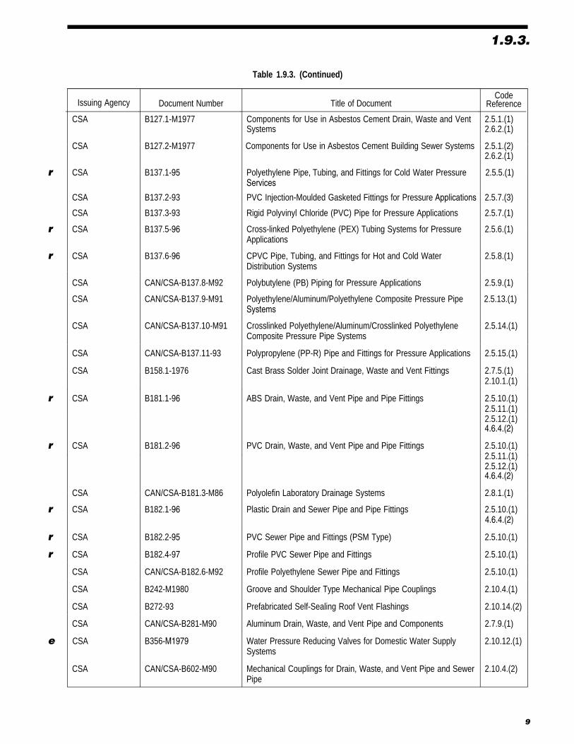
1.9.3.
Table 1.9.3. (Continued)
Issuing Agency Document Number Title of DocumentCode
Reference
CSA B127.1-M1977 Components for Use in Asbestos Cement Drain, Waste and VentSystems
2.5.1.(1)2.6.2.(1)
CSA B127.2-M1977 Components for Use in Asbestos Cement Building Sewer Systems 2.5.1.(2)2.6.2.(1)
r CSA B137.1-95 Polyethylene Pipe, Tubing, and Fittings for Cold Water PressureServices
2.5.5.(1)
CSA B137.2-93 PVC Injection-Moulded Gasketed Fittings for Pressure Applications 2.5.7.(3)
CSA B137.3-93 Rigid Polyvinyl Chloride (PVC) Pipe for Pressure Applications 2.5.7.(1)
r CSA B137.5-96 Cross-linked Polyethylene (PEX) Tubing Systems for PressureApplications
2.5.6.(1)
r CSA B137.6-96 CPVC Pipe, Tubing, and Fittings for Hot and Cold WaterDistribution Systems
2.5.8.(1)
CSA CAN/CSA-B137.8-M92 Polybutylene (PB) Piping for Pressure Applications 2.5.9.(1)
CSA CAN/CSA-B137.9-M91 Polyethylene/Aluminum/Polyethylene Composite Pressure PipeSystems
2.5.13.(1)
CSA CAN/CSA-B137.10-M91 Crosslinked Polyethylene/Aluminum/Crosslinked PolyethyleneComposite Pressure Pipe Systems
2.5.14.(1)
CSA CAN/CSA-B137.11-93 Polypropylene (PP-R) Pipe and Fittings for Pressure Applications 2.5.15.(1)
CSA B158.1-1976 Cast Brass Solder Joint Drainage, Waste and Vent Fittings 2.7.5.(1)2.10.1.(1)
r CSA B181.1-96 ABS Drain, Waste, and Vent Pipe and Pipe Fittings
4.6.4.(2)
2.5.10.(1)2.5.11.(1)2.5.12.(1)
r CSA B181.2-96 PVC Drain, Waste, and Vent Pipe and Pipe Fittings
4.6.4.(2)
2.5.10.(1)2.5.11.(1)2.5.12.(1)
CSA CAN/CSA-B181.3-M86 Polyolefin Laboratory Drainage Systems 2.8.1.(1)
r CSA B182.1-96 Plastic Drain and Sewer Pipe and Pipe Fittings4.6.4.(2)2.5.10.(1)
r CSA B182.2-95 PVC Sewer Pipe and Fittings (PSM Type) 2.5.10.(1)
r CSA B182.4-97 Profile PVC Sewer Pipe and Fittings 2.5.10.(1)
CSA CAN/CSA-B182.6-M92 Profile Polyethylene Sewer Pipe and Fittings 2.5.10.(1)
CSA B242-M1980 Groove and Shoulder Type Mechanical Pipe Couplings 2.10.4.(1)
CSA B272-93 Prefabricated Self-Sealing Roof Vent Flashings 2.10.14.(2)
CSA CAN/CSA-B281-M90 Aluminum Drain, Waste, and Vent Pipe and Components 2.7.9.(1)
e CSA B356-M1979 Water Pressure Reducing Valves for Domestic Water SupplySystems
2.10.12.(1)
CSA CAN/CSA-B602-M90 Mechanical Couplings for Drain, Waste, and Vent Pipe and SewerPipe
2.10.4.(2)
9

1.9.3.
Table 1.9.3. (Continued)
Issuing Agency Document Number Title of Document CodeReference
CSA CAN/CSA-F379.1-88 Solar Domestic Hot Water Systems (Liquid to Liquid Heat Transfer) 2.10.13.(1)
CSA CAN/CSA-F383-87 Installation Code for Solar Domestic Hot Water Systems 6.1.8.(1)
CSA G401-93 Corrugated Steel Pipe Products 2.6.8.(1)
r NFPA 13-1996 Installation of Sprinkler Systems 6.2.4.(1)
e ULC CAN4-S114-M80 1.3.2.(1)Test for Determination of Non-Combustibilityin Building Materials
10

Section 2Materials and Equipment
2.1. General2.1.1. Defects in Products and Materials
1) All materials, systems and equipment in-stalled to meet the requirements of this Code shallbe free from defects and possess the necessary char-acteristics to perform their intended functions wheninstalled.
2.1.2. Exposure of Materials
1) Where unusual conditions exist such asexcessively corrosive soil or water, only materialssuited for use in such locations shall be used.
2) Materials and equipment used in adrainage system where excessively corrosive wastesare present shall be suitable for the purpose.
2.1.3. Restrictions on Re-Use
1) Used materials and equipment, includingfixtures, shall not be reused unless they meet the re-quirements of this Code for new materials andequipment and are otherwise satisfactory for theirintended use.
2) Materials and equipment that have beenused for a purpose other than the distribution ofpotable water shall not be subsequently used in apotable water system.
2.1.4. Identification
1) Every length of pipe and every fittingshall
a) have cast, stamped or indelibly markedon it the maker’s name or mark and theweight or class or quality of the product,or
b) be marked in accordance with the rele-vant standard.
2) Markings required in Sentence (1) shallbe visible after installation.
2.1.5. Pipe or Piping
1) Where the term pipe or piping is used, itshall also apply to tube or tubing unless otherwisestated.
2.1.6. Withstanding Pressure
1) Piping, fittings and joints used in pres-sure sewer, forcemain or sump pump dischargeapplications shall be capable of withstanding atleast one and one-half times the maximum potentialpressure.
2.2. Fixtures2.2.1. Surface Requirements
1) Every fixture shall have a smooth, hard,corrosion-resistant surface free from flaws andblemishes that may interfere with cleaning.
2.2.2. Conformance to Standards
1) Every fixture shall conform to CSA B45.0,“General Requirements for Plumbing Fixtures,” asapplicable.
2) Every vitreous china fixture shall conformto CSA B45.1, “Ceramic Plumbing Fixtures.”
3) Every enamelled cast iron fixture shallconform to CSA B45.2, “Enamelled Cast IronPlumbing Fixtures.”
4) Every porcelain enamelled steel fixtureshall conform to CSA B45.3, “Porcelain-EnamelledSteel Plumbing Fixtures.”
5) Every stainless steel fixture shall conformto CSA B45.4, “Stainless Steel Plumbing Fixtures.”
6) Every plastic fixture shall conform toCSA B45.5, “Plastic Plumbing Fixtures.”
7) Every hydromassage bathtub shall con-form to CAN/CSA-B45S1, “Supplement No. 1, eHydromassage Bathtubs, to CAN/CSA-B45 Series-88,CSA Standards on Plumbing Fixtures.”
2.2.3. Showers
1) Every shower receptor shall be con-structed and arranged so that water cannot leakthrough the walls or floor.
2) Not more than 6 shower heads shall beserved by a single shower drain.
11

2.2.3.
3) Where 2 or more shower heads areserved by a shower drain, the floor shall be slopedand the drain located so that water from one headcannot flow over the area that serves another head.(See Appendix A.)
4) Except for column showers, when a bat-tery of shower heads is installed, the horizontaldistance between 2 adjacent shower heads shall benot less than 750 mm.
2.2.4. Concealed Overflows
1) A dishwashing sink and a food prepara-tion sink shall not have concealed overflows. (SeeAppendix A.)
2.2.5. Water Closets in PublicWashrooms
1) When a water closet is installed in awashroom for public use it shall be of the elongatedtype and provided with a seat of the open fronttype.
2.3. Traps andInterceptors
2.3.1. Traps
1) Except as provided for in Sentence (2),every trap shall:
a) have a trap seal depth of not less than38 mm,
b) be so designed that failure of the sealwalls will cause exterior leakage, and
c) have a water seal that does not dependon the action of moving parts.
(See Appendix A.)
2) The trap seal depth on fixtures draining toan acid waste system shall be a minimum of 50 mm.
3) Every trap that serves a lavatory, a sinkor a laundry tray shall
a) be provided with a cleanout plug locatedat the lowest point of the trap and of thesame material as the trap, except that acast-iron trap shall be provided with abrass cleanout plug, or
b) be designed so that part of the trap canbe completely removed by screwed con-nections for cleaning purposes.
(See Appendix A.)
4) A bell trap shall not be installed in adrainage system. (See Appendix A.)
5) A drum trap shall not be used as a fixturetrap unless required to serve as an interceptor andaccess for servicing is provided.
2.3.2. Interceptors
1) Every interceptor shall be designed so thatit can be readily cleaned.
2) Every grease interceptora) shall be designed so that it does not be-
come air bound andb) shall not have a water jacket.
2.3.3. Tubular Traps
1) Tubular metal or plastic traps conformingto CSA B125, “Plumbing Fittings,” shall be usedonly in accessible locations.
2.4. Pipe Fittings
2.4.1. T and Cross Fittings(See Appendix A.)
1) A T fitting shall not be used in a drainagesystem except to connect a vent pipe.
2) A cross fitting shall not be used in adrainage system.
2.4.2. Sanitary T Fittings(See Appendix A.)
1) A single or double sanitary T fitting shallnot be used in a nominally horizontal soil-or-wastepipe, except that a single sanitary T fitting may beused to connect a vent pipe.
2) A double sanitary T fitting shall not beused to connect the trap arms of
a) back outlet water closets installed back-to-back, or
b) 2 urinals where no cleanout fitting is pro-vided above the connection.
2.4.3. One-Quarter Bends
1) A one-quarter bend of 4 in. size or lessthat has a centre-line radius that is less than the sizeof the pipe shall not be used to join 2 soil-or-wastepipes.
2.4.4. Sisson Fittings
1) A sisson fitting shall not be installed in anominally horizontal soil-or-waste pipe.
12

2.5.7.
2.5. Non-Metallic Pipeand Fittings(For a summary of pipe applications seeAppendix A.)
2.5.1. Asbestos-Cement Drainage Pipeand Fittings
1) Except as provided in Sentence (2),asbestos-cement pipe and its fittings for use in adrain, waste or vent system shall conform to
r a) CAN/CGSB-34.22, “Asbestos-CementDrain Pipe,” or
b) CSA B127.1-M, “Components for Use inAsbestos Cement Drain, Waste and VentSystems.”
2) Asbestos-cement pipe and fittings usedunderground either outside a building or under abuilding shall conform to Sentence (1) or to
r a) CAN/CGSB-34.9, “Asbestos-CementSewer Pipe,”
r b) CAN/CGSB-34.23, “Asbestos-CementHouse Connection Sewer Pipe,” or
c) CSA B127.2-M, “Components for Use inAsbestos Cement Building SewerSystems.”
2.5.2. Asbestos-Cement Water Pipe andFittings
1) Asbestos-cement water pipe, couplingsand bends shall conform to CAN/CGSB-34.1,
r “Asbestos-Cement Pressure Pipe.”
2) Asbestos-cement water pipe shall not beused above ground.
2.5.3. Concrete Pipe and Fittings
1) Concrete pipe shall conform toa) CAN/CSA-A257.1-M, “Circular Concrete
Culvert, Storm Drain, Sewer Pipe, andFittings,” or
b) CAN/CSA-A257.2-M, “Reinforced Circu-lar Concrete Culvert, Storm Drain, SewerPipe, and Fittings.” of CSA Series A257,“Standards for Concrete Pipe.”
2) Joints with internal elastomeric gasketsshall conform to CAN/CSA-A257.3-M, “Joints forCircular Concrete Sewer and Culvert Pipe, ManholeSections, and Fittings Using Rubber Gaskets.” of CSASeries A257, “Standards for Concrete Pipe.”
3) Concrete fittings fabricated on the sitefrom lengths of pipe shall not be used. (SeeAppendix A.)
4) Concrete pipe shall not be used aboveground inside a building.
5) Precast reinforced circular concrete man-hole sections, catch basins and fittings shall conform
to CAN/CSA-A257.4-M, “Precast Reinforced CircularConcrete Manhole Sections, Catch Basins, and Fittings.” eof CSA Series A257, “Standards for Concrete Pipe.”
2.5.4. Vitrified Clay Pipe and Fittings
1) Vitrified clay pipe and fittings shall con-form to CSA A60.1-M, “Vitrified Clay Pipe.”
2) Couplings and joints for vitrified claypipe shall conform to CSA A60.3-M, “Vitrified ClayPipe Joints.”
3) Vitrified clay pipe and fittings shall notbe used except for an underground part of adrainage system.
2.5.5. Polyethylene Pipe and Fittings
1) Polyethylene water pipe, tubing andfittings shall conform to Series 160 of CSA B137.1, r“Polyethylene Pipe, Tubing, and Fittings forCold Water Pressure Services.”
2) Polyethylene water pipe shall not beused except for a water service pipe.
3) Butt fusion fittings for polyethylene pipeshall conform to ASTM D 3261, “Butt Heat FusionPolyethylene (PE) Plastic Fittings for Polyethylene(PE) Plastic Pipe and Tubing.”
2.5.6. Crosslinked Polyethylene Pipe andFittings
1) Crosslinked polyethylene pipe and its as-sociated fittings used in hot and cold potable watersystems shall conform to CSA B137.5, “Cross-linked rPolyethylene (PEX) Tubing Systems for PressureApplications.” (See Appendix A.)
2.5.7. PVC Pipe and Fittings
1) PVC water pipe, fittings and solvent ce-ment shall
a) conform to CSA B137.3, “Rigid PolyvinylChloride (PVC) Pipe for Pressure Appli-cations,” and
b) have a pressure rating of not less than1 100 kPa.
2) PVC water pipe fittings shall conform toa) ASTM D 2466, “Poly(Vinyl Chloride) r
(PVC) Plastic Pipe Fittings, Schedule 40,”or
b) ASTM D 2467, “Poly(Vinyl Chloride) r(PVC) Plastic Pipe Fittings,Schedule 80.”
3) PVC injection moulded gasketed fittingsshall conform to CSA B137.2, “PVC Injection-Moulded Gasketed Fittings for Pressure Applica-tions.”
13

2.5.7.4) PVC water pipe and fittings referred to
in Sentences (1), (2) and (3) shall not be used in ahot water system.
2.5.8. CPVC Pipe, Fittings and SolventCements
1) CPVC hot and cold water pipe, fittingsand solvent cements shall conform to CSA B137.6,
r “CPVC Pipe, Tubing, and Fittings for Hot andCold Water Distribution Systems.”
2) The design temperature and design pres-g) ASTM F 628, “Acrylonitrile-Butadiene- rsure of a CPVC piping system shall conform to
Styrene (ABS) Schedule 40 Plastic Drain,Table 2.5.8.Waste, and Vent Pipe With a Cellular Core.”
Table 2.5.8.Maximu m Permitte d Pressur e for CPVC Pipin g at Various
TemperaturesForming Part of Sentence 2.5.8.(2)
Maximum Temperature ofWater, �C
Maximum PermittedPressures, kPa
10 3 15020 2 90030 2 50040 2 10050 1 70060 1 30070 1 00080 70090 500
100 400
2.5.9. Polybutylene Pipe and Fittings
1) Polybutylene pipe and its associated fit- c) ASTM F 628, “Acrylonitrile-Butadiene- rtings shall conform to CAN/CSA-B137.8-M, Styrene (ABS) Schedule 40 Plastic Drain,“Polybutylene (PB) Piping for Pressure Waste, and Vent Pipe With a Cellular Core.”Applications.”
2) Joints in polybutylene tubing shall not beembedded in or installed under a concrete gradeslab.
3) Polybutylene pipe and fittings shall notbe used for a continuously circulating hot water lineor the first metre of any branch off of the continu-ously circulating hot water line.
2.5.10. Plastic Pipe, Fittings andSolvent Cement UsedUnderground
1) Plastic pipe, fittings and solvent cementused underground outside a building or under abuilding in a drainage system shall conform to
r a) CSA-B181.1, “ABS Drain, Waste,and Vent Pipe and Pipe Fittings,”
r b) CSA-B181.2, “PVC Drain, Waste,and Vent Pipe and Pipe Fittings,”
c) CSA-B182.1, “Plastic Drain and rSewer Pipe and Pipe Fittings,” with apipe stiffness not less than 320 kPa,
d) CSA-B182.2, “PVC Sewer Pipe rand Fittings (PSM Type),” with a pipestiffness not less than 320 kPa,
e) CSA-B182.4, “Profile PVC Sewer rPipe and Fittings,” with a pipe stiffnessnot less than 320 kPa, or
f) CAN/CSA-B182.6-M, “ProfilePolyethylene Sewer Pipe and Fittings,” witha pipe stiffness of not less than 320 kPa.
(See Appendix A.)
2.5.11. Transition Solvent Cement(See Appendix A.)
1) Solvent cement for transition joints shallconform to
a) CSA-B181.1, “ABS Drain, Waste, rand Vent Pipe and Pipe Fittings,” or
b) CSA-B181.2, “PVC Drain, Waste, rand Vent Pipe and Pipe Fittings.”
2) Transition solvent cement shall only beused for joining an ABS drainage system to a PVCdrainage system.
2.5.12. Plastic Pipe, Fittings and SolventCement Used Above Ground
1) Plastic pipe, fittings and solvent cementused inside or under a building in a drainage or vent-ing system shall conform to
a) CSA-B181.1, “ABS Drain, Waste, rand Vent Pipe and Pipe Fittings,” or
b) CSA-B181.2, “PVC Drain, Waste, rand Vent Pipe and Pipe Fittings.”
(See Appendix A.)2) Requirements for combustible piping
in relation to fire safety shall conform toSentence 3.1.5.15.(1) and Article 3.1.9.4. of Part 3 andSentences 9.10.9.6.(2) to (8) and Article 9.10.9.7. ofPart 9 of the National Building Code of Canada 1995.
3) Where noncombustible piping pierces a fireseparation or a fire stop, the requirements of fire stop-ping of Subsection 3.1.11. of Part 3 and Sentence9.10.9.6.(1) and Article 9.10.15.4. of Part 9 of theNational Building Code of Canada 1995 shall apply.
2.5.13. Polyethylene/Aluminum/Polyethylene Composite Pipe andFittings
1) PE/AL/PE composite pipe and fittingsshall conform to CAN/CSA-B137.9-M,”Polyethylene/Aluminum/Polyethylene CompositePressure Pipe Systems.” (See Appendix A.)
14

2.6.7.
2) PE/AL/PE pipe and fittings shall not beused in hot water systems.
2.5.14. Crosslinked Polyethylene/Aluminum/CrosslinkedPolyethylene Composite PressurePipe and Fittings
1) PEX/AL/PEX composite pipe and fit-tings used in hot and cold potable water systems shallconform to CAN/CSA-B137.10-M, “CrosslinkedPolyethylene/Aluminum/Crosslinked PolyethyleneComposite Pressure Pipe Systems.” (SeeAppendix A.)
2.5.15. Polypropylene Pipe and Fittings
1) Polypropylene pipe and fittings used forhot and cold potable water systems shall conform to
e CAN/CSA-B137.11, ”Polypropylene (PP-R) Pipe andFittings for Pressure Applications.” (See Appendix A.)
2.6. Ferrous Pipe andFittings(For a summary of pipe applications seeAppendix A.)
2.6.1. Cast Iron Drainage and Vent Pipeand Fittings
1) Drainage piping, vent piping and fittingsr made of cast iron shall conform to CSA-B70,
“Cast Iron Soil Pipe, Fittings, and Means ofJoining.”
2) Cast iron soil pipe and fittings shall notbe used in a water system.
2.6.2. Cast Iron Fittings forAsbestos-Cement Drainage Pipe
1) Cast iron fittings designed for use withasbestos-cement pipe for drainage purposes shallconform to the applicable requirements of
a) CSA B127.1-M, “Components for Use inAsbestos Cement Drain, Waste and VentSystems,” or
b) CSA B127.2-M, “Components for Use inAsbestos Cement Building SewerSystems.”
2.6.3. Threaded Cast Iron DrainageFittings
1) Threaded cast iron drainage fittings shallconform to ANSI/ASME B16.12, “Cast-IronThreaded Drainage Fittings.”
2) Threaded cast iron drainage fittings shallnot be used in a water system.
2.6.4. Cast Iron Water Pipes
1) Cast iron water pipes shall conform toANSI/AWWA C151/A21.51, “Ductile-Iron Pipe,Centrifugally Cast, for Water.” r
2) Cement mortar lining for cast iron waterpipes shall conform to ANSI/AWWA C104/A21.4,“Cement-Mortar Lining for Ductile-Iron Pipe eand Fittings for Water.”
3) Cast iron fittings for cast iron or ductile-iron water pipes shall conform to ANSI/AWWAC110/A21.10, “Ductile-Iron and Gray-Iron Fittings,3-in. Through 48-in., for Water and Other Liquids.”
4) Rubber gasket joints for cast-iron andductile-iron pressure pipe for water shall conformto ANSI/AWWA C111/A21.11, “Rubber-GasketJoints for Ductile-Iron Pressure Pipe and Fittings.”
2.6.5. Screwed Cast Iron Water Fittings
1) Screwed cast iron water fittings shall con-form to ANSI/ASME B16.4, “Cast-Iron ThreadedFittings, Classes 125 and 250.”
2) Screwed cast iron water fittings used in awater system shall be cement-mortar lined or galva-nized.
3) Screwed cast iron water fittings shall notbe used in a drainage system.
2.6.6. Screwed Malleable Iron WaterFittings
1) Screwed malleable iron water fittingsshall conform to ANSI/ASME B16.3, “Malleable-Iron Threaded Fittings, Classes 150 and 300.”
2) Screwed malleable iron water fittingsused in a water system shall be cement-mortar linedor galvanized.
3) Screwed malleable iron water fittingsshall not be used in a drainage system.
2.6.7. Steel Pipe
1) Except as provided in Sentences (2) and(3), welded and seamless steel pipe shall not beused in a plumbing system.
2) Galvanized steel pipe is permitted to beused in a drainage system or a venting system aboveground inside a building.
3) Galvanized steel pipe and fittings shallnot be used in a water distribution system except
a) in buildings of industrial occupancy as de-scribed in the National Building Code ofCanada 1995, or
b) for the repair of existing galvanized steelpiping systems.
(See Appendix A.)
15

2.6.7.
4) Galvanized steel pipe and fittings shallconform to ASTM A 53, “Pipe, Steel, Black and Hot-Dipped, Zinc-Coated, Welded and Seamless.”
2.6.8. Corrugated Steel Pipe andCouplings
1) Corrugated steel pipe and couplings shallconform to CSA G401, “Corrugated Steel PipeProducts.”
2) Corrugated steel pipe shall only be usedunderground outside a building in a storm drainagesystem.
3) Couplings for corrugated steel pipe shallbe constructed so that when installed they shall
a) maintain the pipe alignment,b) resist the separation of adjoining lengths
of pipe,c) prevent root penetration, andd) prevent the infiltration of surrounding
material.
2.6.9. Sheet Metal Leaders
1) A sheet metal leader shall not be used ex-cept above ground outside a building.
2.7. Non-Ferrous Pipeand Fittings(For a summary of pipe applications seeAppendix A.)
2.7.1. Copper and Brass Pipe
1) Copper pipe shall conform to ASTM B 42,“Seamless Copper Pipe, Standard Sizes.”
2) Brass pipe shall conform to ASTM B 43,“Seamless Red Brass Pipe, Standard Sizes.”
2.7.2. Brass or Bronze Pipe Flanges andFlanged Fittings
1) Brass or bronze pipe flanges and flangedfittings shall conform to ANSI/ASME B16.24, “CastCopper Alloy Pipe Flanges and Flanged Fittings.”
2.7.3. Brass or Bronze Threaded WaterFittings
1) Brass or bronze threaded water fittingsshall conform to ANSI/ASME B16.15, “Cast BronzeThreaded Fittings, Classes 125 and 250.”
2) Brass or bronze threaded water fittingsshall not be used in a drainage system.
2.7.4. Copper Tube
1) Copper tube shall conform toa) ASTM B 88, “Seamless Copper Water
Tube,” orb) ASTM B 306, “Copper Drainage Tube
(DWV).”
2) Except as provided in Sentence (3), theuse of copper tube shall conform to Table 2.7.4.
3) Copper tube shall not be used for thefixture drain or the portion of the vent below theflood level rim of a flush valve-operated urinal.
Table 2.7.4.Permitted Use of Copper Tube and Pipe
Forming Part of Article 2.7.4.
Plumbing Purposes
Water Distribution System Drainage System Venting SystemType of CopperTube or Pipe
WaterService
PipeUnder-ground
Aboveground
BuildingSewer Under-
groundAboveground
Under-ground
Aboveground
K & L hard N N P P P P P PK & L soft P P P N N N N N
M hard N N P N N P N PM soft N N N N N N N NDWV N N N N N P N P
P-Permitted N-Not Permitted
16

2.10.2.
2.7.5. Solder-Joint Drainage Fittings
1) Solder-joint fittings for drainage systemsshall conform to
a) CSA B158.1, “Cast Brass Solder JointDrainage, Waste and Vent Fittings,” or
b) ANSI/ASME B16.29, “Wrought Copperand Wrought Copper Alloy Solder-JointDrainage Fittings – DWV.”
2) Solder-joint fittings for drainage systemsshall not be used in a water system.
2.7.6. Solder-Joint Water Fittings
1) Except as provided in Sentence (2),solder-joint fittings for water systems shall conform to
a) ANSI B16.18, “Cast Copper Alloy Solder-Joint Pressure Fittings,” or
b) ANSI/ASME B16.22, “Wrought Copperand Copper Alloy Solder-Joint PressureFittings.”
2) Solder-joint fittings for water systems notmade by casting or the wrought process shall con-form to the applicable requirements of ANSI B16.18,“Cast Copper Alloy Solder-Joint Pressure Fittings.”
2.7.7. Flared-Joint Fittings for CopperWater Systems
1) Flared-joint fittings for copper tube watersystems shall conform to ANSI/ASME B16.26, “CastCopper Alloy Fittings for Flared Copper Tubes.”
2) Flared-joint fittings for copper tube watersystems not made by casting shall conform to the ap-plicable requirements of ANSI/ASME B16.26, “CastCopper Alloy Fittings for Flared Copper Tubes.”
2.7.8. Lead Waste Pipe and Fittings
1) Lead waste pipe and fittings shall conformto CSA B67, “Lead Service Pipe, Waste Pipe, Traps,Bends and Accessories.”
2) When there is a change in size of a leadcloset bend, the change shall be in the verticalsection of the bend or made in such a manner thatthere shall be no retention of liquid in the bend.
3) Lead waste pipe and fittings shall not beused in a water system or for a building sewer.
2.7.9. Aluminum DWV Pipe andComponents
1) Aluminum DWV pipe and componentsshall conform to CAN/CSA-B281-M, “AluminumDrain, Waste, and Vent Pipe and Components.”
2) Except as provided in Sentence (3), alu-minum DWV pipe shall only be used above groundin a drainage system or a venting system.
3) Aluminum DWV pipe shall not be useddownstream of a fixture or device which dischargesacid or alkali containing waste above 60�C. (SeeAppendix A.)
2.8. Corrosion ResistantMaterials
2.8.1. Pipes and Fittings
1) Pipes and fittings to be used for drainageand venting of acid and corrosive wastes shall con-form to:
a) ASTM A 518, “Corrosion-Resistant eHigh-Silicon Iron Castings,”
b) ASTM C 1053, “Borosilicate Glass Pipe eand Fittings for Drain, Waste, andVent (DWV) Applications,” or
c) CAN/CSA-B181.3-M, “PolyolefinLaboratory Drainage Systems.”
2.9. Jointing Materials2.9.1. Cement Mortar
1) Cement mortar shall not be used forjointing.
2.9.2. Wiping Solder and Caulking Lead
1) Wiping solder and caulking lead shallconform to CSA B67, “Lead Service Pipe, WastePipe, Traps, Bends and Accessories.”
2) Solders for solder joint fittings shall con-form to ASTM B 32, “Solder Metal,” in accordancewith the recommended use.
3) Solders and fluxes having a lead contentin excess of 0.2% shall not be used in a potable watersystem.
2.10. MiscellaneousMaterials
2.10.1. Brass Floor Flanges
1) Brass floor flanges shall conform to CSAB158.1, “Cast Brass Solder Joint Drainage, Wasteand Vent Fittings.”
2.10.2. Brass Screws, Bolts, Nuts andWashers
1) Every screw, bolt, nut and washer shallbe of brass when used
17

2.10.2.
a) to connect a water closet to a water closetflange,
b) to anchor the water closet flange to thefloor, or
c) to anchor the water closet to the floor.
2.10.3. Cleanout Fittings
1) Every plug, cap, nut or bolt that is in-tended to be removable from a ferrous fitting shallbe of a non-ferrous material.
2) A cleanout fitting that as a result of nor-mal maintenance operations cannot withstand thephysical stresses of removal and reinstallation orcannot ensure a gas-tight seal shall not be installed.
2.10.4. Mechanical Couplings
1) Groove and shoulder type mechanicalcouplings for pressure applications shall conform toCSA B242-M, “Groove and Shoulder TypeMechanical Pipe Couplings.”
2) Mechanical couplings for non-pressureapplications shall conform to CAN/CSA-B602-M,“Mechanical Couplings for Drain, Waste, and VentPipe and Sewer Pipe.”
2.10.5. Saddle Hubs
1) A saddle hub or fitting shall not be in-stalled in drainage, venting or water systems. (SeeAppendix A.)
2.10.6. Supply and Waste Fittings
1) Supply and waste fittings shall conformto CSA B125, “Plumbing Fittings.”
2.10.7. Shower Valves
1) Except as provided for in Sentence (2), allshower valves shall be pressure-balanced orthermostatic-mixing valves conforming to CSAB125, “Plumbing Fittings.”
2) Pressure-balanced or thermostatic-mixingvalves shall not be required for showers if the hotwater supply for such showers is controlled by amaster thermostatic-mixing valve conforming toCSA B125, “Plumbing Fittings.”
3) Pressure-balanced and thermostatic-mixing valves shall be
a) designed such that the outlet temperaturedoes not exceed 49�C, or
b) equipped with high-limit stops whichshall be adjusted to a maximum hot wa-ter setting of 49�C.
2.10.8. Direct Flush Valves
1) Every direct flush valve shall
a) open fully and close positively under ser-vice pressure,
b) complete its cycle of operation automati-cally,
c) be provided with a means of regulatingthe volume of water that it discharges,and
d) be provided with a vacuum breaker unlessthe fixture is designed so that back-siphonage cannot occur.
2.10.9. Drinking Fountain Bubblers
1) The orifice of every drinking fountainbubbler shall
a) be of the shielded type, andb) direct the water upward at an angle of
approximately 45�.
2) Every drinking fountain bubbler shall in-clude a means of regulating the flow to the orifice.
3) Bubblers shall be installed only on drink-ing fountains. (See Appendix A.)
2.10.10. Back-Siphonage Preventers andBackflow Preventers
1) Except as provided in Sentence (2), back-siphonage preventers and backflow preventers shallconform to
a) CAN/CSA-B64.0, “Definitions, GeneralRequirements, and Test Methods for Vac-uum Breakers and Backflow Preventers,”
b) CAN/CSA-B64.1.1, “Vacuum Breakers,Atmospheric Type (AVB),”
c) CAN/CSA-B64.1.2, “Vacuum Breakers,Pressure Type (PVB),”
d) CAN/CSA-B64.2, “Vacuum Breakers,Hose Connection Type (HCVB),”
e) CAN/CSA-B64.2.1, “Vacuum Breakers,Hose Connection Type (HCVB) withManual Draining Feature,”
f) CAN/CSA-B64.2.2, “Vacuum Breakers,Hose Connection Type (HCVB) withAutomatic Draining Feature,”
g) CAN/CSA-B64.3, “Backflow Preventers,Dual Check Valve Type withAtmospheric Port (DCAP),”
h) CAN/CSA-B64.4, “Backflow Preventers,Reduced Pressure Principle Type(RP),”
i) CAN/CSA-B64.5, “Backflow Preventers,Double-Check-Valve Type (DCVA),”
j) CAN/CSA-B64.6, “Backflow Preventers,Dual Check Valve Type (DuC),”
k) CAN/CSA-B64.7, “Vacuum Breakers,Laboratory Faucet Type (LFVB),” or
l) CAN/CSA-B64.8, “Backflow Preventers,Dual Check Valve Type withIntermediate Vent (DuCV),”
18

2.10.14.
2) Back-siphonage preventers for tank typewater closets (anti-siphon ballcocks) shall conformto CSA B125, “Plumbing Fittings.”
2.10.11. Relief Valves
1) Temperature relief, pressure relief, com-bined temperature and pressure relief and vacuumrelief valves shall conform to CAN1-4.4-M, “Tem-perature, Pressure, Temperature and Pressure ReliefValves and Vacuum Relief Valves.”
2.10.12. Reducing Valves
1) Direct acting water pressure reducingvalves for domestic water supply systems shall con-
e form to CSA B356-M, “Water Pressure ReducingValves for Domestic Water Supply Systems.”
2.10.13. Solar Domestic Hot Water
1) Equipment for solar heating of potablewater shall conform to CAN/CSA-F379.1, ”SolarDomestic Hot Water Systems (Liquid to LiquidHeat Transfer).”
2.10.14. Vent Pipe Flashing
1) Flashing fabricated on-site for vent pipesshall be fabricated from
a) copper sheet not less than 0.33 mm thick,b) aluminium sheet not less than 0.61 mm
thick,c) alloyed zinc sheet not less than 0.35 mm
thick,d) lead sheet not less than 2.16 mm thick,e) galvanized steel sheet not less than
0.41 mm thick, orf) polychloroprene (neoprene) not less than
2.89 mm thick.
2) Prefabricated flashing for vent pipes shallconform to CSA B272, “Prefabricated Self-SealingRoof Vent Flashings.” (See Article 5.6.5. for locationof vent pipe terminals.)
19

20

4.6.4.
4.5.2. Traps for Storm Drainage Systems
1) Where a storm drainage system is con-nected to a combined building sewer or a publiccombined sewer, a trap shall be installed between anyopening in the system and the drain or sewer, ex-cept that no trap is required if the opening is theupper end of a leader that terminates
a) at a roof that is used only for weatherprotection,
b) not less than 900 mm above or not lessthan 3.5 m in any other direction fromany air inlet, openable window or door,and
c) not less than 1.8 m from a property line.(See Appendix A.)
2) A floor drain which drains to a stormdrainage system shall be protected by a trap which
a) is located between the floor drain and aleader, storm building drain or stormbuilding sewer,
b) may serve all floor drains located in thesame room, and
c) need not be protected by a vent pipe.
4.5.3. Connection of Subsoil DrainagePipe to a Sanitary DrainageSystem
1) Where a subsoil drainage pipe is connectedto a sanitary drainage system, the connection shall bemade on the upstream side of a trap with a cleanoutor a trapped sump. (See Appendix A.)
4.5.4. Location and Cleanout forBuilding Traps
1) Where a building trap is installed it shalla) be provided with a cleanout fitting on the
upstream side of and directly over thetrap,
b) be located upstream of the buildingcleanout,
c) be locatedi) inside the building as close as practi-
cal to the place where the buildingdrain leaves the building, or
ii) outside the building in a manhole.(See Appendix A.)
4.5.5. Trap Seals
1) Provision shall be made for maintainingthe trap seal of a floor drain by
a) the use of a trap seal primer,b) using the drain as a receptacle for an in-
free circulation of air shall not be installed in a
directly connected drinking fountain, or
Fittings, and Means of Joining”; CSA B181.1, “ABS
c) other equally effective means. (See building drain provided that it is a “normally open”Appendix A.) design conforming to CSA B70, “Cast Iron Soil Pipe,
4.6. Arrangement ofDrainage Piping
4.6.1. Separate Systems1) No vertical soil-or-waste pipe shall conduct
both sewage and storm water.
2) A combined building drain shall not be in-stalled. (See Appendix A.)
3) There shall be no unused open ends in adrainage system and dead ends shall be so graded thatwater will not collect in them.
4.6.2. Location of Soil-or-Waste Pipes
1) A soil-or-waste pipe shall not be located di-rectly above
a) non-pressure potable water storage tanks,b) manholes in pressure potable water stor-
age tanks, orc) food-handling or processing equipment.
4.6.3. Sumps or Tanks(See Appendix A.)
1) Piping that is too low to drain into abuilding sewer by gravity shall be drained to a sumpor receiving tank.
2) Where the sump or tank receives sewageit shall be water- and air-tight and shall be vented.
3) Equipment such as a pump or ejectorthat can lift the contents of the sump or tank anddischarge it into the building drain or building sewershall be installed.
4) Where the equipment does not operateautomatically the capacity of the sump shall be suf-ficient to hold at least a 24 h accumulation of liquid.
5) Where there is a building trap the dis-charge pipe from the equipment shall be connectedto the building drain downstream of the trap.
6) The discharge pipe from every sewagesump shall be equipped with a union, a check valveand a shut-off valve installed in that sequence in thedirection of discharge.
7) The discharge piping from a pump orejector shall be sized for optimum flow velocities atpump design conditions.
4.6.4. Protection from Backflow
1) Except as permitted in Sentence (2), a rbackwater valve or a gate valve that would prevent
building drain or in a building sewer. (See Appendix A.)
2) A backwater valve may be installed in a r
29

4.6.4.
subject to backflow, a gate valve or a backwater valveshall be installed on every fixture drain connected tothem when the fixture is located below the level ofthe adjoining street.
r 4) Where the fixture is a floor drain, aremovable screw cap may be installed on the up-stream side of the trap.
r 5) Where more than one fixture is located ona storey and all are connected to the same branch,the gate valve or backwater valve may be installed onthe branch.
r 6) A subsoil drainage pipe that drains into asanitary drainage system that is subject to surchargeshall be connected in such a manner that sewagecannot back up into the subsoil drainage pipe. (SeeAppendix A.)
4.6.5. Mobile Home Sewer Service1) A building sewer intended to serve a mo-
bile home shall bea) not less than 4 in. in size,b) terminated above ground,c) provided with
i) a tamperproof terminal connectionthat is capable of being repeatedlyconnected, disconnected and sealed,
ii) a protective concrete pad, andiii) a means to protect it from frost
heave, andd) designed and constructed in accordance
with good engineering practice.
4.7. Cleanouts4.7.1. Cleanouts for Drainage Systems
1) Every sanitary drainage system and stormdrainage system shall be provided with cleanouts thatwill permit cleaning of the entire system. (SeeAppendix A.)
2) A cleanout fitting shall be provided on theupstream side and directly over every running trap.
3) Every interior leader shall be provided witha cleanout fitting at the bottom of the leader or notmore than 3 m upstream from the bottom of the leader.
4) Where a cleanout is required on a buildingsewer 8 in. or larger in size, it shall be a manhole.
5) A building sewer shall not change direc-tion or slope between the building and public seweror between cleanouts, except that pipes not morethan 6 in. in size may change direction
a) by not more than 5� every 3 m, or
Drain, Waste, and Vent Pipe and Pipe Fittings”; b) by the use of fittings with a cumulative
6) Every building drain shall be provided
r 3) Except as provided in Sentences (4), (5)
CSA B181.2, “PVC Drain, Waste, and Vent Pipe and change in direction of not more than 45o.Pipe Fittings”; or CSA B182.1, “Plastic Drain andSewer Pipe and Pipe Fittings”; and does not serve with a cleanout fitting that is located as close as
and (6), where a building drain or a branch may be
more than one dwelling unit. practical to the place where the building drain leavesthe building.
7) Every soil-or-waste stack shall be providedwith a cleanout fitting
a) at the bottom of the stack,b) not more than 3 m upstream of the
bottom of the stack, orc) on a Y fitting connecting the stack to the
building drain or branch.
8) A cleanout shall be provided to permit thecleaning of the piping downstream of an interceptor.
9) Cleanouts shall be installed so that the cu-mulative change in direction is not more than 90�
between cleanouts in a drip pipe from a food recep-tacle or in a fixture drain serving a kitchen sink. (SeeAppendix A.)
4.7.2. Size and Spacing of Cleanouts
1) Except as provided in Sentences (2) and(3), the size and spacing of cleanouts in nominally hor-izontal pipes of a drainage system shall conform toTable 4.7.2.
Table 4.7.2.Permitted Size and Spacing for Cleanouts
Forming Part of Sentence 4.7.2.(1)
Maximum Spacing, mSize ofDrainagePipe, in.
Minimum Sizeof Cleanout, in. One Way
RoddingTwo WayRodding
21/2 or less Same size asdrainage pipe
7.5 15
3 and 4 3 15 30over 4 4 26 52
2) The spacing between manholes serving abuilding sewer
a) 24 in. or less in size shall not exceed90 m, and
b) over 24 in. in size shall not exceed 150 m.
3) The developed length of a building sewer be-tween the building and the first manhole to whichthe building sewer connects shall not exceed 75 m.
4) Where a building sewer connects to an-other building sewer other than by a manhole, thedeveloped length between the building and the buildingsewer to which it connects shall not exceed 30 m.
5) Cleanouts capable of rodding in one direc-tion only shall be installed to rod in the direction offlow.
30

6.2.10.
and installed so that non-potable water or substancesthat may render the water non-potable cannot enterthe system.
2) A water treatment device or apparatusshall not be installed unless it can be demonstratedthat the device or apparatus will not introduce sub-stances into the system that may endanger health.
6.2.2. Back-Siphonage
1) Potable water connections to fixtures,tanks, vats or other devices not subject to pressureabove atmospheric and containing other than potablewater shall be installed so as to prevent back-siphonage in conformance with Sentence (2).
2) Except as provided in Sentence 6.2.10.(2),back-siphonage shall be prevented by the installationof
a) an air gap,b) an atmospheric vacuum breaker,c) a pressure vacuum breaker,d) a hose connection vacuum breaker,e) a dual check valve backflow preventer with
atmospheric port,f) a double check valve assembly,g) a reduced pressure principle backflow pre-
venter,h) a dual check valve backflow preventer,i) a laboratory faucet type vacuum breaker, orj) a dual check valve backflow preventer with
vent.
6.2.3. Backflow Caused by BackPressure
1) Potable water connections to fixtures,tanks, vats, boilers or other devices containing otherthan potable water and subject to pressure above at-mospheric shall be arranged to prevent backflowcaused by back pressure in conformance withSentences (2) and (3).
2) Except as provided in Article 6.2.4., back-flow caused by back pressure of non-toxic substancesinto a potable water system shall be prevented by theinstallation of
a) an air gap,b) a dual check valve backflow preventer with
atmospheric port,c) a dual check valve backflow preventer,d) a dual check valve backflow preventer with
vent,e) a double check valve assembly, orf) a reduced pressure principle backflow pre-
venter.
3) Backflow caused by back pressure of toxicsubstances into a potable water system shall be pre-vented by the installation of
a) an air gap, orb) a reduced pressure principle backflow pre-
venter.
6.2.4. Backflow from Fire ProtectionSystems(See Appendix A.)
1) Backflow caused by back-siphonage or backpressure from fire sprinkler systems where watertreatment is not added is permitted to be preventedby an alarm check valve installed in conformancewith NFPA 13, “Installation of Sprinkler rSystems.”
2) Backflow caused by back-siphonage or backpressure from standpipe systems where water treat-ment is not added is permitted to be prevented bythe installation of a detector check valve with aresilient-seated check valve on the metered bypass.
6.2.5. Separation of Water SupplySystems
1) No private water supply system shall be in-terconnected with a public water supply system.
6.2.6. Premise or Zone Isolation
1) In addition to a backflow preventer re-quired by this Subsection for buildings or facilitieswhere potentially severe health hazard may becaused by backflow, a potable water system shall beprovided with premise or zone isolation by the in-stallation of a reduced pressure principle backflowpreventer. (See Appendix A.)
6.2.7. Hose Bibb
1) Where a hose bibb is installed outside abuilding, inside a garage or in an area where there isan identifiable risk of contamination, the potable wa-ter system shall be protected against backflowthrough the hose bibb.
6.2.8. Cleaning of Systems
1) A newly installed part of a potable watersystem shall be cleaned before the system is put intooperation.
6.2.9. Air Gap
1) An air gap shall not be located in a nox-ious environment.
2) Every air gap shall be not less than25 mm high and at least twice the diameter of the
opening of the water supply outlet in height.(See Appendix A.)
6.2.10. Vacuum Breakers
1) Where the critical level is not marked onan atmospheric vacuum breaker or pressure vacuumbreaker, the critical level shall be taken as the lowestpoint on the device.
45

6.2.10.
2) Where an atmospheric vacuum breaker isinstalled, it shall be located on the downstream sideof the fixture control valve or faucet so that it will besubject to water supply pressure
a) only when the valve or faucet is open andb) for periods of use not to exceed 12 h
continous. (See Appendix A.)
3) An atmospheric vacuum breaker shall beinstalled so that the critical level is at least the dis-tance specified by the manufacturer at which thedevice will operate safely but not less than 25 mmabove
a) the flood level rim of a fixture or tank, orb) the highest point open to atmosphere in
an irrigation system.
4) A pressure vacuum breaker shall be in-stalled so that the critical level is not less than300 mm above
a) the flood level rim of a fixture or tank, orb) the highest point open to atmosphere in
an irrigation system.
6.2.11. Tank Type Water Closets
1) Tank type water closets shall be providedwith a back-siphonage preventer in conformance withSentence 2.10.10.(2).
6.2.12. Backflow Preventers
1) No bypass piping or other device capableof reducing the effectiveness of a backflow preventershall be installed in a water supply system.
2) Backflow preventers shall be selected, in-stalled, maintained and field tested in conformance
e with CAN/CSA-B64.10-M, “Backflow Prevention Devices - Selection, Installation, Maintenance, andField Testing.”
6.3. Size and Capacityof Pipes(See Appendix A.)
6.3.1. Design
1) Every water distribution system shall bedesigned to provide peak demand flow when the
flow pressures at the supply openings conform toTable 6.3.
6.3.2. Hydraulic Load
1) Except as provided in Sentence (3), thehydraulic load of a fixture or device that is listed inTable 6.3. shall be the number of fixture units givenin the table.
2) Except as provided in Sentences (1) and(3), the hydraulic load of a fixture that is not listedin Table 6.3. is the number of fixture units listed inTable 6.3.2.
3) Where fixtures are supplied with both hotand cold water, the hydraulic loads for maximumseparate demands shall be 75% of the hydraulic loadof the fixture units given in Tables 6.3. and 6.3.2.when using a detailed engineering design method.
6.3.3. Static Pressure
1) Where the static pressure may exceed550 kPa, a pressure reducing valve conforming toArticle 2.10.12. shall be installed to limit the maxi-mum static pressure to not more than 550 kPa inareas that may be occupied.
6.3.4. Size
1) Every water service pipe shall be sized ac-cording to the peak demand flow but shall not beless than 3/4 in. nominal size. r
2) Except as provided in Sentence (3), thesize of a pipe that supplies a fixture or device shallconform to Table 6.3.
3) A tail piece or connector not more than750 mm long and not less than 0.25 in. inside diam-eter may be used to supply water to a fixture ordevice.
46

A-1.6.4.
e Figur e A-1.6.4.Service Piping
59
X X X X X X
XX
XX
X X X X X
XX
public water main public sewer
(a) Permitted
building sewer
water service pipe
property line
public water main public sewer
(b) Permitted
building sewer
water service pipe
Row housingSemi-detached
public water main public sewer
(c) Permitted
building sewer
water service pipe
Row housingSemi-detached
X X X X X X
XX
XX
X X X X X
XX
public water main public sewer
(d) Not permitted
building sewerwater service pipe
property line
A-1.9.3.
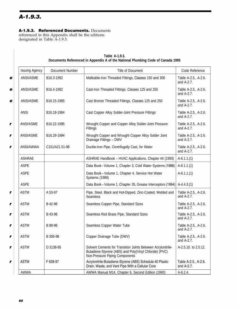
A-1.9.3. Referenced Documents. Documentsreferenced in this Appendix shall be the editionsdesignated in Table A-1.9.3.
Table A-1.9.3.Documents Referenced in Appendix A of the National Plumbing Code of Canada 1995
Issuing Agency Document Number Title of Document Code Reference
e ANSI/ASME B16.3-1992 Malleable-Iron Threaded Fittings, Classes 150 and 300 Table A-2.5., A-2.6.and A-2.7.
e ANSI/ASME B16.4-1992 Cast-Iron Threaded Fittings, Classes 125 and 250 Table A-2.5., A-2.6.and A-2.7.
e ANSI/ASME B16.15-1985 Cast Bronze Threaded Fittings, Classes 125 and 250 Table A-2.5., A-2.6.and A-2.7.
ANSI B16.18-1984 Cast Copper Alloy Solder-Joint Pressure Fittings Table A-2.5., A-2.6.and A-2.7.
r ANSI/ASME B16.22-1995 Wrought Copper and Copper Alloy Solder-Joint PressureFittings
Table A-2.5., A-2.6.and A-2.7.
r ANSI/ASME B16.29-1994 Wrought Copper and Wrought Copper Alloy Solder-JointDrainage Fittings – DWV
Table A-2.5., A-2.6.and A-2.7.
r ANSI/AWWA C151/A21.51-96 Ductile-Iron Pipe, Centrifugally Cast, for Water Table A-2.5., A-2.6.and A-2.7.
ASHRAE ASHRAE Handbook – HVAC Applications, Chapter 44 (1993) A-6.1.1.(1)
ASPE Data Book– Volume 1, Chapter 3, Cold Water Systems (1988) A-6.1.1.(1)
ASPE Data Book – Volume 1, Chapter 4, Service Hot WaterSystems (1989)
A-6.1.1.(1)
ASPE Data Book – Volume 1, Chapter 35, Grease Interceptors (1994) A-4.4.3.(1)
r ASTM A 53-97 Pipe, Steel, Black and Hot-Dipped, Zinc-Coated, Welded andSeamless
Table A-2.5., A-2.6.and A-2.7.
r ASTM B 42-96 Seamless Copper Pipe, Standard Sizes Table A-2.5., A-2.6.and A-2.7.
r ASTM B 43-96 Seamless Red Brass Pipe, Standard Sizes Table A-2.5., A-2.6.and A-2.7.
r ASTM B 88-96 Seamless Copper Water Tube Table A-2.5., A-2.6.and A-2.7.
r ASTM B 306-96 Copper Drainage Tube (DWV) Table A-2.5., A-2.6.and A-2.7.
r ASTM D 3138-95 Solvent Cements for Transition Joints Between Acrylonitrile-Butadiene-Styrene (ABS) and Poly(Vinyl Chloride) (PVC)
r ASTM F 628-97 Acrylonitrile-Butadiene-Styrene (ABS) Schedule 40 Plastic Table A-2.5., A-2.6.
Non-Pressure Piping Components
A-2.5.10. to 2.5.12.
AWWA
Drain, Waste, and Vent Pipe With a Cellular Core and A-2.7.
AWWA Manual M14, Chapter 6, Second Edition (1990) A-6.2.4.
60
A-1.9.3.
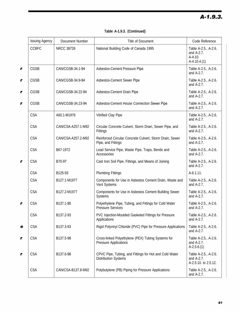
Table A-1.9.3. (Continued)
Issuing Agency Document Number Title of Document Code Reference
CCBFC NRCC 38726 National Building Code of Canada 1995 Table A-2.5., A-2.6.and A-2.7.A-4.10.A-4.10.4.(1)
r CGSB CAN/CGSB-34.1-94 Asbestos-Cement Pressure Pipe Table A-2.5., A-2.6.and A-2.7.
r CGSB CAN/CGSB-34.9-94 Asbestos-Cement Sewer Pipe Table A-2.5., A-2.6.and A-2.7.
r CGSB CAN/CGSB-34.22-94 Asbestos-Cement Drain Pipe Table A-2.5., A-2.6.and A-2.7.
r CGSB CAN/CGSB-34.23-94 Asbestos-Cement House Connection Sewer Pipe Table A-2.5., A-2.6.and A-2.7.
CSA A60.1-M1976 Vitrified Clay Pipe Table A-2.5., A-2.6.and A-2.7.
CSA CAN/CSA-A257.1-M92 Circular Concrete Culvert, Storm Drain, Sewer Pipe, andFittings
Table A-2.5., A-2.6.and A-2.7.
CSA CAN/CSA-A257.2-M92 Reinforced Circular Concrete Culvert, Storm Drain, SewerPipe, and Fittings
Table A-2.5., A-2.6.and A-2.7.
CSA B67-1972 Lead Service Pipe, Waste Pipe, Traps, Bends andAccessories
Table A-2.5., A-2.6.and A-2.7.
r CSA B70-97 Cast Iron Soil Pipe, Fittings, and Means of Joining Table A-2.5., A-2.6.and A-2.7.
CSA B125-93 Plumbing Fittings A-6.1.11.
CSA B127.1-M1977 Components for Use in Asbestos Cement Drain, Waste andVent Systems
Table A-2.5., A-2.6.and A-2.7.
CSA B127.2-M1977 Components for Use in Asbestos Cement Building SewerSystems
Table A-2.5., A-2.6.and A-2.7.
r CSA B137.1-95 Polyethylene Pipe, Tubing, and Fittings for Cold WaterPressure Services
Table A-2.5., A-2.6.and A-2.7.
CSA B137.2-93 PVC Injection-Moulded Gasketed Fittings for PressureApplications
Table A-2.5., A-2.6.and A-2.7.
e CSA B137.3-93 Rigid Polyvinyl Chloride (PVC) Pipe for Pressure Applications Table A-2.5., A-2.6.and A-2.7.
r CSA B137.5-96 Cross-linked Polyethylene (PEX) Tubing Systems forPressure Applications
Table A-2.5., A-2.6.and A-2.7.A-2.5.6.(1)
r CSA B137.6-96 CPVC Pipe, Tubing, and Fittings for Hot and Cold WaterDistribution Systems
Table A-2.5., A-2.6.and A-2.7.A-2.5.10. to 2.5.12.
CSA CAN/CSA-B137.8-M92 Polybutylene (PB) Piping for Pressure Applications Table A-2.5., A-2.6.and A-2.7.
61

A-1.9.3.
Table A-1.9.3. (Continued)
Issuing Agency Document Number Title of Document Code Reference
CSA CAN/CSA-B137.9-M91 Polyethylene/Aluminum/Polyethylene Composite PressurePipe Systems
Table A-2.5., A-2.6.and A-2.7.A-2.5.13.(1)
CSA CAN/CSA-B137.10-M91 Crosslinked Polyethylene/Aluminum/CrosslinkedPolyethylene Composite Pressure Pipe Systems
Table A-2.5., A-2.6.and A-2.7.A-2.5.14.(1)
CSA CAN/CSA-B137.11-93 Polypropylene (PP-R) Pipe and Fittings for PressureApplications
Table A-2.5., A-2.6.and A-2.7.A-2.5.15.(1)
CSA B158.1-1976 Cast Brass Solder Joint Drainage, Waste and Vent Fittings Table A-2.5., A-2.6.and A-2.7.
r CSA B181.1-96 ABS Drain, Waste, and Vent Pipe and Pipe Fittings Table A-2.5., A-2.6.and A-2.7.A-2.5.10. to 2.5.12.
r CSA B181.2-96 PVC Drain, Waste, and Vent Pipe and Pipe Fittings Table A-2.5., A-2.6.and A-2.7.A-2.5.10. to 2.5.12.
CSA CAN/CSA-B181.3-M86 Polyolefin Laboratory Drainage Systems Table A-2.5., A-2.6.and A-2.7.
r CSA B182.1-96 Plastic Drain and Sewer Pipe and Pipe Fittings Table A-2.5., A-2.6.and A-2.7.
r CSA B182.2-95 PVC Sewer Pipe and Fittings (PSM Type) Table A-2.5., A-2.6.and A-2.7.
r CSA B182.4-97 Profile PVC Sewer Pipe and Fittings Table A-2.5., A-2.6.and A-2.7.
CSA CAN/CSA-B182.6-M92 Profile Polyethylene Sewer Pipe and Fittings Table A-2.5., A-2.6.and A-2.7.
CSA CAN/CSA-B281-M90 Aluminum Drain, Waste, and Vent Pipe and Components Table A-2.5., A-2.6.and A-2.7.
CSA G401-93 Corrugated Steel Pipe Products Table A-2.5., A-2.6.and A-2.7.
McGraw-Hill National Plumbing Code Handbook (1957) V.T. Manas(editor)
A-6.3.
NIST Building Materials andStructures ReportBMS-79, 1941
Water-Distributing Systems for Buildings, R.B. Hunter A-6.3.
62

Table A-2.5., A-2.6. and A-2.7.Summar y of Pipe and Fittin g Applications
Use of Piping (1)
Drainage System Venting System Potable Water System
Above ground UndergroundType of Piping StandardReferences
CodeReferences Above
groundinside
building
Under-groundunder
building
Buildingsewer
Aboveground
Under-ground Cold Hot Under
buildingOutsidebuilding
Aluminum CAN/CSA-B281-M
2.7.9. P N N P N N N N N
Asbestos-cement DWV pipe
Type I Class 3 000, sizes8-in. to 24-in.
CAN/CGSB-r 34.22, or
CSA B127.1-M2.5.1.(1) P P P P P N N N N
Type II Class 4 000,sizes 3-in. to 24-in. 2.5.1.(1) P P P P P N N N N
Asbestos-cement sewer pipe(non-pressure)
Classes 1 500, 2 400,3 000, sizes 4-in., 5-in.,6-in.
CAN/CGSB-r 34.23, or
CSA B127.2-M2.5.1.(2) N P P N P N N N N
Classes 1 500, 2 400,3 300, 4 000, 5 000,6 000, 7 000, sizes 8-in.to 42.2-in.
r CAN/CGSB-34.9 2.5.1.(2) N P P N P N N N N
Asbestos-cement water pipe
Class 100 psi 2.5.2. N N N N N N N P(2) P(2)
Class 150 psi
Class 200 psi
r CAN/CGSB-34.1
Concrete sewer pipe CSA Series,A257-M6
5
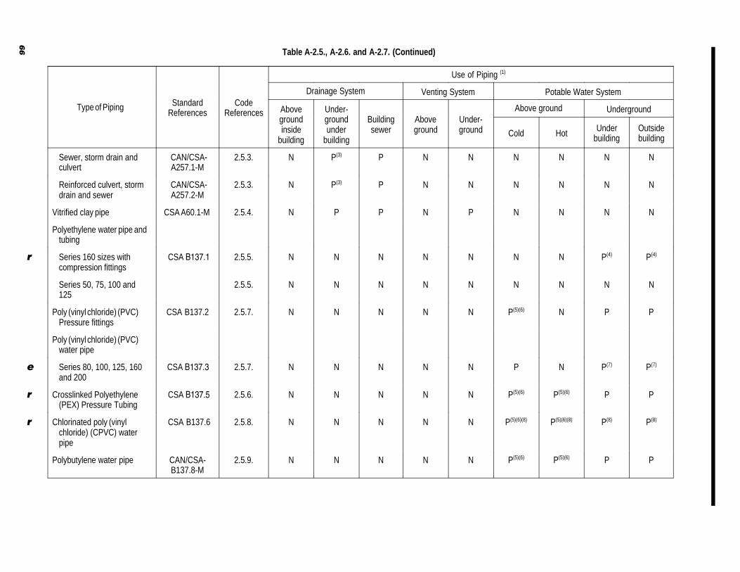
Table A-2.5., A-2.6. and A-2.7. (Continued)
Use of Piping (1)
Drainage System Venting System Potable Water System
Above ground UndergroundType of Piping StandardReferences
CodeReferences Above
groundinside
building
Under-groundunder
building
Buildingsewer
Aboveground
Under-ground Cold Hot Under
buildingOutsidebuilding
Sewer, storm drain andculvert
CAN/CSA-A257.1-M
2.5.3. N P(3) P N N N N N N
Reinforced culvert, stormdrain and sewer
CAN/CSA-A257.2-M
2.5.3. N P(3) P N N N N N N
Vitrified clay pipe CSA A60.1-M 2.5.4. N P P N P N N N N
Polyethylene water pipe andtubing
Series 160 sizes withcompression fittings
r CSA B137.1 2.5.5. N N N N N N N P(4) P(4)
Series 50, 75, 100 and125
2.5.5. N N N N N N N N N
Poly (vinyl chloride) (PVC)Pressure fittings
CSA B137.2 2.5.7. N N N N N P(5)(6) N P P
Poly (vinyl chloride) (PVC)water pipe
Series 80, 100, 125, 160and 200
e CSA B137.3 2.5.7. N N N N N P N P(7) P(7)
Crosslinked Polyethylene(PEX) Pressure Tubing
r CSA B137.5 2.5.6. N N N N N P(5)(6) P(5)(6) P P
Chlorinated poly (vinylchloride) (CPVC) waterpipe
r CSA B137.6 2.5.8. N N N N N P(5)(6)(8) P(5)(6)(8) P(8) P(8)
Polybutylene water pipe CAN/CSA-B137.8-M
2.5.9. N N N N N P(5)(6) P(5)(6) P P
66

Table A-2.5., A-2.6. and A-2.7. (Continued)
Use of Piping (1)
Drainage System Venting System Potable Water System
Above ground UndergroundType of Piping StandardReferences
CodeReferences Above
groundinside
building
Under-groundunder
building
Buildingsewer
Aboveground
Under-ground Cold Hot Under
buildingOutsidebuilding
Polyethylene/Aluminum/Polyethylene (PE/AL/PE)Pressure pipe
CAN/CSA-B137.9-M
2.5.13. N N N N N P(5)(6) N P P
Crosslinked Polyethylene/Aluminum/CrosslinkedPolyethylene (PEX /AL /PEX) Pressure pipe
CAN/CSA-B137.10-M
2.5.14. N N N N N P(5)(6) P(5)(6) P P
Polypropylene (PP-R)Pressure pipe
CAN/CSA-B137.11
2.5.15. N N N N N P(5)(6) P(5)(6) P P
Plastic sewer pipePS ≥ 320 kPa
r CSA-B182.1 2.5.10.(1) N P P N N N N N N
2.5.10. P(5)(6) P P P(5)(6) P N N N NAcrylonitrile-butadiene-styrene (ABS) DWV pipe
r CSA-B181.1
r ABS Schedule 40 DWV pipe ASTM F 628 2.5.10.(1) P(5)(6) P P P(5)(6) P N N N N
2.5.11.
2.5.10. P(5)(6) P P P(5)(6) P N N N NPoly (vinyl chloride) (PVC)DWV pipe
rwith a cellular core
CSA-B181.22.5.11
Type PSM PVC sewer pipe≤ 35-SDR
r CSA-B182.2 2.5.10. N P P N P N N N N
Profile poly(vinylchloride)(PVC) sewer pipe
e PS >_ 320 kPa
r CSA-B182.4 2.5.10.(1)(e) N P P N P N N N N
Profile polyethylene sewere pipe PS >_ 320 kPa
CAN/CSA-B182.6-M
2.5.10.(1)(f) N P P N P N N N N
Polyolefin laboratorydrainage systems
CAN/CSA-B181.3-M
2.8.1. P(5)(6) P P P(5)(6) P N N N N
67
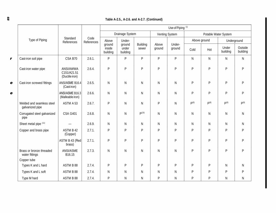
Table A-2.5., A-2.6. and A-2.7. (Continued)
Use of Piping (1)
Drainage System Venting System Potable Water System
Above ground UndergroundType of Piping StandardReferences
CodeReferences Above
groundinside
building
Under-groundunder
building
Buildingsewer
Aboveground
Under-ground Cold Hot Under
buildingOutsidebuilding
Cast-iron soil piper CSA-B70 2.6.1. P P P P P N N N N
Cast-iron water pipe ANSI/AWWAC151/A21.51(Ductile iron)
2.6.4. P P P P P P P P P
e Cast-iron screwed fittings ANSI/ASME B16.4(Cast iron)
2.6.5. N N N N N P P P P
e ANSI/ASME B16.3(Malleable iron)
2.6.6. N N N N N P P P P
Welded and seamless steelgalvanized pipe
ASTM A 53 2.6.7. P N N P N P(9) P(9) P(9) P(9)
Corrugated steel galvanizedpipe
CSA-G401 2.6.8. N N P(10) N N N N N N
Sheet metal pipe (11) — 2.6.9. N N N N N N N N N
Copper and brass pipe ASTM B 42(Copper)
2.7.1. P P P P P P P P P
ASTM B 43 (Redbrass)
2.7.1. P P P P P P P P P
Brass or bronze threadedwater fittings
ANSI/ASMEB16.15
2.7.3. N N N N N P P P P
Copper tube
Types K and L hard ASTM B 88 2.7.4. P P P P P P P N N
Types K and L soft ASTM B 88 2.7.4. N N N N N P P P P
Type M hard ASTM B 88 2.7.4. P N N P N P P N N
68

Table A-2.5., A-2.6. and A-2.7. (Continued)
Use of Piping (1)
Drainage System Venting System Potable Water System
Above ground UndergroundType of Piping StandardReferences
CodeReferences Above
groundinside
building
Under-groundunder
building
Buildingsewer
Aboveground
Under-ground Cold Hot Under
buildingOutsidebuilding
Type M soft ASTM B 88 2.7.4. N N N N N N N N N
Type DWV ASTM B 306 2.7.4. P(12) N N P(12) N N N N N
CSA B158.1 2.7.5. P P P P P N N N NSolder-joint drainage fittings
ANSI/ASMEB16.29
ANSI B16.18 2.7.6. N N N P P P P P PSolder-joint water fittings
ANSI/ASMEB16.22
Lead waste pipe CSA B67 2.7.8. P(5)(6) P N P(5)(6) P N N N N
N — Not permitted P — Permitted
Notes to Table A-2.5., A-2.6. and A-2.7.:(1) Where fire stops are pierced by pipes, the integrity of the fire stop must be maintained.(2) Cold water only.(3) Gasketted joints required.(4) Permitted only for water service pipe.(5) Combustible piping in noncombustible construction is subject to the requirements of Article 3.1.5.15.(1) of the National Building Code 1995.(6) Combustible piping that penetrates a fire separation is subject to the requirements in Articles 3.1.9.1., 9.10.9.6. and 9.10.9.7. of the National Building Code 1995.(7) Not permitted in hot water systems.(8) Not to exceed design temperature and design pressure in Sentence 2.5.8.(2).(9) Permitted only in buildings of industrial occupancy as described in the National Building Code 1995, or the repair of existing galvanized steel piping systems.(10) Permitted underground only in a storm drainage system.(11) Permitted only for an external leader.(12) Not permitted for the fixture drain or vent below the flood level rim of a flush valve operated urinal.
69

A-2.5.3.(3)
A-2.5.3.(3) Concrete Fittings. Concrete fit-tings fabricated on the site from lengths of pipe mayhave proven acceptable on the basis of past perfor-mances in some localities, and their acceptanceunder Article 1.4.3. of this Code may be warranted.
A-2.5.6. (1) Crosslinked Polyethylene Pipeand Fittings. There are some special installationrequirements for the use of crosslinked polyethylenepipe and its associated fittings. Reference should,therefore, be made to the installation information in
r CSA-B137.5, “Cross-linked Polyethylene(PEX) Tubing Systems for Pressure Applications.”
A-2.5.10. to 2.5.12. Solvent Cement. TheCSA standards B181.1, B181.2 and B137.6 ref-erence ASTM standard D 3138, which specifies thecolour of the solvent cement. PVC cement shall begrey, ABS cement shall be yellow, CPVC cementshall be clear and transition cement shall be white.The standard colour allows code users to readilydetermine if the correct solvent cement has beenused. It should be noted that a transition cement isnot an all-purpose cement.
A-2.5.13.(1) Polyethylene/Aluminum/Poly-ethylene Composite Pipe and Fittings. Thereare some special installation requirements for theuse of polyethylene/aluminum/polyethylene com-posite pipe and fittings. Reference should, therefore,be made to the installation information inCAN/CSA-B137.9-M, “Polyethylene/Aluminum/Polyethylene Composite Pressure Pipe Systems.”
A-2.5.14.(1) Crosslinked Polyethylene/Alu-minum/Crosslinked PolyethyleneComposite Pressure Pipe and Fittings.There are some special installation requirements forthe use of crosslinked polyethylene/aluminum/crosslinked polyethylene composite pipe and fit-tings. Reference should, therefore, be made to theinstallation information in CAN/CSA-B137.10-M,“Crosslinked Polyethylene/Aluminum/CrosslinkedPolyethylene Composite Pressure Pipe Systems.”
A-2.5.15.(1) Polypropylene Pipe andFittings. There are some special installation re-quirements for the use of polypropylene pipe andfittings. Reference should, therefore, be made to theinstallation information in CAN/CSA-B137.11,“Polypropylene (PP-R) Pipe and Fittings forPressure Applications.”
A-2.6.7.(3) Galvanized Steel Pipe. The useof galvanized steel pipe and fittings in a water dis-
tribution system may have proven acceptable on thebasis of past performance in some localities, and itsacceptance under Article 1.4.3. of this Code may bewarranted.
A-2.7.9.(3) Example of Acid and AlkaliContaining Waste. A commercial dishwasher isa typical example of an installation which dis-charges acid and alkali containing waste above 60�C.
A-2.10.5. Saddle Hubs or Fittings. Saddlehubs or fittings may have proven acceptable on thebasis of past performance in some localities, andtheir acceptance under Article 1.4.3. of this Codemay be warranted.
A-2.10.9.(3) Bubblers. Bubblers installed onother than drinking fountains may have proven ac-ceptable on the basis of past performance in somelocalities, and their acceptance under Article 1.4.3.of this Code may be warranted.
A-3.3.10. Linear Expansion e
Figure A-3.3.10.
Linear Expansion
70
Temperature change, °C

A-4.2.1.(1)(a) and (e)
sanitary building drain
air break
COgreaseinterceptor
sink glas
s fil
ler
ice
crea
m s
coop
sco
ffee
drip
s
frig
.fo
odco
mpa
rtm
ent
food display
CO
air break
discharge fromrelief valve
soil-or-waste stackDF
DF
DF
leader
sterilizer(clear water waste)
air break
installationof backwatervalverecommended
RD
Extended to open airwhen fixtures on 3 ormore storeys connected
stormbuildingdrain
CO
trap for leader
Serves receptaclesdraining indirectconnections
FD
max height300 mm
Figure A-4.2.1.A.
Indirect Connections
73

A-4.2.1.(2)
A-4.2.1.(2) Soil-or-Waste Pipe Connections
1.5 m
branch orbuilding drain
(b) Connection to nominally horizontal(b) soil-or-waste pipe
no soil-or-wastepipe to connectin this area
soil-or-wastestack
(a) Connection to nominally (a) horizontal offset
soil-or-waste stack
1.5 m
no soil-or-wastepipe to connectin this area
soil-or wastestack
horizontaloffset
Figure A-4.2.1.B.
Soil-or-Waste Pipe Connections
A-4.4.3.(1) Grease Interceptors. Grease in-terceptors may be required when it is consideredthat the discharge of excessive grease may impairthe drainage system. Information on the design andsizing of grease interceptors can be found in ASPE
e Data Book- Volume 1, Chapter 35, GreaseInterceptors.
A-4.5.1.(2) Trapping of Sinks and LaundryTrays
3 compartment sink
fitting and trap onesize larger than largestwaste outlet pipe(Sentence 4.9.3.(2))
(a)
* developed length not to exceed 900 mm (Article 4.8.2.)
*
*
2 compartment sink
* developed length not to exceed 900 mm (Article 4.8.2.)
(b)
*
sinksink
(c)
sink
developed length notto exceed 900 mm
Figure A-4.5.1.A.
Trapping of Sinks and Laundry Trays
74
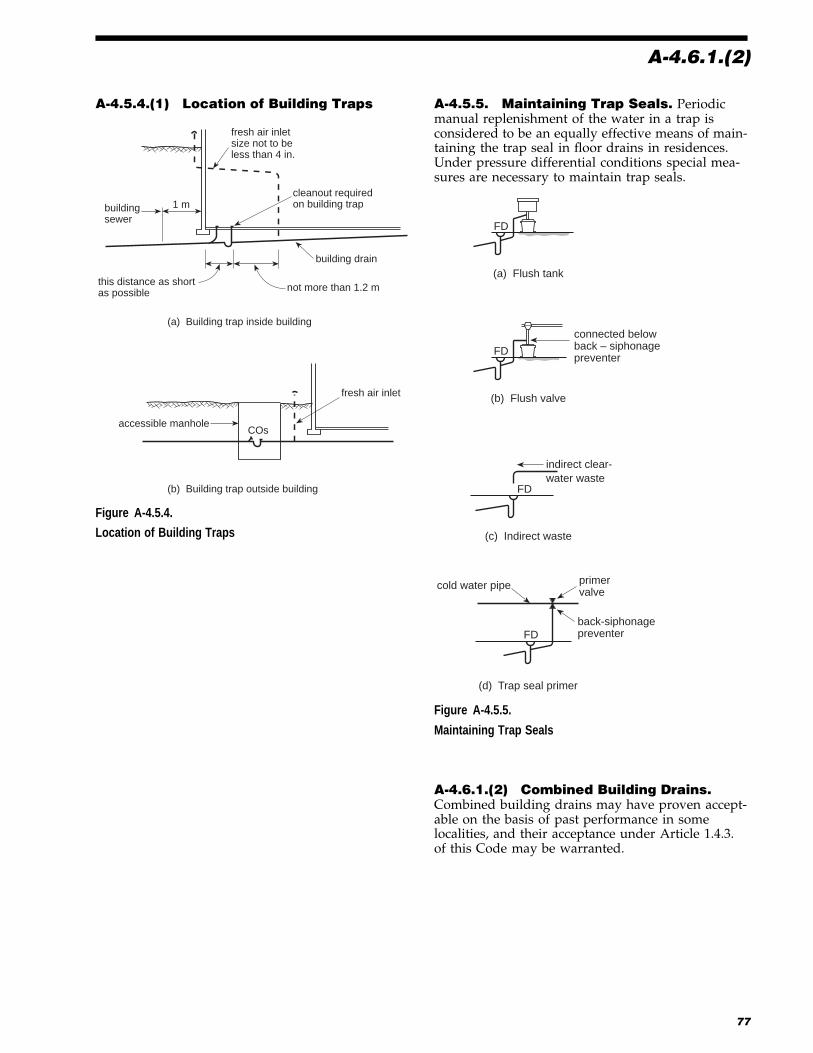
A-4.6.1.(2)
A-4.5.4.(1) Location of Building Traps
fresh air inletsize not to beless than 4 in.
cleanout requiredon building trap1 mbuilding
sewer
this distance as shortas possible
building drain
not more than 1.2 m
(a) Building trap inside building
COs
fresh air inlet
accessible manhole
(b) Building trap outside building
Figure A-4.5.4.
Location of Building Traps
A-4.5.5. Maintaining Trap Seals. Periodicmanual replenishment of the water in a trap isconsidered to be an equally effective means of main-taining the trap seal in floor drains in residences.Under pressure differential conditions special mea-sures are necessary to maintain trap seals.
FD
(a) Flush tank
FD
(b) Flush valve
connected belowback – siphonagepreventer
(c) Indirect waste
FD
indirect clear-water waste
FD
(d) Trap seal primer
cold water pipe primervalve
back-siphonagepreventer
Figure A-4.5.5.
Maintaining Trap Seals
A-4.6.1.(2) Combined Building Drains.Combined building drains may have proven accept-able on the basis of past performance in somelocalities, and their acceptance under Article 1.4.3.of this Code may be warranted.
77
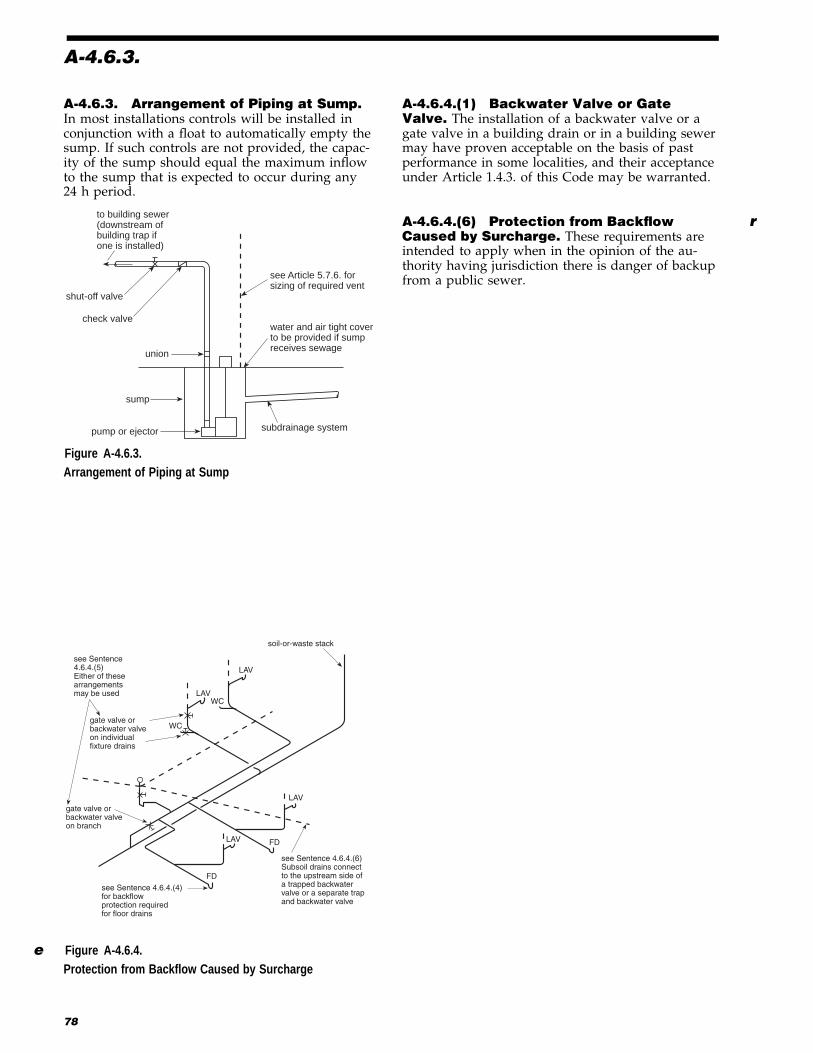
A-4.6.3.
A-4.6.3. Arrangement of Piping at Sump.In most installations controls will be installed inconjunction with a float to automatically empty thesump. If such controls are not provided, the capac-ity of the sump should equal the maximum inflowto the sump that is expected to occur during any24 h period.
to building sewer(downstream ofbuilding trap ifone is installed)
shut-off valve
check valve
union
sump
pump or ejector
see Article 5.7.6. forsizing of required vent
water and air tight coverto be provided if sumpreceives sewage
subdrainage system
e Figur e A-4.6.3.Arrangement of Piping at Sump
A-4.6.4.(1) Backwater Valve or GateValve. The installation of a backwater valve or agate valve in a building drain or in a building sewermay have proven acceptable on the basis of pastperformance in some localities, and their acceptanceunder Article 1.4.3. of this Code may be warranted.
A-4.6.4.(6) Protection from Backflow rCaused by Surcharge. These requirements areintended to apply when in the opinion of the au-thority having jurisdiction there is danger of backupfrom a public sewer.
e Figur e A-4.6.4.Protection from Backflow Caused by Surcharge
78
soil-or-waste stack
LAV
WCLAV
WC
see Sentence4.6.4.(5)Either of thesearrangementsmay be used
gate valve orbackwater valveon branch
LAV
FDLAV
FDsee Sentence 4.6.4.(4)for backflowprotection requiredfor floor drains
see Sentence 4.6.4.(6)Subsoil drains connectto the upstream side ofa trapped backwatervalve or a separate trapand backwater valve
gate valve orbackwater valveon individualfixture drains

A-4.10
FSDF
WC
UR
WC
LAV
FD
LAV
WCFDWC
typical
LAV
WC 3 in. FDs FS
Semi-continuous flow0.23 L/s
ditto ditto
ditto ditto
ditto ditto
ditto ditto
RD RD
roof 18 m x 30 m
Building drainage system (Example II)
Figure A-4.10.D.
Building Drainage System (Example 2)
83

A-4.10
F. Size of Horizontal Leaders
Table 4.10.9. @ 1 in 25, a 4-in. pipe will carry a loadof 8 430 L Code of Canada 1995.
Table 4.10.9. @ 1 in 100, a 5-in. pipe will carry aload of 7 650 L
Table 4.10.9. @ 1 in 133, a 6-in. pipe will carry aload of 10 700 L
Therefore use a 5-in. pipe at a slope of 1 in 100.
G. Size of Vertical Leader
Table 4.10.11. would permit a 5-in. pipe (19 500 L)but they are not readily available. For practical rea-sons use a 6-in. pipe.
H. Size of Storm Building Drains
Since a drainage pipe cannot be smaller than anyupstream pipes, the storm building drain must be atleast 6 in. Referring again to Table 4.10.9., a 6-in.pipe will carry a hydraulic load of 17 600 L at aslope of 1 in 50. Therefore use a 6-in. pipe at aslightly higher slope.
I. Size of Combined Building Sewer(a) Total sanitary load excluding semi-
continuous flow 261 fixture unitsconverted to litres(Clause 4.10.5.(1)(b)) � 9.1 = 2 375 L
(b) Semi-continuous flow 0.23 L/s convertedto litres(Sentence 4.10.3.(2)) � 900 = 207 L
(c) Storm load 15 120 LTotal hydraulic load 17 702 L
Referring to Table 4.10.9. @ 1 in 50, a 6-in. pipe willcarry 17 600 L
Referring to Table 4.10.9. @ 1 in 25, a 6-in. pipe willcarry 24 900 L
Therefore use a 6-in. pipe at a slope of not less than1 in 32.
A-4.10.4.(1) Rainfall Intensities. Climate in-formation on rainfall intensities for various citiescan be found in Appendix C of the National Building e
When calculating the hydraulic load from a roof orpaved surface, it should be noted that 1 mm depthof water on 1 m2 of surface is equivalent to 1 L.
A-5.1.1.(3) Trapping of Floor Drains
A
3 in. or largerfloor draintrap
fixture drainor trap armsoil-or-
waste stack
(a)
A
fixture drainor trap arm
3 in. or largerfloor draintrap
building drain, branchor nominally horizontaloffset in a soil-or-wastestack
Length of "A" must be at least450 mm and its fall shall notexceed the size of the pipe
See also explanation ofSentence 5.6.3.(1) forfall on fixture drain
(b)
Figure A-5.1.1.A.
Trapping of Floor Drains
84

A-5.2.1.
A-5.1.1.(4) Venting not Required
subsoil drainage pipe
basement
COs sanitary building drain
vent not requiredfor trap servingsubsoil drainage pipe
(a)
leader
storm buildingdrain
COvent not required for trapserving a storm drainagesystem
sanitary building drain
combined building sewer
(b)
vent not required fortraps which form partof an indirect drainagesystem
This trap to be ventedin an approved manner
(c)
Figure A-5.1.1.B.
Venting not Required
A-5.2.1. Single Storey Wet Venting. Eachsection of a single storey wet vent is sized accordingto the total load it serves (see Article 5.8.1.). Sepa-rately vented fixtures may connect to a wet vent.
Fixture drains are connected separately and directlyinto the branch or soil-or-waste stack in confor-mance with Article 5.6.3.
Figure (d) shows that water closets are connecteddownstream of all other fixtures when connected toa vertical pipe.
Figur e A-5.2.1. eSingle Storey Wet Venting
85
WC
WC
separatelyventedfixture
buildingdrain, branch oroffset in soil-or-waste stack
(a)
WC WC
(b)
LAV
bathbranch
doublefitting
LAV
bath
(c)
separatelyventedfixture
building drainor branch
(d)
separatelyventedfixture
A double fittingwith side inletsmay be used here
branch orsoil-or-wastestack

A-5.2.2.(1) and (2)
A-5.2.2.(1) and (2) Single Storey WetVenting with Relief Vents
URsFD
UR
WCs
continuous vent
buildingdrain
relief ventnot required
Water closets do nothave to be downstreamof the other fixtures
(a)
continuous vent
branch
relief ventnot required
(b)
These wall outletfixtures do not haveto be of the same type
6 WCs
continuous vent
relief ventnot required
(c)
6 fixture unitsor less
soil-or-waste stack,branch orbuildingdrain
wet vent
continuous vent
(d)
45° change in direction
A relief vent is requiredsince the cumulativechange in directionexceeds 45°
branch or building drain
continuousvent
(e)
wet vent
reliefvents
maximum of 8fixture drainsbetweenvents
max. 2 in(see 5.2.1.(2))
Separately ventedfixture(s) may beconnected to awet vent
a relief vent is requiredsince there are over 6 fixtureunits connected to thesoil-or-waste stack,branch or building drain
continuousvent
(f)
over 6fixtureunits
soil-or-waste stack,branch or buildingdrain
wet vent
this branch to be alsosized as a wet vent
continuousvent servingas the requiredrelief vent
a relief vent is requiredsince there are over 6 fixtureunits connected to thesoil-or-waste stack,branch or building drain
over 6fixtureunits
Figure A-5.2.2.A.
Single Storey Wet Venting with Relief Vents
86

A-5.8
e Figur e A-5.8.
Sizing of a Venting System
Note to Figure A-5.8.:(1) Letters in Table A-5.8.B. Vent Pipe Sizes refer to corresponding letters on this diagram.
93
sump vent
branch
WC
branch vent
Rheader
stackvent
LAVs
branch vent
LAVscontinuous vent
BG
continuousvent
soil-or-wastestackNo. I
header
vent stackstackvent
BG
individualvent
LAVLAVsK
L dual vent
soil-or-wastestackNo. II
continuousvent
BGH
O
N
J
Q
BG
continuous vent
LAVs
branch ventLAVs
FDF GE
5 WCs Dcontinuous vent
vent stackKS BG11/2
vent stack
A
continuous vent
branch vent
sewage sump
Hydraulic loads shown thus 6
6 6 2 2 2
1.5 m
1.8 m
5.5 m 6.1 m
2.1 m
15.2 m
k
h
1 1 1 1
2
j
WCs URs
0.9 m
6
1.5 m 0.9 m
6.1 m
P
111
2.4 m 4.6 m
0.9 m
3.0 m
Mg6.1 m
6f
e
6.1 m
d
2.7 m
branch vent
6
1.8 m
0.6 m
5.5 m
3.0 m
11116
3
6
B
4.6 m
1.8 m
0.6 m 4"
C9.1 m
4"
c
ba
6
61LAV
6.1 m

A-5.8
Table A-5.8.AItems to Consider When Sizing Vent Pipes
Type of Vent Code Reference Items to Consider When Sizing Vent Pipes
Branch vent 5.8.3.(1)Table 5.8.3.5.8.3.(4)Table 5.7.1.
Number of fixture units vented by the section of branch ventLength
Continuous vent Table 5.8.3. Size of trap servedNumber of fixture units ventedLength
Dual vent 5.8.2.Table 5.7.1.
Size of largest trap vented onlyLength is not considered
e Fresh air inlet 5.5.4. Minimum size 4 in.
Header 5.8.3.(1)Table 5.8.3.5.8.3.(4)Table 5.7.1.
Number of fixture units vented by the section of headerLength
Individual vent 5.8.2.Table 5.7.1.
Size of largest trap vented onlyLength is not considered
Manhole vent 5.7.5. Minimum 2 in. inside a building
Oil interceptor vent 5.7.7.5.5.2.(1) and (2)
Minimum size 2 in.
Relief vent 5.7.3.(1) One size less than the continuous vent or stack vent
Sewage sump vents 5.5.1.5.7.6.(1) and (2)
One size less than largest inlet to sumpMinimum 2 in. maximum 4 in. vent
Stack vent 5.8.4.(1)Table 5.8.3.5.4.1.(1) and (2)
Number of fixture units draining to base of stackLength of stack ventTable 5.7.1.
Vent stack 5.8.4.(1)Table 5.8.3.5.8.4.(2)Table 5.7.1.5.4.2.(1) and (2)
Number of fixture units draining to base of stackLength of vent stackNumber of storeys draining to stack
Wet vent 5.8.1.(1)Table 5.8.1.5.2.5.3.
Whether water closets are served by the wet ventNumber of fixture units other than water closets which drain to the wetventTrap size other than water closets and emergency floor drains not toexceed 2 in.If wet vent exceeds 2 storeys in height, no more than 4 fixture unitspermitted per storey above the second storeyLength of any offset in wet vent
94

A-5.8
Table A-5.8.B.Vent Pipe Sizes
Vent Pipe Developed Length Used toDetermine Size, m
HydraulicLoad Used to
DetermineSize, fixture
units
Code Reference to beConsidered
MinimumSize, in.
Continuous vent (ac) 32.9 (acegjl) 7 5.7.1. 5.8.3.(2) 25.8.3.(1)
Sump vent (bc) N/A 7 5.7.6. 2 1/2Branch vent (ce) 32.9 (acegjl) 7 5.7.1. 5.8.3.(1) 2 1/2
5.7.2. 5.8.3.(3)
Continuous vent (de) 20.4 (degjl) 6 5.7.1. 5.8.3.(2) 1 1/25.8.3.(1)
Branch vent (eg) 32.9 (acegjl) 13 5.7.1. 5.8.3.(1) 2 1/25.7.2. 5.8.3.(3)
Continuous vent (fg) 17.7 (fgjl) 6 5.7.1. 5.8.3.(2) e1 1/25.8.3.(1)
Branch vent (gj) 32.9 (acegjl) 19 5.7.1. 5.8.3.(1)e 2 1/25.7.2. 5.8.3.(3)
Continuous vent (hj) 7.6 (hjl) 22 5.7.1. 5.8.3.(1) 1 1/25.8.1.
Branch vent (jl) 32.9 (acegjl) 41 5.7.1. 5.8.3.(3) e2 1/2 5.8.3.(1)
Stack vent (kl) 4.2 (klQR) 36 5.7.1. 5.8.4.(2) 25.8.4.(1) 5.8.4.(3) e
Stack vent (lQ) 4.2 (klQR) 43 5.7.1. 5.8.4.(1) e25.7.2. 5.8.4.(2)
Vent Stack 37.3 (ABCGJNPQR) 591/2 4.9.1. 5.8.1.(1) 3
1/2
Section (ABCGJNP) 5.4.2.(3) 5.8.4.(1)
5.7.1. 5.8.4.(2)
Continuous vent (DF) 6.1 (DFG) 32 5.7.1. 5.8.3.(1) 1 1/25.8.1.(1)
Continuous vent (EF) N/A 34 5.2.2.(2) 5.7.3. 1 1/25.7.1.
Branch vent (FG) 6.1 (DFG) 34 5.7.1. 5.8.3.(3) 1 1/25.8.3.(1)
Continuous vent (HJ) 1.8 (HJ) 6 5.7.1. 5.8.3.(2) 1 1/25.8.3.(1)
Individual vent (KM) N/A 1 5.7.1. 1 1/4Dual vent (LM) N/A 2 5.7.1. 1 1/4Branch vent (MN) 7.0 (KMN) 3 5.7.1. 5.8.3.(3) 1 1/4
5.8.3.(1)
Stack vent (OP) 19.1 (OPQR) 591/2 5.7.1. 5.8.4.(2) 21/25.8.4.(1)
Header (PQ) 37.3 (ABCGJNPQR) 591/2 5.7.1. 5.8.3.(4) 35.8.3.(1)
Header (QR) 37.3 (ABCGJNPQR) 1021/2 5.6.5.(5) 5.8.3.(1) 3 e5.7.1. 5.8.3.(4) e
95

A-5.8.1.(1)
A-5.8.1.(1) Sizing of Single Storey WetVent Systems
stack ventor continuousvent
(a)
nominally horizontalsoil-or-waste pipe
(b)
WC
3"
2"LAV
1 1/2"
BT
2" LAV
WC
stack ventor continuousvent
WC LAVLAV
BT
WC3"
1 1/2"
branch or soil-or-waste stack
stack vent orcontinuous vent
(c)
nominally horizontalsoil-or-waste pipe
2 1/2"
2"
BT
2"
LAV
BT
BT
BT
LAV
2 1/2"
1 1/2"
stack vent orcontinuous vent
(d)
nominally horizontalsoil-or-waste pipe
LAV
BT1 1/2"
WC
3" 2"
BT
BT
Figure A-5.8.1.A.
Sizing of Single Storey Wet Vent Systems
A-5.8.1.(2) Sizing of Multi-Storey Wet VentSystems
stackvent
wet ventportion
soil-or-waste stack
These fixtures are notincluded when determiningthe size of the wet ventportion by Table 5.8.1.B.
(a)Not serving water closets
stackvent
wet ventportion
soil-or-waste stack
These fixtures are notincluded when determiningthe size of the wet ventportion by Table 5.8.1.B.
(b)Serving water closets
May serve1 or 2water closets
Figure A-5.8.1.B.
Sizing of Multi-Storey Wet Vent Systems
96

A-6.1.1.(1)
A-5.8.3. and 5.8.4. Lengths to beConsidered When Sizing Vent Pipes
Dual vent AC
Continuous vent BC
Individual vent DE
Dual vent FG
Branch vent CEGH
n/a
BCEGH 1.8 + 1.2 + 0.6 + 2.1 + 1.8 = (7.5)
n/a
n/a
ACEGH 2.4 + 2.7 + 0.6 + 2.1 + 1.8 = (9.6)
5.8.2.
5.8.3.
5.8.2.
5.8.2.
5.8.3.
Length to be consideredVent Reference
(a)
A
1.8 m
continuousvent
2.7 m
2.4 m
dualvent
B
D
F
G
EC1.2 m
0.6 m
2.1 m
1.8 m
stackvent
branchvent
H
dual vent
individual vent
Figure A-5.8.3.A.
Lengths to be Considered When Sizing Vent Pipes (Isometric View)
Vent stack (AC)
Vent stack (BC)
Vent stack (HI)
Stack vent (DE)
Stack vent (FG)
Stack vent (JK)
Header (CEGIKL)
ACEGIKL
BCEGIKL
HIKL
DEGIKL
FGIKL
JKL
ACEGIKL
5.8.4. (2)
5.8.4. (2)
5.8.4. (2)
5.8.4. (2)
5.8.4. (2)
5.8.4. (2)
5.8.3. (4)
Vent pipe Length to be considered Reference
(or any section of it)
branchvent
branchvent
branch
stack vent
branchvent
branch
branchvent
branchvent
branch
roof
building drain or branch
L
K I
J
H
G E
F
B A
D
C
(b)
header
Figure A-5.8.3.B.
Lengths to be Considered When Sizing Vent Pipes
A-6.1.1.(1) Potable Water Systems. The de-sign procedures contained in the ASHRAE
e Handbook- HVAC Applications, Chapter 44; ine ASPE Data Book- Volume 1, Chapter 3, Cold Watere Systems; and in ASPE Data Book- Volume 1,
Chapter 4, Service Hot Water Systems; areconsidered good engineering practice in the field ofpotable water systems.
As an alternative, the following procedures may beused in determining the size of each section of the
water system using Table A-6.1., which incorporatesthe requirements of Sentence 6.3.2.(3).
(1) Determining Conditions. On a proposedwater piping installation sized pursuant to Table A-6.1. the following conditions need to be determined:
(a) total number of fixture units as deter-mined from Tables 6.3. and 6.3.2. for thefixtures to be installed;
(b) developed length of the pipe from prop-erty line to most remote outlet, or if thepressure at the property line or meter is
97

A-6.1.1.(1)
unknown, the developed length from thepublic water main to most remote outlet;
(c) difference in elevation between the waterpiping at the property line or othersource of supply and the highest fixtureor outlet;
(d) pressure in the public water main orother source of supply at the localitywhere the installation is to be made; (thispressure may need to be reduced so thatthe pressure in the water distributionsystem does not exceed 550 kPa)
(e) in localities where there is a wide fluctu-ation of pressure in the main throughoutthe day, the minimum pressure avail-able, which is used as a basis for design.
(2) Water Service Pipe. Beginning with theavailable pressure at the property line, public watermain or other source of supply, and subtracting10 kPa for each metre of difference in elevation be-tween such source of supply and the highest wateroutlet in the building or on the premises, use the“Pressure Range” group in Table A-6.1. withinwhich this adjusted pressure falls. Select the “lengthcolumn” which is equal to or longer than the re-quired length of service pipe. Follow down thecolumn to a fixture unit equal to or greater than thetotal number of fixture units required by the instal-lation. Having located the proper fixture unit valuefor the required length, locate the size of the waterservice in the left hand column.
(3) Cold Water Piping. Starting at the mostremote outlet on the cold water piping and workingback toward the water service or meter, using thetotal developed length of pipe, compute the pipesizing for the system, using the total fixture unitvalues given in Tables 6.3. and 6.3.2. and adding inthe fixture unit demand of the hot water supply in-
let at the point where it occurs. The final size of thecold water service need not be larger than the sizerequired by Table A-6.1. for the water service.
(4) Hot Water Piping. Starting at the mostremote outlet on the hot water piping and workingback toward the service water heater, compute thepipe sizing for the system from the length columnselected in Table A-6.1. using the fixture unit valuesgiven in Tables 6.3. and 6.3.2.
Example: Sizing the Water Pipe in a Four-UnitApartment Building
Figures A-6.1.1.A. and A-6.1.1.B. illustrate the coldand hot water supply piping for a four-unit apart-ment building. Each apartment has a kitchen sink, aflush tank water closet, a lavatory and a bathtub.The water heater and a laundry room with one ser-vice sink and two automatic clothes washers arelocated in the basement of the apartment building.
For the purpose of this example, the following con-ditions are assumed:(a) water pressure at the meter is 413 kPa,(b) developed length of the cold water piping
from the property line to the most remote coldwater outlet is 18 m,
(c) the elevation (head) difference between theproperty line and the highest water supplyoutlet is 3.65 m.
Step 1A. The cold water supply fixture unit (cwsfu)demand for the entire building is calculated as fol-lows from the “Private Use” column of Table 6.3.(The numbers in squares at each fixture or sectionof pipe indicate the water supply fixture unit de-mand at that location.)
98

A-6.1.1.(1)
Table A-6.1.Pipe Sizes for Water Systems Based on Number of Fixture Units Served (1)
Maximum allowable length, mWater
Service,in.
WaterDistributionSystem,
in.12 18 24 30 46 61 76 91 122 152 183 213 244 274 305
Pressure range Number of Fixture Units Served
200 to 310 kPa3/4 1/2 6 5 4 3 2 1 1 1 0 0 0 0 0 0 03/4 3/4 18 16 14 12 9 6 5 5 4 4 3 2 2 2 13/4 1 29 25 23 21 17 15 13 12 10 9 7 6 6 6 6
1 1 36 31 27 25 20 17 15 13 12 10 8 6 6 6 6
1 1 1/4 54 47 42 38 32 28 25 23 19 17 14 12 12 11 11
1 1/2 1 1/4 90 68 57 48 38 32 28 25 21 18 15 12 12 11 11
1 1/2 1 1/2 151 124 105 91 70 57 49 45 36 31 26 23 21 20 20
2 1 1/2 210 162 132 110 80 64 53 46 38 32 27 23 21 20 20
1 1/2 2 220 205 190 176 155 138 127 120 104 85 70 61 57 54 51
2 2 372 329 292 265 217 185 164 147 124 96 70 61 57 54 51
2 2 1/2 445 418 390 370 330 300 280 265 240 220 198 175 158 143 133
311 to 413 kPa3/4 1/2 9 7 6 5 4 3 2 2 1 1 1 0 0 0 03/4 3/4 27 23 19 17 14 11 9 8 6 5 4 4 3 3 33/4 1 44 40 36 33 28 23 21 19 17 14 12 10 9 8 8
1 1 60 47 41 36 30 25 23 20 18 15 12 10 9 8 8
1 1 1/4 102 87 76 67 52 44 39 36 30 27 22 20 19 17 16
1 1/2 1 1/4 156 130 106 89 66 52 44 39 33 29 24 20 19 17 16
1 1/2 1 1/2 270 225 193 167 128 105 90 78 62 52 42 38 35 32 30
2 1 1/2 286 286 242 204 150 117 98 84 67 55 42 38 35 32 30
1 1/2 2 360 360 340 318 272 240 220 198 170 150 135 123 110 102 94
2 2 570 510 470 430 368 318 280 250 205 165 142 123 110 102 94
2 2 1/2 680 640 610 580 535 500 470 440 400 365 335 315 285 267 250
Over 413 kPa3/4 1/2 11 9 7 6 5 4 3 3 2 1 1 1 1 1 03/4 3/4 31 28 24 22 17 13 11 10 8 7 6 6 5 4 43/4 1 63 53 47 42 35 30 27 24 21 17 14 13 12 12 11
1 1 72 66 55 48 38 32 29 26 22 18 14 13 12 12 11
1 1 1/4 140 126 108 96 74 62 53 47 39 31 26 25 23 22 21
1 1/2 1 1/4 156 156 150 127 93 74 62 54 43 34 26 25 23 22 21
1 1/2 1 1/2 286 286 273 240 186 154 130 113 88 73 51 51 46 43 40
2 1 1/2 286 286 286 275 220 170 142 122 98 82 64 51 46 43 40
1 1/2 2 360 360 360 360 360 335 305 282 244 212 187 172 153 141 129
2 2 611 611 610 560 478 420 375 340 288 245 204 172 153 141 129
2 2 1/2 690 690 690 690 690 650 610 570 510 460 430 404 380 356 329
Notes to Table A-6.1.:(1) Branch pipes up to 7 m developed length (from main to outlet or fixture) may supply maximum of 4 fixture units for half-inch size and maximum
16 fixture units for three-quarter inch nominal size.
99

A-6.1.1.(1)
3
autowashers
41 1"
meter
valve
3/4"
1/2"
1"
1/2"
1/2"
1/2"
3/4"
3/4"
8
16
70
8
2BT
WC
LAV
KS
SS
KS
LAVWC
BT
3
1
2
2
1
3
2
1/2" 3/4"
1"
1"
3/4"
1/2"
1/2"
1/2"
1/2"3/4"
1"
3
3
3
BT
WC
LAV
KS
2
3
1
2
9
8
45
54BT
WCLAV
KS2
1
28
valve
water heater
Apartment 2
Apartment 4
Apartment 3
Apartment 1
16
29
Figure A-6.1.1.A.
Cold Water Supply Pipe Sizing for a Four-Unit Apartment Building
autowashers
1/2"
1/2"3/4"
1/2"
1/2"
1/2"
3/4"
1/2"
5
10
5
2BT
LAV
KS
SS
KS
LAV
BT
1
2
2
1
2
1/2" 3/4"
3/4"
1/2"
1/2"
1/2"
1/2"1/2"
1"
3
3
3
BT
LAV
KS
2
1
2
9
5
19
10BT
LAV
KS2
1
25
water heater
Apartment 2
Apartment 4
Apartment 3
Apartment 1
10
1/2"
29
e Figur e A-6.1.1.B.
Hot Water Supply Pipe Sizing for a Four-Unit Apartment Building
100

A-6.1.1.(1)
Each apartment has:
1 kitchen sink 2 cwsfu
1 water closet 3 cwsfu
1 lavatory 1 cwsfu
1 bathtub 2 cwsfu
Total cwsfu each apartment 8 cwsfu
� 4 apts.
32 cwsfu
1 service sink 3 cwsfu
2 automatic clothes washers
at 3 cwsfu each 6 cwsfu
Total cwsfu demand of building 41 cwsfu
Step 1B. The hot water supply fixture unit (hwsfu)demand for the entire building is calculated as fol-lows from the “Private Use” column of Table 6.3.
Each apartment has
1 kitchen sink 2 hwsfu
1 lavatory 1 hwsfu
1 bathtub 2 hwsfu
Total each apartment 5 hwfsu
� 4 apts.
20 hwsfu
1 service sink 3 hwsfu
2 automatic clothes washers
at 3 hwsfu each 6 hwsfu
Total hwsfu demand of building 29 hwsfu
This demand of 29 hwsfu is assigned to the waterheater in Figures A-6.1.1.A. and A-6.1.1.B.
Step 2. The developed length is given as 18 m.
Step 3. The elevation (head difference is given as3.65 m).
10 kPa� 3:65 = 36:5 kPa
Step 4. The available pressure is given as 413 kPa.
413� 36:5 = 376 kPa
Step 5. A building with 376 kPa static water pres-sure is sized from the second portion of Table A-6.1.– the 311 to 413 kPa pressure range.
Step 6. The water piping for this entire building willbe sized from the 18 m column of the 311 to413 kPa pressure range portion of Table A-6.1.
Step 7. The size of the water service is determined tobe 1-in. pipe because the cold water supply fixtureunit value calculated in Step 1A (41 cwsfu) falls be-tween the 40 and 47 fixture unit values on the chart,and the higher 47 fixture unit value must be used.
Step 8. The size of the building supply pipe is alsodetermined to be 1 in. from this same line of theTable.
Step 9. Since the fixtures in apartment 3 are most re-mote from the water service pipe, the sizing willbegin in apartment 3 and proceed back toward thewater service pipe.
With a demand of 8 cwsfu on the pipe supplyingthe cold water to apartment 3, it is sized as three-quarter inch pipe. However, the individual fixturesin apartment 3 are all supplied with half-inch fix-ture branch piping. (The sizing of the cold waterpiping of the other 3 individual apartments is iden-tical to that of apartment 3.)
At the point where the apartment 3 cold water sup-ply joins the apartment 4 supply, the pipe serves ademand of 16 cwsfu. However, it does not increasein size, since a three-quarter inch pipe will supply 23cwsfu. (This sizing also applies to the point wherethe cold water supplies for apartments 1 and 2 join.)
A three-quarter inch pipe will adequately serve the9 cwsfu demand of the service sink and two auto-matic clothes washers located in the basementlaundry room.
Step 10. The hot water supply fixture unit demandof the water heater is 29 hwsfu (as calculated in Step1), which requires a 1-in. cold water supply pipe.
Step 11. At the point where the cold water supplyto the water heater is taken from the cold watermain, the cold water supply fixture unit demand in-creases to 45 cwsfu and the table indicates that thepipe size is 1 in.
Step 12. Referring to Figure A-6.1.1.B (which illus-trates the sizing of the hot water piping in the4-unit apartment building of this example), the siz-ing begins in apartment 1, which is the apartmentmost remote from the water heater. A half-inch sizebranch pipe will adequately serve the 3 fixtures inthis apartment that require a hot water supply. (Ahalf-inch pipe serves the other 3 apartments’ hotwater needs as well.)
101

A-6.1.1.(1)
At the point where the hot water supply to apart-ments 1 and 2 joins the hot water main, the pipingis increased to three-quarter inch. This same three-quarter inch pipe is also large enough to supply thecombined 19 hwsfu demand of apartments 1 and 2plus the basement laundry room.
The 9 hwsfu demand of the laundry room fixturesrequires only a three-quarter inch size branch pipe.
The sizing of the hot water supply piping to apart-ments 3 and 4 is identical to that for apartments 1and 2.
At the point where the hot water supply pipe forapartments 1 and 2 and the laundry room joins thesupply to apartments 3 and 4, the pipe is increasedto 1-in. size. The 1-in. size pipe is continued back tothe hot water outlet of the heater.
A-6.1.7.(6) Relief Valves. If the discharge pip-ing is longer than 2 m or more than two 90� elbowsare used, the valve manufacturer’s installation in-structions should be followed to ensure that thepiping does not affect the relief valves’ dischargecapacity.
A-6.1.9. Water Hammer Prevention. Waterhammer is a buildup of pressure in a length of hori-zontal or vertical pipe which occurs when a valveor faucet is closed suddenly. The longer the pipeand the greater the water velocity the greater is thepressure exerted on the pipe, which can be manytimes the normal static water pressure and be suffi-cient to burst the pipe. Ordinary kitchen andbathroom faucets can be closed quickly enough tocause water hammer even with relatively low waterpressure in the pipe.
Means of preventing water hammer should beinstalled wherever there are valves or faucets, par-ticularly where they are at the end of long lengthsof pipes. This may be done by installing either wa-ter hammer arresters which are manufactured forthe purpose or air chambers installed vertically thatare fabricated from pieces of piping with a closedupper end and connected to the end of the horizon-tal or vertical run of pipe.
The air chamber should be 300 to 450 mm long ifmade from the same size pipe as the water pipe itserves. If the chamber is made from a pipe withlarger diameter than the water pipe, its length canbe reduced accordingly.
Air chambers should be accessible if they are themanufactured type with top air valve and a stop-and-waste valve or are of the diaphragm type. If
made from piping, air chambers may become inef-fective because of waterlogging, in which caseprovision should be made to drain that portion ofthe system. During the drainage operation fresh airis introduced into the chamber through the openfaucet. After such draining, the valve or faucetshould be closed before refilling the system withwater, to ensure that the air chamber contains themaximum amount of air under pressure.
A-6.1.11. Thermal Expansion. To accommo-date the increase in pressure caused by thermalexpansion within a closed water distribution sys-tem, one of the following should be installed:
(1) a suitable sized diaphragm expansion tank de-signed for use within a potable water system,
(2) an auxillary thermal expansion relief valve(T.E.R. valve) conforming to CSA-B125, e“Plumbing Fittings,” set at a pressure of550 kPa or less and designed for repeated use,or
(3) other means acceptable to the authority havingjurisdiction.
A-6.2.4. Backflow from Fire ProtectionSystems. The following document is consideredto be good engineering practice when selecting abackflow preventer for installation on a fire protec-tion system: AWWA Manual M14, Chapter 6, eSecond Edition, of Water Supply Practices,“Recommended Practice for Backflow Preventionand Cross-connection Control.”
A-6.2.6.(1) Location Requiring Premise orZone Isolation. The following list is a guide tolocations where premise or zone isolation may berequired. An assessment of the hazard must be car-ried out to determine the need, if any, for a device.
Hospital buildings with operating, mortuary or lab-oratory facilities
Radioactive material processing plants
Petroleum processing facilities
Premises where inspection is restricted
Sewage treatment plants
Commercial laundries (excluding laundromats)
Plating or chemical plants
Docks and dockside facilities
Food and beverage processing plants
Pleasure boat marinas (DCVA)
102