Embed Size (px)
Citation preview
DAM 361 COURSE GUIDE
i
NATIONAL OPEN UNIVERSITY OF NIGERIA
SCHOOL OF SCIENCE AND TECHNOLOGY
COURSE CODE: DAM 361
COURSE TITLE: Business Communication and Networks
DAM 361 COURSE GUIDE
ii
DAM 361 Business Communication and Networks Course Developer IDACHABA FRANCIS ENEJO Ph.D Course Adapter Course Editor Course Co-ordinator
NATIONAL OPEN UNIVERSITY OF NIGERIA
COURSE GUIDE
DAM 361 COURSE GUIDE
iii
National Open University of Nigeria Headquarters 14/16 Ahmadu Bello Way Victoria Island Lagos Abuja Annex 245 Samuel Adesujo Ademulegun Street Central Business District Opposite Arewa Suites Abuja e-mail: [email protected] URL: www.nou.edu.ng National Open University of Nigeria 2008 First Printed 2008 ISBN All Rights Reserved Printed by …………….. For National Open University of Nigeria
DAM 361 COURSE GUIDE
iii
TABLE OF CONTENTS PAGE Introduction.............................................................................. 1 - 2 What you will learn in this Course............................................ 2 Course Aims............................................................................... 2 Course Objectives...................................................................... 2 – 3 Working through this Course.................................................... 3 Course Materials........................................................................ 3 Study Units ............................................................................... 3 - 4 Textbooks and References ........................................................ 4 - 5 Assignment File........................................................................ 5 Presentation Schedule............................................................... 5 Assessment................................................................................ 6 Tutor Marked Assignments (TMAs) ....................................... 6 Examination and Grading.................................................. 6 - 7 Course Marking Scheme............................................................ 7 Course Overview……………………………………………… 7 - 8 How to Get the Best from This Course .................................... 8 - 9 Tutors and Tutorials .................................................................. 10 Summary ................................................................................ 10 -11
DAM 361 COURSE GUIDE
4
Introduction Business communication and Networks is a Two[2] credit Unit with Tweleve units grouped into four modules.It is an introductory course which seeks to introduce the students to the basic concepts of communication, computer networks, Networking, Network Management, Business Organisations,Marketing and Marketing Plan.It provides an introduction to the different types of Networks, The configuration and advantages of these networks,it also covers the basic principles internetworking , internet protocols IP classes and Subnetting.The Course also covers principles of Network management finally the text provides an introduction to the different business organization, marketing and the Marketing plan.This course is divided into four modules. Module 1 introduces the communication principles, networking, Network topologies, transmission media and Network protocols. amplifier.The block lays the foundation for the understanding of the Computer Networks. Module 2 covers the IEEE 802 Lanstandards, Media acess control the introduction to the Internet .The different classes of the IP addresses, Domain Name System and the Dotted Decimal Notation are covered in this module. Module 3 describes the principles of Subnetting,Internetworking and Network management. The different internetworking components are given an indept coverage in the module. Module 4 has its focus on The business organization, marketing and the marketing plan. In this module the different business organizations the Marketing mix and orientation and the market planning process are treated in this module. The aim of this course is to equip you with the basic underatanding of Networking and business concepts. This Course Guide gives you a brief overview of the course content, course duration, and course materials. What you will learn in this course
DAM 361 COURSE GUIDE
5
The main purpose of this course is to provide the foundational information neccessary for the understanding of computer networks and networking and provide the neccessary tool for the analysis and design of computer networks and business concepts, we intend to achieve through the following: Course Aims i. Introduce the concepts associated with computer networks and Networking. ii. Introduce the concepts associated with business organizations, marketing and marketing plan; Course Objectives Certain objectives have been set out to ensure that the course achieves its aims. Apart from the course objectives, every unit of this course has set objectives. In the course of the study, you will need to confirm, at the end of each unit, if you have met the objectives set at the beginning of each unit. By the end of this course you should be able to: Objective: 1.To introduce to the students the concept of Communications Technology, LAN and WAN basics, networking and protocols, Ethernet, ATM, Packet Switching, internetworking, TCP/IP architecture and Internet applications. 2. Explain the importance of data networks and the Internet in supporting business communications and everyday activities. 3. Explain how communication works in data networks and the Internet. 4. Recognize the devices and services that are used to support communications across an Internetwork. 5. Use network protocol models to explain the layers of communications in data networks. 6. Describe the importance of addressing and naming schemes at various layers of data networks. 7. Describe the protocols and services provided by the Application layer of the OSI and TCP/IP. 8. Analyze the operations and features of the Transport layer protocols and services. 9. Analyze the operations and feature of the Network layer protocols and services and explain the fundamental concepts of routing. 10. Design, calculate, and apply subnet masks and addresses to fulfill given requirements. 11. Describe the operation of protocols at the Data link layer and explain how they support communications. 12. Explain the role of Physical layer protocols and services in
DAM 361 COURSE GUIDE
6
communications across data networks. 13. Explain fundamental Ethernet concepts such as media, services, and operation. 13. Employ basic cabling and network designs to connect devices in accordance with stated objectives. 14. Build a simple Ethernet network using routers and switches. 15. Analyze the operations and features of common Application layer. 16. Utilize common network utilities to verify small network operations and analyze data traffic. 17. Analyze business organizations 18. Develop marketing plans Working Through This Course In order to have a thorough understanding of the course units, you will need to read and understand the contents, practise the what you have learnt by studying the network of your organization or proposing one if there is none in existence.,and be committed to learning and implementing your knowledge. This course is designed to cover approximately sixteen weeks, and it will require your devoted attention. You should do the exercises in the Tutor-Marked Assignments and submit to your tutors. Course Materials These include: 1. Course Guide 2. Study Units 3. Recommended Texts 4. A file for your assignments and for records to monitor your progress. Study Units
There are Twelve study units in this course: Module1 Unit 1 Introduction to Communication Networks
DAM 361 COURSE GUIDE
7
Unit 2 Transmission Media Unit 3 Network Protocols Module 2 Unit 1 IEEE 802 LAN Standards Unit 2 Media Access Control Unit 3 Introduction To the Internet Module 3 Unit 1 Subnetting Unit 2 Internetworking Unit 3 Network Management Module 4 Unit 1 Business Organizations Unit 2 Marketing Unit 3 Marketing Plan Make use of the course materials, do the exercises to enhance your learning. Textbooks and References 1. Data Communications and Networking, Forouzan, B. A, 3rd Ed. (2004), McGraw-Hill. 2. Computer Communications and Networking Technologies, M.A. Gallo and W.M Hancock, (2002), Brooks/Cole. 3. Business Data Communications & Networking, Fitzgerald & Dennis, 6
th
Ed. (1999), John Wiley & Sons 4. Data and Computer Communications, Stallings W, 5
th Ed. (1997),
Prentice Hall, NJ, 5. Business Data Communications and Networking, Fitzgerald and Dennis, ,John Wiley and Sons, 7th Edition, 2002 6. Applied Data Communications: A Business-Oriented Approach, 4th Edition Goldman James E. & Rawles Phillip T, John Wiley & Sons, 2003 7. Networking Series (Parts 1-6), Chappell David, Videos from Chappell and Associates 8. Periodical and Technical References of Text book by Goldman http://www.wiley.com/college/goldman/ref.html 9. Haykin, Simon, Communication Systems, Third Edition, John Wiley & Sons, N.Y. (1994).
DAM 361 COURSE GUIDE
8
10. Halsal, Fred, Data Communications, Computer Networks and Open Systems, Fourth Edition, Addison-Wesley Publishing Co. (1996). 11. Editors of LAN Magazine, LAN Tutorial, Second Edition, Miller Freeman Inc., San Francisco (1992). 12. Comer, Douglas E., Computer Networks and Internets, Second Edition, Prentice-Hall International,Inc., N.J. (1999). 13. Computer Networks, 4th Edition by Andrew S. Tanenbaum 14. Computer Communications and Networking Technologies by Michael A. Gallo, William M. Hancock 15. Business Data Communications and Networking, 7th Edition Jerry FitzGerald, Alan Dennis 16 Business Data Networks and Telecommunications, fourth edition, by Raymond R. Panko. 17 TCP/IP for Windows2000 by Houde and Hoffman. Assignments File These are of two types: the self-assessment exercises and the Tutor-Marked Assignments. The self-assessment exercises will enable you monitor your performance by yourself, while the Tutor-Marked Assignment is a supervised assignment. The assignments take a certain percentage of your total score in this course. The Tutor-Marked Assignments will be assessed by your tutor within a specified period. The examination at the end of this course will aim at determining the level of mastery of the subject matter. This course includes seventeen Tutor-Marked Assignments and each must be done and submitted accordingly. Your best scores however, will be recorded for you. Be sure to send these assignments to your tutor before the deadline to avoid loss of marks. Presentation Schedule The Presentation Schedule included in your course materials gives you the important dates for the completion of tutor marked assignments and attending tutorials. Remember, you are required to submit all your assignments by the due date. You should guard against lagging behind in your work. Assessment There are two aspects to the assessment of the course. First are the tutor marked assignments; second, is a written examination. In tackling the assignments, you are expected to apply information and knowledge acquired during this course. The assignments must be submitted to your tutor for formal assessment in accordance with the deadlines stated in the
DAM 361 COURSE GUIDE
9
Assignment File. The work you submit to your tutor for assessment will count for 30% of your total course mark. At the end of the course, you will need to sit for a final three-hour examination. This will also count for 70% of your total course mark. Tutor Marked Assignments (TMAS) There are seventeen tutor marked assignments in this course. You need to submit all the assignments. The total marks for the best four (4) assignments will be 30% of your total course mark. Assignment questions for the units in this course are contained in the Assignment File. You should be able to complete your assignments from the information and materials contained in your set textbooks, reading and study units. However, you may wish to use other references to broaden your viewpoint and provide a deeper understanding of the subject. When you have completed each assignment, send it together with form to your tutor. Make sure that each assignment reaches your tutor on or before the deadline given. If, however, you cannot complete your work on time, contact your tutor before the assignment is done to discuss the possibility of an extension. Examination and Grading The final examination for the course will carry 70% of the total marks available for this course. The examination will cover every aspect of the course, so you are advised to revise all your corrected assignments before the examination. This course endows you with the status of a teacher and that of a learner. This means that you teach yourself and that you learn, as your learning capabilities would allow. It also means that you are in a better position to determine and to ascertain the what, the how, and the when of your course learning. No teacher imposes any method of leaming on you. The course units are similarly designed with the introduction following the table of contents, then a set of objectives and then the concepts and so on. The objectives guide you as you go through the units to ascertain your knowledge of the required terms and expressions. Course Marking Scheme

DAM 361 COURSE GUIDE
10
This table shows how the actual course marking is broken down. Assessment Marks Assignment 1- 4 Four assignments, best three marks of the
four count at 30% of course marks Final Examination 70% of overall course marks Total 100% of course marks
Table 1: Course Marking Scheme Course Overview
Unit Title of Work Weeks Activity
Assessment (End of Unit)
Course Guide Week 1 Module 1 1 Introduction to Communication
Networks Week 1-2 Assignment 1
2 Transmission Media Week 3 Assignment 2 3 Network Protocols Week 4 Assignment 3 Module 2 1 IEEE 802 LAN Standards Week 5-6 Assignment 4 2 Media Access Control Week 7-8 Assignment 5 3 Intrduction to the Internet Module 3 1 Subnetting
Week 9
2 Internetworking Week 10-11 3 Network management Week 12 Assignment 6 Module 4 1 Business Organization Week 13 Assignment 7 2 Marketing Week 14 Assignment 8 3 Marketing Plan Week 15 Revision Week 16 Examination Week 17 Total
17 weeks
How to get the best from this course
DAM 361 COURSE GUIDE
11
In distance learning the study units replace the university lecturer. This is one of the great advantages of distance learning; you can read and work through specially designed study materials at your own pace, and at a time and place that suit you best. Think of it as reading the lecture instead of listening to a lecturer. In the same way that a lecturer might set you some reading to do, the study units tell you when to read your set books or other material. Just as a lecturer might give you an in-class exercise, your study units provide exercises for you to do at appropriate points. Each of the study units follows a common format. The first item is an introduction to the subject matter of the unit and how a particular unit is integrated with the other units and the course as a whole. Next is a set of learning objectives. These objectives enable you know what you should be able to do by the time you have completed the unit. You should use these objectives to guide your study. When you have finished the units you must go back and check whether you have achieved the objectives. If you make a habit of doing this you will significantly improve your chances of passing the course. Remember that your tutor’s job is to assist you. When you need help, don’t hesitate to call and ask your tutor to provide it. Read this Course Guide thoroughly. Organize a study schedule. Refer to the ‘Course Overview’ for more details. Note the time you are expected to spend on each unit and how the assignments relate to the units. Whatever method you chose to use, you should decide on it and write in your own dates for working on each unit. Once you have created your own study schedule, do everything you can to stick to it. The major reason that students fail is that they lag behind in their course work. Turn to Unit 1 and read the introduction and the objectives for the unit. Assemble the study materials. Information about what you need for a unit is given in the ‘Overview’ at the beginning of each unit. You will almost always need both the study unit you are working on and one of your set of books on your desk at the same time. Work through the unit. The content of the unit itself has been arranged to provide a sequence for you to follow. As you work through the unit you will be instructed to read sections from your set books or other articles. Use the unit to guide your reading.
DAM 361 COURSE GUIDE
12
Review the objectives for each study unit to confirm that you have achieved them. If you feel unsure about any of the objectives, review the study material or consult your tutor. When you are confident that you have achieved a unit’s objectives, you can then start on the next unit. Proceed unit by unit through the course and try to pace your study so that you keep yourself on schedule. When you have submitted an assignment to your tutor for marking, do not wait for its return before starting on the next unit. Keep to your schedule. When the assignment is returned, pay particular attention to your tutor’s comments, both on the tutor-marked assignment form and also written on the assignment. Consult your tutor as soon as possible if you have any questions or problems. After completing the last unit, review the course and prepare yourself for the final examination. Check that you have achieved the unit objectives (listed at the beginning of each unit) and the course objectives (listed in this Course Guide). Tutors and Tutorials There are 12 hours of tutorials provided in support of this course. You will be notified of the dates, times and location of these tutorials, together with the name and phone number of your tutor, as soon as you are allocated a tutorial group. Your tutor will mark and comment on your assignments, keep a close watch on your progress and on any difficulties you might encounter and provide assistance to you during the course. You must mail or submit your tutor-marked assignments to your tutor well before the due date (at least two working days are required). They will be marked by your tutor and returned to you as soon as possible. Do not hesitate to contact your tutor by telephone, or e-mail if you need help. The following might be circumstances in which you would find help necessary. Contact your tutor if: you do not understand any part of the study units or the assigned readings, you have difficulty with the self-tests or exercises, you have a question or problem with an assignment, with your tutor’s comments on an assignment or with the grading of an assignment.

DAM 361 COURSE GUIDE
13
You should try your best to attend the tutorials. This is the only chance to have face to face contact with your tutor and to ask questions which are answered instantly. You can raise any problem encountered in the course of your study. To gain the maximum benefit from course tutorials, prepare a question list before attending them. You will learn a lot from participating in discussions actively. Summary Business communications and networks introduces you to basic principles and concepts of computer networks and business organizatios as well as networking and internetworking. The skills you need to understand the basics of computer networks ,networking etc. are intended to be acquired in this course. The content of the course material was planned and written to ensure that you acquire the proper knowledge and skills for the appropriate situations. Real-life situations have been created to enable you identify with and create some of your own. The essence is to get you to acquire the necessary knowledge and competence, and by equipping you with the necessary tools, we hope to have achieved that. I wish you success with the course and hope that you will find it both interesting and useful.

DAM 361 COURSE GUIDE
14
DAM 361 Business Communication and Networks Course Developer IDACHABA FRANCIS ENEJO Ph.D Course Adapter Course Editor Course Co-ordinator
NATIONAL OPEN UNIVERSITY OF NIGERIA
DAM 361 COURSE GUIDE
15
MODULE ONE
UNIT ONE: INTRODUCTION TO COMMUNICATION NETWORKS
Table of contents
1.0 Introduction
2.0 Course objectives
3.0 Communication Principles
3.1 Computer Networks
3.2 Introduction to Networking
3.3 Classifications of Networks
3.4 Network Topologies
4.0 Conclusions
5.0 Summary
6.0 Tutor Marked Assignment
7.0 References
1.0 Introduction
Telecommunication can be defined as the assisted transmission of information over a distance
for the purpose of communication. Modern telecommunication principles involves the use of
electronic devices such as the telephones, television sets radios and computers. A basic
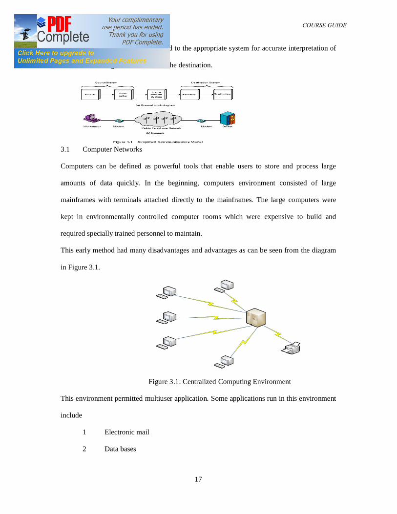
telecommunication system as shown in Figure 1.1 consists of three elements:
DAM 361 COURSE GUIDE
16
(i) A transmitter that takes information and converts it to a signal;
(ii) A transmission medium that carries the signal;
(iii) A receiver that receives the signal and converts it back into usable information.
2.0 Course Objectives:
At the end of this course, students are to
(i) Be able to identify basic communication principles
(ii) Be able to Identify and analyze Computer Networks and Topologies
(iii) To be able to identify the different classifications of computer networks
3.0 Communication Principles
In communication, signals can be either analogue or digital. In an analogue signal, the signal
is varied continuously with respect to the information. In a digital signal, the information is
encoded as a set of discrete values (for example ones and zeros). During transmission the
information contained in analogue signals will be degraded by noise. Conversely, unless the
noise exceeds a certain threshold, the information contained in digital signals will remain
intact. Noise resistance represents a key advantage of digital signals over analogue signals.
From the model diagram in Figure 1.1 the source can be audio or video signal. These signals
on their own can not travel far due to the environmental factors so they are modulated at the
transmitter. The process of modulation transfers the low frequency signal unto a high
frequency carrier frequency. This carrier frequency is selected to overcome the fading effects
of the of the transmission medium (channel) and provide a means of differentiation of the
different transmitted signals at the receiver. At the receiver end the modulation process is
reversed by a process known as demodulation whereby the carrier frequency is separated
DAM 361 COURSE GUIDE
17
from the desired signal and this is fed to the appropriate system for accurate interpretation of
the transmitted signal to the users at the destination.
3.1 Computer Networks
Computers can be defined as powerful tools that enable users to store and process large
amounts of data quickly. In the beginning, computers environment consisted of large
mainframes with terminals attached directly to the mainframes. The large computers were
kept in environmentally controlled computer rooms which were expensive to build and
required specially trained personnel to maintain.
This early method had many disadvantages and advantages as can be seen from the diagram
in Figure 3.1.
Figure 3.1: Centralized Computing Environment
This environment permitted multiuser application. Some applications run in this environment
include
1 Electronic mail
2 Data bases
DAM 361 COURSE GUIDE
18
3 Word processing
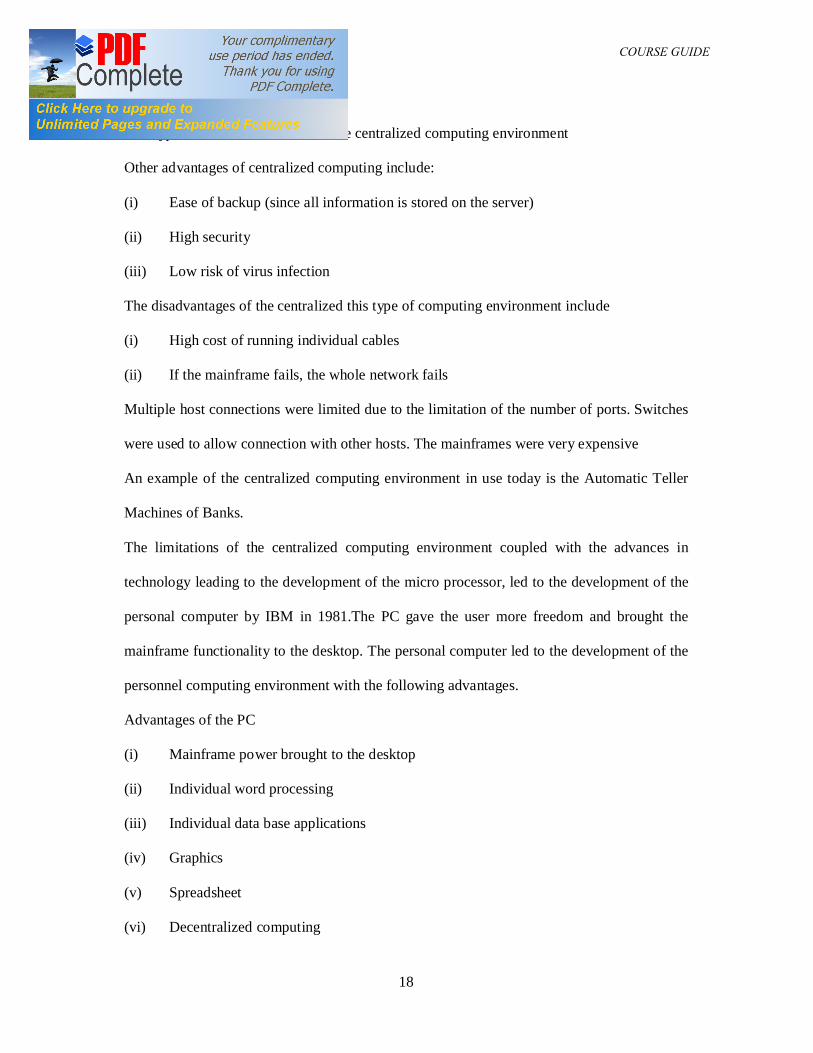
This type of environment is called the centralized computing environment
Other advantages of centralized computing include:
(i) Ease of backup (since all information is stored on the server)
(ii) High security
(iii) Low risk of virus infection
The disadvantages of the centralized this type of computing environment include
(i) High cost of running individual cables
(ii) If the mainframe fails, the whole network fails
Multiple host connections were limited due to the limitation of the number of ports. Switches
were used to allow connection with other hosts. The mainframes were very expensive
An example of the centralized computing environment in use today is the Automatic Teller
Machines of Banks.
The limitations of the centralized computing environment coupled with the advances in
technology leading to the development of the micro processor, led to the development of the
personal computer by IBM in 1981.The PC gave the user more freedom and brought the
mainframe functionality to the desktop. The personal computer led to the development of the
personnel computing environment with the following advantages.
Advantages of the PC
(i) Mainframe power brought to the desktop
(ii) Individual word processing
(iii) Individual data base applications
(iv) Graphics
(v) Spreadsheet
(vi) Decentralized computing
DAM 361 COURSE GUIDE
19
Personal application software running on the PCs were developed
The PC also had the following disadvantages
(i) No electronic mail
(ii) No multiuser capabilities
(iii) Multiple modem and printers
(iv) Very expensive
The disadvantages of the PC were eliminated by the development of Networking
3.2 Introduction to Networking
A Network can be defined as a collection of transmitters, receivers and transceivers that
communicate with each other. Digital networks consist of one or more routers that work
together to transmit information to the correct user. An analogue network consists of one or
more switches that establish a connection between two or more users. For both types of
network, repeaters may be necessary to amplify or recreate the signal when it is being
transmitted over long distances. This is to counter the effect of fading due to the distance
between transmitter and receiver as this fading can render the signal indistinguishable from
the surrounding noise/
Networking can also be defined as a process of connecting computers together either by cable
or other media so that they can share information and resources such as
Printers
Fax devices
Electronic messages
Files and/or documents
Modems
Data
Messages
DAM 361 COURSE GUIDE
20
Networking can also be classified based types listed below
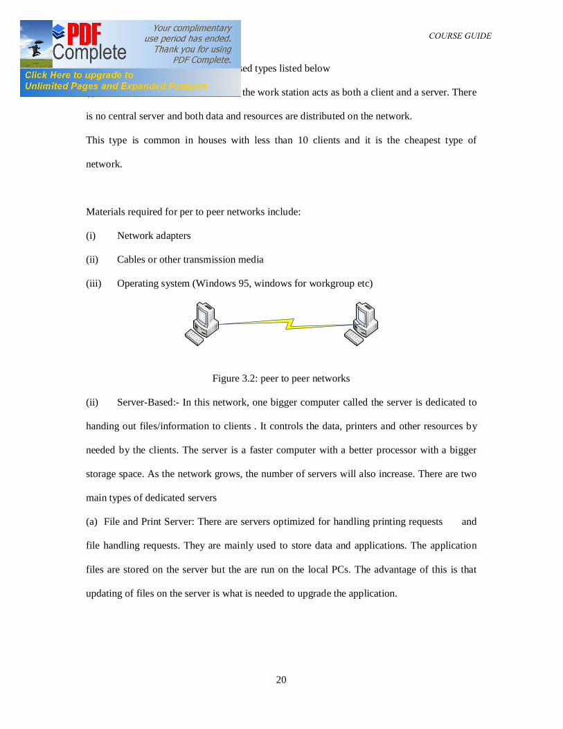
(i) Peer to Peer:- In this method, the work station acts as both a client and a server. There
is no central server and both data and resources are distributed on the network.
This type is common in houses with less than 10 clients and it is the cheapest type of
network.
Materials required for per to peer networks include:
(i) Network adapters
(ii) Cables or other transmission media
(iii) Operating system (Windows 95, windows for workgroup etc)
Figure 3.2: peer to peer networks
(ii) Server-Based:- In this network, one bigger computer called the server is dedicated to
handing out files/information to clients . It controls the data, printers and other resources by
needed by the clients. The server is a faster computer with a better processor with a bigger
storage space. As the network grows, the number of servers will also increase. There are two
main types of dedicated servers
(a) File and Print Server: There are servers optimized for handling printing requests and
file handling requests. They are mainly used to store data and applications. The application
files are stored on the server but the are run on the local PCs. The advantage of this is that
updating of files on the server is what is needed to upgrade the application.
DAM 361 COURSE GUIDE
21
(b) Application server: In application server, arrangement, the application run by the client is
stored on the client. Requests are then sent to the server to be processed. Everything in this
case is done by the server.
Specialized Serves
Some other servers exist with single specialized functions examples are:
Mail server, Communication servers etc.
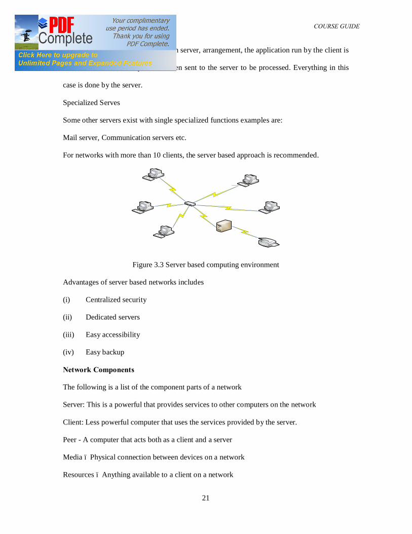
For networks with more than 10 clients, the server based approach is recommended.
Figure 3.3 Server based computing environment
Advantages of server based networks includes
(i) Centralized security
(ii) Dedicated servers
(iii) Easy accessibility
(iv) Easy backup
Network Components
The following is a list of the component parts of a network
Server: This is a powerful that provides services to other computers on the network
Client: Less powerful computer that uses the services provided by the server.
Peer - A computer that acts both as a client and a server
Media – Physical connection between devices on a network
Resources – Anything available to a client on a network
DAM 361 COURSE GUIDE
22
User – Any person that uses a client to access resources on a network
Protocol – Written rules for communications between computer on a network.
3.3 Classification of Networks
Networks can also be classified according to size leading to the following configurations
LOCAL AREA NETWORK (LAN)
The local area network (LAN) is the smallest network size and it is normally contained in a
building. Some characteristics of LANs include
High speed
Smaller error counts
Inexpensive price
METROPOLITAN AREA NETWORKS (MAN)
This is a group of LANs location in a city. MANs are slower than LANs and since they
require special equipment to connect the LANs together and they are costlier. A Metropolitan
Area Network (MAN) is a large computer network that spans a metropolitan area or campus.
Its geographic scope falls between a WAN and LAN. MANs provide Internet connectivity for
LANs in a metropolitan region, and connect them to wider area networks like the Internet.
Some technologies used for this purpose are the ATM and the FDDI. MAN links between
LANs have been built without cables using either microwave radio or infra-red laser links.
Most companies rent or lease circuits from common carriers due to the fact that laying long
stretches of cable can be expensive. Distributed Queue Dual Bus (DQDB), is the
Metropolitan Area Network standard for data communication. Using DQDB, networks can be
up to 30 km long and operate at speeds of 34 to 155 Mbit/s.
WIDE AREA NETWORKS (WAN)
Wide Area Network (WAN) is a computer network that covers a broad area with links across
metropolitan, regional, or national boundaries. The largest and most well-known example of
DAM 361 COURSE GUIDE
23
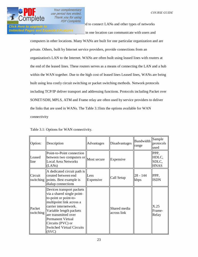
a WAN is the Internet. WANs are used to connect LANs and other types of networks
together, so that users and computers in one location can communicate with users and
computers in other locations. Many WANs are built for one particular organization and are
private. Others, built by Internet service providers, provide connections from an
organization's LAN to the Internet. WANs are often built using leased lines with routers at
the end of the leased lines. These routers serves as a means of connecting the LAN and a hub
within the WAN together. Due to the high cost of leased lines Leased lines, WANs are being
built using less costly circuit switching or packet switching methods. Network protocols
including TCP/IP deliver transport and addressing functions. Protocols including Packet over
SONET/SDH, MPLS, ATM and Frame relay are often used by service providers to deliver
the links that are used in WANs. The Table 3.1lists the options available for WAN
connectivity
Table 3.1: Options for WAN connectivity.
Option: Description Advantages Disadvantages Bandwidth range
Sample protocols used
Leased line
Point-to-Point connection between two computers or Local Area Networks (LANs)
Most secure Expensive
PPP, HDLC, SDLC, HNAS
Circuit switching
A dedicated circuit path is created between end points. Best example is dialup connections
Less Expensive Call Setup 28 - 144
kbps PPP, ISDN
Packet switching
Devices transport packets via a shared single point-to-point or point-to-multipoint link across a carrier internetwork. Variable length packets are transmitted over Permanent Virtual Circuits (PVC) or Switched Virtual Circuits (SVC)
Shared media across link
X.25 Frame-Relay
DAM 361 COURSE GUIDE
24
Cell relay
Similar to packet switching, but uses fixed length cells instead of variable length packets. Data is divided into fixed-length cells and then transported across virtual circuits
Best for simultaneous use of voice and data
Overhead can be considerable ATM
Transmission rate usually range from 1200 bps to 6 Mbps, although some connections such
as ATM and Leased lines can reach speeds greater than 156 Mbps. Typical communication
links used in WANs are telephone lines, microwave links & satellite channels.
3.4 Network Topologies
LAN Topologies
The way the devices on the networks are physically connected is known as the topology. It
includes transmission media, adaptors and the physical design of the network. There are four
main topologies in use.
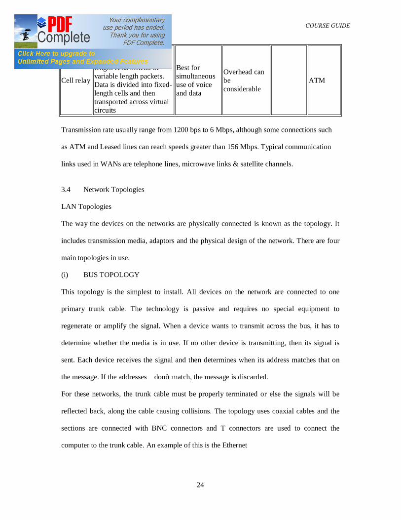
(i) BUS TOPOLOGY
This topology is the simplest to install. All devices on the network are connected to one
primary trunk cable. The technology is passive and requires no special equipment to
regenerate or amplify the signal. When a device wants to transmit across the bus, it has to
determine whether the media is in use. If no other device is transmitting, then its signal is
sent. Each device receives the signal and then determines when its address matches that on
the message. If the addresses don’t match, the message is discarded.
For these networks, the trunk cable must be properly terminated or else the signals will be
reflected back, along the cable causing collisions. The topology uses coaxial cables and the
sections are connected with BNC connectors and T connectors are used to connect the
computer to the trunk cable. An example of this is the Ethernet
DAM 361 COURSE GUIDE
25
Bus topologies are easy to install and configure, inexpensive and easily extended. Both ends,
this coaxial cables are terminated by a 50 ohm resistor. The topology is usually unstable and
connectors used to extend the cable weakens the signals. A break anywhere on the cable
brings down the entire network.
Figure 3.4 Bus topology
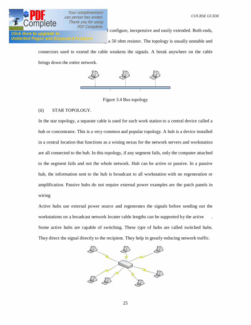
(ii) STAR TOPOLOGY.
In the star topology, a separate cable is used for each work station to a central device called a
hub or concentrator. This is a very common and popular topology. A hub is a device installed
in a central location that functions as a wining nexus for the network servers and workstation
are all connected to the hub. In this topology, if any segment fails, only the computer attached
to the segment fails and not the whole network. Hub can be active or passive. In a passive
hub, the information sent to the hub is broadcast to all workstation with no regeneration or
amplification. Passive hubs do not require external power examples are the patch panels in
wiring
Active hubs use external power source and regenerates the signals before sending out the
workstations on a broadcast network locater cable lengths can be supported by the active .
Some active hubs are capable of switching. These type of hubs are called switched hubs.
They direct the signal directly to the recipient. They help in greatly reducing network traffic.
DAM 361 COURSE GUIDE
26
Figure 3.5: Star Topology
Star topology can be easily expanded as multiple cable types can be supported by the hubs.
Disadvantages include requirement of more cable than other topologies.
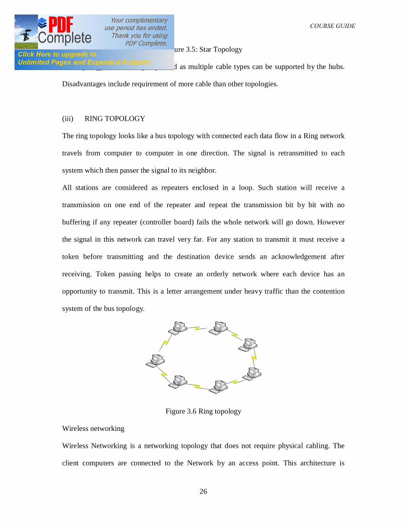
(iii) RING TOPOLOGY
The ring topology looks like a bus topology with connected each data flow in a Ring network
travels from computer to computer in one direction. The signal is retransmitted to each
system which then passer the signal to its neighbor.
All stations are considered as repeaters enclosed in a loop. Such station will receive a
transmission on one end of the repeater and repeat the transmission bit by bit with no
buffering if any repeater (controller board) fails the whole network will go down. However
the signal in this network can travel very far. For any station to transmit it must receive a
token before transmitting and the destination device sends an acknowledgement after
receiving. Token passing helps to create an orderly network where each device has an
opportunity to transmit. This is a letter arrangement under heavy traffic than the contention
system of the bus topology.
Figure 3.6 Ring topology
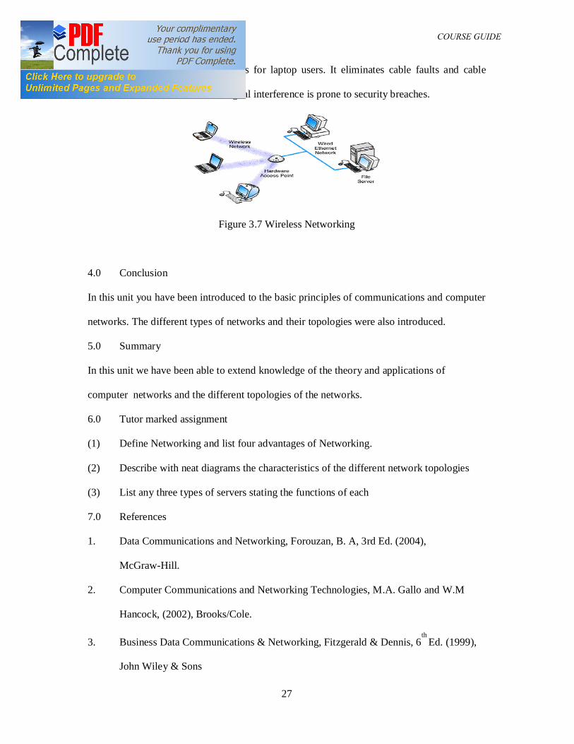
Wireless networking
Wireless Networking is a networking topology that does not require physical cabling. The
client computers are connected to the Network by an access point. This architecture is
DAM 361 COURSE GUIDE
27
particularly useful for remote access for laptop users. It eliminates cable faults and cable
breaks , however it suffers from signal interference is prone to security breaches.
Figure 3.7 Wireless Networking
4.0 Conclusion
In this unit you have been introduced to the basic principles of communications and computer
networks. The different types of networks and their topologies were also introduced.
5.0 Summary
In this unit we have been able to extend knowledge of the theory and applications of
computer networks and the different topologies of the networks.
6.0 Tutor marked assignment
(1) Define Networking and list four advantages of Networking.
(2) Describe with neat diagrams the characteristics of the different network topologies
(3) List any three types of servers stating the functions of each
7.0 References
1. Data Communications and Networking, Forouzan, B. A, 3rd Ed. (2004),
McGraw-Hill.
2. Computer Communications and Networking Technologies, M.A. Gallo and W.M
Hancock, (2002), Brooks/Cole.
3. Business Data Communications & Networking, Fitzgerald & Dennis, 6th
Ed. (1999),
John Wiley & Sons
DAM 361 COURSE GUIDE
28
4. Data and Computer Communications, Stallings W, 5th
Ed. (1997), Prentice Hall, NJ,
5. Business Data Communications and Networking, Fitzgerald and Dennis, ,John
Wiley and Sons, 7th Edition, 2002
6. Networking Series (Parts 1-6), Chappell David, Videos from Chappell and
Associates
7. Halsal, Fred, Data Communications, Computer Networks and Open Systems, Fourth
Edition, Addison-Wesley Publishing Co. (1996).
DAM 361 COURSE GUIDE
29
UNIT TWO TRANSMISSION MEDIA
Table of contents
1.0 Introduction
2.0 Course objectives
3.0 LAN Transmission media
3.1 Thick coaxial cable
3.2 Thin coaxial cable
3.3 Unshielded Twisted Pair
3.4 Optic Fibre
3.5 PBX based LANs
3.6 Ethernet
3.7 ISDN
4.0 Conclusions
5.0 Summary
6.0 Tutor Marked Assignment
7.0 References
1.0 Introduction
There are three major classes of cables used in communication systems. These cables are
(i) Coaxial Cables
(ii) Twisted Pair
(iii) Optic fiber.
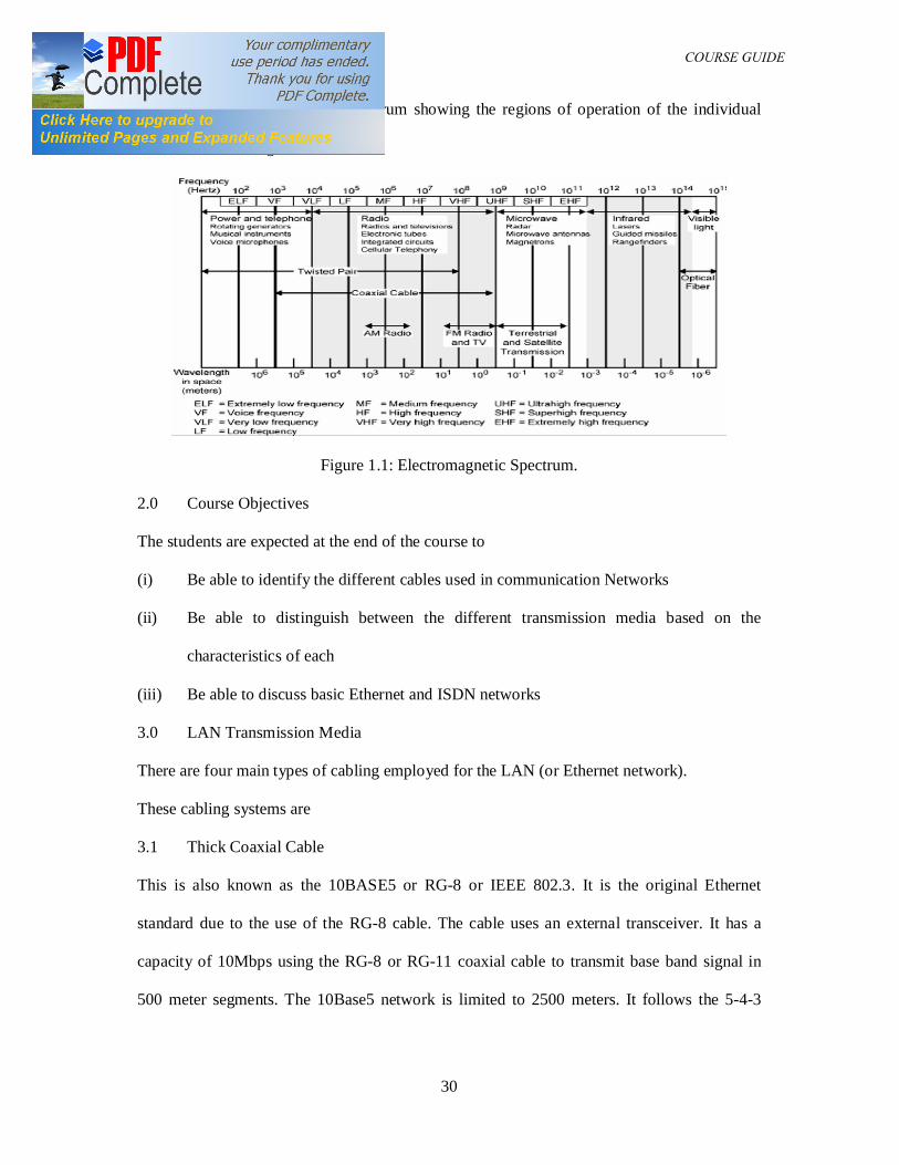
The cables have specific characteristics and the utilization of any type is determined by the
amount of attenuation the present to the signal at the frequency of operation and required
DAM 361 COURSE GUIDE
30
distance. The electromagnetic spectrum showing the regions of operation of the individual
cable is shown in figure 1.1
Figure 1.1: Electromagnetic Spectrum.
2.0 Course Objectives
The students are expected at the end of the course to
(i) Be able to identify the different cables used in communication Networks
(ii) Be able to distinguish between the different transmission media based on the
characteristics of each
(iii) Be able to discuss basic Ethernet and ISDN networks
3.0 LAN Transmission Media
There are four main types of cabling employed for the LAN (or Ethernet network).
These cabling systems are
3.1 Thick Coaxial Cable
This is also known as the 10BASE5 or RG-8 or IEEE 802.3. It is the original Ethernet
standard due to the use of the RG-8 cable. The cable uses an external transceiver. It has a
capacity of 10Mbps using the RG-8 or RG-11 coaxial cable to transmit base band signal in
500 meter segments. The 10Base5 network is limited to 2500 meters. It follows the 5-4-3
DAM 361 COURSE GUIDE
31
rule. This rule defines the configurations of the Network and it states that the network
comprises of 5 segments with 4 repeaters and only 3 segments can have work stations.
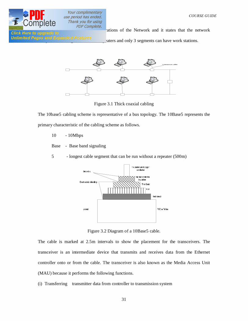
Figure 3.1 Thick coaxial cabling
The 10base5 cabling scheme is representative of a bus topology. The 10Base5 represents the
primary characteristic of the cabling scheme as follows.
10 - 10Mbps
Base - Base band signaling
5 - longest cable segment that can be run without a repeater (500m)
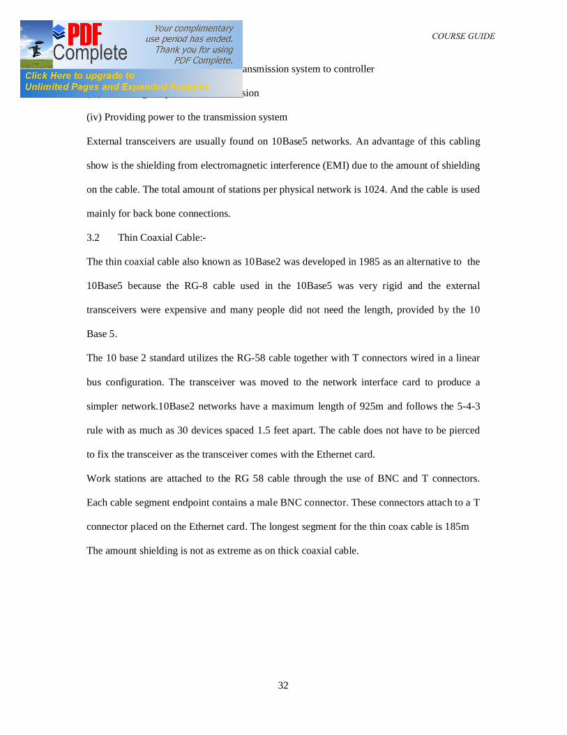
Figure 3.2 Diagram of a 10Base5 cable.
The cable is marked at 2.5m intervals to show the placement for the transceivers. The
transceiver is an intermediate device that transmits and receives data from the Ethernet
controller onto or from the cable. The transceiver is also known as the Media Access Unit
(MAU) because it performs the following functions.
(i) Transferring transmitter data from controller to transmission system
DAM 361 COURSE GUIDE
32
(ii) Transferring receiver data from transmission system to controller
(iii) Indicating the presence of a collision
(iv) Providing power to the transmission system
External transceivers are usually found on 10Base5 networks. An advantage of this cabling
show is the shielding from electromagnetic interference (EMI) due to the amount of shielding
on the cable. The total amount of stations per physical network is 1024. And the cable is used
mainly for back bone connections.
3.2 Thin Coaxial Cable:-
The thin coaxial cable also known as 10Base2 was developed in 1985 as an alternative to the
10Base5 because the RG-8 cable used in the 10Base5 was very rigid and the external
transceivers were expensive and many people did not need the length, provided by the 10
Base 5.
The 10 base 2 standard utilizes the RG-58 cable together with T connectors wired in a linear
bus configuration. The transceiver was moved to the network interface card to produce a
simpler network.10Base2 networks have a maximum length of 925m and follows the 5-4-3
rule with as much as 30 devices spaced 1.5 feet apart. The cable does not have to be pierced
to fix the transceiver as the transceiver comes with the Ethernet card.
Work stations are attached to the RG 58 cable through the use of BNC and T connectors.
Each cable segment endpoint contains a male BNC connector. These connectors attach to a T
connector placed on the Ethernet card. The longest segment for the thin coax cable is 185m
The amount shielding is not as extreme as on thick coaxial cable.
DAM 361 COURSE GUIDE
33
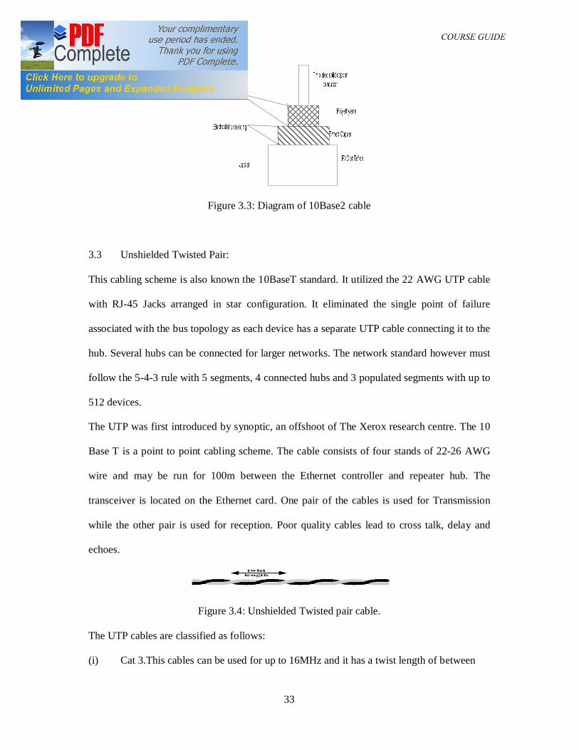
Figure 3.3: Diagram of 10Base2 cable
3.3 Unshielded Twisted Pair:
This cabling scheme is also known the 10BaseT standard. It utilized the 22 AWG UTP cable
with RJ-45 Jacks arranged in star configuration. It eliminated the single point of failure
associated with the bus topology as each device has a separate UTP cable connecting it to the
hub. Several hubs can be connected for larger networks. The network standard however must
follow the 5-4-3 rule with 5 segments, 4 connected hubs and 3 populated segments with up to
512 devices.
The UTP was first introduced by synoptic, an offshoot of The Xerox research centre. The 10
Base T is a point to point cabling scheme. The cable consists of four stands of 22-26 AWG
wire and may be run for 100m between the Ethernet controller and repeater hub. The
transceiver is located on the Ethernet card. One pair of the cables is used for Transmission
while the other pair is used for reception. Poor quality cables lead to cross talk, delay and
echoes.
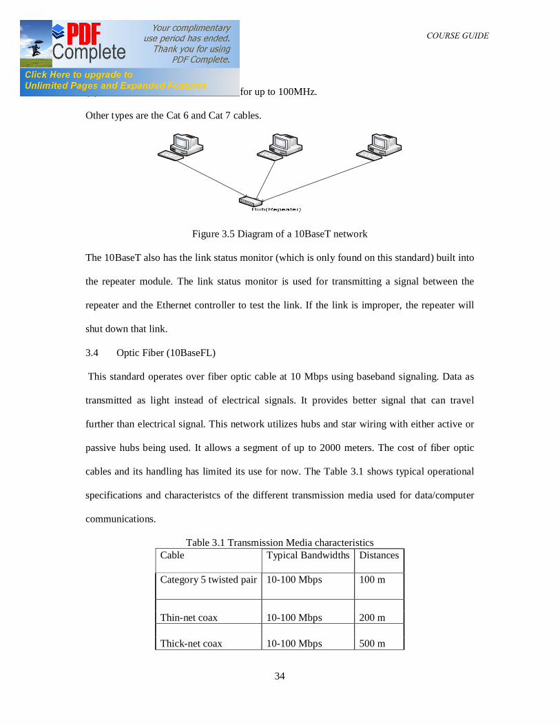
Figure 3.4: Unshielded Twisted pair cable.
The UTP cables are classified as follows:
(i) Cat 3.This cables can be used for up to 16MHz and it has a twist length of between
DAM 361 COURSE GUIDE
34
7.5 cm and 10cm.
(ii) Cat 5 .This cable can be used for up to 100MHz.
Other types are the Cat 6 and Cat 7 cables.
Figure 3.5 Diagram of a 10BaseT network
The 10BaseT also has the link status monitor (which is only found on this standard) built into
the repeater module. The link status monitor is used for transmitting a signal between the
repeater and the Ethernet controller to test the link. If the link is improper, the repeater will
shut down that link.
3.4 Optic Fiber (10BaseFL)
This standard operates over fiber optic cable at 10 Mbps using baseband signaling. Data as
transmitted as light instead of electrical signals. It provides better signal that can travel
further than electrical signal. This network utilizes hubs and star wiring with either active or
passive hubs being used. It allows a segment of up to 2000 meters. The cost of fiber optic
cables and its handling has limited its use for now. The Table 3.1 shows typical operational
specifications and characteristcs of the different transmission media used for data/computer
communications.
Table 3.1 Transmission Media characteristics Cable Typical Bandwidths Distances
Category 5 twisted pair 10-100 Mbps 100 m
Thin-net coax 10-100 Mbps 200 m Thick-net coax 10-100 Mbps 500 m
DAM 361 COURSE GUIDE
35
Multi-mode fiber 100 Mbps 2 km
Single-mode fiber 100-2400 Mbps 40 km
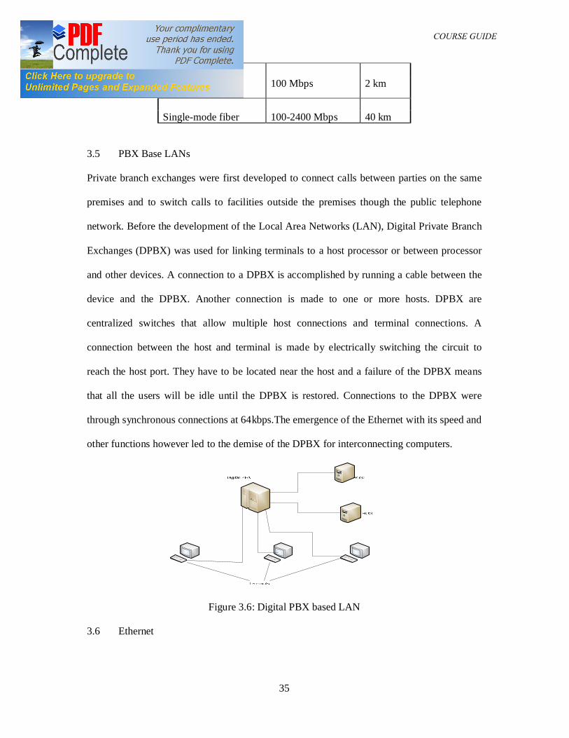
3.5 PBX Base LANs
Private branch exchanges were first developed to connect calls between parties on the same
premises and to switch calls to facilities outside the premises though the public telephone
network. Before the development of the Local Area Networks (LAN), Digital Private Branch
Exchanges (DPBX) was used for linking terminals to a host processor or between processor
and other devices. A connection to a DPBX is accomplished by running a cable between the
device and the DPBX. Another connection is made to one or more hosts. DPBX are
centralized switches that allow multiple host connections and terminal connections. A
connection between the host and terminal is made by electrically switching the circuit to
reach the host port. They have to be located near the host and a failure of the DPBX means
that all the users will be idle until the DPBX is restored. Connections to the DPBX were
through synchronous connections at 64kbps.The emergence of the Ethernet with its speed and
other functions however led to the demise of the DPBX for interconnecting computers.
Figure 3.6: Digital PBX based LAN
3.6 Ethernet
DAM 361 COURSE GUIDE
36
It is the most popular LAN technology in use and was invented by Bob Metcalfe of Xerox in
1973. It is an asynchronous technology. There are no time slots and no central control of
accessing the transmission medium.
Ethernet utilizes the following schemes for media access.
(i) Carrier sensing by each station to make sure no one is using the transmission line before it
transmit.
(ii) Collision detention: Studying the signal or the transmission line to determine if another
station has tried to transmit when it was transmitting.
These two techniques as regarded as CSMA/CD (Carrier Sense Multiple Access with
Collision Detection)
(iii) Random Back Off:- When a collision is detected the systems all became silent and each
systems with a packet to send selects a random delay before attempting to resend. If the
collision reoccurs, the process is repeated but with larger time delay. This leads to low data
rates on Ethernet network.
3.7 ISDN
ISDN is an acronym for Integrated Services Digital Network. Its is a telecommunications
network which supports a wide range of services such as voice, fax, data, video etc with a
digital end-to-end connectivity using a limited set of connection types and interface
arrangements. The ISDN has two standard types of user-network interfaces. These are :
(a) Basic Rate Access (BRA)
BRA provides digital line connection of desktop terminal equipment to the ISDN. The BRA
interface consists of two bearer channels (B-channels) and one data channel (D-channel).
Each B-channel transmits user information with a capacity of 64 kilo bits per second (kbit/s),
while the D-channel carries call set-up and signaling information at 16 kbit/s. The BRA
DAM 361 COURSE GUIDE
37
interface is also referred to as a 2B+D connection which provides a total traffic carrying
capacity of 144 kbit/s.
(b) Primary Rate Access (PRA)
PRA provides a high speed digital trunk connection of medium/large terminal equipment to
the ISDN. There are two options of PRA according to the different transmission standards
employed:
(i) 23B+D connection consists of twenty-three Bchannels each at 64 kbit/s plus one D-
channel at 64 kbit/s,with the total traffic carrying capacity thus at 1544 kbit/s
(ii) 30B+D connection which consists of thirty B-channels each at 64 kbit/s plus one D-
channel at 64 kbit/s, with the total capacity thus at 2048 kbit/s
4.0 Conclusion
In this unit you have been introduced to the different types of transmission media utilized in
the development and setting up of computer networks. The characteristics of these media and
their areas of application have also been discussed.
5.0 Summary
In this unit we have been able to extend knowledge of the theory and applications of
computer networks by treating the different transmission media utilized in setting up the
different networks.
6.0 Tutor marked assignment
(1) Describe with appropriate diagrams the different types of the cables utilized in the
development of computer networks
(2) Write short notes on the suitability or otherwise of the use of any of the cables for the
implementation of a backbone connection.
7.0 References
DAM 361 COURSE GUIDE
38
1. Data Communications and Networking, Forouzan, B. A, 3rd Ed. (2004),
McGraw-Hill.
2. Computer Communications and Networking Technologies, M.A. Gallo and W.M
Hancock, (2002), Brooks/Cole.
3. Business Data Communications & Networking, Fitzgerald & Dennis, 6th
Ed. (1999),
John Wiley & Sons
4. Data and Computer Communications, Stallings W, 5th
Ed. (1997), Prentice Hall, NJ,
5. Business Data Communications and Networking, Fitzgerald and Dennis, ,John
Wiley and Sons, 7th Edition, 2002
UNIT THREE: NETWORK PROTOCOLS
Table of contents
1.0 Introduction
2.0 Course objectives
3.0 Network protocols
3.1 OSI layer
3.2 Physical layer
3.3 Datalink layer
3.4 Network layer
3.5 Transport layer
3.6 Session layer
3.7 Presentation layer
3.8 Application layer
3.9 Sample connection
DAM 361 COURSE GUIDE
39
4.0 Conclusions
5.0 Summary
6.0 Tutor Marked Assignment
7.0 References
1.0 Introduction
For computers to be able to communicate, a language must be defined among them that they
understand. This language is called a protocol. The term protocol is often used to refer to a
group or suite, of individual protocols that work together. The protocols within a suite are
assigned different tasks, such as data translation, data handling, error checking, and
addressing. The International Standards Organization in an attempt standardize this protocol
developed a non proprietary reference model in 1984 called the Open System
Interconnection (OSI). This model deals with the Interconnections of open systems.
2.0 Course Objectives
The students are expected at the end of the course to
(i) Be able to itemize the advantages of layered protocol.
(ii) Be able to discuss the OSI layer
(iii) Be able to distinguish between the different layers of the OSI layer
(iv) Be able to identify the different protocols associated with the different layers of the
OSI layer.
3.0 Network Protocols
The OSI model divides a local Area Network System into seven processing layers with each
layer performing specific functions as part of the overall task of allowing application
programs on different systems located anywhere in the world to communicate with each other
as if they programs resided on the same system.
DAM 361 COURSE GUIDE
40
The ISO model is based on modularity and is not specific to software or hardware. No codes
or software are written for the implementation of the model. Its ultimate goal in the inter
possibility between communication products from different vendors.
These layers are chosen for the following advantages:
The design problems involved with computer network are broken down to manageable
portions. With this layered approach, if an improved technique becomes available for a layer,
that layer will be upgraded will be changed without affecting the whole system. The layered
functionality of the different protocols in the OSI model is called a protocol stack. Layering
breaks large complex set of concepts and protocols into smaller pieces making it easier to
upgrade with hardware and software and also to troubleshoot.
Advantages of Layered Protocol Specification
(1) They can be easily learned
(2) Standardized interfaces among layers facilitate modular Engineering where different
products can be designed to provide function for some layers e.g. router for layers 1-3
(3) Inter operability: One vendor can write program for some layers and another vendor
writes for other layers and all the programs work together.
(4) Reduces complexity and allows faster product evolution
(5) It allows for the development of hardware and software optimized for specific
functions.
(6) Each layer has a clearly defined set of responsibilities building on the services
provided by the layer below it.
3.1 OSI LAYER
The OSI Layers are listed below:
Application Layer
DAM 361 COURSE GUIDE
41
Presentation Layer
Session Layer
Transport Layer
Network Layer
Data Layer
Physical Layer
Description of The layers
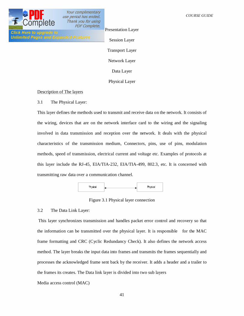
3.1 The Physical Layer:
This layer defines the methods used to transmit and receive data on the network. It consists of
the wiring, devices that are on the network interface card to the wiring and the signaling
involved in data transmission and reception over the network. It deals with the physical
characteristics of the transmission medium, Connectors, pins, use of pins, modulation
methods, speed of transmission, electrical current and voltage etc. Examples of protocols at
this layer include the RJ-45, EIA/TIA-232, EIA/TIA-499, 802.3, etc. It is concerned with
transmitting raw data over a communication channel.
Figure 3.1 Physical layer connection
3.2 The Data Link Layer:
This layer synchronizes transmission and handles packet error control and recovery so that
the information can be transmitted over the physical layer. It is responsible for the MAC
frame formatting and CRC (Cyclic Redundancy Check). It also defines the network access
method. The layer breaks the input data into frames and transmits the frames sequentially and
processes the acknowledged frame sent back by the receiver. It adds a header and a trailer to
the frames its creates. The Data link layer is divided into two sub layers
Media access control (MAC)
DAM 361 COURSE GUIDE
42
Logical link control (LLC)
The Media access control sublayer is responsible for physical addressing and access to the
network media.
The logical link control sublayer is responsible for establishing and maintaining data link
connection between network devices. It performs flow control and error correction in the data
link layer. Examples of protocol for the data link layer include high level data link control
(HDLC), 802.5, frame relay, ATM, FDDI etc.
3.4 The Network Layer:
This layer controls the forwarding of information from one network device to another. It
decides the path data will take if the destination device is located on another network. This
path is through devices called intermediate devices (routers) and it is determined by time and
cost factors. The messages received by the Network layer are converted to packets and the
best route for its transfer to the destination is determined by the Network layer. Connections
between devices at the Network layer are connectionless i.e no connection takes place at this
layer. The best paths for transmission is determined by the process of
(1) Switching
(2) Routing
(3) Addressing
SWITCHING
This describes how data is forwarded across an internetwork. There are three types of
switching techniques and the type utilized is determined by how fast the information needs to
be delivered.
Circuit Switching: In this technique, a dedicated connection is made between the two
communicating devices.
Advantages
DAM 361 COURSE GUIDE
43
(i) No congestion since the link is dedicated for that use
(ii) No channel Access delay: The channel is available in demand
Disadvantages
(i) Inefficient use of the media
(ii) Possible long wait to establish a connection
Message Switching: In this technique, the message is sent from device to device in whole
across the network. This is also known as the store and forward and the information is sent in
whole. This method is not useful for real time applications like voice and video.
Packet Switching: In this technique, the information data is broken into small pieces and
routed from device to device. Devices that forward the data only need to keep the information
in memory and not physical storage.
ROUTING
The network layer utilizes tables set to show the shortest routes between two networks to
route packets across a network. These tables can either be static or dynamic
Static routing tables: These are usually set by the Network Administrator
Dynamic routing :These protocols utilizes the following methods to define the shortest
route.
Distance vector
Link state
ADDRESSING
A device on a network has a network address that tells other computers its location. This
address is used in determine the position of the destination and also is used in determine how
to reach it.
Examples of protocols for the network layer include IP. Apple talk, ICMP etc.
DAM 361 COURSE GUIDE
44
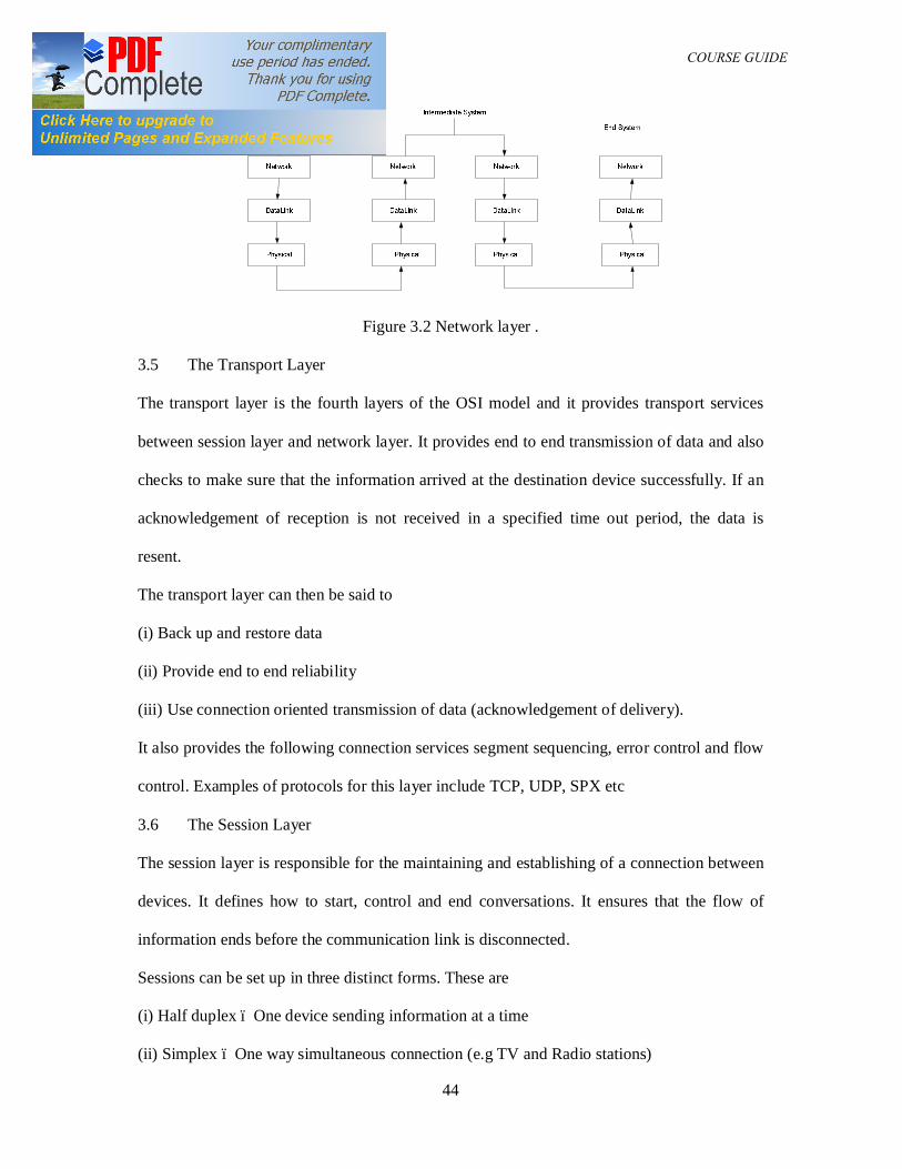
Figure 3.2 Network layer .
3.5 The Transport Layer
The transport layer is the fourth layers of the OSI model and it provides transport services
between session layer and network layer. It provides end to end transmission of data and also
checks to make sure that the information arrived at the destination device successfully. If an
acknowledgement of reception is not received in a specified time out period, the data is
resent.
The transport layer can then be said to
(i) Back up and restore data
(ii) Provide end to end reliability
(iii) Use connection oriented transmission of data (acknowledgement of delivery).
It also provides the following connection services segment sequencing, error control and flow
control. Examples of protocols for this layer include TCP, UDP, SPX etc
3.6 The Session Layer
The session layer is responsible for the maintaining and establishing of a connection between
devices. It defines how to start, control and end conversations. It ensures that the flow of
information ends before the communication link is disconnected.
Sessions can be set up in three distinct forms. These are
(i) Half duplex – One device sending information at a time
(ii) Simplex – One way simultaneous connection (e.g TV and Radio stations)
DAM 361 COURSE GUIDE
45
(iii) Full duplex – Full two way simultaneous connections (e.g Phones)
To establish a session, the user must provide the remote address to which they want to
address. The names are the DNS names e,g, web address, examples of protocols used in the
session layer includes SQL, NFS, NetBios, Apple talk etc
3.7 The Presentation Layer
This layer is responsible for the format in which the data is exchanged. It is responsible for
any set of character or numeric translations e.g. EBCDIC data being translated to ASCII
Binary to BCD etc. Encryption is also implemented in this layer. It is also responsible for
ensuring that the data is sent in the correct order.
Data security compression and character translations are done at the presentation layer since
the data is manipulated character by character at this layer.
EBCDIC – Extended Binary Coded Decimal Interchange Code uses 8 bits to represent up to
256 characters.
ASCII – American Standard Code for Information Interchange uses 7 bits to represent up to
128 bits. The 8th bit is used for parity check.
Examples of protocols used in this layer include, JPEG, MIDI, ASCII, GIF etc
3.8 The Application Layer
This layer is the interface between the users application the network. This enables the users
application to transfer files, send emails and do anything else it needs to do with network. An
example of this protocol is the FTP. It enables the transfer of files across the internet. The
SMTP (Simple Mail Transfer Protocol) provides the ability to distribute electronic mail
across the network.
DAM 361 COURSE GUIDE
46
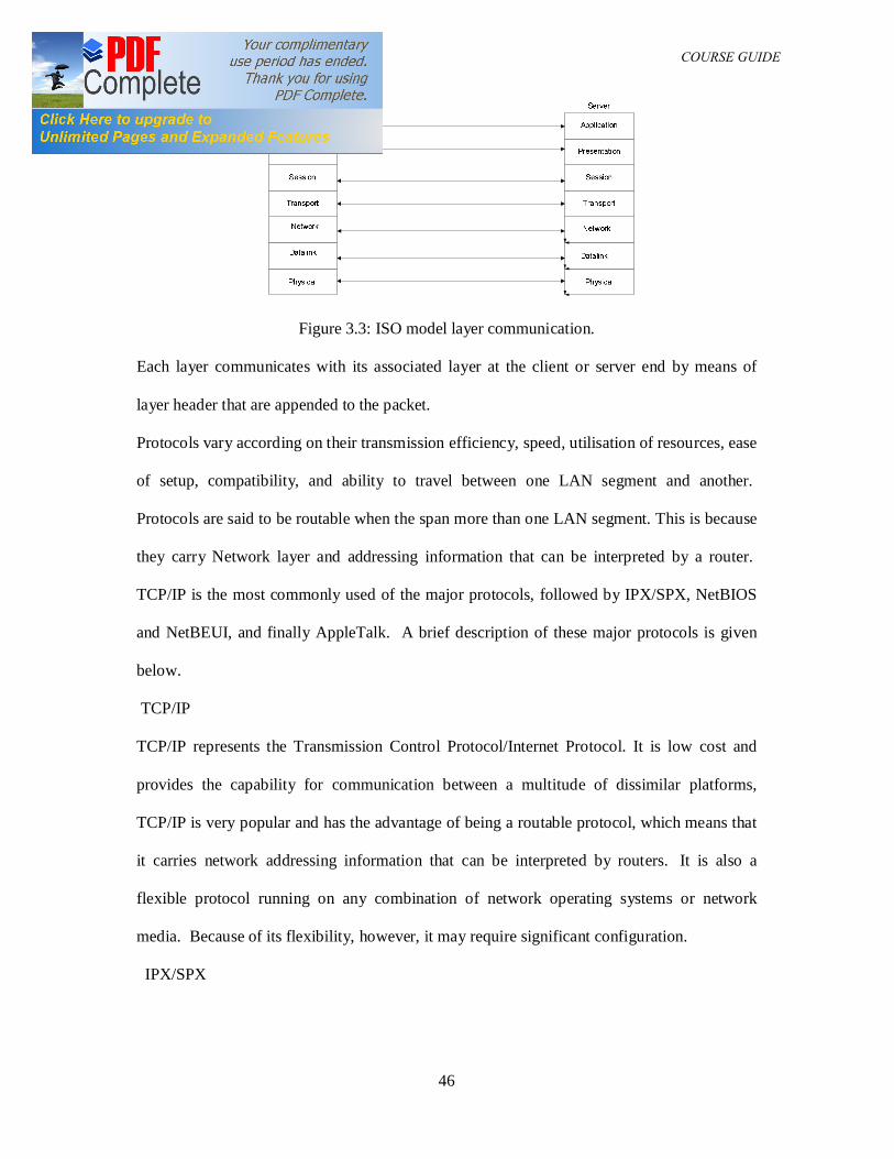
Figure 3.3: ISO model layer communication.
Each layer communicates with its associated layer at the client or server end by means of
layer header that are appended to the packet.
Protocols vary according on their transmission efficiency, speed, utilisation of resources, ease
of setup, compatibility, and ability to travel between one LAN segment and another.
Protocols are said to be routable when the span more than one LAN segment. This is because
they carry Network layer and addressing information that can be interpreted by a router.
TCP/IP is the most commonly used of the major protocols, followed by IPX/SPX, NetBIOS
and NetBEUI, and finally AppleTalk. A brief description of these major protocols is given
below.
TCP/IP
TCP/IP represents the Transmission Control Protocol/Internet Protocol. It is low cost and
provides the capability for communication between a multitude of dissimilar platforms,
TCP/IP is very popular and has the advantage of being a routable protocol, which means that
it carries network addressing information that can be interpreted by routers. It is also a
flexible protocol running on any combination of network operating systems or network
media. Because of its flexibility, however, it may require significant configuration.
IPX/SPX
DAM 361 COURSE GUIDE
47
Internetwork Packet Exchange/Sequenced Packet Exchange is a protocol responsible for the
interoperability of LANs running NetWare operating system. Other network operating
systems, such as Windows NT, and workstation operating systems, such as Windows 95, can
use IPX/SPX to internetwork with Novell NetWare systems.
NetBIOS and NetBEUI
NetBIOS is a protocol originally designed by IBM to provide Transport and Session layer
services for applications running on small, homogenous networks. NetBEUI is a fast and
efficient protocol that consumes few network resources, provides excellent error correction,
and requires little configuration. Furthermore, because NetBEUI lacks a network layer
(addressing information), it is non routable. Thus, this protocol is not suitable for large
networks. Today, NetBEUI is most commonly used in small Microsoft-based networks while
the TCP/IP has become the protocol of choice because it is more flexible and scalable than
NetBEUI.
AppleTalk
AppleTalk is the protocol suite use to interconnect Macintosh computers. Although
AppleTalk was originally designed to support peer-to-peer networking among Macintoshes, it
can now be routed between network segments and integrated with NetWare or Microsoft-
based networks. Although Apple has improved AppleTalk's ability to use different network
models and span network segments, it remains unsuited to large LANs or WANs.
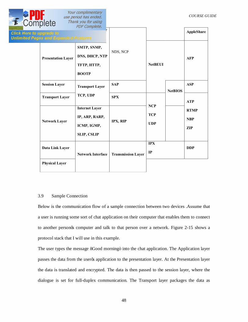
The Table 3.1shows the OSI layers and the possible protocols that operate at the different
layers.
Table 3.1: OSI layers and possible protocols for the different layers OSI MODEL TCP/IP IPX/SPX NetBEUI/NetBIOS AppleTalk
DAM 361 COURSE GUIDE
48
Application Layer Application Layer
Telnet, FTP,
SMTP, SNMP,
DNS, DHCP, NTP
TFTP, HTTP,
BOOTP
NDS, NCP
AppleShare
Presentation Layer NetBEUI
AFP
Session Layer Transport Layer
TCP, UDP
SAP
NetBIOS
ASP
Transport Layer SPX
NCP
TCP
UDP
ATP
RTMP
NBP
ZIP
Network Layer
Internet Layer
IP, ARP, RARP,
ICMP, IGMP,
SLIP, CSLIP
IPX, RIP
Data Link Layer
Network Interface Transmission Layer
IPX
IP DDP
Physical Layer
3.9 Sample Connection
Below is the communication flow of a sample connection between two devices .Assume that
a user is running some sort of chat application on their computer that enables them to connect
to another person’s computer and talk to that person over a network. Figure 2-15 shows a
protocol stack that I will use in this example.
The user types the message “Good morning” into the chat application. The Application layer
passes the data from the user’s application to the presentation layer. At the Presentation layer
the data is translated and encrypted. The data is then passed to the session layer, where the
dialogue is set for full-duplex communication. The Transport layer packages the data as
DAM 361 COURSE GUIDE
49
segments. The recipient’s name is resolved to the corresponding IP address. Checksums are
added for error checking.
Next, the Network layer packages the data diagrams. After examining the IP address, the
destination device is discovered to be on a remote network. The IP address for the
intermediate device is then added as the next destination. Data is sent to the Data Link Layer,
where it is packaged as frames. The physical address of the device is resolved. This is the
address belonging to the intermediate device, which will forward the data on to its
destination. The access type for the network is determined to be Ethernet.
The data is then passed on to the Physical layer, where it is packaged as bits and sent
from the network adapter across the transmission media. The intermediate device reads the
bits off the network media at the Physical layer. The data link layer packages the data as
frames. The physical address of the destination device is resolved to its IP address. The
network layer packages the data as datagrams .After examining the IP address of the
destination device, the location of this device on the network is determined. The data is
passed back to the MAC address. The access type for the network is determined to be
Ethernet.
The data is then sent through the physical layer, packaged as bits, and sent across the network
media. The destination device reads the bits off the network media at the physical layer. The
Data Link layer packages the data as frames. The Physical address of the destination device is
resolved to its IP address. The Network layer packages the data as datagrams. It is determined
that the device has reached its final destination, where it is recorded into the sequence.
4.0 Conclusion
In this unit the layered protocol has been introduced and the OSI layers were discussed with
protocols for each layer itemized.
5.0 Summary
DAM 361 COURSE GUIDE
50
In this unit we have been able to extend knowledge of the theory and applications of
computer networks by treating the layered protocols and the OSI layers.
6.0 Tutor Marked Assignment
(1) List any five advantages of layered protocol
(2) Define the term protocol and list any three protocols
(3) Discuss the OSI layers functions and list one protocol for each layer.
7.0 References
1. Data and Computer Communications, Stallings W, 5th
Ed. (1997), Prentice Hall, NJ,
2. Business Data Communications and Networking, Fitzgerald and Dennis, ,John
Wiley and Sons, 7th Edition, 2002
3. Applied Data Communications: A Business-Oriented Approach, 4th Edition Goldman
James E. & Rawles Phillip T, John Wiley & Sons, 2003
4. Networking Series (Parts 1-6), Chappell David, Videos from Chappell and
Associates
5. Periodical and Technical References of Text book by Goldman
http://www.wiley.com/college/goldman/ref.html
MODULE TWO
UNIT FOUR: IEEE 802 LAN STANDARDS
Table of contents
1.0 Introduction
2.0 Course objectives
3.0 Networking Standards
3.1 IEEE 802 LAN Standards
3.2 IEEE 802.2
3.3 IEEE 802.3
DAM 361 COURSE GUIDE
51
3.4 IEEE 802.4
3.5 IEEE 802.5
4.0 Conclusions
5.0 Summary
6.0 Tutor Marked Assignment
7.0 References
1.0 Introduction
Standards are specifications brought to the public to allow a multi vendor environment.
Standards ensure that products from different suppliers work together harmoniously.
Propriety Standards on the other hands are standards that are not based on any national or
international standard, they are company specific.
2.0 Course Objectives
At the end of this course, students are expected to
(1) Be able to identify the different types of networking standards
(ii) Be able to differentiate between the IEEE standards and other standards
(iii) Be able to differentiate between the different LAN standards.
3.0 Networking Standards
There are four types of networking standard in use today. These are:
(i) Emerging standards
(ii) Industry standards
(iii) Defacto standards
(iv) Committee standards.
All ISO Standards and other international standards come from the international standards
organization (ISO), the Consultative Committee for International Telephone and Telegraph
(CCITT) and the Institute for Electrical and Electronics Engineers (IEEE) The ISO is
DAM 361 COURSE GUIDE
52
headquartered in Geneva Switzerland where it coordinates the efforts of National standard
organization like American National Standard Instituted (ANSI), the Standard Organization
of Nigerian (SON) etc.
The IEEE is closely affiliated with ANSI and has made significant contribution to the
development of LAN standards. The IEEE standards are developed by the 802 committees.
The CCITT is a division of the ITU and it reports to the UN. Its primary assignment is to
recommend standards for International adoption. CCITT recommendations are identified by
the prefix X.IEEE standards are preceded by IEEE and a number e.g. IEEE 802. Another
number can be attached e.g. IEEE 802.3 which specifies a sub group under the working
group. IEEE standards are developed by Technical Committee and standard co-coordinating
committee of the IEEE standards board. The standards are reviewed at least once in 5 years.
3.1 The IEEE 802 LAN Standards
The IEEE 802 standard is a suite of standards defining interfaces and protocols for LANs.
The IEEE 802.X specifications are for the three lowest layers (physical, Data link and
Network of the OSI layers).
This IEEE 802.1 defines the network layer while the remaining 802 specifications relate to
the data link and physical layers. The IEEE divides the data link layer into the logical link
control LLC and the Media Access Control sublayer.
The LLC is responsible for establishing a logical connection between computer on a network
and also it interprets message packets called Protocol Data Unit (PDU) The MAC sub layer
resides between the physical layer and the LLC and provides access to the physical network
port as well as perform message packet framing, deframing and error detection.
3.2 The IEEE 802.2
The 802.2 standard defines the functions of the LLC sub layer. An 802.2 compatible interface
provides services that fall into two major categories.
DAM 361 COURSE GUIDE
53
They are:
(i) Unacknowledged Connectionless Services: This service permits network users
transmit and receive information without establishing a confirmed link between source and
destination.
(ii) Connection Oriented Services: A protocol for establishing, using and terminating
virtual connections between network users
3.3 The IEEE 802.3
This specification defines the CSMA/CD protocol. The Ethernet protocol is based on the
802.3 The CSMA/CD works well for medium networks but as the networks grow in size,
collisions increase and the network slow down. The permissible topologies for the
CSMA/CD are the bus. Star and tree structures to prevent multiple paths between any two
points as in Ring topologies.
3.4 The IEEE 802.4
The 802.4 standard defines the token passing bus access method. Hosts on the network are
connected to a single cable using unidirectional taps like the CSMA/CD. The network
operates like a token passing ring network because the hosts see themselves as being arranged
in a loop with each host knowing the address of stations before and after it.
The token-passing eliminates the collision issues as only one token exist on the network at
any time and only the host with the token is permitted to transmit per time. A token passing
network is superior to the CSMA/CD network for heavy loads.
3.5 The IEEE 802.5
The standard utilizes a token passing techniques as discussed in the 802.4 but the topology in
this case is truly a ring. A host is connected to the network via two cables. One cable for data
reception from its upstream neighbor and the other for transmission to the downstream
neighbor. In the token ring system, one host is used as the active monitor with the
DAM 361 COURSE GUIDE
54
responsibility for detection and correction of ring errors e.g. less of token, incorrectly formed
data packet etc. Other IEEE standards include
IEEE 802.6
IEEE 802.7
IEEE 802.8
IEEE 802.9 etc
The list continues as the standard committees are set up to develop the required standards.
The list below shows the IEEE 802 standards available. The goal of the 802 standards was to
create device standards for different LAN needs.
802.1 - This standard which is now known as the spanning tree algorithm is used to
detect other bridges on the network.
802.2 - This defines the standards for the LLC layer of the data link layer
802.3 - This standard is the CSMA/CD standard which also in the Ethernet standard
802.4 - The 802.4 discussed the Token passing bus which never took off, so it is not
used.
802.5 - This standard is based on IBMs token Ring network standard
802.6 - This network defines standards for MANs, it’s purpose was to define
Distributed Queue Dial Bus (DQDB) a network with two physical channels
802.7 - This standard defines Broadband Technology
802.8 - This standard defines the Filter Optic Technology
802.9 - This standard the Integrated Data and voice network.
802.10- This standard defines Network Security issues
802.11 - This standard is responsible for wireless network.
802.12 - This standard is for the 100mbit data transfer data in next generation
networks. It is called 100VG – AnyLAN.
DAM 361 COURSE GUIDE
55
4.0 Conclusion
In this unit you have been introduced to the different IEEE standards and the development of
these standards and their impact on the LAN.
5.0 Summary
In this unit we have been able to extend knowledge of the theory and applications of
computer networks by treating the different IEEE standards.
6.0 Tutor marked assignment
(1) List any four types of standards
(2) List any three standard developing organizations and discuss any method of
identifying their standards.
(3) Discuss any four IEEE standards
7.0 References
1. Data Communications and Networking, Forouzan, B. A, 3rd Ed. (2004),
McGraw-Hill.
2. Computer Communications and Networking Technologies, M.A. Gallo and W.M
Hancock, (2002), Brooks/Cole.
3. Business Data Communications & Networking, Fitzgerald & Dennis, 6th
Ed. (1999),
John Wiley & Sons
4. Data and Computer Communications, Stallings W, 5th
Ed. (1997), Prentice Hall, NJ,
5. Halsal, Fred, Data Communications, Computer Networks and Open Systems, Fourth
Edition, Addison-Wesley Publishing Co. (1996).
6. Editors of LAN Magazine, LAN Tutorial, Second Edition, Miller Freeman Inc., San
Francisco (1992).
7. Comer, Douglas E., Computer Networks and Internets, Second Edition, Prentice-Hall
International,Inc., N.J. (1999).

DAM 361 COURSE GUIDE
56
8. Computer Networks, 4th Edition by Andrew S. Tanenbaum
9 Business Data Networks and Telecommunications, fourth edition, by Raymond R.
Panko.
10 TCP/IP for Windows2000 by Houde and Hoffman.
UNIT FIVE: MEDIA ACCESS CONTROL
Table of contents
1.0 Introduction
2.0 Course objectives
3.0 Media Access Control
3.1 Addressing
3.2 Contention-based Approach
3.3 Deterministic Approach
4.0 Conclusions
5.0 Summary
DAM 361 COURSE GUIDE
57
6.0 Tutor Marked Assignment
7.0 References
1.0 Introduction
The method of access to the LAN permits all devices attached to the transmission media to
share that medium in a controlled manner. Only one device is permitted to transmit at a time.
If two or more devices attempt to transmit at the same time, they will scramble each others
messages.
2.0 Course Objectives
The student are expected at the end of this course to
(i) Be able to identify media access control methods
(ii) Be able to differentiate between the contention based and deterministic approaches to
media access control
3.0 Media Access Control Methods
There are three ways to control access to the media and these are:
3.1 Addressing:
The data link layer is responsible for the physical address of devices on the network. Every
device on the network has a hard coded address attached to it. This address is also referred to
as the MAC address.
3.2 Contention based Approach:
In a contention based network any device can transmit but at the expense of collisions. To
avoid the collisions, devices listen for other signals on the media before transmitting. The two
most common collision access method are
DAM 361 COURSE GUIDE
58
(a) CSMA/CD (Carrier Sense Multiple Access/Collision Detection)
The CSMA/CD permits any device attached in the medium to transmit when the bus is free
and to monitor for collision during transmission. The transmission sequence on a CSMA/CD
is as follows:
The device listens to the media for any other transmission. This is known as carrier sensing.
If the network media is quiet, the device commences transmission
After transmitting, the device listens to the network to detect any collision.
If collision is detected, the device will send and a signal to all other devices to keep from
sending data for a small period to clear the media.
The transmitting stations will wait a random amount of time before sending their data
If a second collision occur with the same devices, the repeat the above steps with double the
random time out before the transmit again.
Ethernet uses the CSMA/CD method
(b) The second CSMA method is called CSMA/CA (Career Sense Multiple Access/Collision
Avoidance)
The sequence of events in the CSMA/CA approach is as follows:
The device wanting to send checks the media for any active transmissions.
If the media is clear, the device sends a request to send message.
If it is okay to transmit, the network server responds with a clear to send signal.
When the signal is received, the device transmits.
When the transmission is complete, the device sends out an abort sequence to indicate that it
has finished transmission.
3.3 Deterministic Approach
In a deterministic network, a transmitting order has to be established before transmission
takes place. There are two types of deterministic network:
DAM 361 COURSE GUIDE
59
(i) Token passing:- A token is a small data frame pass from device to device across the
network in a predetermined order. The device in possession of the token has control of the
medium for a predetermined maximum time while in possession of the message packet.
A token ring controller may be in any one of the following slate
(a) repeat mode (b) transmit mode (c) copy mode
On receiving the token, the device appends data and destination address to the token, places it
on the network and waits for acknowledgement from the addressed destination host. The
destination host on receiving the data sends a reply to the data source when the device has
finished transmission, the token is passed to the next device in predetermine sequence.
There is currently no speed specification on Token Rings even through IBM support 4Mbps
and 16Mbps as against the 10Mbps of the Ethernet. The networks operate only at one speed,
either 4Mbps or 16Mbps. Two networks operating at difficult speeds may coexist but they
must be separated by devises called BRIDGES.
Advantages of Token Ring include:
(1) Special devices can have higher priorities
(2) It is more efficient under high network load than contention based networks
(3) Network access is predictable
3.4 Polling System:
In this system, a master device checks order secondary devices in the network and their
priorities can be set by the administrator. Its advantages includes the fact that little bandwidth
is lost when the network reaches high utilization.
4.0 Conclusion
DAM 361 COURSE GUIDE
60
In this unit you have been introduced to the different media access control methods used in
the local area networks and the advantages of each.
5.0 Summary
In this unit we have been able to extend knowledge of the theory of computer networks by a
study of the different media access schemes and their characteristics.
6.0 Tutor marked assignment
(1) List any three media access control method, discuss the application of each method
(2) Discuss the disadvantage of Token passing networks
(3) Discuss the CSMA/CD media access scheme
7.0 References
1. Data Communications and Networking, Forouzan, B. A, 3rd Ed. (2004),
McGraw-Hill.
2. Computer Communications and Networking Technologies, M.A. Gallo and W.M
Hancock, (2002), Brooks/Cole.
3. Business Data Communications & Networking, Fitzgerald & Dennis, 6th
Ed. (1999),
John Wiley & Sons
UNIT SIX: INTRODUCTION TO THE INTERNET
Table of contents
1.0 Introduction
2.0 Course objectives
3.0 Transmission Control Protocol
3.1 Internet Protocol
3.2 Functions of IP protocol
3.3 IP Addresses
3.4 Classes of IP Addresses
DAM 361 COURSE GUIDE
61
3.5 Dotted Decimal Notation
3.6 Domain Name System
4.0 Conclusions
5.0 Summary
6.0 Tutor Marked Assignment
7.0 References
1.0 Introduction
A network as defined earlier is a group of communicating devices. The INTERNET is a
collaboration of more than hundreds of thousands of interconnected networks on more than
100 countries. It started in 1969.
Mainframes were used as standalone systems until when the Advanced Research Projects
Agency (ARPA) in Department of Defense (DOD) decided to find a way of connecting
mainframe computers in different locations, so that researchers could share their discoveries,
reducing cost and eliminating duplication of effort.
The ARPANET, a small network of connected computers was presented in 1967 with each
host being connected to a specialized computer called an Interface Messaging Processor (
IMP). The IMP will in turn be connected to one another with the ability of communicating
with one another or their connected hosts.
In 1969, the ARPNetwork was realized with four nodes at
University of California at Los Angeles (UCLA)
University of California at Santa Barbara (UCSB)
Stanford Research Institute (SRI)
University of Utah
DAM 361 COURSE GUIDE
62
The nodes were connected via the IMPs to form a network and a software called Network
Control Protocol (NCP) provided Communication between the hosts,
2.0 Course Objectives
The students are expected to
(i) Be able to discuss the Internet protocols
(ii) Describe the architecture of the internet
(iii) Describe the functions of the IP Protocol
(iv) Discuss the IP classes
(v) Discuss the principles of the domain name system and the dotted decimal notation
3.0 Transmission Control Protocol
In 1973 Vint Lerf and Bob Kahn, members of the ARPANET group presented a paper
outlining the protocols to achieve end to end delivery of packets (Transmission Control
Protocol) (TCP) The TCP was later Split unto two Protocols.
(1) Transmission Control Protocol – (TCP for handling functions like segmentation,
reassembly, error detention.
(2) Internetworking Protocol (IP) – This was to handle datagram routing.
The Internetworking Protocol now became known as the TCP/IP.
The Internet is made up of several wide and local Area Networks joined by connecting
devices and switching stations. Connection to the internet is via Internet Service providers.
There are different levels at which ISPs operate.
International Service providers:- This is the top of the hierarchy and they connect nations
together.
National Service Providers:- There are back bone networks created and maintained by
specialized companies to provide connectivity between end users. The Back bone networks
DAM 361 COURSE GUIDE
63
are connected together by Network Access Point. National Service Providers operate at high
Data rates of up to 600Mbps.
Regional Internet Service Providers:- They are Smaller ISPs. Connected to NSPs. They
operate at a lower date rate.
Local Internet Service Providers:- These are ISPs that provide service to the end users. It
can be a company that provides Internet Services to users e.g. University, Nonprofit
organization. They are usually connected to a regional or national service provider.
3.1 INTERNET PROTOCOLS
Network technologies such as Ethernet, Token Ring, and FDDI provide data link layer
functions by allowing a reliable connection between one node and another on the same
network. For data to be transferred from one network to the other, it requires an addressing
structure which is read by a gateway or a router. The TCP/IP are the pair of protocols used
for internetwork communications. The Internet uses TCP/IP to transfer data where such node
on the internet is assigned a unique network address called an IP address
TCP - Transport layer
IP - Network layer
Ethernet - Data link layer
Data – segments - packets – frames – Bits
Application – Transport - Network – Datalink – Physical
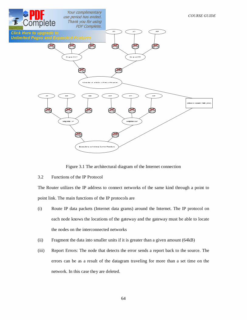
DAM 361 COURSE GUIDE
64
Figure 3.1 The architectural diagram of the Internet connection
3.2 Functions of the IP Protocol
The Router utilizes the IP address to connect networks of the same kind through a point to
point link. The main functions of the IP protocols are
(i) Route IP data packets (Internet data grams) around the Internet. The IP protocol on
each node knows the locations of the gateway and the gateway must be able to locate
the nodes on the interconnected networks
(ii) Fragment the data into smaller units if it is greater than a given amount (64kB)
(iii) Report Errors: The node that detects the error sends a report back to the source. The
errors can be as a result of the datagram traveling for more than a set time on the
network. In this case they are deleted.
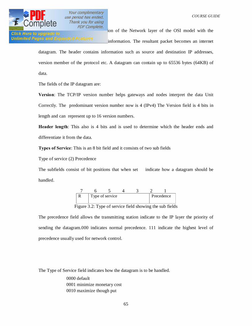
DAM 361 COURSE GUIDE
65
The IP protocol is an implementation of the Network layer of the OSI model with the
addition of a data header onto the information. The resultant packet becomes an internet
datagram. The header contains information such as source and destination IP addresses,
version member of the protocol etc. A datagram can contain up to 65536 bytes (64KB) of
data.
The fields of the IP datagram are:
Version: The TCP/IP version number helps gateways and nodes interpret the data Unit
Correctly. The predominant version number now is 4 (IPv4) The Version field is 4 bits in
length and can represent up to 16 version numbers.
Header length: This also is 4 bits and is used to determine which the header ends and
differentiate it from the data.
Types of Service: This is an 8 bit field and it consists of two sub fields
Type of service (2) Precedence
The subfields consist of bit positions that when set indicate how a datagram should be
handled.
7 6 5 4 3 2 1 R Type of service Precedence
Figure 3.2: Type of service field showing the sub fields
The precedence field allows the transmitting station indicate to the IP layer the priority of
sending the datagram.000 indicates normal precedence. 111 indicate the highest level of
precedence usually used for network control.
The Type of Service field indicates how the datagram is to be handled.
0000 default 0001 minimize monetary cost 0010 maximize though put
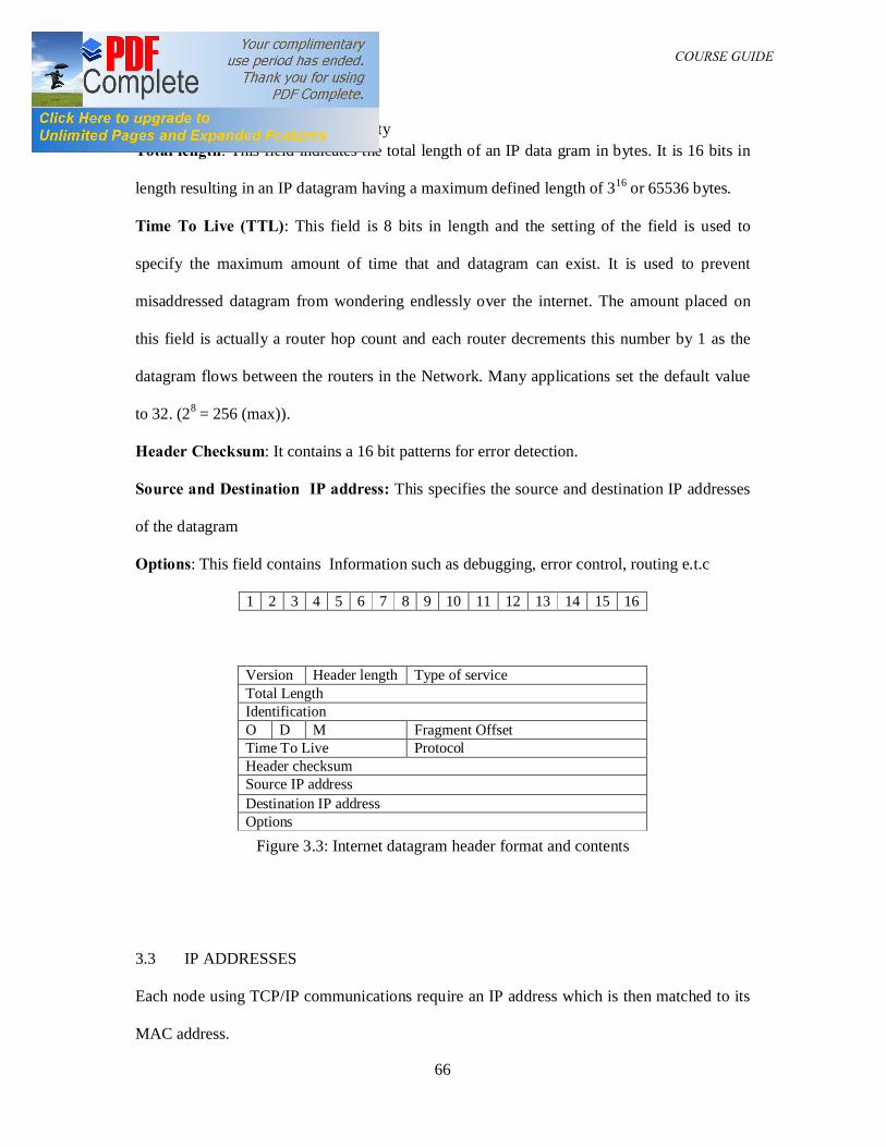
DAM 361 COURSE GUIDE
66
0100 minimize delay 1111 maximize security Total length: This field indicates the total length of an IP data gram in bytes. It is 16 bits in
length resulting in an IP datagram having a maximum defined length of 316 or 65536 bytes.
Time To Live (TTL): This field is 8 bits in length and the setting of the field is used to
specify the maximum amount of time that and datagram can exist. It is used to prevent
misaddressed datagram from wondering endlessly over the internet. The amount placed on
this field is actually a router hop count and each router decrements this number by 1 as the
datagram flows between the routers in the Network. Many applications set the default value
to 32. (28 = 256 (max)).
Header Checksum: It contains a 16 bit patterns for error detection.
Source and Destination IP address: This specifies the source and destination IP addresses
of the datagram
Options: This field contains Information such as debugging, error control, routing e.t.c
1 2 3 4 5 6 7 8 9 10 11 12 13 14 15 16
Figure 3.3: Internet datagram header format and contents
3.3 IP ADDRESSES
Each node using TCP/IP communications require an IP address which is then matched to its
MAC address.
Version Header length Type of service Total Length Identification O D M Fragment Offset Time To Live Protocol Header checksum Source IP address Destination IP address Options
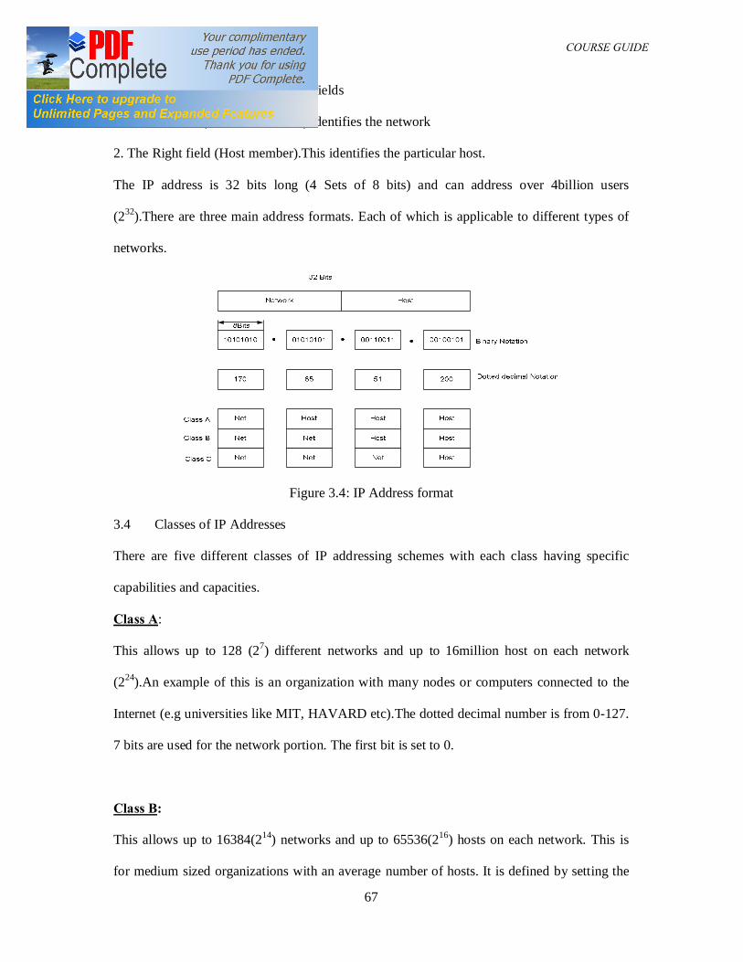
DAM 361 COURSE GUIDE
67
A typical IP address consists of two fields
1. The left field (Network member) identifies the network
2. The Right field (Host member).This identifies the particular host.
The IP address is 32 bits long (4 Sets of 8 bits) and can address over 4billion users
(232).There are three main address formats. Each of which is applicable to different types of
networks.
Figure 3.4: IP Address format
3.4 Classes of IP Addresses
There are five different classes of IP addressing schemes with each class having specific
capabilities and capacities.
Class A:
This allows up to 128 (27) different networks and up to 16million host on each network
(224).An example of this is an organization with many nodes or computers connected to the
Internet (e.g universities like MIT, HAVARD etc).The dotted decimal number is from 0-127.
7 bits are used for the network portion. The first bit is set to 0.
Class B:
This allows up to 16384(214) networks and up to 65536(216) hosts on each network. This is
for medium sized organizations with an average number of hosts. It is defined by setting the
DAM 361 COURSE GUIDE
68
first 2 high order bits of an IP address to 10.The network portion is then represented by the
next 14 bits 214=16384 and the host section 216.(128-191).
Class C:
In this class the first 3 high order bits of the IP address are set to 110 and the network address
is now represented by 221 giving rise to approximately 2 million networks with a total host
per network of 28=256.This class is used by organizations with small networks e .g in
academics institutions, government agencies etc. Since these organizations can have multiple
LANs, multiple class C addresses can also be assigned to them if their hosts are not large
enough to justify a class B address .(192-223)
Class D:
It is defined by assigning 1110 to the first 4 most significant bits of the IP address. The
remaining bits are used to form a multicast address thus there exists 228=268 million possible
multicast addresses. Multicasting is an addressing technique which allows a source to send
information to a selected group via the use of a multicast address.
Class E:
In this class, the first 4 MSB are given the value 1111, thus the remaining 28 bits representing
268.4 million address possibilities. This class is reserved for research purposes.
Note:
All Os in the host part is reserved for the entire network.
e.g 40.0.0.0 (Class A network address)
150.76.0.0 (Class B network address)
199.20.30.0 (Class C network address)
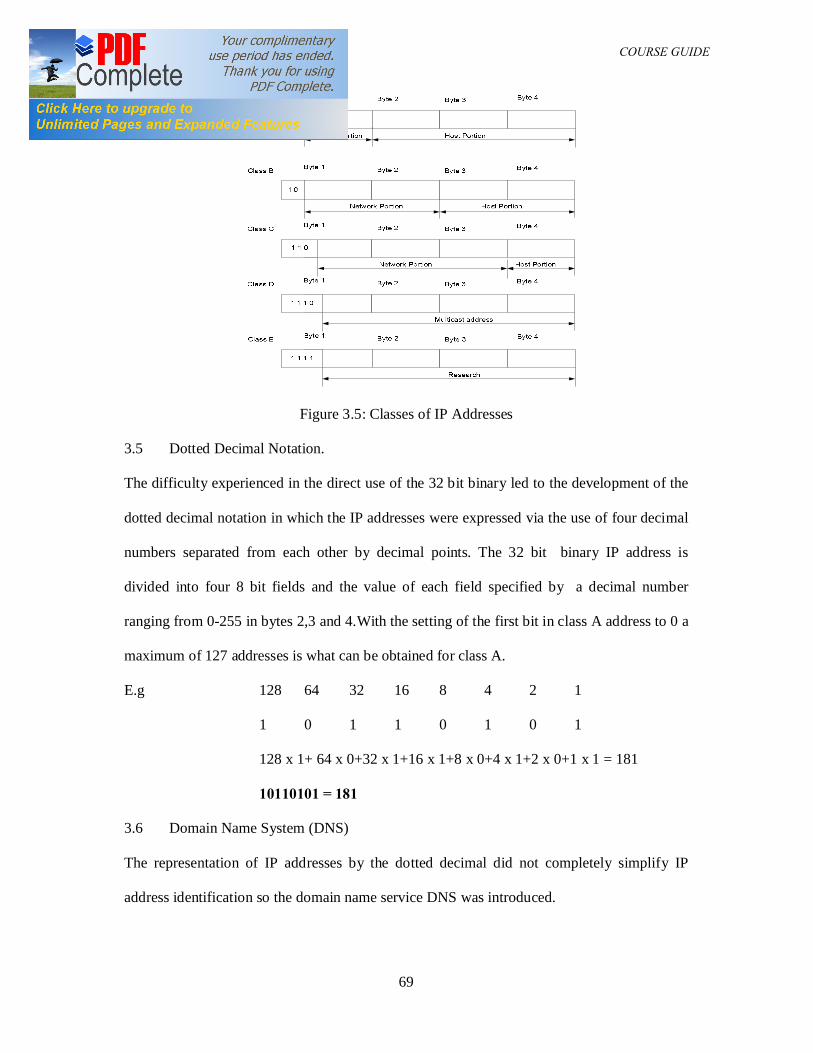
DAM 361 COURSE GUIDE
69
Figure 3.5: Classes of IP Addresses
3.5 Dotted Decimal Notation.
The difficulty experienced in the direct use of the 32 bit binary led to the development of the
dotted decimal notation in which the IP addresses were expressed via the use of four decimal
numbers separated from each other by decimal points. The 32 bit binary IP address is
divided into four 8 bit fields and the value of each field specified by a decimal number
ranging from 0-255 in bytes 2,3 and 4.With the setting of the first bit in class A address to 0 a
maximum of 127 addresses is what can be obtained for class A.
E.g 128 64 32 16 8 4 2 1
1 0 1 1 0 1 0 1
128 x 1+ 64 x 0+32 x 1+16 x 1+8 x 0+4 x 1+2 x 0+1 x 1 = 181
10110101 = 181
3.6 Domain Name System (DNS)
The representation of IP addresses by the dotted decimal did not completely simplify IP
address identification so the domain name service DNS was introduced.
DAM 361 COURSE GUIDE
70
DNS was developed to translate English type names assigned to hosts to their IP address.
DNS computers (name servers) on the internet determine the IP address of the named
destination resource or application program. If the domain name cannot be resolved after
querying other servers, an error message is displayed by the www browser.
Examples of some domain name suffixes are:
Suffix Type of organization
.com commercial organization
.edu educational
.gov Government agency
.mil Military organization
.net Networking organization
.org Non- profit organization
.int International organization
Once an organization has a registered name e.g yahoo.com, it can add a prefix to indicate
specific hosts or applications residing on the host e.g www.yahoo.com meaning that yahoo is
a server for a commercial site (a World Wide Web server).
Each Institution on the internet has a host that runs a process called the domain server. The
DNS maintains a data base called directory information base (DIB) which contains directory
information for that institution. When a new host is added, its name and IP address is added
to the data base.
4.0 Conclusion
In this unit you have been introduced to the internet, the internet protocol and the
classification of IP addresses and the IP addressing schemes.
DAM 361 COURSE GUIDE
71
5.0 Summary
In this unit we have been able to extend knowledge of the theory of computer networks by a
study of the Internet protocols and the process of addressing devices (hosts) on the computer
network.
6.0 Tutor marked assignment
(1) Discuss the principles of the internet connection
(2) Discuss the component parts of the IP header
(3) List the different classes of the IP addresses and the number of hosts each class can
accommodate.
7.0 References
1. Data Communications and Networking, Forouzan, B. A, 3rd Ed. (2004),
McGraw-Hill.
2. Computer Communications and Networking Technologies, M.A. Gallo and W.M
Hancock, (2002), Brooks/Cole.
3. Business Data Communications & Networking, Fitzgerald & Dennis, 6th
Ed. (1999),
John Wiley & Sons
4. Data and Computer Communications, Stallings W, 5th
Ed. (1997), Prentice Hall, NJ,
5. Comer, Douglas E., Computer Networks and Internets, Second Edition, Prentice-Hall
International,Inc., N.J. (1999).
6. Computer Networks, 4th Edition by Andrew S. Tanenbaum
7 Business Data Networks and Telecommunications, fourth edition, by Raymond R.
Panko.
8 TCP/IP for Windows2000 by Houde and Hoffman.
9. Applied Data Communications: A Business-Oriented Approach, 4th Edition Goldman
James E. & Rawles Phillip T, John Wiley & Sons, 2003
DAM 361 COURSE GUIDE
72
MODULE THREE
UNIT SEVEN: SUBNETTING
Table of contents
1.0 Introduction
2.0 Course objectives
3.0 Subnetting
3.1 Advantages of Subnetting
3.2 The Subnet mask
4.0 Conclusions
5.0 Summary
6.0 Tutor Marked Assignment
7.0 References
1.0 Introduction
The two level hierarchical numbering scheme of the IP addresses has a major problem in that
it is inefficient and it leads to the waste of IP addresses .To overcome this waste, the Sub-
netting is a process was developed.
2.0 Course objectives
AT the end of this unit, students are expected to
(i) Discuss the principles of Subnetting
(ii) List the advantages of Subnetting
(iii) Be able to identify the Subnet mask
3.0 Subnetting
Subnetting is a process that involves the division of the two level hierarchy of class A, B and
C networks into a three level hierarchy. The host portion of each 32 bit network address is
used both for the subnet number and the host number.
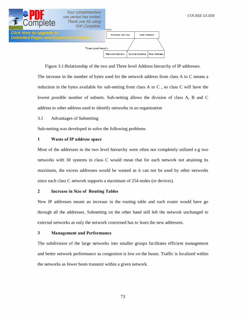
DAM 361 COURSE GUIDE
73
Figure 3.1:Relationship of the two and Three level Address hierarchy of IP addresses.
The increase in the number of bytes used for the network address from class A to C means a
reduction in the bytes available for sub-netting from class A to C , so class C will have the
lowest possible number of subnets. Sub-netting allows the division of class A, B and C
address to other address used to identify networks in an organization
3.1 Advantages of Subnetting
Sub-netting was developed to solve the following problems
1 Waste of IP address space
Most of the addresses in the two level hierarchy were often not completely utilized e.g two
networks with 30 systems in class C would mean that for each network not attaining its
maximum, the excess addresses would be wasted as it can not be used by other networks
since each class C network supports a maximum of 254 nodes (or devices).
2 Increase in Size of Routing Tables
New IP addresses meant an increase in the routing table and each router would have go
through all the addresses. Subnetting on the other hand still left the network unchanged to
external networks as only the network concerned has to learn the new addresses.
3 Management and Performance
The subdivision of the large networks into smaller groups facilitates efficient management
and better network performance as congestion is low on the buses. Traffic is localized within
the networks as fewer hosts transmit within a given network.
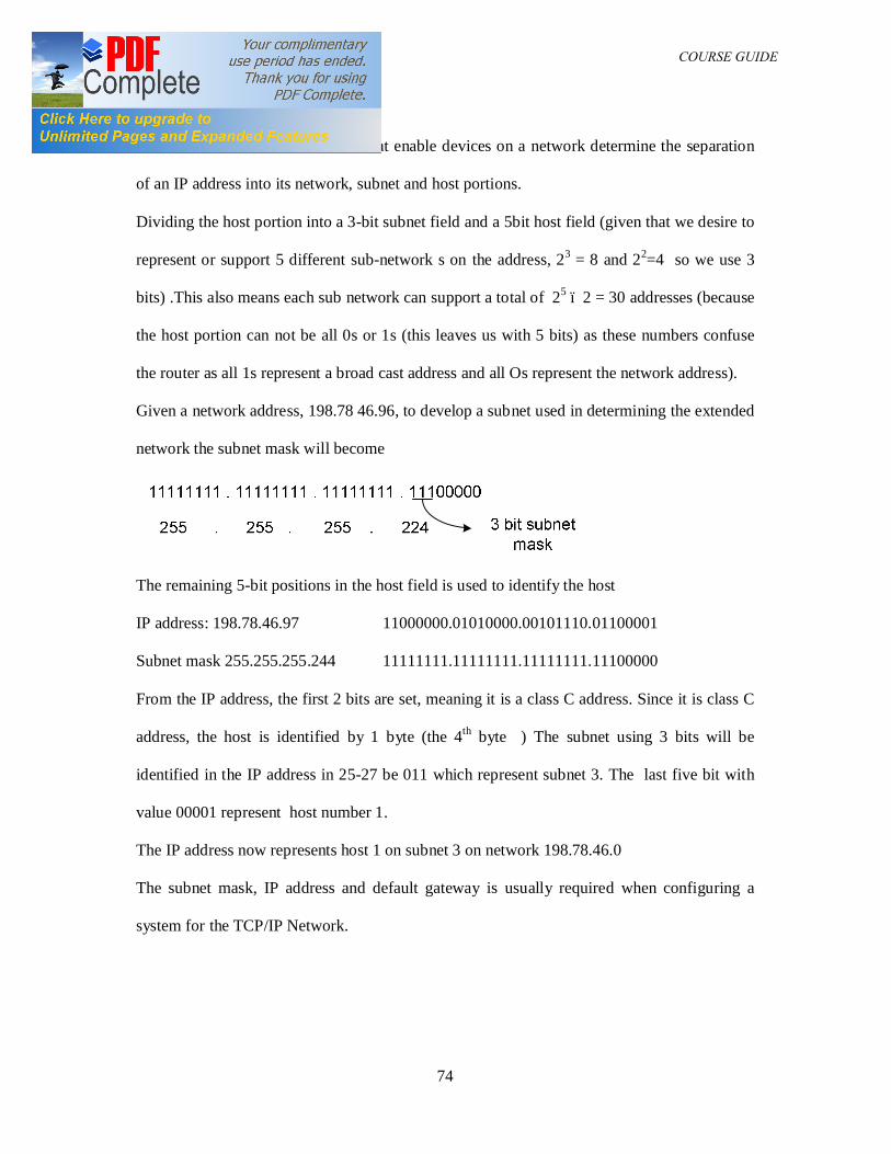
DAM 361 COURSE GUIDE
74
3.2 The Subnet Mask
The subnet mask is a mechanism that enable devices on a network determine the separation
of an IP address into its network, subnet and host portions.
Dividing the host portion into a 3-bit subnet field and a 5bit host field (given that we desire to
represent or support 5 different sub-network s on the address, 23 = 8 and 22=4 so we use 3
bits) .This also means each sub network can support a total of 25 – 2 = 30 addresses (because
the host portion can not be all 0s or 1s (this leaves us with 5 bits) as these numbers confuse
the router as all 1s represent a broad cast address and all Os represent the network address).
Given a network address, 198.78 46.96, to develop a subnet used in determining the extended
network the subnet mask will become
The remaining 5-bit positions in the host field is used to identify the host
IP address: 198.78.46.97 11000000.01010000.00101110.01100001
Subnet mask 255.255.255.244 11111111.11111111.11111111.11100000
From the IP address, the first 2 bits are set, meaning it is a class C address. Since it is class C
address, the host is identified by 1 byte (the 4th byte ) The subnet using 3 bits will be
identified in the IP address in 25-27 be 011 which represent subnet 3. The last five bit with
value 00001 represent host number 1.
The IP address now represents host 1 on subnet 3 on network 198.78.46.0
The subnet mask, IP address and default gateway is usually required when configuring a
system for the TCP/IP Network.
DAM 361 COURSE GUIDE
75
4.0 Conclusion
In this unit you have been introduced to the principles of Subnetting and the advantages of
Subnetting. You have also been introduced to the subnet mask and the process involved in
developing a subnet mask and identifying the capacity of computer networks given the subnet
mask.
5.0 Summary
In this unit we have been able to extend knowledge of the theory of computer networks by a
study of the Subnetting process and the subnet mask and the process of addressing devices
(hosts) on the computer network.
6.0 Tutor marked assignment
(1) Define Subnetting and list any three advantages of Subnetting
(2) Define the subnet mask stating its functions.
7.0 References
1. Data Communications and Networking, Forouzan, B. A, 3rd Ed. (2004),
McGraw-Hill.
2. Computer Communications and Networking Technologies, M.A. Gallo and W.M
Hancock, (2002), Brooks/Cole.
3. Business Data Communications & Networking, Fitzgerald & Dennis, 6th
Ed. (1999),
John Wiley & Sons
4. Periodical and Technical References of Text book by Goldman
http://www.wiley.com/college/goldman/ref.html
5. Comer, Douglas E., Computer Networks and Internets, Second Edition, Prentice-Hall
International,Inc., N.J. (1999).
6. Computer Networks, 4th Edition by Andrew S. Tanenbaum
7 TCP/IP for Windows2000 by Houde and Hoffman.
DAM 361 COURSE GUIDE
76
UNIT EIGHT: INTERNETWORKING
Table of contents
1.0 Introduction
2.0 Course objectives
3.0 Repeaters
3.1 Bridges
3.2 Routers
3.3 Brouters
3.4 Gateway
3.5 Ethernet Hubs
3.6 Switches
3.7 Modems
3.8 Multiplexers
3.9 Packet Switching
4.0 Conclusions
5.0 Summary
6.0 Tutor Marked Assignment
7.0 References
1.0 Introduction
As users on a local network grow, the LAN may reach its limits on distance or number of
modes that can be supported on an individual segment, hardware devices are then needed to
extend the network to form a larger network.
Internetworking and Intranetworking products fall into five different categories namely:
(1) Repeaters
(2) Routers
DAM 361 COURSE GUIDE
77
(3) Gateways
(4) Bridges
(5) Brouters (combination of Bridges and Routers)
Each device function that directly correspond to the ISO layer at which the internet working
function is performed.
2.0 Course Objectives
At the end of this unit students are to
(i) Discuss the place and functionality of the Repeater in a network
(ii) Discuss the place and functionality of the Router in a network
(iii) Discuss the place and functionality of the Gateways in a network
(iv) Discuss the place and functionality of the Bridges in a network
(v) Discuss the place and functionality of the Switches in a network
3.0 REPEATERS
A repeater is a device that operates at the physical layer to regenerate the electrical signal on
the network media. It is used to extend the geographical coverage of a local area network
(LAN) by interconnecting multiple segments. The can also interconnect segments using
different physical media such as thicknet, thinnet and coaxial cables. The repeaters have
very little intelligence and they do not provide any type of traffic isolation. Repeaters also
cannot connect dissimilar networks for example, it cannot connect a CSMA/CD based
network to Token Ring based network
Most networks have a limit to the number of repeaters that can be used to connect segments.
In Ethernet this rule is called the 5-4-3 rule meaning a total of 5 segments connected by 4
repeaters with only 3 segments populated. The repeaters are normally two port boxes. Signal
comes through one port and leaves through the other.
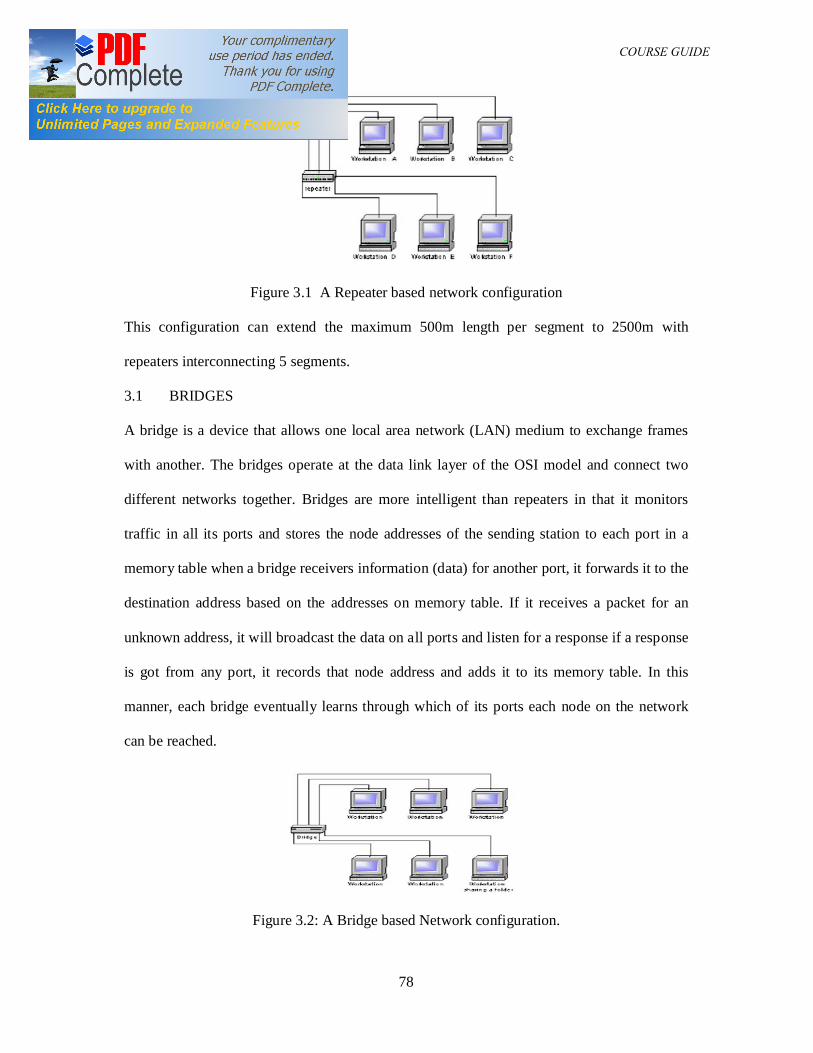
DAM 361 COURSE GUIDE
78
Figure 3.1 A Repeater based network configuration
This configuration can extend the maximum 500m length per segment to 2500m with
repeaters interconnecting 5 segments.
3.1 BRIDGES
A bridge is a device that allows one local area network (LAN) medium to exchange frames
with another. The bridges operate at the data link layer of the OSI model and connect two
different networks together. Bridges are more intelligent than repeaters in that it monitors
traffic in all its ports and stores the node addresses of the sending station to each port in a
memory table when a bridge receivers information (data) for another port, it forwards it to the
destination address based on the addresses on memory table. If it receives a packet for an
unknown address, it will broadcast the data on all ports and listen for a response if a response
is got from any port, it records that node address and adds it to its memory table. In this
manner, each bridge eventually learns through which of its ports each node on the network
can be reached.
Figure 3.2: A Bridge based Network configuration.
DAM 361 COURSE GUIDE
79
Translational bridges are used to connect dissimilar networks. There are two main types of
bridges.
(1) Transparent Bridges
Transparent bridges use hardware network card address to know which data to pass to a
particular node and which to filter out. Computer addresses are stored in a table, one for each
port. When data is received, the destination address is checked and compared against this
table.
(2) Source-route bridges:
The type of bridges are utilized mainly by token ring networks, the information in the token
ring frame is used to determine whether to pass the data or not as against the MAC addresses.
As a standalone device bridges have been made largely obsolete by the introduction of more
advanced switches and routers.
3.2 ROUTERS
Routers are multiport devices that can connect dissimilar networks running at different
transmission speeds and using different protocols. Routers work in the Network layer of the
O.S.I. Model, which allows them to redirect data from one network segment to another.
Routers also have the ability to choose the most effective path for data transmission across a
network, which combined with their ability to connect dissimilar network types, makes them
very powerful. They make intelligent decisions on the path for the data using either the MAC
address or administratively assigned logical address (e.g. IP addresses). This allows the
segmentation of the network into subnets (a subnet is a network connected to another network
in a router).
There are two types of routing
Static – In the static routing, the paths are configured by the system administrator
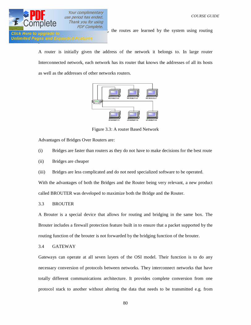
DAM 361 COURSE GUIDE
80
Dynamic – In the dynamic routing, the routes are learned by the system using routing
protocols.
A router is initially given the address of the network it belongs to. In large router
Interconnected network, each network has its router that knows the addresses of all its hosts
as well as the addresses of other networks routers.
Figure 3.3: A router Based Network
Advantages of Bridges Over Routers are:
(i) Bridges are faster than routers as they do not have to make decisions for the best route
(ii) Bridges are cheaper
(iii) Bridges are less complicated and do not need specialized software to be operated.
With the advantages of both the Bridges and the Router being very relevant, a new product
called BROUTER was developed to maximize both the Bridge and the Router.
3.3 BROUTER
A Brouter is a special device that allows for routing and bridging in the same box. The
Brouter includes a firewall protection feature built in to ensure that a packet supported by the
routing function of the brouter is not forwarded by the bridging function of the brouter.
3.4 GATEWAY
Gateways can operate at all seven layers of the OSI model. Their function is to do any
necessary conversion of protocols between networks. They interconnect networks that have
totally different communications architecture. It provides complete conversion from one
protocol stack to another without altering the data that needs to be transmitted e.g. from
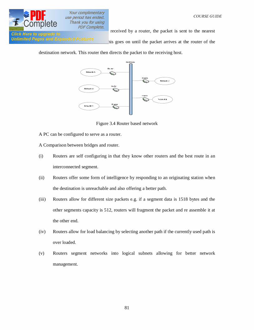
DAM 361 COURSE GUIDE
81
TCP/IP to X.25. Once a packet is received by a router, the packet is sent to the nearest
router to the destination network. This goes on until the packet arrives at the router of the
destination network. This router then directs the packet to the receiving host.
Figure 3.4 Router based network
A PC can be configured to serve as a router.
A Comparison between bridges and router.
(i) Routers are self configuring in that they know other routers and the best route in an
interconnected segment.
(ii) Routers offer some form of intelligence by responding to an originating station when
the destination is unreachable and also offering a better path.
(iii) Routers allow for different size packets e.g. if a segment data is 1518 bytes and the
other segments capacity is 512, routers will fragment the packet and re assemble it at
the other end.
(iv) Routers allow for load balancing by selecting another path if the currently used path is
over loaded.
(v) Routers segment networks into logical subnets allowing for better network
management.
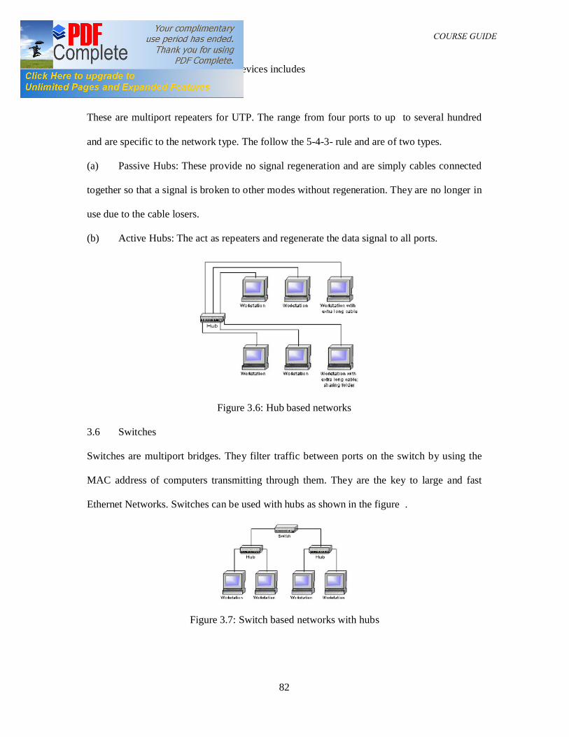
DAM 361 COURSE GUIDE
82
Examples of other internetworking devices includes
3.5 Ethernet Hubs:
These are multiport repeaters for UTP. The range from four ports to up to several hundred
and are specific to the network type. The follow the 5-4-3- rule and are of two types.
(a) Passive Hubs: These provide no signal regeneration and are simply cables connected
together so that a signal is broken to other modes without regeneration. They are no longer in
use due to the cable losers.
(b) Active Hubs: The act as repeaters and regenerate the data signal to all ports.
Figure 3.6: Hub based networks
3.6 Switches
Switches are multiport bridges. They filter traffic between ports on the switch by using the
MAC address of computers transmitting through them. They are the key to large and fast
Ethernet Networks. Switches can be used with hubs as shown in the figure .
Figure 3.7: Switch based networks with hubs
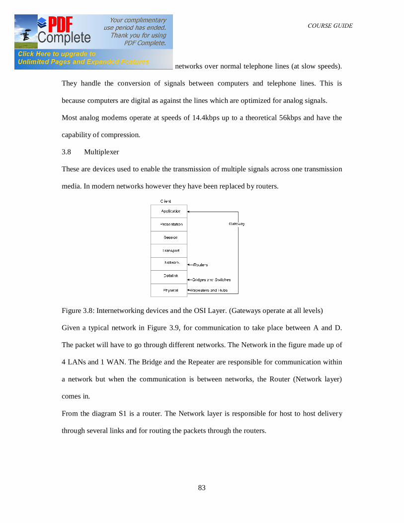
DAM 361 COURSE GUIDE
83
3.7 Modems
These are small devices that connect networks over normal telephone lines (at slow speeds).
They handle the conversion of signals between computers and telephone lines. This is
because computers are digital as against the lines which are optimized for analog signals.
Most analog modems operate at speeds of 14.4kbps up to a theoretical 56kbps and have the
capability of compression.
3.8 Multiplexer
These are devices used to enable the transmission of multiple signals across one transmission
media. In modern networks however they have been replaced by routers.
Figure 3.8: Internetworking devices and the OSI Layer. (Gateways operate at all levels)
Given a typical network in Figure 3.9, for communication to take place between A and D.
The packet will have to go through different networks. The Network in the figure made up of
4 LANs and 1 WAN. The Bridge and the Repeater are responsible for communication within
a network but when the communication is between networks, the Router (Network layer)
comes in.
From the diagram S1 is a router. The Network layer is responsible for host to host delivery
through several links and for routing the packets through the routers.
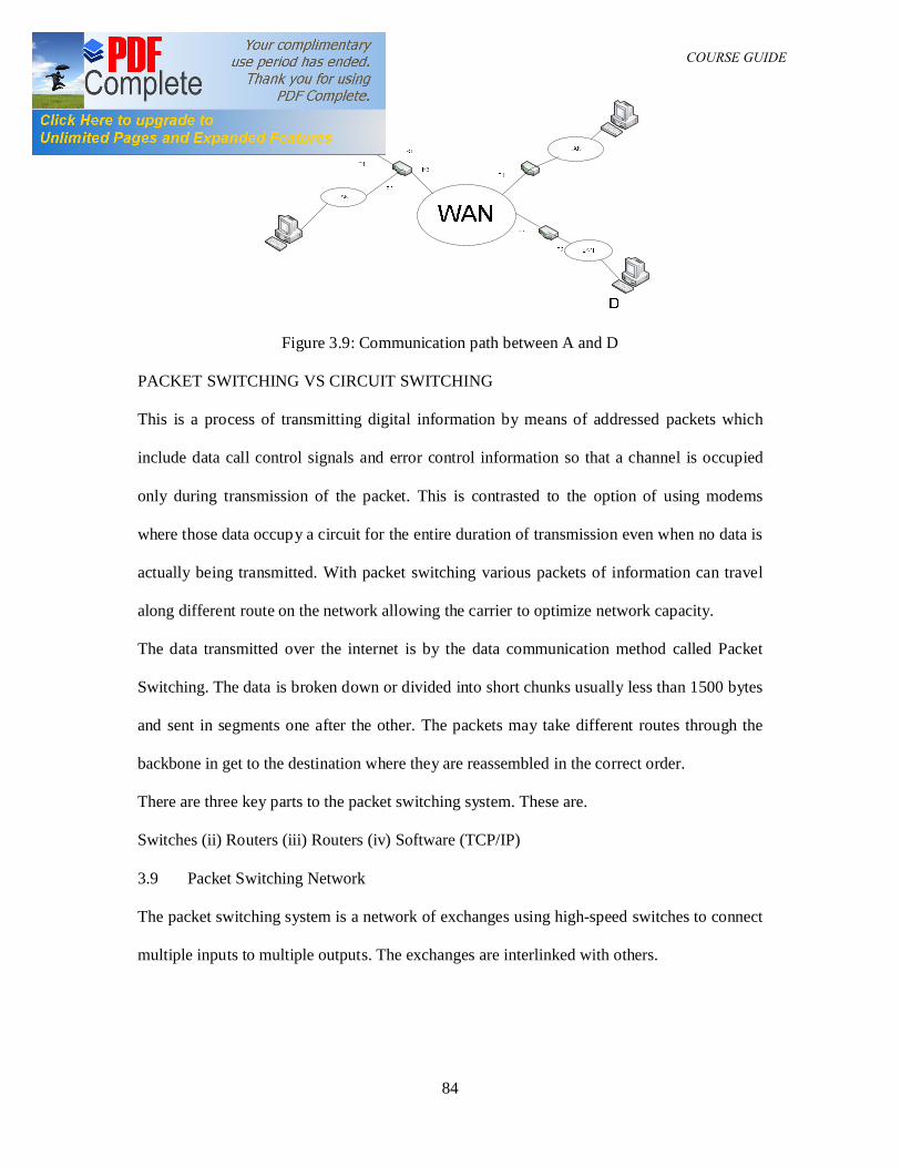
DAM 361 COURSE GUIDE
84
Figure 3.9: Communication path between A and D
PACKET SWITCHING VS CIRCUIT SWITCHING
This is a process of transmitting digital information by means of addressed packets which
include data call control signals and error control information so that a channel is occupied
only during transmission of the packet. This is contrasted to the option of using modems
where those data occupy a circuit for the entire duration of transmission even when no data is
actually being transmitted. With packet switching various packets of information can travel
along different route on the network allowing the carrier to optimize network capacity.
The data transmitted over the internet is by the data communication method called Packet
Switching. The data is broken down or divided into short chunks usually less than 1500 bytes
and sent in segments one after the other. The packets may take different routes through the
backbone in get to the destination where they are reassembled in the correct order.
There are three key parts to the packet switching system. These are.
Switches (ii) Routers (iii) Routers (iv) Software (TCP/IP)
3.9 Packet Switching Network
The packet switching system is a network of exchanges using high-speed switches to connect
multiple inputs to multiple outputs. The exchanges are interlinked with others.
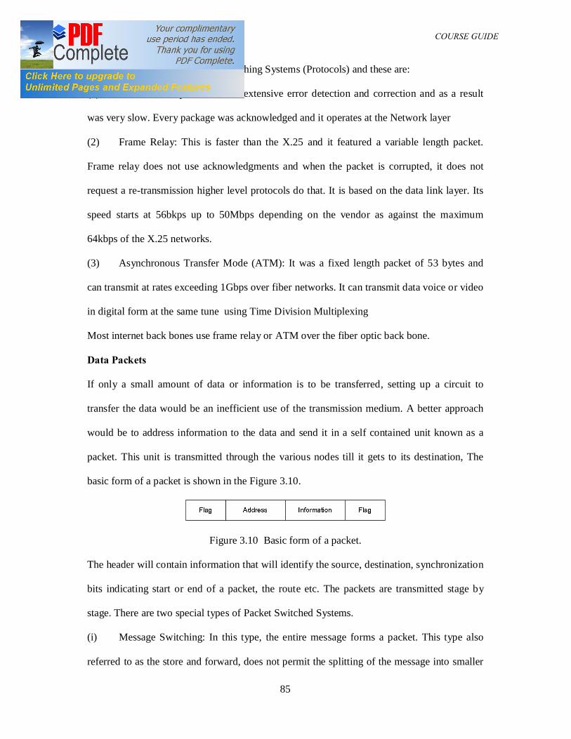
DAM 361 COURSE GUIDE
85
These are three popular Packet Switching Systems (Protocols) and these are:
(1) X.25 – This system utilized extensive error detection and correction and as a result
was very slow. Every package was acknowledged and it operates at the Network layer
(2) Frame Relay: This is faster than the X.25 and it featured a variable length packet.
Frame relay does not use acknowledgments and when the packet is corrupted, it does not
request a re-transmission higher level protocols do that. It is based on the data link layer. Its
speed starts at 56bkps up to 50Mbps depending on the vendor as against the maximum
64kbps of the X.25 networks.
(3) Asynchronous Transfer Mode (ATM): It was a fixed length packet of 53 bytes and
can transmit at rates exceeding 1Gbps over fiber networks. It can transmit data voice or video
in digital form at the same tune using Time Division Multiplexing
Most internet back bones use frame relay or ATM over the fiber optic back bone.
Data Packets
If only a small amount of data or information is to be transferred, setting up a circuit to
transfer the data would be an inefficient use of the transmission medium. A better approach
would be to address information to the data and send it in a self contained unit known as a
packet. This unit is transmitted through the various nodes till it gets to its destination, The
basic form of a packet is shown in the Figure 3.10.
Figure 3.10 Basic form of a packet.
The header will contain information that will identify the source, destination, synchronization
bits indicating start or end of a packet, the route etc. The packets are transmitted stage by
stage. There are two special types of Packet Switched Systems.
(i) Message Switching: In this type, the entire message forms a packet. This type also
referred to as the store and forward, does not permit the splitting of the message into smaller
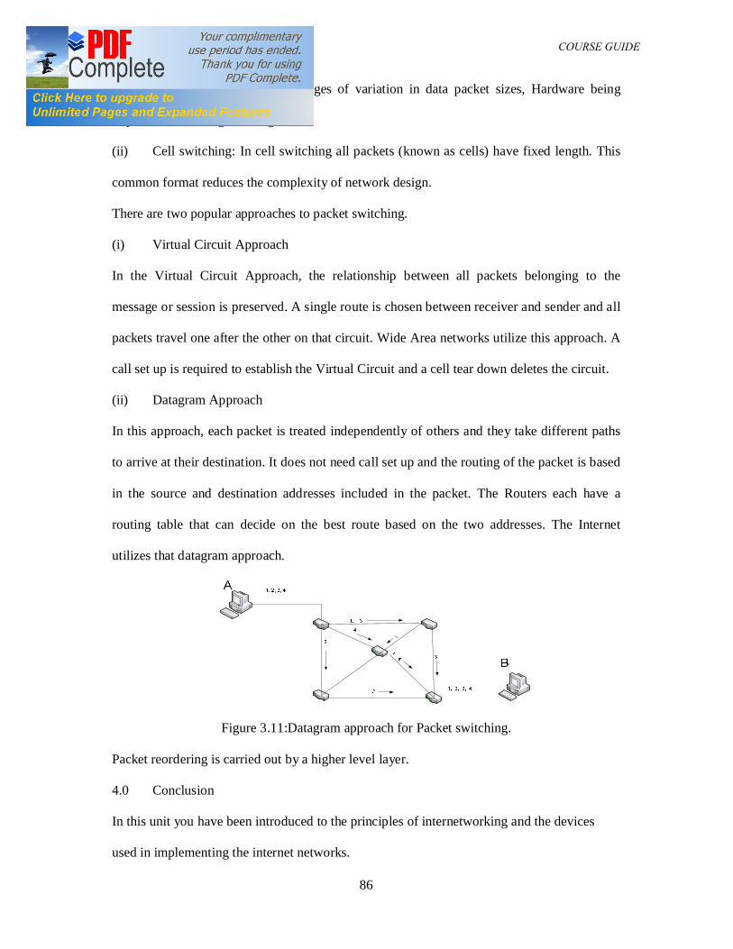
DAM 361 COURSE GUIDE
86
packets and this has the disadvantages of variation in data packet sizes, Hardware being
required to store large messages etc.
(ii) Cell switching: In cell switching all packets (known as cells) have fixed length. This
common format reduces the complexity of network design.
There are two popular approaches to packet switching.
(i) Virtual Circuit Approach
In the Virtual Circuit Approach, the relationship between all packets belonging to the
message or session is preserved. A single route is chosen between receiver and sender and all
packets travel one after the other on that circuit. Wide Area networks utilize this approach. A
call set up is required to establish the Virtual Circuit and a cell tear down deletes the circuit.
(ii) Datagram Approach
In this approach, each packet is treated independently of others and they take different paths
to arrive at their destination. It does not need call set up and the routing of the packet is based
in the source and destination addresses included in the packet. The Routers each have a
routing table that can decide on the best route based on the two addresses. The Internet
utilizes that datagram approach.
Figure 3.11:Datagram approach for Packet switching.
Packet reordering is carried out by a higher level layer.
4.0 Conclusion
In this unit you have been introduced to the principles of internetworking and the devices
used in implementing the internet networks.
DAM 361 COURSE GUIDE
87
5.0 Summary
In this unit we have been able to extend knowledge of the theory of computer networks by a
study of the internetworking devices and their places in networks.
6.0 Tutor marked assignment
(1) Write short notes on ant three internetworking devices and state their location in the
network architecture
(2) Define Packet switching and write short notes on any two packet switching based
network technologies
7.0 References
1. Data Communications and Networking, Forouzan, B. A, 3rd Ed. (2004),
McGraw-Hill.
2. Computer Communications and Networking Technologies, M.A. Gallo and W.M
Hancock, (2002), Brooks/Cole.
3. Business Data Communications & Networking, Fitzgerald & Dennis, 6th
Ed. (1999),
John Wiley & Sons
4. Data and Computer Communications, Stallings W, 5th
Ed. (1997), Prentice Hall, NJ,
5. Business Data Communications and Networking, Fitzgerald and Dennis, ,John
Wiley and Sons, 7th Edition, 2002
6. Applied Data Communications: A Business-Oriented Approach, 4th Edition Goldman
James E. & Rawles Phillip T, John Wiley & Sons, 2003
7. Comer, Douglas E., Computer Networks and Internets, Second Edition, Prentice-Hall
International,Inc., N.J. (1999).
8. Computer Networks, 4th Edition by Andrew S. Tanenbaum
9 TCP/IP for Windows2000 by Houde and Hoffman.
DAM 361 COURSE GUIDE
88
UNIT NINE: NETWORK MANAGEMENT
Table of contents
1.0 Introduction
2.0 Course objectives
3.0 Network Management
3.1 Simple Network Management Protocol
4.0 Conclusions
5.0 Summary
6.0 Tutor Marked Assignment
7.0 References
1.0 Introduction
Network management involves configuring, monitoring and possibly reconfiguring
components in a network with the goal of providing optional performances, minimal down
time, proper security, accountability and flexibility.
This type of management is usually accomplished by the use of a Network Management
System which contains a software bundle designed to improve the overall performance and
reliability of the system. In the small networks, network management systems is used to
identify users who represent security hazards while for large systems, resource usage can be
tracked for the purposes of accounting and charging. The most common computer network
management system currently being implemented is known as the SIMPLE NETWORK
MANAGEMENT PROTOCOL (SNMP).
The compounds that make up the system are usually from different vendors, so a network
management system must be based on standards so that inter-operability and compatibility
can be ensured.
DAM 361 COURSE GUIDE
89
2.0 Course Objective
At the end of this unit, the students are expected to be able to
(1) Discuss the principles of Network management
(2) Discuss the Simple Network Management Protocol
3.0 Network Management
Network management is a collection of tasks and responsibilities involved in maintaining a
network. It can be broken down into five distinct categories.
1. Account management:- This is the gathering of information on which user or
departments on the network is employing which network resource and determine
better resource allocation.
2. Fault management:- This include troubleshooting, finding and correcting failed or
damaged components, monitoring equipment for early problem indicators and
tracking down distributed problems. It involves reconfiguring a network during faults
to maintain the required service level.
3. Security: - This includes authorization, access control data encrypting and
management of encrypting keys.
4. Configuration management: - This tracks hardware and software information such as
the day to day monitoring and maintenance of the current physical and logical state of
the network as well as registration and recognition of applications and services on the
network.
5. Performance: - This involves the monitoring of the traffic on the network.
Most of these network management platforms are proprietary and as such, the use of
computer network components by different vendors makes the use of such platforms
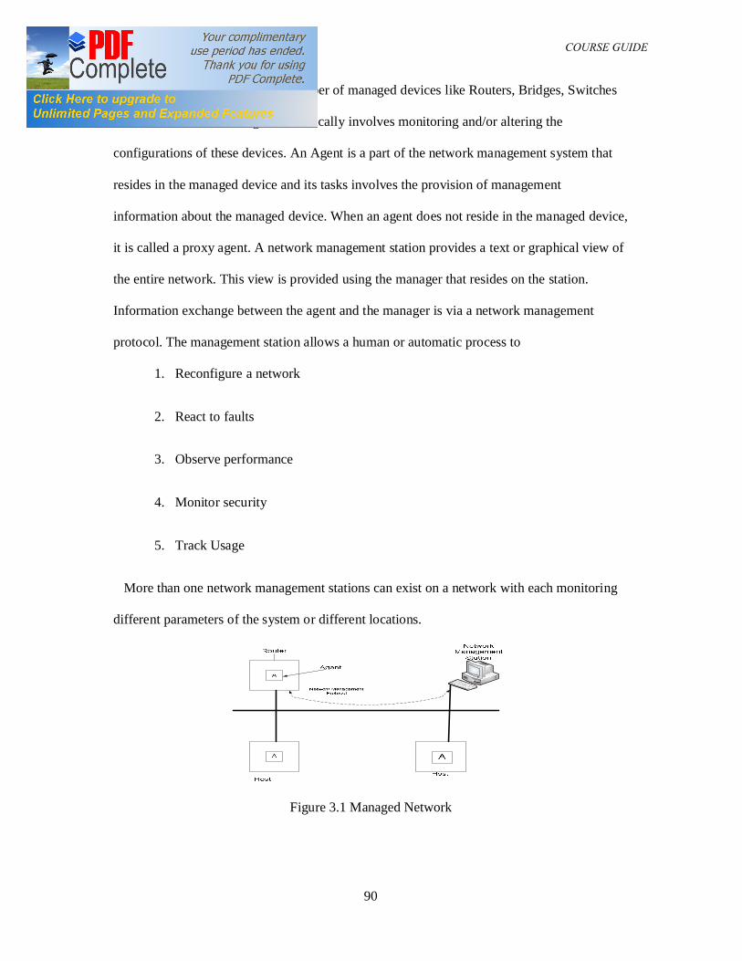
DAM 361 COURSE GUIDE
90
complex. A network contains a number of managed devices like Routers, Bridges, Switches
and hosts. Network management basically involves monitoring and/or altering the
configurations of these devices. An Agent is a part of the network management system that
resides in the managed device and its tasks involves the provision of management
information about the managed device. When an agent does not reside in the managed device,
it is called a proxy agent. A network management station provides a text or graphical view of
the entire network. This view is provided using the manager that resides on the station.
Information exchange between the agent and the manager is via a network management
protocol. The management station allows a human or automatic process to
1. Reconfigure a network
2. React to faults
3. Observe performance
4. Monitor security
5. Track Usage
More than one network management stations can exist on a network with each monitoring
different parameters of the system or different locations.
Figure 3.1 Managed Network
DAM 361 COURSE GUIDE
91
The Manager can poll each of the agents to access information and the managed device e.g.,
the manager polling the agent on the Router to access the number of packets transmitted from
any Host.
Network Management System can operate in any of the two manners listed below:
(1) Centralized: In this case one computer system runs most of the applications required
for network management.
(2) Distributed: In this approach, several peer network management systems run
simultaneously with each monitoring a specific part of the network. The systems may be
distributed geographically.
The current standard supported by most vendors today is the Simple Network Management
Protocol. It is limited in functions but provides for vendor independent expansion.
3.1 Simple Network Management Protocol
The Simple Network Management Protocol was developed by the Internet Engineering
Taskforce (IETF).This group is a large open community of individuals, network designers
operators, vendors and researchers. The SNMP has only three elements and these are
(i) The Manager (ii) The Agent (iii) The Management Information Base
The Agent
The Agent is usually located on a network station and can only perform operations under the
direction of the manager. The agent gathers and maintains certain information about its host
and the information is stored is contained in the Management Information Base (MIB).
The Manager
The Manager queries the network node for information. This information is supplied through
the User Datagram Protocol (UDP).
DAM 361 COURSE GUIDE
92
The SNMP is an open standard with a weak security but very high level of compatibility. It is
an application layer protocol based on asynchronous request response protocol meaning that
there is no need to wait for response before sending other messages.
The SNMP provides three ways to access the Management Information.
(1) Manager sends a request to the agent to other retrieve or modify the management
information associated with the network device in question using one of the following
requests.
(a) Get Request: PDU – for requesting information on specific variables
(b) Get Next Request – PDU – for requesting for next set of information
(c) Get Bulk Request – PDU – for requesting bulk information retrieval
(d) Set Request – PDU – for creating or modifying management information
The agent must always reply using a respond – PDU
(2) Manager sends a request to another manager for information associated with that
manager.
(3) Unconfirmed interaction in which an agent sends an unsolicited Trap-PDU to a manager
notifying the manager of an exceptional situation that has resulted in changes to the
management information associated with the network device.
The Management Information Base
This is a virtual data based use to define the functional and operational aspects of the network
device. The database contains an object for each functional aspect of a device that needs to be
managed.
Each definition of a particular object contains information about the object name, data type, a
human readable description, type of access (read/write) and an object identify.
DAM 361 COURSE GUIDE
93
Example of an object:
IP Errors – Object Type
Syntax – Counter
Access - Read Only
Status - Mandatory
Description - ‘The number of input datagram discarded due to errors in their IP
headers and other errors etc”.
The manager uses the Managed Information to access the statistics of the number of IP
packets that is discarded due to various errors.
4.0 Conclusions
In this unit you have been introduced to the principles of network management and the tasks
involved in network management. The Simple network management protocol has also been
discussed
5.0 Summary
In this unit we have been able to extend knowledge of the theory of computer networks by a
study of the network management principles and a network management protocol.
6.0 Tutor marked assignment
(1) Write short notes on network management and discuss any four tasks and
responsibilities involved in maintaining a network.
(2) Describe the principles of Network management based on the Simple Network
Management Protocol
DAM 361 COURSE GUIDE
94
7.0 References
1. Data Communications and Networking, Forouzan, B. A, 3rd Ed. (2004),
McGraw-Hill.
2. Computer Communications and Networking Technologies, M.A. Gallo and W.M
Hancock, (2002), Brooks/Cole.
3. Business Data Communications & Networking, Fitzgerald & Dennis, 6th
Ed. (1999),
John Wiley & Sons
4. Data and Computer Communications, Stallings W, 5th
Ed. (1997), Prentice Hall, NJ,
5. Business Data Communications and Networking, Fitzgerald and Dennis, ,John
Wiley and Sons, 7th Edition, 2002
6. Periodical and Technical References of Text book by Goldman
http://www.wiley.com/college/goldman/ref.html
7. Computer Networks, 4th Edition by Andrew S. Tanenbaum
8. Computer Communications and Networking Technologies by Michael A. Gallo,
William M. Hancock
9. Business Data Communications and Networking, 7th Edition
Jerry FitzGerald, Alan Dennis
10 Business Data Networks and Telecommunications, fourth edition, by Raymond R.
Panko.
11 TCP/IP for Windows2000 by Houde and Hoffman.
DAM 361 COURSE GUIDE
95
MODULE FOUR
UNIT TEN: BUSINESS ORGANIZATIONS
Table of contents
1.0 Introduction
2.0 Course objectives
3.0 Forms of Business
3.1 Sole proprietorships
3.2 Partnerships
3.3 Limited Liability Partnerships
3.4 Companies
3.5 Business Trust
4.0 Conclusions
5.0 Summary
6.0 Tutor Marked Assignment
7.0 References
1.0 Introduction
A Business is a legally recognized organization setup to provide goods and services to
consumers with aim of making profit. It is also called a company, firm and enterprise.
Businesses are predominant in economies with most of them being privately owned and
formed to make profit that will increase the wealth of its owners and grow the business itself.
The receipt or generation of a financial return in exchange for work and acceptance of risk is
the main objective for the setting up of a business organization. Notable exceptions include
cooperative enterprises and state-owned enterprises. Socialist systems involve government,
public ownership, state-ownership or direct worker ownership of enterprises and assets that
DAM 361 COURSE GUIDE
96
would be run as businesses in a capitalist economy. The distinction between these institutions
and a business is that socialist institutions often have alternative or additional goals aside
from maximizing or turning a profit.
2.0 Course Objectives
At the end of this unit students are expected to
(1) Itemize the principles of the sole proprietorship business organization
(2) List the principles of the partnership based business organization
(3) Discuss the principle of limited liability type of business organization
3.0 Forms of Business Organizations
A business organization can be classified into 5 major groups. These groups are
• A Sole Proprietorship
• A Partnership
• A Limited Liability Partnership
• A Company
• A Business Trust
3.1 SOLE PROPRIETORSHIPS
A Sole Proprietorship is defined as a business that is owned and wholly financed by an
individual on his or her own.It is the simplest form of business organization. The law regards
the sole proprietorship business and its owner as one and the same entity. As such, all rights
that the business has are rights that belong to the proprietor and liabilities or debts that are
incurred by the business are in law the liabilities or debts of the proprietor. The assets and
profits that the business generates are owned by the proprietor who is personally liable to pay
whatever tax payable in respect of these assets and profits. Should the proprietor die, the
business will cease to exist.

DAM 361 COURSE GUIDE
97
To carry out a business as a sole proprietor in Nigeria, he or she must first apply to register
the business in accordance with the provisions of the Corporate Affairs Commission (CAC)
In Nigeria. This may be done by completing and submitting the relevant forms to the nearest
CAC office. Subsequently, the proprietor must comply with all the requirements set out under
the Business Registration Act.
3.2 PARTNERSHIPS
A Partnership is formed where two or more persons carry on a business in common with a
view to making profit. Generally, the maximum number of partners allowed in a partnership
is 20. The partners can either be individuals or corporate bodies. Should more than 20
persons wish to carry on business together, they will have to do so through a Company. A
business partnership is also called a ‘firm’.
The law treats a partnership as the same legal entity as its partners. The partners collectively
own the assets of the partnership and are each individually liable for the debts and liabilities
of the partnership. Each partner is personally liable for the full amount of debt owed by the
partnership without any limit. Partners are taxed individually on their share of the
partnership’s profits. So long as there exists a relationship where two or more persons carry
on business in common with a view to making profit, the law will recognize the existence of
a partnership. In most situations, partnerships are created through a partnership agreement
entered into by the partners in the business. The agreement may be made orally or in writing.
Relationships between partners
The relationship between partners is governed by the partnership agreement.The main
elements usually found in such an agreement include details of:
• How profits and liabilities of the firm should be shared amongst the partners;
• The responsibilities of the various partners for the running of the business;
• The obligations that the partners have to each other (e.g. to render proper accounts);

DAM 361 COURSE GUIDE
98
• How a partner may leave the firm; and
• How the residual assets of the firm should be distributed should the partnership be
dissolved.
Partners are agents of each other and of the firm. A partner’s acts in relation to the normal
business operations of the firm will be treated as being the actions of the firm and all its
partners. While the authority of any individual partner may be restricted by agreement, such a
restriction will not affect an outside party dealing with the partner unless the restriction is
known by that party or that party either does not know or believe that the person he is dealing
with is a partner of the firm.
Liability of Partners
The partners are each (if dead, his estate) liable for all debts and obligations of the firm that
have been incurred while he is a partner of the firm. The firm and all its partners may also be
sued for any wrongful act committed by any partner in the course of the business of the firm
or with the authority of his co-partners.
Dissolution of Partnerships
A partnership will automatically be dissolved should any partner die or leave the firm. The
partnership agreement may also provide for other instances in which the partnership is to be
dissolved. This may include situations where any one of the partners becomes bankrupt or
becomes of unsound mind. It is also possible for an application to be made to the Court to
have the partnership dissolved under circumstances specified in the CAC laws
3.3 LIMITED LIABILITY PARTNERSHIP
A Limited Liability Partnership (‘LLP’) is a business organization comprising two or more
persons associated for carrying on a lawful business with an objective of making profit
.Despite its name, it is not regarded as a partnership and general partnership law does not
apply to LLPs. The LLP is a corporate body that has a separate legal personality. It can sue,

DAM 361 COURSE GUIDE
99
be sued and own property in its own name. The LLP is liable for its own debts and the
partners and managers of the LLP cannot be made liable for such debts. Each of the partners
are assessed and taxed individually on their respective share of the profits in the LLP.Every
partner of the LLP is regarded as an agent of the LLP. However, the LLP is not bound by the
acts of a partner which are not authorized where either this fact is known to the person
dealing with the partner or the person does not know or believe the partner to be a partner in
the LLP.
Formation of a Limited Liability Partnership
An LLP is formed by registration under the Limited Liability Partnership laws. It must have a
minimum of two partners. There is no limit on the number of partners that an LLP may have .
The partners can either be individuals or corporations.
Relation of Partners to Each Other
The relationships amongst partners in an LLP are governed by the Limited liability
partnership agreement. A partner will cease to be a partner in an LLP upon death or
dissolution. In such an event, the LLP is required to pay to the former partner (or his legal
representative or its liquidator) an amount equal to the former partner’s capital contribution to
the LLP and the former partner’s share in the accumulated profits of the LLP. The amount is
determined as at the date the former partner ceased to be a partner.
3.4 COMPANIES
A Company is an entity that is registered with the CAC. It has its own legal personality that
is distinct from its members and the persons who manage the company. Companies can
therefore own property and sue or be sued in their own names. They are recognized as
taxable entities in their own right.
DAM 361 COURSE GUIDE
100
Types of Companies
Companies may be classified according to whether they are “private” or “public” as well as
according to their members’ liability.
(1) Private Companies
A private company is one whose memorandum or articles of association:
• restricts the right of its members to transfer their shares in the company; and
• limits the number of members that the company can have to not more than 50.
The restriction on the right to transfer shares in a private company usually takes the form of a
requirement that the transfer be first approved by the company’s board of directors or a
requirement that the shares be first offered to be transferred to existing shareholders.
(2) Public Companies
Any company that is not a private company is a public company. Public companies may or
may not be listed on a stock exchange. Where they are so listed, they are usually referred to
as “listed companies” and have to comply with the rules and regulations of the stock
exchange on which they are listed.
Formation of Companies
A company comes into existence upon registration under the Corporate Affairs Commission.
It can have a minimum of 1 member. Theoretically, there is no limit to the number of
members that a company can have. The members can be individuals or corporations. The
governance structure of a company and the interrelationship between the company, its
members and its managers is governed by the Company’s constitutional documents (the
Memorandum of Association and the Articles of Association) as well as by the provisions of
the Corporate Affairs Commission Companies Act. The members of companies (usually in
joint venture arrangements) enter into ‘shareholder agreements’ as amongst themselves to

DAM 361 COURSE GUIDE
101
capture some of their key rights and obligations in relation to how the company is to be
structured and managed.
Membership of companies
A person can become a member either by subscribing for shares in the company during
public offers or by purchasing the company’s shares from another person. Members of a
company are most commonly referred to as shareholders. The rights and obligations of the
members in relation to each other and to the company are found in the companies Act as well
as in the company’s constitutional documents. The main rights that members have include:
• The right to be given notice of and to attend and participate in general meetings of
members;
• The right to be treated fairly and to have the provisions of the company’s constitutional
documents complied with.
• The right to make some key decisions in relation to the company through the general
meeting (these include matters such as the appointment and removal of directors and auditors
of the company; the issue of shares and the amendment of the company’s constitutional
documents);
• The right to a share of declared dividends (dividends can only be declared out of available
profits); and
• The right to have the company wound up in specified circumstances and
to share in the residual assets of the company.
Members are not liable for the debts of the company.
3.5 BUSINESS TRUSTS
A ‘trust’ may be described as an arrangement where a person (called the ‘trustee’) holds
property for the benefit of others (called ‘beneficiaries’). A Business Trust is a trust that
operates and runs a business enterprise. It is not a separate entity in that the trustee of the
DAM 361 COURSE GUIDE
102
business trust is regarded as the legal owner of the assets in the trust. Under the general law
of trust, the beneficiaries of the trust are liable for the legal obligations of the trust. A
business trust can distribute its operating cash flows to its beneficiaries. Depending on the
circumstances and how the trust is structured, tax may be payable either on profit made by
the trust or by the beneficiaries on their respective shares in the profit under the trust.
4.0 Conclusion
In this unit you have been introduced to the different forms of business organization and the
characteristics of each.
5.0 Summary
In this unit we have been able to introduce the different forms of business organization and
the principles of operation of each.
6.0 Tutor marked assignment
(1) Give a brief description of three forms of business organizations stating two
advantages of each
(2) List four advantages of Partnerships over sole proprietorships.
7.0 References
(1) Meredith G.G Small Business management in Australia. McGraw-Hill 1982
(2) Perry C and Pendleton W. Successful Small Business Management. Pitman 1983
(3) Petty J.W., Kewone A.J., Scott D.F and Martin J.D. Basic Financial Management.
Prentice hall 1985
DAM 361 COURSE GUIDE
103
UNIT ELEVEN: MARKETING
Table of contents
1.0 Introduction
2.0 Course objectives
3.0 Market Orientations
3.1 Marketing Mix
3.2 The Marketing Environment
3.3 Marketing Research
3.4 Marketing Communication
4.0 Conclusions
5.0 Summary
6.0 Tutor Marked Assignment
7.0 References
1.0 Introduction
Marketing as defined by the American Marketing Association is the activity, set of
institutions, and processes for creating, communicating, delivering, and exchanging offerings
that have value for customers, clients, partners, and society at large. The term developed from
the original meaning which referred literally to going to market, as in shopping, or going to a
market to buy or sell goods or services.
The definition of the Chartered Institute of Marketing is that Marketing is the "The
management process responsible for identifying, anticipating and satisfying customer
requirements profitably." The Marketing process starts with marketing research and goes
through market segmentation, business planning and execution, ending with pre and post-
sales promotional activities.
DAM 361 COURSE GUIDE
104
2.0 Course Objective
At the end of this unit, students are expected to
(1) Discuss the basic concepts of Marketing
(2) Discuss the Principles of Market Orientations
(3) Discuss the different factors relating to the Market environment
(4) Discuss the principles of Market research.
3.0 Marketing orientations
In marketing, an orientation, relates to a perception or attitude a firm holds towards its
product or service, essentially concerning consumers and end-users. There are different types
of orientations and they are discussed below.
(1) Product orientation
Product orientation ensures that the firm is mainly concerned with the quality of its own
product. The central assumption of the firm is that as long as its product is of high standard,
its product will always be in high demand.
(2) Sales orientation
Sales orientation causes the firm to focus primarily on the selling/promotion of a particular
product. This orientation entails simply selling an already existing product, and using
promotion techniques to attain the highest sales possible.
(3) Production orientation
Production orientation causes the firm to specialize in producing as much as possible of a
given good. Thus, the firm exploits economies of scale. A production orientation may be
DAM 361 COURSE GUIDE
105
deployed when a high demand for a good exists, coupled with a good certainty that consumer
tastes do not rapidly alter (similar to the sales orientation).
(4) Marketing orientation
The marketing orientation is the most common orientation used in contemporary marketing.
It involves a firm essentially basing its marketing plans around the marketing concept, and
thus forging products to suit new consumer tastes. The marketing orientation often has three
prime facets, which are:
Customer orientation
A company in the market economy survives by producing goods that consumers are willing
and able to buy.
Organizational orientation
In this orientation, all departments of the firm are geared to satisfying consumer wants/needs.
The firm’s marketing department is often seen as of prime importance within the functional
level of the organization.
3.1 The Marketing Mix
Professor Neil Borden at Harvard Business School identified a number of company
performance actions that can influence the consumer decision to purchase goods or services.
These actions are represented in a Marketing Mix. The Marketing Mix is made up of 4
elements. These are product, price, place and promotion.
• Product: This deals with the actual specifications of the goods and services and how it
satisfies the consumer’s needs and wants. The scope of a product generally includes
supporting elements such as warranties, guarantees, and support.
DAM 361 COURSE GUIDE
106
• Pricing: This refers to the process of setting a price for a product, including discounts.
The price may not be monetary; it can be what is exchanged for the product or
services, e.g. time, energy, or attention.
• Placement: This refers to how the product gets to the customer; for example, point-of-
sale placement or retail process. This P is also sometimes been called Place, referring
to the channel by which a product or service is sold (e.g. online vs. retail), which
geographic region or industry, to which segment (young adults, families, business
people), etc.
• Promotion: This includes the advertising, sale promotion, promotional education,
publicity and personal selling and branding. Branding refers to the various methods of
promoting the product, brand or company.
These four elements are often used to develop a marketing plan.
3.2 The marketing environment
The term "marketing environment" relates to all of the factors (internal, external, direct or
indirect) that affects a firm's marketing decision-making/planning. A firm's marketing
environment consists of three main areas and these are:
• The macro-environment, over which a firm holds little control
• The micro-environment, over which a firm holds a greater amount (though not
necessarily total) control
• The internal environment
The macro-environment
The marketing macro-environment of a firm consists of a variety of external factors that
manifest on a large scale. These factors are typically economic, social, political or
DAM 361 COURSE GUIDE
107
technological in nature and are assessed using the PESTLE analysis. The PESTLE analysis
is a combination of the Political, Economic, Social, Technological, Legal, Ecological
analysis, within this analysis ,a firm would analyze national political issues, culture and
climate, key macroeconomic conditions, health and indicators (such as economic growth,
inflation, unemployment, etc.), social trends/attitudes, and the nature of technology's impact
on its society and the business processes within the society.
The micro-environment
The marketing micro-environment of a firm consists of factors relating to the firm itself, or
stakeholders closely connected with the firm.
3.3 Marketing research
Marketing research involves the conduct of research to support marketing activities, and the
statistical interpretation of acquired data into information. This information is then used by
managers to plan marketing activities, gauge the nature of a firm's marketing environment,
attain information from suppliers, etc. This differ from Market research. Market research
pertains to research in a given market. As an example, a firm may conduct research in a target
market, after selecting a suitable market segment. In contrast, marketing research relates to all
research conducted within marketing. Thus, market research is a subset of marketing
research. Marketing researchers use different statistical methods to interpret their findings
and convert data into information.
3.4 Marketing communications
Marketing communications breaks down the strategies involved with marketing messages
into categories based on the goals of each message. There are distinct stages in converting
strangers to customers that govern the communication medium that should be used. There are
DAM 361 COURSE GUIDE
108
two main approaches utilized in marketing communication. These are Personal sales and
Sales promotion
4.0 Conclusion
In this unit the principles and advantages of the marketing has been discussed. The different
factors relating to marketing have also been discussed.
5.0 Summary
This Unit has explored the principles of marketing and the associated advantages and
concepts related to marketing.
6.0 Tutor Marked Assignment
(1) Define Marketing and discuss the four Ps that constitute the marketing Mix
(2) Write short notes on any three factors that affect the marketing environment of a firm
7.0 References
Sales Process Engineering: A Personal Workshop.Paul H. Selden (1997) Milwaukee,
WI: ASQ Quality Press. p. 23.
"The Concept of the Marketing Mix" from the Journal of Advertising Research, June
1964 pp 2-7
"Marketing Management: Strategies and Programs", Guiltinan et al., McGraw
Hill/Irwin, 1996
DAM 361 COURSE GUIDE
109
UNIT TWELVE MARKETING PLAN
Table of contents
1.0 Introduction
2.0 Course objectives
3.0 The Marketing Plan Process
3.1 Marketing Planning Objectives
3.2 Detailed Plans and Programs
3.3 Content of The marketing Plan
3.4 Measurement of Progress
3.5 Performance Analysis
3.6 Use of Marketing Plans
4.0 Conclusions
5.0 Summary
6.0 Tutor Marked Assignment
7.0 References
1.0 Introduction
A Marketing plan is a carefully developed and written document that specifies the details of
the required actions needed to achieve one or more marketing objectives. It can be for a
product or service , a brand or a product line Marketing plans can span a period of up to five
years.
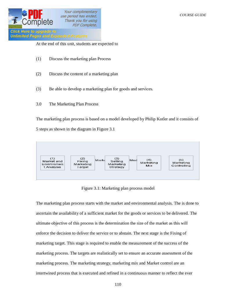
DAM 361 COURSE GUIDE
110
2.0 Course Objectives
At the end of this unit, students are expected to
(1) Discuss the marketing plan Process
(2) Discuss the content of a marketing plan
(3) Be able to develop a marketing plan for goods and services.
3.0 The Marketing Plan Process
The marketing plan process is based on a model developed by Philip Kotler and it consists of
5 steps as shown in the diagram in Figure 3.1
Figure 3.1: Marketing plan process model
The marketing plan process starts with the market and environmental analysis. The is done to
ascertain the availability of a sufficient market for the goods or services to be delivered. The
ultimate objective of this process is the determination the size of the market as this will
enforce the decision to deliver the service or to abstain. The next stage is the Fixing of
marketing target. This stage is required to enable the measurement of the success of the
marketing process. The targets are realistically set to ensure an accurate assessment of the
marketing process. The marketing strategy, marketing mix and Market control are an
intertwined process that is executed and refined in a continuous manner to reflect the ever
DAM 361 COURSE GUIDE
111
changing realities of the market taking into consideration the effect of competitors, economic
indices among other factors etc.
For a plan to be effective, it has to be formalized usually in written form, as a formal
"marketing plan." The essence of the process is that it moves from the general to the specific;
from the overall objectives of the organization down to the individual action plans. It is also
an interactive process, so that the draft output of each stage is checked to see what impact it
has on the earlier stages - and is amended.
3.1 Marketing planning objectives
The marketing objectives is based on the organization's financial objectives; converting these
financial measurements into the related marketing measurements. Marketing strategies can be
defined as the means by which marketing objectives will be achieved The following key
points are the factors that determine the manner the marketing strategy is structured. These
are:
1. Price - The amount of money needed to buy products
2. Product - The actual product
3. Promotion (advertising)- Getting the product known
4. Placement - Where the product is located
5. People - Represent the business
6. Physical environment - The ambiance, mood, or tone of the environment
7. Process - How do people obtain your product
8. Packaging - How the product will be protected
To be effective, the objectives should be capable of measurement and therefore be
quantifiable. This measurement may be in terms of sales volume, money value, market share,
DAM 361 COURSE GUIDE
112
percentage penetration of distribution outlets and so on. An example of such a measurable
marketing objective might be "to enter the market with particular product or service and
capture a particular percent of the market for that product or service within a defined time
frame. As it is quantified it can, within limits, be unequivocally monitored; and feedback
gotten from results can be used to take any necessary action required to maintain or improve
on the targets set out in the marketing plan as the need arises.
3.2 Detailed plans and programs
At this stage, the strategies are developed into detailed plans and program. The focus of the
plans will be determined by the organization's specific strategies. A product-oriented
company will focus its plans for the 7 P's around each of its products. A market or
geographically oriented company will concentrate on each market or geographical area. Each
will base its plans upon the detailed needs of its customers, and on the strategies chosen to
satisfy these needs.
A critical part of the detailed plan involves the exact plans, programs and individual activities
will take place over the period of the plan. Without these specified - and preferably quantified
- activities the plan cannot be monitored, even in terms of success in meeting its objectives. It
is these programs and activities which will then constitute the "marketing" of the organization
over the period. These detailed marketing programs are the most important, practical outcome
of the whole planning process. These plans are therefore required to be:
• Clear - They should be an unambiguous statement of 'exactly' what is to be done.
• Quantified - The predicted outcome of each activity should be, as far as possible,
quantified; so that its performance can be monitored.
DAM 361 COURSE GUIDE
113
• Focused - The temptation to proliferate activities beyond the numbers which can be
realistically controlled should be avoided.
• Realistic - They should be achievable.
• Agreed - Those who are to implement them should be committed to them, and agree
that they are achievable. The resulting plans should become a working document
which will guide the campaigns taking place throughout the organization over the
period of the plan.
3.3 Content of the marketing plan
A marketing plan for a small business typically includes the level of demand for the product
or service and the strengths and weaknesses of competitors: The content includes
1. Description of the product or service, including special features
2. Marketing budget, including the advertising and promotional plan
3. Description of the business location, including advantages and disadvantages for
marketing
4. Pricing strategy
5. Market Segmentation
The main contents of a marketing plan are:
1. Executive Summary
2. Situational Analysis
3. Opportunities / Issue Analysis –SWOT Analysis
4. Objectives
5. Strategy
6. Action Program (the operational marketing plan itself for the period under review)
DAM 361 COURSE GUIDE
114
7. Financial Forecast
8. Controls
3.4 Measurement of progress
The final stage of any marketing planning process is to establish targets (or standards) so that
progress can be monitored. Accordingly, it is important to put both quantities and timescales
into the marketing objectives and into the corresponding strategies.
The effect of variation in the environmental factors that forecasts and related plans often have
to be changed. Continuous monitoring of performance, against predetermined targets,
represents a most important aspect of the monitoring process as with forecasts, in many cases
the best planning cycle utilized to monitor the performance of the plan is a quarterly review
cycle.
3.5 Performance analysis
The most important elements of marketing performance, which are normally tracked, are:
(1) Sales analysis
(2) Market share analysis
(3) Expense analysis
(4) Financial analysis
The above performance analyses concentrate on the quantitative measures which are directly
related to short-term performance. Indirect measures of tracking the performance of an
organization include the tracking of customer attitudes, which can also indicate the
DAM 361 COURSE GUIDE
115
organization's performance in terms of its longer-term marketing strengths and may
accordingly be even more important indicators. Some useful measures are:
• market research - including customer panels (which are used to track changes over
time)
• lost business - the orders which were lost because, for example, the stock was not
available or the product did not meet the customer's exact requirements
• customer complaints - how many customers complain about the products or services,
or the organization itself, and about what
3.6 Use of marketing plans
A formal, written marketing plan is essential; in that it provides an unambiguous reference
point for activities throughout the planning period. However, perhaps the most important
benefit of these plans is the planning process itself. This typically offers a unique opportunity,
a forum, for information-rich and productively focused discussions between the various
managers involved. The plan, together with the associated discussions, then provides an
agreed context for their subsequent management activities.
4.0 Conclusion
In this unit the principles and advantages of the market planning process has been discussed.
The content of the marketing plan and the market planning process has also been reviewed.
5.0 Summary
This Unit has explored the advantages of the marketing plan and it has also highlighted the
importance of the market planning process in the attainment of the organizational goals.
DAM 361 COURSE GUIDE
116
6.0 Tutor Marked Assignment
(1) Define a market plan and discuss the process involved in the development of a market
plan.
(2) Discuss any five factors that affect the implementation of a marketing objective
7.0 References
(1) The Strategic Marketing Plan Audit by Baker, Michael 2008.
(2) H. A. Simon, Rational decision making in business organizations, 'American
Economic Review'
(3) J. Pfeffer and G. R. Salancik, 'The External Control of Organizations'