Embed Size (px)
Citation preview
rrIr'I
r-,
NevadaEnvironmentalRestorationProject
DOEINV--743
Closure Report forCorrective Action Unit 417:Central Nevada Test AreaSurface, Nevada
Controlled Copy No.:__
r,
't\ Revision: 1
November 2001
r
.-
Environmental RestorationDivision
u.s. Department of EnergyNational Nuclear Security AdministraticnNevada Operations Office
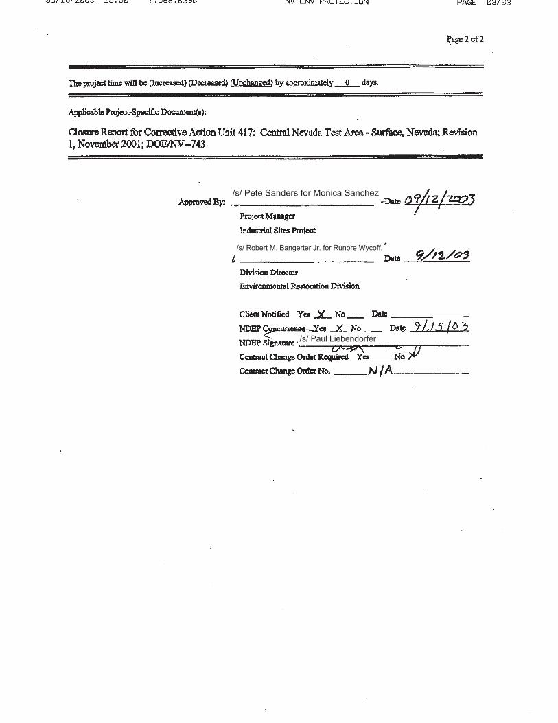
/s/ Pete Sanders for Monica Sanchez
/s/ Robert M. Bangerter Jr. for Runore Wycoff.
/s/ Paul Liebendorfer
National Nuclear Security Administration
Christine Andres, Chief Bureau of Federal Facilities
Department of Energy National Nuclear Security Administration
Nevada Field Office P.O. Box 98518
Las Vegas, NV 89193-8518
JUN s· Z015
Division of Environmental Protection 2030 East Flamingo Road, Suite 230 Las Vegas, NV 89119-0818
SUB MITT AL OF THE RECORD OF TECHNICAL CHANGE (ROTC) NUMBER DOE/NV--743 ROTC 3 FOR THE FINAL CLOSURE REPORT, REVISION 1, FOR CORRECTIVE ACTION UNIT 417: CENTRAL NEV ADA TEST AREA - SURF ACE, NEV ADA, NOVEMBER 2001
Enclosed for your records is one uncontrolled copy of the Record of Technical Change DOE/NV- 743 ROTC 3 for the subject document.
Please direct comments and questions to Mark Kautsky, Office of Legacy Management, at (970) 248-6018.
EMO:l 1306.CD
Enclosures: As stated
cc w/o encl. via e-mail: Mark McLane, NDEP Mark Kautsky, DOE/LM J. T. Fraher, DTRA/CXTS FF ACO Group, NFO NFO Read File
~ obert F. Boehlecke, Manager
Environmental Management Operations

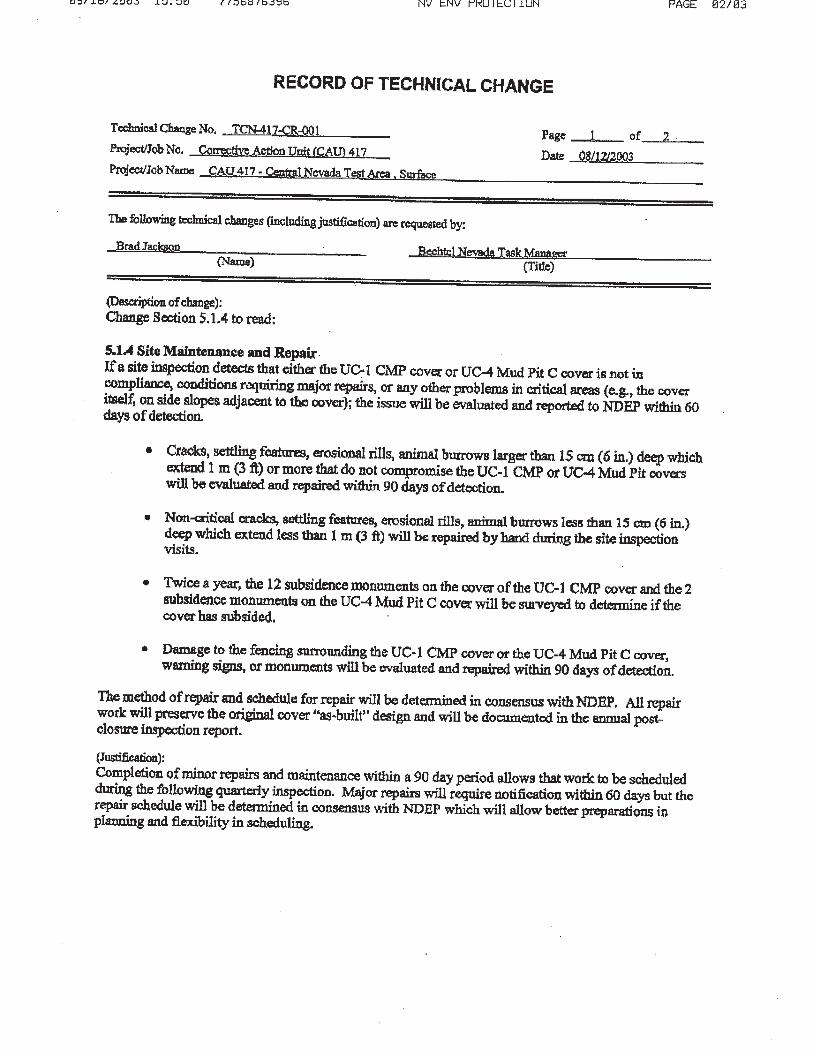
RECORD OF TECHNICAL CHANGE
Technical Change No. OOE/NV--743 ROTC 3 Page of __ _
Activity Name Central Nevada Test Area-ROTC forCAU 417 Closure Report Date April 29. 2015
The following technical changes (including justification) are requested by:
Mark Kauts!cy (Name)
Description of Change:
Site Manager. Deoartment of Energy/Office of Legacy Management (Title)
Page 50, Section 5.1.3, The following sentences shalt be added to the end ofthe first paragraph: As per the February 2015 Path Forward letter (dated February 25, 2015), the following was decided:
• Remove requirements for continued monitoring of soil moisture and subsidence from the UC-1 CMP and UC-4 Mud Pit. (The fences and engineered soil covers provide additional controls that prevent any inadvertent intrusions to the underlying drilling mud; these engineering controls will remain in place.)
• Continue visual inspections at all the sites and provide photographs of selected sites to document the health and stability of the vegetation at the UC- I CMP cover.
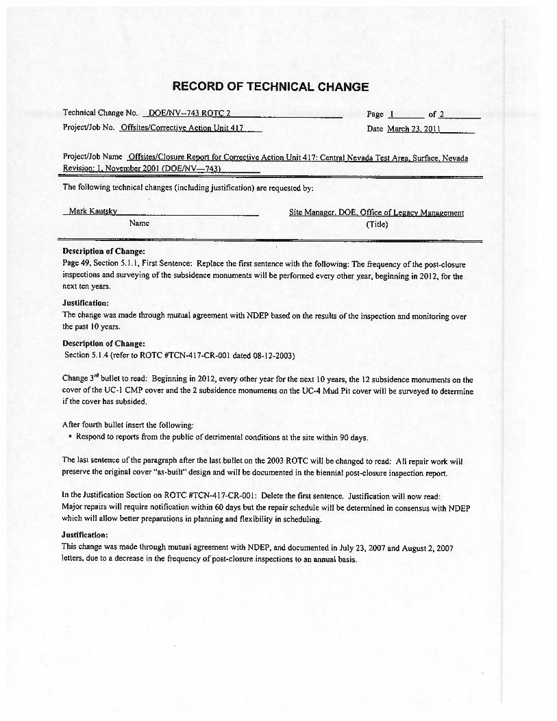
• Prepare a brief report every 2 years to document the inspections. This requirement is in accordance with ROTC OOE/NV-743 ROTC 2 dated March 23, 2011, that changed the reporting schedule to every other year for the next JO years, starting in 2010 (first report in 2012) and ending in 2020.
Justification: The change was made in mutual agreement with NDEP and is based on soil moisture data from the UC-I Central Mud Pit and subsidence data from the UC-1 Central Mud Pit and UC-4 Mud Pit collected over the past 14 years.
The task time will be unchanged.
Applicable Activity-Specific Document(s):
Closure Report for Corrective Action Unit 417: Central Nevada Test Area, Surface, Nevada, Revision: I
Approved By: Date S- t"S-'Zoo 15
Date
II
DISCLAIMER STATEMENT
Reference herein to any specific commercial product, process, or service by trade name,trademark, manufacturer, or otherwise, does not necessarily constitute or imply its endorsement,recommendation, or favoring by the U.S. Government or any agency thereof or its contractors orsubcontractors.
AVAILABILITY STATEMENT
Available for sale to the public from-U.S. Department of CommerceNational Technical Information Service5285 Port Royal RoadSpringfield, VA 22161-0002Telephone: 800.553.6847Fax: 703.605.6900E-mail: [email protected] ordering: http://www.ntis.gov/ordering.htm
Available electronically at http://www.doe.gov/bridge
Available for a processing fee to U.S. Department ofEnergy and its contractors, in paper, fromU.S. Department of EnergyOffice of Scientific and Technical InformationP.O. Box 62Oak Ridge, TN 37831-0062Telephone: 865.576.8401Fax: 865.576.5728E-mail: [email protected]
'III
1
DISCLAIMER Portions of this document may be illegible in electronic image products. Images are produced from the best available original document.
This page intentionally left blank
7)G~tJ U - - J cfJrpO~jNU /117It' SJ)
c6~rj
fJ f3 F 'd/II/0 :L--
JAN I 0 L002
Department of EnergyNational Nuclear Security Administration
Nevada Operations OfficeP.O. Box 98518
Las Vegas, NV 89193-8518
Northern Nevada Public Reading RoomNevada State Library and Archives100 N. Stewart St.Carson City, NV 89701-4285
Southern Nevada Public Reading RoomP.O. Box 98521, MIS NLV 040Las Vegas, NY 89193-8521
SUBMITTAL OF THE FINAL CLOSURE REPORT FOR CORRECTIVE ACTION UNIT 417:CENTRAL NEVADA TEST AREA SURFACE, NEVADA, NOVEMBER 2001
The Federal Facility Agreement and Consent Order (FFACO) requires that the encloseddocument is available to the public through the FFACO Public Reading Rooms. The followingcopies have been provided for submittal into the FFACO Public Reading Room collection inaccordance with the DOEINV Distribution Processfor FFACO Documents.
Southern Nevada Public Reading Room: 1 controlled copy1 uncontrolled copy
Northern Nevada Public Reading Room: 1 uncontrolled copy
Please direct comments and questions to Peter A. Sanders, of my staff, at (702) 295-1037.
ERD:PAS
~£i~'-eZLRunore C. Wycoff, i ctor / CEnvironmental Res ration ivision
Enclosure:As stated
cc wlencl. (controlled):Public Reading Room Coordinator, IT,
Las Vegas, NV
Multiple Addressees
cc wlenel. (uncontrolled):TIRC, NNSAlNV, Las Vegas, NYBN Document Production .. ...(electronic copy to OSTI)
-2- JAN 16 2002
cc wlo end:M. A. DeBurle, NDEP, Carson City, NYEric Shanholtz, DTRA, Mercury, NY
'"""" LTC P. M. Loomis, DTRA, MIS 645, Mercury, NVDTRA Environmental, MIS 645, Mercury, NYBN Technical Information Officer, MIS NLV048, Las Vegas, NYG. M. Romano, IT, Las Vegas, NVK. A. Hoar, ESHD, NNSAlNV, Las Vegas, NVJ. M. Ford, OPAl, NNSAlNV, Las Vegas, NYP. L. Hall, EM, NNSAlNV, Las Vegas, NVP. A. Sanders, ERD, NNSAlNV, Las Vegas, NV
CLOSURE REPORTFOR CORRECTIVE ACTION UNIT 417:
CENTRAL NEVADA TEST AREASURFACE, NEVADA
DOEINV--743
,-
,-Controlled Copy No.:_
.-
Revision 1
November 2001
Prepared for the U.S. Department of EnergyNational Nuclear Security Administration
Nevada Operations Officeunder Contract No. DE-AC08-96NVI1718
GEINTENTIONALLY LEFT BLANK
•
•
..
..
..
...
'."III
wJ
11 ,
••
,..-
-
DOE/NV--743
CLOSURE REPORT FORCORRECTIVE ACTION UNIT 417:CENTRAL NEVADA TEST AREA
SURFACE, NEVADA
_.
Approved by: ----..:+-J.~::==....:::::::::z~~~¥---M nica L Sanchez, Projecto ites Project
APProVedbY~~rEnvironmental Restoration Division
III
Date: L,p,LOl
Date: 1</; I tJ /i

THIS PAGE INTENTIONALLY LEFT BLANK
IV
..•
•
J
..
•
I....
Closure Report - CAU No. 417Central Nevada Test AreaSection: ContentsRevision: IDate: November 5. 2001
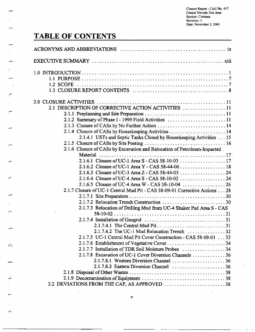
TABLE OF CONTENTS
ACRONYMS AND ABBREVIATIONS IX
EXECUTNE SUMMARY xiii
1.0 IN"TRODUCTION 11.1 PURPOSE 71.2 SCOPE 71.3 CLOSURE REPORT CONTENTS 8
2.0 CLOSURE ACTNITIES 112.1 DESCRIPTION OF CORRECTIVE ACTION ACTIVITIES 11
2.1.1 Preplanning and Site Preparation 112.1.2 Summary ofPhase 1- 1999 Field Activities 112.1.3 Closure ofCASs by No Further Action 142.1.4 Closure of CASs by Housekeeping Activities 14
2.1.4.1 USTs and Septic Tanks Closed by Housekeeping Activities 152.1.5 Closure of CASs by Site Posting 162.1.6 Closure of CASs by Excavation and Relocation ofPetroleum-Impacted
Material 172.1.6.1 Closure ofUC-1 Area S - CAS 58-10-03 172.1.6.2 Closure ofUC-1 Area Y - CAS 58-44-06 182.1.6.3 Closure ofUC-3 Area Z - CAS 58-44-03 242.1.6.4 Closure ofUC-4 Area S - CAS 58-10-02 242.1.6.5 Closure ofUC-4 Area W - CAS 58-10-04 26
2.1.7 Closure ofUC-1 Central Mud Pit - CAS 58-09-01 Corrective Actions 282.1.7.1 Site Preparation 302.1.7.2 Relocation Trench Construction 302.1.7.3 Relocation ofDrilling Mud from UC-4 Shaker Pad Area S - CAS
58-10-02 312.1.7.4 Installation of Geogrid 31
2.1.7.4.1 The Central Mud Pit 312.1.7.4.2 The UC-l Mud Relocation Trench 32
2.1.7.5 UC-1 Central Mud Pit Cover Construction - CAS 58-09-01 322.1.7.6 Establishment ofVegetative Cover 342.1.7.7 Installation ofTDR Soil Moisture Probes 342.1.7.8 ExcavationofUC-1 Cover Diversion Channels 36
2.1.7.8.1 Western Diversion Channel 362.1.7.8.2 Eastern Diversion Channel 36
2.1.8 Disposal of Other Wastes 382.1.9 Decontamination ofEquipment 38
2.2 DEVIATIONS FROM THE CAP, AS APPROVED 38
v
-------..__.... --------------
Closure Report- CAU No. 417Central Nevada Test AreaSection: ContentsRevision: IDate: November 5. 2001
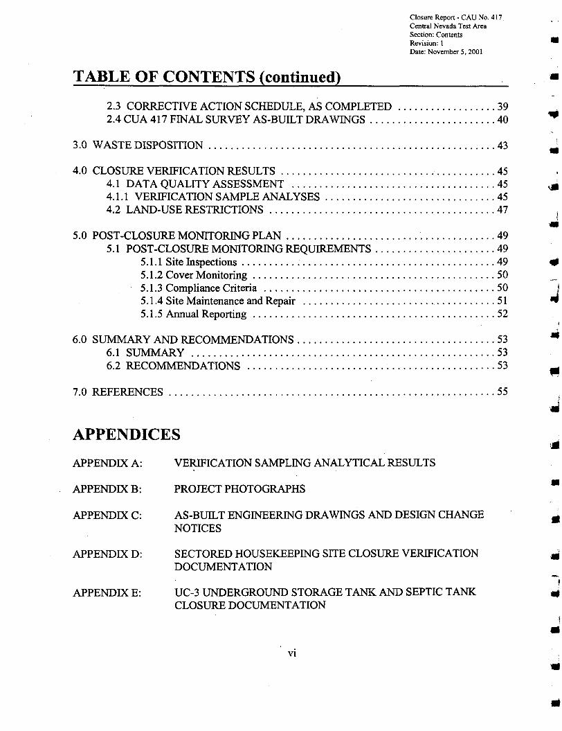
TABLE OF CONTENTS (continued)
2.3 CORRECTIVE ACTION SCHEDULE, AS COMPLETED 392.4 CUA 417 FINAL SURVEY AS-BUILT DRAWINGS 40
3.0 WASTE DISPOSITION 43
4.0 CLOSURE VERIFICATION RESULTS 454.1 DATA QUALITY ASSESSMENT 454.1.1 VERIFICATION SAMPLE ANALYSES 454.2 LAND-USE RESTRICTIONS 47
5.0 POST-CLOSURE MONITORING PLAN 495.1 POST-CLOSURE MONITORING REQUIREMENTS 49
5.1.1 Site Inspections 495.1.2 Cover Monitoring 505.1.3 Compliance Criteria 505.1.4 Site Maintenance and Repair 5I5.1.5 Annual Reporting 52
6.0 SUMMARY AND RECOMMENDATIONS 536.1 SUMMARY 536.2 RECOMMENDATIONS , .. 53
7.0 REFERENCES 55
APPENDICES
•
•
•
•
•
•
APPENDIX A:
APPENDIXB:
APPENDIXC:
APPENDIXD:
APPENDIXE:
VERIFICATION SAMPLING ANALYTICAL RESULTS
PROJECT PHOTOGRAPHS
AS-BUILT ENGINEERING DRAWINGS AND DESIGN CHANGENOTICES
SECTORED HOUSEKEEPING SITE CLOSURE VERIFICATIONDOCUMENTATION
UC-3 UNDERGROUND STORAGE TANK AND SEPTIC TANKCLOSURE DOCUMENTATION
VI
••
-,..I
•
•
Closure Report - CAU No. 417Central Nevada Test AreaSection: ContentsRevision: IDate: November 5, 2001
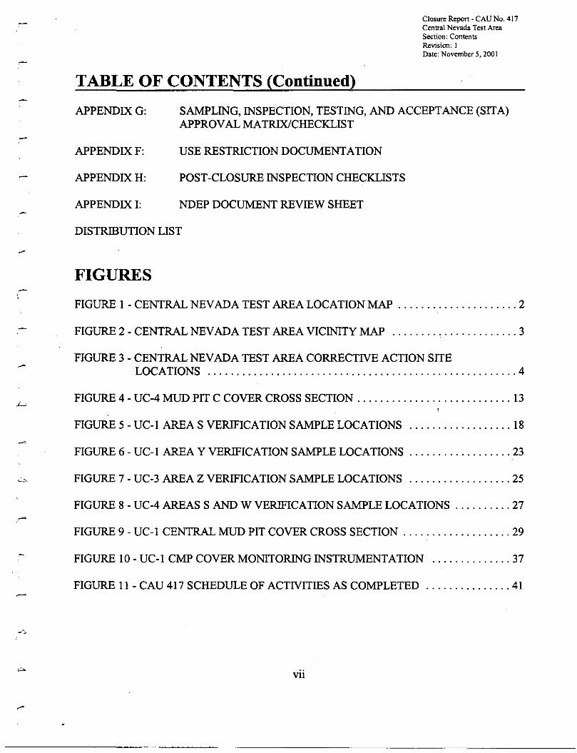
TABLE OF CONTENTS (Continued)
APPENDIXG:
APPENDIXF:
APPENDIXH:
APPENDIX I:
SAMPLING, INSPECTION, TESTING, AND ACCEPTANCE (SITA)APPROVAL MATRIX/CHECKLIST
USE RESTRICTION DOCUMENTATION
POST-CLOSURE INSPECTION CHECKLISTS
NDEP DOCUMENT REVIEW SHEET
-
-":::..
DISTRIBUTION LIST
FIGURES
FIGURE 1 - CENTRAL NEVADA TEST AREA LOCATION MAP 2
FIGURE 2 - CENTRAL NEVADA TEST AREA VICINITY MAP 3
FIGURE 3 - CENTRAL NEVADA TEST AREA CORRECTIVE ACTION SITELOCATIONS 4
FIGURE 4 - UC-4 MUD PIT C COVER CROSS SECTION 13
FIGURE 5 - UC-l AREA S VERIFICATION SAMPLE LOCATIONS 18
FIGURE 6 - UC-l AREA Y VERIFICATION SAMPLE LOCATIONS 23
FIGURE 7 - UC-3 AREA Z VERIFICATION SAMPLE LOCATIONS 25
FIGURE 8 - UC-4 AREAS SAND W VERIFICATION SAMPLE LOCATIONS 27
FIGURE 9 - UC-l CENTRAL MUD PIT COVER CROSS SECTION 29
FIGURE 10 - UC-l CMP COVER MONITORING INSTRUMENTATION 37
FIGURE 11 - CAU 417 SCHEDULE OF ACTIVITIES AS COMPLETED 41
Vll

Closure Report - CAUNo. 417Central Nevada Test AreaSection: ContentsRevision: IDate: November 5. 2001
TABLE OF CONTENTS (Continued)
TABLES
TABLE 1 - SUMMARY OF CLOSURE ACTNITIES 5
TABLE 2 - SUMMARY OF UC-4 MUD PIT C COVER ELEVATION SURVEY DATA ... 14
TABLE 3 - SUMMARY OF ANALYTICAL RESULTS FOR TPH IN VERIFICATIONSAMPLES 20
TABLE 4 - SEED MIXTURE USED ON THE UC-1 CENTRAL MUD PIT COVER 35
TABLE 5 - SUMMARY OF TRANSPLANTS USED ON THE UC-1 MUD PIT COVER ... 36
V1l1
•
•
j!
•
•
•J
••
..
Closure Report - CAU No. 417Central Nevada Test AreaSection: Acr & AbbrRevision: 1Date: November 5, 2001
ACRONYMS AND ABBREVIATIONS
bgs
BLM
BN
CADD
CAP
CAS
CAU
COC
cm
CMP
CNTA
CR
DOE
DOEINV
EPA
ER
FFACO
ft
gal
III
below ground surface
U.S. Bureau ofLand Management
Bechtel Nevada
Corrective Action Decision Document
Corrective Action Plan
Corrective Action Site
Corrective Action Unit
Constituents of Concern
centimeter
Central Mud Pit (located at UC-I)
Central Nevada Test Area
Closure Report
U.S. Department of Energy
U.S. Department of Energy, Nevada Operations Office
U.S. Environmental Protection Agency
Environmental Restoration
Federal Facility Agreement and Consent Order
foot / feet
gallon
inch
IX

Closure Report - CAU No. 417Central Nevada Test AreaSection: Acr & AbbrRevision: 1Date: November 5. 2001
ACRONYMS AND ABBREVIATIONS (continued)
•
km
L
LGP
m
mi
mg/kg
mg/L
NAC
NAD
NDEP
NNSA
NNSA/NV
NTS
QA
SITA
TDR
TPH
TTR
kilometer
square kilometer
liter
Low Ground Pressure
meter
cubic meter
mile
square mile
milligram per kilogram
milligram per liter
Nevada Administrative Code
North American Datum - either 1927 or 1983
Nevada Division of Environmental Protection
National Nuclear Security Administration
National Nuclear Security Administration Nevada Operations Office
Nevada Test Site
quality assurance
Sampling, Inspection, Testing, and Acceptance
time-domain reflectometry
total petroleum hydrocarbons
Tonopah Test Range
x
••
-•
•
[..'II
•
•
•
..
Closure Report- CAU No. 417Central Nevada Test AreaSection: Acr & AbbrRevision: IDate: November 5, 2001
ACRONYMS AND ABBREVIATIONS (continued)
.-
uglkg
ug/L
UTM
UST
microgram perkilogram
microgram per liter
Universal Transverse Mercator
cubic yard
underground storage tank.
Xl
THIS PAGE INTENTIONALLY LEFT BLANK
XlI
I•
•
'.
•
•
•
•t,•
•••
Closure Report - CAU No. 417Central Nevada Test AreaSection: Executive SurmnaryRevision: IDate: November 5, 2001
EXECUTIVE SUMMARY
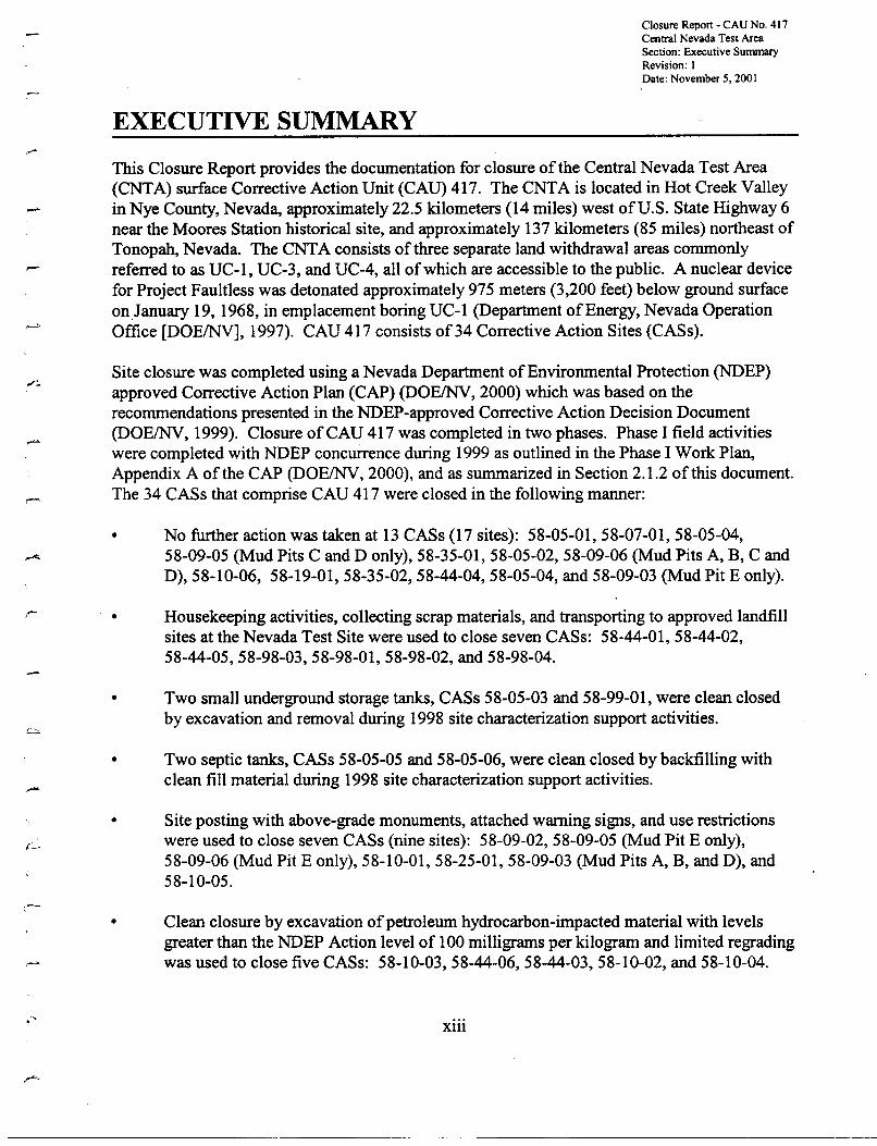
This Closure Report provides the documentation for closure of the Central Nevada Test Area(CNTA) surface Corrective Action Unit (CAD) 417. The CNTA is located in Hot Creek Valleyin Nye County, Nevada, approximately 22.5 kilometers (14 miles) west ofU.S. State Highway 6near the Moores Station historical site, and approximately 137 kilometers (85 miles) northeast ofTonopah, Nevada. The CNTA consists of three separate land withdrawal areas commonlyreferred to as UC-l, UC-3, and UC-4, all ofwhich are accessible to the public. A nuclear devicefor Project Faultless was detonated approximately 975 meters (3,200 feet) below ground surfaceonJanuary 19, 1968, in emplacement boring UC-l (Department of Energy, Nevada OperationOffice [DOEINV], 1997). CAU 417 consists of34 Corrective Action Sites (CASs).
Site closure was completed using a Nevada Department ofEnvironmental Protection (NDEP)approved Corrective Action Plan (CAP) (DOEINV, 2000) which was based on therecommendations presented in the NDEP-approved Corrective Action Decision Document(DOEINV, 1999). Closure of CAU 417 was completed in two phases. Phase I field activitieswere completed with NDEP concurrence during 1999 as outlined in the Phase I Work Plan,Appendix A of the CAP (DOEINV, 2000), and as summarized in Section 2.1.2 of this document.The 34 CASs that comprise CAD 417 were closed in the following manner:
• No further action was taken at 13 CASs (17 sites): 58-05-01,58-07-01,58-05-04,58-09-05 (Mud Pits C and D only), 58-35-01, 58-05-02, 58-09-06 (Mud Pits A, B, C andD),58-1O-06, 58-19-01,58-35-02,58-44-04,58-05-04, and 58-09-03 (Mud Pit E only).
r- •
•
•
•
•
Housekeeping activities, collecting scrap materials, and transporting to approved landfillsites at the Nevada Test Site were used to close seven CASs: 58-44-01,58-44-02,58-44-05, 58-98-03, 58-98-01, 58-98-02, and 58-98-04.
Two small underground storage tanks, CASs 58-05-03 and 58-99-01, were clean closedby excavation and removal during 1998 site characterization support activities.
Two septic tanks, CASs 58-05-05 and 58-05-06, were clean closed by backfilling withclean fill material during 1998 site characterization support activities.
Site posting with above-grade monuments, attached warning signs, and use restrictionswere used to close seven CASs (nine sites): 58-09-02,58-09-05 (Mud Pit E only),58-09-06 (Mud Pit E only), 58-10-01, 58-25-01, 58-09-03 (Mud Pits A, B, and D), and58-10-05.
Clean closure by excavation ofpetroleum hydrocarbon-impacted material with levelsgreater than the NDEP Action level of 100 milligrams per kilogram and limited regradingwas used to close five CASs: 58-10-03,58-44-06,58-44-03,58-10-02, and 58-10-04.
Xlll
•
Closure Report - CAU No. 417Central Nevada Test AreaSection: Executive SummaryRevision: IDate: November 5, 2001
Construction of two engineered covers was used to close CASs 58-09-01 (UC-1 CentralMud Pit) and 58-09-03 (UC-4 Mud Pit C only) in place. The Central Mud Pit cover wasvegetated and instrumented with time-domain reflectometry sensors to monitor soilmoisture in the cover. The UC-4 Mud Pit C cover was a non-vegetated cover system thatused a geosynthetic clay liner to prevent infiltration from reaching the waste package.Following cover construction, a fence was erected around each cover and warning signsposted to prevent damage or intrusion into the covers.
1
•
•....
Because CAU 417 has been closed by following the approved CAP (DOE/NV, 2000) the NNSArequests the CAU 417 be promoted from Appendix ill to Appendix VI "Closed CorrectiveAction Units" of the Federal Facility Agreement and Consent Order (FFACO, 1996).
XIV
•-•
-.
•
•
III
•
•
..•
--
Closure Report - CAU No. 417Central Nevada Test AreaSection: IntroductionRevision: IDate: November 5, 2001
1.0 INTRODUCTION
This Closure Report (CR) provides documentation for the closure of the Central Nevada TestArea (CNTA) surface, Corrective Action Unit (CAD) 417, in accordance with the FederalFacility Agreement and Consent Order (FFACO) (FFACO, 1996).
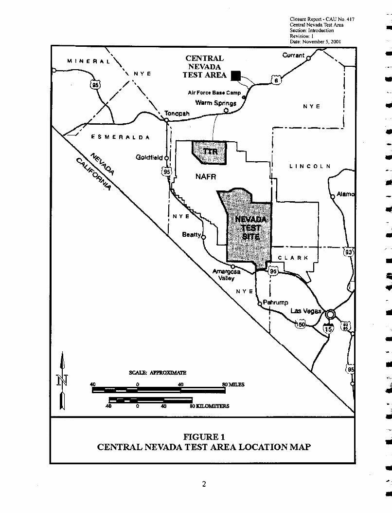
The CNTA is located in Hot Creek Valley, Nye County, Nevada, approximately 22.5 kilometers(Ian) (14 miles [mil) west ofU.S. State Highway 6, approximately 55 km (34 mi) north ofWannSprings, Nevada, and approximately 135 km (85 mi) northeast of Tonopah, Nevada (Figure 1).CNTA consists of three separate land withdrawal areas commonly referred to as UC-l, UC-3,and UC-4 (Figure 2). The central land withdrawal area, UC-l, spans approximately 2.6 squarekilometers (krrr') (1 square mile [mi2
]). UC-3 and UC-4 span approximately 3.9 km2 (1.5 mf)each. UC-3 and UC-4 are located roughly 4 km (2.5 mi) south and north ofUC-l, respectively.
All three CNTA land withdrawal areas are accessible to the public. The sites were obtained bythe Atomic Energy Commission (presently known as the U.S. Department ofEnergy, NationalNuclear Security Administration [NNSA]) from the U.S. Bureau ofLand Management (BLM).A nuclear device for Project Faultless was detonated approximately 975 meters (m) (3,200 feet[fi]) below the ground surface (bgs) on January 19, 1968, in emplacement boring UC-l(Department of Energy, Nevada Operation Office [DOEINV], 1997). Two other emplacementborings (UC-3 and UC-4) were drilled on this site. These emplacement borings were not usedand were subsequently closed in place in 1974 by the U.S. Atomic Energy Commission.Emplacement holes UC-3 and UC-4 are included in the CNTA subsurface CAU 443.
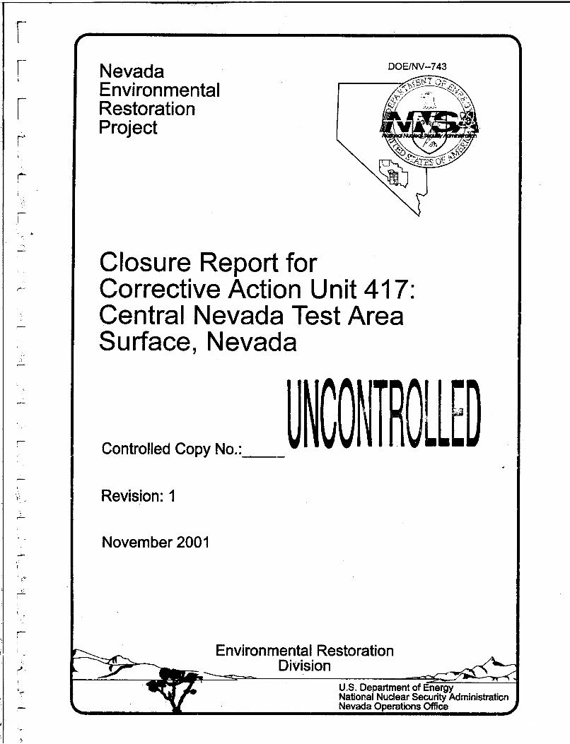
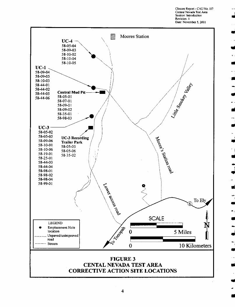
CAU 417 consists of34 Corrective Action Sites (CASs) (Figure 3) as listed in Appendix ill ofthe FFACO (FFACO, 1996». CAU 417 was characterized between September 1996 and June1998 in four separate field investigations. The results of the CAU 417 site investigation showthat the only constituents ofconcern (COC) detected was total petroleum hydrocarbons (TPH) inthe diesel/motor oil range whose concentration exceed the Nevada Administrative Code (NAC)Action level of 100 milligrams per kilogram (mg/kg) (NAC, 1996). The results of the sitecharacterization are presented in Appendix D of the Corrective Action Decision Document(CADD) (DOEINV, 1999). The recommended corrective actions for the 34 CASs are presentedin the CADD for CAD 417 (DOEINV, 1999). The CASs and the corrective actions taken toclose these CASs are shown in Table 1.
1
-
•
...
•
•
I..
.... -,
f
•
•
•..
..NYE
Closure Report- CAU No. 417Central Nevada Test AreaSection: IntroductionRevision: 1Date: November 5, 2001
LINCOLN
I
II
f•
,..---- J•I,
~l
CENTRALNEVADA
TEST AREA
40 8OMn.ESo
o-- -- - ---
40
--------40
..MINERAL"
.., NY E
FIGURElCENTRAL NEVADA TEST AREA LOCATION MAP •
•2
•

Closure Report- CAU No. 117Central Nevada Test AreaSection: IntroductionRevision: IDate: November 5, 2001
LEGEND
Emplacement Holelocation
................. Unpaved/unimprovedroad
---Stream
.....................
(//Wann Springs ~_---I.
~\\ ......""
\:_ Moores Station ·······....
UC-4 - ........\, '.....//
UC-l_ If
(Faultless)---":"I;ji~~, /.</UC-3 .. s... .-, .s'&....
: j' ··"···.~6...·/! ···ro:;
, ! ! \~<"!
h ! ! ...... OqQ' Noname Hill
(f X\ Repeater Site
/---....'-.../ ~ {'-<.. \r ~ .-----J\\ ". i\'\ -, i ~.... <:.:( \\\£ ~\;..! \~
/ J ~ ~/ 1 \) ~ \
/ ,g--< -.~Air Force «\
Base camp \......., \
.•..•...•. \\
..... "
--
Source: AEC, 1973
SCALE
oi
5 Miles
o 10 Kilometers
FIGURE 2CENTRAL NEVADA TEST AREA VICINITY MAP
3
Closure Report - CAU No. 117Central Nevada Test Area ISection: Introduction ..Revision: IDate: November 5, 2001
-
-
•
j
•
•
-J
J•
•..
•
•
...
..
..
........
o
~ Moores StationUC4 \.58-0;-0~ \\58-09-03 '" ',58-10-02 •. \,.,58-10-04 -.58 10-05 \
-..J
Central Mud ~t .. //I:~58-05-01 /! ....\58-07-01 .../! \'"58-09-01 .... I -,58-09-02 /..... / .58-35-01 ...... / .
~ (("'/"-- ,~~~~02 /! I "'\////58-05-05 UC-3 Recording./ ) \" ~58-09-06 Trailer Park ! / \. 0
58-10-01 58-05-03 !, \... %~58-10-06 58-05-06 ! \. rP
58-19-01 58-35-02 ! i! ..., ~58-25-01 : v \ ~.
58-44-03 i \ ~
58-44-04 ·\/'--..1..../ \ '058-98-01 \ ~ .58-98-02 \58-98-04 ~ I \" \58-99-01 ~) \\\ 0 I
{ \, " ~2: -,\ ~
-, ........ 0
....\ •.•...•~<,
UC-l58-09-0458-09-0558-10-0358-44-0158-44-0258-44-0558-44-06
LEGEND• Emplacement Hole
location...............Unpaved/unimproved
road--_._- Stream
FIGURE 3CENTAL NEVADA TEST AREA
CORRECTIVE ACTION SITE LOCATIONS••
4 •
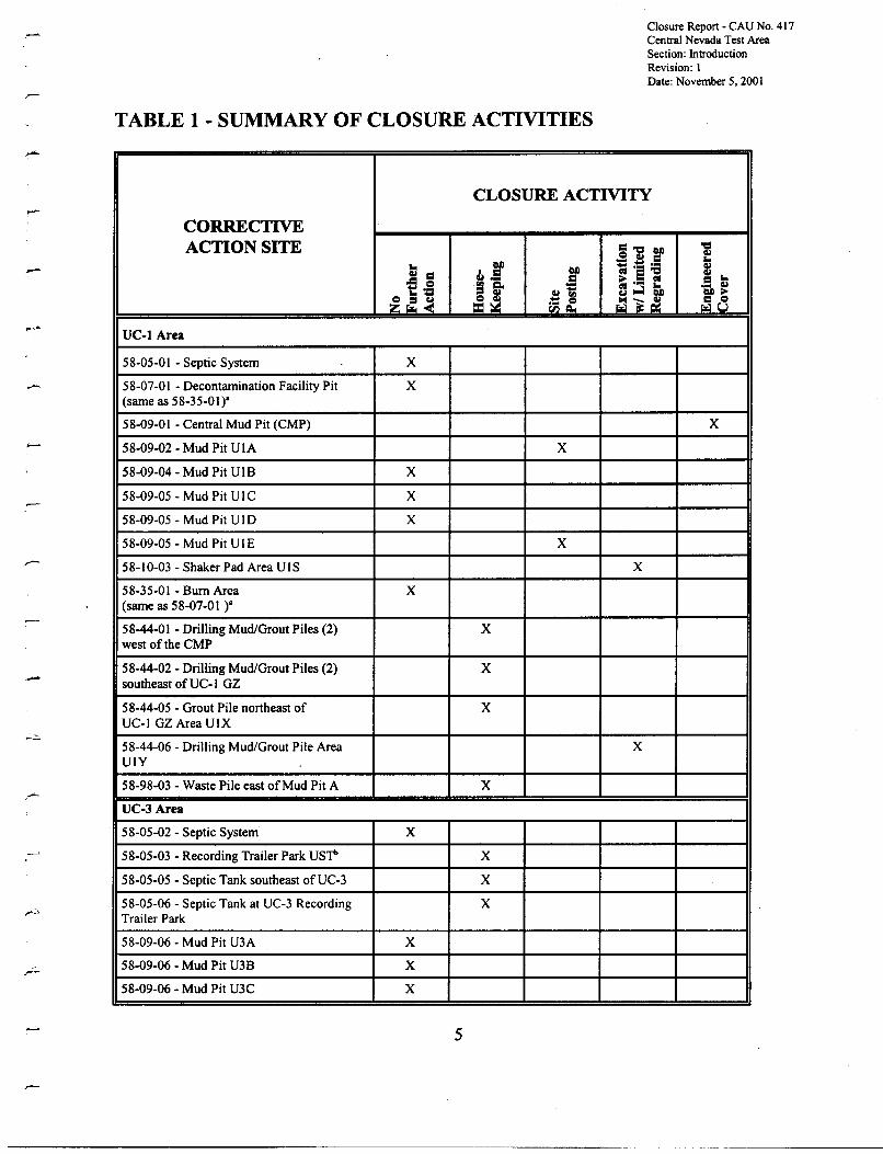
TABLE 1 - SUMMARY OF CLOSURE ACTIVITIES
Closure Report - CAU No. 417Central Nevada Test AreaSection: IntroductionRevision: IDate: November 5, 2001
-
-
CLOSURE ACTIVITY
CORRECTIVEACTION SITE ="C:l CAl "C:l
G.lCl G.l = '"''"' CAl := - .•
~ '"'CAl ct ·s "C:lG.l = ~.e =-= Cl
~ •• ctrg c. := ::3~ Q •• G.l1:::=~~
G.l II) CAl~
~~~ ~~ ~"i~ r:i8UC-l Area
58-05-01 - Septic System X
58-07-01 - Decontamination Facility Pit X(same as 58-35-01)'
58-09-01 - Central Mud Pit (CMP) X
58-09-02 - Mud Pit UIA X
58-09-04 - Mud Pit UIB X
58-09-05 - Mud Pit U IC X
58-09-05 - Mud Pit UID X
58-09-05 - Mud Pit UIE X
58-10-03 - Shaker Pad Area UIS X
58-35-01 - Bum Area X(same as 58-07-01 )'
58-44-01 - Drilling Mud/Grout Piles (2) Xwest of the CMP
58-44-02 - Drilling Mud/Grout Piles (2) Xsoutheast of UC-I GZ
58-44-05 - Grout Pile northeast of XUC-I GZ Area UIX
58-44-06 - Drilling Mud/Grout Pile Area XUIY
58-98-03 - Waste Pile east of Mud Pit A X
UC-3 Area
58-05-02 - Septic System X
58-05-03 - Recording Trailer Park usr- X
58-05-05 - Septic Tank southeast ofUC-3 X
58-05-06 - Septic Tank at UC-3 Recording XTrailer Park
58-09-06 - Mud Pit U3A X
58-09-06 - Mud Pit U3B X
58-09-06 - Mud Pit U3C X
5

Closure Report - CAU No. 417Central Nevada Test AreaSection: IntroductionRevision: 1Date: November 5. 2001
TABLE 1 - SUMMARY OF CLOSURE ACTIVITIES (Continued)
CLOSURE ACTIVITY
CORRECTIVEACTION SITE =~ CI)
~
~ ~.E:Ql
CI)...... Ql
Ql = I = CI) =·s -e ~ ....= e Ql •• = ;. .• ='" C. QJ~ 5 ...;l 5i> •• Ql1:::~~
CI);'
~r:~.. '"
~~~ ~8riilf58-09-06 - Mud Pit U3D X
58-09-06 - Mud Pit U3E X
58-10-01 - Shaker Pad Area U3S X
58-10-06 - Drill Mud/Cuttings Area U3X X
58-19-01 - Scrap & Trash Dump" X
58-25-01 - Area E Spill Southern Outlier X
58-35-02 - Burn Area X
58-44-03 - Drill Mud/Grout Spill Area U3Z X
58-44-04 - Drill Mud/Grout Spill Area U3Y X
58-98-01 - Waste Pile west ofUC-3 X
58-98-02 - Waste Pile south of UC-3 X
58-98-04 - Waste Pile southeast ofUC-3 X
58-99-01 - UC3 UST southeast ofUC-3 X
UC-4Area
58-05-04 - Septic System X
58-09-03 - Mud Pit U4A X
58-09-03 - Mud Pit U4B X
58-09-03 - Mud Pit U4C X
58-09-03 - Mud Pit U4D X
58-09-03 - Mud Pit U4E X
58-10-02 - Shaker Pad Area U4S X
58-10-04 - Shaker Pad Area U4W X
58-10-05 - Shaker Pad Area U4X X
Not Assigned - Scrap & Trash Dump east of XUC-4
•The decontamination facility pit and "burn area" were originally identified as two separate sites. However, it was laterdetermined that what was thought to be the burned material was actually part of the asphalt-covered deeon pit liner.
b Underground Storage Tank• As stated in the NDEP-approved CADD (DOEINV, 1999), this CAS was never located in the field and therefore was not
closed by housekeeping activities.
6
,..
•'.
..•..-
•
•...
••••
--"
Closure Report - CAU No. 417Central Nevada Test AreaSection: IntroductionRevision: IDate: November 5. 2001
1.1 PURPOSE
The purpose ofthis document is to:
• Document the closure activities as proposed in the Corrective Action Plan (CAP) forCAD 417 (DOEINV, 2000).
• Obtain a Notice ofCompletion from the NDEP.
• Recommend the movement of CAU 417 from Appendix ill to Appendix IV of theFFACO.
1.2 SCOPE
The following closure activities were implemented for CAU 417:
• No further action was taken at CASs: 58-05-01,58-07-01,58-09-04,58-09-05 (Mud PitsC and D), 58-35-01, 58-05-02, 58-09-06 (Mud Pits A, B, C, and D), 58-10-06,58-19-01,58-35-02, 58-44-04, 58-05-04, and 58-09-03 (Mud Pit E only).
• Housekeeping activities, including removal ofused oil filters, aerosol cans, drums, ironscrap and piping, and grout/mud piles at CAS 58-44-01,58-44-02,58-44-05,58-98-03,58-98-01,58-98-02, and 58-98-04.
• Two small underground storage tanks (USTs), CASs 58-05-03 and 58-99-01, were cleanclosed by housekeeping activities that included excavation and backfilling with clean fillmaterial during 1998 site characterization support activities.
• Two septic tanks, CAS 58-05-05 and 58-05-06, were clean closed by removing the tankcontents (58-05-05 only), and backfilling with clean fill material during 1998 sitecharacterization support activities.
• Site posting, using concrete monuments with attached warning signs, and establishing userestrictions to prohibit intrusive activities for CAS 58-09-02, 58-09-05 (Mud Pit E only),58-09-06 (Mud Pit E only), 58-10-01, 58-25-01, 58-09-03 (Mud Pits A, B, and D) and58-10-05.
• Clean closure ofCASs 58-10-03, 58-44-06, 58-44-03, 58-10-02, and 58-10-04 byexcavating and relocating material with TPH levels above the NDEP Action level of100 mg/kg to the UC-1 Central Mud Pit (CMP) or UC-1 CMP mud relocation trench.Following excavation, each CAS was re-graded to its approximate original groundsurface contours. To encourage the establishment ofnative vegetation, the surface ofeach CAS was scarified to a depth of 0.3 m (1 ft) bgs.
7
Closure Report - CAU No. 417Central Nevada Test AreaSection: Introduction JRevision: IDate: November 5, 2001
•
•
Constructing an engineered cover system over CAS 58-09-01 (UC-l CMP) and CAS58-09-03 (UC-4 Mud Pit C only). Storm water diversion channels and transplantingvegetation were incorporated into the UC-l CMP cover construction. Time-domainreflectometry (TDR) monitoring and data collection instrumentation was installed in theUC-l CMP cover to monitor cover soil moisture content.
Scrap metal unearthed during excavation and recovered during general site housekeepingactivities was transported to the Nevada Test Site (NTS) for reclamation or disposal. Allsanitary trash and debris was disposed of in the Tonopah Test Range (TTR) sanitarylandfill. Approximately 45.4 metric tons (50 tons) of scrap metal and approximately26.5 cubic meters (rrr') (34.7 cubic yards [yd3
]) of sanitary trash were transported off-sitefor disposal.
••
•
••
1.3 .CLOSURE REPORT CONTENTS
This document is divided into the following sections.
••••••••••••••
••
Section 1.0 - Introduction (purpose, scope, contents)Section 2.0 - Closure Activities (description, deviations, schedule, site plan)Section 3.0 - Waste Disposition (wastes encountered and their appropriate disposal)Section 4.0 - Closure Verification Results (laboratory analysis)Section 5.0 - Post-Closure Monitoring PlanSection 6.0 - Summary and RecommendationsSection 7.0 - ReferencesAppendix A - Verification Sampling Analytical ResultsAppendix B - Project PhotographsAppendix C - As-Built Engineering Drawings and Design Change NoticesAppendix D - Sectored Housekeeping Site Closure Verification DocumentationAppendix E - UC-3 Underground Storage Tank and Septic Tank Closure DocumentationAppendix F - Use Restriction DocumentationAppendix G - Sampling, Inspection, Testing, and Acceptance (SITA) Approval Matrix/
ChecklistAppendix H - Post-Closure Inspection ChecklistsAppendix I - NDEP Document Review Sheet
••
-
•......,
•-The following appendices that are listed in the FFACO-approved Closure Report (CR) outlineare not included in this CR: .-••
Closure Certification - Not applicableWaste Disposition Documentation '- Not applicable
8
•
..
..
Closure Report - CAU No. 417Central Nevada Test AreaSection: IntroductionRevision: IDate: November 5, 2001
This report was developed using information and guidance from the following documents:
• Nevada Environmental Restoration Project. Health and Safety Plan, Revision 3,DOEINV, 1998.
• Corrective Action Decision Document for Corrective Action Unit 417: Central NevadaTest Area Surface, Nevada, Revision 1, DOEINV-524, DOEINV, 1999.
• Corrective Action Plan for Corrective Action Unit 417: Central Nevada Test AreaSurface, Nevada, Revision 0, DOEINV-588, DOEINV, 2000.
Construction of the UC-l CMP cover was controlled by the construction drawings and quality-- assurance (QA) requirements developed in the Construction Quality Assurance Plan, Appendix E
ofthe CAP (DOEINV, 2000). The closure of the other CASs that comprise CAU 417 wascontrolled by QA requirements identified in the CAP (DOEINV, 2000). All QA requirementsidentified in the CAP (DOEINV, 2000) were met.
For the five CASs closed by excavation and removal ofhydrocarbon impacted material(Section 2.1.6), no formal data quality objectives were developed. A number of representativesoil verification samples were collected from the excavated areas and analyzed to assure cleanclosure of these sites. All QA requirements identified in the CAP (DOEINV, 2000) for closureofthese CASs were met. In addition, standard laboratory quality assurance/quality controlchecks were made during sample analysis by the contract laboratory. Results ofthese checks areincluded with the sample analytical results in Appendix A of this document.
9
-
THIS PAGE INTENTIONALLY LEFT BLANK
,•--
..••»«,
III
•••~"
•......
Uli
••'"
•-.~..f•
.-.
III.....
10 -..
Closure Report - CAU No. 417Central Nevada Test AreaSection: Closure ActivitiesRevision: 1Date: November 5, 2001
2.0 CLOSURE ACTIVITIES
This section of the CR details the specific corrective action activities implemented andcompleted during the closure ofCAU 417. This section also provides a detailed schedule ofsiteactivities as completed. Photographs showing representative activities during site closure areincluded in Appendix B of this document.
2.1 DESCRIPTION OF CORRECTIVE ACTION ACTIVITIES
The closure of CAU 417 occurred in two phases of field activity. Phase I activities werecompleted in October 1999 and are described in detail in Appendix B of the NDEP-approvedCAP (DOEINV, 2000). Section 2.1.2 of this document also gives a brief summary of the Phase Ifield activities. The Phase II field activities detailed in the CAU 417 CAP (DOEINV, 2000),began in July 2000 and were completed in April 2001, with the majority of activities completedby October 2000. The Phase II field activities are detailed below in Section 2.1.3. In addition,eight CASs (Section 2.1.4) were closed as housekeeping sites in June 1998 during the sitecharacterization field investigation by International Technology Corporation.
Note: For purposes of discussion, CAS closures will be grouped and discussed by closureactivity, rather than geographic location.
2.1.1 Preplanning and Site Preparation
Planning documents prepared prior to beginning CAU 417 closure field activities include theCAP (DOEINV, 2000), Field Management Plan (Bechtel Nevada [BN], 2000a), Site SpecificHealth and Safety Plan (BN, 2000b), a construction work package, a National EnvironmentalPolicy Act Checklist, a State ofNevada Class II Air Quality Operating Permit, Surface AreaDisturbance Permit, a DOEINV Real Estate/Operations Permit, BN Hot Work Permit, and a BNExcavation Permit. A project readiness review meeting was held on May 23, 2000, and a pre-jobbriefing was held in-June 2000.
2.1.2 Summary of Phase I - 1999 Field Activities
With NDEP approval, Phase I field activities were completed at CNTA between June 30 andOctober 15, 1999. Appendix B of the NDEP-approved CAP (DOEINV, 2000) provides adetailed discussion of the 1999 Phase I CNTA field accomplishments. As-built drawings for thePhase I work are included in Appendix C of this document (Drawings T1 - C9). Phase I fieldactivities included the following:
• Installation of a submersible pump in the HTH-2 supply well south ofUC-1. The wellsupplied the water used in soil conditioning for construction work.
11
Closure Report- CAU No. 417Central Nevada Test AreaSection: Closure Activities ~Revision: IDate: November 5.2001
•
•
•
•
•
Construction of two sumps close to the supply well to hold construction water and apipeline from 'the well to the sumps.
Upgrade and repair of site access and haul roads by limited grading.
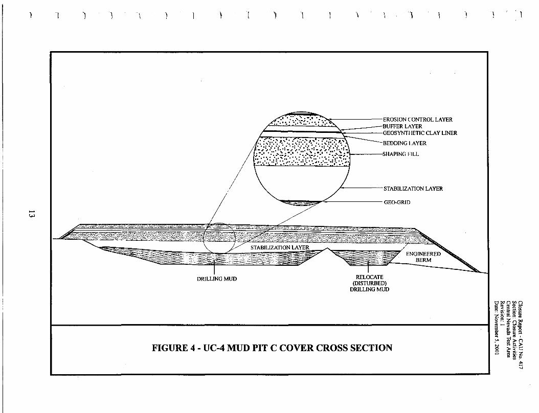
Construction of the UC-4 Mud Pit C cover to prove the cover design and constructionmethods. Figure 4 gives a schematic cross section of the UC-4 Mud Pit C cover asconstructed. Cover construction activities included:- Construction of a mud relocation trench at the east end ofMud Pit C.- Excavation and relocation ofdrilling mud from UC-4 Area S, CAS 58-10-03, to the
relocation trench.- Installation of geogrid material directly over the mud pit and relocation trench.- Placement of a 0.6-m (2-ft) stabilization layer of clean and petroleum
hydrocarbon-impacted material (from UC-I Area S, UC-3 Area Z, and UC-4 Area W)directly on the geogrid.
- Placement of a 0.6-m (2-ft) shaping layer ofclean fill over the stabilization layer.- Placement ofa 15.2-centimeter (em) (6-inch [in]) bedding layer of clean fill over the
shaping layer.- Installation ofa geosynthetic clay liner on the bedding layer.- Placement of a 15.2-cm (6-in) buffer layer over the geosynthetic clay liner.- Placement of a O.3-m (I-ft) erosion control layer over the buffer layer.- Installation ofa cover fence, warning signs, and subsidence monuments.
Excavation of the UC-I CMP mud relocation trench. All excavated material was used inthe UC-4 Mud Pit C cover construction.
Installation ofconcrete above-grade monuments and warning signs at seven CASs(nine sites). Installation of temporary warning signs only at an additional six CASs(seven sites).
j
•
•••
•
••Iii
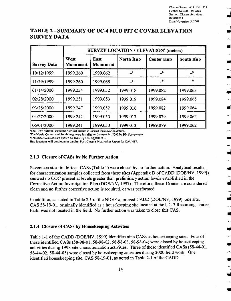
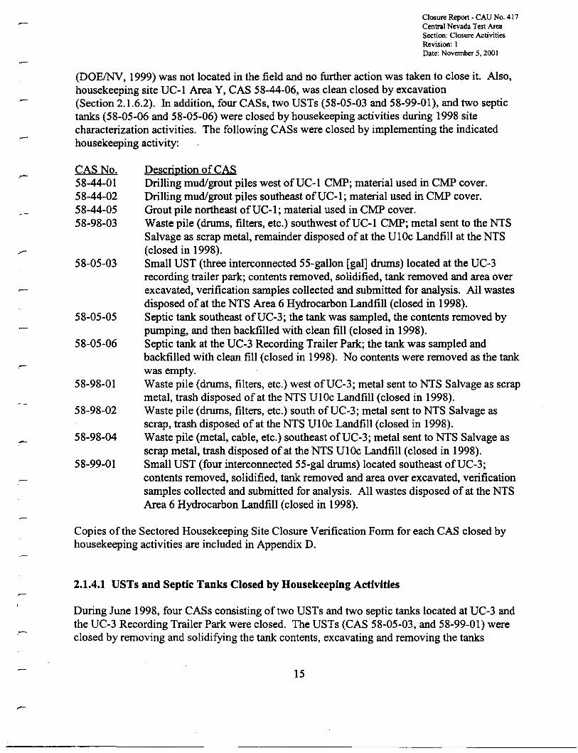
In addition, settlement monitoring of the two subsidence monuments and three elevation hubsplaced by BN survey crew on the UC-4 Mud Pit C was done. Elevation data were collectedmonthly for the first seven months following completion of the UC-4 Mud Pit C cover. The datashow settlement values in agreement with expected calculated values. (See Section 2.1.1.3 ofAppendix A of the CAP [DOEINV, 2000]). Table 2 shows the data collected through June 1,2000. Settlement monitoring will be discussed in more detail in the Post-Closure MonitoringReport to be prepared in 2002. An as-built drawing showing the location of the three additionalsurvey hubs will be included in the 2002 Monitoring report.
--•
12
......
•
) '} ) \ ) } ) l \ \ 1 \ )
w·..:\>.~~;::.:::'~~~:::,·:~:':~t'-:'''':'~it::;.:,~vJ:.~:::''''~~::::·~,r; ~:: :·:;~; :::::··,:~ :-: · , ,:,"t:·: , ·:;"'p ~·: :: ~..:.·:·::.'·....v,::::::
,/
.' . ::-.<:'; ~., '.-.. EROSION CONTROLLAYER......... " ........ • • •• ' •• ' BUFFER LAYER
GEOSYNTHETIC CLAYLINER
.: : .::'.:-~~.-': : ~':'.:.~ ~'.~': : ~':'.:.~ ~.~ BEDDING LAYER'. '",':vr-::', ::'.',,':........: .:'. '0/":", .....::', ::'.
; ~.I .:: .<:.; ~.' .:: .<:.; ~.I .:: »::.;~I-----:SHAPING FILL.~.: .:.:'.,: .:',:: .~.: ~.: .:. :',,:.:',:: .~.:~.: .:.:'.,:::',:: .~.:.~ .:
/ STABILIZATION LAYER
'- ./'::::::JfJ.t;i(~~ GEO-GRID
DRILLING MUD RELOCATE(DISTURBED)
DRILLING MUD
FIGURE 4 - UC-4 MUD PIT C COVER CROSS SECTION
O~Q~!Jfa < ::t n 0~ V;-q =-~
Z --.., 0 ..og-?n< -- Z ()::<l8 ...... ~ [.g... Q.~on .., ::1... ..lA if> ()N -~>g 2;> ~r c::...... n:t. Z
C) ~ ~
~
-.I
'-,
Closure Report - CAU No. 417Central Nevada Test Area 'Section: Closure Activities .JRevision: IDate: November 5, 2001
TABLE 2 - SUMMARY OF UC-4 MUD PIT C COVER ELEVATION •SURVEY DATA
SURVEY LOCATION I ELEVATION8 (meters)
West East North Hub Center Hub South HubSurvey Date Monument Monument
10/12/1999 1999.269 1999.062 b b b
11/29/1999 1999.260 1999.065 b b b
01/14/2000 1999.254 1999.052 1999.018 1999.082 1999.063
02/28/2000 1999.251 1999.053 1999.019 1999.084 1999.065
03/28/2000 1999.247 1999.052 1999.016 1999.082 1999.064
04/27/2000 1999.242 1999.050 1999.013 1999.079 1999.062
06/01/2000 1999.241 1999.050 1999.013 1999.079 1999.062"The 1929 National Geodetic Vertical Datum IS used as the elevation datum."The North, Center, and South hubs were installed on January 14,2000 by BN Survey crew.Monument locations are shown on Drawing C8, Appendix C.Hub locations will be shown in the first Post-Closure Monitoring Report for CAU 417.
2.1.3 Closure of CASs by No Further Action
Seventeen sites in thirteen CASs (Table 1) were closed by no further action. Analytical resultsfor characterization samples collected from these sites (Appendix D ofCADD [DOE/NV, 1999])showed no COC present at levels greater than preliminary action levels established in theCorrective Action Investigation Plan (DOE/NV, 1997). Therefore, these 16 sites are consideredclean and no further corrective action is required, or was performed.
In addition, as stated in Table 2.1 of the NDEP-approved CADD (DOE/NV, 1999), one site,CAS 58-19-01, originally identified as a housekeeping site located at the UC-3 Recording TrailerPark, was not located in the field. No further action was taken to close this CAS.
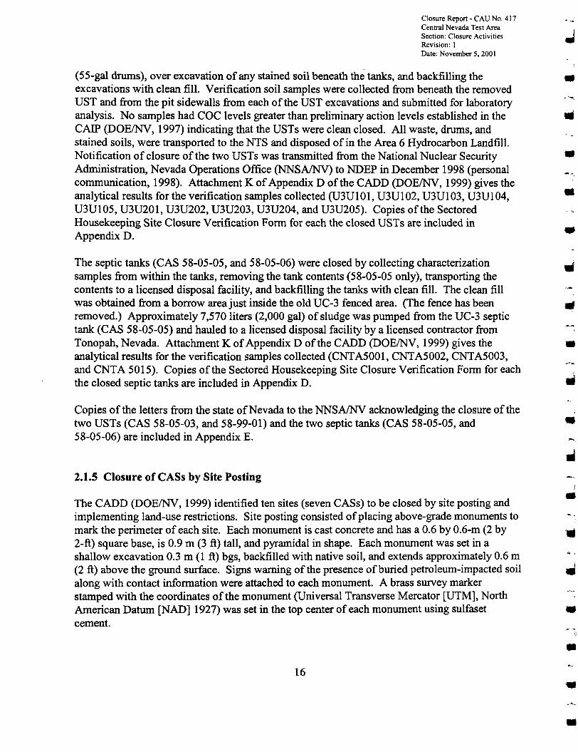
2.1.4 Closure of CASs by Housekeeping Activities
Table 1-1 ofthe CADD (DOE/NV, 1999) identifies nine CASs as housekeeping sites. Four ofthese identified CASs (58-98-01, 58-98-02, 58-98-03, 58-98-04) were closed by housekeepingactivities during 1998 site characterization activities. Three ofthese identified CASs (58-44-01,58-44-02,58-44-05) were closed by housekeeping activities during 2000 field work. Oneidentified housekeeping site, CAS 58-19-01, as noted in Table 2-1 of the CADD
14
..•••
•---,
•
•
•
•
•
Closure Report - CAU No. 417Central Nevada Test AreaSection: Closure ActivitiesRevision: IDate: November S. 2001
(DOEINV, 1999) was not located in the field and no further action was taken to close it. Also,housekeeping site UC-l Area Y, CAS 58-44-06, was clean closed by excavation(Section 2.1.6.2). In addition, four CASs, two USTs (58-05-03 and 58-99-01), and two septictanks (58-05-06 and 58-05-06) were closed by housekeeping activities during 1998 sitecharacterization activities. The following CASs were closed by implementing the indicatedhousekeeping activity:
CAS No.58-44-0158-44-0258-44-0558-98-03
58-05-03
58-05-05
58-05-06
-58-98-01
58-98-02
58-98-04
58-99-01
Description of CASDrilling mud/grout piles west ofUC-l CMP; material used in CMP cover.Drilling mud/grout piles southeast ofUC-I; material used in CMP cover.Grout pile northeast ofUC-l; material used in CMP cover.Waste pile (drums, filters, etc.) southwest ofUC-l CMP; metal sent to the NTSSalvage as scrap metal, remainder disposed of at the Ul Oc Landfill at the NTS(closed in 1998).Small UST (three interconnected 55-gallon [gal] drums) located at the UC-3recording trailer park; contents removed, solidified, tank removed and area overexcavated, verification samples collected and submitted for analysis. All wastesdisposed of at the NTS Area 6 Hydrocarbon Landfill (closed in 1998).Septic tank southeast ofUC-3; the tank was sampled, the contents removed bypumping, and then backfilled with clean fill (closed in 1998).Septic tank at the UC-3 Recording Trailer Park; the tank was sampled andbackfilled with clean fill (closed in 1998). No contents were removed as the tankwas empty.Waste pile (drums, filters, etc.) west ofUC-3; metal sent to NTS Salvage as scrapmetal, trash disposed of at the NTS UI0c Landfill (closed in 1998).Waste pile (drums, filters, etc.) south ofUC-3; metal sent to NTS Salvage asscrap, trash disposed of at the NTS UI0c Landfill (closed in 1998).Waste pile (metal, cable, etc.) southeast ofUC-3; metal sent to NTS Salvage asscrap metal, trash disposed ofat the NTS UI0c Landfill (closed in 1998).Small UST (four interconnected 55-gal drums) located southeast ofUC-3;contents removed, solidified, tank removed and area over excavated, verificationsamples collected and submitted for analysis. All wastes disposed of at the NTSArea 6 Hydrocarbon Landfill (closed in 1998).
--
Copies of the Sectored Housekeeping Site Closure Verification Form for each CAS closed byhousekeeping activities are included in Appendix D.
2.1.4.1 USTs and Septic Tanks Closed by Housekeeping Activities
During June 1998, four CASs consisting of two USTs and two septic tanks located at UC-3 andthe UC-3 Recording Trailer Park were closed. The USTs (CAS 58-05-03, and 58-99-01) wereclosed by removing and solidifying the tank contents, excavating and removing the tanks
15
Closure Report - CAD No. 417Central Nevada Test AreaSection: Closure ActivitiesRevision: IDate: November 5. 2001
(55-gal drums), over excavation of any stained soil beneath the tanks, and backfilling theexcavations with clean fill. Verification soil samples were collected from beneath the removedUST and from the pit sidewalls from each of the UST excavations and submitted for laboratoryanalysis. No samples had COC levels greater than preliminary action levels established in theCAIP (DOEINV, 1997) indicating that the USTs were clean closed. All waste, drums, andstained soils, were transported to the NTS and disposed of in the Area 6 Hydrocarbon Landfill.Notification of closure ofthe two USTs was transmitted from the National Nuclear SecurityAdministration, Nevada Operations Office (NNSAINV) to NDEP in December 1998 (personalcommunication, 1998). Attachment K ofAppendix D of the CADD (DOEINV, 1999) gives theanalytical results for the verification samples collected (U3UI01, U3UI02, U3U103, U3UI04,U3U105, U3U201, U3U202, U3U203, U3U204, and U3U205). Copies of the SectoredHousekeeping Site Closure Verification Form for each the closed USTs are included inAppendix D.
The septic tanks (CAS 58-05-05, and 58-05-06) were closed by collecting characterizationsamples from within the tanks, removing the tank contents (58-05-05 only), transporting thecontents to a licensed disposal facility, and backfilling the tanks with clean fill. The clean fillwas obtained from a borrow area just inside the old UC-3 fenced area. (The fence has beenremoved.) Approximately 7,570 liters (2,000 gal) of sludge was pumped from the UC-3 septictank (CAS 58-05-05) and hauled to a licensed disposal facility by a licensed contractor fromTonopah, Nevada. Attachment K ofAppendix D ofthe CADD (DOEINV, 1999) gives theanalytical results for the verification samples collected (CNTA5001, CNTA5002, CNTA5003,and CNTA 5015). Copies of the Sectored Housekeeping Site Closure Verification Form for eachthe closed septic tanks are included in Appendix D.
Copies of the letters from the state ofNevada to the NNSAINV acknowledging the closure of thetwo USTs (CAS 58-05-03, and 58-99-01) and the two septic tanks (CAS 58-05-05, and58-05-06) are included in Appendix E.
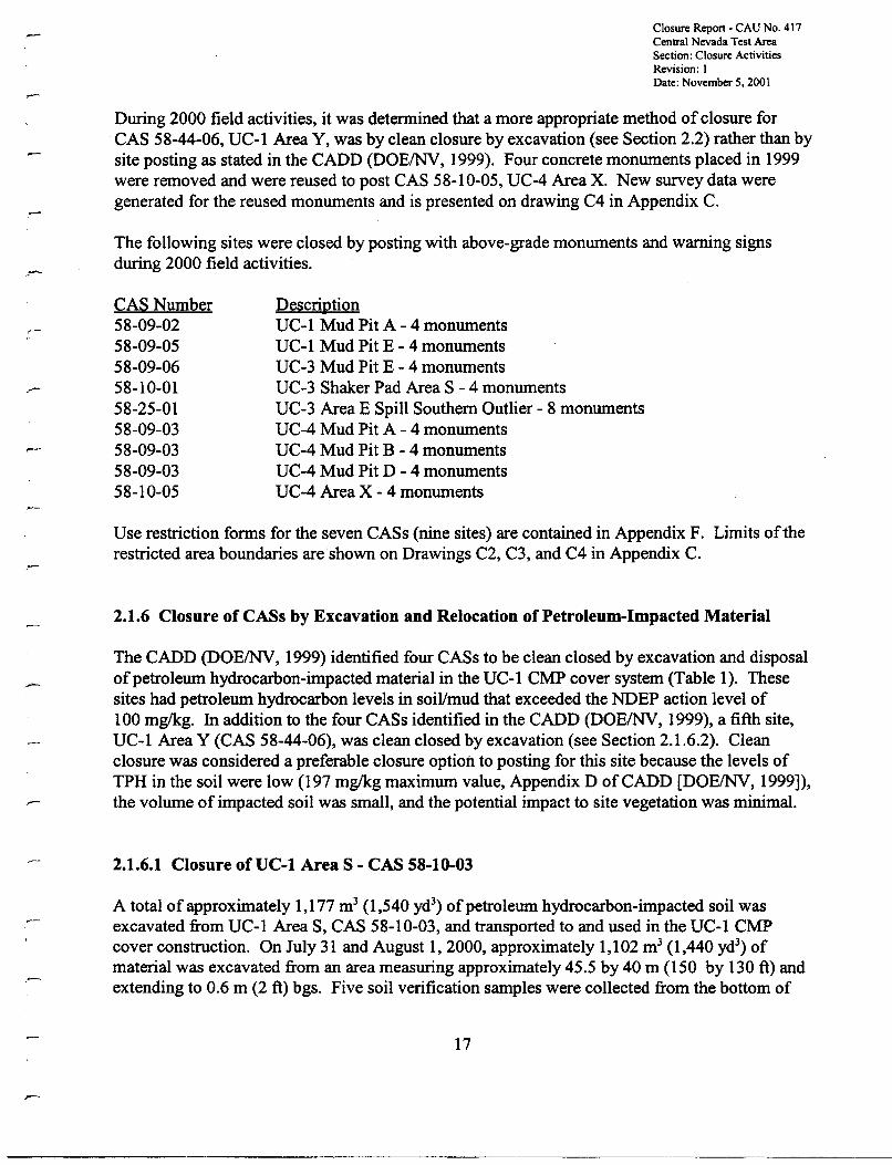
2.1.5 Closure of CASs by Site Posting
The CADD (DOEINV, 1999) identified ten sites (seven CASs) to be closed by site posting andimplementing land-use restrictions. Site posting consisted ofplacing above-grade monuments tomark the perimeter of each site. Each monument is cast concrete and has a 0.6 by 0.6-m (2 by2-ft) square base, is 0.9 m (3 ft) tall, and pyramidal in shape. Each monument was set in ashallow excavation 0.3 m (1 ft) bgs, backfilled with native soil, and extends approximately 0.6 m(2 ft) above the ground surface. Signs warning ofthe presence of buried petroleum-impacted soilalong with contact information were attached to each monument. A brass survey markerstamped with the coordinates of the monument (Universal Transverse Mercator [UTM], NorthAmerican Datum [NAD] 1927) was set in the top center of each monument using sulfasetcement.
16
I
•
•••
•
•
•
••••
Closure Report - CAU No. 417Central Nevada Test AreaSection: Closure ActivitiesRevision: 1Date: November 5, 2001
During 2000 field activities, it was determined that a more appropriate method of closure forCAS 58-44-06, UC-1 Area Y, was by clean closure by excavation (see Section 2.2) rather than bysite posting as stated in the CADD (DOE/NV, 1999). Four concrete monuments placed in 1999were removed and were reused to post CAS 58-10-05, UC-4 Area X. New survey data weregenerated for the reused monuments and is presented on drawing C4 in Appendix C.
The following sites were closed by posting with above-grade monuments and warning signsduring 2000 field activities.
CAS Number58-09-0258-09-0558-09-0658-10-0158-25-0158-09-0358-09-0358-09-0358-10-05
DescriptionUC-l Mud Pit A - 4 monumentsUC-1 Mud Pit E - 4 monumentsUC-3 Mud Pit E - 4 monumentsUC-3 Shaker Pad Area S - 4 monumentsUC-3 Area E Spill Southern Outlier - 8 monumentsUC-4 Mud Pit A - 4 monumentsUC-4 Mud Pit B - 4 monumentsUC-4 Mud Pit D - 4 monumentsUC-4 Area X - 4 monuments
Use restriction forms for the seven CASs (nine sites) are contained in Appendix F. Limits oftherestricted area boundaries are shown on Drawings C2, C3, and C4 in Appendix C.
2.1.6 Closure ofCASs by Excavation and Relocation of Petroleum-Impacted Material
The CADD (DOE/NV, 1999) identified four CASs to be clean closed by excavation and disposalofpetroleum hydrocarbon-impacted material in the UC-l CMP cover system (Table 1). Thesesites had petroleum hydrocarbon levels in soil/mud that exceeded the NDEP action level of100 mglkg. In addition to the four CASs identified in the CADD (DOE/NV, 1999), a fifth site,UC-1 Area Y (CAS 58-44-06), was clean closed by excavation (see Section 2.1.6.2). Cleanclosure was considered a preferable closure option to posting for this site because the levels ofTPH in the soil were low (197 mg/kg maximum value, Appendix D ofCADD [DOE/NV, 1999]),the volume of impacted soil was small, and the potential impact to site vegetation was minimal.
2.1.6.1 Closure ofUC-l Area S - CAS 58-10-03
A total ofapproximately 1,177 m3 (1,540 yd3) ofpetroleum hydrocarbon-impacted soil was
excavated from UC-1 Area S, CAS 58-10-03, and transported to and used in the UC-l CMPcover construction. On July 31 and August 1,2000, approximately 1,102 m3 (1,440 yd') ofmaterial was excavated from an area measuring approximately 45.5 by 40 m (150 by 130 ft) andextending to 0.6 m (2 ft) bgs. Five soil verification samples were collected from the bottom of
17
Closure Report - CAU No. 417Central Nevada Test AreaSection: Closure ActivitiesRevision: IDate: November 5,2001
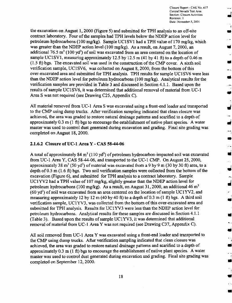
the excavation on August I, 2000 (Figure 5) and submitted for TPH analysis to an off-sitecontract laboratory. Four of the samples had TPH levels below the NDEP action level forpetroleum hydrocarbons (100 mg/kg). Sample UC1SV1 had a TPH value of 170 mg/kg, whichwas greater than the NDEP action level (100 mg/kg). As a result, on August 7, 2000, anadditional 76.5 rrr' (100 yd') of soil was excavated from an area centered on the location ofsample UC1SV1, measuring approximately 12.5 by 12.5 m (41 by41 ft) to a depth of0.46 m(1.5 ft) bgs. The excavated soil was used in the construction of the CMP cover. A sixth soilverification sample, UCISV6, was collected on August 8, 2000, from the bottom of thisover-excavated area and submitted for TPH analysis. TPH results for sample UC1SV6 were lessthan the NDEP action level for petroleum hydrocarbons (100 mg/kg). Analytical results for theverification samples are provided in Table 3 and discussed in Section 4.1.1. Based upon theresults ofsample UC1SV6, it was determined that additional removal ofmaterial from UC-1Area S was not required (see Drawing C25, Appendix C).
All material removed from UC-1 Area S was excavated using a front-end loader and transportedto the CMP using dump trucks. After verification sampling indicated that clean closure wasachieved, the area was graded to restore natural drainage patterns and scarified to a depth ofapproximately 0.3 m (1 ft) bgs to encourage the establishment ofnative plant species. A watermaster was used to control dust generated during excavation and grading. Final site grading wascompleted on August 18, 2000.
2.1.6.2 Closure ofUC-l Area Y - CAS 58-44-06
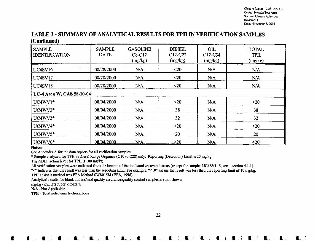
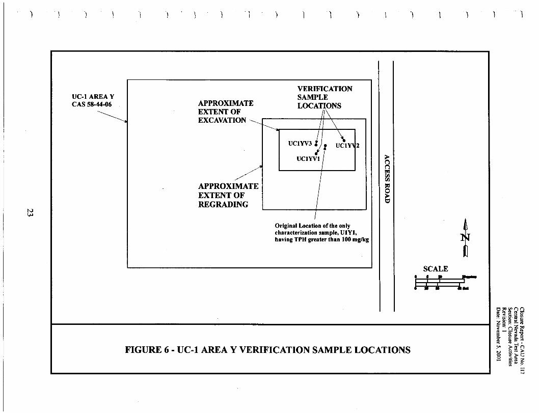
A total of approximately 84 m' (110 yd') of petroleum hydrocarbon-impacted soil was excavatedfrom UC-1 Area Y, CAS 58-44-06, and transported to the UC-1 CMP. On August 25, 2000,approximately 38 rrr' (50 yd") of material was excavated from a 9 by 9 m (30 by 30 ft) area, to adepth of 0.5 m (1.6 ft) bgs. Two soil verification samples were collected from the bottom of theexcavation (Figure 6), and submitted for TPH analysis to a contract laboratory. SampleUC1 YV2 had a TPH value of 107 mg/kg, slightly greater than the NDEP action level forpetroleum hydrocarbons (100 mg/kg). As a result, on August 31, 2000, an additional 46 m'(60 yd') of soil was excavated from an area centered on the location of sample UC1YV2, andmeasuring approximately 12 by 12 m (40 by 40 ft) to a depth of 0.3 m (1 ft) bgs. A third soilverification sample, UC1YV3, was collected from the bottom of this over-excavated area andsubmitted for TPH analysis. Results for DC 1YV3 were less than the NDEP action level forpetroleum hydrocarbons. Analytical results for these samples are discussed in Section 4.1.1(Table 3). Based upon the results of sample UC1YV3, it was determined that additionalremoval ofmaterial from UC-1 Area Y was not required (see Drawing C37, Appendix C).
All soil removed from UC-1 Area Y was excavated using a front-end loader and transported tothe CMP using dump trucks. After verification sampling indicated that clean closure wasachieved, the area was graded to restore natural drainage patterns and scarified to a depth ofapproximately 0.3 m (1 ft) bgs to encourage the establishment ofnative plant species. A watermaster was used to control dust generated during excavation and grading. Final site grading wascompleted on September 12,2000.
18
•
••••
•
i.,--.
i
•II
..•••
ClosureReport - CADNo. 117CentralNevadaTestAreaSection:IntroductionRevision: IDate:November5, 2001
--e - - ..-.-; --•••••
N6431000
N 1200
FIGURE 5 - UC-l AREA S VERIFICATIONSAMPLE LOCATIONS
19

Closure Report - CAU No. 417Central Nevada Test AreaSection: Closure ActivitiesRevision: IDate: November 5, 2001
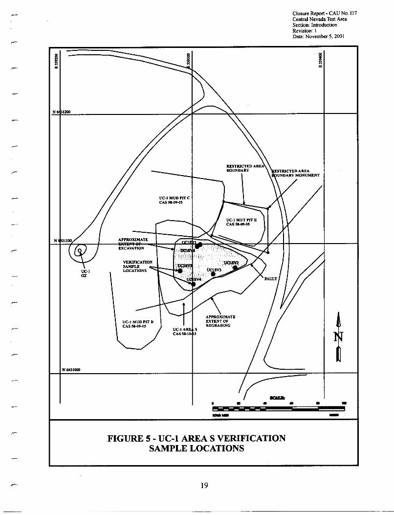
TABLE 3 - SUMMARY OF ANALYTICAL RESULTS FOR TPH IN VERIFICATION SAMPLES
SAMPLE SAMPLE GASOLINE DIESEL OIL TOTALIDENTIFICATION DATE C8-C12 C12-C22 C12-C34 TPH
(mg/kg) (mg/kg) (mg/kg) (mg/kg)
UC-l Area S, CAS 58-10-03
UCISV1* 08/01/2000 N/A 170 N/A 170
UCISV2* 08/01/2000 N/A 41 N/A 41
UCISV3* 08/01/2000 N/A 62 N/A 62
UCISV4* 08/01/2000 N/A 20 N/A 20
UCISV5* 08/01/2000 N/A 24 N/A 24
UCISV6* 08/09/2000 N/A <20 N/A <20
UC-l Area Y, CAS 58-44-06
UCIYVI 08/25/2000 <10 39 <50 39
UCIYV2 08/25/2000 38 <10 69 107
UCIYV3* 08/31/2000 N/A <20 N/A <20
UC-3 Area Z, CAS 58-44-03
UC3ZV1* 08/03/2000 N/A <20 N/A <20
UC3ZV2* 08/03/2000 N/A <20 N/A <20
UC3ZV3* 08/03/2000 N/A <20 N/A <20
UC3ZV4* 08/03/2000 N/A <20 N/A <20
UC3ZV5* 08/03/2000 N/A <20 N/A <20
• • • • .~. L . .I •
20
L j • I ,& .. .. • I ; • I •
'I \,
) 1 \ , ) 1 1 1 1 '} '1 'I Clot 'port - . 'J'Io. 4 I 1\CentralNevadaTest AreaSection: ClosureActivitiesRevision: IDate:November 5, 2001
TABLE 3 - SUMMARY OF ANALYTICAL RESULTS FOR TPH IN VERIFICATION SAMPLESContinued)
SAMPLE SAMPLE GASOLINE DIESEL OIL TOTALIDENTIFICATION DATE C8-C12 C12-C22 C12-C34 TPH
(mg/kg) (mg/kg) (mg/kg) (mg/kg)
UC3ZV6* 08/03/2000 N/A <20 N/A <20
UC-4 Area S, CAS 58-10-02
UC4SV1 08/16/2000 <10 <10 <50 <10
UC4SV2 08/16/2000 <10 31 <50 31
UC4SV3 08/16/2000 <10 <10 <50 <10
UC4SV4 08/16/2000 <10 <10 <50 <10
UC4SV5 08/16/2000 <10 <10 <50 <10
UC4SV6 08/22/2000 <10 <10 80 80
UC4SV7 08/22/2000 <10 <10 <50 <10
UC4SV8 08/22/2000 <10 <10 <50 <10
UC4SV9 08/22/2000 <10 40 86 126
UC4SV10 08/22/2000 <10 <10 <50 <10
UC4SVl1 08/22/2000 <10 <10 64 64
UC4SV12 08/22/2000 <10 22 140 162
UC4SV13 08/22/2000 <10 <10 <50 <10
UC4SV14 08/22/2000 22 43 140 205
lJC4SV1,\ ')R ,~~ ,~~~~ <10 <10 <'\0 <10
21
ClosureReport- CAU No.417CentralNevadaTest AreaSection:ClosureActivitiesRevision: IDate:November 5, 2001
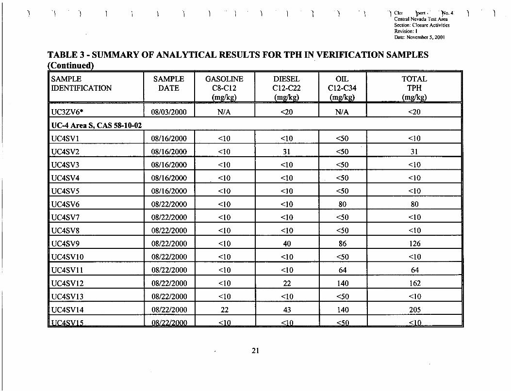
TABLE 3 - SUMMARY OF ANALYTICAL RESULTS FOR TPH IN VERIFICATION SAMPLESContinued)
SAMPLE SAMPLE GASOLINE DIESEL OIL TOTALIDENTIFICATION DATE C8-C12 C12-C22 C12-C34 TPH
(mg/kg) (mg/kg) (mWk~) (mg/kg)
UC4SV16 08/28/2000 N/A <20 N/A N/A
UC4SV17 08/28/2000 N/A <20 N/A N/A
UC4SV18 08/28/2000 N/A <20 N/A N/A
UC-4 Area W, CAS 58-10-04
UC4WVl* 08/04/2000 N/A <20 N/A <20
UC4WV2* 08/04/2000 N/A 38 N/A 38
UC4WV3* 08/04/2000 N/A 32 N/A 32
UC4WV4* 08/04/2000 N/A <20 N/A <20
UC4WV5* 08/04/2000 N/A 20 N/A 20
TTr4WV(l* OR/OAnllllll N/A <20 N/A <20Notes:See AppendixA for the data reports for all verificationsamples.* Sampleanalyzed for TPH in DieselRange Organics (CI0 to C28) only, Reporting (Detection) Limit is 20 mg/kg.The NDEP action level for TPH is 100 mg/kg.All verificationsamples were collected from the bottom of the indicatedexcavated areas (except for samplesUC4SVI -5, see section 4.1.1)"<" indicatesthat the result was less than the reporting limit. For example,"<10" means the result was less than the reporting limit of 10 mg/kg.TPH analysismethod was EPA Method SW8015M (EPA, 1996),Analyticalresults for blank and ms/msdqualityassurance/qualitycontrol samples are not shown,mg/kg - milligramper kilogramN/A - Not ApplicableTPH - Total petroleum hydrocarbons
22
• • "• • •... I &. • a_ • • • • I
) I I ) 1 ) 1 -, )
I
VERIFICATIONSAMPLE
LOCAT,f\NS
I \
ucrvvs 1. i V)"" 2
UCIYVII
APPROXIMATEEXTENT OFEXCAVATION _______
r---... -----++-~-..,
/./1
/APPROXIMATEEXTENT OFREGRADING
UC-l AREA YCAS 58-44-06
~
IOriginal Location of the onlycharacterization sample, UIYl,having TPH greater than 100 mglkg
SCALE• I •
! i If
FIGURE 6 - UC-l AREA Y VERIFICATION SAMPLE LOCATIONS
Closure Report - CAU No. 417Central Nevada Test AreaSection: Closure ActivitiesRevision: IDate: November 5, 2001
2.1.6.3 Closure ofUC-3 Area Z - CAS 58-44-03
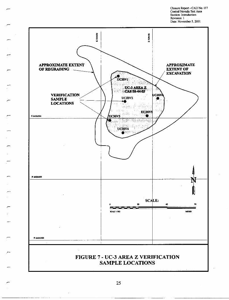
Between July 31 and August 3, 2000, a total of approximately 1,622 m' (2,120 yd') ofhydrocarbon-impacted soil was excavated from UC-3 Area Z, transported to the UC-l CMP, andincorporated into the CMP cover. An area measuring approximately 52 by 52 m (170 by 170 ft)was excavated to an approximate depth of 0.6 m (2 ft) bgs. Six soil verification samples(UC3ZVl through UC3ZV6) were collected from the bottom of the excavated area (Figure 7),and were submitted for TPH analysis to a contract laboratory. TPH levels for all six sampleswere below the NDEP action level for petroleum hydrocarbons (100 mg/kg). Sample analyticalresults are provided in Table 3 and discussed in Section 4.1.1. Based upon the verificationsample results, it was determined that additional removal ofmaterial from UC-3 Area Z was notrequired (see Drawing C26, Appendix C).
All soil removed from UC-3 Area Z was excavated using a front-end loader and transported tothe CMP using dump trucks. After verification sampling indicated that clean closure wasachieved, the area was graded to restore natural drainage patterns and scarified to a depth ofapproximately 0.3 m (1 ft) bgs to encourage the establishment ofnative plant species. A watermaster was used to control dust generated during excavation and grading. Final grading wascompleted on August 17,2000.
2.1.6.4 Closure ofUC-4 Area S - CAS 58-10-02
Between August 2 and 22,2000 approximately 5,872 rrr' (7,680 yd') ofhydrocarbon-impacteddrilling mud was excavated from UC-4 Area S and relocated to the UC-l mud relocation trench.The material was excavated using two front-end loaders and transported to UC-l using dumptrucks. UC-4 Area S spans a small east-west trending drainage located north of the UC-4emplacement hole. Area S has an upper area at the west end ofthe drainage, and a lower area atthe east end of the drainage adjacent to the dirt access road. The upper west excavation measuredapproximately 25 by 70 m (82 by 230 ft) and extended to approximately 2.4 m (8 ft) bgs. Themajority ofmaterial removed was on the south side of the drainage. The lower excavationmeasured approximately 30 by 30 m (98 by 98 ft) and extended to a depth of 1.83 m (6 ft) bgs.The drainage area joining the upper and lower areas was not excavated because no waste materialwas identified as being present during the characterization study (Appendix D of the CADD,[DOE/NV,1999]).
During the 1999 Phase I field activities, approximately 138m3 (180 yd'') of drilling mud materialwas excavated from the lower eastern portion ofArea S and used in the UC-4 Mud Pit C coverconstruction (see Appendix B of CAP [DOE/NV, 2000]). At this time, it was discovered that theupper west portion ofArea S consisted primarily of drilling mud material, and not granular soilmaterial as originally thought. To clean close the area, drilling mud was excavated from both theupper western, and lower eastern portions of the CAS. A total of 18 verification samples werecollected on three different dates from the site and submitted for TPH analysis. Analytical
24
J
•.....•
•
..Ii
j•
•
••
•
APPROXIMATE EXTENTOF REGRADING
VERIFICATIONSAMPLELOCATIONS
N 6416500
N6416400
N 6416300
o
SCN..E 1:7150
SC LE:
Closure Report - CAU No. 117Central Nevada Test AreaSection: IntroductionRevision: IDate: November 5, 2001
APPROXIMATEEXTENT OFEXCAVATION
FIGURE 7 - UC-3 AREA Z VERIFICATIONSAMPLE LOCATIONS
25
Closure Report - CAU No. 417Central Nevada Test AreaSection: Closure ActivitiesRevision: 1Date: November 5, 2001
results for the samples are given in Table 3. Figure 8 shows the area layout and the location ofthe verification samples.
On August 16,2000, five samples (UC4SVI through UC4SV5) were collected from the area,three from the upper area along the southern wall ofthe excavation, and two from the lower areaalong the eastern wall of the excavation. All samples were collected from darkly stained materialdirectly from the walls of the excavation. At the request ofNDEP personnel and in an effort tolimit the extent of the area excavation, these samples were submitted for TPH analysis byfraction to determine if long-chain hydrocarbons were present (personal communication, 2000a).Sample results (Table 3) showed no hydrocarbon fractions in concentrations greater than theNDEP action level for petroleum hydrocarbons (100 mg/kg). These results established thesouthern boundary of the upper area excavation, and the eastern boundary (the dirt access road)of the lower area excavation.
On August 22, 2000, ten verification samples (UC4SV6 through UC4SVI5) were collected fromthe bottom of the upper and lower excavated areas (Figure 8). Samples UC4SV9, UC4SVI2,and UC4SV14 had TPH levels above the NDEP action level for petroleum hydrocarbons(100 mg/kg). As a result, at each of these three verification sample sites, an area measuringapproximately 6 by 6 m (20 by 20 ft) was over excavated to approximately 0.3 m(l ft) bgs and additional verification soil samples were collected. Samples UC4SVI6,UC4SVI7, and UC4SV18 were collected on August 28, 2000, from the bottom of these threeover-excavated areas and submitted for TPH analysis. TPH levels for these three verificationsamples were less than the NDEP action level for petroleum hydrocarbons (100 mg/kg). Theanalytical results are discussed in Section 4.1.1 (Table 5). Based upon the results of samplesUC4SVI6, UC4SVI7, and UC4SVI8, it was determined that additional removal ofmaterialfrom UC-4 Area S was not required (see Drawing C27, Appendix C).
All material removed from UC-4 Area S was placed directly into the UC-I CMP mud relocationtrench and stacked using a front-end loader. After verification sampling indicated that cleanclosure was achieved, the area was graded to restore natural drainage patterns and scarified to adepth of approximately 0.3 m (1 ft) bgs to encourage the establishment ofnative plant species. Awater master was used to control dust generated during excavation and grading. Final gradingwas completed on September 14,2000.
2.1.6.5 Closure ofUC-4 Area W - CAS 58-10-04
j
••..•..
•
•
UC-4 Area W is located in the wash south of the UC-4 Mud Pit C cover access road. On ..August 2 and 3, 2000, a total of approximately 290 m3 (380 yd') ofpetroleum hydrocarbon-impacted soil was excavated from Area W and used in the UC-l CMP cover construction. Anarea measuring approximately 40 by 12 m (140 by 40 ft) was excavated to an approximate depth ..of 0.6 m (2 ft) bgs. Six soil verification samples (UC4WVl through UC4WV6) were collectedfrom the bottom of the excavation on August 4, 2000 (Figure 8), and submitted for TPH analysis.
•26
••
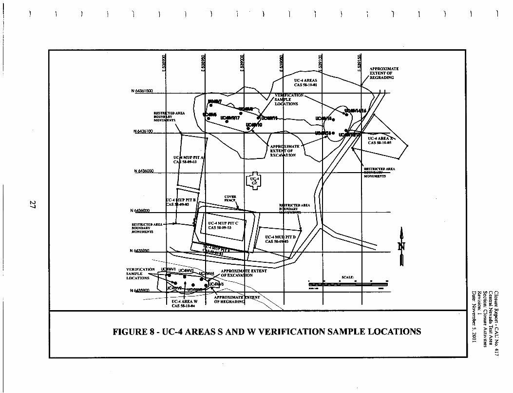
FIGURE 8 - UC-4 AREAS SAND W VERIFICATION SAMPLE LOCATIONS
1
N64361500
N
N
RESTRICTED AREA ......--_...:111IIOUNDARYMONUMENTS
VERIFICATI~Oo::N:::f:1~=:"F:::~:t~~SAMPLELOCATIONS
UC-4AREAWCAS 58-10-04
1
SCALE:
MONUMENTS
Closure Report - CAU No. 417Central Nevada Test AreaSection: Closure ActivitiesRevision: IDate: November 5. 2001
TPH results for the six verification samples were less than the NDEP action level for petroleumhydrocarbons (100 mg/kg). The analytical results are provided in Table 3 and discussed inSection 4.1.1. Based on the sample results, additional removal ofmaterial from UC-4 Area Wwas not required (see Drawing C27, Appendix C).
All soil removed from Area W was excavated using a front-end loader and transported to theCMP using dump trucks. After verification sampling indicated that clean closure was achieved,the area was graded to restore natural drainage patterns and scarified to a depth of approximately0.3 m (1 ft) bgs to encourage the establishment ofnative plant species. A water master was usedto control dust generated during excavation, grading, and scarifying. Final grading wascompleted on August 11, 2000.
2.1.7 Closure ofUC-l Central Mud Pit - CAS 58-09-01 Corrective Actions
The UC-l CMP was closed by constructing an engineered cover over the mud pit. Theconstructed cover system consists of a geogrid placed directly over the drilling mud to supportheavy equipment, covered by a vegetated monolayer cap. Figure 9 shows a schematic crosssection of the constructed cover. As-built drawings for the cover construction are found inAppendix C.
Cover construction activities included the following. The mud relocation trench adjacent to thewestern end ofthe CMP excavated in 1999 was enlarged to hold the additional drilling muddiscovered at UC-4 Area S. An anchor bench was cut around the CMP and geogrid placed on themud surface and anchored to the bench. Once all the mud from UC-4 Area S had been placed inthe mud relocation trench, an anchor bench was cut around the trench and geogrid placed overthe mud and anchored to the bench. The vegetated stabilization layer was constructed by placingtwo 0.6-m (2-ft) lifts of soil over the geogrid. The first 0.6-m (2-ft) lift consists of clean soilfrom the original berms surrounding the CMP and from the excavation of the mud relocationtrench, and hydrocarbon-impacted soil excavated from five CASs that were clean closed (Section2.1.6). Material for the initial 06-m (2-ft) stabilization layer lift was dumped at the edges of theCMP and pushed into placed on the geogrid using Low Ground Pressure (LGP) bulldozers. Thesecond 0.6-m (2-ft) stabilization layer lift consists of clean soil from the CMP berms and theexcavation ofthe flood diversion channels. Clean soil was dumped on the initial lift, and pushedinto place using LGP and D9 bulldozers. The cover was then scarified to a depth of 0.3 m (1 ft)using a motor grader, seeded with native plant species, and mulched with straw to prevent winderosion. Diversion channels to route run-on and run-off away from the cover were excavated tothe west and east of the cover. Twelve subsidence monuments were placed on the cover tomonitor subsidence. A barbed wire and mesh fence was constructed to limit access to the cover.TDR probes and recording instrumentation used to measure the soil moisture in the cover wereplaced at two locations in the cover. In April 2001, approximately 5,000 native plants weretransplanted by hand to the cover. Specific details regarding the cover construction are discussedbelow.
28
I!..I..
..•....
•
..
..~•
..•
..

)
N\0
)
RELOCATE(DISTURBED)
DRILLING MUD
) .) ·1
f-.------DRILLING MUD
l
FIGURE 9 - UC-l CENTRAL MUD PIT COVER CROSS SECTION
tl~QWOa < t:I n 0R -'c; :t. rn
ZS·I!. s Ei::s ....~ .. Z('J'"n_~_n
3 ~ iil 'ggo .. Ei::l..... ~n.
.'" ~>('JN -"'>o i!:" ~.C::= (II a: z
.. .. 0'" .~.....
Closure Report - CAU No. 417Central Nevada Test AreaSection: Closure ActivitiesRevision: 1Date: November 5. 2001
2.1.7.1 Site Preparation
Eight abandoned stand pipes, located in the CMP, measuring approximately 0.9 m (3 ft) indiameter and extending approximately 0.6 m (2 ft) above the surface of the mud, were cut using acutting torch and moved to the scrap metal pile. A "raft" constructed of two 208 L (55 gal)drums and wood planking was moved from the CMP to the scrap/trash pile. Iron pipingimbedded in the northern berm was pulled free from the berm, cut into manageable sized lengths,and moved to the scrap metal pile using a front-end loader. All rocks and debris lager than 15em (6 in) in diameter were removed from the CMP mud surface by hand. The existing barbedwire fence, wood and metal fence posts, and attached warning signs were removed. The bermssurrounding the CMP and the area separating the CMP from the mud relocation trench werecleared ofbrush using a front-end loader. An access path for heavy equipment was cut in theexisting berms. Minor road repairs and improvements were made to the UC-l and UC-4 accessroads using a motor grader. A site command trailer and generator to provide electrical power, aConex box for storage, two-above ground fuel tanks (1,893 and 3,785 L [500 and 1,000 gal]),two portable toilets, a temporary loading dock, and a small brushed area for emergency airvehicles were established as the site command center. An electrical generator to power thesubmersible pump in well HTH-2 was connected and the pipe line from the well head to thesumps was reestablished.
2.1.7.2 Relocation Trench Construction
JI..
1....
•During the 1999 field activities, a trench was excavated adjacent to the UC-l CMP. The trench ..was originally designed to hold an estimated 1,145 nr' (1,500 yd') ofdrilling mud that was to berelocated from UC-4 Area S. During 1999, additional drilling mud material was discovered atthe west end ofUC-4 Area S bringing the approximate total amount ofmud to be excavated and •moved to UC-l to 5,202 m' (6,800 yd"). As a result of the discovery of the additional mud, theUC-l mud relocation trench was expanded during year 2000 field activities. ..
From August 2 to 22, 2000, the UC-l mud relocation trench was expanded from the originaldimensions. The final excavated trench measured approximately 23.5 by 40.7 m (77.1 by ..133.5 ft) at the bottom ofthe trench, and was 6.5 m (21.3 ft) deep on the western bank, and was3.7 m (11.5 ft) deep on the eastern bank. The north and south ends ofthe trench were cut to aslope of 4:1 or shallower to allow access ofheavy equipment. The additional clean soil •excavated from the trench, was used in the CMP cover construction. A bulldozer and twoscrapers were used to excavate the relocation trench. Also, the berm separating the CMP and themud relocation trench was cleared of brush and cut to the designed height and slope angle using a ..bulldozer and scrapper. The bench was sloped to the east to blend the higher mud relocationtrench with the lower CMP (see Drawing C29, C30, and C31 Appendix C).
•30
••
Closure Report - CAU No. 417Central Nevada Test AreaSection: Closure ActivitiesRevision: IDate: November 5, 2001
2.1.7.3 Relocation of Drilling Mud from UC-4 Shaker Pad Area S - CAS 58-10-02
From August 2 to 22, 2000, approximately 5,872 nr' (7,680 yd') ofdrilling mud was excavatedfrom DC-4 Area S, transported to DC-I, and placed in the mud relocation trench adjacent to theCMP. The material was excavated using two front-end loaders and transported using four enddump trucks. The trucks drove into the relocation trench and dumped the drilling mud directlyon to the bottom ofthe trench. The drilling mud was then moved and stacked to the final heightusing a front-end loader.
Once all the drilling mud had been placed in the trench, a geogrid anchor bench was cut aroundthe trench perimeter. The west portion of the anchor bench was cut using a track hoe. The trackhoe was operated from the top of the west bank of the trench to reach down into the trenchapproximately 3 to 4.5 m (10 to 15 ft) and cut the anchor bench. The north and south portions ofthe anchor bench were cut using a front-end loader. The berm separating the relocation trenchand the CMP served as the east side of the anchor bench. This berm was graded to slope to theeast using scrapers, a bulldozer, and a motor grader. This configuration produced a smoothtransition from the higher relocation trench to the lower CMP. The surface of the mud in thetrench was leveled by tamping with the track hoe bucket. Finally, geogrid was placed by handover the surface of the mud in the trench (see Section 2.1.7.4).
2.1.7.4 Installation of Geogrid
2.1.7.4.1 The Central Mud Pit
A geogrid material manufactured by Huesker Inc. (product name Fornit 30 Geogrid) was placeddirectly over the surface ofthe mud in the CMP. The geogrid was a heavy woven plasticmaterial that laterally distributed the weight of the overlying cover soils, supported the heavyequipment used to place soils, and provided a suitable sub-base for the cover. A forklift fittedwith a carpet stinger was used to retrieve rolls of the geogrid from the loading area and tosuspend the roll while the leading edge was advanced by hand across the CMP. Each panel ofgeogrid material was rolled out from the south anchor bench, across the CMP to the north anchorbench, and cut to extend a minimum of 1.5 m (5 ft) onto both anchor benches. Once in place, afront-end loader was used to place a 0.6-m (2-ft) thick anchoring layer ofclean soil on thegeogrid over the anchor bench. The anchoring soil layer was placed from the outside edge ofthegeogrid inward for 3 m (10 ft) around the entire perimeter ofthe CMP. Panels of geogridmaterial were laid in place beginning at the east end of the CMP and progressing to the west endofthe CMP. Edge overlaps of geogrid panels measured a minimum of 1.2 m (4 ft), and endoverlaps of panels measured a' minimum of3 m (10 ft) (Appendix E ofCAP [DOE/NV, 2000]).
rr A total of 40 panels (35 rolls) of geogrid material were used to cover the CMP surface and wereplaced in on July 26, 27, and 28, 2000.
31
._----- _ .•..~---------------------~
Closure Report - CAU No. 417Central Nevada Test AreaSection: Closure ActivitiesRevision: IDate: November 5. 2001
2.1.7.4.2 The UC-l Mud Relocation Trench
Once the mud relocation trench was filled with drilling mud and the surface leveled, geogridmaterial (Fornit 30 Geogrid) was placed by hand directly over the mud surface. Due to thephysical properties of the drilling mud, the cover design specified that two layers of geogrid beused to used to cover the relocated drilling mud to assure that cover soils and the equipmentwould be supported. The first layer ofgeogrid material was placed from the anchor bench on thewest edge of the trench, over the trench, over the berm at the east edge of the trench, andoverlapping onto to CMP geogrid approximately 1.5 m (5 ft). These panels were placedbeginning at the north end of the trench, and ending at the south end ofthe trench. The secondlayer of geogrid was placed in panels running from the south anchor bench to the north anchorbench. This layer was laid in panels beginning at the west side of the trench, and working to theeast anchor bench. Edge overlap for geogrid panels measured a minimum of 1.2 m (4ft), andend overlaps ofpanels measured a minimum of3 m (10 ft) (Appendix E of CAP [DOE/NV,2000]). Twenty-one panels were placed running west to east for the first geogrid layer. Eightpanels were placed running south to north for the second geogrid layer. After the second layer ofgeogrid material was laid out, a front-end loader was used to place a 0.6-m (2-ft) thick anchoringlayer ofclean soil on the geogrid over the anchor benches. The anchoring layer was placed fromthe outside edge ofthe geogrid inward for 3 m (10 ft) around the entire perimeter of the mudrelocation trench. A total of 17 rolls of geogrid was used to cover the relocation trench. Geogridplacement over the mud relocation trench was completed on August 24,2000.
2.1.7.5 UC-l Central Mud Pit Cover Construction - CAS 58-09-01
JJJ
..
•
The UC-1 CMP cover is a vegetated monolayer design that follows the pre-existing contours ofthe CMP. Figure 9 presents a schematic cross section ofthe CMP cover as constructed. Thecover is concave and designed to drain run-off to the cover center and then east offthe coverthrough a cut in the cover berm. Precipitation that infiltrates into the cover is removed from thecover by transpiration by the plants growing on the cover. Construction ofthe CMP cover beganon July 18, 2000, and was completed on September 12,2000. The seeding of the cover wascompleted on October 20, 2000, and the transplanting ofnative species was completed onApril 13,2001. Cover construction activities consisted ofthe following:
••••••••••
Removing piping and debris from the CMP.Cutting an anchor bench around the CMP and mud relocation trench.Installing geogrid material over the drilling mud (Section2.1.7.3).Placing a 1.2-m (4-ft) stabilization layer as two 0.6-m (2-ft) thick lifts over the geogrid.Constructing a fence around the cover.Scarifying and seeding the cover surface.Placing subsidence monuments on the cover.Installing soil moisture monitoring instrumentation.Constructing diversion channels to route run-on and run-off away from the cover.Transplanting native plants onto the cover.
32
..
•••

Closure Report - CAU No. 417Central Nevada Test AreaSection: Closure ActivitiesRevision: 1Date: November 5, 2001
Once the geogrid was installed and anchored in place, work began on placing the first 0.6-m(2-ft) lift of the stabilization layer. The first lift was comprised ofboth clean soil and petroleumhydrocarbon-impacted granular soil. Clean fill was obtained from the excavation of the mudrelocation trench, and from the existing earthen berms surrounding the CMP. Petroleumhydrocarbon-impacted soil was from the clean closure of four CASs, 58-10-03, 58-44-06, 58-4403, and 58-10-04. Both clean soil and hydrocarbon-impacted soil was placed at the edge of theCMP on the geogrid anchoring layer and pushed onto the geogrid using LGP bulldozers. A0.6-m (2-ft) lift of fill was advanced from the edges to the center of the CMP from both the northand south sides of the CMP, always maintaining a minimum of 0.6 m (2 ft) ofmaterial beneaththe LGP bulldozers. Elevation stakes showing a level 0.6 m (2 ft) above the mud surface wereplaced and maintained by a grade checker throughout the CMP. The first lift had a minimumthickness of 0.6 m (2 ft).
The second 0.6-m (2-ft) lift of the stabilization layer was clean soil obtained from the originalberms surrounding the CMP and the excavation of the diversion channels. Clean soil was placednear the edges of the cover and pushed into place using LGP and D9 bulldozers. Elevationstakes showing a level 1.2 m (4 ft) above the mud surface were placed and maintained by a gradechecker throughout the CMP while this lift was placed. This layer was first laid across the centerof the CMP and then advanced toward both the east and west ends of the CMP. The second lifthad a minimum thickness of0.6 m (2 ft). The final surface of the second lift was shaped to thedesigned slope as shown on Drawing C30, Appendix C.
The stabilization layer over the mud relocation trench was constructed of two 0.6-m (2-ft) thicklifts. Both lifts are clean soil from the excavation of the diversion channels. Soil was placed atthe north and south edges of the trench and moved into place using LGP dozers. Thestabilization layer over the berm dividing the CMP and mud relocation trench, was used to blendthe higher finished trench cover surface with the lower finished CMP cover surface as the coverdesign specified (see Appendix C, Drawing C33).
Following the completion ofthe final grading ofthe cover, the entire cover surface was scarifiedto a depth ofapproximately 0.3 m (1 ft) bgs to encourage the establishment ofcover vegetation(see section 2.1.7.6). Twelve subsidence monuments were installed, three over the relocationtrench, and nine on the CMP. The pre-cast concrete monuments measured 0.6 by 0.6 m by15 em (2 by 2 ft by 6 in) thick, and were set 10 em (4 in) below grade in a grout slurry andbackfilled with soil (see Drawing C36). A brass survey pin was set in the center of eachmonument using Sulfaset. Coordinates for each survey pin were stamped onto the pin (seeDrawing C36). Subsidence data (changes in the elevation ofthe subsidence monuments) will beprovided in future CAD 417 Post-Closure Monitoring Reports.
A 1.2-m (4-ft) high four strand barbed wire and chicken wire fence was constructed around theCMP cover area (see Appendix C, Drawing C32). Fence posts were driven into the ground at1.5-m (5-ft) intervals around the cover. Each fence post was driven approximately 0.5 m (1.6 ft)into the ground with approximately 1.2 m (4 ft) ofpost exposed. A grader was used to cut aO.3-m (l-ft) deep "V" shaped trench at the base of the fence line. A 1.2-m (4-ft) lap ofchicken
33
Closure Report - CAD No. 417Central Nevada Test AreaSection: Closure ActivitiesRevision: 1Date:·November 5. 2001
wire mesh was placed at the bottom of this cut and attached to the barbed wire fence. The graderwas used to back fill the cut burying the first 0.3 m (l ft) ofmesh, leaving 0.9 m (3 ft) ofmeshexposed and attached to the wire fence. The mesh fencing is required to prevent animals fromburrowing under the fence and destroying the vegetation. Signs warning ofthe presence ofburied petroleum-impacted soil were attached to the fence at 14 locations (see Appendix C,Drawing C32).
2.1.7.6 Establishment of Vegetative Cover
Vegetation was established on the cover by first preparing the cov:er for seed, seeding the cover,applying mulch to encourage seed germination and provide protection from the wind, and finallytransplanting the year-old native plant species.
The cover was prepared for seeding by scarifying the surface to an approximate depth of 0.3 m(1 ft) bgs. Next, a seed mix ofnative species was broadcast on the cover using a seed drill andharrowed into the cover surface using a drag chain. Straw was then blown over the cover using astraw blower, and crimped into place using a crimping machine. The straw acts as mulch for theseed, provides organic mater, and reduces the potential for erosion of the cover. A total of 105kilograms (231.7 pounds) ofbulk seed mix was applied to the DC-l CMP cover. Table 4 givesthe breakdown of the seed mixture by species and percentage of the total mixture.
During April 2001 approximately 5,200 native transplants were planted on the DC-l CMP cover.The transplants consisted of a mix ofbig sagebrush, fourwing saltbush, rubber rabbitbrush, andDouglas rabbitbrush. All of the plant species are native to the CNTA area. Each transplant wasplaced by hand in a 13-cm (5 in) diameter hole drilled to a depth of 30.5 to 40.6 em (12 to16 in) bgs using a gasoline-powered hand auger. Soil was backfilled and tamped firmly intoplace by hand around the root ball of each transplant. Following planting, each transplantreceived approximately 3.8 L (1 gal) ofwater. Table 5 gives the number and type of plantstransplanted to the CMP cover.
2.1.7.7 Installation of TDR Soil Moisture Probes
After completion of construction and prior to seeding of the CMP cover, a TDR system wasinstalled to monitor soil moisture in the cover. The system consists of 16 TDR sensors, cablingconnecting each sensor to a datalogger which collects the data, a battery and solar panel to powerthe equipment, and a transceiver for remote retrieval of data and access to the dataloggerprograming. The TDR sensors were placed in two pits excavated with a backhoe on the cover.The pits measured approximately 0.9 by 1.8 m (3 by 6 ft), and were dug to a depth ofapproximately 1.4 m (4.5 ft.) below the cover surface, down to the level of the geogrid. In eachpit, two TDR sensors were placed at 0.15, 0.5 0.76, and 1.1 m (0.5, 1.5, 2.5, and 3.5 ft) bgs, oneon each side of the pit. The cables from each sensor were combined and placed into 10-cm
34
•
•
•••
..•
••
••
•
•I
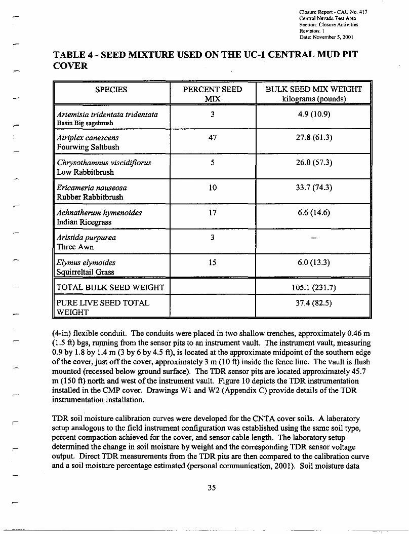
Closure Report- CAU No. 417Central Nevada Test AreaSection: Closure ActivitiesRevision: 1Date: November 5. 2001
TABLE 4 - SEED MIXTURE USED ON THE UC-l CENTRAL MUD PITCOVER
SPECIES PERCENT SEED BULK SEED MIX WEIGHTMIX kilograms (pounds)
Artemisia tridentata tridentata 3 4.9 (10.9)Basin Big sagebrush
Atrip/ex canescens 47 27.8 (61.3)Fourwing Saltbush
Chrysothamnus viscidiflorus 5 26.0 (57.3)Low Rabbitbrush
Ericameria nauseosa 10 33.7 (74.3)Rubber Rabbitbrush
Achnatherum hymenoides 17 6.6 (14.6)Indian Ricegrass
Aristida purpurea 3 --Three Awn
E/ymus e/ymoides 15 6.0 (13.3)Squirreltail Grass
TOTAL BULK SEED WEIGHT 105.1 (231.7)
PURE LIVE SEED TOTAL 37.4 (82.5)WEIGHT
(4-in) flexible conduit. The conduits were placed in two shallow trenches, approximately 0.46 m(1.5 ft) bgs, running from the sensor pits to an instrument vault. The instrument vault, measuring0.9 by 1.8 by 1.4 m (3 by 6 by 4.5 ft), is located at the approximate midpoint of the southern edgeof the cover, just off the cover, approximately 3 m (10 ft) inside the fence line. The vault is flushmounted (recessed below ground surface). The TDR sensor pits are located approximately 45.7m (150 ft) north and west of the instrument vault. Figure 10 depicts the TDR instrumentationinstalled in the CMP cover. Drawings WI and W2 (Appendix C) provide details ofthe TDRinstrumentation installation.
TDR soil moisture calibration curves were developed for the CNTA cover soils. A laboratorysetup analogous to the field instrument configuration was established using the same soil type,percent compaction achieved for the cover, and sensor cable length. The laboratory setupdetermined the change in soil moisture by weight and the corresponding TDR sensor voltageoutput. Direct TDR measurements from the TDR pits are then compared to the calibration curveand a soil moisture percentage estimated (personal communication, 2001). Soil moisture data
35
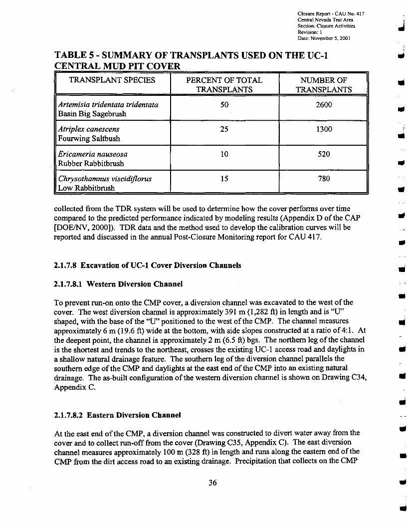
Closure Report - CAD No. 417Central Nevada Test Area JSection: Closure Activities .Revision: IDate: November 5, 2001 .
TABLE 5 - SUMMARY OF TRANSPLANTS USED ON THE UC-l JCENTRAL MUD PIT COVER
TRANSPLANT SPECIES PERCENT OF TOTAL NUMBER OFTRANSPLANTS TRANSPLANTS
Artemisia tridentata tridentata 50 2600Basin Big Sagebrush
Atriplex canescens 25 1300Fourwing Saltbush
Ericameria nauseosa 10 520Rubber Rabbitbrush
Chrysothamnus viscidiflorus 15 780Low Rabbitbrush
collected from the TDR system will be used to determine how the cover performs over timecompared to the predicted performance indicated by modeling results (Appendix D ofthe CAP[DOEINV, 2000]). TDR data and the method used to develop the calibration curves will bereported and discussed in the annual Post-Closure Monitoring report for CAU 417.
2.1.7.8 Excavation ofUC-l Cover Diversion Channels
2.1.7.8.1 Western Diversion Channel
..
If
•To prevent run-on onto the CMP cover, a diversion channel was excavated to the west ofthecover. The west diversion channel is approximately 391 m (1,282 ft) in length and is "U"shaped, with the base of the "U" positioned to the west of the CMP. The channel measures IIIapproximately 6 m (19.6 ft) wide at the bottom, with side slopes constructed at a ratio of4:1. Atthe deepest point, the channel is approximately 2 m (6.5 ft) bgs. The northern leg of the channelis the shortest and trends to the northeast, crosses the existing UC-l access road and daylights in ..a shallow natural drainage feature. The southern leg ofthe diversion channel parallels thesouthern edge of the CMP and daylights at the east end of the CMP into an existing naturaldrainage. The as-built configuration ofthe western diversion channel is shown on Drawing C34, •Appendix C.
2.1.7.8.2 Eastern Diversion Channel
At the east end of the CMP, a diversion channel was constructed to divert water away from thecover and to collect run-off from the cover (Drawing C35, Appendix C). The east diversionchannel measures approximately 100 m (328 ft) in length and runs along the eastern end of theCMP from the dirt access road to an existing drainage. Precipitation that collects on the CMP
36
•
..
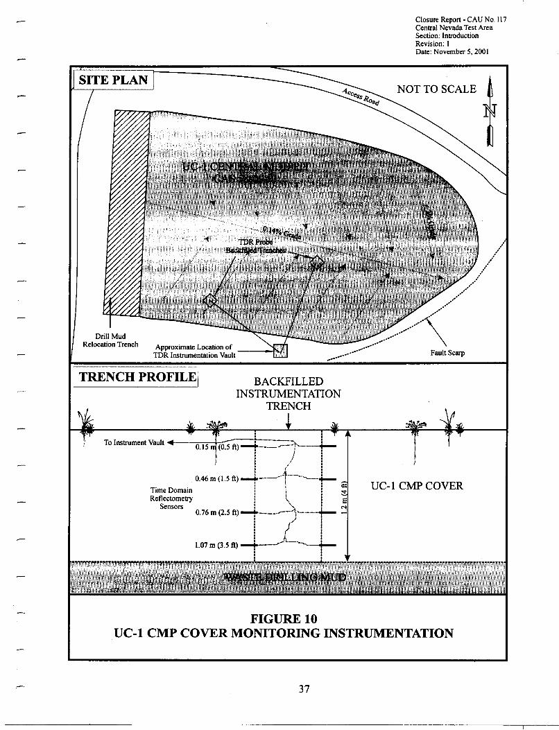
Closure Report • CAU No. 117Central Nevada Test AreaSection: IntroductionRevision: IDate: November 5, 2001
Drill MudRelocation Trench Approximate Location of ---~r;m
TDR Instrumentation Vault
NOT TO SCALE
UC-l CMPCOVER
BACKFILLEDINSTRUMENTATION
TRENCH
· ,· .To Instrument Vault ·--0"15 ~r:=--=:=1'--'---+-
: / :: ..~/ :• ! •: .•:'TL_.._~ :
0.46 m (1.5 ft)~_.__. ! -"~--'--r--
Time Domain ! I ! ~Reflectometry ! \ ! e
Sensors : ~ : N0.76m (2.5 ft) ........_. ..r---)"-'-'---+-- ...;
: (. :· .· .· .· .· .: A :1.07m (3.5 ft) i '.-'---'-.j...-· .· .· .· .
I TRENCH PROFILE!
FIGURE 10UC-l CMP COVER MONITORING INSTRUMENTATION
37
Closure Report - CAU No. 417Central Nevada Test AreaSection: Closure ActivitiesRevision: IDate: November 5.2001
cover that is not transpired by the vegetated cover is directed to the east end of the cover, drainedthrough the designed cut in the cover perimeter berm, and channeled to the east by the eastdiversion channel. Run-off that collects along the south side of the UC-I access road near thecover is directed to the east diversion channel, which outlets to an existing natural drainage.
2.1.8 Disposal of Other Wastes
Scrap metal was uncovered during the excavation of the UC-l CMP mud relocation trench,grading ofthe pre-existing CMP berms, clearing the CMP, during the regrading ofUC-4 Area S,and by general site housekeeping activities. All scrap metal was temporarily piled away fromconstruction activities near the UC-l loading dock. The scrap metal was loaded into end dumptrucks and transported to the NTS scrap yard in Mercury, Nevada. A total of five truck loads,approximately 45.5 metric tons (50 tons) was transported from CNTA to the NTS Area 23 scrapyard between September 17 and 28, 2000. The metal was subsequently recycled as scrap metalby a contracted recycling company. All materials that were not recycled were disposed ofin theNTS Area 23 sanitary landfill.
2.1.9 Decontamination of Equipment
..•..•..
..All heavy equipment used in handling the mud (front-end loaders, dump trucks, tack hoe,bulldozers) were cleaned of any residue. Cleaning was performed by first using hand tools(shovels and bars) to remove dried/caked-on mud, followed by high-pressure washing using a •water master and fire hose. All removed material and water was placed/used in the constructionof the CMP cover. ..Stainless steel scoops used to collect soil samples were decontaminated before and after samplecollection using a laboratory-grade detergent solution, an isopropanol alcohol rinse, and a triplerinse with deionized water. Less than 8 L (2 gal) of detergent solution and rinsate was generatedfrom the decontamination of scoops used to collect samples. The collected rinsate was used inthe construction of the CMP cover.
2.2 DEVIATIONS FROM THE CAP, AS APPROVED
No significant deviations occurred from the approved scope ofwork as outlined in the CAP(DOEINV,2000). The following minor deviations occurred from the approved scope ofwork:
••
• The layout/design ofthe western diversion channel for the CMP was changed tominimize the area disturbed by construction activities, and to reduce the volume ofmaterial required to excavate. This change was documented by issuing Design ChangeNotice Number 00/08-419 included in Appendix C.
38
••..•
Closure Report - CAU No. 417Central Nevada Test AreaSection: Closure ActivitiesRevision: IDate: November 5, 2001
• With NDEP concurrence, UC-1 Area Y (CAS 58-44-06) was clean closed by excavatingapproximately 84 m3 (11.0 yd') ofhydrocarbon-impacted soil and using it in the CMPcover (see Section 2.1.4.3 above) (personal communications, 2000b). Three verificationsamples were collected and analyzed for TPH concentration. The area was regraded, andthe surface scarified to encourage the establishment ofvegetation. Drawing C37(Appendix C) shows the location ofUC-1 Area Y.
• UC-1 Mud Pit E, CAS 58-09-05, was closed by site posting and placement of four abovegrade concrete monuments, during 1999 field activities. During the clean closure byexcavation ofUC-1 Area S, CAS 58-10-03, it was necessary to relocate the southwestcomer monument previously placed for Mud Pit E. The monument was movedapproximately 4.6 m (15 ft) north of its original location to provide better access forexcavation equipment. The monument location was resurveyed and its correct position isshown on the Drawing C25, Appendix C.
• Minor repairs were made to the UC-4 Mud Pit C cover on September 15,2000. Severalsmall erosion rills had formed on the eastern side slope of the cover; A front-end loaderwas used to place and compact clean fill in these rills. All repair work was documentedby photographs and field notes which will be included in the first annual Post-ClosureMonitoring Report. In addition, before demobilizing from UC-4, a motor blade was usedto rip the small staging areas to the west and northeast ofUC-4 Mud Pit C fence line.The staging areas were scarified to approximately 25 em (lOin) bgs to encourage theestablishment ofnative vegetation and reduce erosion.
• Page 10 of the CAP (DOE/NV, 2000) mistakenly stated that CAS 58-44-04, UC-3Area Y would be closed by relocating drilling mud/grout to the CMP cover as ahousekeeping site. Area Y is approximately 283 by 55 m (930 by 180 ft), and is locatedto the southwest ofthe UC-3 emplacement hole. No COCs above action levels werefound at this site during the 1998 site characterization, Appendix D of CADD (DOE,1999). Therefore, a No Action closure alternative was selected for this CAS at stated inthe NDEP-approved CADD (DOE/NV, 1999) and was implemented for CAS closure in2000.
• It was mis-stated in the CAP (DOE/NV, 2000) that CAS 58-19-01 was closed byhousekeeping activities in 1998. This CAS was not located in the field as stated in theNDEP-approved CADD (DOE/NV, 1999). No action was taken to close CAS 58-19-01.
2.3 CORRECTIVE ACTION SCHEDULE, AS COMPLETED
The correctiveaction field activities were performed in two phases. Phase I field activities beganon June 30, 1999, and were completed on October 15, 1999. Figure 2 ofAppendix B of theCAP (DOE/NV, 2000) shows the Phase I field activities as completed.
39
Closure Report - CAU No. 417Central Nevada Test AreaSection: Closure ActivitiesRevision: IDate: November 5. 2001
Phase IT construction activities began on July 17, 2000, and were completed on September 26,2000. Seeding of the cover and the installation ofTDR instruments was completed duringOctober 2000. Transplanting native plant species onto the cover was completed during April2001. A Phase IT field activities schedule, as completed, is shown in Figure 11. Activities suchas post-closure monitoring are ongoing and are not included in this schedule.
2.4 eVA 417 FINAL SURVEY AS-BUILT DRAWINGS
The final engineering as-built drawings for the engineered covers, sites clean closed, and sitesclosed by posting are located in Appendix C. Figure 4 shows a cross section ofthe UC-4 MudPit C cover, and Figure 9 depicts a cross section ofthe UC-l CMP cover as constructed.
40
J
..
..
..
..
•........•....
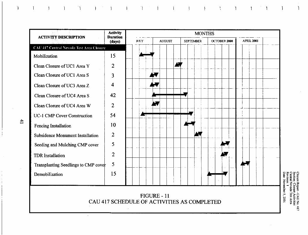
1
Activity MONTHSACTIVJ.T¥DESCRIPTION Duration 1---- -- -- ---~-~._- ---.-~- .-
JULY AUGUST SEPTEMBER OCTOBER 2000 APRIL2001--
II
... ..Mobilization 15
I----
Clean Closure ofUCl Area Y 2 •f--- ------ ------ --- f -_ .. .......,-- --- -----
Clean Closure ofUCl Area S 3 ~ if(
4 ~ lJfi
Clean Closure ofUC3 Area Z------- -_.-. ...... ,-_.- -"._--. --
42 -Clean Closure ofUC4 Area S -Clean Closure ofUC4 Area W 2 til
1-- ._-- -- ---- -_....._- .._.._- f--- ---- ----_... ..........._--_. .,-_.......... -- -_._----_...--UC-l CMP Cover Construction 54 - .. 1i
Fencing Installation 10 ~~I--- ..... - ---- --- ---------- _._-...... -_._---.- -_..._-_._..._-_._---
Subsidence Monument Installation 2 ~
Seeding and Mulching CMP cover 5 .4~1-- -- ------ - ------ --- ---- ..'._----_. ..,--,---..._.-. --_...... -_.._.- .__..",._-_. '---- _..... - -_.__... -'"'---''' ...._--". _._-_........_......._--,,_...,._..__.
TDR Installation 2 .4'"Transplanting Seedlings to CMP cove 5 .1-_ j~
--..-- --- ---,. .__....- _._._- -- ~----- f--- - -- --- f--- ---- --I- -
Demobilization 15 ... 1--
FIGURE- 11CAD 417 SCHEDULE OF ACTIVITIES AS COMPLETED
THIS PAGE INTENTIONALLY LEFT BLANK
42
JJ..•..•..••
•..•..•
••..•
Closure Report - CAU No. 417Central Nevada Test AreaSection: Waste DispositionRevision: 1Date: November 5. 2001
3.0 WASTE DISPOSITION
Wastes generated during the closure ofCAU 417 consisted of scrap metal, sanitary trash, and asmall amount ofpetroleum hydrocarbon-impacted soil.
Scrap metal generated by site activities was hauled to the NTS Area 23 Scrap Yard for salvage.A total of five truck loads, approximately 45.4 metric tons (50 tons), of scrap metal was hauled tothe NTS. The metal was subsequently recycled as scrap metal by a contracted recyclingcompany. All materials that were not recycled were disposed of in the NTS Area 23 sanitarylandfill.
Sanitary trash generated by site activities included paper, plastic, aluminum, and wood. Thiswaste was packaged into 9.2 L (35 gal) trash bags daily (four bags per work day) and transportedto the TTR for disposal. A total of approximately 26.5 rrr' (34.6 ft') of sanitary trash wasdisposed of during 2000 field work.
Petroleum hydrocarbon-impacted materials were removed from heavy equipment during thecleaning activities. All removed materials were incorporated into the UC-l CMP cover.
43
THIS PAGE INTENTIONALLY LEFT BLANK
44
III
..
III
..•...•..III
..•..•
Closure Report - CAU No. 417Central Nevada Test AreaSection: Closure VerificationRevision: IDate: November 5, 2001
4.0 CLOSURE VERIFICATION RESULTS
CAU 417 was closed by implementing one offive closure actions at each CAS: No Action,Housekeeping, Administrative Closure by Site Posting, Clean Closure by Excavation, andclosure in place by constructing an Engineered Cover. Closure verification of the UC-l CMP byconstruction of an engineered cover consisted of a signed CAU 417 SITA ApprovalMatrix/Checklist located in Appendix G. Guidance for the UC-l CMP cover construction andverification was provided in the approved SITA Plan Phase II, Appendix E of the approvedCAP (DOEINV, 2000).
Guidance for the UC-4 Mud Pit C cover construction and verification was provided in theapproved SITA Plan Phase I, Appendix A of the approved CAP (DOEINV, 2000). A copy of thesigned SITA Approval Matrix for the Phase I construction activities is included in Appendix Aof the CAP (DOEINV, 2000).
4.1 DATA QUALITY ASSESSMENT
The closure of CAU 417 did not require the development of formal data quality objectives.Construction of the UC-l CMP and UC-4 Mud Pit C engineered covers were guided by thePhase I and Phase II SITA Plans, respectively. Phase II construction followed a SITA ApprovalMatrix and Checklist provided in Appendix E ofthis document. Phase I construction followed aSITA Approval Matrix and Checklist provided in Appendix A ofthe approved CAP (DOE,2000). For the CASs that were clean closed by excavation, soil verification samples werecollected and analyzed for the presence ofpetroleum hydrocarbons. Sample results are discussedbelow and included in Appendix A. All constructions and sampling QA standards identified inthe CAP (DOEINV, 2000) were met.
4.1.1 VERIFICATION SAMPLE ANALYSES
Five CASs (58-10-03 UC-l Area S, 58-44-06 UC-l Area Y, 58-44-03 UC-3 Area Z, 58-10-02UC-4 Area S, and 58-10-04 UC-4 Area W) were clean closed by the excavation ofhydrocarbonimpacted material. Verification soil samples were collected from 39 locations after theexcavations reached designated boundaries. The samples were collected with decontaminatedstainless steel sampling scoops and placed in labeled 250 milliliter (8 ounce) clear glass samplecontainers and secured with custody seals. The containers were placed in zip-lock plastic bags,in an ice-filled chest, and transported under chain-of-custody to Nevada EnvironmentalLaboratories in Las Vegas, Nevada for TPH analyses. Samples from 39 locations were analyzedfor TPH byU.S. Environmental Protection Agency (EPA) Method 8015M (EPA, 1996).Laboratory quality assurance and quality control results obtained during the analysis of theverification samples are included with the analytical results in Appendix A.
45
-----------------~ --_ .._.~-
Closure Report - CAD No. 417Central Nevada Test AreaSection: Closure VerificationRevision: IDate: November 5.2001
CAS 58-10-03, UC-l Area S Verification Results
Following excavation, five verification samples were collected at UC-I Area S on August I,2000 (Figure 5). One sample, UCISVI, exceeded the NDEP TPH action level of 100 mg/kg.Additional material was excavated from the immediate area around this sample location,approximately 6 by 6 by 0.3 m (20 by 20 by 1 ft) volume ofmaterial was removed. A sixthverification sample (UC1SV6) was collected from the bottom of the second excavation andsubmitted for TPH analysis. This sample did not exceed the TPH action level. After excavatingapproximately 1,177 m3 (1,540 yd') ofhydrocarbon-impacted material, and moving it to theCMP cover, UC-1 Area S is considered clean closed. Sample analytical results are found inTable 3 and in Appendix A.
CAS 58-44-06, UC-l Area Y Verification Results
.,
..III
•Following excavation, two verification samples were collected at UC-I Area Y (Figure 6). Onesample (UCIYV2) exceeded the NDEP TPH action level of 100 mg/kg. Additional material wasexcavated from the immediate area of this sample location; approximately 4.6 by 4.6 by 0.5 m III(IS by 15 by 1.5 ft) volume ofmaterial was removed. A third verification sample (UCIYV3)was collected from the bottom ofthis over-excavated area and submitted for TPH analysis. Thisdeeper sample did not exceed the TPH action level. Therefore, after excavating approximately III84 m' (110 yd') ofhydrocarbon-impacted material, and moving it to the CMP cover, UC-I AreaY is considered clean closed. Sample analytical results are found in Table 3 and in Appendix A.
•CAS 58-44-03, UC-3 Area Z Verification Results
Following excavation of approximately 1,621 m3 (2,120 yd') ofhydrocarbon-impacted material,six verification samples were collected at UC-3 Area Z (Figure 7). No sample exceeded theNDEP TPH action level of 100 mg/kg. Therefore, UC-3 Area Z is considered clean closed.Sample analytical results are found in Table 3 and in Appendix A.
CAS 58-10-02, UC-4 Area S Verification Results
UC-4 Area S is located in a east-west trending drainage ravine just north of the UC-3emplacement hole. Area S was excavated as two distinct areas, the upper western site and thelower eastern site. The area between the upper and lower sites was not extensively excavated ascharacterization results indicated no contaminated material present.
Verification samples were collected from both the upper and lower excavation sites. SamplesUC4SVI and UC4SV2 were collected from a O.3-m (I-ft) thick seam of dark material/mudexposed during excavation of the lower eastern site. The seam was confined to the lowerexcavation area. Results for the two samples were less than the TPH action level.
46
•
•••
•
••
I
Closure Report - CAU No. 417Central Nevada Test AreaSection: Closure VerificationRevision: IDate: November 5. 2001
Samples UC4SV3, UC4SV4, and UC4SV5 were collected from a l-m (3.3-ft) thick dark seam ofmaterial/mud present in the southern wall ofthe upper excavation site. The seam was locatedapproximately 3 m (10 ft) below the top of the berm forming the Area S southern boundary, andappeared to continue south under the berm and beyond the boundary. With NDEP concurrence,the collected samples were analyzed for TPH components, gasoline, diesel, and oil to determineif any long-chain hydrocarbons were present in the stained material (personal communication,2000a). Results for the three samples were less than the TPH Action Level and this informationwas used to bound the lateral extent to the south of the upper area excavation.
Following excavation, 18 verification samples were collected at UC-4 Area S (Figure 8). Threesamples (UC4SV9, UC4SVI2, UC4SVI4) exceeded the NDEP TPH action level of 100 mg/kg,After additional excavation of the immediate area about these sample locations, deeper sampleswere collected (UC4SVI6, UC4SVI7, UC4SVI8) which did not exceed the action level.Sample analytical results are found in Table 3 and in Appendix A.
CAS 58-10-04, UC-4 Area W Verification Results
Following excavation, six verification samples were collected at UC-4 Area W (Figure 8). Nosample exceeded the NDEP TPH action level of 100 mg/kg. Sample analytical results are foundin Table 3 and in Appendix A.
4.2 LAND-USE RESTRICTIONS
CAU 417 has been closed in accordance with the approved CAP (DOE/NV, 2000). Site closureincluded the closure of two CASs by constructing engineered covers, and seven CASs (ninesites) by site posting. The future use of any land related to these 11 sites is restricted from anyactivity that may alter or modify the buried contaminated soil/material as approved by the Stateand identified in this CR unless appropriate concurrence is obtained in advance from the NDEP.
The specific location of the site boundary monuments and fence comers for the 11 sites that arerestricted are given on the CAU Use Restriction Information forms and drawings provided inAppendix F. This information is entered into the NNSAINV Facility Information ManagementSystem and the Central Data Repository. The original CAU Use Restriction Information form isfiled with the CAU 417 project file. In addition, the land-use restriction information will beplaced in the official BLM land withdrawal file (See BLM letter to DOE, Appendix F).
47
THIS PAGE INTENTIONALLY LEFT BLANK
48
..
..
•..•....•..•III
•
••..•
Closure Report- CAU No. 417Central Nevada Test AreaSection: Post-Closure MonitoringRevision: IDate: November 5. 2001
5.0 POST-CLOSURE MONITORING PLAN
Post-closure monitoring of the CNTA sites is intended to determine:
• If maintenance and repairs to the UC-I CMP or the UC-4 Mud Pit C covers, fences, anddiversion channels are needed.
• If the UC-I CMP or UC-4 Mud Pit C covers are subsiding.
• If the UC-I CMP cover is performing as designed.
• The state of the health of the vegetation on the UC-I CMP cover.
• Ifmaintenance and repairs to the above-grade monuments and warning signs are needed.
• Ifmodifications to the use restriction administrative controls are needed.
Table 1 lists 24 CASs (29 sites) that were closed by taking no action or by housekeepingactivities. Sites include those having no COCs above Action Levels, housekeeping sites thathave been remediated, two septic tanks that were closed in place by backfilling with clean soil,and two USTs that were removed. These sites do not require any post-closure monitoring orinspections. In addition, the five CASs that were closed by excavation and limited regrading(Table 1), also require no post-closure monitoring. In total, 29 CASs (34 sites) do not requireany post-closure monitoring.
5.1 POST-CLOsuRE MONITORING REQUIREMENTS
The components of the CNTA post-closure monitoring plan are provided below.
5.1.1 Site Inspections
Post closure inspections of CAU 417 will be done quarterly, four times a year. Site inspectionswill include visual observations of the UC-I'and UC-4 covers, and all above ground monuments,attached warning signs, and survey pins. Each site inspection will be documented on a siteinspection form and with site photographs. The post-closure inspection will consist of thefollowing:
• A detailed visual inspection of the UC-I CMP cover and the UC-4 Mud Pit C coverfencing. The perimeter of the fencing at both covers will be walked by the inspector andthe condition ofthe barbed wire and the chicken wire fencing, warning signs, and
49
Closure Report - CAU No. 417Central Nevada Test AreaSection: Post-Closure Monitoring ..Revision: IDate: November 5, 2001
entrance gate and lock will be documented. ..
•
•
•
A visual inspection of all above-grade monuments, attached warning signs, and affixedsurvey pins placed at UC-I, UC-3, and UC-4 sites for signs ofwear, disturbance,vandalism, presence of animal burrows, etc. Repairs to monuments and/or attached signswill be made during site inspection visits, or if necessary scheduled for later in thecalendar year.
Determine the condition of the two subsidence monuments on the UC-4 cover, and the 12subsidence monuments on the UC-I CMP cover. In addition, twice a year all subsidencemonuments will be surveyed to determine if the covers have subsided.
Any changes to the cover or fenced area will be documented. Specific changes include,but are not limited to, the presence of trash/debris inside the fenced area, animal burrowson the cover or under the perimeter fence, the presence oferosion features on the cover,cover side slopes, or diversion channels. Any changes in the health of the CMP covervegetation will also be documented.
..III
•..
5.1.2 Cover Monitoring ..The UC-I CMP cover was designed to limit infiltration into the underlying waste unit byremoving soil moisture from the cover by transpiration by vegetation on the cover surface. Theeffectiveness of the cover design will be determined by monitoring soil moisture content in thecover. Soil moisture content will be measured by TDR sensors buried at various depths in thecover. ..TDR sensors were buried in the cover at two locations during cover construction (see Section2.1.7.7 and Figure 10). At each location two TDR sensors were placed at 0.15,0.46,0.76, and1.07 m (0.5, 1.5,2.5 and 3.5 ft) below the surface of the cover (Figure 10). The TDR nests arelocated approximately 48 m (157 ft) northwest and 48 m (157 ft) northeast of the location of theinstrument vault located off the southern edge of the cover (Figure 10, Drawing WI, AppendixC). Data is collected once per day from each TDR sensor and stored in a datalogger located inthe instrument vault. The stored TDR data and precipitation data are retrieved periodically bysatellite link for processing and analysis.
5.1.3 Compliance Criteria
The CNTA UC-I CMP cover boundary is defined by the fence installed around the cover. Thefence encloses approximately 6 hectares (14.8 acres). The point ofcompliance for the UC-Icover is the depth ofthe deepest TDR soil moisture probe (approximately 1.07 m [3.5 ft] bgs).Cover compliance will be based on the soil moisture content of the cover. The specific criteria
50
•lit
•..••••
Closure Report - CAU No. 417Central Nevada Test AreaSection: Post-Closure MonitoringRevision: IDate: November 5. 2001
will not be set until the cover has had sufficient time to reach equilibrium. Once the soilmoisture content within the cover has reached equilibrium, soil moisture trigger values will beagreed upon with the NDEP.
If soil moisture data indicate that the cover is not operating according to established compliancecriteria, the NDEP will be notified ofthe noncompliance within 14 days. After NDEP has beennotified ofnoncompliance, a work plan will be submitted to the NDEP within 90 days outliningthe proposed remediation/investigation plan. All corrective actions will be documented in theannual Post-Closure Monitoring Report.
5.1.4 Site Maintenance and Repair
If a site inspection shows conditions that require major repairs, or that either the UC-l CMPcover or UC-4 cover are not in compliance, the NDEP will be notified and a work plan proposingthe corrective actions prepared and submitted to the NDEP within 90 days.
• Non-critical cracks, animal burrows, settling features less than 15 em (6 in) deep will berepaired by hand during site inspection visits.
• Minor features such as the presence of small mammal burrows, cracks, settlingimperfections, or erosional rills «15 em [6 in]), etc., will be repaired during inspectionvisits, or ifnecessary, scheduled for repair on an annual basis.
• In critical areas (on side slopes adjacent to the cover, or on the cover itself), cracks,settling features, erosional rills, animal burrows larger than 15 em (6 in) deep whichextend 1 m (3 ft) or more will be evaluated and repaired within 60 days of detection.
• Twice a year the 12 subsidence monuments on the UC-l CMP cover and the twosubsidence monuments on the UC-4 Mud Pit C cover will be surveyed to determine if thecover has subsided.
• Damage to the fencing surrounding the UC-l cover and the UC-4 cover will be evaluatedand repaired within 60 days of detection.
All repair work will preserve the original cover "as built" design and will be documented in theannual post-closure inspection report. If repair of the cover requires modification to the coverdesign, the NNSNNV will present a formal design modification request to the NDEP prior tomaking the repairs.
51
Closure Report - CAUNo. 417Central Nevada Test AreaSection: Post-Closure Monitoring iiiRevision: IDate: November 5. 200 \
5.1.5 Annual Reporting IIIIi
A post-closure inspection will be made twice a year for five years following completion ofclosure field activities. All inspection and maintenance activities conducted during the year will IIIibe documented and included in the annual monitory report. The annual Post-Closure MonitoringReport will be submitted by the NNSA/NV to the NDEP and will include the followinginformation: ..
• A brief narrative and discussion of all post-closure inspection activities and observations.•
• Copies off all completed inspection checklists (Appendix H) and maintenance records.
• UC-l CMP soil moisture content profiles through the previous year.
• Survey settlement data. IIIi
• Maintenance and repair documentation (if any).
• Specific recommendations for non-standard maintenance or changes in post-closuremonitoring.
All closure and post-closure monitoring documentation will be retained in project files and willbe available on request.
52
•
•....
..•IIIIi
..

Closure Report - CAU No. 417Central Nevada Test AreaSection: Summary & Recom.Revision: 1Date: November 5. 2001
6.0 SUMMARY AND RECOMMENDATIONS
6.1 SUMMARY
The following site closure activities were performed at the 34 CASs comprising CAU 417 andare documented in this report:
• No closure action was taken at 13 CASs (17 sites): 58-05-01,58-07-01,58-05-04,58-09-05 (Mud Pits C and D only), 58-35-01, ~8-05-02, 58-09-06 (Mud Pits A, B, C, andD), 58-10-06, 58-19-01,58-35-02, 58-44-04, 58-05-04, and 58-09-03 (Mud Pit E only).
• Housekeeping activities, collecting scrap materials, and transporting to approved landfillsites at the NTS were used to close seven CASs: 58-44-01,58-44-02,58-44-05,58-98-03,58-98-01,58-98-02, and 58-98-04.
• Two CASs (58-05-03 and 58-99-01) were closed by excavation and removal ofUSTs.
• Two septic tanks (CASs 58-05-05 and 58-05-06) were closed by backfilling with cleanfill.
• Site posting with above-grade monuments and attached warning signs and land-userestrictions were used to close seven CASs (nine sites): 58-09-02,58-09-05 (Mud Pit Eonly), 58-09-06 (Mud Pit E only), 58-10-01, 58-25-01, 58-09-03 (Mud Pits A, B, and D),and 58-10-05.
• Clean closure by excavation soil with TPH levels greater than the NDEP action level of100 mg/kg and limited regrading was used to close five CASs: 58-10-03,58-44-06,58-44-03,58-10-02, and 58-10-04.
• Construction of engineered covers was used to close in place two CASs: 58-09-01 and58-09-03 (Mud Pit C only). Following construction, a fence was constructed around eachcover to prevent damage to the cover or intrusion by wildlife.
6.2 RECOMMENDATIONS
Since the closure activities for CAU 417 have been completed following the NDEP-approvedCAP (DOEINV, 2000) as documented in this CR, the NNSAINV requests:
• A Notice ofCompletion be provided by the NDEP to NNSAINV for the closure ofCAU 417 (CAS 58-05-01, 58-07-01, 58-09-01, 58-09-02, 58-09-04, 58-09-05,58-10-03,58-35-01,58-44-01,58-44-02,58-44-05,58-44-06, 58-98-03, 58-05-02, 58-05-03,58-05-05, 58-05-06,58-09-06,58-10-01,58-10-06,58-19-01, 58-25-01, 58-35-02,
53
Closure Report - CAU No. 417Central Nevada Test AreaSection: Sununary & Recom.Revision: 1Date: November 5, 2001
58-44-03,58-44-04,58-98-01,58-98-02,58-98-04, 58-99-01, 58-05-04, 58-09-03,58-10-02, 58-10-04, 58-10-05)
• CAU 417 be moved from Appendix ill to Appendix N of the FFACO "ClosedCorrective Action Units."
•
54
•
•
1
•
II
Closure Report - CAU No. 417Central Nevada Test AreaSection: ReferencesRevision: IDate: November 5, 200 I
7.0 REFERENCES
BN, see Bechtel Nevada.
Bechtel Nevada, 2000a. Field Management Plan for Corrective Action Unit 417 Central NevadaTest Area Surface. Nevada, Las Vegas, NV.
Bechtel Nevada, 2000b. Site Specific Health and Safety Plan for Closure Activities for the CentalNevada Test Area: CAU 417, Revision 1, Las Vegas, NV.
DOEINV, see U.S. Department ofEnergy, Nevada Operations Office.
EPA, see U.S. Environmental Protection Agency.
FFACO, see Federal Facility Agreement and Consent Order.
Federal Facility Agreement and Consent Order of 1996 as amended. Agreed to by the NevadaDivision of Environmental Protection, U.S. Department ofEnergy, and U.S. DepartmentofDefense.
Levitt, Dan. 2001. Personal communication to K. Campbell, Bechtel Nevada EnvironmentalRestoration.
Nevada Administrative Code, 1996. NAC 445A.2272, "Contamination of soil: Establishment ofaction levels," As adopted by the Nevada Environmental Commission, October, CarsonCity, NV.
Sanders, Peter. 2000a. Personal communication from Paul J. Liebendorfer, P.E., ChiefDepartment of Conservation and Natural Resources, Nevada Division of EnvironmentalProtection, during August 16, CNTA site visit.
Sanders, Peter. 2000b. Personal communication from Sig Jaunarajs, Nevada Division ofEnvironmental Protection.
U.S. Department ofEnergy, Nevada Operations Office, 1997. Corrective Action InvestigationPlan for Central Nevada Test Area CAU No. 417, Revision 0, DOEINV-450, Las Vegas,NV.
U.S. Department of Energy, Nevada Operations Office, 1998. Nevada EnvironmentalRestoration Project. Health and Safety Plan, Revision 3, Las Vegas, NV.
U.S. Department ofEnergy, Nevada Operations Office, 1999. Corrective Action DecisionDocument for Corrective Action Unit 417: Central Nevada Test Area Surface. Nevada,Revision 1, DOEINV-524, Las Vegas, NV.
55
Closure Report - CAU No. 417Central Nevada Test AreaSection: References •Revision: IDate: November 5. 2001
U.S. Department ofEnergy, Nevada Operations Office, 2000. Corrective Action Plan for IIICorrective Action Unit 417: Central Nevada Test Area Surface. Nevada, Revision 0,DOE/NV--588, Las Vegas, NY.
IIIU.S. Environmental Protection Agency, 1996. Test Methods for Evaluating Solid Waste.
PhysicaVChemical Methods, EPA Publication SW-846, Third Edition.
Wycoff, Runore, 1998. Letter to Paul J. Liebendorfer, P.E., ChiefDepartment of Conservationand Natural Resources, Nevada Division of Environmental Protection, December 30,1998.
IIIll
•
..
56
APPENDIX A
VERIFICATION SAMPLINGANALYTICAL RESULTS
THIS PAGEINTENTIONALLY LEFTBLANK
•....
•
•..
II
••
•
•....
•
CLIENT:
ATIN:
NEL LABORATORIESReno • Las Vegas • Boise
Phoenix • Sacramento
BechtelNevadaP.O. Box 98521,MISNTS273Las Vegas,NV 89193-8521Ted Redding
Las Vegas Oivisiol4208 Arcata Way. Suite A • Las Vegas. NV 89031
(702) 657-1010· Fax: (702) 657-15~1-888-368·328:
PROJECI'NAME: V853PROJECI'NUMBER: 17777
NELORDERID: LOOO8027
Attachedare the analyticalresults for samplesin supportofthe abovereferenced project.
Samplessubmittedfor thisproject were not sampledby NEL Laboratories. Sampleswere receivedby NEL ingood condition. under chain ofcustodyon 8/2/00.
. Shouldyou have any questionsor comments, please feel free to contactour ClientServicesdepartmentat (702)657-1010.
r
~o/bate
CERTIFICATIONS:Reno Las Vegas S. California Reno LasVegas S. California
Arizona AZ0520 AZ0518 AZ0605 Idaho Certified Certified"""" California 1707 2002 2264 Montana Certified Certified
US ArmyCorps Certified Certified Nevada NV033 NVOS2 CA084ofEngineers L.A.C.S.D. 10228
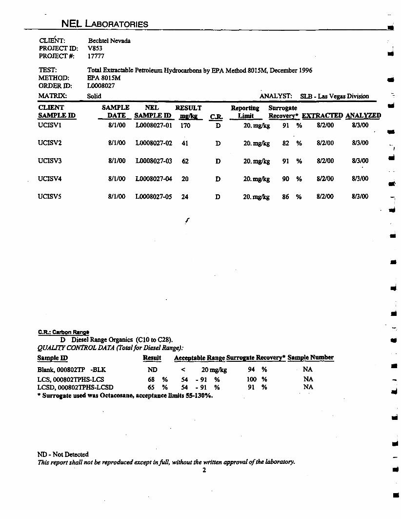
NEL LABORATORIES •
Total Extractable Petroleum Hydrocarbons by EPA Method 8015M, December 1996EPA8015M ..L0008027
Solid ANALYST: SLB - Las Vegas Division --
SAMPLE NEL RESULT Reporting Surrogate iiiDATE SAMPLEID mglkg g Limit Recovery* EXTRACI'ED ANAL¥ZED
811100 L0008027-o1 170 D 20.mg/kg 91 % 8/2/00 813/00
•8/1100 LOOO8027-02 41 D 20.mgIkg 82 % 812100 813/00
8/1100 LOOO8027-03 62 D 20.mg/kg 91 % 812100 813100 ..811100 L0008027-04 20 D 20.mglkg 90 % 8/2/00 813/00 ..811100 LOOO8027-05 24 D 20.mg/kg 86 % 812100 813/00 -,
...I'
•
CLIENT:PROJECI'ID:PROJECI'#:
TEST:MElHOD:ORDERID:
MATRIX:
CLIENTSAMPLEID
UCISVI
UCISV2
UClSV3
UClSV4
UClSV5
Bechtel NevadaV85317777 III
•...
•C.R.: Carbon Range
D Diesel Range Organics (CI0 to C28).QUALITYCONTROL DATA (Total for DieselRange):Sample In Result Acceptable Range Surrogate Recovery* Sample Number
Blank, 000802TP -BLK NO < 20 mg/kg 94 % NA
LCS,000802TPHS-LCS 68 % 54 - 91 % 100 % NALCSD,000802TPHS-LCSD 65 % 54 - 91 % 91 % NA* Surrogate used was Oetaeesane, acceptance Umits 55-130%.
NO - Not DetectedThisreport shall not bereproduced except infull, withoutthe written approvalofthe laboratory.
2
..•
III
III
•
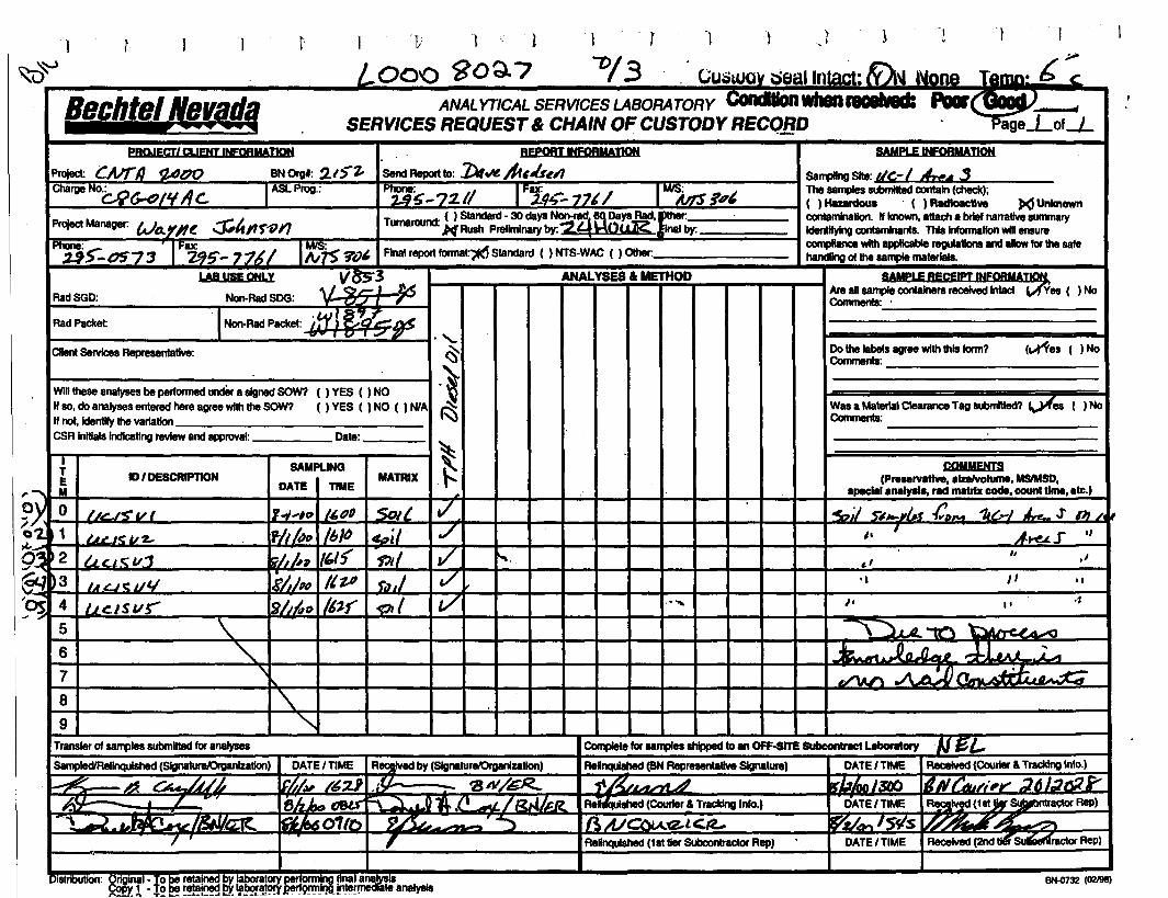
1
BechtelNevada
V 1 1 I T "II J )! I~
L00'0 ~:?o:;).7 "1)/3 . CUlilUQV tleallnlal:t: &M "nnn.6 ..ANALYTICAL SERVICES LABORATORY CondtIon....1IGIIv8d: Fa , '4
SERVICES REQUEST & CHAIN OF CUSTODY RECQ,BD "l5"age.Lof.....LREPORTINFORMATION
'5endReportto: lAteN. /11~~~~~pt;:;~-72.// IFi4~_ 77'/ I~ .i'"Turnaround' ( ) Standard - 30 days~~~,DaYS.f!!!t. r~·_··-----.H Rush Prelinlnary by: InuJ'£ Elnal by.
~ VOl, final reporttonna~ Standard ( ) NTS-WAC ( ) Other:
PROJECT' a.IENT INFORMATION
Project: CAlrl1tJAl7O BNOrgl: 2.r5"'z,Charge N°'i::..l;t;..D/lfAc. ASl Prog.:
ProjectManager: WtJ.YIf~ .:s;,/'flr-o;J'2JS:0S'73 IF~5'- 7'7,(/
LAB USE ONLJ
(~es ( )No
RadSGD:
RadPackel:
ClIent ServIces Representative:
VBs"3 ANALYSES & METHOD
Non-RadSOO: ~,,;,!.J6SAMpLE RECEIPTINFOA~
Areansample contaJnera receivedIntactuYes ( ) NoComrnenIs:_' _
Dothe labelsagreewithIhIsform?Comments: _
Win theseanalyses be performedllncl8r a signed SOW? () YES ( ) NOII so,do analyses entered here agree with the SOW? ( ) YES ( ) NO ( ) NlAII not,ldentifylhe varlatlon _
CSRInitialsindicating review and approval: Date: _
Wasa Material Clearance Tag 8UbmIIted? ~es ( ) NoComments:
,J
.,"J'.."
COMMENTS(Pre..rvatlve, .Izelvolume, MSIMSD.
...-cIa! analyal., ... rnatrbl code, count time,etc.)
"'»;/ 5'~.1'~1 -CalNl 11&1 J-.. .r OJ /. ~I' ' .AHU. S .,
.- ....
".
MATRIXSAMPlING
DATE nME
1'..,....,0 '''(lfJ SoIl.1/' 1tJt1 Ib~ :4.:JillvlJl~p ,,,, -rJdIEh/p# IIV f" IIs,,~~ 1/1'-1' 'fJI1
\.
10'DESCRIPTION
IJL~<vl
t..lL.J(;.Uz..
U<..l" v.11.t£JC ~l/
u.ctsus"
7
6
{E,_ M
O\) 0
~1)L.A-.....-&.o&.II'.:;.....--_......--1F"""~.......;.,;..~f-9lI~-+-~ ......-+--+---1I---+-+---1I---+--I--f--+--I----~-----~==-----I~2.J~-f-lIlI=lIo.:l:;i""""lo.;;",lIIl;------1I1f'~-f----f.....;,;.;.&..-~"7t--+--+--1i---t--+---1I---+-....--:t--+-....-~-----------....E'/)3
~OS 45
8
9Transler01 S8Il1lIes submItIed foranalyses Completeforsamplesshipped toan OFF-8ITE Subcontract ubcniory ·IJ~'-8ampledlRellnquished (SignatureJOrganlzallon)
I
DATE'TIME Rqlved by (SignalUre.'Organlzatlon)
fhlN /~Z1 ." I. - 'a JII/GR-e~ ~c:;;;,. :l .0 l'./' ~/,~ " ..-~o1(o S'~. - ~,
Relnqulshed (BN Representative SIgnature) DATEI TIME ReceIved (Courier& TrackingInlo.)
dU ~ A 'rrJ~'-J$f1:J !IJNt:tJul''''Y- "JAL"~1r'
Re (Courier& TrackingInfo.) DATE' TIME ~lved (1st~ ..,.....uaetor Rep)
Relinquished (1st tier Subcontractor Rep) DATE' TIME ReceIved(2nd tI4r~ractor Rep)
BNo0732 (o:?J98)
CLIENT:
ATIN:
NEL LABOh~TORIESReno • Las Vegas • Boise
Phoenix • Sacramento
BechtelNevadaP.O. Box 98521, MIS NTS273Las Vegas,NY 89193-8521Dave Madsen
las Vegas Divisic4208 Arcata Way, Suite A • las Vegas. NV 890~
(702) 657-1010· Fax: (702) 657-1571·888·368-321:
PROJECT NAME: V870PROJECTNUMBER: 17777
NEL ORDERID: LOOO8129
Attachedarc the analytical results for samples in supportofthe abovereferencedproject.
Samples submittedfor thisproject werenot sampledby NEL Laboratories. Sampleswere receivedby NEL ingood condition, under chainofcustodyon 8/10/00.
Shouldyou have any questions or comments, please feel free to contactour ClientServicesdepartment at (702)657-1010.
"3hJmDate
CERTIFICATIONS:Reno. Las Vegas
ArizonaCaliforniaUSArmy CorpsofEngineers
AZ0520 AZ05181707 2002Certified Certified
S. CaliforniaAZ06052264
IdahoMontanaNevadaL.A.C.S.D.
Reno Las Vegas S. CaliforniaCertified CertifiedCertified CertifiedNV033 NY052 CA084
10228
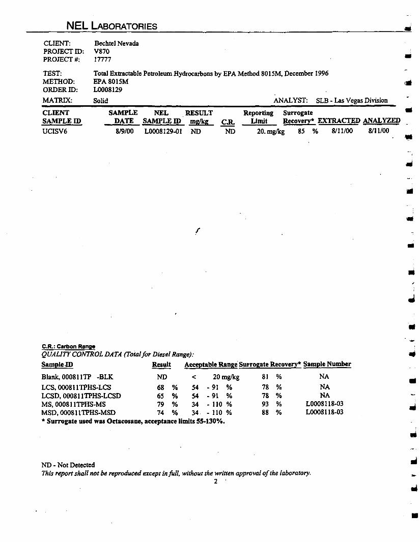
NEL LABORATORIES
Bechtel NevadaV87017777 •
SLB - Las Vegas DivisionANALYST:
Total Extractable Petroleum Hydrocarbons by EPA Method 8015M, December 1996EPA801SMLOO08129
Solid
CLIENT:PRomcrID:PROJECf#:
TEST:METHOD:ORDERID:
MATRIX:
CLIENTSAMPLEID
UCISV6
SAMPLEDATE
819/00
NEL RESULTSAMPLE ID mglkg
L0008l29-01 NOCoR.
NO
Reporting SurrogateLimit Recovery* EXTRACTED ANAL¥ZED
20. mg/kg 85 % 8111/00 8111/00
..r
III
•
..-C.R.: Carbon Range
QUALITYCONTROL DATA (Totalfor DieselRange):
SampleID Result Acceptable Range Surrogate Recovery* Sample Number
Blank, 000811TP -BLK NO < 20 mg/kg 81 % NA
LCS, 000811TPHS-LCS 68 % S4 - 91 % 78 % NALCSD, 000811TPHS-LCSD 65 % 54 - 91 % 78 % NAMS, 000811TPHS-MS 79 % 34 - 110 % 93 % L0008118-03MSD, 000811TPHS-MSD 74 % 34· - 110 % 88 % L0008118-03* Surrogate used was Octacosane, acceptance limits 55-1300/••
..
NO - Not DetectedThis reportshall not be reproducedexcept infull. withoutthe written approvalofthe laboratory.
2 ',.,...•

\ 1 1 I t ) l
Bechtel Nevada.......................ANALYTICAL SERVICES LABORATORY
SERVICES REQUEST& CHAIN OF CUSTODY RECORD Page J of (
ProjectManager: LvJIl Y~ -::J<,~tlj07YJ
Phonei."fS-- 051~ IF8X":2..,S-- 77 / 1 I~ 3{)~
REPORTINFOR~~
send Reportto: Dll"~ II.. te:
p~.,.- 72.11 IFax:21'')- -17M IMI5~.H"6Turnaround' ( ) Standard- 30 daysNon-~?:!! ~ts Rad, Other: _
. W-Rush Pl1llimlnary by. YJ 1:"11() U Rnal by.
Final reportformat: ( ) Standard ( ) NTS-WAC ( ) Other:
()LYes ( ) No
COMMENTS(P.....rvatlve. alzelvolume, MSIMSD.
apeclalanalyala, rad matrix code, count time. etc.)
SAMPLE RECEIPTINFORMApgtt~san:'econtainers received Intact \c':) Yes ( ) No
00 the labelsagree with thisform?Comments: _
Was a MaterialClearance Tag submitted? (\h Yes ( ) NoComments: T:-----------
ANALYSES. METHOD
./
MATRIX
()YES()NO( ) YES ( ) NO ( ) NlA
SAMPUNG
DATE nME
YBUSEONLY
Non-RadSOG: \Jg 1-0INon-RadPacket: LV Iq J'f
IDI DESCRIPTION
3
ITEM
2
AadSGD:
Wilthese analysesbe performed undef a signed SOW?If BO,do analysesentel1ld hel1lagreewiththeSOW?If nol, identifythe varlalion _
CSR initialsIndlcatingreviewandapproval: Date: _
RadPacket:
Clientservices Representative:
l'( 01
4
5
6
7
.'1ft'CII-- .....-
l ./8
9Translerof samplessubmittedfor analyses Complete for samplesshipped toan OFF-srrE SUbcontrlct LabcntOl'y I.JE!LSampledlAe!inquished (Slgnatul1llOrganizalion) DATE' TIME Received by (SignaturelOrganizalion) Relnqulshed (BN Representative Slgnatul1l) DATE' TIME Received (Courier& Tracking Info.)
- 1
ReU':'lfllshed(Courier& TrackingInfo.) D~E ,'rIME RecelvedjsJ,le/Subcontraetor Rep)
IIT~ r ·Alnrt... t 1LfL, V'o-ltJHo "4 ,£, .fYA. ~ReUnqulshed (1st tier SubcOntractor Rep) CATE' TIME R~ (2ndIier Subcontractor Rep)
IBN.Q732 102198\
..- CLIENT:
ATIN:
NEL LABORATORIESReno. Las VegasPhoenix. Boise
Bechtel NevadaP.O. Box 98521, MiS NTS273Las Vegas, NY 89193-8521Dave Madsen
Las Vegas Division4208 Arcata Way, Suite A • Las Vegas, Nevada 89030
702-657-1010. Fax: 702-657-15771-888-368-3282
PRomCf NAME: V884PROmCf NUMBER: 17777
NEL ORDER ID: L0008325
Attached are the analytical results for samples in support of the above referenced project.
Samples submitted for this project were not sampled by NEL Laboratories. Samples were received by NEL ingood condition, under chain of custody on 8/28/00.
Should you have any questions or comments, please feel free to contact our Client Services department at (702)657-1010.
Stan VanWagenenLaboratory Manager
CERTIFICATIONS:Reno Las Ve~as
-ArizonaCaliforniaUS Anny Corpsof Engineers
AZ0520 AZ05181707 2002Certified Certified
S, CaliforniaAZ06052264
IdahoMontanaNevadaL.A.C.S.D.
Reno Las Vel:as S. CaliforniaCertified CertifiedCertified CertifiedNV033 NY052 CA084
10228
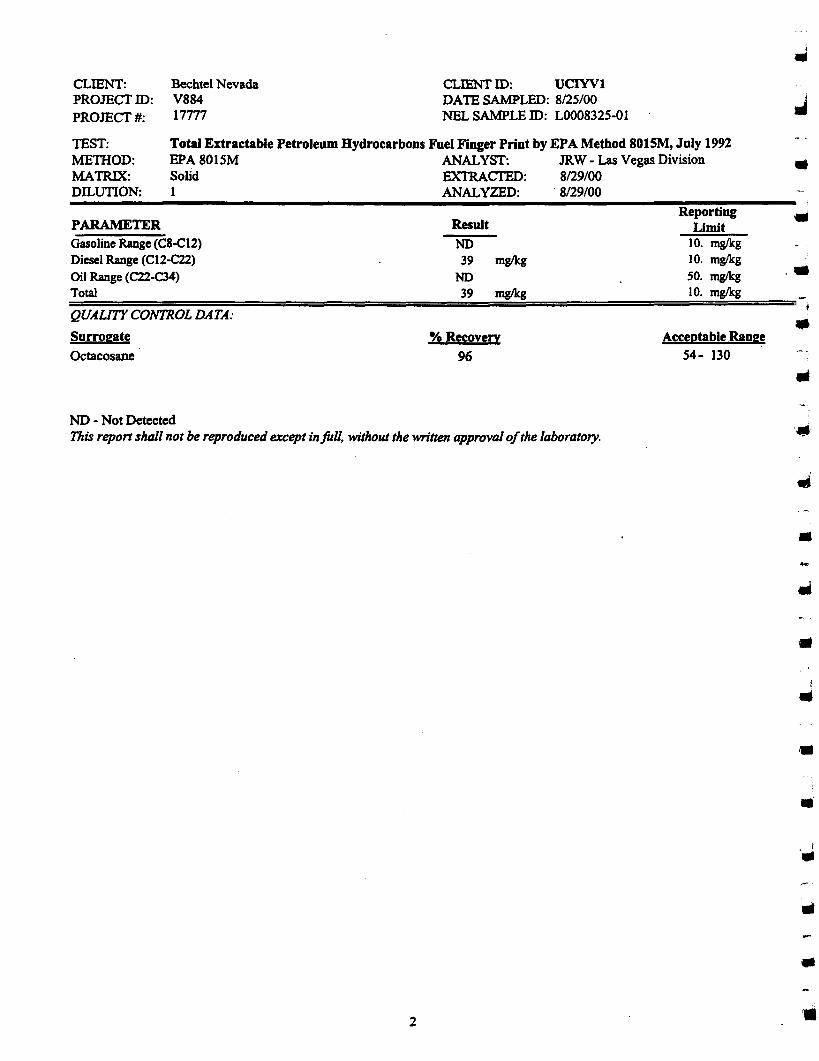
Total Extractable Petroleum Hydrocarbons Fuel Finger Print by EPA Method 801SM, July 1992EPA 8015M ANALYST: JRW - Las Vegas DivisionSolid EXTRACTED: 8/29/00I ANALYZED: . 8/29/00
CLIENT:PROJEcrID:PROJEcr#:
TEST:MEmOD:MATRIX:nrurrrox
Bechtel NevadaV88417777
CLIENT ID: UCIYVIDATE SAMPLED: 8/25/00NEL SAMPLE ID: L0008325-01
•PARAMETERGasoline Range (C8-C12)Diesel Range (CI2-C22)Oil Range (C22-C34)Total
QUAUTY CONTROL DATA:
SurrogateOctacosane
ResultNO39 mg/kg
NO39 mg/kg
% Recovery
96
ReportingLimit
10. mg/kg10. mg/kgSO. mglkg10. mg/kg
Acceptable Range54- 130
••
ND - Not DetectedThis reportshall not be reproducedexcept infull, withoutthe written approval0/the laboratory.
2
•
••
..••
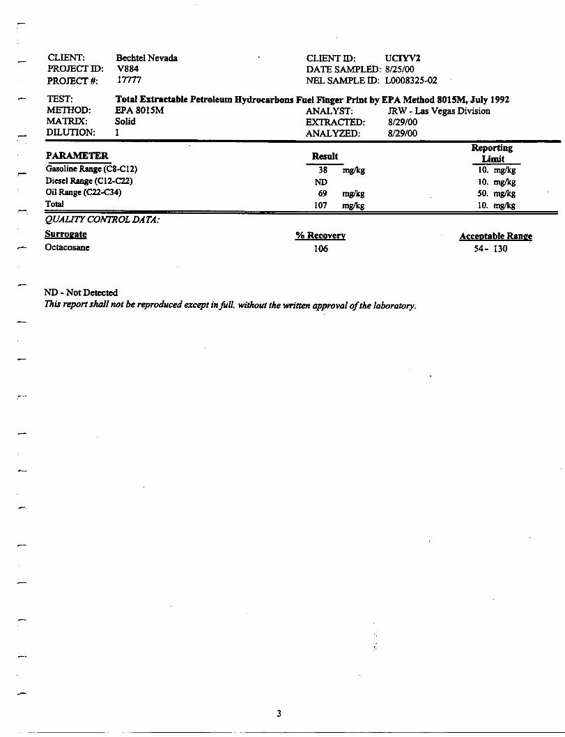
Total Extractable Petroleum Hydrocarbons Fuel Finger Print by EPA Method 8015M, July 199ZEPA 801SM ANALYST: JRW - Las Vegas DivisionSolid EXTRACTED: 8/29/001 ANALYZED: ·8/29/00
CLIENT:PROJECfID:
PROJECf#:
TEST:METIIOD:MATRIX:DILunON:
Bechtel NevadaV88417777
CLIENT ID: UCIYVZDATE SAMPLED: 8/25/00NEL SAMPLE ID: LOO08325-02
PARAMETERGasoline Range (C8-CIZ)Diesel Range (CI2-ell)Oil Range (C22-C34)Total
QUAUTY CONTROL DATA:
Surrogate
Octacosane
Result
38 mg/kg
NO69 mg/kg
107 mg/kg
% Recovery
106
ReportingLimit
10. mg/kg
10. mg/kg
SO. mg/kg
10. mg/kg
Acceptable Range54- 130
ND - Not DetectedThis report shall not be reproduced except injull. without the written approval ofthe laboratory.
3
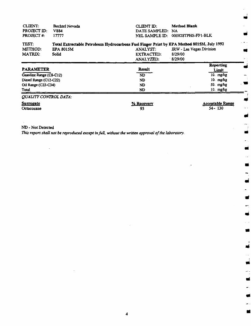
CLIENT:PROJEcrID:PROJEcr#:
Bechtel NevadaV88417777
CLIENT 10: Method BlankDATE SAMPLED: NANEL SAMPLE 10: 000828TPHS-FPI-BLK
l•
TEST:METIIOD:MATRIX:
Total Extractable Petroleum Hydrocarbons Fuel Finger Print by EPA Method 8015M, July 1992EPA 8015M ANALYST: JRW· Las Vegas DivisionSolid EXTRACTED: 8/29/00
ANALYZED: . 8/29/00
•PARAMETERGasoline Range (C8.CI2)Diesel Range (CI2-C22)Oil Range (C22-C34)Total
QU.A.UTY CONTROL DA.TA:
SurrogateOctacosane
Result
NONONONO
% Recovery93
ReportingLimit
10. mg/kg10. mg/kgSO. mglkg10. mg/kg
Acceptable Range54- 130 .
••
NO • Not DetectedThis report shall not be reproducedexcept infull, without the written approvalofthe laboratory.
4
•
•
III
•
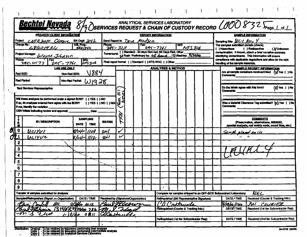
) I 1 ) 1 1 1 1
Irlchtsl Ns,p"a n... A_ ANALYTICAL SERVICES LABORATORY / ~A/I'17\ ('}7Z r-E ....... onUSERVICESREQUEST&CHAIN OFCUSTODY RECORD tJ/vu. 0./ )Page..Lo'.L
ProfecI: t::UTA~ r'I", BN0rgI: :Jjt;")..
1D1a,geNo·~9e;..:,14A~ I~~~u
ProjectManager: W ~y,u. .:;r.,LItfI~ Y1
Phone: ' I,.ax: I ~~-U~- 0'-("7 3 2/(~- 77'1 1~30'
.BEPCIIT IFOBMAIQI
SIInd Report 10: ~VI! Ihll tI"PI
1~~-7J..1/ IFIr,..,S'"_ 7 U '/ IMfS
:IV7_C; '?vA( ) SIandInI· 30 day8NcJn.rad. 80 Days Rad,0Ihllr.
Tumlround: bfRush PfeImktary by: !dhwa§' :"2~·---:I!n/::-:JO~iR)--
FInIIreport formal: ( ) Standard ( ) NTS·WAC ( ) Ohlr.
RadSGD:
f)6VH ( )No
W..a Me.....aea,.. TagUlmIIIlId'I ~VU ( )NoCommenIa: ----------
fWIII.E BECEti 1NfQB1IA~ .Aled .....,.. corUlnIra recelved InIacI Ve. ( )NoCommenIa:
'-~--------
Do..1IbeII....wlI\ tillonn?ca••ulnll: _
ANALYSES .. METHODUIUSEQNLY
-'..... ~I
WI beperIonned 1Igned SON? ( ) YES ( ) NO QlN10, do enliIfedhint aGree SON? ( ) YES ( ) NO ( ) HlA u1 c
" not,IdIIlIfr lie varlalon VCSA""1ndIcaIIng review andappronI: Dale: _
COMMENTS(PrHervaUft, 1IIeIvoI...... MSlMSO•......anal"'" rad matIIa code. count uma.ete.)
!ZJ(..,A6 .h-JA", Ii,
r :' It
2
3\
I /If ( f IfA .'-R4
5.6
7
89
ReInquIshed (BN~lIve SIgnature) DATE'TIME Reoelved(Courier & Tracldnllinlo.)
AeInquiIhed (CourIer aTraddngInfo.) DATEf'TIME Received (hIller SUbconIraclor Rep)
:mrIf pe lelaI",,:
Relnqulshed (tllller &Dxnraca Rep) . DATE 'TIME ReceIved (2nd IieI Subc;onIractllf Rep)
llN-Clm (02191'
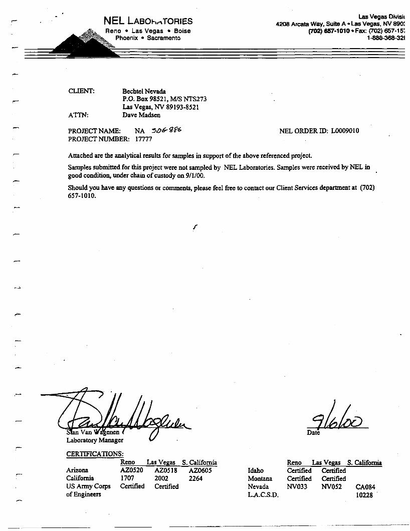
CLIENT:
A1TN:
NEL LABOl-tnTORIESReno • Las Vegas • Boise
Phoenix • Sacramento
BechtelNevadaP.O. Box 98521, MIS NTS273Las Vegas, NY 89193-8521Dave Madsen
Las Vegas Divisic4208 Arcata Way, Suite A • Las Vegas, NV 890:
(702) 657-1010· Fax: (702) 657-15~1-888-368-321
PROJECTNAME: NA 5/)~g~
PROJECTNUMBER: 17777NEL ORDERID: L0009010
--
-
Attached are the analyticalresults for samplesin support of the above referencedproject.
Samplessubmittedfor this projectwere not sampledby NEL Laboratories. Sampleswere receivedby NEL ingood condition,under chain of custodyon 9/1/00.
Shouldyou have any questions or comments, please feel free to contactour ClientServicesdepartment at (702)657-1010.
r
Date
CERTIFICAnONS:Reno Las Vegas
ArizonaCaliforniaUS Army Corpsof Engineers
AZ0520 AZ05181707 2002Certified Certified
S. CaliforniaAZ06052264
IdahoMontanaNevadaL.A.C.S.D.
Reno Las Vegas S. CaliforniaCertified CertifiedCertified CertifiedNY033 NYOS2 CA084
10228
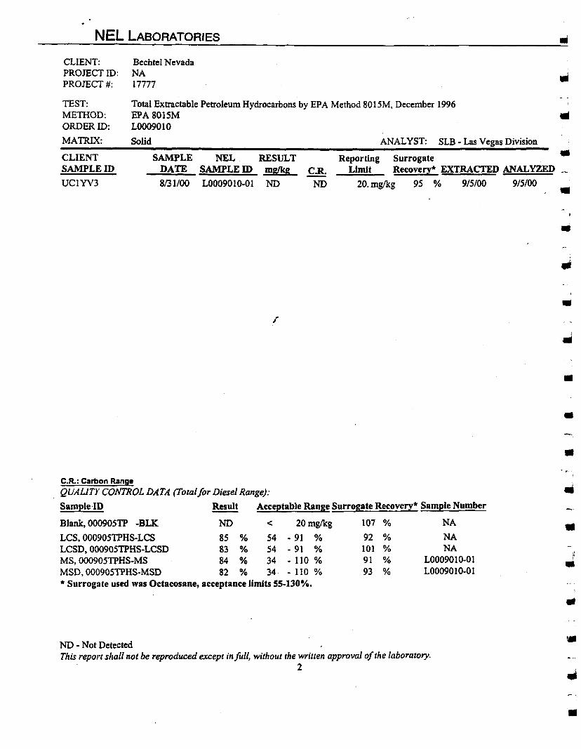
NEL LABORATORIES
Total Extractable Petroleum Hydrocarbons by EPA Method 80 ISM, December 1996EPA8015ML0009010
Solid ANALYST: SLB - Las Vegas Division
••
CLIENT:PROJECTID:PROJECT#:
TEST:METHOD:ORDERID:
MATRIX:
CLIENTSAMPLEID
UCIYV3
Bechtel NevadaNA17777
SAMPLEDATE
8/31/00
NELSAMPLEID
L0009010-0 1
RESULTmglkg
ND
r
CoR.ND
..Reporting Surrogate
Limit Recovery· EXTRACTED ANAL¥ZED ._
20. mg/kg 95 % 915100 915100
•,
•
••
•C.R.: Carbon Range
QUALiTY CONTROL DATA (Total for Diesel Range):
Sample·ID Result Acceptable Range Surrogate Recovery· Sample Number
Blank. 000905TP -BLK NO < 20mglkg 107 % NA
LCS.000905TPHS-LCS 85 % 54 - 91 % 92 % NALCSD. 000905TPHS-LCSD 83 % 54 - 91 % 101 % NAMS.00090STPHS-MS 84 % 34 - 110 % 91 % LOO09010-01MSD. 00090STPHS-MSD 82 % 34· - 110 % 93 % L0009010-0 1• Surrogate used was Octacosane, acceptance limits 55-130%.
••
ND - Not DetectedThis report shall not be reproduced except infull, without the written approval ofthe laboratory.
2
•
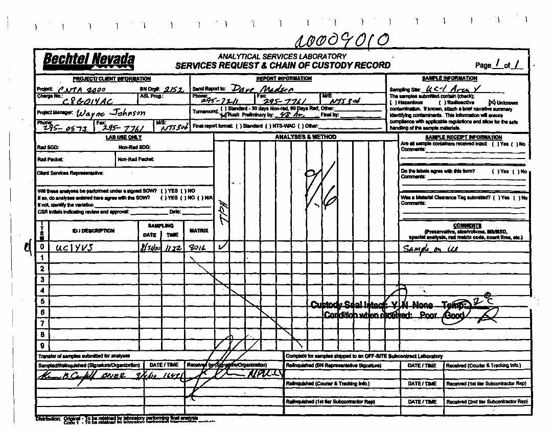
) 1 ) ) 1 ) 1 1
~
..~~ - . - ..Bechtel Nevada ANALYTlCAL SERVICES LASORATORY .
Page I «.I:SERVICES REQUEST & CHAIN OF CUSTODYRECORD .
PROJECT' CLIENT _ORMATION REPORT INFORMAJION IAI!'LE INFOIUIADO!
Pnllett .".AY1"A tUJ f) 0 8N 0rgIJ: .!l-K'1. send RIPaft tD: 1>411' AA~ "'..~" 8ImpIng SIll: tc c -I Arr"t, yICh8Ige NO.:~ ~ ~ ..... ,IAt: ASlProg.: Phone~_ 1 'LII .1FU~S_ ..,..,.,l/ 11n.iff,r ~.. TheumplellUbmIltId CIOIlI8fn (dleck);
EJl'YI '7 ~ , )HIurdous ( ) IWIollc:dve MUnllnown
PrajeclMInegir: 'WtLy 116 ..::r;,ltllt~nTumwaund: ( ) StIndIrd· 30 dlIyI~.IO;;::HM, Other: c:ontan*IaIIon. II kncNm, alIadt I briernarrative IUmmIIy
IdenIIryIng conIIrr*lIrda. ThIsInfannIIlon..eneura·~UIh PNIImkIaly~ n Final~
~ IFU lin: CamplIInce wIIh appIIcIIlIe regu\ItklnIlIIId IIIow far the life"f) ~- 4~"73 :J-fr- 771./ i/f$SpJ flnlllreport fDrmIt ( ) standanI ( ) NTS-WAC ( ) Other: handing c11he ..... maI8rl8II.
LABUSEOHLY ANALYSES & METHOD SAIFLE RECEIPT INFORMATION
RadSGD: Non-Rad 800:Ale II ..... COl........ receIYed IntacI ( ) Ves ( ) NoComrnanIs:
RadPlclcet INon-Rad Padcet
/CIIenl servtces RepI.......IIw: Vj Do thelIbeIIagreewIIh ItlI bm? ( )Ve. ( )NoCommenII:
... .
!~WI........be P81roimed under aligned saM t )YES ( ) NO r;1110, do IfIIIVIetenInd tin ..,..wlIh lie SOW? ( ) YES ( ) NO ( ) MfA
~weal MItIrIII CIeIIWQ Till eubntIed? ( ) Ves ( ) No
If not,Identify the Vlriallan Comrnenta:CSRInIIIIIIIndlcIIIng review and appRlVIII: • 0*:
t-:} SAIIPUNG COMMENT!. lID'DEICRPTION DATE" MAtRIX (PresIIYItIn, eIaIVoIume, IISIIISD•
......• naly.... rIId InItrIll code. counttime•••)
0 (,tc 1YVJ JhJl4Q J/2t- ~Olt. a/ ~~1M~ At. ia1 -,
,2 <,3 <,
4 ......:--..... ./ """ .'. .... .
5 <, - C!.18'- V v :111 .... - ~,1V--C.
6 - ~ .• -". PIV\F·~ ._. J ~j"- wi! Dft
7 ...... .., ..\..:../" ~I'...
8 ..... h v, . <,..9 V '/ / '\
TrInIfIr cI umplellUbmIlted for..... //J / CcmpIete for.....1hIppId to III OFF-IITE IubccIfterIct LabonIIaty
~ (S1gIlllLn/'Ol'pnlZ) DAle/DE .-.... ) ReInquiIIIed (IN RepruenCdwt SIgnItura) DAle/DIE ReceIVed (COUrier &Traddng Info.)
.I: Jf /!._ j~~/ A •._" . ~ L It."",' J Y;-l. ~. ',L \.-lU.r
/ "-1/ RIInquIIhed (CourIer. TrDlng 1nI!).) DATE/TIME ReceIVed (1sttierSUbconlnIdar Rep)
rReInquIIIled (1,t .... Wlc:onncD Rep) DATE/DIE ReceIved (2nd tierSubconlnldat Rep)
'~:f~ I~_......a..
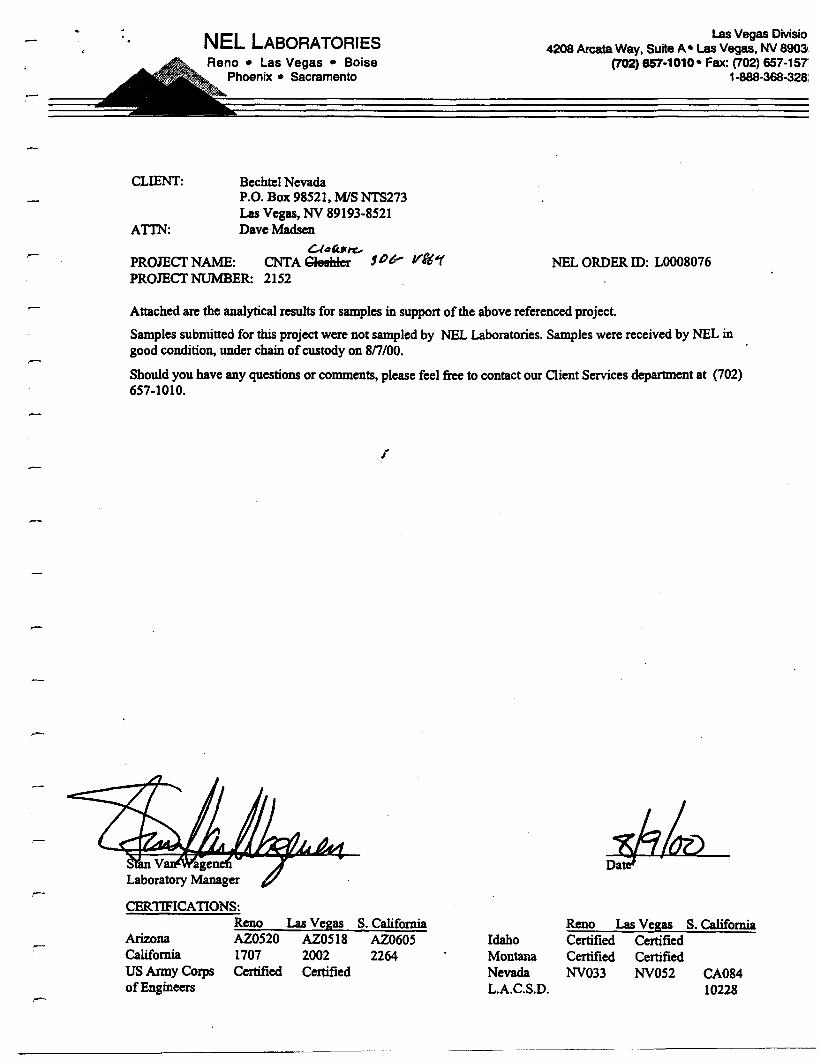
NEL LABORATORIESReno • Las Vegas • Boise
Phoenix • Sacramento
CLIENT: BechtelNevadaP.O. Box 98521, MIS NTS273Las Vegas,NV 89193-8521
ATIN: DaveMadscnCA~b/"C..-
PROJECTNAME: CNTACleshlel 106' ytt#fPROJECTNUMBER: 2152
Las Vegas Divisiol4208 Arcata Way, Suite A· Las Vegas, NV 89031
(702) 657-1010· Fax: (702) 657·1571-888-368-328:
NEL ORDER10: LOOO8076
.-
'Attachedarc the analyticalresults for samplesin supportof the above referencedproject.
Samplessubmitted for this project were not sampledby NEL Laboratories. Sampleswere receivedby NEL ingood condition,under chain of custodyon 8n/OO.
Should you have any questionsor comments, please feel free to contact our Client Servicesdepartmentat (702)657-1010.
CERTIFICAnONS:Reno Las Vegas
ArizonaCaliforniaUS Army Corpsof Engineers
AZ0520 AZ05181707 2002Certified Certified
S. CaliforniaAZ060S2264
IdahoMontanaNevadaL.A.C.S.D.
Reno Las Vegas S. CaliforniaCertified CertifiedCertified CertifiedNV033 NVOS2 CA084
10228

C.R.: Carbon RangeQUAUTY CONTROL DATA (Totalfor Diesel Range):
Sample ID Result Acceptable Range Surrogate Recovery· Sample Number
Blank, 000807TP -BLK. ND < 20 mglkg
LCS, 000807TPHS-LCS 77 % S4 - 91 %LCSD, 000807TPHS-LCSD 73 % S4 - 91 %• Surrogate used was Octacosane, acceptance limits 55-130%.
83 %81 %93 %
NA
NANA
••..
••
•NO - Not DetectedThis report shall not be reproduced except in full, without the written approval ofthe laboratory.
2
•III
•
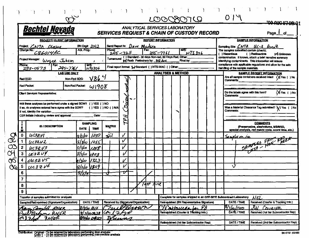
'1 1 I I ) '1 1 1 t I \1 1 'J J 1 ) I l
~'J. ~Q)s:;rsQ)1 <o 01 '\'00 AUg 01QR:Ql
Bechtel /(IfBJf ANALYTICAL SERVICES LABORATORYPage_'of_,SERVICES REQUEST& CHAIN OF CUSTODY RECORD
ProlectManaaer: I. '1tIL J.k(~
r"Z95-0573 IFax:;1.{/5-7/&1
1
1~~l306
REPORTINEORMADON
~~ro: DA~ ~,~
2A"-7~1/ j:ax59;:-21" ItNSpIs30'• T 00' ( ) Standard· 30 days Non-rad, 60 DaysRad, Other: _
umarou 'HRush Preliminary by: "f6r1 Rnalby:
RnaI report rorrnat: )¥Standard ( ) NTS·WAC ( ) Other:
Will theseanalyses be performed undera signed SOW? () VES ( ) NOIf so, do analysesentered hereagreewiththe SOW? ( ) VES ( ) NO ( ) NlAIf not,Identifythe Yaria!lon _
CSRinitialsindicating review andapproval: Date: _
CHent servicesRepresentative: ¥ves ( )No
\J
<.~ p '::;fh .....'~ ......~_~_~<--i ~ ~1',v~
COMMENTS(P.....rv8tlve. alzelvolume, MSlMSD,
apectal analysla, red matrix code, count time, etc.)
--or
Dothe labelsagreewiththisIorm?Comments: _
SAMPLERECEIPT INFORMADONAreansample containers received in!act ~Ves ( ) NoComments: _
Wasa Material Clearance Tag submilted? 'tV) Ves ( ) NoComments: .".--------------."
t11 ~., ...( ~,~"::t:
~I
ANALYSEB II METHOD
if'
"
//
tIt/
-VI - I 1/
v7'7
~il
....
MMRIXSAMPUNG
DATE I DME
~/~ I/S()9J •
13/~/.x
15/J!.xJ t.:lQ3'fhi» /3.2..3
Non-Rad SOG: V8' c../INon-Rad Packet: tU ICf08'
LAB USE ONLY
ID'DESCRIPT10N
UC32.V(
U{:n.vZUc~~113
uc.3:Z 1/6
¢3i!l/f.
d~32.:Vr
5
6
TTEM
RadPackeI:
RadSGD:
~4
61J!-W_ 1
2
No
~.0:)
crtt:iS
7 /8
9
1774¥ t1'rte7
Transferof samplessubmitted for analyses Complete forsamplesshippedto an OEE-8ITE Subcontract Laboratory Ait:1.Relinquished (BNRepresentative SIgnature) I DATEI TIME I Received (Courier& Tracking Info.)
TI\-rA1iitInLi~~ -9Jr-- - l'ih1m J'''tm I,'RAJ f /'I" A I r:;'D
Relinquished (Courier& TIr'cldng IntO,) I 6Alt/TIME I Received (1st tierSubcontractor Rep)
SampleO'Relinquished (Signature.Qganlza!lon)
.k.... . _ '~.._., L// .-.
o~.JI~L-:'oJ R1\1EI!.~j""J,.L.,/ ~ 61h.A,
DATE, TIME I Received by (SIg!!8lurelOrganizatlon)
~hk/616 l~j.A1~
l~h/()t1tJA3.8 IQJ., 1'-'· k.A9~~~I nA?:.~~_~
7 Relinquished (1st tier Subcontraetor Rep) DATE'TlME I Received (2nd tier Subcontractor Rep)
,: Qriglna~o be retalrilld J)ylaboratory~ final ina~~ l ·l~!!! !!!!!~ ~ '!'~,~ __ 9"I1li . Jnl8J'!lllldiilteanalysia
BN-ll732 (02J98)
CLIENT:
ATI'N:
NEL LABORATORIESReno. Las VegasPhoenix. Boise
Bechtel NevadaP.O. Box 98521, MIS NTS273Las Vegas, NV 89193-8521Ted Redding
Las Vegas Division4208 Arcata Way, Suite A • Las Vegas, Nevada 89030
702·657-1010. Fax: 702-657-15771-888-368-3282
PROJECT NAME: NAPROJECT NUMBER: 17777
NEL ORDER ill: L0008188
--
Attached are the analytical results for samples in support of the above referenced project.
Samples submitted for thisproject were not sampled by NEL Laboratories. Samples were received by NEL ingood condition, under chain of custody on 8/17/00.
Should you have any questions or comments, please feel free to contact our Client Services department at (702)657-1010.
Sample UC4SVS has peaks below the reporting limit eluting in the Diesel/Oil range. The peaks do notresemble either Diesel or Oil.
AZ0520 AZ05181707 2002Certified Certified
Stan Van WagenenLaboratory Manager
CERTIFICATIONS:Reno
ArizonaCaliforniaUS Army Corpsof Engineers
La~ Ye~as S, CaliforniaAZ06052264
IdahoMontanaNevadaL.A.C.S.D.
~J/r- /SS/J-(,?Date :
Reno Las Ve~as S, CaliforniaCertified CertifiedCertified CertifiedNV033 NV052 CA084
10228
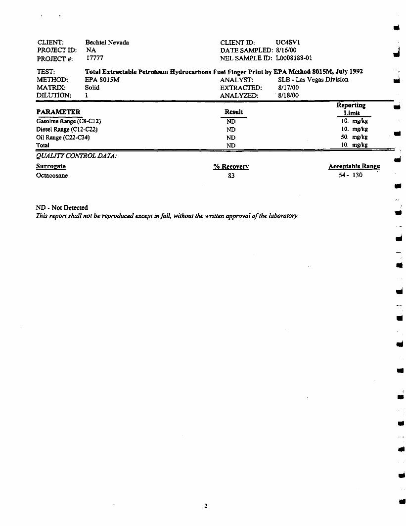
Total Extractable Petroleum Hydrocarbons Fuel Finger Print by EPA Method 801SM, July 1992EPA 8015M ANALYST: SLB - Las Vegas DivisionSolid EXTRACTED: 8117/001 ANALYZED: ·8/18/00
PARAMETER
Gasoline Range (C8-C12)Diesel Range (CI2-Cll)Oil Range (Cll-C34)Total
CLIENT:PROJECTID:PROJECT#:
TEST:METHOD:MATRIX:DILUTION:
Bechtel NevadaNA17777
CLIENT ill: UC4SVlDATE SAMPLED: 8/16/00NEL SAMPLE ill: L0008188-01
Result
NDNDNDND
ReportingLimit
10. mg/kg10. mglkg50. mglkg10. mg/kg
i.......
QUALITY CONTROL DATA:
Surrogate
Octacosane
0/0 Recovery
83
Acceptable Range
54- 130 ..NO - Not DetectedThis report shall not be reproducedexcept infull. withoutthe written approvalofthe laboratory.
2
..••..
II
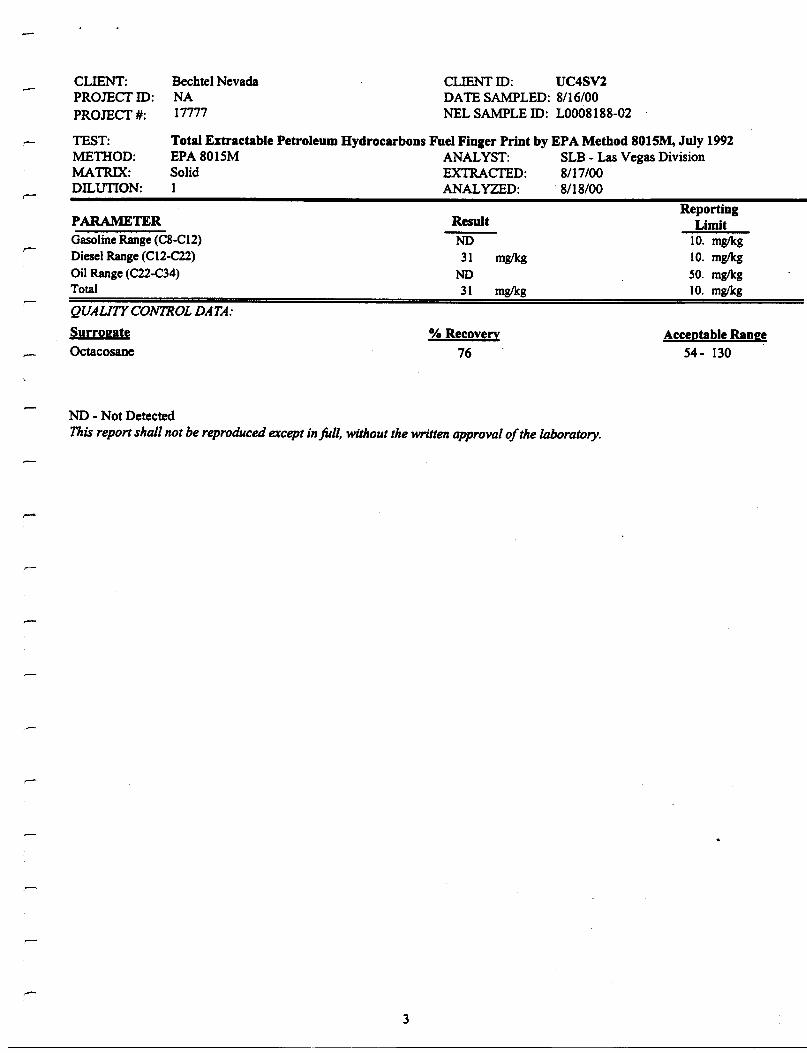
Total Extractable Petroleum Hydrocarbons Fuel Finger Print by EPA Method 8015M, July 1992EPA 8015M ANALYST: SLB - Las Vegas DivisionSolid EXTRACTED: 8/17/001 ANALYZED: 8/18/00
CLIENT:PROJECfID:PROJECf#:
TEST:MElHOD:MATRIX:DILUTION:
Bechtel NevadaNA17777
CLIENT ID: UC4SV2DATE SAMPLED: 8/16/00NEL SAMPLE ID: L0008188-02
PARAMETERGasoline Range (C8-CI2)Diesel Range (C12-C22)Oil Range (C22-C34)Total
QUAUTY CONTROL DATA:
Surrogate
Octacosane
Result
NO31 mg/kg
NO31 mglkg
% Recovery
76
ReportingLimit
10. mg/kg10. mglkg50. mglkg10. mglkg
Acceptable Range54- 130
NO - Not DetectedThis reportshall not be reproduced exceptinfull, withoutthe written approvalofthe laboratory.
3
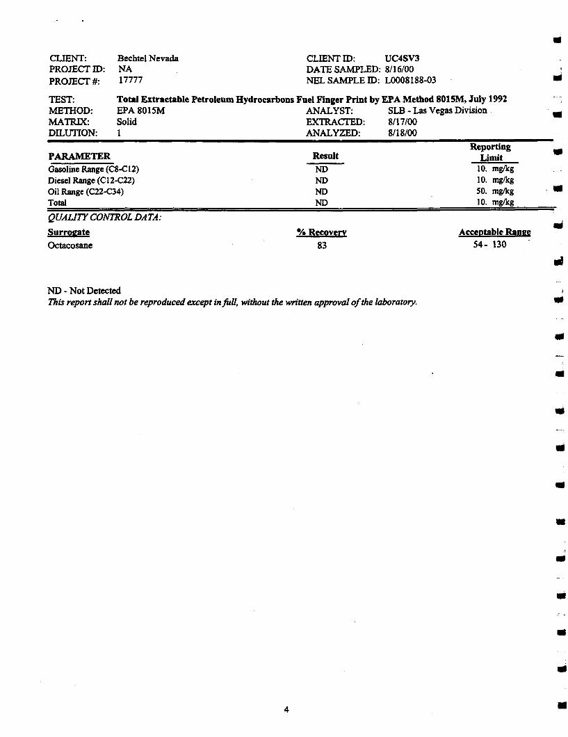
Total Extractable Petroleum Hydrocarbons Fuel Finger Print by EPA Method 8015M, July 1992EPA 8015M ANALYST: SLB - LasVegas DivisionSolid EXTRACI'ED: 8/17/001 ANALYZED: ·8/18/00
CLIENT:PROJECTID:PROJECT#:
TEST:METHOD:MATRIX:DILUTION:
Bechtel NevadaNA17777
CLIENT ID: UC4SV3DATE SAMPLED: 8/16/00NEL SAMPLE ID: L0008188-03
•
NO - Not DetectedThis report shall not be reproducedexcept inJUII, withoutthe written approvalofthe laboratory.
PARAMETERGasolineRange(C8-C12)Diesel Range (CI2-C22)Oil Range (C22-C34)Total
QUAliTY CONTROL DATA:
Surrogate
Octacosane
Result
NONONONO
% Recovery
83
ReportingLimit
10. mglkg10. mglkgSO. mglkg10. mglkg
Acceptable Range54- 130 .
III
III
..
•••••
I
••
..4 •

Total Extractable Petroleum Hydrocarbons Fuel Finger Print by EPA Method 801SM, July 1992EPA 8015M ANALYST: SLB - Las Vegas DivisionSolid EXTRACTED: 8/17/001 ANALYZED: 8/18/00
CLIENT:PROJECT 10:PROJECT#:
TEST:METIIOD:MATRIX:DILUTION:
Bechtel NevadaNA17777
CLIENT 10: UC4SV4DATE SAMPLED: 8/16/00NEL SAMPLE 10: LOOO8188-04
PARAMETERGasoline Range (C8-C12)Diesel Range (CI2-C22)Oil Range (C22-C34)Total
QUAUTY CONTROL DATA:
SurrogateOctacosane
ResultNONONONO
% Recovery
81
ReportingLimit
10. mglkg10. mglkgSO. mglkg10. mglkg
Acceptable Range54- 130
-
NO - Not DetectedThis report shall not be reproduced except in full, without the written approval ofthe laboratory.
5

Total Extractable Petroleum Hydrocarbons Fuel Finger Print by EPA Method 8015M, July 1992EPA 8015M ANALYST: 8LB - Las Vegas DivisionSolid EXTRACTED: 8/17/001 ANALYZED: 8/18/00
PARAMETERGasolineRange (CS-C12)DieselRange (C12-C22)Oil Range (C22-C34)Total
CLIENT:PROJECTID:PROJECT#:
TEST:METHOD:MATRIX:DILUTION:
Bechtel NevadaNA17777
CLIENT ID: UC4SV5DATE SAMPLED: 8/16/00NEL SAMPLE ID: LO008188-05
Result
NONONONO
ReportingLimit
'10. mglkg10. mg/kg50. mglkg10. mg/kg
..••
••QUAUTY CONTROL DATA:
Surrogate
Octacosane
% Recovery
85
Acceptable Range54- 130
NO - Not DetectedThis report shall not be reproducedexceptinfull. withoutthe written approvalofthe laboratory.
6
••11II
•........•11II
..
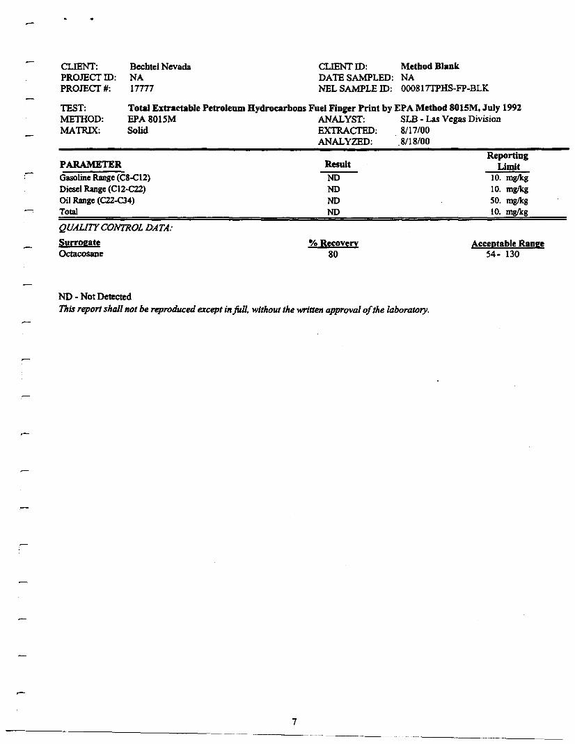
Total Extractable Petroleum Hydrocarbons Fuel Finger Print by EPA Method 801SM, July 1992EPA 80lSM ANALYST: SLB - Las Vegas DivisionSolid EXTRACTED: 8/17/00
ANALYZED: 8/18/00
CLIENT:PROJECfIO:PROJECf#:
TEST:MElHOD:MATRIX:
Bechtel NevadaNA17777
CLIENT 10: Method BlankDATE SAMPLED: NANEL SAMPLE 10: 000817TPHS-FP-BLK
PARAMETERGasoline Range(C8-C12)Diesel Range(CI2-C22)Oil Range (C22-C34)Total
QUAUTY CONTROL DATA:
SurrogateOctacosane
Result
NONONONO
-/0Recovery80
ReportingLimit
10. mg/kg10. mglkg50. mg/kg10. mglkg
Acceptable Range54- 130
,-
ND - Not DetectedThisreportshall not be reproducedexcept infull, withoutthe writtenapprovalofthe laboratory.
7
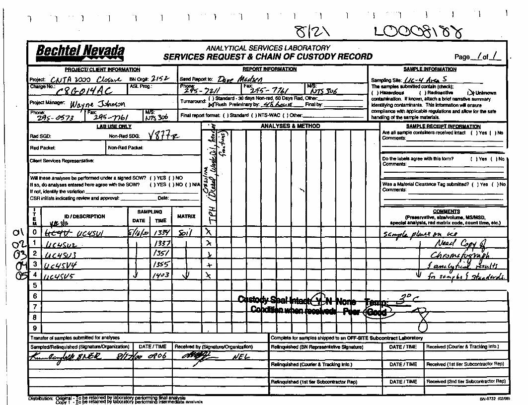
1 1 I 1 1 1
Bechtel Nevada ANALYTICAL SERVICES LABORATORYS!ERVICES REQUEST& CHAIN OF CUSTODY RECORD Page lof I.......................... .
PRQJECT! CLIENTINFORMATION REPQRTINfQRMATION SAMPlE INFORMADON
Project: "co/AliA 'l/.X)O ~k~ BNOfgl: '-,'5z- SendReportto: Ds~ .A"~d.v// saql!lngSlte: 1/,-1{ At!6 SChargeNo.: ,.~ I'~LJ,1/Ac: ASlProg.:
P'l;s-- '1,/1 FllX";i..7~_ 716/ I~yo.< The samplessubmiI!ed contain (check);{~Unlcnown( ) Haardous ( ) Rlldlolct!.
ProjectManager: Wo.~ n.f. ~~:7V\Turnaround: ( ) Standard· 30daysNon-rad, 60 DaysRad. Other. contaminallon. If known, attacha brief narrative SURVna'Y
)c(Rush Preliminary by: Utik,. IS final by: identifyingcontaminants. Thisinformation willensurePhone: I IFllX"j.J#t;-7?bl 1~3ob Finalreportlonna!: ( ) Standard ( ) NTS-WAC ( ) Other.
compliance with applicable regulations andallowfor the sale2IJS-~73 handlingof !he sa"1lle materials.
LAB USEONLY ''t ANALYSES & METHOD SAMPLE RECEIPT INFOBMADON
RadSGD: Non-Rad SOO: "~11<1t- -: .......) Areansample containers received Intact ( ) Yes ( )Nollij '.c- Comments:~ ...INon·Rad Packet: -: ~RadPacket: " oJ
i ~ClientServices Representative: Dothe labels agreewith!hIsform? ( ) Yes ( ) NoComments:
~WiU !heseanalyses be performed undera signedSOW? {)YES{)NO
~~If so,do analyses entered hereagreewiththeSOW? ( ) YES ( ) NO ( ) NlA Wasa Material Clearance Tag submitted? ( ) Yes ( ) No
If not. identifythe varlallon ..., Comments:
CSRinitialsindicating review and approval: Date:
I SAMPLING ::t. COMMENTST .9.1:~ /DESCRIPDON MATRIX r.: (P.....rv.tlve. slzelvolume.MSlMSD,E a II DATE DMEM specIe! .N1lysl., rIIdmatrix code, count tIme, etc.)
\ 0 / I ul i',1j~ I:J~ "iD1'l '>\ S&-.,,!.L J?~.HI kJ'«'-- 7 V tlC".s~
~ 1 IJt:I./~UL . 1311 ){,. •
/lJ~ (11Jt1 6. 1
~ 2 I~ C-I.ISUJ 1:sS'/ }. e;,,.~Au~~C ,l
~3 f.Jcl.l~Vtl /JS$' ~ f 4oM~lt..lJ jis~/lJ4 lu.t.I(l/~
,~ 1"1173 ,~ ~ \ I .(;, I~':"Lt f qJ.A""~VJ.r.-5
,
6 - a.....,1 .. ~ "a. ,. ':;l>~-7 - -"--~_. - -" B. ~ .~
'- _. ~8 • r- / v9 )
Transferof sa"1lles submitted lor analyses Complete lor samples shipped to an OFF-SITE Subcontract L.boratory
Sa"1lledlRelinqulshed (SignaturelOrganization) DATE/TIME Received by (SignaturelOrganizallon) ReInqul8hed (BNRepresentative Signature) DATEITIME Received (Courier& Tracking Inlo.)
.e: A. '-~~ ". JiT-b ~f'~ rou d!()b AIEl-u /' ReRnqulshed (Courier& Tracking Info.) DATEITIME Received (1st tier Subcontractor Rep)
Relinquished (1sttier SUbcontractor Rep) DATE/TIME Received (2nd tier Subcontractor Rep)
DistribUtion· Q~!ll - To be rela!neg !lY !8!Joratory==rnnal a~_s BN-ll732 1021981. '11, Io~ re!a!rMK! !JY ~bofa!ory ormno ntermediate analVRi..
ooo
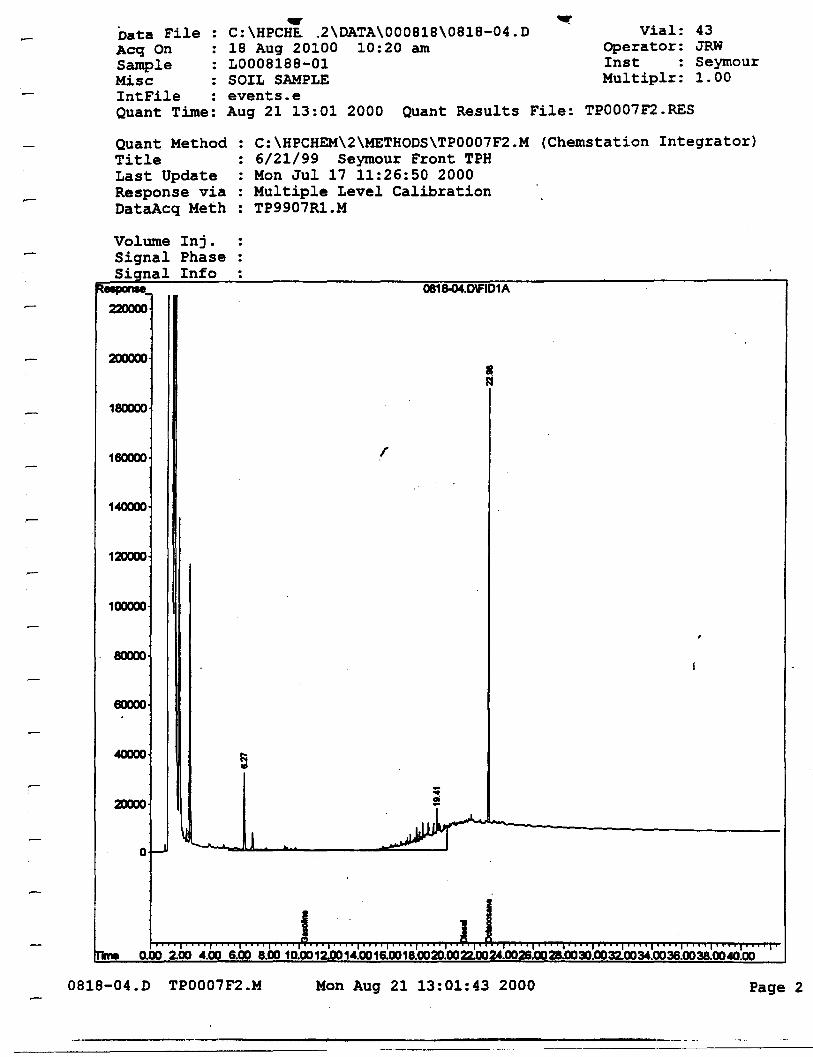
... ....Data File : c: \HPCHE.. .2\DATA\000818\0818-04.D Vial: 43Aeq On 18 Aug 20100 10:20 am Operator: JRWSample LOO08188-01 Inst SeymourMise : SOIL SAMPLE Multiplr: 1.00IntFile events.eQuant Time: Aug 21 13:01 2000 Quant Re.sults File: TPOO07F2.RES
Quant MethodTitleLast UpdateResponse viaDataAcq Meth
Volume Inj.Signal PhaseS.1.gnal Info
200000
180000
160000
1«XJOO
12DODO
100000
80000
60000
..
C:\HPCHEM\2\METHODS\TP0007F2.M (Chemstation Integrator)6/21/99 Seymour Front TPHMon Jul 17 11:26:50 2000Multiple Level CalibrationTP9907R1.M
0818-04.Dv:lD1A
r
«XJOO I:;.;
-•2DODO ai
A~o~
'- .. J
I I! 1 .1 1 -' 'I .' .1 ~I .1 ... 'I .1 ~l_ ~r :1 .1.
0.00 2.00 4.00 6.00 8.00 10.0012.0014.0016.0018.0020.0022.0024.0026.0028.0030.0032.0034.0036.0038.0040.00
0818-04.D TP0007F2.M Mon Aug 21 13:01:43 2000 Page 2
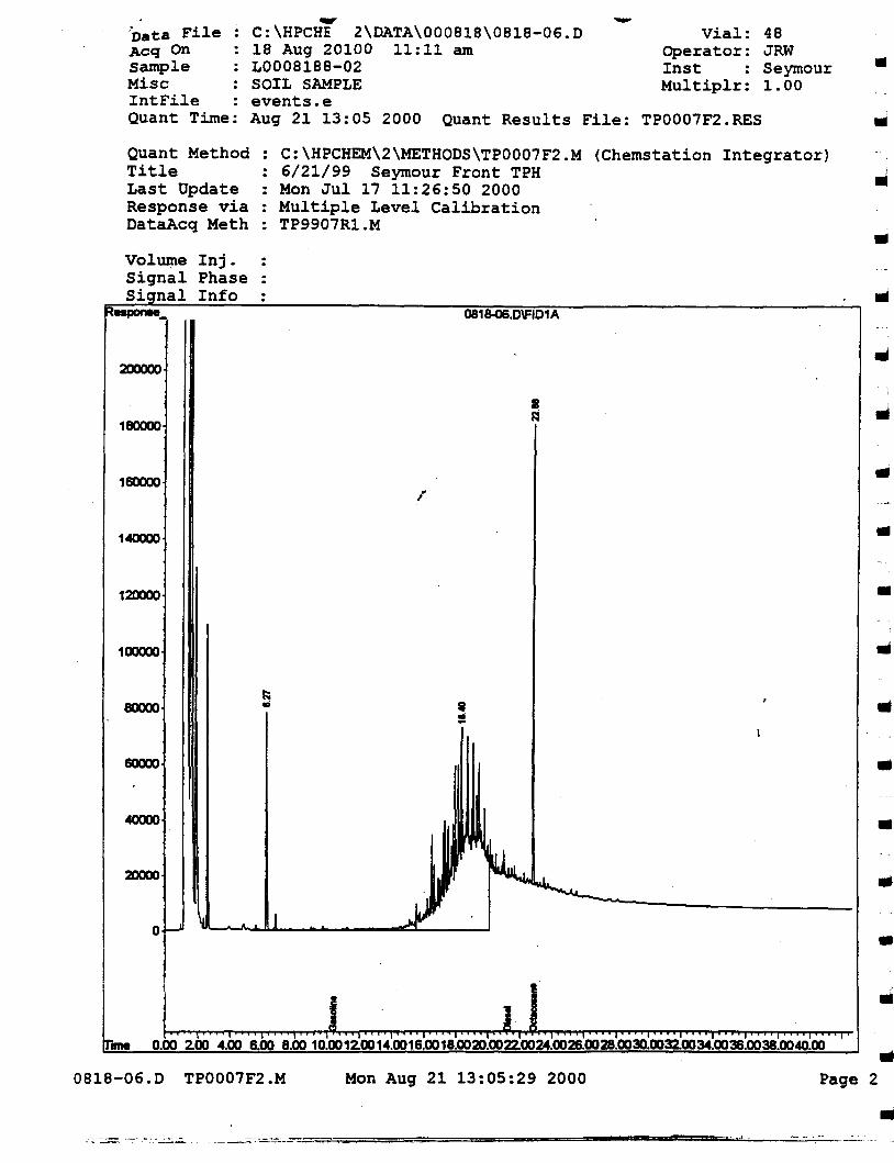
..48JRWSeymour1.00
Vial:Operator:InstMultiplr:
-...C:\HPCHE 2\DATA\000818\0818-06.D18 Aug 20100 11:11 amL0008188-02SOIL SAMPLEevents.eAug 21 13:05 2000 Quant Results File: TP0007F2.RES
'Data File :Acq OnSampleMiseIntFileQuant Time:
Quant MethodTitleLast UpdateResponse viaDataAeq Meth
Inj.PhaseInfo
C:\HPCHEM\2\METHODS\TP0007F2.M (Chemstation Integrator)6/21/99 Seymour Front TPHMon Jul 17 11:26:50 2000Multiple Level Calibration
: TP9907R1.M
0818-06.D\FJD1A
,•..Ii
200000
180000
160000r
III
140000 III
120000 •100000
..60000 ..
20000
o
•III
..I", I"""" 'I"""'" ,1..""" ,,,,,,,,,,,,,,,,,1,.1., I'" "" "I'" 'I' """"I""",,, I' "'1""1'
0.00 2.00 4.00 6.00 8.00 10.00 12.0014.0016.0018.0020.0022.0024.0026.0028.0030.0032.0034.0036.0038.0040.00me
0818-06.D TP0007F2.M Mon Aug 21 13:05:29 2000..
Page 2
•"'.,..t .--~'-_. ----- =============---====---_.....~_----:::.:.:..:;::.:-
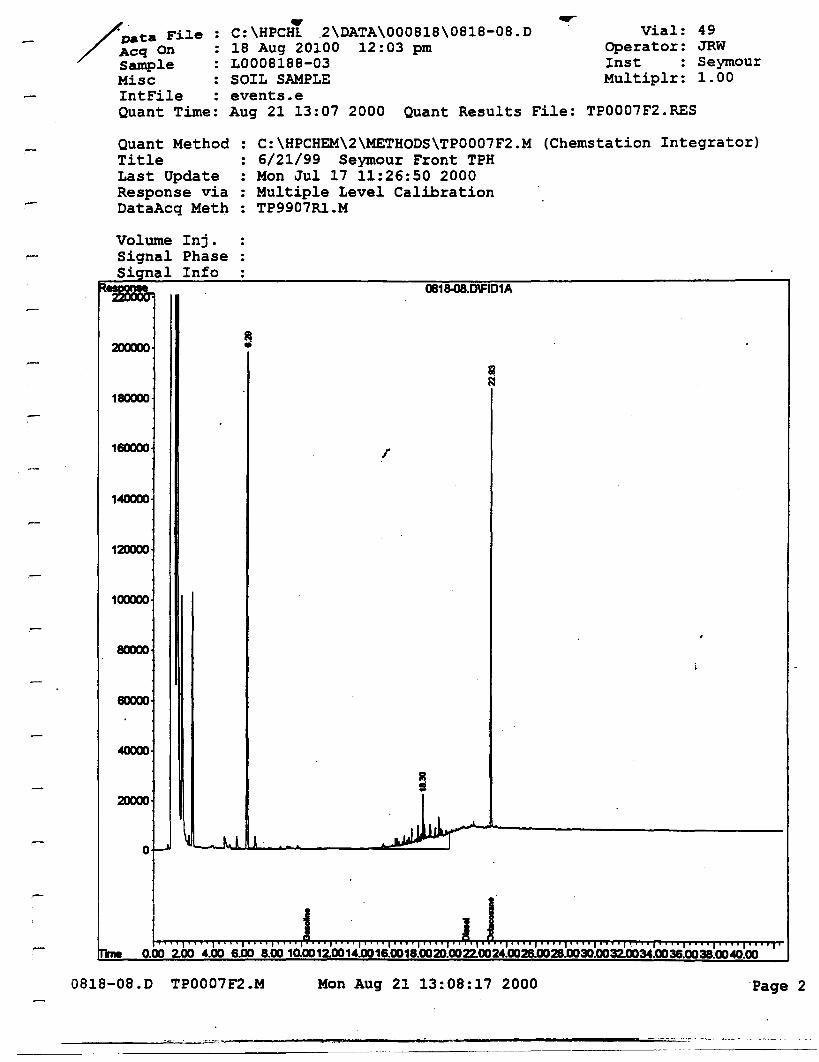
Quant Results File: TP0007F2.RES
/ ~ta Fil.e :/ ~Cq On :
sampl.e :MiseIntFile :Quant Time:
.,c: \HPCHl .2\ DATA\000818\0818-08. D18 Aug 20100 12:03 pmL0008188-03SOIL SAMPLEevents.eAug 21 13:07 2000
Vial:Operator:InstMultiplr:
49JRWSeymour1.00
Quant MethodTitleLast UpdateResponse viaDataAeq Meth
C:\HPCHEM\2\METHODS\TP0007F2.M6/21/99 Seymour Front TPH
: Mon Jul 17 11:26:50 2000Multiple Level CalibrationTP9907Rl.M
(Chemstation Integrator)
Volume Inj.Signal PhaseSignal Info
0818-08.D\FID1A
200000
180000
160000 r
1«XXJO
12000D
100000
80000
60000
2000D
of.-J ~ l 1 ~~~'-------
TmeI"" I"" 0"" I"" i"" J." I"" I"" I"" I"" I',J,,;'" I"" 1'" '1"" I"" I"" I"" I"" I"" I'
0.00 2.00 4.00 6.00 8.00 10.0012.0014.0016.0018.0020.0022.0024.0026.0028.0030.0032.0034.0036.0038.0040.00
DB1B-OB.D TP0007F2.M Mon Aug 21 13:08:17 2000 'Page 2
m----_........--_......_---------..........=.._=...'-=...•.. _. -.-.- .. -_._--
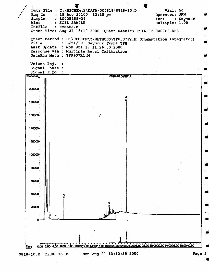
•
•
•..
50JRWSeymour1.00
Vial:Operator:lnstMultiplr:
"
(Chemstation Integrator)
..
: C:\HPCHEM\2\METHODS\TP0007F2.M6/21/99 Seymour Front TPHMon Jul 17 11:26:50 2000
: Multiple Level CalibrationTP9907R1.M
•C:\HPCH~\2\DATA\000818\0818-10.D
18 Aug 20100 12:55 pmL0008188-04SOIL SAMPLEevents.eAug 21 13:10 2000 Quant Results File: TP0007F2.RES
Data FileAeq OnSampleMiselntFileQuant Time:
Quant MethodTitleLast UpdateResponse viaDataAeq Meth
Volume Inj.Signal PhaseSignal Info
0818-10.D\FID1A
2DOOOO
1BOOOO ..160000 I'
IIIlI140000 ..120000
..100000
..80000
•BOOOO
..20000
l;.t
. .I~~:!II&~--- ---oJ \t..'- ...u...L. ---eL=::::jJJJ'~----I-1
..•
Ir....I.··,i •••• , •• • , , ' ••• , ' ••• ,I...,....,'...,.... I ' ... , •1,·I·,·..·I • • • , I' • , • I • • • • , • • • , I • • • • , • • • • I ' , , • I • • • • I '
0.00 2.00 4.00 6.00 8.00 10.0012.0014.0016.0018.0031.0022.0024.0026.0028.0030.0032.0034.0036.0038.0040.00 ..0818-10.D TP0007F2.M Mon Aug 21 13:10:59 2000 Page 2'
••
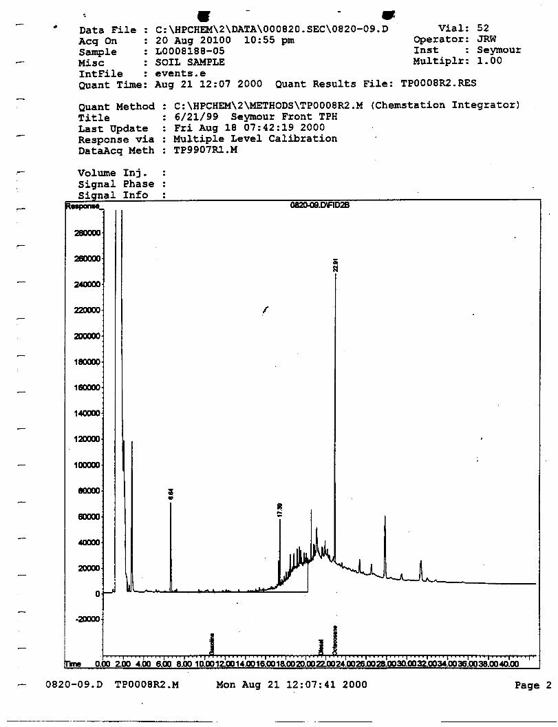
52JRWSeymour1.00
Vial:Operator:Inst :Multiplr:
• •C:\HPCHEM\2\DATA\000820.SEC\0820-09.D20 Aug 20100 10:55 pmL0008188-05 .SOIL SAMPLEevents.eAug 21 12:07 2000 Quant Results File: TP0008R2.RES
Data FileAeq OnSampleMiseIntFile :Quant Time:
Quant MethodTitleLast UpdateResponse viaDataAeq Meth
: C:\HPCHEM\2\METHODS\TP0008R2.M6/21/99 Seymour Front TPH
: Fri Aug 18 07:42:19 2000Multiple Level CalibrationTP9907Rl.M
(Chemstation Integrator)
Volume Inj.Signal PhaseS~cJnal Info
082Q.09.O\FID2B
280000
220000
200000
160000
1040000
120000
100000
80000
60000
2QOCIO
o~
.2QOCIO
L .:00 2.lXl ..00 ..00 ..00 ,J'ilXl....lIl'• .llO'..lXI20m!...24.l10211.l1028.lXI3l1.llll0i0034:lXI3B.D11..:lXI~lXI '
0820-09.D TP0008R2.M Mon Aug 21 12:07:41 2000 Page 2
NEL LABORATORIESReno • Las VegasPhoenix. Boise
Las Vegas Division4208 Arcata Way, Suite A • Las Vegas. Nevada 89030
702-657-1010. Fax: 702-657-15771-888-368-3282
CLIENT:
ATI'N:
Bechtel NevadaP.O. Box 98521, MIS NTS273Las Vegas, NY 89193-8521Ted Redding
PROJECT NAME: V881PROJECT NUMBER: 17777
NEL ORDER ill: L0008264
Attached are the analytical results for samples in support of the above referenced project.
Samples submitted for this project were not sampled by NEL Laboratories. Samples were received by NEL ingood condition, under chain of custody on 8/23/00.
Should you have any questions or comments, please feel free to contact our Client Services department at (702)657-1010.
Reno Las Ve2as S. CaliforniaCertified CertifiedCertified CertifiedNY033 NV052 CA084
10228
IdahoMontanaNevadaL.A.C.S.D.
AZ06052264
S. CaliforniaLas Ve2asAZ0520 AZ05181707 2002Certified Certified
ArizonaCaliforniaUS Army Corpsof Engineers
fA.' ./~. )'1/ /J//11';' //;, /' /,~,1«£ ~ 'fi4~ .tp"./l
Stan Van Wagenen .' /'Laboratory Manager "
CERTIFICATIONS;Reno

Total Extractable Petroleum Hydrocarbons Fuel Finger Print by EPA Method 801SM, July 1992EPA 8015M ANALYST: JRW - Las Vegas DivisionSolid EXTRACTED: 8/23/001 ANALYZED: ·8/24/00
CLIENT:PROJECTID:PROJECT#:
TEST:METHOD:MATRIX:DILUTION:
Bechtel NevadaV88117777
CLIENT ID: UC4SV6DATE SAMPLED: 8/22/00NEL SAMPLE ID: L0008264-01
•Reporting
PARAMETER Result LimitGasoline Range (CS-e12) NO 10. mglkgDiesel Range (CI2-Cn) NO 10. mglkg
Oil Range (Cn-e34) SO mglkg SO. mglkg ••Total SO mg/kg 10. mg/kg
QUALITY CONTROL DATA: ..Surrogate % Recovery Acceptable Range
Octacosane 75 54- 130
ND - Not DetectedThis report shall not be reproduced except in full. without the written approval ofthe laboratory.
••II
III
..
..III
..II
2 III
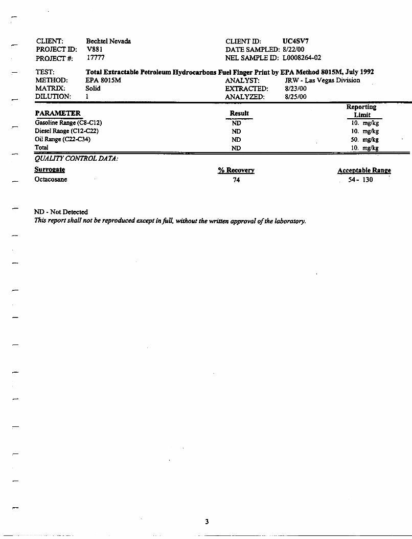
Total Extractable Petroleum Hydrocarbons Fuel Finger Print by EPA Method 8015M, July 1992EPA 8015M ANALYST: JRW - Las Vegas DivisionSolid EXTRACTED: 8/23/001 ANALYZED: . 8/25/00
CLIENT:PROJECTID:
PROJECT#:
TEST:MElHOD:MATRIX:DILUTION:
Bechtel NevadaV88117777
CLIENT ID: UC4SV7DATE SAMPLED: 8/22/00NEL SAMPLE ID: L0008264-02
,-
ReportingPARAMETER Result LimitGasolineRange(CS-e12) NO 10. mglkgDieselRange (C12-e22) NO 10. mglkgOil Range(C22-C34) NO SO. mglkgTotal NO 10. mglkg
QUAUTY CONTROL DATA:
Surrogate % Recoverv Acceptable RangeOctacosane 74 54- 130
NO - Not DetectedThisreportshall not be reproducedexceptinfull. without the writtenapprovalofthe laboratory.
3
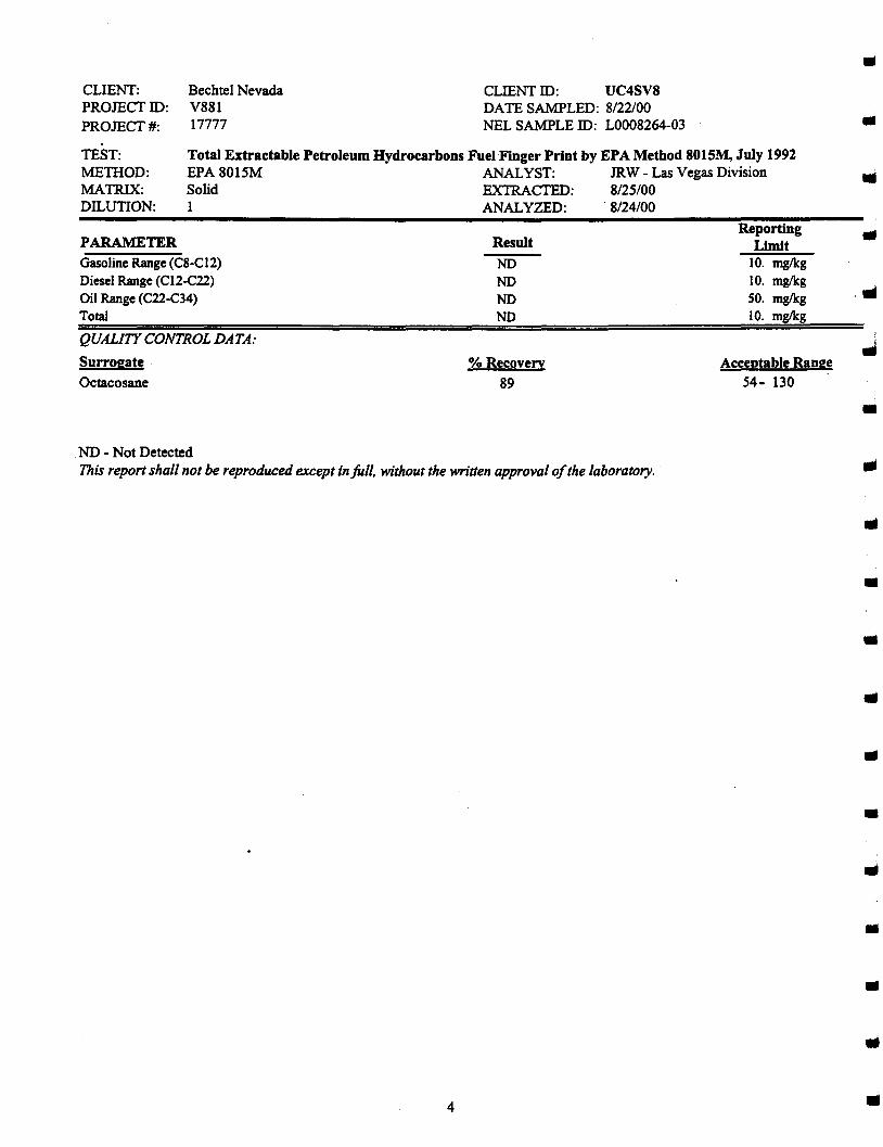
Total Extractable Petroleum Hydrocarbons Fuel Finger Print by EPA Method 8015M, July 1992EPA 8015M ANALYST: JRW - Las Vegas DivisionSolid EXTRACTED: 8/25100I ANALYZED: 8/24/00
PARAMETER
Gasoline Range (C8-CI2)Diesel Range (CI2-C22)Oil Range (C22-C34)Total
CLIENT:PROJECTID:PROJECT#:
TEST:METIlOD:MATRIX:DILUTION:
Bechtel NevadaV88117777
CLIENT ID: UC4SV8DATE SAMPLED: 8/22100NEL SAMPLE ID: L0008264-03
Result
NONONONO
ReportingLimit
10. mglkg10. mglkg50. mglkg10. mglkg
..
III
.....
QUALITY CONTROL DATA:
Surrogate
Octacosane% Recovery
89
Acceptable Range54- 130
III
NO - Not DetectedThis reportshall not be reproducedexcept infull. withoutthe written approvalofthe laboratory.
4
..III
..
..
..III
..
..•....•
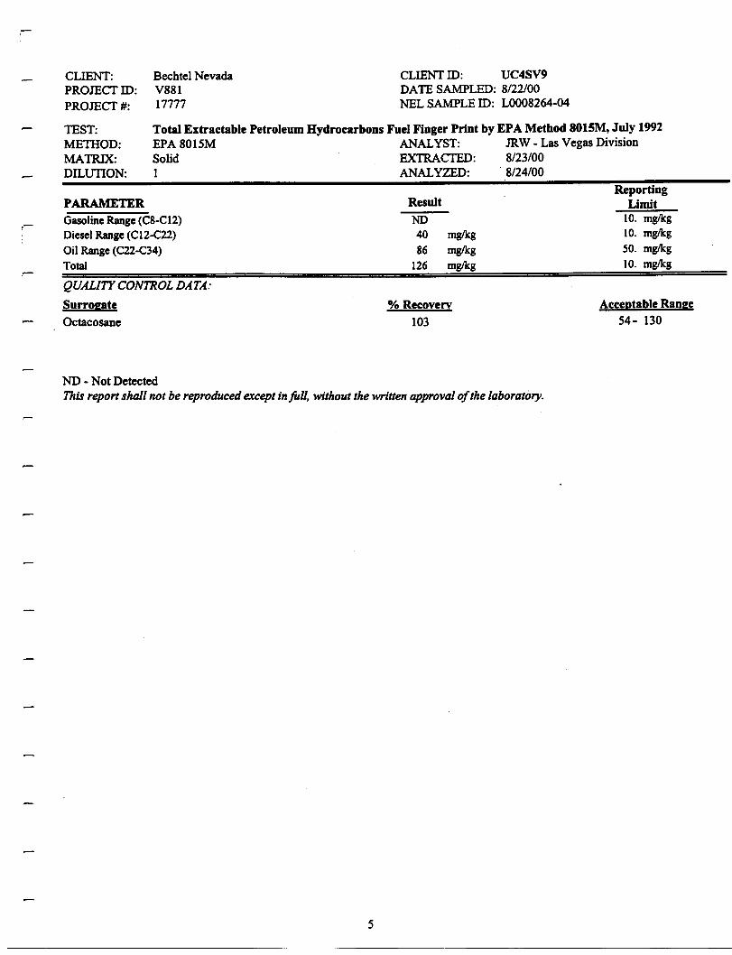
Total Extractable Petroleum Hydrocarbons Fuel Finger Print by EPA Method 801SM, July 1992EPA 8015M ANALYST: JRW - Las Vegas DivisionSolid EXTRACTED: 8/23/001 ANALYZED: . 8/24/00
CLIENT:PROJECT 10:PROJECT#:
TEST:METHOD:MATRIX:DILUTION:
Bechtel NevadaV88117777
CLIENT 10: UC4SV9DATE SAMPLED: 8/22/00NEL SAMPLE 10: L0008264-04
,-
PARAMETERGasoline Range (C8-CI2)Diesel Range (C12-C22)Oil Range (C22-C34)Total
Result
NO4086
126
mg/kgmg/kgmg/kg
ReportingLimit
10. mg/kg10. mg/kgSO. mg/kg10. mg/kg
QUAUTY CONTROL DATA:
Surrogate
Octacosane
% Recovery
103
Acceptable Range54- 130
ND - Not DetectedThis report shall not be reproduced except inJUII. without the written approval ofthe laboratory.
5

Total Extractable Petroleum Hydrocarbons Fuel Finger Print by EPA Method 801SM,July 1992EPA 8015M ANALYST: JRW - Las Vegas DivisionSolid EXTRACTED: 8/23/001 ANALYZED: . 8/24/00
CLIENT:PROJEcrID:PROJEcr#:
TEST:METHOD:MATRIX:DILUTION:
Bechtel NevadaV88117777
CLIENTID: UC4SVI0DATE SAMPLED: 8/22/00NEL SAMPLE ID: LOOO8264-05
IIIl
III
PARAMETERGasoline Range (C8-CI2)Diesel Range (CI2-C22)Oil Range (C22-C34)Total
QUAUTY CONTROL DATA:
Surrogate
Octacosane
ResultNONONONO
% Recovery
68
ReportingLimit
10. mglkg10. mglkgSO. mglkg10. mglkg
Acceptable Range54- 130
...
NO - Not DetectedThis reportshall not be reproducedexcept in full, withoutthe written approvalofthe laboratory.
6
..•
..
..III
..•
•
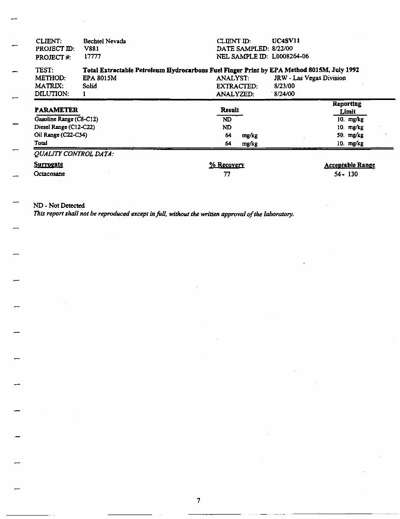
Total Extractable Petroleum Hydrocarbons Fuel Finger Print by EPA Method 8015M, July 1992EPA 8015M ANALYST: JRW - Las Vegas DivisionSolid EXTRACTED: 8/23/00I ANALYZED: ·8/24/00
CLIENT:PROJECI'ID:PROJECI'#:
TEST:METHOD:MATRIX:DILUTION:
Bechtel NevadaV88117777
CLIENT ID: UC4SVllDATES~LED:8a2rooNELS~LE ID: L0008264-06
PARAMETERGasolineRange (C8-CI2)Diesel Range (CI2-C22)Oil Range (C22-C34)
Total
Result
NDND6464
mg/kg
mg/kg
ReportingLimit
10. mg/kg10. mg/kgSO. mg/kg
10. mg/kg
QUAliTY CONTROL DATA:
Surrogate
Octacosane
% Recovery
77Acceptable Range
54- 130
,-
ND - Not DetectedThis report shall not be reproduced except in full, without the written approval-ofthe laboratory.
7
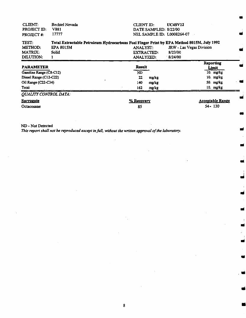
Total Extractable Petroleum Hydrocarbons Fuel Finger Print by EPA Method 801SM, July 1991EPA 8015M ANALYST: JRW - Las Vegas DivisionSolid EXTRACTED: 8/23/00I ANALYZED: . 8/24/00
CLIENT:PROJECfIO:PROJECf#:
TEST:METIIOD:MATRIX:DILUTION:
Bechtel NevadaV88117777
CLIENT 10: UC4SV12DATESANWLED: 8~2roO
NEL SAMPLE 10: LOO08264-07
•
..Reporting
PARAMETER Result LimitGasoline Range (C8-CI2) NO 10. mglkgDiesel Range (CI2-C22) 22 mg/kg 10. mglkgOil Range (C22-e34) 140 mg/kg 50. mglkg .l1li
Total 162 mg/kg 10. mglkg
QUALITYCONTROL DATA: IIISurrogate % Recoverv Acceptable Range
Octacosane 8S 54- 130
•NO - Not DetectedThis report shall not be reproduced except in full, without the written approval ofthe laboratory.
l1li
•
l1li
l1li
•
. "
8 •
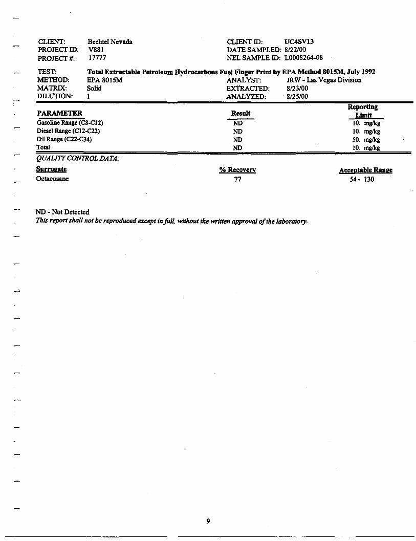
Total Extractable Petroleum Hydrocarbons Fuel Finger Print by EPA Method 801SM, July 1992EPA 8015M ANALYST: JRW - Las Vegas DivisionSolid EXTRACTED: 8/23/00I ANALYZED: . 8/25100
CLIENT:PROmeI'ID:PROmeI'#:
TEST:METIIOD:MATRIX:DILUTION:
Bechtel NevadaV88117777
CLIENT 10: UC4SV13DATE SAMPLED: 8/22/00NEL SAMPLE 10: L0008264-08
PARAMETERGasoline Range (C8-C12)Diesel Range (C12-C22)Oil Range (C22-C34)Total
QUAUTY CONTROL DATA:
SurrogateOctacosane
Result
NONONONO
0/0 Recovery77
ReportingLimit
10. mg/kg10. mglkgSO. mg/kg10. mg/kg
Acceptable Range54- 130
-
ND - Not DetectedThis report shall not be reproduced except in full. without the written approval ofthe laboratory.
9
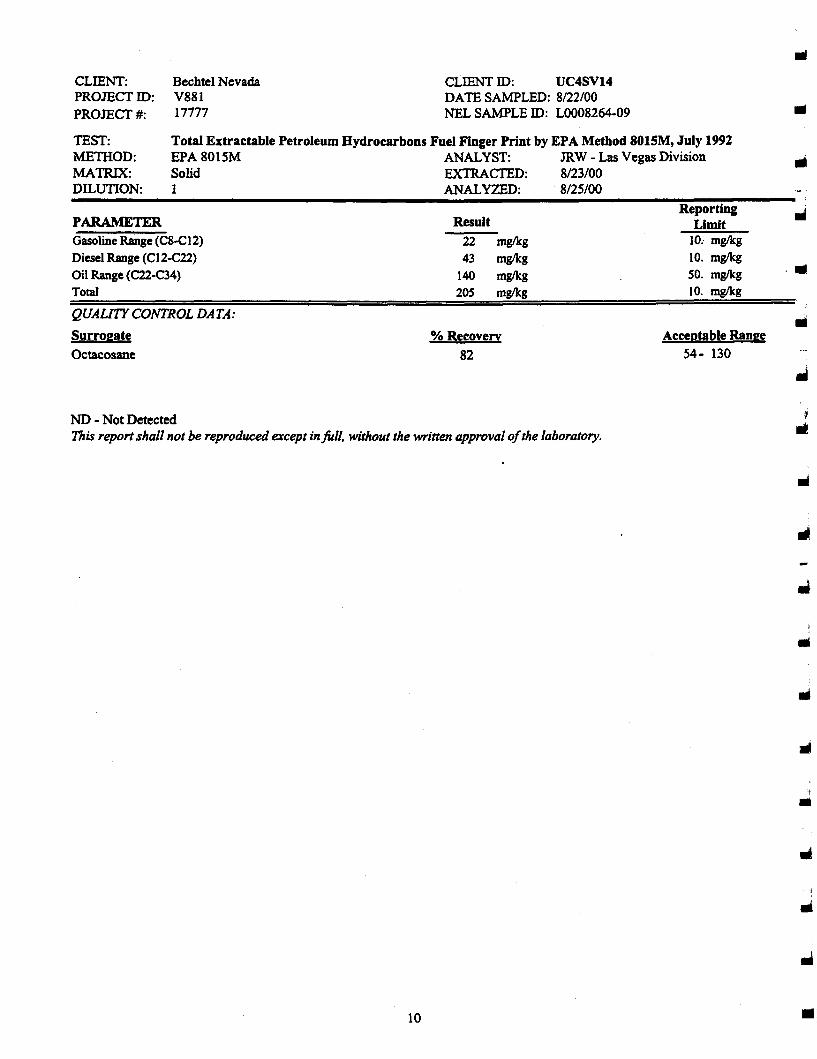
Total Extractable Petroleum Hydrocarbons Fuel Finger Print by EPA Method 8015M, July 1992EPA 8015M ANALYST: JRW - Las Vegas DivisionSolid EXTRACTED: 8/23/001 ANALYZED: . 8/25/00
CLIENT:PROJEcrID:PROJEcr#:
TEST:METHOD:MATRIX:DILUTION:
Bechtel NevadaV88117777
CLIENT ID: UC4SV14DATESANWLED: 8n2rooNEL SAMPLE 10: L0008264-09
III
III
PARAMETERGasoline Range (C8-C12)
Diesel Range (CI2-C22)
Oil Range (C22-C34)
Total
QUALITY CONTROL DATA:
Surrogate
Octacosane
Result
22 mglkg
43 mg/kg
140 mg/kg
205 mglkg
% Recovery
82
ReportingLimit
10.. mglkg
10. mg/kg
50. mglkg
10. mglkg
Acceptable Range
54- 130
.111
ND - Not DetectedThis report shall not be reproduced except in full. without the written approval ofthe laboratory.
10
..
t
•
..

Total Extractable Petroleum Hydrocarbons Fuel Finger Print by EPA Method 801SM, July 1992EPA 8015M ANALYST: JRW - Las Vegas DivisionSolid EXTRAcrED: 8/25/001 ANALVZED: . 8/25/00
CLIENT:PROJEcrID:PROJEcr#:
TEST:ME1HOD:MATRIX:nrurnos.
Bechtel NevadaV88117777
CLIENT ID: UC4SVISDATE SAMPLED: 8/22/00NEL SAMPLE ID: L0008264-10
PARAMETERGasolineRange(C8-C12)Diesel Range(CI2-C22)Oil Range (C22-C34)Total
QUAUTY CONTROL DATA:
Surrogate
Octaeosane
Result
NONONONO
% Recovery
97
ReportingUmit
10. mg/kg10. mg/kgSO. mg/kg10. mglkg
Acceptable Range54- 130 .
NO - Not DetectedThisreportshall not be reproducedexceptinfull, withoutthe writtenapprovalofthe laboratory.
11
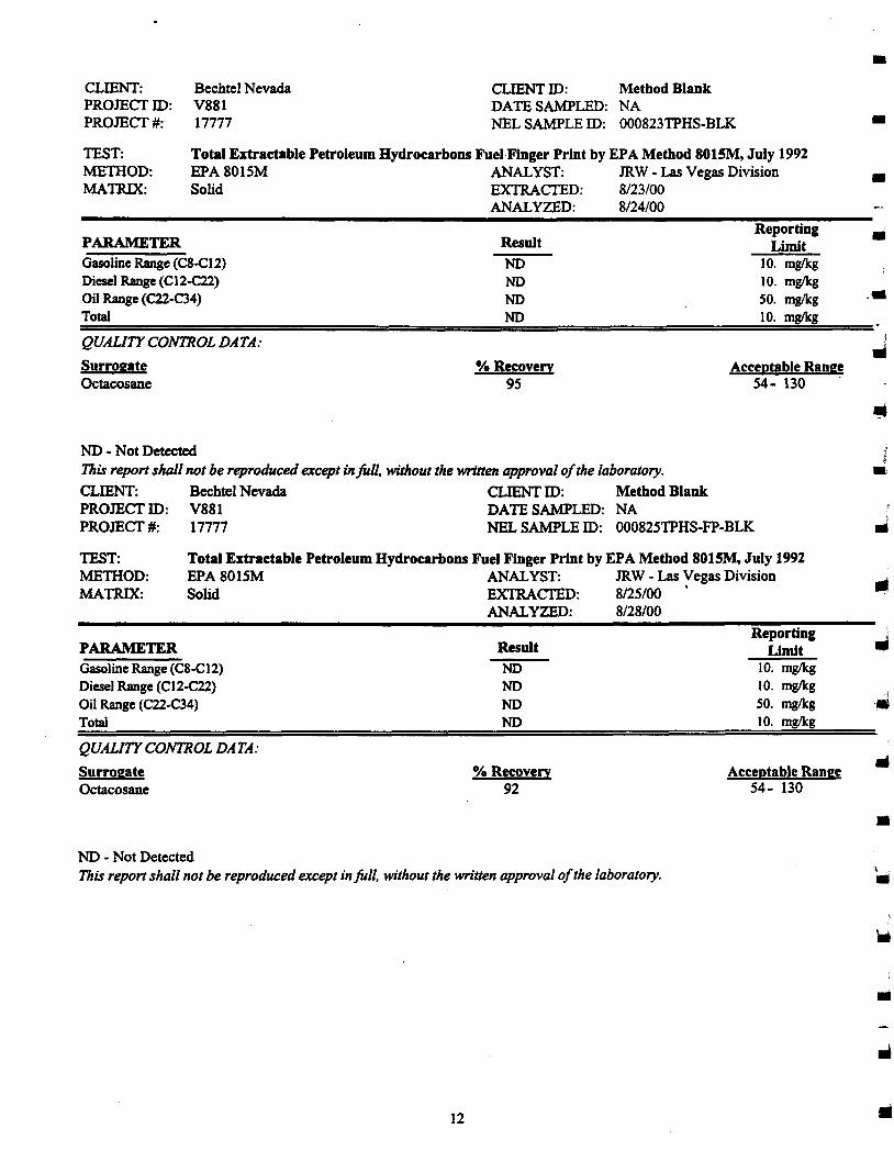
Total Extractable Petroleum Hydrocarbons FuelFinger Print by EPA Method 801SM, July 1992EPA 8015M ANALYST: JRW - Las Vegas DivisionSolid EXTRACTED: 8/23/00
ANALYZED: 8/24/00
CLIENT:PROJECTID:PROJECT#:
TEST:METIlOD:MATRIX:
Bechtel NevadaV88117777
CLIENT ID: Method BlankDATE SAMPLED: NANELSAMPLE ID: 000823TPHS-BLK
•
•
•
PARAMETER ResultReporting •Limit
Gasoline Range(C8-C12) ND 10. mglkgDieselRange(C12-C22) ND 10. mglkgOil Range(C22-C34) ND 50. mglkg ••Total ND 10. mglkg
QUALITY CONTROL DATA: JSurrogate % Recovery Acceptahle Rang~Octacosane 95 54- 130
ND - Not DetectedThis report shall not be reproduced except inJUII. without the written approval ofthe laboratory.
CLIENT: Bechtel Nevada CLIENT ID: Method BlankPROJECT ID: V881 DATE SAMPLED: NAPROJECT #: 17777 NEL SAMPLE ID: 00082STPHS-FP-BLK
TEST:METIlOD:MATRIX:
Total Extractable Petroleum Hydrocarbons Fuel Finger Print by EPA Method 8015M, July 1992EPA 8015M ANALYST: JRW - Las Vegas DivisionSolid EXTRACTED: 8/25/00'
ANALYZED: 8/28/00
PARAMETERGasoline Range(C8-C12)Diesel Range(CI2-C22)Oil Range(C22-C34)Total
QUALITY CONTROL DATA:
SurrogateOctacosane
Result
NDNDNOND
% Recovery92
ReportingLimit
10. mglkg10. mglkg50. mglkg10. mglkg
Acceptable Range54- 130
•ND - Not DetectedThis report shall not be reproduced except in full, without the written approval ofthe laboratory.
12
ii
ill
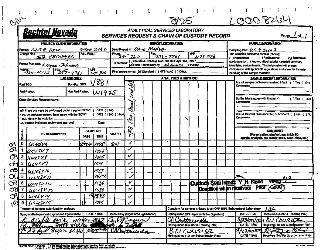
1 ~
L~(J)Q ~~\s1-\
,OJ . t
(:j~5
])"1.~i'
"
B'a le" "a ' lIal'~"~ ANALYTICAL SERVICES LASORATORY •1I11"If;i' "~~a~~ SERVICESREQUEST& CHAIN OF CUSTODY RECORD Page JOf-/-
PROJECTl CLIENT 'NFOAMADON REpoRT INFORMADON SAMPLE 'NFORMADON
Project: c./lITII Zd"" BNOrgI: ;)../~ SelldReportID: tJ,,~ /IIJ..pH'J- S8ll1ll1noSlte: UC--'t 1f...cu" sCharge No.: _ u ~ JI ASI.;Prog.: Phone: .- I' Fax: _ 7 ,. I MIS: J The samples llUbmitted contain(check);
~ C}l(j..O/.,sc: 2-~!> - 7,-)1 -z.'s - 7701 N7s ]'r:?o ( ) H8unIouI ( ) Rldlolcllve ~\Jnknown• '~' .. .» Turnar lid' ( ) Standard· 30 daysNon-rad, 60 DaysRad, Other: contamination. If known. attacha briefnarratlvitsummary
ProjectManager: WA-t~ ~J,I1PJ? 011 • ~Rush PreIImlnaryby. <tIAtzt!YJ Finalby. IdentifyIngcontaminanls. Thisinformation wiD ensure
Phone: • ~ IFax: 'C; 1Mr.:i: compliance wiIhapplicable regulations andallowforthe safe~.;-- Cl5"73 2.:17 - 7 7'I ~.f :b& Flna! reportIonnat:p(standan:t ( ) NT5-WAC ( ) Other: handing ofthe sa_ materials.
LAB USE ONLY , 10 ( ANALYSES & METHOD SAMpLE RECE'PT INFOAMADON
BadSGD: Non-BadSDG: V 0 g' "'§ ~~oontalnersrecelvedlntact ( )Yes ( )No
BadPacket: INon-Rad Packet: W l C[ ss: ~~
CIIenI 5elVicesRepreaenlative: , Dothe labelsagreewith this form? ( ) Yes ( ) No) Comments: _
~WiD theseanalyses be performedundera signedSOW? () YES ( ) NO ~If so.do analyses enteredhereagreewiththeSOW? ( ) YES ( ) NO ( ) NlA !Ie! Wasa Material Clearance Tag submitted? ( ) Yes ( ) NoIf not,icIentIty the variatiOn ~ ." Comments:CSRlnilialsIndicating reviewandapproval: Date: ~ :.:.:.:.:.:.:.:.:.:.:.:.:.:.:.:.:.:.:.:.:.-:
l SAMPLING ~ COMMENTSE ID I DESCRIPTION MATRIX F. (pre.rvatlve, .Izelvo'ume, MSlMSD,Ii DATE nME lpecl" aM'p", rid matrix code, count time, ate.)
),\ 0 uc.I,JSV6 ~bt/. IwR ~il ,/ "'J?- 1 iU~~f"l/ 7 . . I If.II7t ,/
m 2 IlIc..ttSVf I~ c/:.., 3 I tU:'''I sv1 lSI'! t/
6 4 ILU..C/<:V 10 1~/7 0/
)(5 5 , ~ c. 1.Ig1111 I.t;,). -z ./ ~ J t 0 r'
=l 6 UC,/SVJl/ 1S-.3' II' I~ .A'Seall VflNOne,~
~ 7 1.1 Co 'I! 11/3 '": 15J4 V ..... ill" : rwr \. '.Jj:J 8 f!,.£'ICI/IY ~ '"3 v,Gj 9 It Co £ISJII~ l J 1~'15' ,,~ -d
Transfer of samples submitted for analyses Complete for salJ1)les shipped to an OFF-srrE Subcontnct ....boratory JJEl-5ampleO'Relinqulshed (SignatureJOrganization) DATEI TIME Received by (SlgnaturelOrganizatlon) Relnqu!shed (BNRepresentative Signature) DATEI TIME Received (Courier &TrackingInlo.)
,.£... .(1 I"; ~~ ~AJEj.i ol'/~ ~.,~ O~... -.,/ ICI\ ('• .J-In." .nlA X,..i":;,. rT)1J~ n Ali ('IV})') J,r::z.
U ..m,.~~ .'i' Z~I ~~ •• """'l ~...urJ ReRnquished (Courter &Tracking Info.) DAlt/TlttE Received(1sttierSu~&'1lraCtorRlp)
"1A A ';}--j 4-tP' 71t1/F/l. b/-;.,L t!J1W"§" '" , 'JIr~';t,~~,J~ I< AJ r~~( J ,(1 \ f.-a 'rOh':lloolSo.:~ ~ /ReUnqulshed (1st tier Subcontractor Rep) DATEI TIME ReceIVed (2nd"tler Subcontractor Rep)
DlStrIlUI1OfI: VflIIlnl)ll· 10 pe~lne<! ~ !&~a!ory peryOrJ11!I1Q p_~~.!~,!~s '_L .... ~~~~ ..........
I
Qa~-
oe

NEL LABO""~TORIESReno • Las Vegas • Boise
Phoenix • Sacramento
CLIENT: Bechtel NevadaP.O. Box 98521, MIS NTS273Las Vegas, NY 89193-8521
ATIN: Ted Redding
PROJECT NAME: NA 50? I/~"PROJECT NUMBER: 17777
Las Vegas Divisio4208 Arcata Way, Suite A· Las Vegas. NV 8903
(702) 657-1010· Fax: (702) 657-1571-888-368-328
NEL ORDER 10: LOO08328
Attached are the analytical results for samples in support of the above referenced project.
Samples submitted for this project were not sampled by NEL Laboratories. Samples were received by NEL ingood condition, under chain of custody on 8/29/00.
Should you have any questions or comments, please feel free to contact our Client Services department at (702)657-1010.
I'
....CERTIFICATIONS:
Reno Las VegasArizonaCaliforniaUS Anny Corpsof Engineers
AZ0520 AZ05181707 2002Certified Certified
S. CaliforniaAZ06052264
IdahoMontanaNevadaL.A.C.S.D.
Reno Las Vegas S. CaliforniaCenified CertifiedCertified CertifiedNY033 NY052 CA084
10228
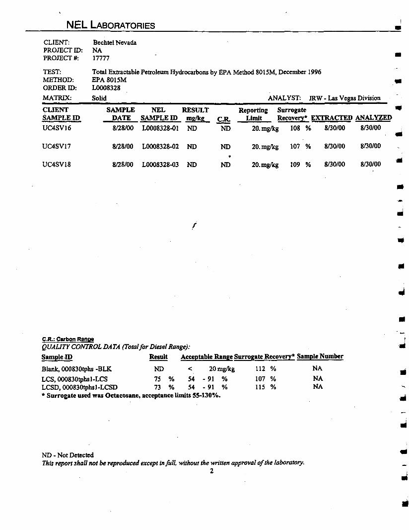
NEL LABORATORIES •
•
•ANALYST: JRW - Las Vegas Division
Bechtel NevadaNA17777
Total Extractable Petroleum Hydrocarbons by EPA Method 8015M, December 1996EPA 8015MLOOO8328
Solid
CLIENT:PROJECTID:PROJECT#:
TEST:MEmOD:ORDERID:
MATRIX:
•CLIENTSAMPLEID
UC4SVI6
SAMPLE NEL RESULTDATE SAMPLEID mglkg
8128/00 L0008328-01 NO
Reporting Surrogate •Limit Recovery· EXTRACTED ANALVZED
20. mglkg 108 % 8130/00 8/30/00
UC4SV17 8128100 L0008328-02 NO NO 20.mglkg 107 % 8130/00 8130/00
'.UC4SVI8 8/28/00 LOOO8328-03 NO NO 20.mg/kg 109 % 8/30/00 8130100
•
l
•
..C.R.: Carbon RangeQUAUTY CONTROL DATA (Totalfor DieselRange):
Sample.ID Result Acceptable Range Surrogate Recovery· Sample Number
Blank, 000830tphs -BLI{ NO < 20 mglkg 112 % NA
LeS, 00083Otphsl-LCS 7S % S4 - 91 % 107 % NALCSD, 00083Otphsl-LCSD 73 % 54 - 91 % lIS % NA• Surrogate used was Octacosane. acceptance limits 55-130%.
..
ND - Not DetectedThis reportshall not be reproducedexcept infull, withoutthe writtenapprovalofthe laboratory.
2
•
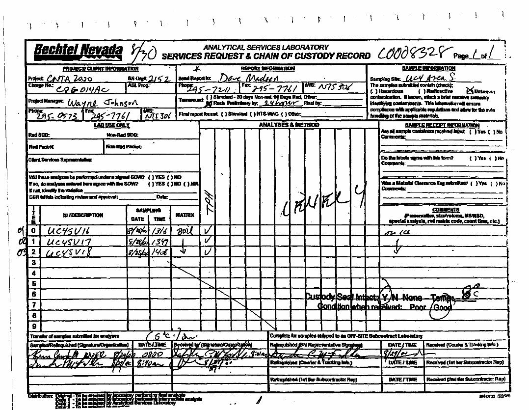
-\ ", l 1 ~ \ -\ t . \ \ I
PROJECmCUENrlWORlMmN
-...... " ... no" ".It ..- BN0Itl':1..1 I( ::L....,111' nv.. '" 0 Ie f)Jo/AC/ (AS[ pq:::
PmlldM8Malir. I. '.- 'f ttJ.., <1"ClIkn.S?I\.
IrlMv,s-: tJt;'73 rlDt.24~<·71t/ ~rlo'
BedImffI!tL"I ~() ANALYTICAL SERVICES LABORATORYSERVICES REQUEST& CHAINOF CUSTODYRECORD
.¥-- REPORT PIFORMAJP!
I~AeportID: ,D4V!.~tl _~r-7:z,IJ ·1~?:17~/ ~N7')fo/
«JSIandlIRf· 30 .....Non_"Oars R", Oller;~:JfRIIIII.,.....,~ 2.1a'h1fW....... FIne1Iv.'-.----
FinlII repad lbnnIt ( ).... ( ) NTS-VIM.C ( ) 0Iaer:
Rad&GO:
Radhcket;
LABUSECM.X
tD-RIdtae:
lfbt.Rad~ .ANALYSES & IIE1JfOD UlREAECEPI1NfOllM1IO!I
ANII..... cantall1..fICIIv8d.... ( ) Vea C ) NoCal••IlIIIIa:, _
( lYe, ( ) N...Do..............fDnn?CoaanIBnII: • _ClIenl8eMcea R........-
9 I I • I ...
-J--t
A7A.....l.Gl
f
"r..._ _'-'..IIv-..:COIIIIENIB=~==.MIIIISD. t......,..., ftJIMlGDlfe.counttlnl•• olc.1 j
.....IedafQeJl8nceT..1IlIIln1RIcI7 ( )Yes t ',NQlConI,..-----------._-- I
""'S: .-A
~:~~c.,.. ,-
..,. I .•
~
Id~I~.~
<,
~~
IUIRIX
r-,<;
....
8M1PL1NG
DATE I ~1D1DE8Ql8l'IIDN
uC,1f5VIiU~yS'1I11LI GYS' Vl~
4
567-8
WltIIeIe ...... llepelfanoJld........SfIM () YES ( ) NO1fM).JJo~"""""'.._"'11e80Wl (IYES ()NO (JIMIInoI, 1denIIift......... 'I s,CSR... lnclbdIngleVlewand..... . ~ ~
~--.rE•
~3
Tmndnrs••,.uubmlleU."" 7 6 'e f 7Jv. .f
~(SfgIl.llnlD"'lIi""")I 1M'
ComfIeIeIar....~ ID. OPF-snESIdlconhctLa--..,
R8pmInId¥e~ I D.\TEJTNE 1Rec:ettel1(CourfeI&~1nlb.)
AgLe{f~ ~......... lComWr;;;;:;:) -lliIE Rece1lell(1at.~Rep)f.F~~~~I~~_f:'/.
po - '0lq' .
~(1""8IMolhclDrR8p) IM'1EI'IIME I ReceINd.-.. 8IabcA"uarRep)
jili....... I~ IQl,9Il
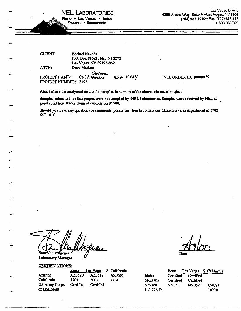
.-
NEL LABORATORIESReno • Las Vegas • Boise
Phoenix • Sacramento
CLIENT: Bechtel NevadaP.O. Box 98521, MIS NTS273Las Vegas, NY 89193-8521
ATrN: Dave Madsen{,t,ful'Y!--
PROmCfNAME: CNTACls3hb $/)6- V?61PROmCf NUMBER: 2152
Las Vegas Divisic4208 Arcata Way, Suite A. Las Vegas, NV 8903
(702) 657-1010· Fax: (702) 657·1571-8B8·368~32a
NEL ORDER In: 10008075
Attached are the analyticalresults for samples in support ofthe above referenced project.
Samples submitted for this project were not sampled byNEL Laboratories. Samples were received by NEL ingood condition,under chain ofcustody on 8n100.
Should you have any questions or comments, please feel free to contact our Client Services department at (702)657-1010.
r
CERTIFICAnONS:Reno Las Vegas
ArizonaCaliforniaUS Anny CorpsofEngineers
AZ0520 AZ05181707 2002Certified Certified
S. CaliforniaAZ06052264
IdahoMontanaNevadaLA.C.S.D.
Reno Las Vegas S. CaliforniaCertified CertifiedCertified CertifiedNY033 NYOS2 CA084
10228
---~_._---
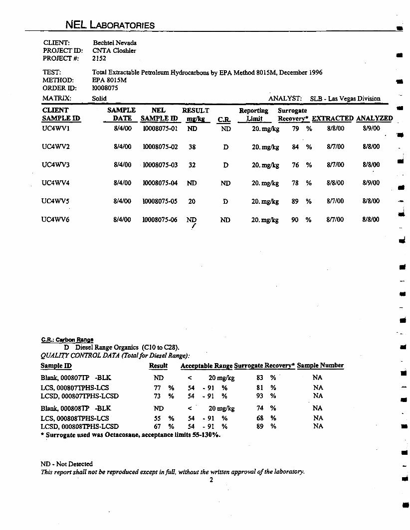
NEL LABORATORIES •
Total Extractable Petroleum Hydrocarbons by EPA Method 8015M, December 1996EPA8015M •10008075
Solid ANALYST: SLB - Las Vegas Division
CLIENT:PROJECI'ID:PROJECI'#:
TEST:METIIOD:ORDERID:
MATRIX:
CLIENTSAMPLEID
UC4WVl
Bechtel NevadaCNTA Closhler2152
SAMPLE NEL RESULTDATE SAMPLE ID mglkg
8/4/00 10008075-01 NOCoR.
NO
•
Reporting Surrogate •Limit Recovery· EXTRACTED ANALYZED
20. mg/kg 79 % 8/8/00 8/9/00
UC4WV2
UC4WV3
UC4WV4
UC4WV5
UC4WV6
8/4/00 10008075-02 3S D 20.mgllcg 84 % sru» S/8/00
S/4/00 loooS075-03 32 D 20.mg/kg 76 % 817/00 8/8/00
814/00 looOS075-04 NO NO 20.mglkg 78 % 8/8/00 S/9/00
8/4/00 10008075-05 20 D 20.mg/kg 89 % Sn/OO 8/8100
S/4/00 10008075-06 NO NO 20.mglkg 90 % sns» S/S/OOr
..-
III
•
C.R.: carbon RangeD Diesel Range Organics (CI0 to C28).
QUALm CONTROL DATA (Total for Diesel Range):
Sample ID Result Acceptable Range Surrogate Recovery· Sample Number
Blank, OOOS07TP -BLK NO < 20mglkg S3 %' NA
LCS, 000807TPHS-LCS 77 % 54 - 91 % SI % NALCSD,000807TPHS-LCSD 73 % 54 - 91 % 93 % NA
Blank, 00080STP -BLK NO < 20mglkg 74 % NA
LCS,000S08TPHS-LCS 55 % 54 - 91 % 6S % NALCSD, 000808TPHS-LCSD 67 % 54 - 91 % S9 % NA• Surrogate used was Octacosane, acceptance limits 55-130%.
•..
ND - Not DetectedThis report shall not be reproduced except in full, without the written approval ofthe laboratory.
2
•
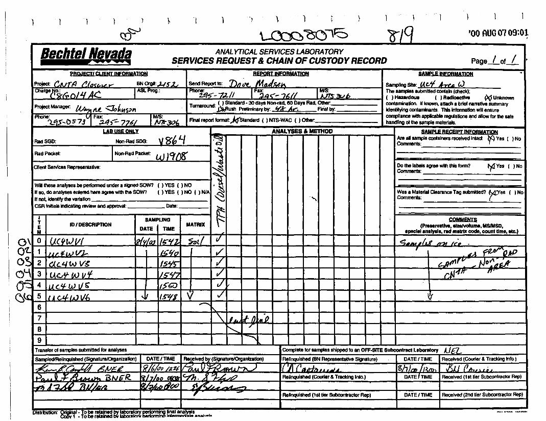
ANALYTICAL SERVICES LASORATORYSERVICES REQUEST& CHAIN OF CUSTODY RECORD
~~..,c:s ~/qco~
Bechtel Nevada~~
) ~ ) ) \ 1 t }
'00 AUG 01 09:01
Page.Lof / •.
PBQJECTI CLIENT INFORMATION
1~30(.,
BNOfgl:.J-/S1.ASLProg.:
REpoRTINFOBMAJh)N
Ut IsendReportto: nod<- ~~JL- fStlCii~-pz./1 1~;.:;6// I~>?b
Turnaround: ( ) Slandard· 30 daysNon-red. 80 DaysRad.Other: _ABush Ptellmlnary by: !(k Ii,.... Finalby:
Finalreportformat:)(Slandard ( ) NTS-WAC ( ) Other:
«",r.'1 1!19ffc,",'VI"".,.)T'r.~LP 01J.f AC.
........."""" "~1lL .;::J.t.".mFax:
...,....J<r'i..t:i$..OS7j :J4~776/
R<IrlSGD:
RadPacket:
LAB USEONLY
Non-Rad SDG: Vf!6 L/INon-Rad Packet: W JCf(J~
ANALYSES" METHOD SAMPLE RECEIPT INFORMADONAreansample containers received Intact hGYes ( ) NoComments: 'I ~._----------
¥Yes ( )NoDothe labelsagree with!hisform?Comments: _
.".Wasa Material Clearance Tagsubmitted? Wes ( ) NoComments: (--------....:.-_---
\I..........
.i/-V777..,7
COMMENTS(P.....rvatlve.slzelvolume, MSIMSD.
speclil analysll. red matrix code. count time, etc.)"-lIt .':=~~
\!I
7 \.1,hY. nl..·o8 ~I/
9 ~
Transfer 01sall1llessubmitted for analyses
Sall1llecllRelinquished (SignatureJOrganizalion) I DATEI TIME I ~lve<! by(8.ignalurelOrganizallon)
·~L~ A,vEL I~7t/d() /~~~!!~A'tLF'0I~~ ..---=--r+.~.u" ..~ BN6R.-RJ7//J; ul~. ]( ~.~ ./?
Complete lor salf¥llesshipped to an OFF-srrE Subcontract Laboratory AJ£lRelinquished (BN Representative Signature) I DATEI TIME I Received (Courier & Tracking Inlo.)
1{'JI(1Jj.ffl.u~..JJ IghJnJh~m,1 xn (lIhHJ;'~ReUnquished (Courier & Tracking Info.) I DATE'TIME I Received (1st tier Subcontractor Rep)
~-J~ 7lJ/J~A. - -1i/~AtI¢1 d~._' -~ --, - Relnqulshed (1st tier SlD:ontractor Rep) DATE/TIME I Received (2ndtier Subcontractor Rep)
DiSfifIUIion: Oriainal. To be retaif1ild IlY laboratorY~ tinalana!rilsCoDY 1 • To be relalnedbillaboralorvilrHform lftjArJlUOtli" ... "n,.....I..

This page intentionally left blank
-
- APPENDIXB
PROJECT PHOTOGRAPHS

THIS PAGE INTENTIONALLY LEFT BLANK
I•
•
•
•
•
..
..
III
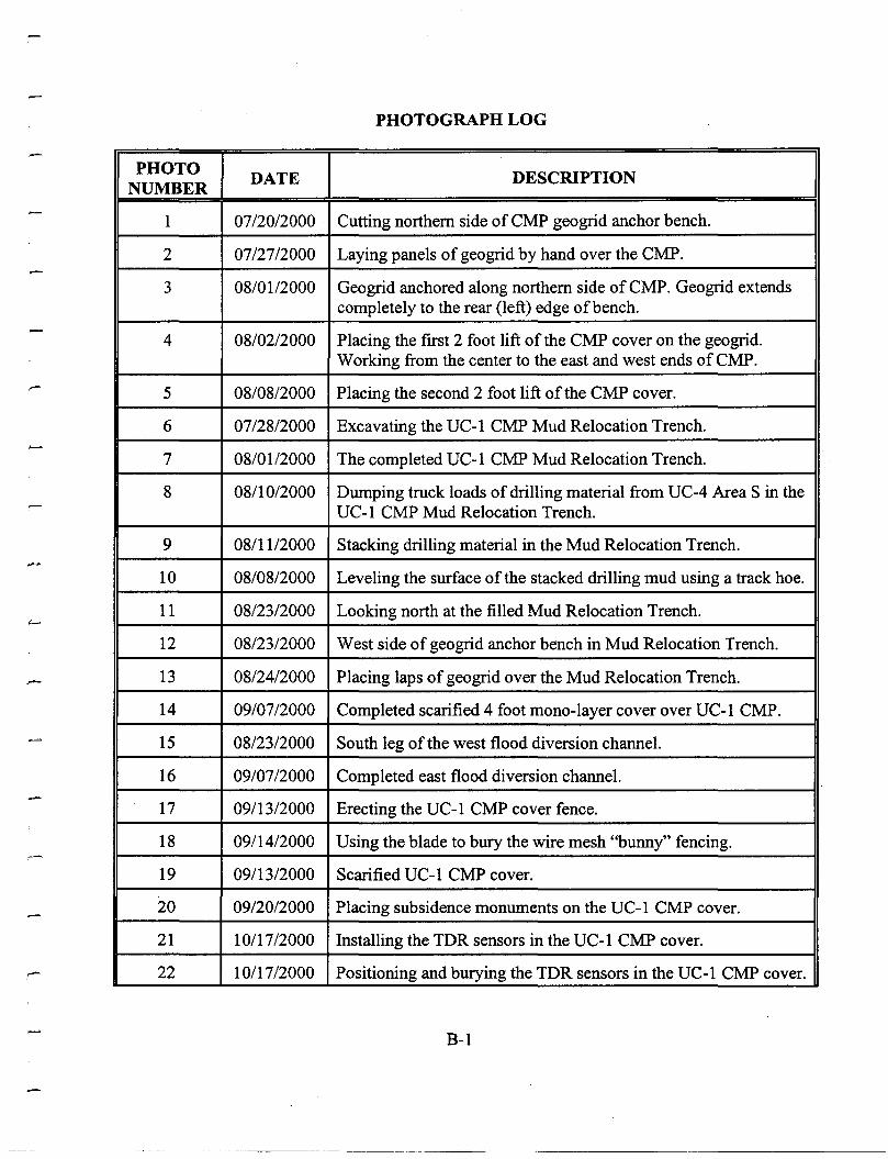
...-
PHOTOGRAPH LOG
PHOTO DATE DESCRIPTIONNUMBER
1 07/2012000 Cutting northern side ofCMP geogrid anchor bench.
2 07/2712000 Laying panels of geogrid by hand over the CMP.
3 08/01/2000 Geogrid anchored along northern side ofCMP. Geogrid extendscompletely to the rear (left) edge ofbench.
4 08/02/2000 Placing the first 2 foot lift of the CMP cover on the geogrid.Working from the center to the east and west ends of CMP.
5 08/0812000 Placing the second 2 foot lift of the CMP cover.
6 07/2812000 Excavating the UC-1 CMP Mud Relocation Trench.
7 08/01/2000 The completed UC-1 CMP Mud Relocation Trench.
8 08/10/2000 Dumping truck loads of drilling material from UC-4 Area S in theUC-1 CMP Mud Relocation Trench.
9 08/11/2000 Stacking drilling material in the Mud Relocation Trench.
10 08/08/2000 Leveling the surface of the stacked drilling mud using a track hoe.
11 08/2312000 Looking north at the filled Mud Relocation Trench.
12 08/23/2000 West side of geogrid anchor bench in Mud Relocation Trench.
13 08/2412000 Placing laps of geogrid over the Mud Relocation Trench.
14 09/07/2000 Completed scarified 4 foot mono-layer cover over UC-1 CMP.
15 08/23/2000 South leg of the west flood diversion channel.
16 09/07/2000 Completed east flood diversion channel.
17 09/13/2000 Erecting the UC-1 CMP cover fence.
18 09/14/2000 Using the blade to bury the wire mesh "bunny" fencing.
19 09/13/2000 Scarified UC-1 CMP cover.
20 09/20/2000 Placing subsidence monuments on the UC-1 CMP cover.
21 10/17/2000 Installing the TDR sensors in the UC-1 CMP cover.
22 10/17/2000 Positioning and burying the TDR sensors in the UC-1 CMP cover.
B-1
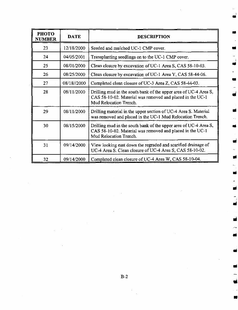
I PHOTO I DATE I DESCRIPTION INUMBER
23 12/18/2000 Seeded and mulched UC-l CMP cover.
24 04/05/2001 Transplanting seedlings on to the UC-l CMP cover.
25 08/01/2000 Clean closure by excavation ofUC-l Area S, CAS 58-10-03.
26 08/25/2000 Clean closure by excavation ofUC-l Area Y, CAS 58-44-06.
27 08/18//2000 Completed clean closure ofUC-3 Area Z, CAS 58-44-03.
28 08/11/2000 Drilling mud in the south bank of the upper area ofUC-4 Area S,CAS 58-10-02. Material was removed and placed in the UC-1Mud Relocation Trench.
29 08/11/2000 Drilling material in the upper section ofUC-4 Area S. Materialwas removed and placed in the UC-1 Mud Relocation Trench.
30 08/15/2000 Drilling mud in the south bank of the upper area ofUC-4 Area S,CAS 58-10-02. Material was removed and placed in the UC-IMud Relocation Trench.
31 09/14/2000 View looking east down the regraded and scarified drainage ofUC-4 Area S. Clean closure ofUC-4 Area S, CAS 58-10-02.
32 09/14/2000 Completed clean closure ofUC-4 Area W, CAS 58-10-04.
B-2
I•
•
•!..
•
III
..
..
•
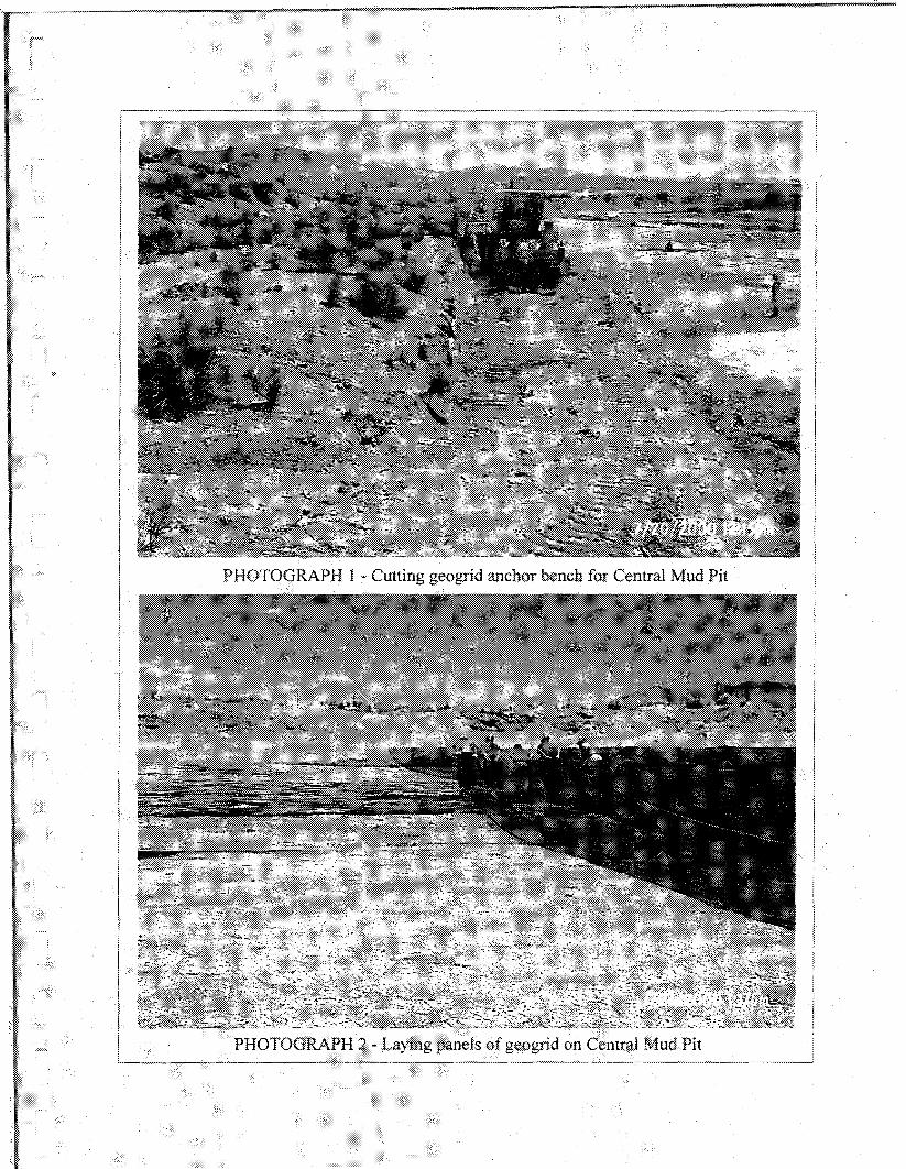
PHOTOGRAPH 1 ~ Cuttinggeogrid anchor bench for Central Mud Pit
:'~~OTOGR~;;~ * Fir~! 3footlift being place on CMP geogrid
-Placing the second 2 foot Hfton the eMP
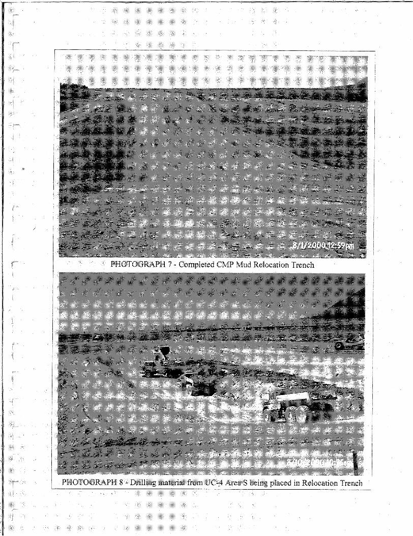
PHOTOGRA.PH 8 - Drilling material from UC-,4 Area S being piaced in Relocation Trench
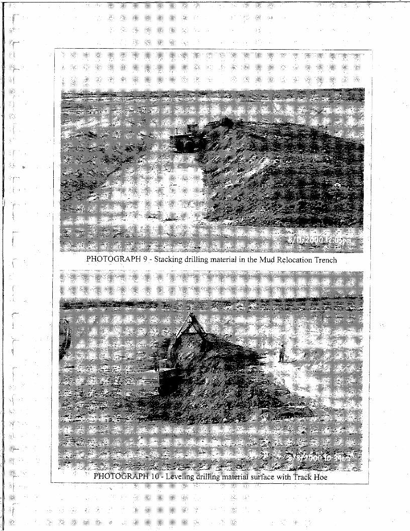
PHOTOGRAPH 9 - Stacking drilling material in the Mud Relocation Trench
PHOTOGRAPH 10 - Leveling drillingmaterial surface with Track Hoe~~--~--
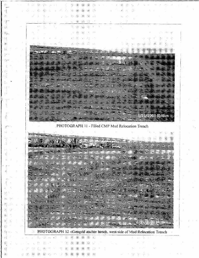
PHOTOGRAPH 11 ~ Filled eMP Mud RelocationTrench
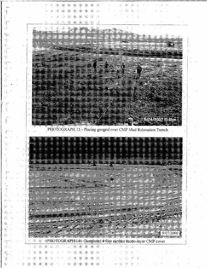
PHOTOGRA.PH 13 ~ Placing geogrid over CMP Mud Relocation Trench
PHOTOGRAPH 14· Completed 4 {O0'1 earthen mono·layer eMP cover'--------
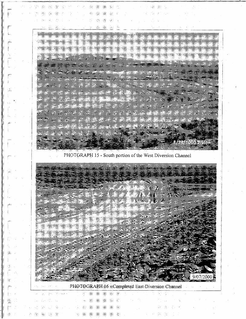
PHOTGRA,PH 15 * Southportion of the West DiversionChannel
PHOTOGRA.PH 16 ~ Completed East Diversion Channel'--------_ .._--_..._~ . _._•...................................__...~----
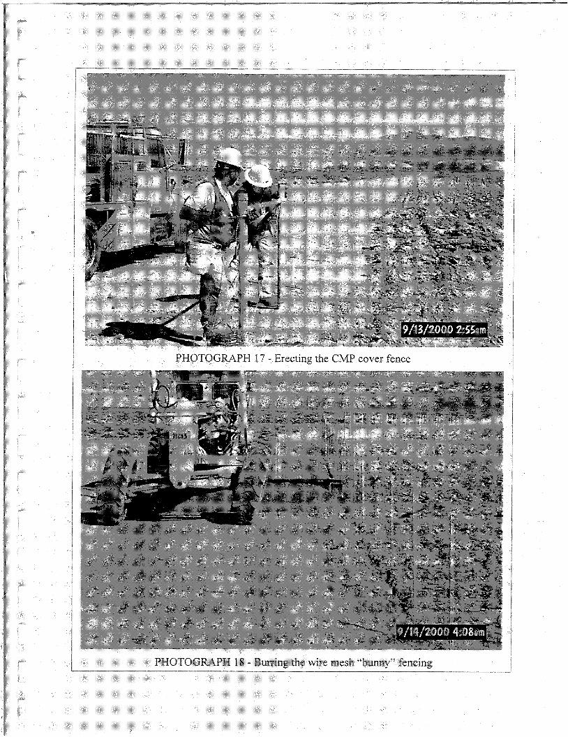
---------~-_mm<m~~~----------~-----------...::.-
PHOTOGRAPH 17 - Erecting the CfvlP cover fence
PHOTOGRAPH 18 - Burring ih~ wire mesh "bunny" fencing
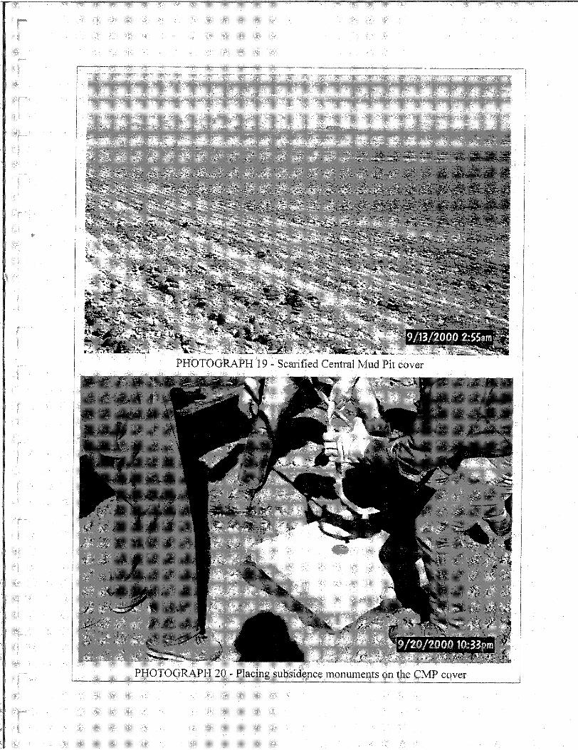
:::.~:
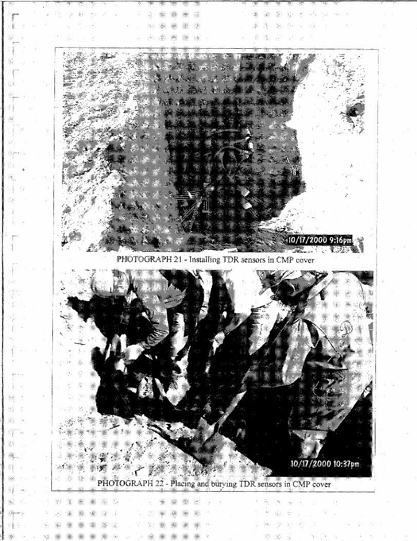
-&
,~.
-~
r ,
j,
.'-:--
PHOTOGRAPH 21 * Installing TDR sensors in eMP cover
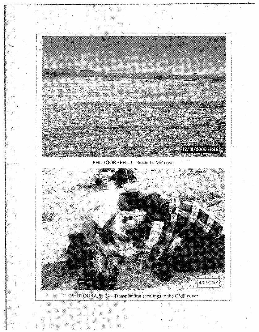
PHOTOGRA,PH 23 - Seeded eMP cover
."',"",',' ".
PHOTOGRAPH 24 * TransplantiI?g seedlings to the CflllP cover-------
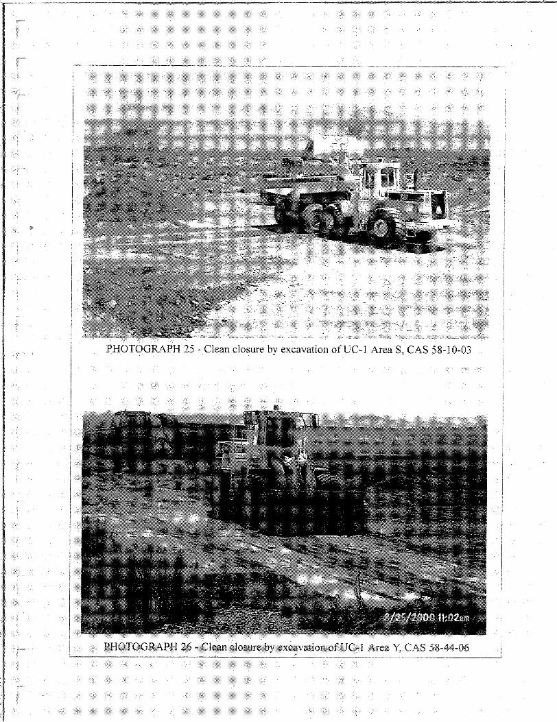
PHOTOGRAPH 25 - Clean closure by excavation ofUC-l Area S, CAS 58-10-03
II PHOTOGRAPH 26 - Clean closure bv excavation of UC- I Area Y. CAS 58-44-06'-'---_ _•...•....•.•.._ _ __._ __. ". ...•._--_ _ :~ ~------
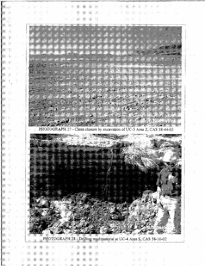
PHOTOGRA.PH 27 - Clean closure by excavation ofUC ~3 Area Z, CAS 58-44-03
PHOTOGRAPH 28 - Drilling mud/material at UC-4 A.rea S, CAS 58- i 0-02
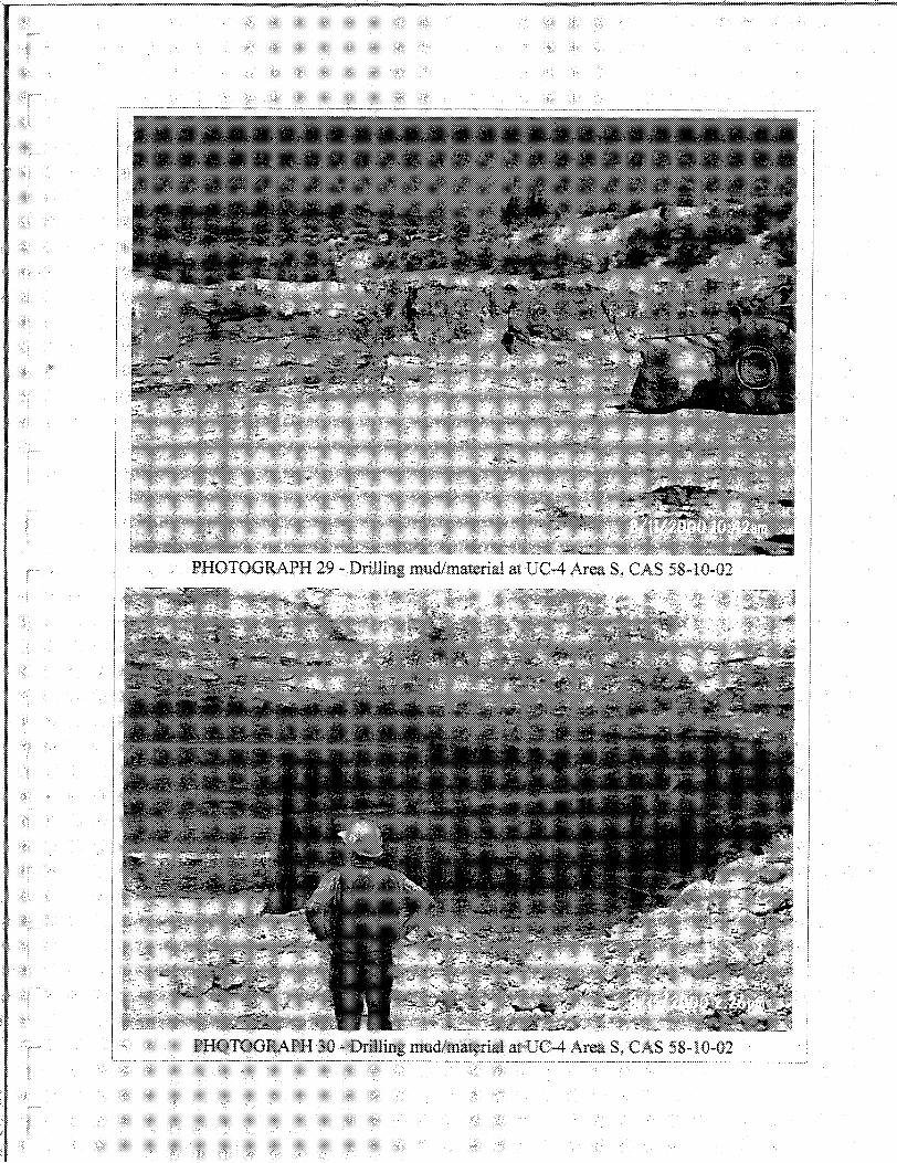
PHOTOGRAPH 29 * Drilling mud/material atUC·4 Area S; CAS 58·10·02
PffO'fOGRAPH:W * Drillilug mudlmat~rial at UC4 Area S; CAS 58·10·02
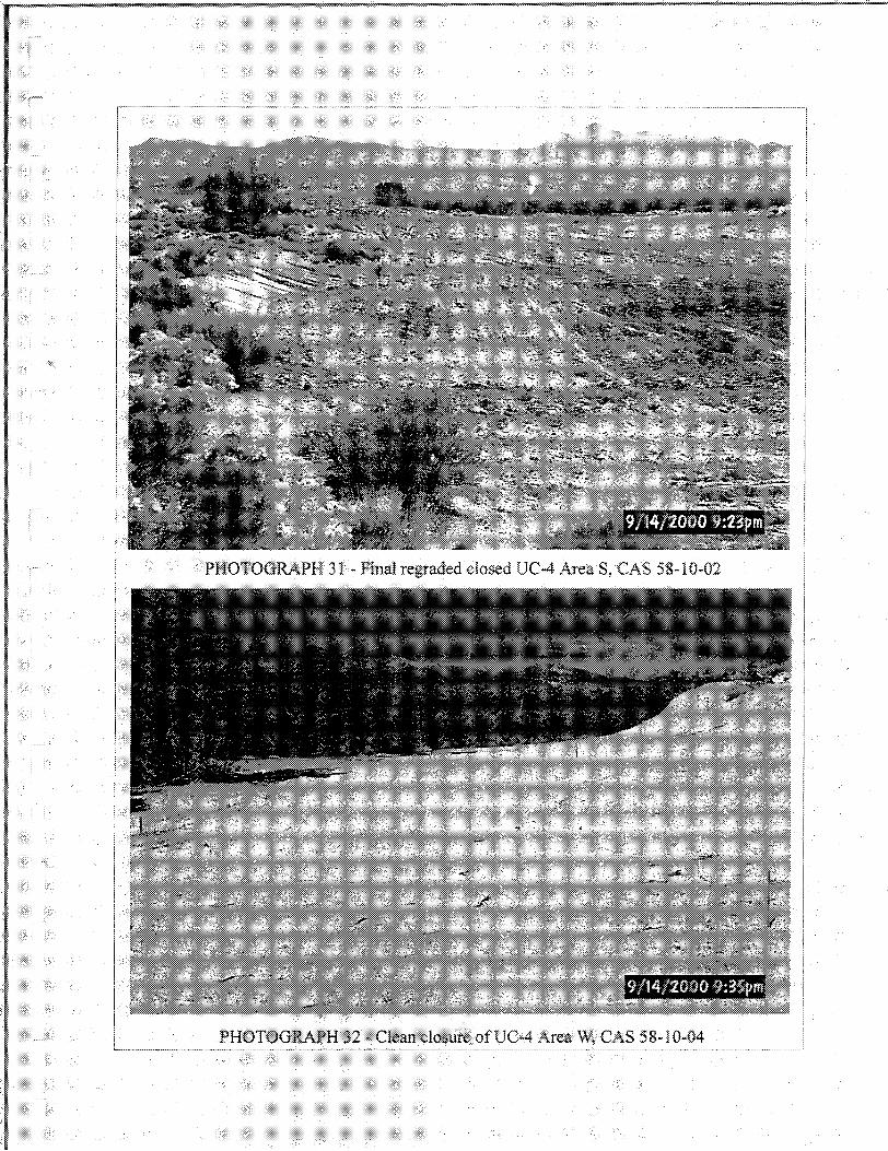
r~~"~"~'~--~~ '''~'~'~~'~''y'y'''''''''~~'''''' ' '.'.'.•.• ' '.•. ' ' ' '.' ~ -......•.............•......•........• - - -.. -.- ,
PHOTOGRAPH 31 ~ Final regraded closed UC~4 Area S, CAS 58-10-02

...,
r
r:i
t!
rI,
,-i
ri
APPENDIXC
AS-BUILT ENGINEERING DRAWINGS AND DESIGNCHANGE NOTICES
THIS PAGE INTENTIONALLY LEFT BLANK
J
J
Jj•
J
J
J
J
.J
.J
J.J
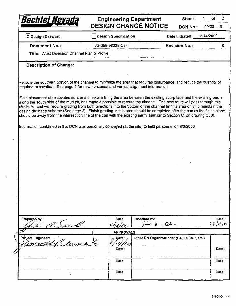
Bechtel Nevada Engineering Department Sheet 1 of 2-- --
....-.... ............... ". .DESIGN CHANGE NOTICE DeN No.: 00/08-419
~
LJDesign Specification 8/14/2000l!JDesign Drawing Date Initiated:
Document No.: JS-058-98228-C34 Revision No.: 0
Title: West Diversion Channel Plan & Profile
Description of Change:
Reroute the southern portion of the channel to minimize the area that requires disturbance, and reduce the quantity ofrequired excavation. See page 2 for new horizontal and vertical alignment information.
Field placement of excavated soils in a stockpile filling the area between the existing scarp face and the existing bermalong the south side of the mud pit, has made it possible to reroute the channel. The new route will pass through thisstockpile, and will require grading from both directions into the bottom of the channel (in this area only) to maintain thedesign drainage scheme (See page 2). Finish grading in this area should be completed after the cap as the finish slopeshould be away from the intersection line of the cap with the existing berm (similar to Section C. on drawing C33).
Information contained in this DCN was personally conveyed (at the site) to field personnel on 8/2/2000.
pre~bY: ~. I Date: 'CheCke.d by: I s/~~i:~,/d.~L·'~· /?: ~"?-~~ ~4/C'o V..:-J u .~-
(~ ( APPROVALS
p~ject Engi~~~~ ,~ j~;~)Other BN Organizations: (PA, ESS&H, etc.)
-..l/;'/YUL'1 ~ ~ ......, ~
V/ .I
Date: Date:
IDate: Date:
Date: Date:
BN-0404.doc
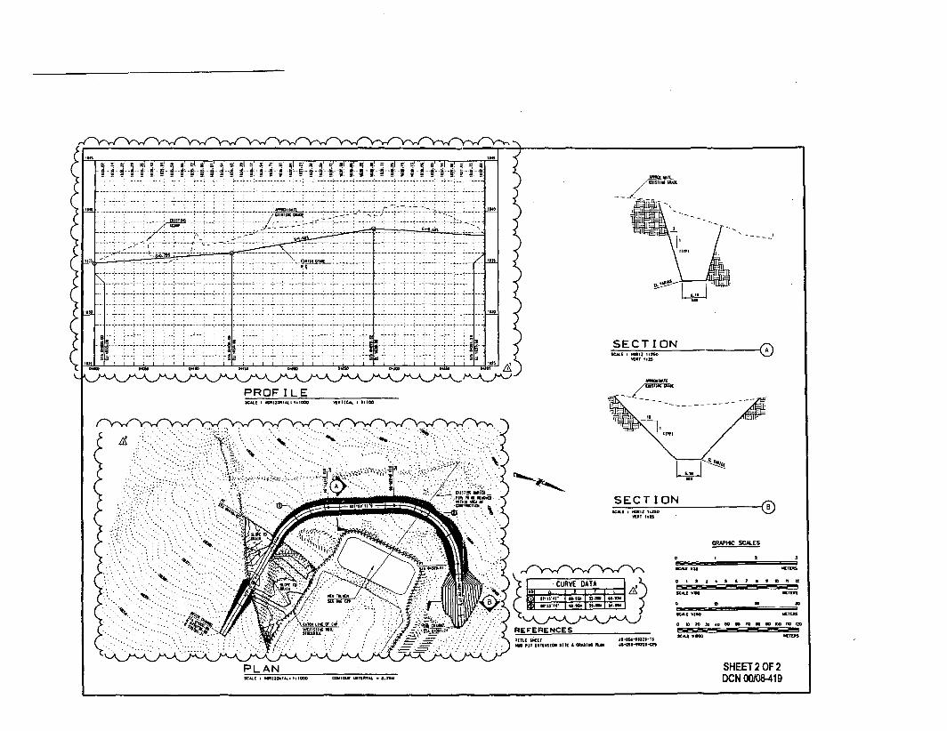
~,;.
BIIII,IIIl~II
~II
Ia
8a
8 II
•••
lD
zo
IIII1IrIIIIII
~l,'!!II'
I
Ii:IJf
zo-~~
I-;;=
oii
w~
V>~
-,III.//1I
~~"
~.
I
Ig~,m
mIrI
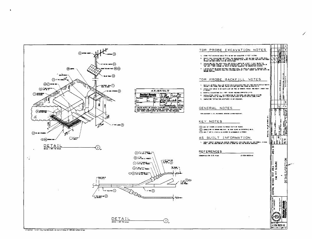
/
zot; .a«~"·""..,VI"-VI-.oJ
c(......,C
JS-os'-t1221-w1
1. SHICI ,llE UCAUTEo SOILS 10 A II[lilil 1101 [lCE[lIIII 15 fEET 14,$UU.
2'. Wlll.lfT TH.t.T UCAUTlOlf1 111((1 OSU It:. RUUIRU,IU. TlK .... I-.l1l SlOE SllWt SUlLIE LSII U.rss SNOIlIIlC IS lJTllIlU TO~1l(vUI SIll( nOPE fllUIlE fOIl .OUI nl .. IOlE'IUtH .1.110 1CI11IT0IIN5 STATION UCA'UTlC*S.
J. Huvnllllil FO' TO' .....n SHAlL lOT EltHO '0('111 Of 4 fElT (1.22111 NLOI TilE£llnlllG GROUIID SUllf'tE. UUEII( tAUllOll S"All 1£ EUICIUG Illlille UCAu1lOll OfTME LAST 1 fGOT (JOSMIII OJ' SOIU TO 'IlUEIIT O"MAelN' 'liE UIiGUllllI' "!)CillO.
4. ,01TCIl 'ITCII 011 OTHEIl SlIlUllE EDIIll'1I£.llT S"'ll IE UUO TO UUUf[ TIl[IICIlU fOIl.IIlIIlCIIUlfS. TIlEltClI[SSlAlll(AIIIII... UIlIl0lIfOOTI10$IIUIHOIIIl(UISTlI'MOUltSUIl'ACE.
I, tACKrlll IUoTEIlUl SII'll 8l JIlUIVE SOILS UUUf[D fROIi Til( 11111: DOtl,11 ,UfLECTllMETUsUrtSDlt ITIlIi ~IOI[ '10 1OI1T(NtIIlC SUlIOM LOC.t.TIOWS SIlOllll 0IIl~nll' .1.
2. VERifY TIIAI nus fa IE UClflLLlO AU UU 01 HUll. nTU. AID lIotlS LiI'U lUI'1ICIilS.
a. ....eetru [It.nAtIOllS III' FOOl (]05.ln 1lA1I1IJ1I COli'ACTED LIfTS.
4. IJilShuAlIOI. UUFlll. 'tiD tOIl'''TIOli or TOI I'Rot[ AaIO MOIllfOll1tG SUll"UcunllllS IILL IE DOC IY rlElO IlCllllltlillS TO II"CII IIUlwt tONGITIOIIS,
5. tOWACllONT£SlIIICFOI'CtlfflllC[ ISIOTl£llUlll(D,
FOIl [QUI'III:IT llSl.II[f[IIUCfOI"IIIG.lS ... 51-unl-11.
1, SUBIIITSUII'EY JllrOllIlAIIOIISIlO'lllGtOOtDI .... I[lDCATJOIlSFOIl TilE fOil ,!tOIu. 111111'IUtlS, '110 lll[ 1IOII1H1Il11I' SUTIOM AS 5110lIl 01 fNE E.. III((ItIIl' oIlAlI"'S.
CD liSE 4$' ELIOn is IUD[D TO IUollt[ lIorll Of 11l(1C1l,
CD COIlJ$[Cl It.. TO IUlOUIlO IDO SIlUL I[ 1If,0[ 115111' ill UOIII[lIlIC 'UO.
CD UlI4· In's 111(11 51 AS 1£[0(0 lOACCOlM:lII'1[ ....lItU,
TDR PROBE EXCAVATION NOTES
AS BUILT INFORMATION
KEY NOTES
TDR PROBE BACKFILL NOTES
COrMMICATHif SIlE PlAN
REFERENCES
GENERAL NOTES
AS-BUILT
~ UNLESS NOTED IIY MAAICfO , AlL. DI S. NOTU.~ RfFfPlEHCU AND CONSTRUCTlOH FEATIJRB ARE CORRECTID,! AM) WEllECOHSTftUC'T(O AS SHOWN ON THI50MVI1NG.
4"MEl_@
SCALE: NOT TO SCAlE
DETAIL
•• SlMUo@
- / •· ..... "'0!MCOJII.IIlIfii\
IU Jt:EDEol \::/
loCAlE I IClT TO SCAli
DETAIL
JS-<lSI-!I221-12
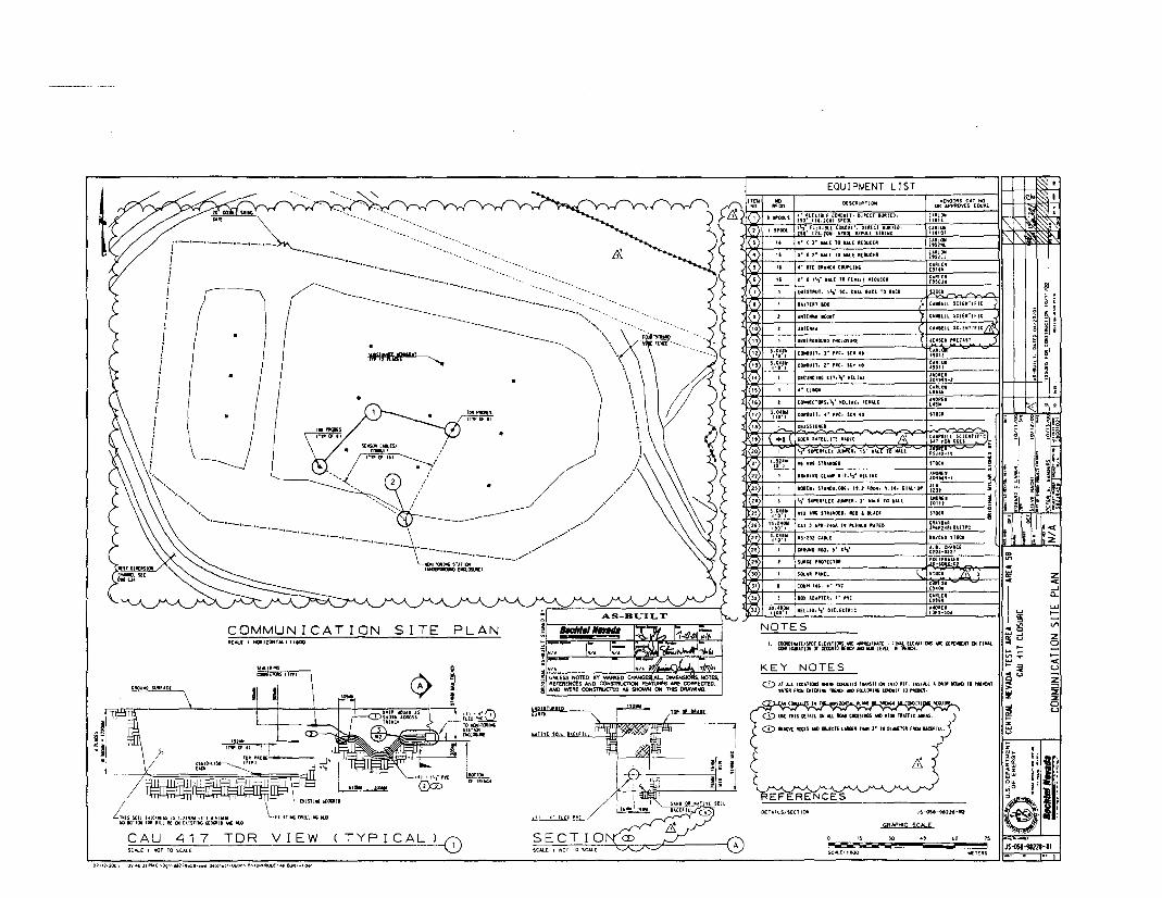
z...--'Q..
UJ.....VI,
~I........U
Z
~:::I!:oU
~[!;;,~ ~81- ~~
~I !;;; ~- !~ .i i§!I
Iii
~II:1~;
~~
<8'
~:
21
'Ii lIio 0,
JI~""211-1l
STOCI
CUtO"£'1511
"ilLnal)
AIIDRnltlll
VENDORS CAr HCJ[Jl; APPIltDVt:D EOUAl
1I10lEI204'''-1UllOIlUnA"
C,utOIl.'01'
tUlOIl'll\!
URlOll"lIar
CJ,IlLOIlE'52LJ
C,lRlOIlE'!IIIlL
JS---05I--'JI21I-'I"l
MET(RS
50 15
GRAPHIC seN.(
o ".........".
GI(JlJIlOIIlCIIT."'Il(Llu
UNOUGlflMlO (IitlOIL/IlE
U1(Itll ..
S·. t"IUoL( TO lMU Il(OUCU
COIIDUIT, S' I've. Stll 40
EQUIPMENT L1ST
.·nE'IU.IlCllt~IIl'
IUHR' 101
CONOUll. ,. P'C. St~ 40
UttISlIlUT. I'"~ SO. DUti. UU TO UCI
DESeR.prleN
'" I 1'''1' VALE TO nllUE 'EO\lCU
'liTEII... IIOlHH
4" • ]. l&Al[ TO1lAL£ ItEDUC[l
" 'UIlBU CONDUIT. DIItf:CT lUllED.l$O' 115.20111 SPOOl
11~' rcmur CONDL/IT. 01lUC1 IURIU.no' 115.20111 UOOl IIPUll STRIIIG
).IUfti1111"
).0.'.1,o'1
L ClOIOllunlSPOT u(nTI(W$ .. """'OIlll.lTl • FlIlAL(lE~"I(IIS llIll O(l'{lUNt ell flNlLCOlf'I""ml'llfliEllliIlIOIII:IlCII.IMlIIDLEW[LIIlTIII[Ill)I,
CD AT ALllOUTlOlllS"'1II[ ClJIlUlTi TIlMSI1ICIIllII0"lT. IJrlST/ill A 0111' IOIG TO1'II(¥lllt'AJ(RfJlCll(IlUIl.lIllfllEJlCll_FU.lOl'I"UJrIIJITTO~S.
onAllS/SECTION
NOTES
KEY NOTES
"
(ll"Un SClUITH1CUT 110ft GOU h--tilltliti :::::;c:::FSJ4J·1~ i"AWCsrIlAltOEG ,TOCI
022)1 , II000OUlGCLAllPllT. I'lI"I+ELlU ANOIU
~104 • .,-\
2'.>1 , IltOO(ll. $T.lIIo,uotlE. It.t .Ip•• W.J4. OUL-U' '" Sun''ll' $Ul'tIlFlU JUIlP(Il. J' 1II.ll( tc .AU ANOUI !10111
~.O4l1l110') _" l" nUlIDU. In .. IUU SJO(l i
26)I 115~'~· CAT ~ "'Il-14GA ,. 'LUIUIl "un
21)1 'j,O:,'r 1l'-ll1CAlU
;IlOOIlO 1100. " .".
Slllle( '1l0T[CtOlt
SOI,UI'.lIlU
,;')[ • [COUI'llll" 4-"" I ~;:~~Il.. ...~ .A>.uo ." ''1e I~AltlOIlE!!51
lJ}I ~IU1OD'''j IKElIU.," G1ELHTIllC H~f;~~o.
l~'" ,,'") SPOOlS--1 nllOl.-"-"-"-"
~I""..
!IH/A
SCALE I HOT TO seAL(
SECTIO
(AIITII
/lAllY( SOIl heHll
iJ...L...i: ....illL!lL
\IW.I.lll!IU
,HIi
!
CTYPICALlQ
Sl....IO""lOttIIfCT1llSII"..
"'\''''-11. ........lONTALI 1 liDO
~_._.-.-._~.-.-.
r-'-'-'- <--,__._._._._._._._._._._._._._._.,.., .., .. ,
' ,! -----,..,------- -.! ~- \! \!" i........ '- '\I ",' \I ,
' \1" , __• iI om...,' ",I ,' JI , .
! /i • /' /1 '- /I /'" /''>. /'
-, /'/,._._._._._._._._.-._.-.-._. .-.-.-._.-.-._.~~T:~~I
StAl.t I JrtClT TO SeAL(
CAU 417 TOR VIEW
L
t
g~1~I
O~ 46·~\!'We \O~n\9a~ JIk>!>a\.<M-"~I(I\"."Qe>I"''' 8\ lDiOJ'IlO8E\ ..... !\uI~\ .. 1.O<j"
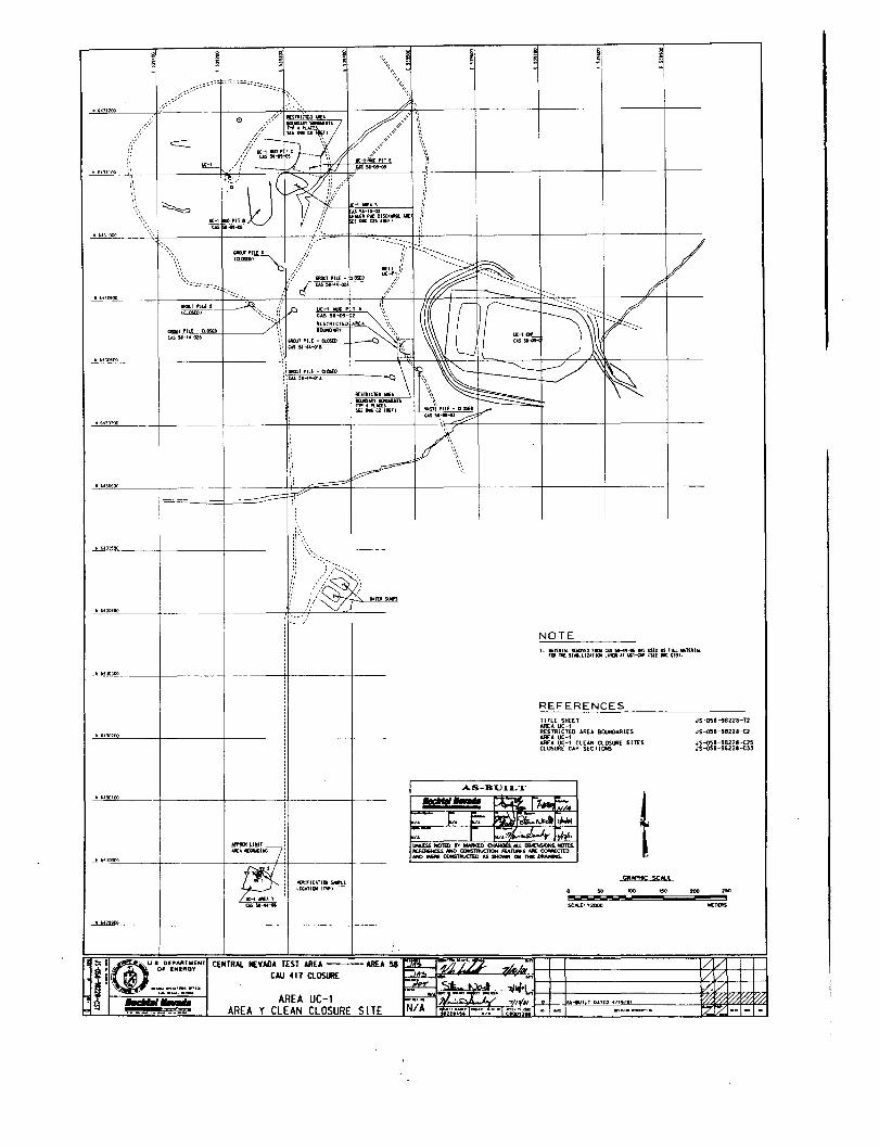
GlWl PILE - 00l25l0
Il£SlfllCTUlAlllEA1lUCllo'tr IOUilWTS'Yf' 41'\JaSSU DCCZllEFl
~I
'\\~~~ ~IoUl~ PIlE - tltlS£1l J"'"
US~~~
NOTE1. IIlTtlIALI[IIOYEDFOW,.............SUS(DI.$F1U.TUU....
rill TIlE SUaJLllUllJl L"Dl aT lJtl-(W IS[[. WI.
REFERENCES
! :;. rGJU... ce..AflITMENT- i j 0# ENEflIQY.*i ,__,.'g ...,.,......
Af'I'tIDlLJIlI1"
K1tIFICATllJI~(
LatAlllliIl,",,1
1It-1 • .l1ws...........
CENTRAl. It:VADA TEST ARUCAU 411 ClllSlllE
AREA UC-lAREA Y CLEAN CLOSURE SITE
AS-BUILT
TITLE SHEETAREA. UC-1RESTRICTED AREA BOlN)ARIESARU UC-1AREAUC~1 CLEAH CLOSURE SJTESCLOSURE CAP SECTIONS
CR.tfHIC scAlE. ..,....$CAL.[: '1:2000
JS-OSI-9822a-T2
J5--o58-18221--C2
J5-051-98228-<:25JS-oSB-982ZI-C33
1/1/1 I I1/\/1 \ I~/I/I I 1
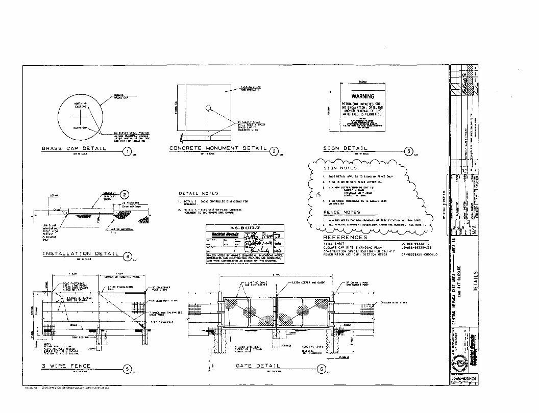
0 •,,!!.. ~§,:
!.\.
I ji!lXi h~F il~"i~
CHIClEN.UtE IrtPI
WARNING
l-lXlGAUf'05TUID CORNU POSt
~[ PETROlEUM IMPACTED SOIL.NO EXCAVATION. DRILLING
AND/OR RElIllVAL OF THEllATERIAlS IS PERMITTED.
"....
SIGN NaTES
TITLE SHEET JS-05S-99228-T2CLOsuRE UP SITE &. GRADI NG PLAN JS-058-98228-C32CONSTRUCTION SPECIFICATION FOR CAU <411REMEDIATION UCI-C/rE'. SECTION 02B" SP-98228A58-<:OO09.0
1. fENCING IIl[[TS THE REOUIAUlElIlrs OF U'ECIFICATlQIri UCTlDN 1)2"1.
e...., FE""", c........ '" 0""""0'" "'_ .... """,...... SEE ecte 1. ~
SIGN DETAIL
FENCE NOTES
t , nus OiTAIL "'I"I.IU TQ SIGNS ON F[NC! ONlY
2. SIGH IS lIIHlT[ W,TH aucl. LETTERING.
3. WINIIiUtf L£TTEll/lONl HEIGHT 151DANGER - " ..11W0000"'TIOH • J....CONTACT _ " ....
oi, Sl~ STOCK THICKNESS 1$ " 1I0\0£/0.06J5OFt GflEATEJI
L4TCH II:EEI"ER 4NO GOlD{
DRilL HOI,. .... EPOXY8RASS CAP TOCONCRETE DISC
8h1 SUA'IE Y $lolA
lOR Pf\£CASTICAT-IH-i'LAC
AS-BUILT
UHLESS ~TW IV MNlKfD ,ALl Clthl . NO,""MFEMHCES NIIJ CONmll.JC1lClH FEATURES AIlE CCJMECT&D,N¥:) wERE CONSTIlUC'TlO AS SHOWN ON TffiS~
MONUMENT DETAIL 0'"
DETAIL NOTES
I. OlTAIL 2 - sttO~ CONTRQ.LEO DlME/rCSIOHS fOFtlIlC:JU,l[NT.
2. QiUIL" - FOllY CAS.T-lhl-PLACE CONCItUE~"T TO THE: OIw[NSJON5 SHOWN.
CONCRETE
1.52"
ACTUAL I,lEASllR£ \/ALU£SAfTER IhI$TAlLATIClll. SEE0.. CJ2 fOR LDl;ll'IOtil
eN SURVEY SHAlL PftOVI
ASS U
CORNER Olt TERlltllUl PAHEl
INSTALLATION DETAIL 0,,,
BRASS CAP DETAIL
3 WIRE FENCE
~4--_U
JS~-lI2Zl-Cli
0. 1
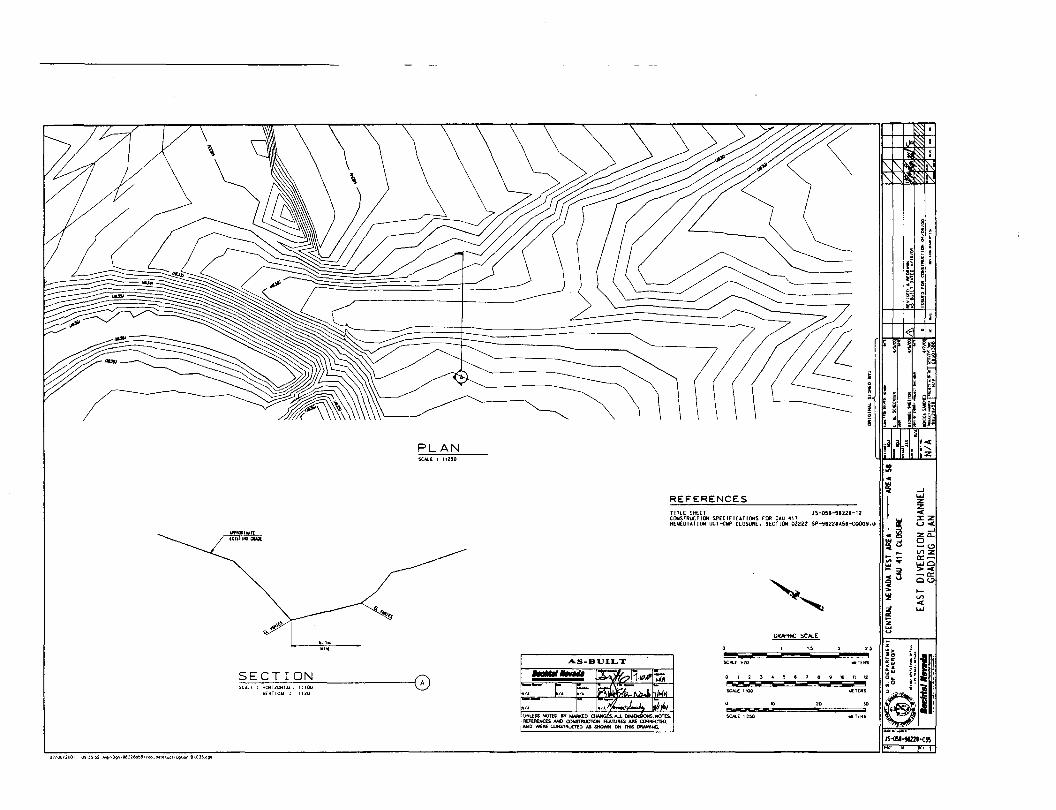
I
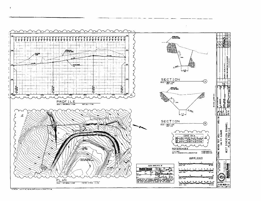
Z<l:--lo,
-~~~~~3~
iii
isIiIi
III
zo
31UO~d
VN
'Ild
-----'---"
;0;-
13NN
'IHJ
NO
IS!l3/110
1S3M",:~~:.~
_j'3llllS
01JLl~IlY
JA
O.....
O~\!
~:''!\...
asY
3lIY--
Y3ijY
IS31
Y(JY
A:Jl
lYIU
N3
J!"'''.'d.a.n~:
IIIi
]
_a.- j"
W--l
lJ...orru,
OD
lltlO1U
._,t11lG
1UJ1S
lMO
llI
yU
.•O~IS
''''1lI5tllO
LO
",IIO0
11
'(1J.lIn
t1-'n
'1
--+-4
'-1"''P
';I--+--+'W
'''-!11Il.
.t
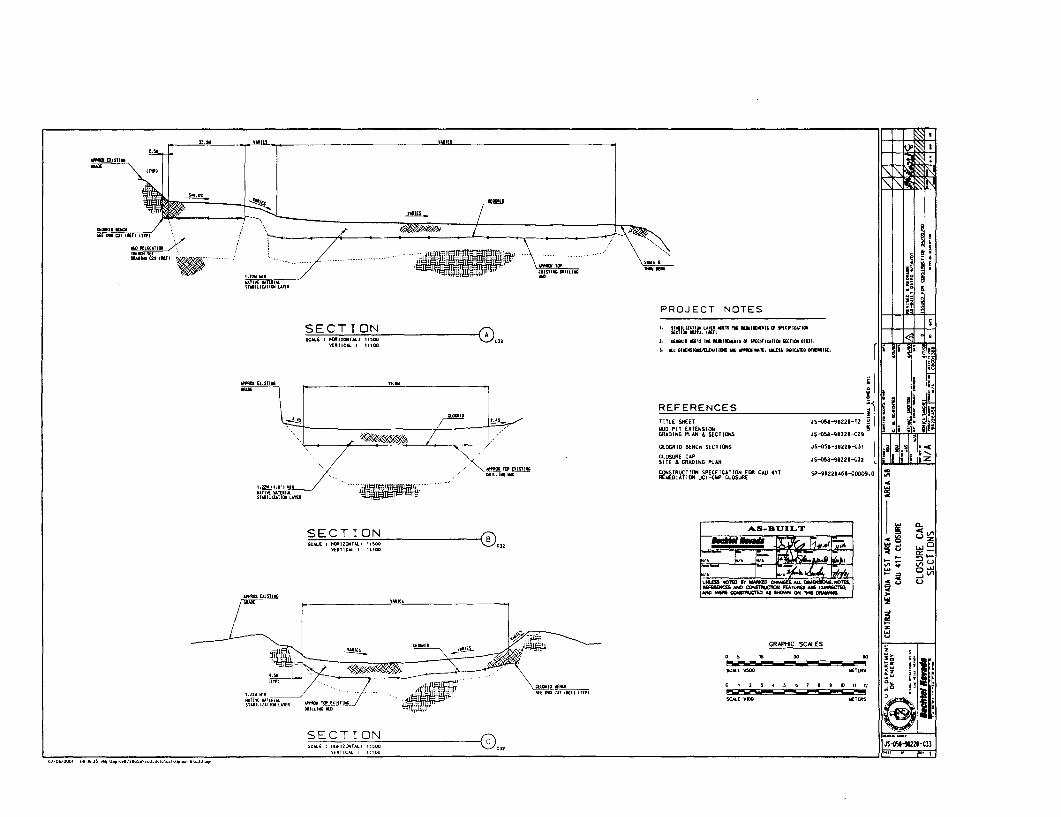
~N
~
:a
:a
SNO
ID3S
dYJ3~nS01J
]lIlSO
lJLl~
OlJ
a<.;Y
3llY---
nil\'lS
31Y(JYA~
1YlI1N
3J~_,
YIN
!-.l..OJ.
IIIs
.(/J
!i<
VI
~il
W~d
U~
=~Z
~:llIt.
~'(
W;;;..
'ile;G
z
~~([
~z
~~
.~
W~It.
u::;~§
LL~~
!j..w
ig~~
~i
([
~~
lJO
MY
JllO
f
!Bl.ICI)IIJS,
..'J
VI
WfazfUW""")
a([
11.
IQ,I'''1/1o
01
1'0
III'JOy
..
YlIC
IW'I
Q)S
ll\lal
M~I;
"~i."~M::
i§~2'~
~.
~.
" ;e~§
u
Iu
u
•«
ca
!
ilJ ,
!
ZH
ZZ
0:"
00
.....~
I-~
l-I-
U§
UU
W.:
ww
vd
VI
V1
JJ
jl~~~
-~ ee
~~.~
-~w;:;-
i~~
~=
~'1;i
:I~=~
!z~=
".~;~~
::i~............
~..,
~
il::i
Il' _~;5
~"O
M~
Hi
BliiII:

SITE & GRADINGSCAlE I 1i00Il()lllTAlI '1400
PLAN
REFERENCESTITL.E SHEETIIIJO PIT EXTENSIONGRADING PUN" SECTIONSCLOSURE CAP SECTI~
WEST DIVERSION CHANNELPL.AN &. PROFIL.[EAST OIYERSIOH CHANNELGRADING PL.ANDETAilS
JS-05'-912ZI-T2
J5-051-91221 -<29JS-OSI-9IZ2.-c:U
JS-OSI-9122I-c3.
50!
WEI£II:S
JS~-iI22I'Cl2•• 1
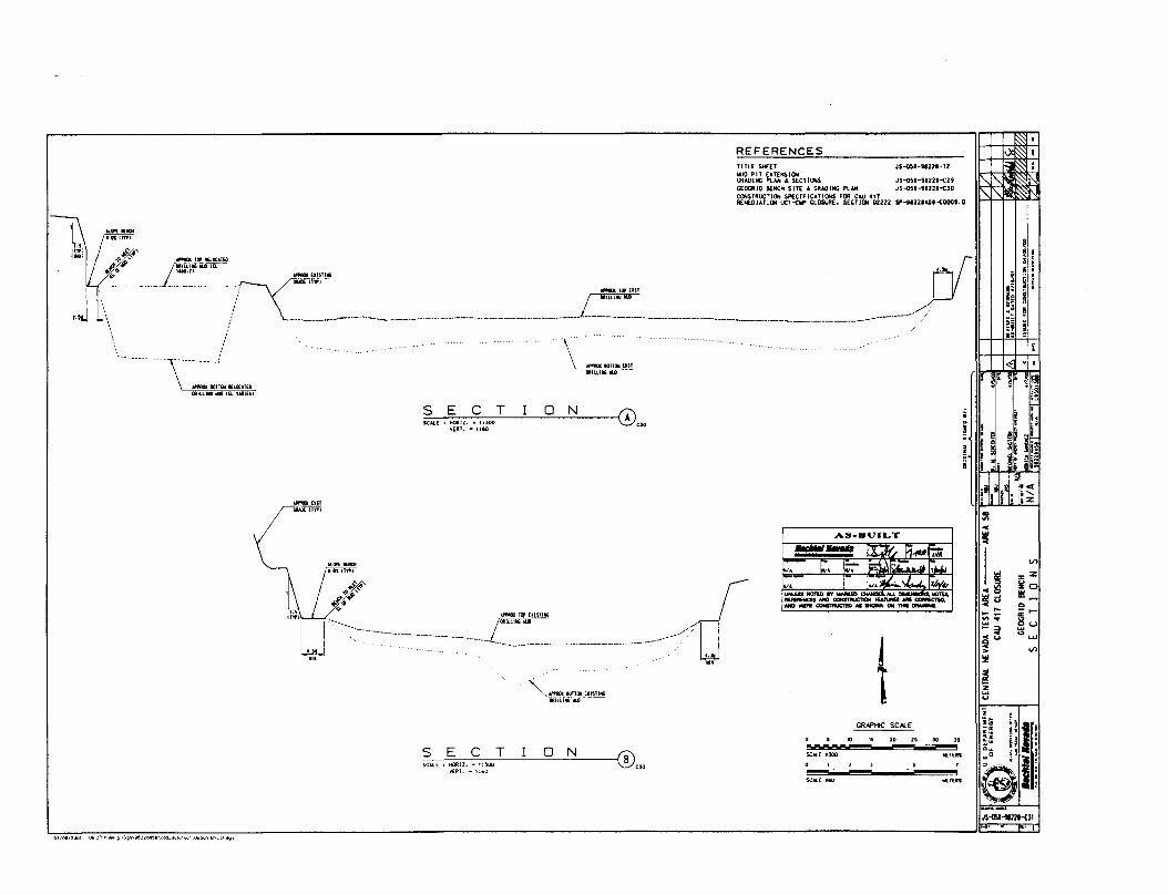
REFERENCESTITlE SHUT JS-051-9I2Z1-12Ii&JO PIT EXTENSIONGRADING PLAN & SECTIONS JS-OSI-91221-t29GEDGRIO BENCH SITE & GRADING PlAH JS-051-91221-GJQCONSTRUCTlC»l SP£CIF!CATlC»lS FOR tAU 411RU4EDIAT1(Jril UC:1--CW CLOSURE. SECTION D2ZZZ $P-t'ZZIA~'--COOO'.Q
~. ;,.". ~"OOT ION 0".VERT•• '160
'"
'":z:Z~oi;lj
'"-0-
8<..>..."' .....
~I'3
~ ~
I~ ~!H..'I 8,;;; .;;~ir~'
~
i
h~d~::
"''''~~~u>!i!
~z...u
.~
rf'"./<
1
AS-BUILT......... :I: ~ Fl·,.,F.;. C. ~ rn 5:': .. l~
." r '"J ~~
~~~~:.i.~~NG WE_ CONITfIJCTB) AI IHOWN ON 1'HII ClMlMNa.
~~IlOTTOll(.IS'I'"llRllLIIGIUl
'l'f'IIllllUST~
IIfW1I,'lI"lllllX-'DIlIUtlllillLOlELllJS.lI
_._..•. __ . ~_EIIST".-----7 -"",: _",mT..! .__-- __ __l:_~~_~__. .._.._._.._. .._.. . _
-_... \,"""."",",,,,, ~UST... 11"""' ....
s 7",,,. ~"ooT ION (~\'."'EAT • • ':iO
GRN'HIC SCAlE
JO'15202~30J~
SCAlE "JOel IIlET[fiI'S
SCIIIL( 1110 woors
JS~-1Im'CII
01106/2001 Oll·.n·ll,.." II\DII"'lIenl:lo"lI\c""~a~I<l\",,I\()PI>Q(I8\C}I.a<Tl
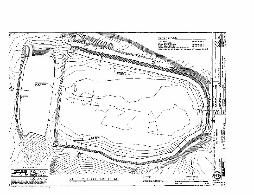
•• 1
Z-<-'Cl.
0 0zZ115-
ClQ-<-0:~o~o(l
..........II>
J5~-1I21l-elO ,...rnss
15 20 25 JoO
SC.....E 1:300
REFERENCESTIRE SHEET J5-()58-982211-T2KlO PIT EXTENSICIlGRADING PLAN &. SECTlCNS JS-OS8-ta228-e29GEOCRID BENCH S£CTIONS JS~5.-t8228-C31
CONSTRUCTION SPEClflCATlOHS FOR tAU 0117R€IrIIEDIATION UC1-(1IP ClOSURt. SECTICW OZ222 SP-982ZIA5I-eOOO9.0
ElCA~lTI(Jj lI([JS nt: il[WlllElIIOfS.rs SPUlfICJ.TICIl ~CTll»l02222. tAUl~ ... __ <. ......... ,ZONTAL: 1:300
SITE & GRADING PLAN
-
.IIPf"llQl EDCE IlEllbTElllII:lllllllf lID SU OleC2111l[f1
.50.'10(~
\JttoIlfSS MOrEa 8Y Ir.WOO:D ctWfGES..-.u. OIMEHS1OHS. NOTES.flt.~ AND COHSTRuC1"lClM fEA1\JI\ES AA£ CORRECTED,AND WERE CONsmucTED No Sl10WN ON THIS DRAWING.
01l06nOOI IKI'J7.l6 ..... "Dtn\IHI22aa=iI"oa.GOIO'''''\Opuonll\C)OO9'I
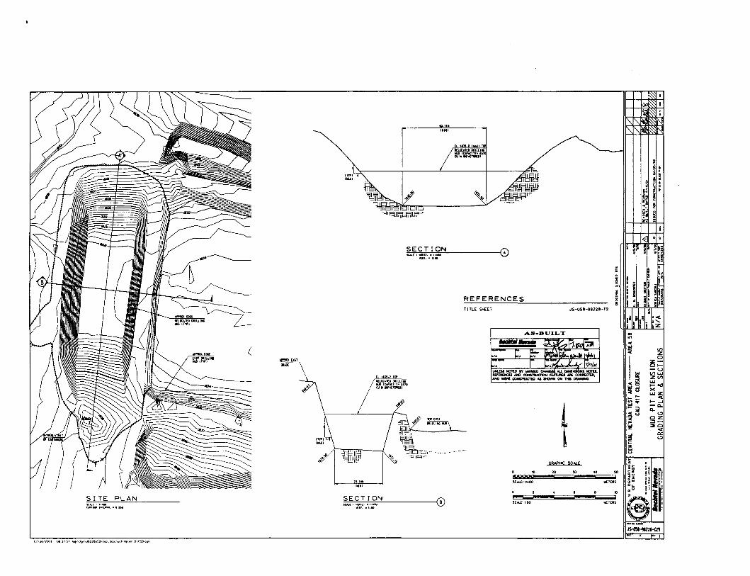
~~
5i~
-,I
-,;:
~
0~
~-
-s~I~
J~~
I1~fpo
~A
.!~..l
I~
Sk n~;!
;II~
r-
~!¥I~II
~~ h
SN
Oll:l3S
'iN
Vld
~NlaVH~
~;.;,;;
~:-
NO
ISN
3!X3
lidann
.,,';'':',,:,:,-;,:,.~
llll'>O
lJU~flY
J(f)H
~.A
.OtllN
):10
7~
~,
B~
Y"llIY--
nlR'
1S
l1Y(]yA~
lYlH
NlJ
"'~'.'d,a
'on
I'
V/N
Dlit
~~11Ol
lo.r.~/,
01
1'
J.lA
e-U
.'fWI~"Il:rsIAJM
VI
WUZwa::!:-
..W
~~i(1;'
u,Ws~~
a::~~!ilja
:::~
Z*:!
0l-
iu
'i.W
"'~VI
iT
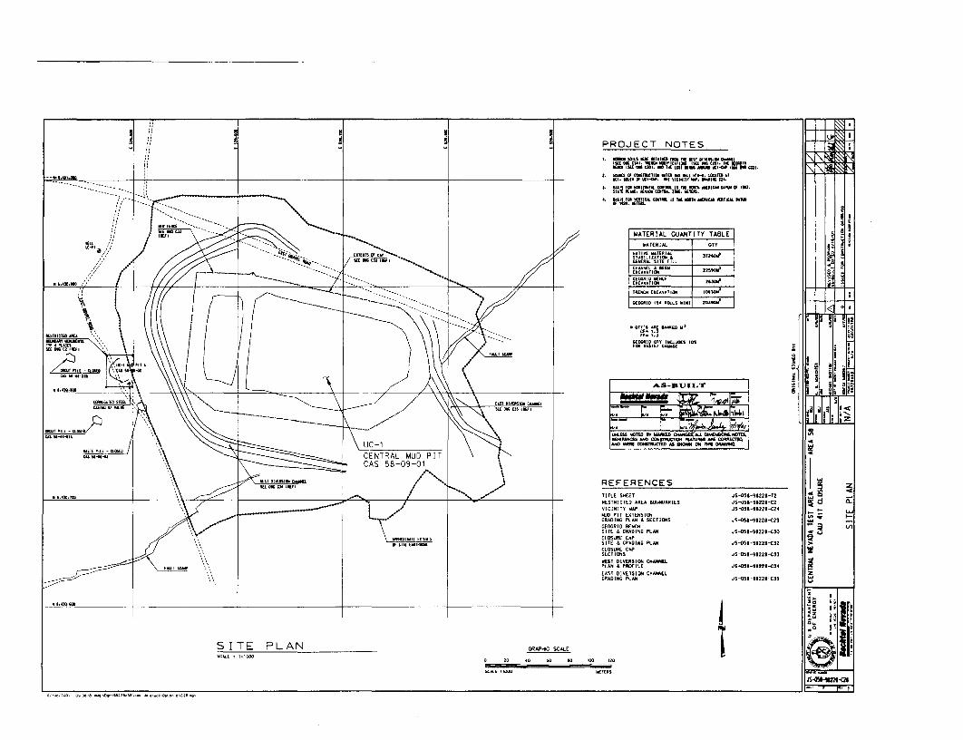
(/l
-l [TJ
lJ r p z
I~ Ii
".
:+ t--
---_
__...--..
1
[9
1••
~ g ~f-
=+-+
-+-+
-+-l_
:0 IT1 ." IT1 :0 IT1 Z o IT1 VI
~e--
~&
~fi
~
iU~
~~
~~
~:::
~~
~~
~~
~6;!;:
:;:
!:;.
!G)
,U.1.DE
PA
RT
ME
NT
i:;.
""\
OF
(HE
AQ
Y
•lIil
ii,)
••_~.
"_..
..51
,.......
..'..''
''.
SIT
EPL
ANN
/A
tJl:
IGIN
AL
~JGJoI[ll
In
IlIC
llll
SlG
TlD
ll
-"':
CT
-.-"
....
..<'
''''''
11I
",,,.
,n<
ao.1
2..
.~11
1/"
ClG
OIl
8ll
IilE
VIY
D..
MD
lII••
"'-
«U
lTA
T_
II"
1
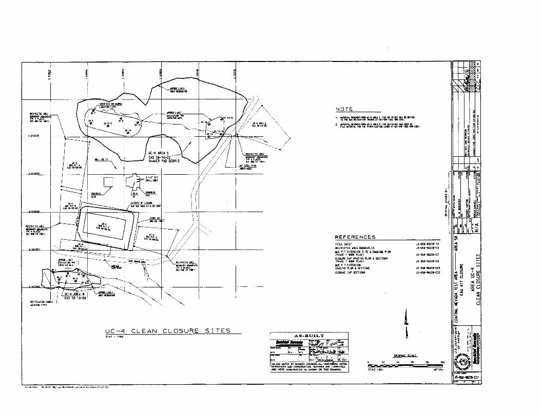
UC-4 CLEAN CLOSURE SITES
IJ ~... ......,"" -.....-r·--...... "-- 1""-~,,~~~, WA 1l[1OAAD11lG " • -........ "<,CAS 58-IO-o~ "'-.. <, ~
'l'UlflClTl(llSMl"\.[ •UciTlill-(NrI
"'
A-....
- , ,
",-,~-~~~--~~~, ~~~~---,~~~\~~~-, ~-£rir-_~_~~~~~-_----~-- -----:'>~~~."I;'~ IUD"""."
"<. \ ...-,
~I!!I,8~~
"_II OJ iii
I~llw. ~~3 e;: ~;, ~
II!~ ~
If ~li
c
~
IwU1..,>-U1....c~ I..,
wa::~d ::J::J
U1- <0... - .., --':::: ... a::w... ::> <-e Z~u <..,> --'W w
~~u
:JIl
•
eo KlO
.J5~'-"lZ'-Tl
JS-D5'-9I221-{;4
J5~'-1J'22.-e'
JS---Q5I-UZl'''''''
JS-OS''-'122.-e29JS-ost-9I221-elJ
t.. eo
GRAPH(; SCALf
SC-.L..[' 1'800
o ec
NOTEt , MUlllM. llllOllf:l FlllII UCoo4 MlU I ltAS N-1D-tZ1 WJ .~lICAlU
TO 1101tIIIlllllOtATUIl fll[IlQl AI\ll:I-(W I$([ DIGuti.
2. IIlT[IIIIM. IlllllMD llICIiue....., I LCd "·'0--041 US uKD ASFlU 1Il'01l.. Ia. Til( ShlllllAlIlIl LAO" UC:1~ lID: OIl Uli.
REFERENCESTlTlE SHEETRE~TRICTED AREA 80JNDAAIESlrlJO PIT EXTEHSICW SITE l GIWIIMG PlAN(PHASE 1 IORIl. PloUt)CLDSlfl[ CAP GAAOIJrtC Pl.'" .. $ECTlIJISI PHAS( 1 Oil. PlAN I
YJO PIT UTEHSllJtCRADING PlAN .. S(CTll)6
CLOSlJl:E CAP YCTIm.S
AS-BUILT
t. I:. 1~~oI1l.....-.... 1U/7 h-I1.oJI;,;:
r I:~..,..J..J.. Ii,v.,UHltS$ NOrED ., IrIL'RaD~olMeNSiiNS. NOTU.REfEI!.ENCES J<l'It) COHSTftI..ICTlON FEA1VfttS N\E COMECTiO.AND WERE COHSTftl.ICTEO AS SHOWN ON nus t:lf\AWHG.
7 //l"l/'~,"">/ ""
£llEllTS(6 ClMUllf.jtilsu.oaCl&tllllE'
ut-< IUPIl'c.u"-01~
tUJOC,7J . Irt----
w~-ot-oJ
r-r-
kJl~....
lIlST~lcrUl"'U
iiiiIuIlllOUOTSTTf4p!,...t,(,·USUOIGC4tfl(f1
tU35.95.1l
''''''''
JS-tl\I-II22H21i
12001 UII ~~ 40 ....·\O~n\lIt1nll<l~tl'~Q<l.<IOI"',~l\OpUO<'l6\e27 "'J

~~------
r-,.: \\
G G"'SIlMllflAD \~~:i"" !i
..,"',1" ..."'ri" .""., ~. /)-:$tlAI.UllltU, "Wy-,o-o, "
,In :' ~2 (:(:
..-U---- --- ----t.",,"w ... \\,
"-7\L - ;;::~:,',\"............. _ .l ~ , ..,, ~____ _ • ._
~:-~'~, CA/llSTU
/~tMR£liCJ'.I tlJlCl.l....!
ec-rII.IlI'IT£
CASSI-ot-<lli
i //---.. ,/..,.-./'ec.:II{T( .1oD -----.-
......,-~ "ttIOlETl'olD
~1£-3 stlIT1lE1II WTLIEII
tAS5I-2!l-G'!
• HE I'lL( -a.lJSUIjfS'''''-(I1
a.... USTlPlU-Q.05OlW$l....+l
REFERENCES
a..... lAST( PIlE - ClllS,uCASSt ..... -a
tIRE. SNEETfESl1l:IUED ARE" BlJ..I()ARIESClOSlR: CAP 5£CT!OO
J5-051-9822I-T2JS-OSI-9'228~3
.15-051-91221-03
10
"'''M
CAS 5B~H)3
UC-3 AREA Z
UN.fSS t«mD IV MNaD ALL MCn'ES.JEfDENCU MD <XJNmIlUCIION PEA'JUIIIEI ". CON'EcnD.N«J 'MfIIl 00NSI'llllCl!0 AI SHOWN ON 1HI$ DfIIAWNL
SCIU..[ I 1I1'!KI
UC-3 CLEAN CLOSURE SITES
ISUO FDIl CQN5TJU:tlClM 04Xl!1OO
"£VISEC iUClltl~....... u.t JolED""15 1
....I.ln ..,
1I,,_... •__n __"
N/AAREA UC-3
CLEAN CLOSURE SITES
CENTRAl. J£YAIlA TEST AREA --- AREA 58 ~~=f!i.!-..!!!!J_---~~j=t::::::::======jtz~ttjjCAlI 411 CLllSlJl[ ,.to G)U.a. DEPARTMENT- i . OF ENERGY
• JI: I c __••__,.
5il , .
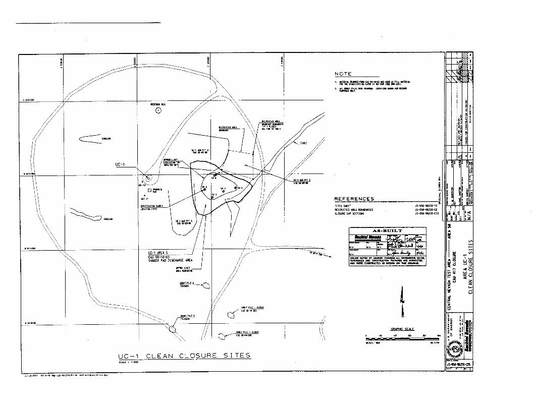
~ !NOTE
1. =,TPri.E-s~~~= ~ypH;;':f-= YIlt ::"~I~lUl'"t • .tIU. GIlIlI 'llU ....... lllClll_..- 'QlKa.
Nf'OSES 011.,. •
"I!~.::~
~el
~~&
~! ~I~ ~
i~ il.,I: ~
;_ AI
;~ ~r: ~
1<81 °1.
JS-tSI-1I2lI-m
:IlcI§!c
III
11........III
'I .....ua::
~~ :=l:=lVI
.0... - ..... -J"' ... a::u~i • z~u •.....>
-J!l!! u
~z...u
IIIII ~I.
W[n:1t$
0000..CRN'HC SCAlf:
:~41'''1"
~~F.:;
~ff{;:"tvwJ h.....
,.
T
5C....e.1'4100
c. ~.
...,......I.N.III NOTIO .... ......., OMHGU.AU. ......-:JHL NOTU.ftEF£l'lfNCbiN«J~ FfATUMINIlI CClfll'IECTiD.Nfl) ..... CONITN.ICJED M a«JIMII ON MI w.lMHll
1
AS-BUILT
lou.
TITLE SHEETR£STRICTEO AREA BWNOAilIESClO5lltE CAP )[CTlCIfS
~~
~::';"-='-""'='~'-"'="':""'=-------------~.,IS-i)S,-9.12,-12JS~'-"Z2I-a
JS-til-91221-<Jl
REFER~"I""~~
.,
", ,, .
-------rO-iC:iCl;i:.:-.
QIllITPll( -CUI5Ule:r-- ColS SI....~-a
~.- .----
~a.os(D\....J C.&S5'-4~-Q2'~
.».,//
,/,'
/'/, I
/)//:'
,/.'>/,<,/
7
ga()JT PILEI ---(::)ICL05f:OI
~ LIMIT ---.-J~
"-'r«."(j
(0~/':/,,"
//://
/:::</
;-- /... ! ""''' ,,/'/;;;;;:/:::;-'
¥a:SSlI tiL
UC-' AREA SCAS 58-' 0-03SHAlER PAIl DISCHARGE AREA
CLEAN CLOSURE SITES
UC-IIdl'lTD"' ........
~", i :---" ---.' ,
, ".\",_.J ,i uc:-' lU),lT EUCl-II'---~' ~u u.-....
OtlllCllTlPI..Ul:1-\1
«'IFIU.'IlJl~[
ll£ATllJI nfPI
SCALE I '1100
UC-1
uc-'
--------h-------:::l :::::__::-:-___ / :-0:.::'"
C===-,ao
''<:::::\
\,\,',.,:""._------------
~_Iao'\\,
It ~UOiOO
IilrI,.m~,
0//00(2001 09 ~9_49 ...,._\Oi"\ilS22Il~Il\COO_d"lla\..ol\Ophon 8"C2~

JS-058-99228-T2
SOURCE OF CONSTRUCnON
GRAPHIC SCALEo 1 l ~ I.llow;TERS
fill TO". IUUU! U _ErEItS
UC-l CliPNEW DIVERSION CHANNELSSOURCE OF BORROW
UC-4
TITLE SHEET
REFERENCES
...........
II ',410.0"
......,.....
-eun t DllTlD "'IVOI
WATER
'~bLI~~~P-+- UC-3
1 .
IlIDlollll SIIllr.f
N/A
I .......
VICINITY MAP
CENTRAL NEVADA TEST AREA --- AREA 58CAU 41T ClllSlJlE
:11. ~
IIi~! [0
---., 'q~
~!I fll,III
Iiiri ~~ e..i ~
t'
iii~,: f\' ~
~
ila t,. I~
f: ft ~I.,.
-i:J ...,.,...... .-.. _-" ~
! :. I (j)u,a DEPAfIlTWENT~ ! ;: \ OF [NEAGY
• Ii i ..__~.._~,.5' ............. •.-
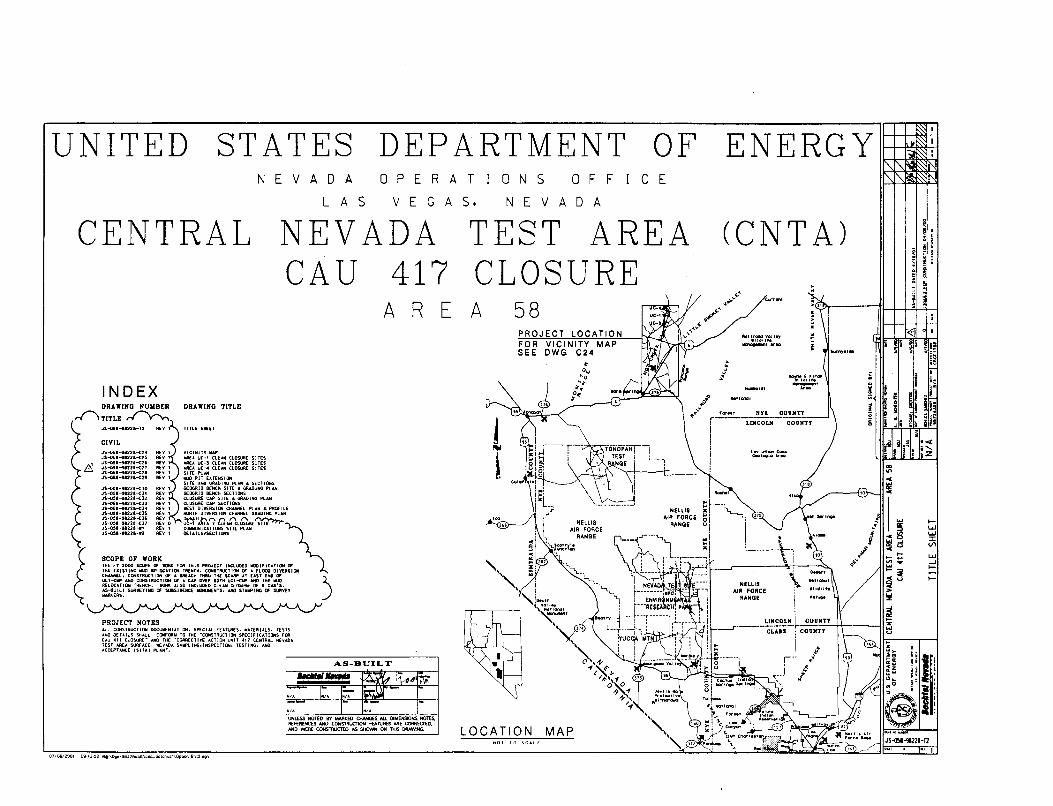
DEPARTMENT
TEST AREACLOSURE
NEVADACA U 417
ENERGY
(CNT A)
E
OFcFF
A
ooA
5
VE
NoN
A T
A 5,
R
G
OPE
V EA
A S
A 0
L
VEN
STATES
CENTRAL
UNITED
0710612001 og'2~2 Mt'''09''\i8nllo~Il\C(l4~aala\..cl\OpIlOtl 8\12<1Qt1
l.U...Jl-
I-
Il.Ul.U:I:V'l
'II.' 1JS-QII"'lI21HI
~1:I.Kf~·~f
l ... lothlin Co~,
0.01"'11110 .... eo
"clltrClOllvolt~Wll01lf,
~'ArIO
"~,,'
fer.., NYI COUJlTY Ir---L"iifCOLM-cou~IiIii
t0"'0-~~.
°t~
"-,C' '\ 1'1("{"
<,('0\\"o,,,1'''-'1+"''1
MAP
FOR VICINITY MAPSEE DWG C24
PROJECT LOCATION
58
-," ,
A
LOCATION
ERA
AS-BUILT,..,......~11'1'41 'm;'
." C, I~/A ~..lJ"- I' -." ".UNLESS NOTED BY hWlJ.ED OWrtGES.AU DIMENSIONS. NOres.Ri'FEflENCES NID COHSfRUCTJQN FEATlJAES AAE CORRECTEO.MID 'oNERE CONSTRUCTED AS SHOWN Ofrl THIS DftAWING.
.n,.."."'.IlE'l'1FlU I.., ,
CIVIL
INDEX
';~"'O!i.-t122'-T2 Ili:V" TITlE SHUT
JS--<l5.--H22.--C24JS-05.-M221-e25
A' JS-o!l'-!l22.-e2'Ll..}. JS-05,-11ZlI-<:2T
JS-05.-i.22.-eZiJS-05.-i.22.-e2'
PROJECT NOTESAll CONSTRUCTION DOCUlEIiTUICW. SPECiAl FEATURES. W,TEIlIAlS. TESTSAIr/O DETAIl.S St<ALL CONFOIlt.t TO THE ·COttSTRUCT10N Sf>EClfICATIONS FOIl(Au 411 CL~URC .uco TKf 'CllAAECTlV[ ACTION UNIT 411 CENTRAl NEV.I.OATEST AR£.A SURFACE. NEVADA SAlFLltrtG.IHSP(CTICIII. TESTltrtG. AHlIACCEPTANCE ISIT,l1 PLAN'.
DRAWING NUYBER DRAWING TITLE
.r-. TITLE .rv-:
VICIHITYlW"A,flU UC-l CLEAHCLOSURE SITESAAEA UC-l CLEAN CLOSURE SITES-'AU UC.... CLEAN CLOSUR( SITESSlTEPL.utIAIO PIT ElT[NSl(lNSITE ANO GR.101Nl; Pl"" .. UCl[OliS
.15--05'-1122'-<)0 REVQCfDCRIO BEt«:H SITE" CRAOING PlAHJS~''''''I22t-(H REv GEOGRIO BEt'lCli SECTIONSJS-OS.-11122t-(12 REv CLOSuR£ CIJ' SITE .. GRAOING PLAN.;5-05.-9.22.-<:n RiV 1 CLOSuR£ CAP S£CTIl)r(SJS-05'-'Ja22• ..(;14 Rn I lEST OIVEAS1C»t CkAHHEL PLAN" PROfiLEJS-OU""9122.-elS REv 1 IfJRIH DI'lERSIC»t CHANNEL liRAClIHG PLAN
~~:::1:~~:~~~ :~~ ~ B~l~l,} cQlH'i:lQ.ItE~'"JS~'-9112."'" Il£V I CIMlJHICATIOHS SITE PLAN :\JS~'-1l'2l1-n illY I QEU.ILS~CTl0H5
SCOPE or WORKTHE fT 2000 SCOPi Of M;Ml Fl]fl THIS PROJEct lliCLUO€D IOllfiCU10H Of
<~ '" "''''He ..., .n""".. ""CH. ''''''''''''''' OF , FeOOO "'''$I'''CHANNEL. CONSTRlJCllClHOF .. BIlfACH THItU THE SCARP AT EAST [NO 01
UCt,'" AHO CONSTItUCTlON OF " tAl" OVER StlTH UCI-eloP AHD THE IoIJO )RELOCATION TREItCH. IIOfIC AlSO lltCLUDED ClE,," ClO5lJft£ Of li CAS'S.AS-eUllI SUftYEYIIiG C* SlBSIOOIC( WONUWEIiTS. AMD ST.... 11iG C* SUltVEV.......ERS.
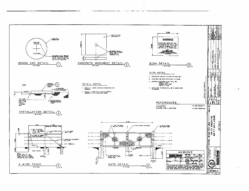
V'l....<C(.....UJ0,
JS~~-"
III
i
I~~- '"'i~t... ""~VI ....... - ........ -~'i~>'"'S~
~~
'"'
e
:1 1e !i u
~
<l3~
EI ~I ~r§ ~ e '-I... ij~
; I II
i
JS-058-99228-T1
JS-oS8-99228--ce
~__ Il!rr,I",
AS-BUILT
1
lINL1SSNOTED IV loINlaD OtAHGf$. AU. DlMENSlOfo&. NOTES.F\f.FEAfHCtS AND COHS1'RUCT1OW FEATUAU AAE cOfIRErno.AHtJ WERt COHSlHllCTED AS SHOMlf ON 'THIS DfWMHG.
16211I
a- (Xl GATE POSTAICl COltHER POS'
r
TITLE SHEETCLOSURE CAPCRAOINC PLAN" SECTIONS
REFERENCES
[
WARNINGPETR1UUW Ilf'ACTED SOIL.
;a NO EXCAVATIIlH. DRllllNC,i! AND/OR REWDVAl CF THE::: lIATERIAlS IS PERWITTED.
-~,
t.~==~• .'._"".=1 '"I_•.• ·"'1\1, ........
SIGN NOTES
1. lIUS O£TAIL ""PllES 10 SIGHS l»iI fENCE DHLY
2. SIGH SHAlL 1£ WHIT( .ITH 8I..ACIl. L[TTUU.....
, ...IHI ..... lETT£Il/llORO HEIGHT $HAll 1[1OAHGlR • TS'"I~DIllllAflON • ,....CONTACT - "..,
4. 510101 srccc tHI(;INE$S S..All I[ " liltGE./O.OilSOR CltEATEIt
........ , DETAIL
LAtCN ~EEP[R .lIj) GUIOf
loft tiRtcAsfI
IN SUAVEY SHALL
jill , ~.
CAST-lhI-f"LAC
IRILL HOLE &. EPOXY8AASS CAP TOCCNCRET£ DISC
I":/\T,," DETAIL
9 GAUGE IIR[ lIIt:5.Hr ABArc OA ~ STRANO8AR8£011RE
.~?NUMENT DETAIL (~\
1'1 I \ ~ r+i' • IF • ! ',Hi I '>l~ ~-----<-l.-s.xxx\ lH 1-1 X" " La
DETAIL NOTES
1. DEtAil 2 - :iIlOWS CONtIlOLl[O OIIll[~IClNS fQll/,()NU\LHT.
2. DEU!L 4 - fOR.. CAST-IN-f'u'C£ COHCRET[lIIlNUIoI:HT TO THE OlwENSIONS SHOWN.
!
CONCRETE
J. 00 CORHEAPOST (n!")
, GAUGE NUl GlLVAHIUDsnEL I,RE
'lsl~:p
IN ~UflVEY SH.....L PftOVACTUAL WEASUAED ..... ALUEAFTEA IhiSTALLATiON. SE.Eo.c CI FOR LOCATION
ORNEIl OR TEIblINloL Po\IIl£L
305*1 I
1.5211I 1.5211I
i II \ ,II. "'"'C ll--"•. 'UllMlUC'LE
INSTALLATION DETAIL ~"
~~._- "".,p DETAIL
NOTEISf CURE liRE TO LINEPOSTSANOPULl,t,lll)JhIOCOI'INER POST IITH[HOO.JCHT[hlSION TO AVOID SAGGING
A \ ...1 r or= FENCE
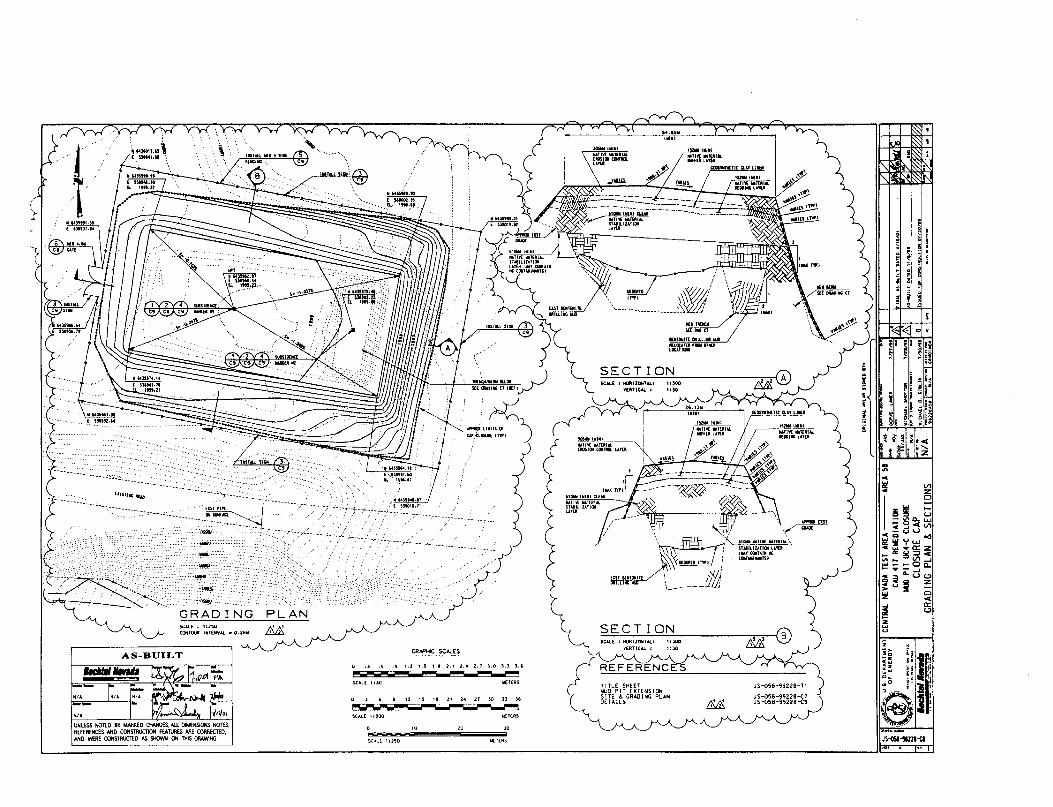
'I'
!i '~'<ii ~ r~ I ~ j;lil' ~ ~!:Ii ~ i~;:
JS~-lIl2H'
..'"i ~
I0
~~ S-lSD.. W~-'c(V"»- ... U""0 ..,
~~~~Z.. Q:~:::l'"V').- lJ'")....J
"""- ..... 00........ -....J4: Q.. U O~B'l ::,.. :II Cl':l! ...
~ ffiztJ
Js-osa-99zze-T1 ?JS-058-9Cj228~~ )JS-QSIl-9<j228y
111-
~\-&; "':! ,-""."\( , .....""'--~
't\\\ f """""',,~~""\Jl.\\ """" on" : ~; ..To" '" '"" ",: : ..,-,,,
L " ,'1,/1'c.._----Ij!JJ
;,,~,:,:,:,0 ~oo ~ ®V£RTICAL I 1:30
(
R E F E R-E N e
TITLE SI'iHTMUD PIT EXTENSION
. SITE & CRADING PL....NDETAilS
·--(FlS
GRAPHIC SCAlES
(I 10 10 JO
-=5C'LE 11150 METERS
'"......L~ 11]0
SCAlE llJOO
(I .5 , j 12 15 HI 11 l4 H JO n ]6
,..,.._____ - - --..---.I
AS-BUILT
'I'UNLESS NOTED BY MARKED OW«iES,ALLDIMENSIONS. NOTES.REFERENCES AND CQNSTfIUCllON FEATUftES ARE CORRErnD.AND WERE CONSIftl/CTED ASSHOWN ON THIS DRAWING
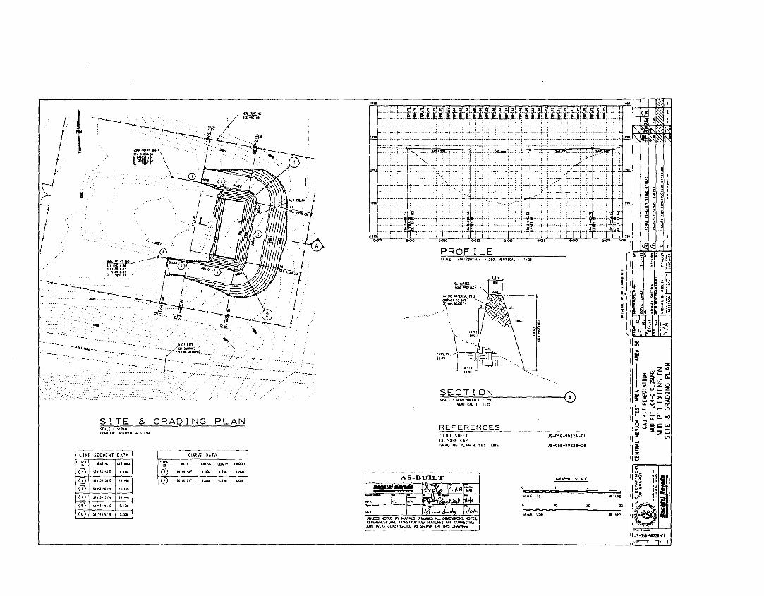
•~II§I
~
~I ~
~:I'
~
~r' -E~' ~II~~ ~ ~;ii... ... .... i~1
JS~-1I21Hl...,,, ....
... ..,. ....'I~ !i) ~ ....i t r! ;~...'"4-
~
I:z::z:<C
~!5~~-V'>V>
3d~~oIIl(o 1--_t!ljj'l'xClCw.I .. uJ<... "'!5 a::Ioht- t-O
~;~o:"'"c",o.
:~~§~~ :::E
V>
g~
~
i;~
!i
!e
"W£l(RS
20
JS-oS8-9922B-Tl
JS-Q!lII-l!i22fl-ea
GRJrPI1C SCN.E
~Ii.~
1125
sou ';2~
SCALE 1·2~
ill:::.=~lli",.I 11;:;::1 II=- "'"
.....---~
TITLE SHEETCLOSURE CAPGRAOING PL"N &. SECTIONS
'.'111liiii
REFERENCES
(LnltIU11ft PUlL£)
PROFILE5CALE I HQIlUCIt'l"ALI 11250. V[ftllCM. I
Il'TlVl IM.TUlIM. fiLLCQIII'.tlroto'l '1J"~\lEll$ln
'\
.. ' \'\
SES~l~~ 0...lUICAL I ','IS
19~.U
mtl
AS-BUILT
lttt
"..
..'HlEllii
... """
CURVE DATA
~l Pllll , IlAI)IUS Il1JllOTK I 'lIliGon
01 n·s,'s,· ~ '.0511 j 4.'" j '.l$II
01 ......". I'·"" 1""'1'·""
~"4\.t • IllS"COMrOUR IMlE.IIV-'i. • O.l!l~
,
LINE SEG~ENT DATAllUI:IlT aUlllte DISTAIlt[
"0 5"''''14"(; •• 1....
0 Sl"WS~"( ....~0 ,,1l'Z4'CU', '.. '~0 SWn'ss·. 1'4.4!.ll
(,) H,-n'SS'f I '.IOll
(') !la"4nl" '.mll
t
I
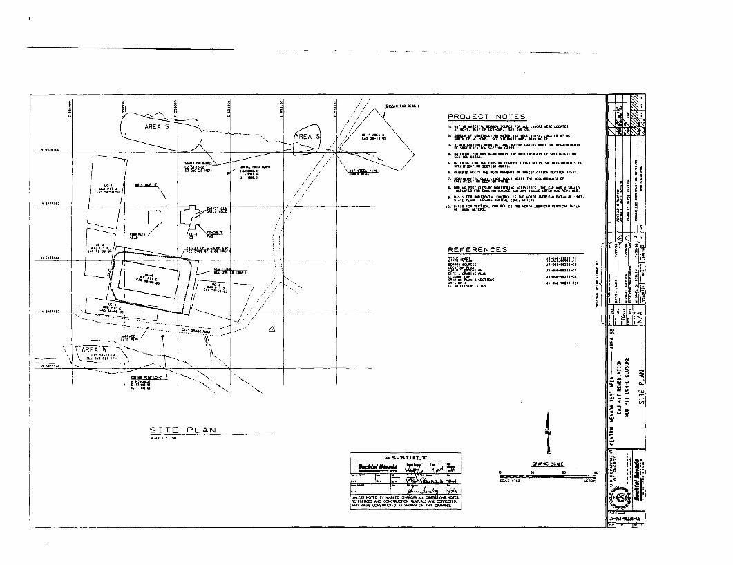
~--"c...........VI
!i '~'<8 1 ~::.-I ;; ii I : jS~~ B:II II :II i ..
= i ~ ~ i.e.,' ~. 1'; i lZ
~
.1 ~I!
..'"C~
I~;- ucQ
... ~'l'~lI!"- g"'-~;=;~:>u S~
2~u
.~
WETERS
JS-o!I.-H22t-T1JS~'-"221-C:'"S-05,-tuzao-Cit
oI5-05'-"22''-<:J
J$ ..OSl-tt2Z'-<:'
JS-OSl",UZ'-(ZJ
1CRWI4IC SC....E
SCALE \17~
PROJECT NOTESI. NATlY[ ...TlAUl. ICJWJII 5QUlIltr JOlt All LAf(A:S '111:11[ LOC...1U
A1 UC;-1••51 Of UCl-C~. S[£ 0" CS.
2. SOUItC( OJ tlJrfSnllUCTIQIiI lIAfUi wAS 'lllll .. TIl-2. lCKATlD "T UCt.SOUT.. M UC1-.a1t. K[ VIClliilTY ..... _ ••lIilG Ct.
J. STlIJlIUTIClii. KOOIMG. #MO IUFUlt LAytJtS lIIlU1 THI: IIlQUIJI[WN"OJ SH:CIFlUTlQN steT"'" oun.
<t. IIlATtIllAl FOlt tr€w .Mia ..'n 'hII. M:QUIM."ns 01 WlCIFICATIIIISECTlClil 02223•
t. ""T£II'I ..... FOR THE EItOSI(JIj CONTML lUE!l iIlETS THE M:QijIJl[lEN'S 01WCI" IC...TlClil SECTIQIII ClZ"t.
t. CiEQGltID t«lTS THE "lOUI."",, Of Sf"EClfIC'TION MCTlO/Il 01551.
t. C[O$VN1HlTlC CLAY lINlII IQCLI WEn TIC J1fGUIII[IiOITS "S~ClflUTIQIII SECTION 0151••
•• DURING PQ5T Ct,OSUAE WOfIiITOltING .t,CTlVlTlES. TItE til' .AS VISUALLYIN~EClEO FtIl EIt05ION 04lllol.G( 1M) MY O,*," liOTEO .., R£' ... lfIl£O.
t. =~1U ~~~?":J~.J:a-ci~~:t'"Z~~HEWEg~~~IIICM DUUIIl Of '111.10. IIASIS FOIl VEATIC.... CO/IlflllCl.. IS TME IOlTIt _IIIC.... VUTIC .... DATUllI
Of lU'. IIf;TERS.
;AIl.EIIl pAD OUA
<,
AS-BUILT
uc.......... 11CAS SI-10-ge
'~'",~
L1!.
/1/
allTIIlJ,.I'OIlIT~."
....:MOIO.!l( ntOH.Hu ,,...u
"'-"',,--...
1li[fll
LH;~n:
...~
". ,.'" I "<,-------".","'",. ."<,
-, -.,
~
SCAlE l 11150
SITE PLAN
tomllI.I'OIlT IM-<....ntn.l1E "1"".11[l, '"'.01
"'-'"
--_. ~j--~~~~!-h---- ----.h t----/:/._--___ ear -----.------~~. .-- .... __ __ GlltNCL~ •• ~~
- ... -......' . ~ ---------~-----------~ ...L \;.
---.... 'k..---.. , ~ .
\
1r164l5950
"".36050
,.. '''''000
N '''3'100
M~OO
./HII'1ll1t-Ci
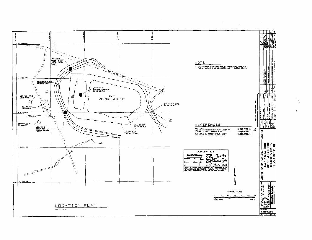
lllETER5
100 12010eoo 20 40lOiiijI
GRAPHIC SC....£
AS-BUILT
TITl[ SHEETlILlO PIT un.NS1QN C«AOING I"lJofil .. SECTIONSC,,05UA£ CAl' SIn: .. fii.Il:ADING ~AN
IlEST DI'lERSll:l\l CMANNEL ~AM &l"flaFll[UU OI'l£ftSIOIiI CIiAMNll GIlAOINU Ill ....
REFERENCES
NOTE
...,.,.... ~,_ n.", Fi:i:C. I~. Ii:e ~~ .l,/Jo/.I
---,------
-- --- --- ---
SCAlE: 1 :1000
LOCATION PLAN
------ ------ ------
f-----/:':/
//
,.):/
" ,.·<1]0.100
(( 'In' OIYPit~~ E&.\\ KlOllUtIIlUI -
\\
-,~....~"\\~ :~~'.". J~t(\
W!II-ilI-OI \~\\N '.4]0, 100 io--'--';\~
M ,.UO.tOCl
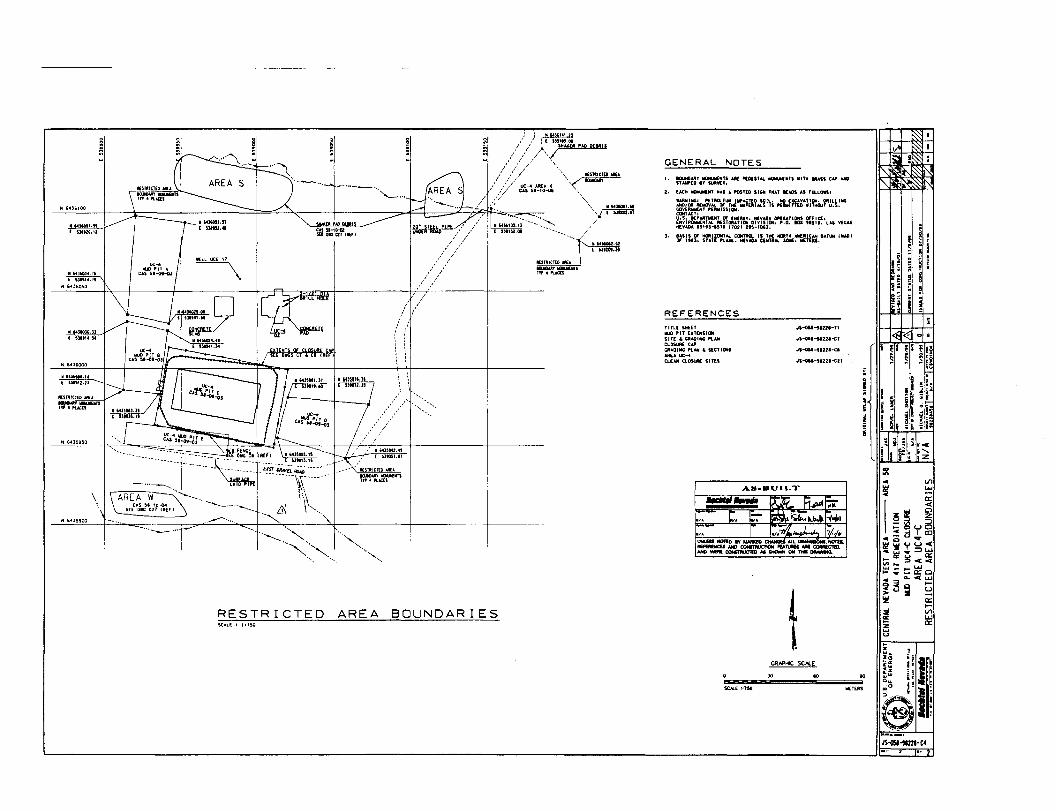
1II1"l11~
-0ll'n
OU
I
_..J.>_..........
'.....ll,lIC
IUlJM
Sll'ftO
lI1
y1./0.
O~IS
..
OU
Rln
I"llIID
V/N
ur,,,,~
S3[~VONnOg
V3~V
031JI~lS3~
J-~Jn
V3~V
]ljf1Sl)1J
:H:lfl
11d(J1
I
P()I1YIO~3Hll~
nYJ
ssY3lIY
---
Y3lIYIS
]1YOY~~
1YllIN
D
~
VI
WUZWOCWILWOC
Vl
W0:4:oZ::Jo([)4:W0:4:oWfU0:fV
lW0:
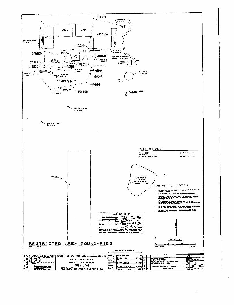
"HIUlI'ITA
.UHiI'IL{-ClIlSf.CC15"I-,.-o1
~ "-Xno.-42 ~._----.__.._.
( ~,..t!I.,7
r-=I~
~' - """us .........
0:-'.... "
~II.STEI'IL£-a.os[DCASsa ..... 4
REFERENCESJS-Q58-98228-T1
JS-QS8-98228-t26
..GRN'NC SC.....E
GENERAL NOTESI. ~ •••lUrs.P£D[ST"IIOI.IOJS'llIllltlSStI'_
STMfIQIT 5UIl'W'E'f.
2. UDllDUlJll IUS .. PmttD SIIIi 1IYoT 1I:Ml5 AS'II.LClISI
....e: fl(ll11.[lliI I..AC:TU SOIL_ • uc'Vl.m••• ILl ....
...1OlI1IODI'.... lFTlI:WOmtl....SISI'EWITTDlIITIQ/TU-S.~1'[.ISSI...alfu,,~
U.S. II\I'M:nOT fI Dl:CT. lPoII),I,(ftMTllll5 !fHa.Dn'1..-:1I1Al II.nCfI."lIJil OIYISllJI. P.O....SII. LoUw:m.,••,u-.s1' Hill m·lQU.
3. WIS ••'laOll coma. IS .. IDml IIIOIC_ 1to\'f1Il ._.llfl.",SUflllL•• Il,aDf.ClIfTIM,.U..llftllS.
... ILL 'MS1I '1LU ... a.DSm. LOtIITlOIIS.., FGIl lEaJIID......., ...,.
TITLE SHEETAREA OC-3CLEAN CLOSURE SITES
tAIt.£U'
RESTRICTED AREA BOUNDARIESSCAll I 1.l!lO
OJIIGI..... wn.... sr_D 1"1.
.II@U.' DEPAA'WENT CENTRAL NEVADA TEST AREA --- AREA 58 ,-J ..
Of (NEAGT ..... OCI"J'l.L....lII lnr".,CAU 411 R[I£DIAT1lJj
IUl PIT UC4-< CLOSURE ~".s lllIC"'AlL Sl«JT1D11 In..'''."."._T,__,"AREA UC-]
....__._... _........... ... ICIlAll e. el.... IN
•. a __, ... _ ... _ .._1" RESTRICTED AREA BOUNDARIES N/A __rt_O ~_ • ,.""~llTDdto4lt1Jt'lI( _ lilt
QlllDT STaTUS il'J£t "11'"
IS D,.QIl C0lllS11I.ICTI or"on•
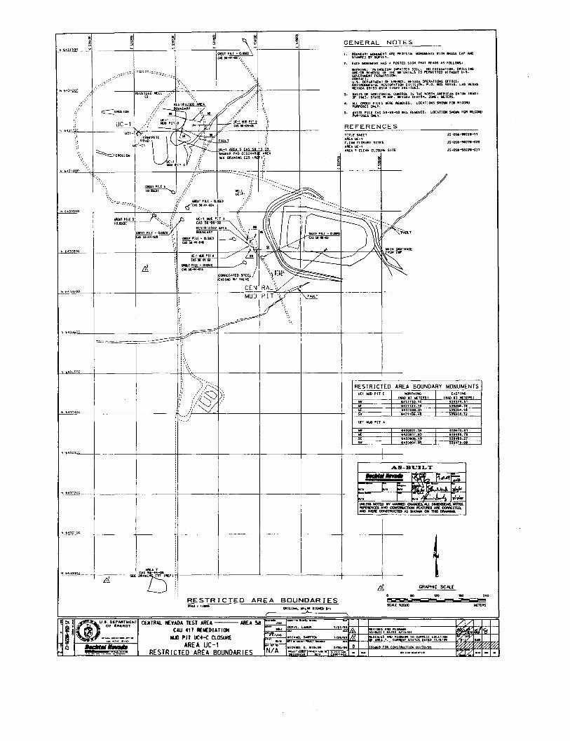
GENERAL NOTES
I. llOONDART IIIlNlIWEIiiT ARE l'EOESTAl .OU'IUns .,llI PAs.s tAP AtClSTAWED 8Y $UR¥[T.
2. EACH IDiII..IIIlENT "OlS .. POS1£D SI(;H THAT READS AS fOllOWS:
PETRCUUM '''''CTEO SOIl.. NO £llC"......TIOH. DRILLINGWVAl OF THE. IMI[RIAlS IS PERWllTED WITKWT U.S.
PERWISSIOH.
NT OF [HE";'. NEV"OA OPERATICJfS OFfiCE.RESTOfUTUI'. DIVISION. ".0. acx !8~'" LAS VEGAS
-IS1' (l02) 295-1063.
3. BASIS OF H(IUZO"''''L tmITRDL IS THE NOFlTH oUlfAlt»l DATUIll IN.lD1OF "'3. STATE PLANE••"'AOA C[NTRAL lCJrlE. llIlETERS.
4. .....l GROUT PILES 'lERE 'IU.)VED. lOCATlClllS SHOWN fOR RECQIIlD~OSES tN.T.
5. W"ST[ PIU CAS 5'''''~ .... S R(IIlllVED. lOCATJ(IiI SHQ.. fOR MetROPURPOSES 0Nl Y.
s ~ ~ ~
~g ~!
~ ~ s ~ ~N 64]\300 ~ ~ ~ ~ ~ ~
allIT"U -Q.05lDCAS$1-44-(6,\
\\\:~"// "
REFERENCESTITLE SHE£TARU UC-1CLEAN CLOSURE SITESAAU ue-1ARE' ,. ClEAN ClOSUIlE Sift
"S~-"22'-1'
JS-05.-9122.-c25
JS-051-11211-e31'
~ b~]0700
tA$H-G!-02
GIlWf "Ll - a.OSQWM-44-ol'
RESTRICTED AREA BOUNDARY MONUMENTSUC1 lilJD PIT [ I (1IIf.O~)TH~~[I'SI I (1U.D[~T~ERSl.. ...31UO.10 539324.51IE 5431123.11 ~"3~'.1.SE 1431088.01 ~3'3~4.1!1
s. 1431105.45 ~")14.12
"S.
1430831.)56430131.151430805."14301104.':i
5"410.11~39..... 1'~"4t9.21
!U'4n.oe
II
AS-BUILT
N '~J0200
........ ~11,,~~
C. E:- ~'IC; ~
to£T[1tS
.. '40II"""""!
/1/
%I~I... I
rzrzi- -I-
GRAPtIC SCAlE
$C.'U .2llOO. ..t"1
'''''00'91 0
AREA 58 I JiLl _,'TD --~OCJI'I't:...AMUl
QIlIGI""'- MYl" SlllIl£D In.RESTRICTED AREA BOUNDARIES
CENTRAl. NEVADA TEST AREACAU 41T REII:DIATIlIl
IIJD PIT UC4-e ClOSUREAREA UC-l
RESTRICTED AREA BOUNDARIES
I ~ ; G)u.a. DEPAATWIENT~ , II Of ENEROY
. ~ i .. ,__..
Ii ...""....
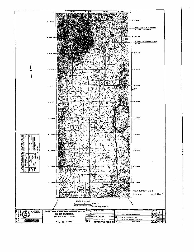
JS-051-99221-11
WATERSOURCE OF CONSTRUCTION
SOURCE OF BORROWNEW DIVERSION CHANNELS
IlTlE SHEET
REFERENCES
......" ....
ISSU£O '(11 CONSnlJCflON 011 o/n-.u' ........,,_ •, 21 N/'" ," -4
un~£
MICHAEl. SMOT1D11 U2tJ'H
,..
N/A
I .......
GRAPHIC SCAUo :5 IS lILow[TiJtS
ct.",. IITl'rAt U It{HItSC1tIGIMAL am.M SIGJCD .",.7
VICINITY MAP
CENTRAL NEVADA TEST AIl[A --- AREA ~CAlI 41T REI£DIATI[Jj
IU) PIT UC4-e CLOSURE
~ ~ rG)U.a. DE"P'AR.TWENT.... II: OF ENEAQY
~! :,; ..__ _ .. 6 ...""....
.... __ , 'U __ .._~
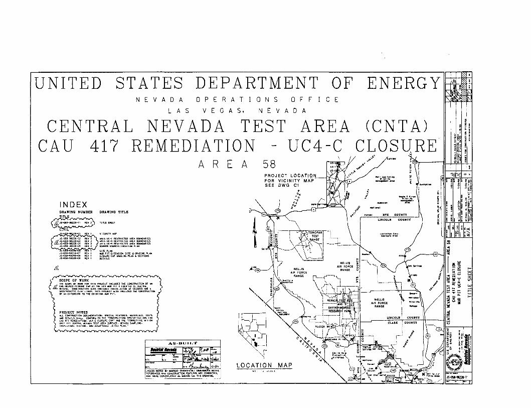
I-
.....--'I-
I..........::I:\I')
JS~-lt221-T1
l •• IOfflllnCCPf.v.G1OOla ""'10
NTI COUNTY
LINCOLN COUNTY
hi .rOOd Yall.,"tillite;_~N
ENERGY
rI;
..5-·;~.
8 i:__ ..__.\--,
\i
(CNT A)CLOSqRE
NELLISAIR FORCE
RANGE
E
OFcF F
A
oD
AREAUC4 C
A
5
V
58
o N
N E
A
LOCATION MAP
A T
A 5,
ERA
OPE RV E G
DEPARTMENTA D A
L A 5
V
AS-DUILT..,......~\i , 111'~ ~11l
'" C. I~. I~ ~ .~ -,.J"
"I- N/~ i. ..,/1 l/fJ I
~S:~~~~~TvAES~C::~.S.AND WERE COfIlSTAUCTEO AS SHOWN OH nilS DAAWlNG.
EN
STATES
s -lJt e-c ,.,15-05'-1121.-<7 IlEV 1.,15-05.--1122.-.<. REV 1JS-oS.-'itl2t-<:. REV 1
DRAWING NUIIBER DRAWING TITLE
.r~~~ .,IS-Q5.-t.lU-Tl It[~ TlTL[ SH£U
~,.."'-c,""'.;r;:.,;......r"...''''''"\. v ICUIlly ItW'
...u:. lIC-1 RESTlUCTEO Mit ... OOUNOo\AlESAIlEA UC-l RESHliCTED AREA BOUNO.t.A1ES"REA UC-4 R£SlRICTEO IJttA BOUrOOAA1ES8OIUlOI SWAC[S lOCATION. ""-AN
SITE PLANlIIJDPIT ElITE/riSIOH. SITE .. GRADING Pl.","CLOSURE CloP GR.+.OIJrfG Pl ..... SECTIONSDETAILS
INDEX
PROJECT NOTE."LL CI>lSTIlUC'1OH OOCUt.IEhlUTI(JrC. SP£CIAl FUT\JII:U. ~TERJ"lS. TESTSANDOElo\lLS ~Al.L CONFORW TO THE ·CONSTRUCTIOH SP£CIFICATlt»lS Fl»!:C~U 4'1 R£Iil£DI~1ION, UC4-C CL05Ull[ CAP· ANO TH[ ·CORRECTJYE ACIJONUNIT 411 CENIR.t.l H(y.wA TEST AIlEA SUflf'A(;E, H(.YADA SAIlfI1.1NG.INSPECTION, T[STIHll. AND ACC£PTANCE ISIT"1 PLAN,"
PROJECT LOCATIONFOR VICINITY MAPSEE DWG Cl
(r' SCOPE OF WORK
THE SCOPE Of WORI fOR THIS PROJECT lNCLUO£O THE CONSTRUCTION Of AN~) ENCINEERED CLOSURE CA# .u THE UC4 IollD PH C LOCATED /JolCENTR"l.~ NEVADA. CONSTRUCTION "LSO IHClUOf:D INSTAlLATION OF CiEOGA10 oIJ4) A
GEOSYNTHtTIC (LAcV L1NfR. THIS PROJECT J.l.SO INCLUOED 116': Ct»lSTRUCl([»IOF ..... [XTUlSIOIl TO THE EXISlIMe MAl PiT.
CENTRAL NEVADA TESTCA U 417 REMEDIA TION
UNITED

This page intentionally left blank
..,
,......i,
r,,
APPENDIXD
SECTORED HOUSEKEEPING SITE CLOSUREVERIFICATION DOCUMENTATION

THIS PAGE INTENTIONALLY LEFT BLANK
•
:III
J)
III
)..J
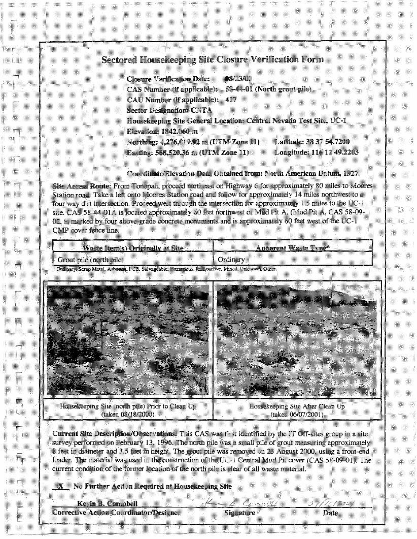
Ladtude: 38 31 54.7200Lnngimde: 11612 49.2203

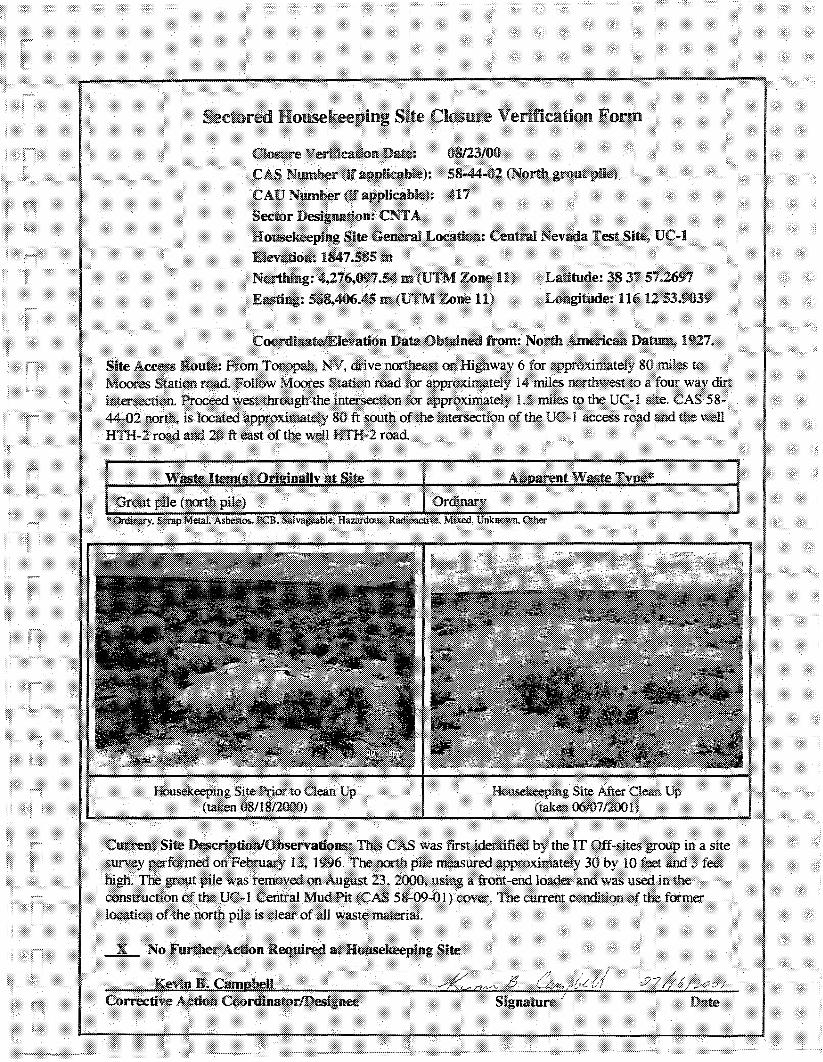
Latimde:383757~97
Longitude: H6 12 53.0039
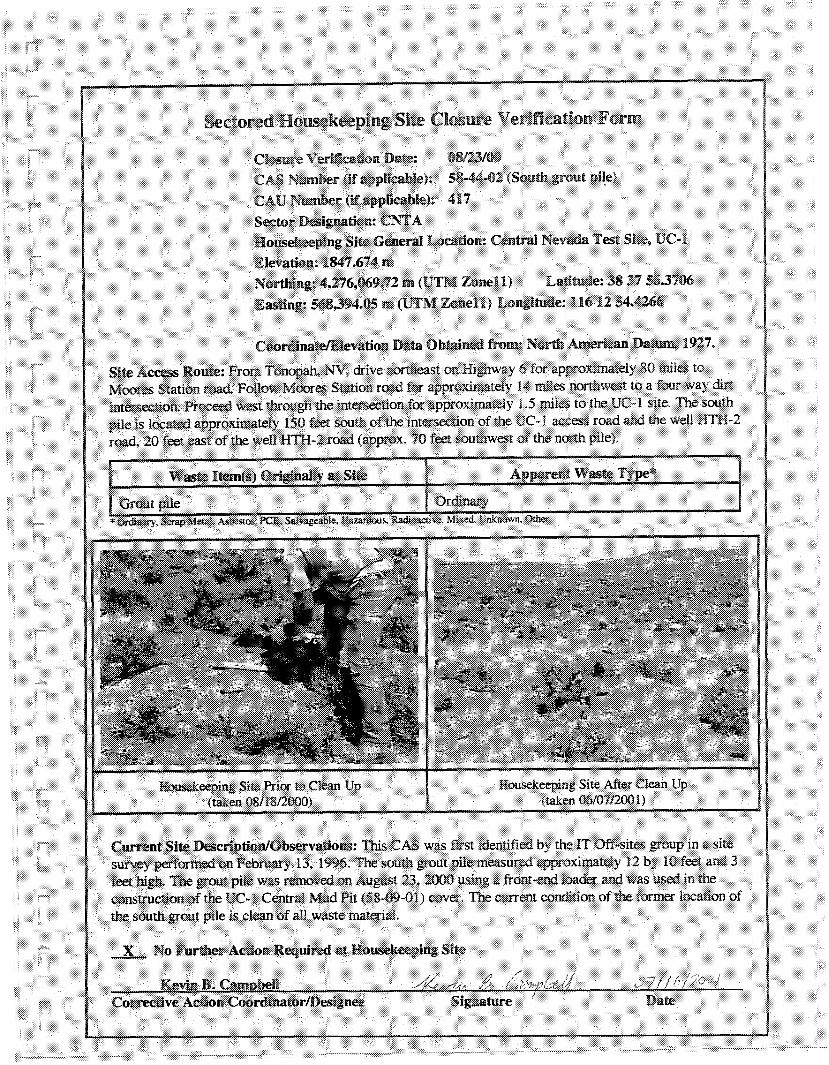
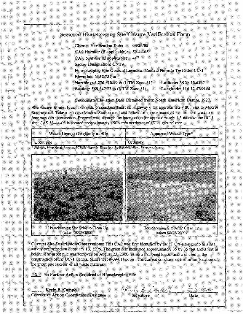
Latitude: 38 3810.6261Longitude: 11612 41.9144
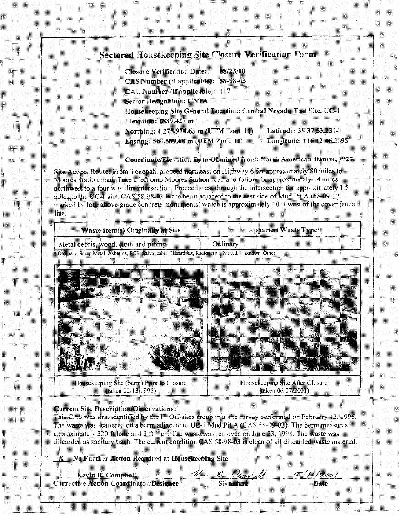
Latitude: 38 37 53.2314Longitude: n612 46.3695
Date
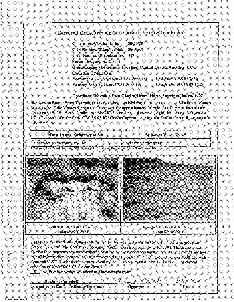
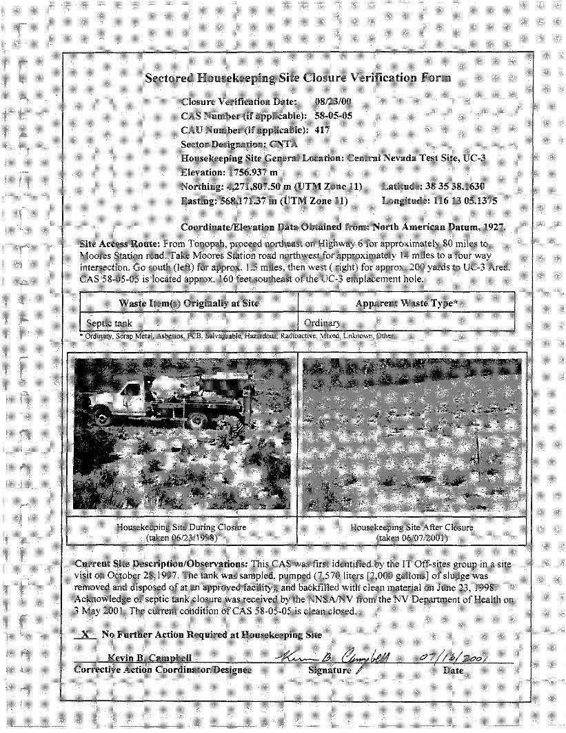
Latitude: 38 35 38.1630Longitude: 1161305.1375
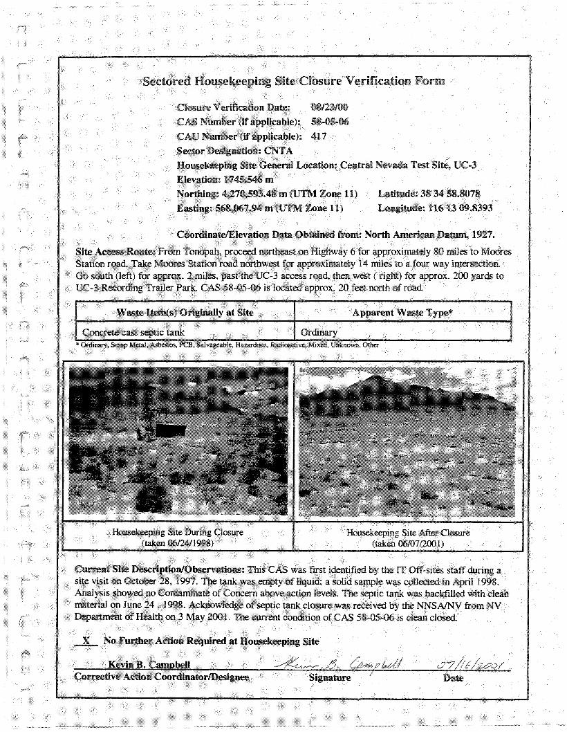
Sectored Housekeeping Site Closure Verification Form
Latitude: 38 34 58.807S
Longitude~ 116 1300.8393
08123/00
58..fiS*06
417
Closure Ve.ri5cation Date:
CAS Number (if applicable):
CAD Number (if applicable):
Sector Designation: CNTA
Housekeeping Site General Location: Central Nevada Test Site, DC*3
Elevation: 1745.546 m
Northing: 4,270,593.48 m (UTM Zone 11)
Easting: 568,067.94 m {UTM Zone 11}
CoordinatelElevatron Data Obtained from: North American Datum, 1927.
Site Access Route: From Tonopah, proceed northeaston Highway 6 for approximately 80 miles to MooresStation road. Take Moores Station road northwestfor approximately 14 miles to a fOUf way intersection,Go south (left) for approx. 2 miles.past the UC-3 access road, then west (right) for approx. 200 yards toUC-3 Recording Trailer Park CAS 58-05-06 is located approx. 20 feet north of road.
Waste ltem(s) Originally at Site Apparent Waste Type*
Concretecast septic tank Ordinary*Ordlllllfy, Scrap Metal.Asbestos. PCB,Salvageable. Hal.IlTdous, RadIOactIVe, Mixed, Unknown, Other
Date
Housekeeping Site AfterClosure(taken06107/2000
Signature
Housekeeping Site During Closure(taken 06/24/1998)
Current Site Description/Observations: This CAS was flrst identified by the IT Off-sites staff during asite visit on October 28, 1997. Thetank was empty of liquid; a solid sample was collected in April 1998,Analysis showed no Contaminate of Concern above action levels. The septic tank was backfilled with deanmaterial on June 24, 1998. Acknowledgeof septic tank closure was received by the NNSAfNV from NVDepartment of Healthon 3 May 200 I. The current condition of CAS 58*05-06 is dean closed,
-L No Further Action Required at Housekeeping Site
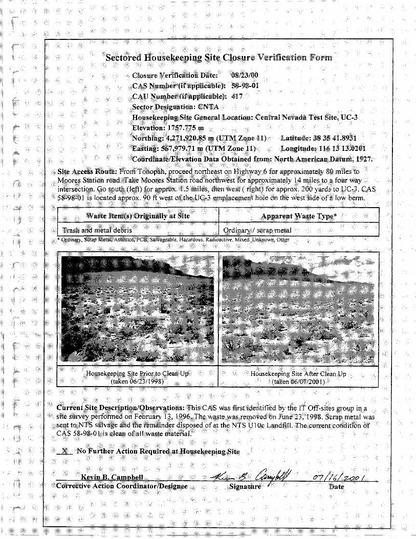
Sectored Housekeeping Site Closure Verification Form
Closure Ve·rifitation Date: 08/23/00CAS Number (if applicable): 58-98-(}l
CAD Number (if applicable): 417
Sector Designation: CNTAHousekeeping Site General Location: Central Nevada Test Site, UC-3Elevation: 1757.775 mNorthing: 4,271,920.85 m (UTM Zone 11) Latitude: 383541.8931
Easting: 567,979.71 m (UTJ\!l Zone 11) Longitude: 1161313.0201CoordinatelElevation Data Obtained from: North American Datum, 1927.
Site Access Route: From Tonopah, proceed northeaston Highway6 for approximately 80 miles toMoores Station road. Take Moores Station road northwest for approximately 14 miles to a four wayintersection. Go south (left) for approx. 1.5miles, then "vest ( right) for approx. 200 yards to LJC-3, CAS58-98-oJ is located approx. 90 ft west of the UC-3 emplacement hole on the west side of a low benn.
Waste Item(s) Originally at Site Apparent Waste Type'"
Trash and metal debris Ordinary! scrap metal,.
'"Ordmary, Scrap Metal.AStlCSt05. PCB,Salvageable, Hazardous, RaUINICtlve, MiXed, ~Jnknown, Other
-X.- No Further Action Required at Housekeeping Site
Date
Housekeeping Site AfterClean Up(taken06/07/2001)
Signature f
Housekeeping Site Prior to CleanUp(taken06/231199&)
Kevin B. CamQbeU
Current Site D~cription!Obsentations: This CAS was first identifiedby the IT Off*sites group in asite survey performe.d on February 13, J996. The wastewas removed on June 23, 1998. Scrap metal wasfie,nt to NTS salvage and the remainde-r disposed of at the NTS UJ Oc Landfill. The current conditionofCAS 58·98·01 is clean ofal! \vaste material.
Corrective Action CoordinatorlDesignee
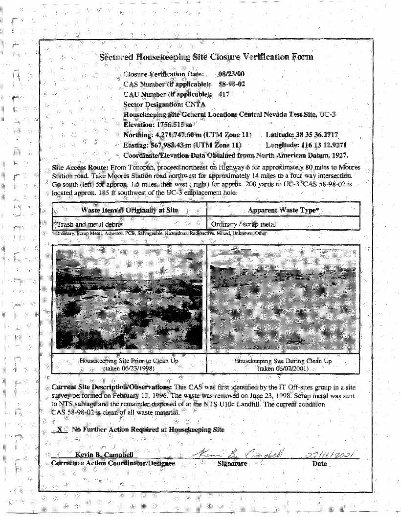
081231005&.98-02
417
Sectored Housekeeping Site Closure Verification Form
Closure Verifieation Date:
CAS Number (if applicable):
CAD Number (ifappUcable):
Sector Designation: CNTA
Housekeeping Site Genera! Location: Centrm Nevada Test Site, UC-3
Elevation: 1156.515 m
Northing: 4,271,747.60 m (UTM Zone 11) Latitude: 38 35 36.2117
Eastlng: 567,983.43 m (UTM Z-one 11) Longitude: 1161312.9271
CoordinatelEievation Data Obtained from: North American Datum, 1927.
Site Access Route: From Tonopah, proceed northeast on Highway 6 for approximately 80 miles to MooresStation road Take Moores Station road northwest for approximately 14 miles to a four way intersection.Go south (left) for approx. 1.5 miles. then west ( right) for approx. 200 yards to UC-3. CAS 58-98-02 islocated approx. 185 ft southw"eSt of the UC-3 emplacement hole,
Waste ltem(s) Originall)' at Site Apparent \Vaste Type*
Trash and metal debris Ordinary I scrap J:neta1.
Housekeeping Site Prior to Clean Up(taken 06/23/1998)
Housekeeping Site During Clean Up(taken 06107/2001)
Current Site Description/Observations: This CAS was frrS! identified by the IT Off-sites group in a sitesurvey performed on February 13, 1996. The waste was removed on June 23, 1998. Scrap metal was sentto NTS salvage and the remainder disposed of at the NTS UlOc Landfill. The current conditionCAS 58*98-02 is dean of all waste material.
-L No Further Action Required at Housekeeping Site
Kevin B. CampbellCorrective Action CoordinarorfDesignee
~~~-''''''-'''''······'''·".""w······'····
Signature
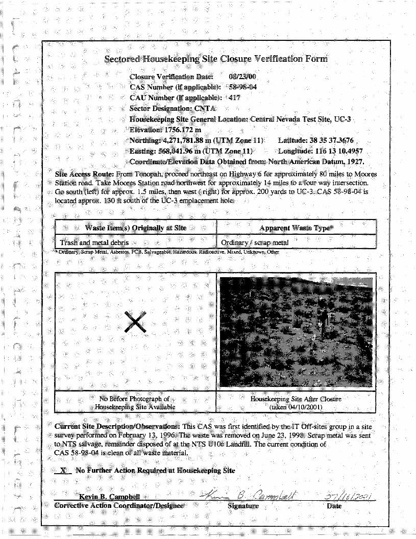
Sectored Housekeeping Site Closure Verification Form
Housekeeping Site AfterClosure(taken (4/1012001)
Apparent Waste Type*
08/2310058~98-04
417
Ordinary 1scrap metal
NoBefore Photograph ofHOusekeeping Site Available
x
Waste ltem(s) Originally at Site
Trash and metal debris
Closnre Verification Date:CAS Number (if appJicable):
CAU Number (if applicable):
Sector Designation: cmItHousekeeping Site General Location: Centrnl Ne"ada Test Site, UC*3
Elevation: 1756.172 mNorthing: 4,271,781.88 m (VTM Zone 11) Latitude: 38 35 37.3676
Easting: 568,041.96 m (trTM Zone 11) Longitude: U6 13 10.4957Coon::llnat.elEle\'lltion Data Obtained from: North American Datum, 1927.
Site Access Route: From Tonopah. proceed northeast on Highway 6 for approximately 80 miles to MooresStation road. Take Moores Station road northwest for approximately 14 miles to a four way intersection,Go south (left) for approx, 1.S miles. then west (right) for approx, 200 yards to UC~3. CAS 58*98..04 islocated approx. 130 it south of the UC*3 emplacement hole.
-L No Further Action Reqwred at Housekeeping Site
DateKevin B. CdlmRbell
Corrective Action Coon:JioatorlDesignee
CUJ1"eDt Site Description/Observations: This CAS was first identifiedby the IT Off-sites group in a sitesurvey performed on February 13, 19%, The waste was removedon June 23, 1998. Scrap metalwas sentto NTS salvage. remainder disposed of at the NTS U10c Landfill, The current conditionofCAS 58-98-04 is clean of all waste material.

Sectored Housekeeping Site Closure Verification Form
Cool"dinatelElevatkm Data Obtained from: North •.\merlcan Dat:1.Jm, 1927.
Site Access Route: From Tonopah, proceednortheast on Highway 6 for approximately 80 miles to MooresStation road Take Moores Station road northwest for approximately 14 miles to a four way intersection.Go south (left) for approx. 1.5 miles, then west (right) for approx. 200 yards to UC·3. CAS 58-99-01 islocated approx.. 150 ft east of the DC·3 emplacement hole.
Latitude: 38 3S39.7923Longitude: 116 13 04.6936
Apparent '\VasteType*
08123/0058-99..01
417
Ordinary f scrap metal
Closure Verifieatkm Date:CAS Number (if applicable):
CAD Number (ifapplicable):Sector Designation: CNTA
Housekeeping Site General Location: Central Nevada Test Siu; DC..,3Elevation: 1757.074 mNorthing: 4,271,857.81 m (UTM Zone 11)Easting: 568,181.68 m (IJTM Zone 11)
Waste ltem(s) Originally at Site
Underground storage tank ..55 gallon drums
Housekeeping Site During Closure(taken 0611611998)
Housekeeping Site After Closure(taken 04110/2001)
Current Site DeseriptionlObservation..~:
This CAS was first identified by the IT Off-sites group on October 27, 1997. The UST (four 55 gallondrums) was removed on June 16, 1998.Thedrums and ail hydrocarbonimpactedsoil weredisposedof atthe NTS hydrocarbon landfilL Soil sample results verifiedthat all hydrocarbon impactedsoil was removedduring closure. The UST excavationwas backfilled with clean soil. UST closure notification was sent bythe DOE/NV to NDEP on 1213011998. The current condition of CAS 58~99.Ql is clean closed.
Corrective Action CoordinatorlDesignee lSignature Date

This page intentionally left blank
APPENDIXE
UC-3 UNDERGROUND STORAGE TANK AND SEPTICTANK CLOSURE DOCUMENTATION

THIS PAGE INTENTIONALLY LEFT BLANK
•-
III
•
--•
'.•-•
•-l•"" .
•-••,
•••
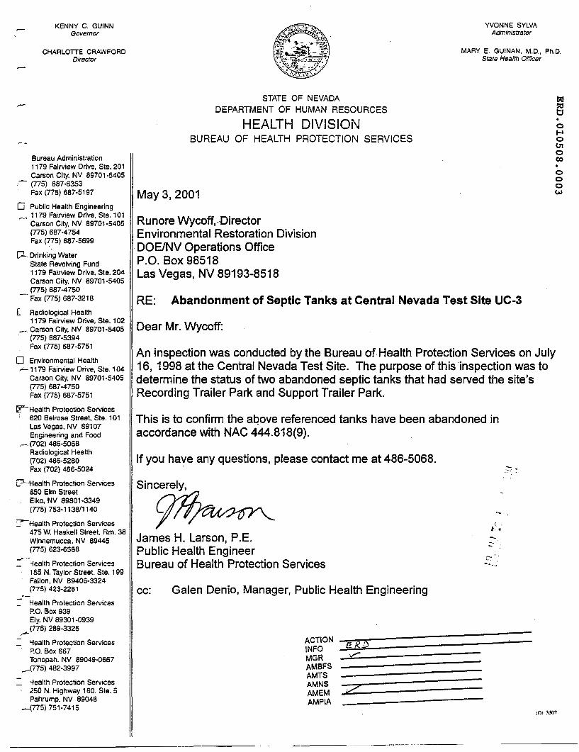
KENNY C. GUINNGovernor
CHAALOTTE CRAWFORDDirector
YVONNE SYLVAAdministrator
MARY E. GUINAN. M.D., Ph.D.State Health Officer
cc: Galen Denio, Manager, Public Health Engineering
Dear Mr. Wycoff:
RE: Abandonment of Septic Tanks at Central Nevada Test Site UC-3
o....oU1o(X)
ooow
,0' ~507
:z
ACTiONINFOMGRAMBFSAMTSAMNSAMEMAMPIA
STATE OF NEVADA
DEPARTMENT OF HUMAN RESOURCES
HEALTH DIVISIONBUREAU OF HEALTH PROTECTION SERVICES
May 3,2001
James H. Larson, P.E.Public Health EngineerBureau of Health Protection Services
Runore Wycoff,.DirectorEnvironmental Restoration DivisionDOEINV Operations OfficeP.O. Box 98518Las Vegas, NV 89193-8518
If you have any questions, please contact me at 486-5068.
Sincerely,
This is to confirm the above referenced tanks have been abandoned inaccordance with NAC 444.818(9).
An inspection was conducted by the Bureau of.Health Protection Services on July16, 1998 at the Central Nevada Test Site. The purpose of this 'inspection was todetermine the status of two abandoned septic tanks that had served the site'sRecording Trailer Park and Support Trailer Park.
Bureau Administration1179 Fairview Drive. Ste. 201Carson City. NV 89701·5405
- (775) 687·6353Fax (775) 687·5197
o Public Health Engineering.--' 1179 Fairview Drive. Ste, 101
Carson City, NV 89701-5405(775) 687·4754Fax (775) 687·5699
[:l.. Drinking WaterState Revolving Fund1179 Fairview Drive. Ste. 204Carson City. NV 89701-5405(775) 687-4750Fax (775) 687-3218
l Radiological Health1179 Fairview Drive, Ste. 102
_ Carson City. NV 89701-5405. (775) 687-5394
Fax (775) 687-5751
o Environmental Health.~ 1179 Fairview Drive. Ste. 104
Carson City, NV 89701·5405(775) 687-4750Fax (775) 687-5751
~Health Protection Services: 620 Belrose Street, Sle. 101
Las Vegas, NV 89107Engineering and Food
.-(702) 486-5068Radiological Health(702) 486-5280Fax (702) 486-5024
[?---Health Protection Services850 Elm StreetElko, NV 89801-3349(775) 753-1138/1140
:--Health Protection Services475 W. Haskell Street. Am. 38Winnemucca. NV 89445(775) 623-6588
../--;ealth Protection Services155 N. Taylor Street. Sle. 199Fallon, NV 89406-3324(775) 423-2281
Health Protection ServicesP.O. Box 939Ely. NV 89301 -0939
,......(775) 289·3325
: 'iealth Protection Services~.O.Box 667Tonopah. NV 89049-0667
.--(775) 482·3997
: -fealth Protection Services250 N. Highway 160. Sle. 5Pahrump. NV 89048
--{775) 751-7415
.-
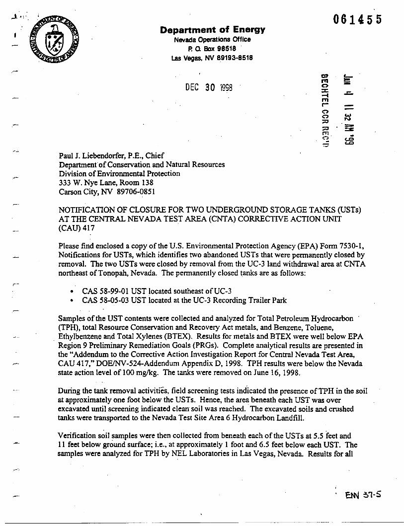
..1.: . 061455Department of Energy
Nevada Operations OfficeP. a Box 98518
Las Vegas, NV 89193·8518
CD e-m =:
DEC 30 sss 0I...... ::c-I .c.
"'r- -a -a w::0 N
::0 =-::lCrn -n c..o.. c..o.....-
Paul J. Liebendorfer, P.E., ChiefDepartment' ofConservation and Natural ResourcesDivision ofEnvironmental Protection333 W. Nye Lane, Room 138Carson City, NV 89706-q851
NOTIFICATION OF CLOSURE FOR TWO UNDERGROUND STORAGE TANKS (USTs)AT THE CENTRAL NEVADA TEST AREA (eNTA) CORRECTIVE ACTION UNIT(CAU) 417
Please find enclosed a copy of the U.S. Environmental Protection Agency (EPA) Form 7530-1,Notifications for USTs, which identifies two abandoned USTs that were permanently closed byremoval. The two USTs were closed by removal from the UC-3 land withdrawal area at CNTAnortheast ofTonopah, Nevada. The permanently closed tanks are as follows:
• CAS 58-99-01 UST located southeast ofUC-3• CAS 58-05-03 UST located at the UC-3 Recording Trailer Park
Samples of the UST contents were collected and analyzed for Total Petroleum Hydrocarbon(TPH), total Resource Conservation and Recovery Act metals, and Benzene, Toluene,
, Ethylbenzene and Total Xylenes (BTEX). Results for metals and BTEX were well below EPARegion 9 Preliminary Remediation Goals (PRGs). Complete analytical results are presented inthe "Addendum to the Corrective Action Investigation Report for Central Nevada Test Area,
r-- CAU 417," DOEINV-524-Addendum Appendix D, 1998. TPH results were below the Nevadastate action level of 100 mg/kg. The tanks were removed on June 16, 1998.
During the tank removal activities, field screening tests indicated the presence ofTPH in the soilat approximately one foot below the USTs. Hence, the area beneath each UST was overexcavated until screening indicated clean soil was reached. The excavated soils and crushedtanks were transported to the Nevada Test Site Area 6 Hydrocarbon Landfill.
Verification soil samples were then collected from beneath each of the USTs at 5.5 feet and11 feet below ground surface; i.e., at approximately 1 foot and 6.5 feet below each UST. Thesamples were analyzed for TPH by NEL Laboratories in Las Vegas, Nevada. Results for all
.-:.:.
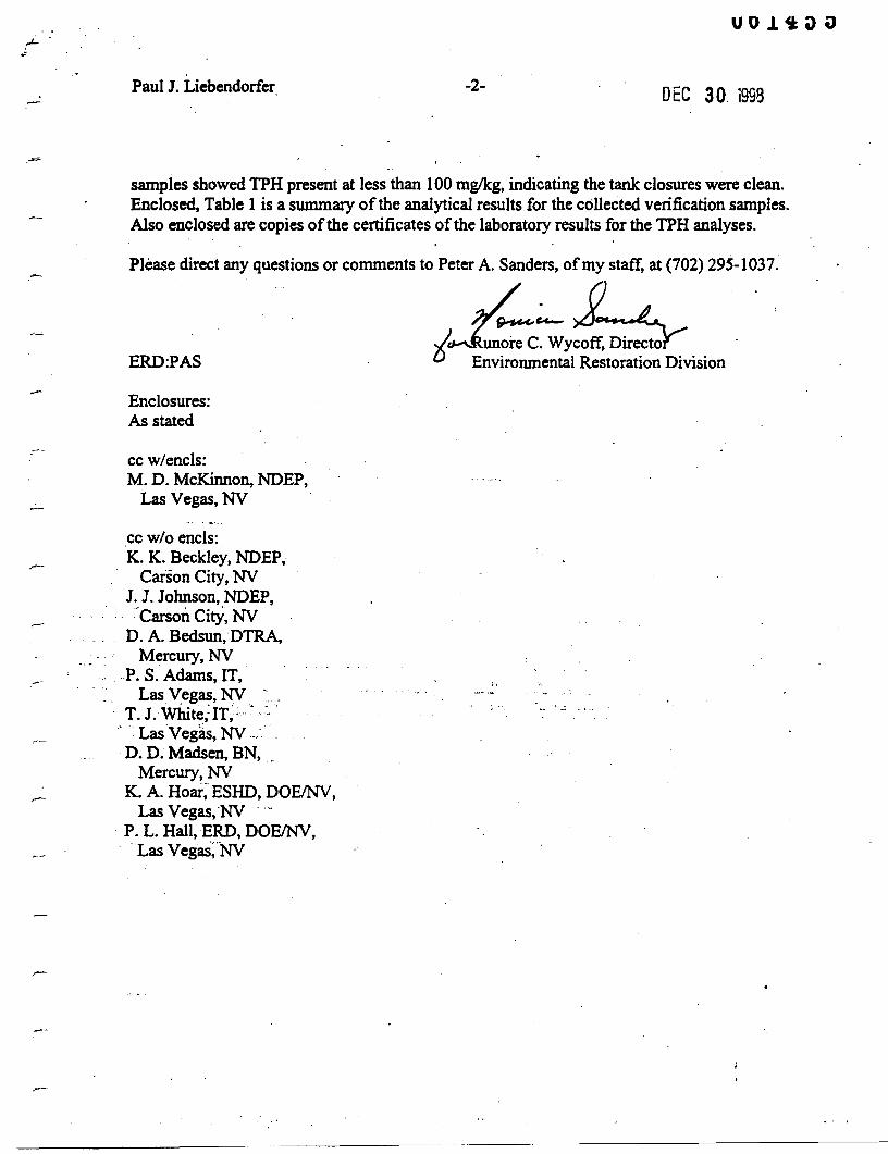
Paul J. Liebendorfer -2- DEC 30. 1998
samples showedTPH present at less than 100 mg/kg, indicatingthe tank closureswere clean.Enclosed, Table I is a summary ofthe analytical results for the collected verificationsamples.Also enclosedare copies ofthe certificates ofthe laboratory results for the TPH analyses.
Please direct any questionsor comments to Peter A. Sanders,ofmy staff, at (702) 295-1037.
.JJfj~yb .ERD:PAS l;. Environmental RestorationDivision
Enclosures:As stated
cc w/encls:M. D. McKinnon,NDEP,
Las Vegas,NY
cc wlo encls:K. K. Beckley, NDEP,
Carson City,NYJ.J. Johnson, NDEP,
.-CarsonCitY, NYD. A. Bedsun,DTRA,
Mercury,NY.P. S. Adams, IT,
Las Vegas, NY' ':.. ,T. J.w1ute;IT;:· ~'.~.'
" LasVegas, NY.: .D. D. Madsen,BN, .
Mercury, NYK. A. Hoar: ESHD, DOEINV,
Las Vegas,'NY .... -. P. L. Hall,ERO, DOEINV,
Las Vegas:'!'lV
PETER G. ~IORROS. Directo»
AI.I.EX BIAGGI. Administrator
17i516874670
TOO 687-4678
AdministrationWaterPollutionControlFacsimil, 65,·5856
STATE OF NEVADAKE:-<~I' C, GUNS
GocemorWaste ~lanagement
Corrective ..lu:tionsFederal Facilities
AirQualityWater Quality Planning
Facsimil, 687-6396
:'lining Regulation and ReclamationFacsimil, ~·5259 DEPARnlENT OF CONSER\:~TION AND NATL'RU RESOVRCES
DIVISION OF ENViRONMENTAL PROTECTION333 W. Nye Lane, Room 138
.-- Carson City, Nevada 89i06
May 29, 2001
.--- RunoreC. Wycoff, DirectorEnvironmental Restoration DivisionNational NuclearSecurityAdministrationNevadaOperations OfficeP.O. Box 98593-8518Las Vegas, Nevada89193-8518
ACTION -_vr::::-"'?J'?J:;:;:!:'O;::;;::;------INFOMGRAMBFSAMTSAMNSAMEMAMPIA
RE: ClosureDocumentation Received for Underground StorageTanks; CAU 417 - CentralNevadaTest Area
DearMs. Wycoff:
The Nevada Divisionof Environmental Protection (NDEP) has received the UndergroundStorageTank Notification Form (USEPA Form 7530) for two underground storage tanks (USTs)that were discovered abandoned at the Central NevadaTest Area (CAU 417) during fieldoperations in 1998. Alongwith a letterdatedDecember30, 1998 which accompanied the 7530Form, the following information was provided:
• Two tankswere permanently closedon July 16, 1998;• The tanks are numbered CAS 58-99-01 and CAS 58-05-03;• The tanks were welded 55 gallonsteel drums; were used to contain diesel; had
approximate volumes of220 and 165 gallons; and were last used in 1968.
During tank removal, field screening tests indicated the presenceofTPH in soil below the USTs.Over-excavation was performed below eachtank siteuntil screening indicated clean soil hadbeen reached. Removedsoil and the crushed USTswere transported to the Nevada Test SiteArea 6 Hydrocarbon Landfill. Confirmatory soil samples werecollected as part of a siteassessment as requiredby federal regulation 40 CFRPart 280.72 and analyzedfor TotalPetroleumHydrocarbons (TPH). Results for all samples showedTPH concentrations at less than
.-
,--
-
Runore C. WycoffPage 2May 29,2001
the action level of 100 mg/kg, The highest reported samplingresult was 81 mg/kg TPH at thesouth end of CAS 58-05-03.
Upon review of the data presented, the NDEPconcurs that the tank removals and the subsequentremoval ofcontaminated soils were done satisfactorily and conform to StateofNevadaregulations. Confirmatory soil samplingresults indicate that remaining TPH is below theStateaction level. The NDEP will not requireremedial action involvingthese two tanks. No remedialaction is based upon the information and data provided to date (7530Form and December30,1998 DOE letter). This actionis subject to the qualifications of the data and informationpresented. If future conditions warrant, NDEP may request furtherinformation, data,investigation and/or remediation.
Additionally, steps to formally close CAS 58-99-01 and CAS 58-05-03 must be completed underthe provisionsof the FFACO. These two CASs, along with the other CNTA surface sites,mustbe included in the ClosureReport for CAU417. !fyou have any questions regarding tankclosure issues,please contactSigurd Jaunarajs of my staff at (775) 687-4670, extension3030.
Sincerely, '
-~ChiefBureau of Federal Facilities
PJL/SRJ/js
cc: Karen Beckley, NDEP/CCMatt DeBurle, NDEP/CCPatti Hall, ERD, NNSAINVMike McKinnon, NDEP/LVMonica Sanchez, ERO, NNSAINVPete Sanders, ERD, NNSAINV

This page intentionally left blank
APPENDIXF
USE RESTRICTION DOCUMENTATION
THIS PAGE INTENTIONALLY LEFT BLANK
I
till
•'''''....•••
••••••••......
••
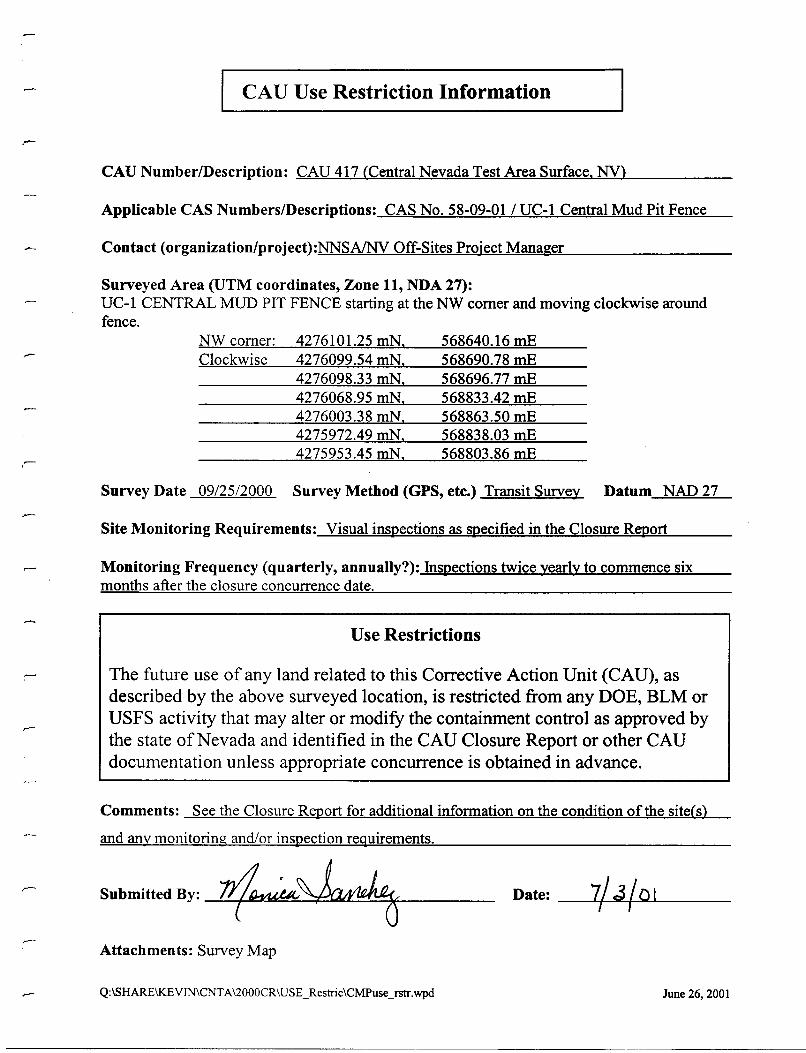
CAU Use Restriction Information
CAU Number/Description: CAU 417 (Central Nevada Test Area Surface. NY)
Applicable CAS Numbers/Descriptions: CAS No. 58-09-01/ UC-l Central Mud Pit Fence
Contact (organization/project):NNSA/NV Off-Sites Project Manager
Surveyed Area (UTM coordinates, Zone 11, NDA 27):UC-l CENTRAL MUD PIT FENCE starting at the NW comer and moving clockwise aroundfence.
- NW comer:Clockwise
4276101.25 mN.4276099.54 mN.4276098.33 mN.4276068.95 mN.4276003.38 mN.4275972.49 mN.4275953.45 mN.
568640.16 mE568690.78 mE568696.77 mE568833.42 mE568863.50 mE568838.03 mE568803.86 mE
Survey Date 09/2512000 Survey Method (GPS, ete.) Transit Survey Datum NAD 27
Site Monitoring Requirements: Visual inspections as specified in the Closure Rm>ort
Monitoring Frequency (quarterly, annually?): Inspections twice yearly to commence sixmonths after the closure concurrence date.
Use Restrictions
The future use of any land related to this Corrective Action Unit (CAU), asdescribed by the above surveyed location, is restricted from any DOE, BLM orUSFS activity that may alter or modify the containment control as approved bythe state ofNevada and identified in the CAD Closure Report or other CADdocumentation unless appropriate concurrence is obtained in advance.
Comments: See the Closure Report for additional information on the condition of the site(s)
and any monitoring and/or inspection requirements.
Submitted By: 1~~Attachments: Survey Map
Q:\sHARE\KEVIN\CNTA\2000CR\USE_Restric\CMPuseJstr.wpd
Date: _----'+--""'+ L...- _
June 26, 2001
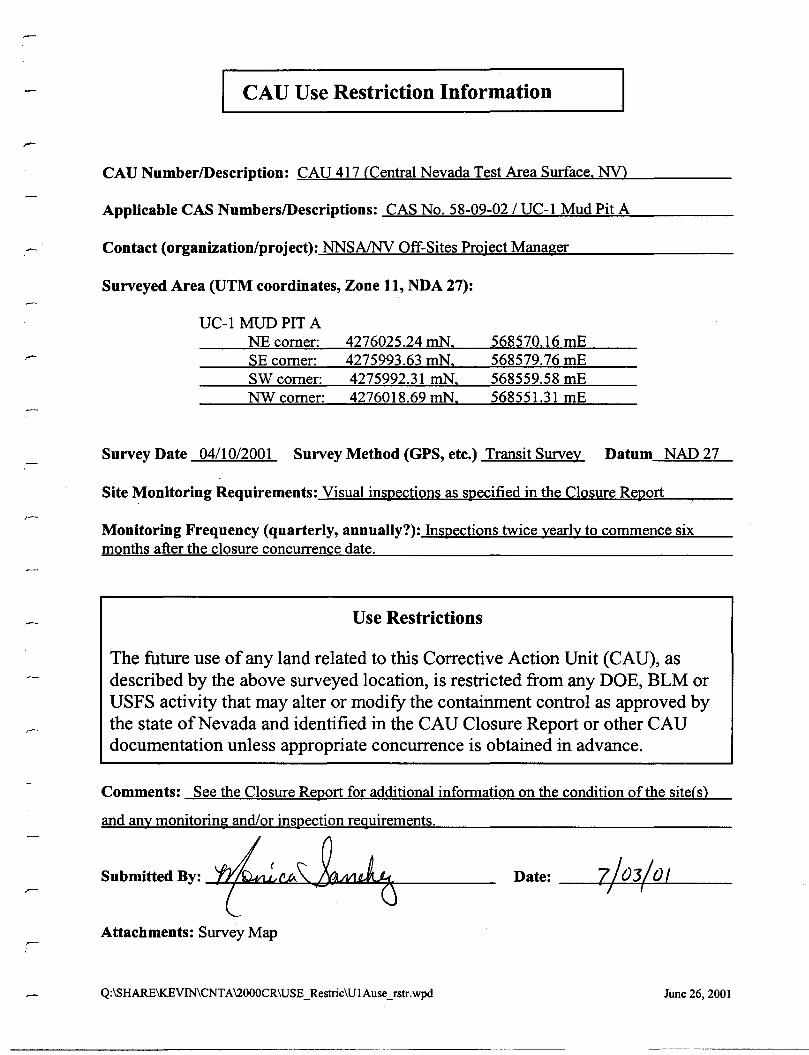
I CAU Use Restriction Information
CAU NumberlDescription: CAU 417 CCentral Nevada Test Area Surface. NY>
Applicable CAS NumberslDescriptions: CAS No. 58-09-02 / UC-1 Mud Pit A
Contact (organization/project): NNSAINV Off-Sites Project Manager
Surveyed Area (UTM coordinates, Zone 11, NDA 27):
UC-1 MUD PIT ANEcomer:SE comer:
4276025.24 mN.4275993.63 mN.
568570.16 mE568579.76 mE
SWcomer:NWcomer:
4275992.31 mN.4276018.69 mN.
568559.58 mE568551.31 mE
Survey Date 04/10/2001 Survey Method (GPS, ete.) Transit Survey Datum NAD 27
Site Monitoring Requirements: Visual inspections as specified in the Closure Report
Monitoring Frequency (quarterly, annually?): Inspections twice yearly to commence sixmonths after the closure concurrence date.
Use Restrictions
The future use of any land related to this Corrective Action Unit (CAU), asdescribed by the above surveyed location, is restricted from any DOE, BLM orUSFS activity that may alter or modify the containment control as approved bythe state ofNevada and identified in the CAU Closure Report or other CAUdocumentation unless appropriate concurrence is obtained in advance.
Comments: See the Closure Report for additional information on the condition of the siteCs)
and any monitoring and/or inspection requirements.
7/03/ 0 1r,Date: __-I-+....;;;...::~"'-'- _Submltted By: f~~~Attachments: Survey Map
Q:\SHARE\KEVIN\CNTA\2000CR\USE_Restric\UIAuse_rstr.wpd June 26, 2001
~-----------~._------

-CAU Use Restriction Information
CAU Number/Description: CAD 417 (Central Nevada Test Area Surface. NY)
Applicable CAS Numbers/Descriptions: CAS No. 58-09-05 / DC-1 Mud Pit E
Contact (organization/project): NNSAINV Off-Sites Project Manager
Surveyed Area (UTM coordinates, Zone 11, NDA 27):
UC-1 MUD PIT ENEcomer:SEcomer:SWcomer:NWcomer:
4276310.02 mN.4276274.84 mN.4276293.13 roN.4276316.81 mN.
568438.16 mE568433.69 mE568394.17 mE568403.87 mE
Survey Date 04/10/2001 Survey Method (GPS, etc.) Transit Survey Datum NAD 27
Site Monitoring Requirements: Visual inspections as specified in the Closure R~ort
Monitoring Frequency (quarterly, annually?): Inspections twice yearly to commence sixmonths after the closure concurrence date.
Use Restrictions
The future use of any land related to this Corrective Action Unit (CAU), asdescribed by the above surveyed location, is restricted from any DOE, BLM orUSFS activity that may alter or modify the containment control as approved bythe state ofNevada and identified in the CAU Closure Report or other CAUdocumentation unless appropriate concurrence is obtained in advance.
Comments: See the Closure R~ort for additional information on the condition of the site(s)
and any monitoring and/or inspection requirements.
Submitted By: --L.L.-/-~~~u.",,~,.K.Ll"""4-"""'_----
Attachments: Survey Map
Q:\sHARE\KEVIN\CNTA\2000CR\USE_Restric\UIEuseJstr.wpd
'7 ) O~/IJIr '
June26, 200I

CAU Use Restriction Information
CAD Number/Description: CAU 417 (Central Nevada Test Area Surface. NV)
Applicable CAS Numbers/Descriptions: CAS No. 58-09-06 1UC-3 Mud Pit E
r:: Contact (organization/project): NNSAINV Off-Sites Project Manager
Surveyed Area (UTM coordinates, Zone 11, NDA 27):
UC-3 MUD PIT ENEcomer:SE comer:SWcomer:NWcomer:
4271893.96 mN.4271869.14 mN.4271875.25 mN.4271906.84 mN.
568038.66 mE568029.52 mE567990.52 mE567991.36 mE
.-
Survey Date 04/10/2001 Survey Method (GPS, ete.) Transit Survey Datum NAD 27
Site Monitoring Requirements: Visual inspections as specified in the Closure Report
Monitoring Frequency (quarterly, annually?): Inspections twice yearly to commence sixmonths after the closure concurrence date.
Use Restrictions
The future use of any land related to this Corrective Action Unit (CAD), asdescribed by the above surveyed location, is restricted from any DOE, BLM orDSFS activity that may alter or modify the containment control as approved bythe state ofNevada and identified in the CAD Closure Report or other CADdocumentation unless appropriate concurrence is obtained in advance.
Comments: See the Closure Report for additional infonnation on the condition ofthe site(s)
and any monitoring and/or inspection requirements.
Submitted By: -I-:....j...~4.L.J~~"""l.1!a~:J""I,o~ _
Attachments: S
Q:\SHARE\KEVIN\CNTA\2000CR\USE_Restric\U3Euse_fstr.wpd
Date: -Lf-........~L+-----
June 26, 2001
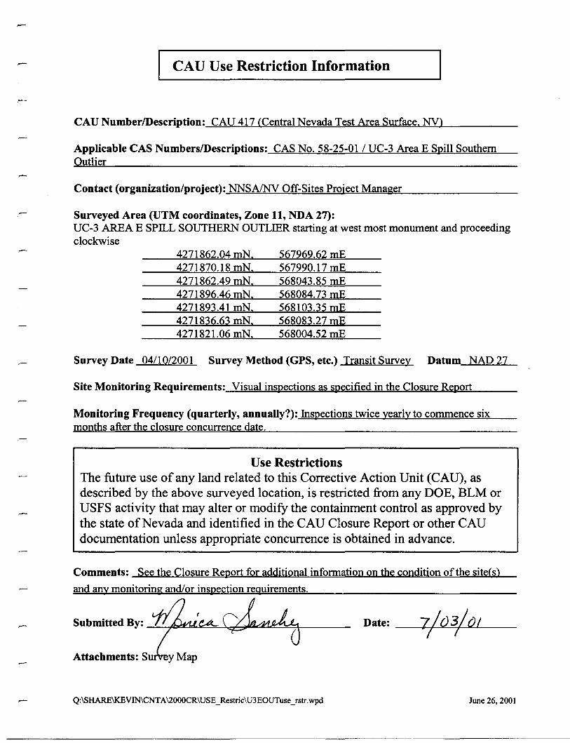
I CAU Use Restriction Information
CAU NumberlDescription: CAU 417 (Central Nevada Test Area Surface. NV)
Applicable CAS NumberslDescriptions: CAS No. 58-25-01 / UC-3 Area E Spill SouthernOutlier
Contact (organization/project): NNSAINV Off-Sites Project Manager
Surveyed Area (UTM coordinates, Zone 11, NDA 27):UC-3 AREA E SPilL SOUTHERN OUTLIER starting at west most monument and proceedingclockwise
4271862.04 mN.4271870.18 mN.4271862.49 mN.4271896.46 mN.4271893.41 mN.4271836.63 mN.4271821.06 mN.
567969.62 mE567990.17 mE568043.85 mE568084.73 mE568103.35 mE568083.27 mE568004.52 mE
Survey Date 04/10/2001 Survey Method (GPS, etc.) Transit Survey Datum NAD 27
Site Monitoring Requirements: Visual inspections as specified in the Closure Report
Monitoring Frequency (quarterly, annually?): Inspections twice yearly to commence sixmonths after the closure concurrence date.
Use RestrictionsThe future use of any land related to this Corrective Action Unit (CAU), asdescribed by the above surveyed location, is restricted from any DOE, BLM orUSFS activity that may alter or modify the containment control as approved bythe state of Nevada and identified in the CAU Closure Report or other CAUdocumentation unless appropriate concurrence is obtained in advance.
Comments: See the Closure Report for additional information on the condition of the site(s)
and any monitoring and/or inspection requirements.
Submitted By: -!...:....j.~~~~d-,;;Jt:lt.::z~~;\----
Attachments: S
Q:\SHARE\KEVIN\CNTA\2000CR\USE_Restric\U3EOUTuseJstr.wpd
Date: --I-f-~=+"""""J----
June 26, 2001
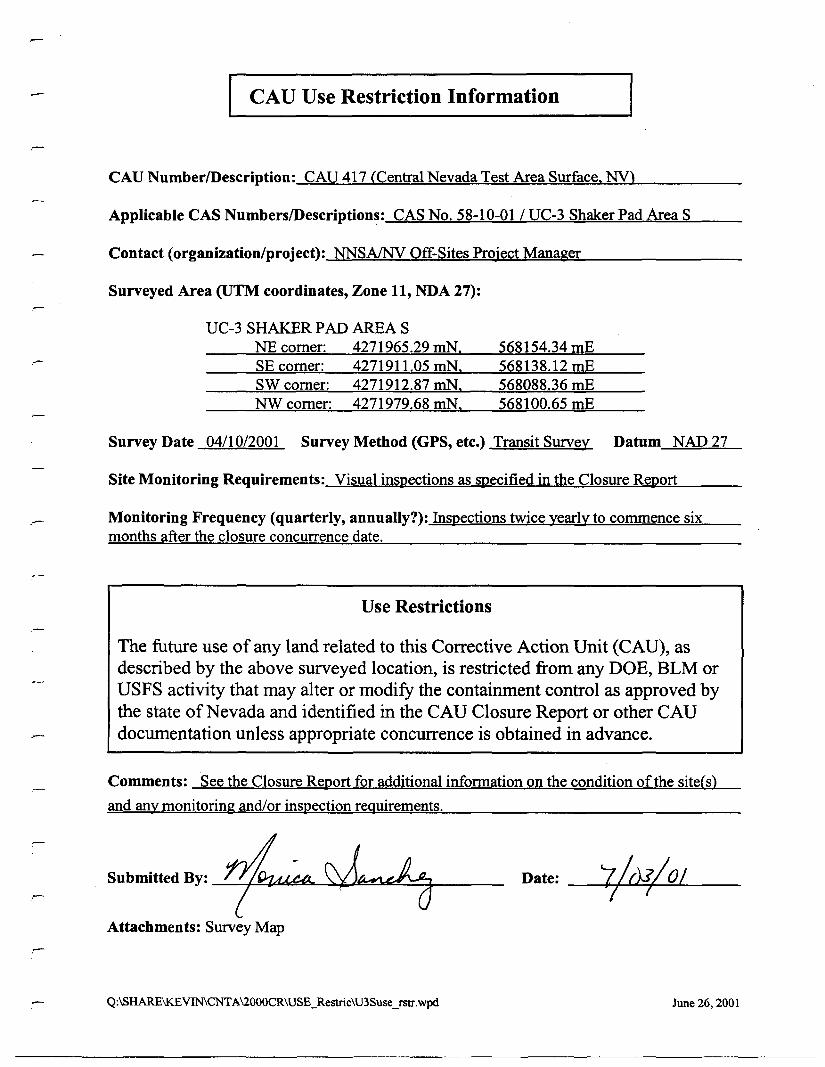
I CAU Use Restriction Information
CAD NumberlDescription: CAU 417 (Central Nevada Test Area Surface. NV)
Applicable CAS NumberslDescriptions: CAS No. 58-10-01 / UC-3 Shaker Pad Area S
Contact (organization/project): NNSAINV Off-Sites Project Manager
Surveyed Area (UTM coordinates, Zone 11, NDA 27):
UC-3 SHAKERPADAREASNE comer:SE comer:SW comer:NWcomer:
4271965.29 rnN.4271911.05 rnN.4271912.87 rnN.4271979.68 mN.
568154.34 mE568138.12 mE568088.36 mE568100.65 mE
Survey Date 04/10/2001 Survey Method (GPS, etc.) Transit Survey Datum NAD 27
Site Monitoring Requirements: Visual inspections as specified in the Closure Report
Monitoring Frequency (quarterly, annually?): Inspections twice yearly to commence sixmonths after the closure concurrence date.
Use Restrictions
The future use of any land related to this Corrective Action Unit (CAU), asdescribed by the above surveyed location, is restricted from any DOE, BLM orDSFS activity that may alter or modify the containment control as approved bythe state of Nevada and identified in the CAD Closure Report or other CADdocumentation unless appropriate concurrence is obtained in advance.
Comments: See the Closure Report for additional infonnation on the condition ofthe site(s)
and any monitoring and/or inspection reguirements.
Submitted By: -=-...:.....,~{44C::1l:~~~~~-==+---_
Attachments: Survey Map
Q:\SHARE\KEVIN\CNTA\2000CR\USE_Restric\U3Suse_rstr.wpd
Date: ---,Jt-+-~~..=.L_--
June 26, 2001
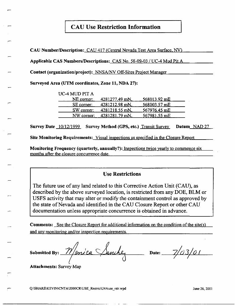
I CAU Use Restriction Information
CAU NumberlDescription: CAU 417 (Central Nevada Test Area Surface. NY)
Applicable CAS NumberslDescriptions: CAS No. 58-09-03 / UC-4 Mud Pit A
Contact (organization/project): NNSAINV Off-Sites Project Manager
Surveyed Area (UTM coordinates, Zone 11, NDA 27):
UC-4 MUD PIT ANEcomer:SE comer:SW comer:NWcomer:
4281277.49 mN.4281212.98 mN.4281218.55 mN.4281281.79 mN.
568013.92 mE568003.57 mE567976.45 mE567981.55 mE
Survey Date 10/12/1999 Survey Method (GPS, etc.) Transit Survey Datum NAD 27
Site Monitoring Requirements: Visual inspections as specified in the Closure Report
Monitoring Frequency (quarterly, annually?): Inspections twice yearly to commence sixmonths after the closure concurrence date.
Use Restrictions
The future use ofany land related to this Corrective Action Unit (CAU),asdescribed by the above surveyed location, is restricted from any DOE, BLM orUSFS activity that may alter or modify the containment control as approved bythe state ofNevada and identified in the CAU Closure Report or other CAUdocumentation unless appropriate concurrence is obtained in advance.
Comments: See the Closure Report for additional infonnation on the condition of the site(s)
and any monitoring and/or inspection reguirements.
Submitted By: ~'I!A~Attachments: Survey Map
Q:\SHARE\KEVIN\CNTA\2000CR\USE_Restric\U4Ause_Tstr.wpd
Date: --4T....L.oo:....I.oC;~~--
June 26,2001
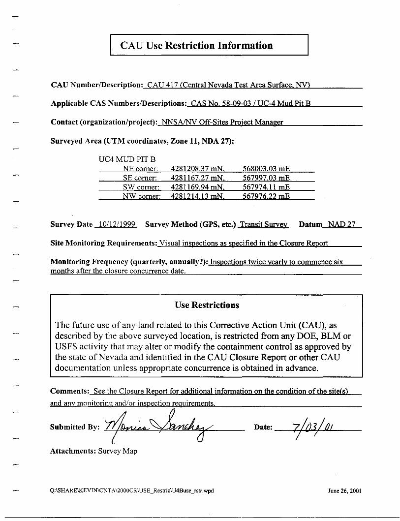
CAU Use Restriction Information
CAU Number/Description: CAU 417 CCentral Nevada Test Area Surface. NY)
Applicable CAS Numbers/Descriptions: CAS No. 58-09-03 / UC-4 Mud Pit B
Contact (organization/project): NNSAINV Off-Sites Project Manager
Surveyed Area (UTM coordinates, Zone 11, NDA 27):
UC4MUDPITBNE comer:SE comer:SW comer:NWcomer:
4281208.37 mN.4281167.27 mN.4281169.94 mN.4281214.13 mN.
568003.03 mE567997.03 mE567974.11 mE567976.22 mE
Survey Date 10/12/1999 Survey Method (GPS, etc.) Transit Survey Datum NAD 27
Site Monitoring Requirements: Visual inspections as specified in the Closure Report
Monitoring Frequency (quarterly, annually?): Inspections twice yearly to commence sixmonths after the closure concurrence date.
Use Restrictions
The future use of any land related to this Corrective Action Unit (CAU), asdescribed by the above surveyed location, is restricted from any DOE, BLM orUSFS activity that may alter or modify the containment control as approved bythe state of Nevada and identified in the CAU Closure Report or other CAUdocumentation unless appropriate concurrence is obtained in advance.
Comments: See the Closure Report for additional information on the condition of the siteCs)
and any monitoring and/or inspection requirements.
Submitted By: ~;.,...~/ Date: #'Attachments: Survey Map
Q:\SHARE\KEVIN\CNTA'l000CR\USE_Restric\U4BuseJstr.wpd June 26, 200I
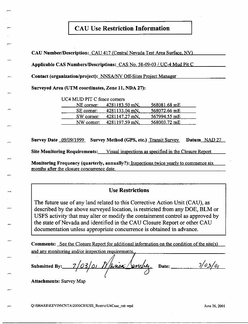
I CAU Use Restriction Information
CAU Number/Description: CAD 417 (Central Nevada Test Area Surface. NY)
Applicable CAS Numbers/Descriptions: CAS No. 58-09-03 / UC-4 Mud Pit C
Contact (organization/project): NNSAINV Off-Sites Project Manager
Surveyed Area (UTM coordinates, Zone 11, NDA 27):
UC4 MUD PIT C fence comersNEcomer:SE comer:SWcomer:NWcomer:
4281183.50 roN.4281133.04 mN.4281147.27 mN.4281197.59 roN.
568081.68 mE568072.66 mE567994.55 mE568003.72 mE
Survey Date 09/09/1999 Survey Method (GPS, ete.) Transit Survey Datum NAD 27
Visual inspections as specified in the Closure Re,portSite Monitoring Requirements:_---'-==-:===........=-:o~=.:::=..........,=..=.:o;=::..::....=="'__ __
Monitoring Frequency (quarterly, annually?): Inspections twice yearly to commence sixmonths after the closure concurrence date.
Use Restrictions
The future use of any land related to this Corrective Action Unit (CAU), asdescribed by the above surveyed location, is restricted from any DOE, BLM orUSFS activity that may alter or modify the containment control as approved bythe state ofNevada and identified in the CAU Closure Report or other CAUdocumentation unless appropriate concurrence is obtained in advance.
Comments: See the Closure Report for additional information on the condition of the site(s)
and an monitorin
Date: 1-.-=+--:;...1_
Attachments: Survey Map
Q:\SHARE\KEVIN\CNTA\2000CR\USE_Restric\U4Cuse_fstr.wpd June 26, 2001

I CAU Use Restriction Information
CAD NumberlDescription: CAU 417 (Central Nevada Test Area Surface. NV)
Applicable CAS NumberslDescriptions: CAS No. 58-09-03 / UC-4 Mud Pit D
Contact (organization/project): NNSAINV Off-Sites Project Manager
Surveyed Area (UTM coordinates, Zone 11, NDA 27):
UC4MUD PITDNEcomer:SE comer:SWcomer:NWcomer:
4281161.15 mN.4281126.83 mN.4281139.32 mN.4281165.56 mN.
568134.18 mE568119.03 mE568075.08 mE568081.63 mE
Survey Date 10/12/1999 Survey Method (GPS, etc.) Transit Survey Datum NAD 27
Site Monitoring Requirements: Visual inspections as specified in the Closure Report
Monitoring Frequency (quarterly, annually?): Inspections twice yearly to commence sixmonths after the closure concurrence date.
Use Restrictions
The future use of any land related to this Corrective Action Unit (CAU), asdescribed by the above surveyed location, is restricted from any DOE, BLM orUSFS activity that may alter or modify the containment control as approved bythe state of Nevada and identified in the CAU Closure Report or other CAUdocumentation unless appropriate concurrence is obtained in advance.
Comments: See the Closure Report for additional information on the condition of the site(s)
Submitted By: ...LL/,P2~:::«''''''''::::;±~1:1::J~:::::!!:+-,...-----
Attachments: Survey Map
Q:\SHARE\KEVIN\CNTA\2000CR\USE_Restric\U4DuseJstr.wpd
Date: ----Jl'-f-....I.Ll--4-~...L..-_-
June 26,2001
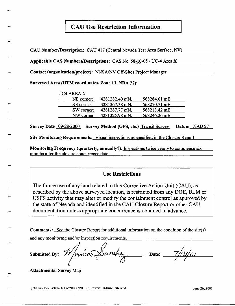
I CAU Use Restriction Information
CAU Number/Description: CAU 417 (Central Nevada Test Area Surface. NY)
Applicable CAS Numbers/Descriptions: CAS No. 58-10-05/ UC-4 Area X
Contact (organization/project): NNSA/NV Off-Sites Project Manager
Surveyed Area (UTM coordinates, Zone 11, NDA 27):
UC4AREAXNE comer:SE comer:SW comer:NWcomer:
4281282.40 mN.4281267.38 mN.4281287.77 mN.4281325.98 mN.
568284.01 mE568270.71 mE568213.42 mE568246.26 mE
Survey Date 09/28/2000 Survey Method (GPS, etc.) Transit Survey Datum NAD 27
Site Monitoring Requirements: Visual inspections as specified in the Closure Re.port
Monitoring Frequency (quarterly, annually?): Inspections twice yearly to commence sixmonths after the closure concurrence date.
Use Restrictions
The future use of any land related to this Corrective Action Unit (CAU), asdescribed by the above surveyed location, is restricted from any DOE, BLM orUSFS activity that may alter or modify the containment control as approved bythe state of Nevada and identified in the CAU Closure Report or other CAUdocumentation unless appropriate concurrence is obtained in advance.
Comments: See the Closure Report for additional information on the condition of the site(s)
and any monitoring and/or inspection requirements.
Submitted By: -.L'..L.#.~~~~'o2!:.~!:!:£~~ _
Attachments: Survey Map
Q:\SHARE\KEVIN\CNTA\2000CR\USE_Restric\U4XuseJstr.wpd
Date: --"'<'+~=r-''''''''---
June 26, 2001
United States Department of the Interior
Bureau of Land ManagementTonopah Field Station
1553 S. Main StreetP.O. Box 911
Tonopah,Nevada 89049(775)482-7800 Fax (775)482-7810
In Reply Refer to:NV065-1640
65.01
MAY 2 I 2001Runore C. Wycoff, DirectorEnvironmental Restoration Div.Departmentof EnergyNevada Operations OfficeP.O. Box 98518Las Vegas, NV 89193-8518
RE: Environmental Restoration Activities for the U.S. Department of Energy's(DOE) Central Nevada Test Area, Hot Creek Valley, Nevada
The Bureau of land Management, Tonopah Field Station, is in receipt of DOE's document"CorrectiveAction Plan for Corrective Action Unit 417: Central Nevada Test Area Surface,Nevada." The document, which describes your planned environmental restoration activities onDOE land withdrawals in Hot Creek Valley, was received on or about April 16, 2000.
We look forward to receiving a copy of the completed Closure Report, which we understand willdocument the completed restoration activities at the DOE sites and offer information on land userestrictions on the withdrawn lands. Once the Closure Plan has been approved: we willincorporate the document into the official land withdrawal file.
If you have any questions, please contact Bill Fisher at (775) 482-7830.
.ooot-J
7
Sincerely.. , rI/.
/JY £'Z;971"~,~\V. Craig ~{acKinnonAssistant Field Manager, Tonopah
t
ACTION -=-:~-----------INFOMGRAMBFSAMTSAMNSAMEMAMPIA
APPENDIXG
SAMPLING, INSPECTION, TESTING, ANDACCEPTANCE (SITA) APPROVAL
MATRIx/CHECKLIST
-----------------------------
THISPAGE INTENTIONALLY LEFTBLANK.
J.J
•
••
••
••
•....•••
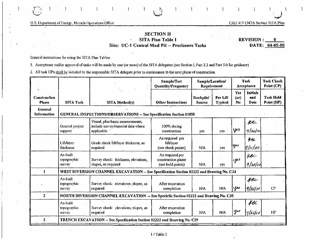
r"'~·\
v-... :,
• ,'I-.-1\.... ','
f4.ii ·l........,f
CI\.U 417 CNTI\. Surface SITI\. PlanIII
SECTION IISITA Plan Table I
Site: UC-t Central Mud Pit -- Preclosure TasksREVISION: 0
DATE: 04-05-00
General instructions for using thc·SITAPlan Tables:
I. Acceptance and/or approval or tasks will be made by one (or more) of the SITA delegates (see Section I, Pm12.2 and Part 5.0 for guidance)
2. 1\.11 task IIPs shall be initialedby the responsible SITI\. delegate prior to continuance to the next phase or construction.
Sampleffcst Sample/Location/ Task Task CheckQuantit"/FrclIUenc," Requirement Acceptance Point (CP)
.,
Yes InitialsCondruction Stockplle/ Per Lin (or) and Tasl< Hold
Phase SITA Tasle SITA Method(s) Other Instructions Source Typlcal No Date Point (HP)
GeneralInformation GENERAL INSPECTIONS/OBSERVATIONS - See Specification Section 01050
Visual, plus basic measurements, ./UJeGeneral project include survev/material data where 100% during
\~ ...,/1.6{0,support applicable . construction yes yes
As required per .~.Lift/laver Grade check lift/layerthickness,as liftl1ayer
~thickness required (see check points) N/A yes 7/1/100As-built As required per j{8c>topographic Survey check: thickness,elevations, construction phase LfA
tfItt/v"survev slopes, as required (see hold points) N/A ves..I WEST DIVERSION CHANNEL EXCAVATION -'-See Specification Section 02222 and Drawing No. C34
As-built .J!$v. topographic Surveycheck: elevations, slopes, as After excavation
SUITCY required completion N/A N/A t.J-U '11:zt/.70 CP
2 NORTH DIVERSION CHANNEL EXCAVATION -- See Specicfic Section 02222 and Drawing No. C35
As-built #c,topographic SlIITCY check: elevations,-slopes, as After excavationsurvev required completion N/A" N/A ~ 1/t t/(/ iJ l-lP
3 TRENCH EXCAVATION -- See Specification Section 02222 and Drawing No. C29
I /Table I
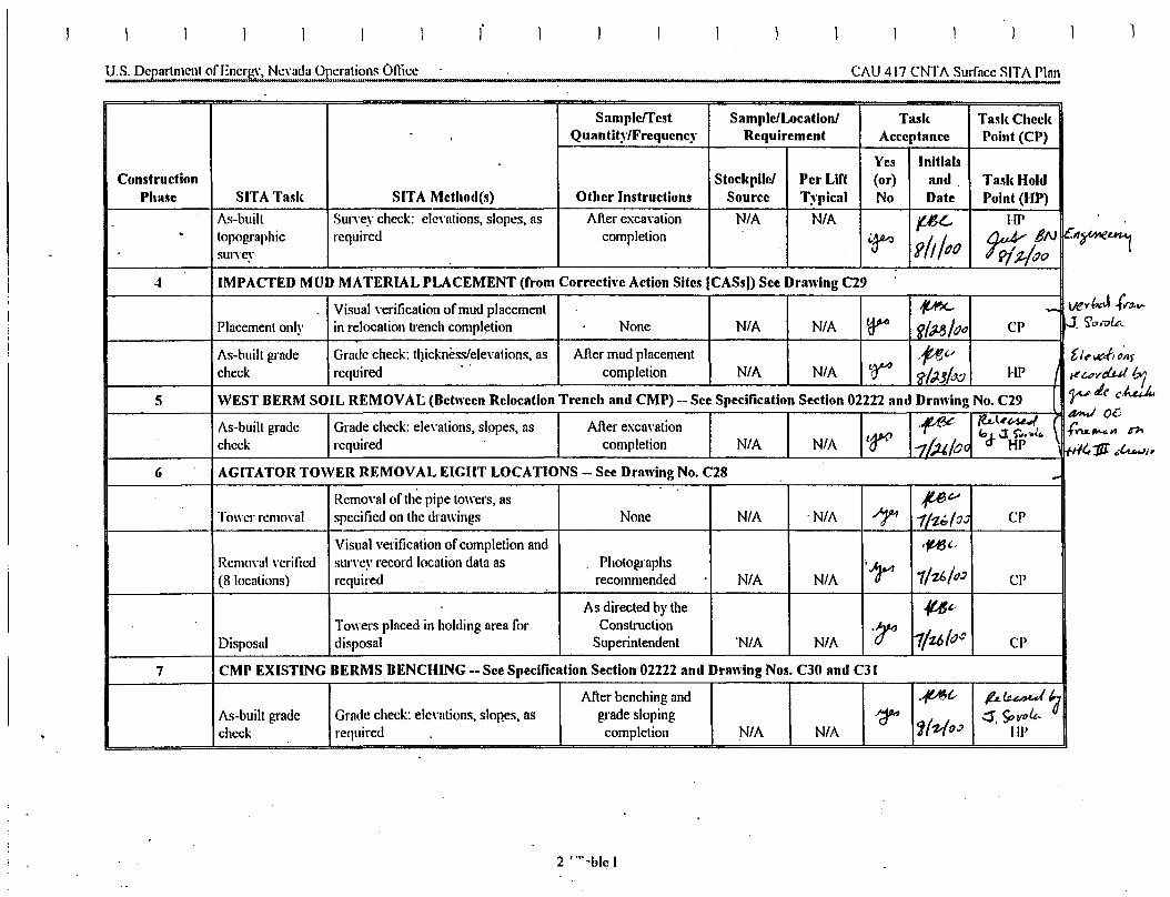
I 1
CAU 417 CNTA Surface SITA Plan
Ve'rt..J .(f''''Y'<10,7)&,
[,/~vd(J~}
/Luvd.u! '1~"(C~
a-.I oerwu.,..... '" "'"~11I ...f.u..Ji r
Sample/Test Sample/Locationl Task Tasl< CheckQuantit)'/Frequency Requirement Acceptance Point (CP)
Yes InitialsConstruction StocI<pilel Per Lift (or) and Tasl<Hold
Phase SITA Tasl< SITA Method(s) Other Instructions Source Typical No Date Point (HP)
As-buill Survey check: elevations, slopes, as After excavation N/A N/A jtU-, HI'. topographic required completion i~ Slil/()() f:j;BN e:sut....ev ~~/t70
.. IMPACTED MUD MATERIAL PLACEMENT (from Corrective Action Sites (CASsJ) See Drawing C29
Visual verification ofmud placement ~ --.
Placement only in relocation trench completion None N/A N/A ~ fjIJ..Ij/ tJ" CP ..J
As-built grade Grade check: thickness/elevations, as After mud placement ~", '-'
check required..
completion N/A N/A ~ <;r!J.J!()O HI'
5 WEST BERM SOIL REMOVAI:. (Between Relocation Trench and CMP) -- See Specification Section 02222 and Drawing No. C29
As-buill grade Grade check: elevations, slopes, as After excavation ,~ ~l#~
taw (,d- J: s:,...4,check required completion N/A N/A 1"'1/,).(,/OG HI' fI
6 AGITATOR TOWER REMOVAL EIGHT LOCATIONS - See Drawing No. C28 ..Removal of the pipe towers, as Jle~
Tower removal specified on the drawings None N/A 'N/A T 1/'Z6lo.JCP
Visual verification of completion and .~,.
Removal verified survey record location data as Photographs '1r' 1/u!tJJ(8 locations) required recommended N/A N/A CP
As directed bythe '(ut..Towers placed in holding area for Construction .~ 11t61()~Disposal disposal Superintendent 'N/A N/A CP
7 CMP EXISTING BERMS BENCHING - See Specification Section 02222 and Drawing Nos. C30 and C31
After benching and .pl- ILluALJ ";As-buill grade Grade check: elevations, slopes, as grade sloping .~
1('Z10 ,;l.:s. SO vult..
check required completion N/A N/A lIP
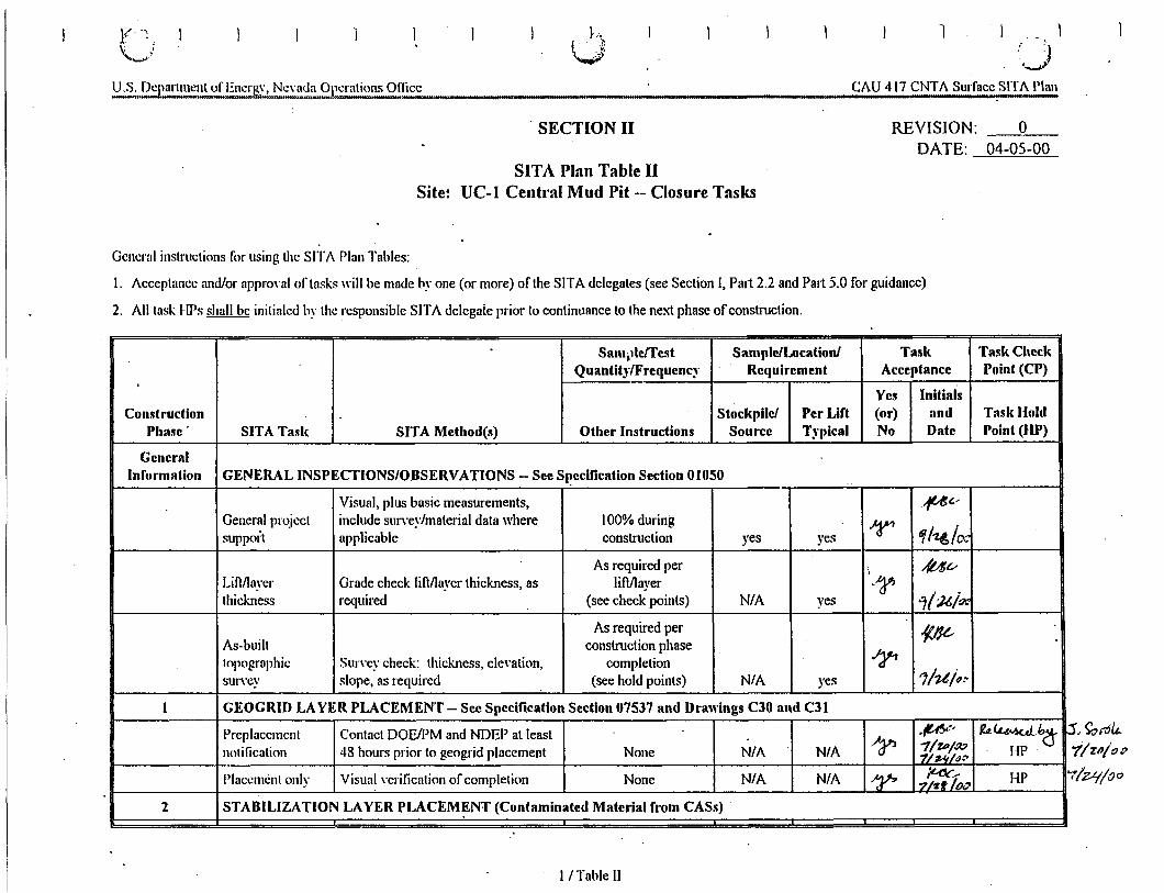
~,t ".~"v'
1 1:" :1oJ
CAU 417 CNTA Surface SITA Plan,..
. SECTION II REVISION:DATE:
o04-05-00
SITA Plan Table IISite: UC-I Central Mud Pit -- Closure Tasks
General instructions for using thc SITt\. Plan Tables:
I. Acceptance and/or approval of tasks will be made by one (or more) of the SITA delegates (see Section I, Part2.2 and Part 5.0 for guidance)
2. All task HPs shall bc initialed by the responsible SITA delegate prior to continuance to the next phase ofconstruction.
.~",u..7/zn/ot''IZ'(!oo
,Sam.llerrellt Sample/Location' Tasl( Task Check
Quantit~"/Frequenc~' Requirement Acceptance Point (CP),
Yes InitialsConstruction Stockpile/ Per Lift (or) and Task Hold
Phase SITA Tasl< SITA Method(s) Other Instructions Source Typical No Date Point (liP)
GeneralInformation GENERAL INSPECTIONS/OBSERVATlONS -- See Sl!ecification Section 01050
Visual, plus basic measurements, .#(.;General project inelude survey/material data where 100% during r tf17.1:,/0.support applicable construction yes yes
As required per ., ,,(ut--Liflllayer Grade check lift/layer thickness, as lift/layer ~~thickness required (see check points) N/A yes 1!uiq..
As required per~As-built construction.phase
.IJ'-'topographic SUITCY check: thickness, elevation, completionsurvey slope, as required (see hold points) N/A yes 1ht/~!'
1 GEOGRID LAYER PLACEMENT - See Specification Section 07537 and Drawings ClO and Cli
Preplacernent Contact DOEIPM and NDEP at least~~
.~.:/ ~~b(j- p"11Zt>//Xlnotification 48 hours prior to geogrid placement None NlA N/A 7j #-tij(JC'
. HP
Placement only Visual verification of completion Nonc N/A N/A ~ '7'::}!r» HP rr.
2 STABILIZATION LAYER PLACEM~NT(Contaminated Material from CASs)
II Table II
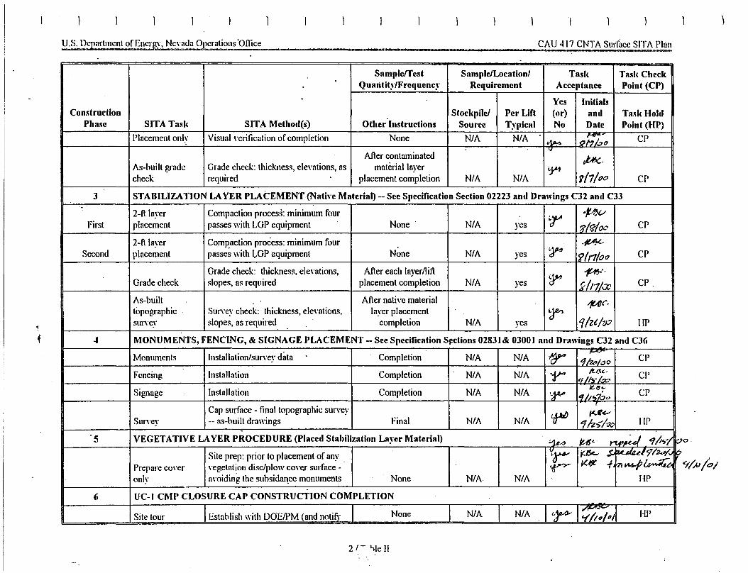
1IJ11111 II 111I.lImnlll III I 'I I II " III
CAU 417 CNTASurface SITA 1'1311II III1J IIU'''.I I 1 , 1.1t1."1
Samplcffest SllmplelLocationl Tasl{ Tasl{ Checl{Quantlty/Frequeney Requirement Acceptance Point (CP)
.Yes Initials
Construetkm Stocl{pilel Per Lift (or) and Ta,~k HoldPhase SITA Tusk SITA Method(s) Other'lnstructions Source Typical No Date Point (HP)
Placement only Visual verification of completion None N/A N/A~~ (;';;Z,o CP
Aftercontaminatedv
.J.~As-builtgrade Gradecheck: thickness,elevations,3S material layer ~YJ
check required placementcompletion N/A N/A 1(1/flo CP
3 STABILIZATION LAYER PLACEMENT (Native Material) -- See Specification Section 02223 and Drawings C32 and C33- 4AJv2-ft layer Compaction process: minimumfour
~First placement passes with LOP equipment None' N/A yes :?!!?Io<." CP
2-ft layer Compaction process: minimum four ~
Second placement passes with top equipment None N/A yes ~ 91""'/00 CP
Gradecheck: thickness,elevations, Aftereach layer/lift~
~l'
Gradecheck slopes, as required placementcompletion N/A yes x!nkrv CP,
As-built After nativematerial 1«/c.topographic Surveycheck: thickness,elevations, layerplacement ~survev slopes, as required completion N/A yes 1/zt/rv liP
.. MONUMENTS, FENCING, & SIGNAGE PLACEMENT -- See Specification Sections 02831& 03001 and Drawings C32 and C36
Monuments lnstallation/survev data Completion N/A N/A '~~,"'"
CP.' '1/U'lao
Fencing Installation Completion N/A N/A r /t-I!lc.. CPcll"la;.>
Signage Installation Completion N/A N/A ':~I!. " ... CPqh~'/~<>
Cap surface - final topographicsurveyr
~JA'bII,,~
SlIITey -- as-built drawings Final N/A N/A 11'Z~/rJC> III'.
'5 VEGETATIVE LAYER PROCEDURE (placed Stabilization Layer Material) .:.u", IU!< ~Ii~-I P'frv ;c.15c-- ... .~ .I·'<J/~/", ~Site prep: prior to placementof any -
Prepare cover vegetation disc/plow cover surface- .~Il~ -f 'rT04 .p/, 1:.
onlv avoidingthe subsidence monuments None NlA N/A HI'
6 lIC-1 CMP CLOSURE CAP CONSTRUCTION COMPLETION
Establish with DOEIPM (and notify None N/A N/A t;~ ~JOo- 1-11'Site tour t, ~It ,,/111
0,
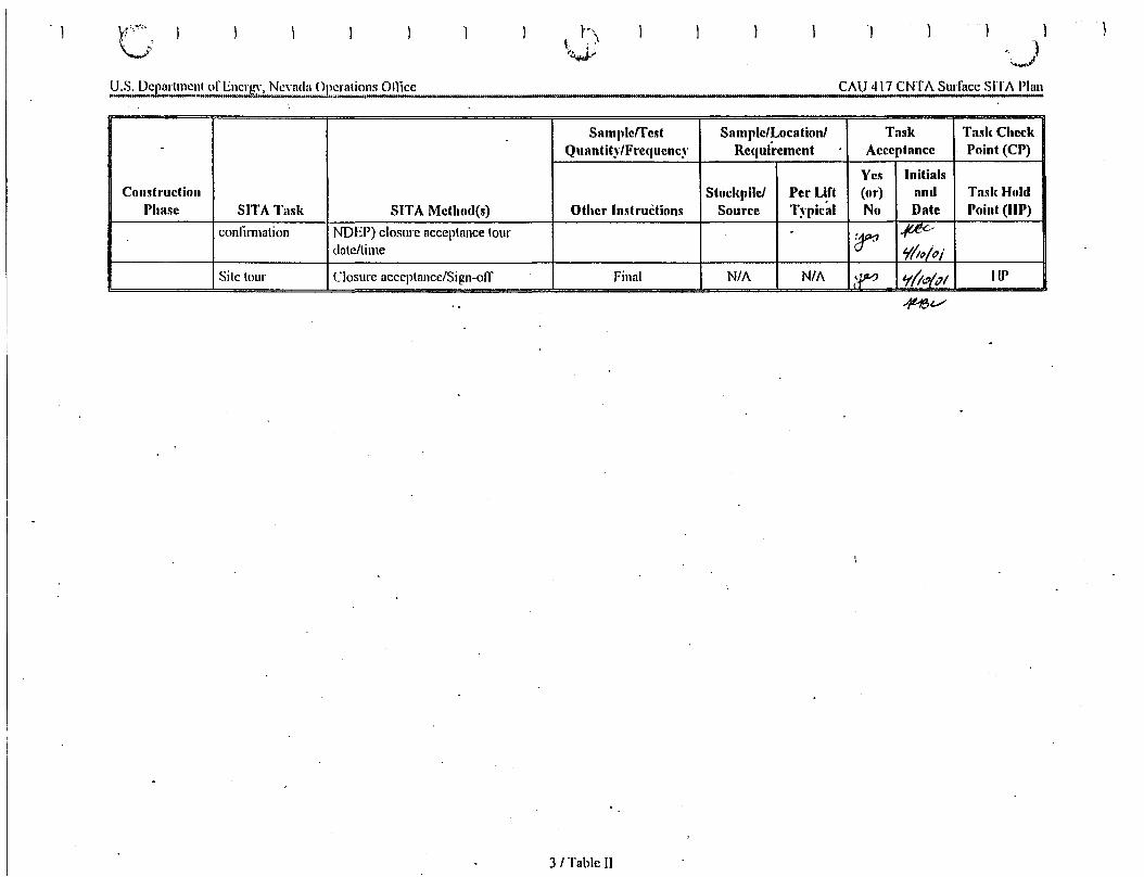
CAU 417 CNTA Surface SITA Plan
)
Samplerrest Sample/Location/ Task Tasl( Checl(- Quantit~'/Fre(IUenc~' Requirement Acceptance Point (CP)
Yes InitialsConstruction Stockpile! Per Lift (or) and Tad( Hold
Phase SITA Tllsli SITA Method(s) Other Instructions Source Typical No Date Point (liP)
confirmation NDEP)closure acceptance lour . ;r ~"dale/lime ¥/I~/oi
Site lour Closure acceptance/Sign-off Final N/A N/A I~ o/(;lP/P/ UP
3/ Table II
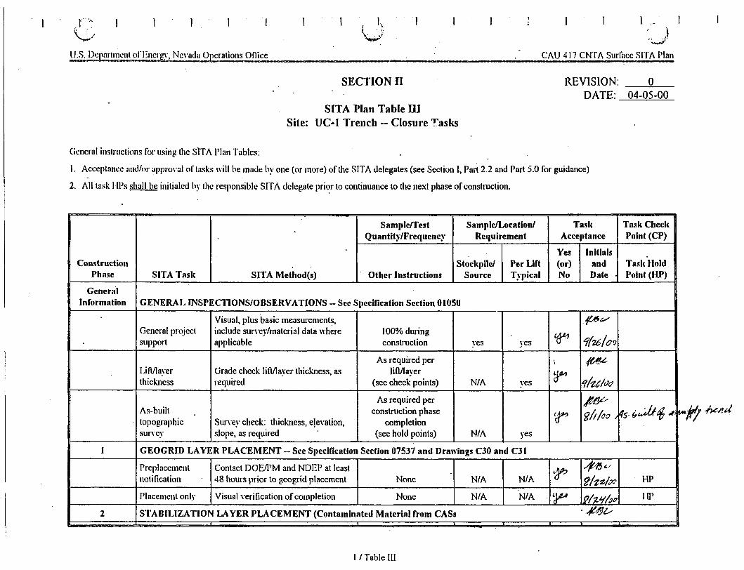
r-(...>
I, ).:-;t'
CI\.U 417 CNTI\. Surface SITI\. Plan
SECTION II
SITA Plan Table IIISite: Ve·l Trench -- Closure Tasks
REVISION:DATE:
o04-05-00
General instructions for using the sITI\. PlanTables:
I. Acceptance and/or approval of tasks willbe made by one (or more)of the SITA delegates(see SectionI, Part 2.2 and Part 5.0 for guidance)
2. All task ID)s shall be initialed by the responsibleSITI\. delegate pri~r to continuance to the next phaseof construction.
Sample/Test Sample/Locationl Tasl, Tasl, CheckQuantit~'/Frequenc~' Requirement Acccptance Point (CP)
Yes InitialsConstruction Stockpile! Per Lift (or) and TalikHold
Phase SITA Talil, SITA Method(s) Other Instructions Source Typical No Date Point (HP)
GeneralInformation GENERAL INSPECTIONSIOBSERVATIONS - See Specfflcation Section 01050
Visual, plus basic measurements, .pvGeneral project includesurvey/material data where 100%during
cera 1(1£/00support applicable construction yes yes
As required per \ ~Lift/layer Gradecheck liMayer thickness, as lifl/layer ?" 1lzt/tJiJthickness required (see check points) N/A yes
As required per /l1¥/~S-b~tf; J
As-built construction phase Ir glt/'"0 , It.tttopographic Surveycheck: thickness,elevation, completionsun'ey slope, as required (see hold points) N/A yes
I GEOGRID LAYER PLACEMENT -- See Specification Section 07537 and Drawings C30 and C31
Preplacement ContactDOEIPM and NDEP at least 'JP.'41!Jt./
notification 48 hours prior to geogridplacement None NIA N/A ~Izz/~C' HP
Placement only Visual verification of completion None NIA N/A ~ 191't'l1~/? 10'
2 STABILIZATION LAYER PLACEMENT (Contaminatcd Material from CASs . .{t~v
II Table III
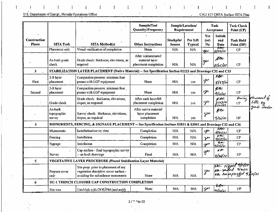
I
CAU 417 CNTA Surface SITA Plan
Sample/Test Sample/Location/ Task Task CheckQuantity/Frequency Requirement Acceptance Point (CP)
- Yell InitialsConstruction Stockpile/ Per Lift (or) and Task Hold
Phase SITA Task SITA Method(s) Other Instructions Source Typical No Date Point (HP)Placement only Visual verification of completion None N/A N/A ~
CPI~ J?iz'7/cJr:lAfter contaminated
II~As-built grade Grade check: thickness, elevations, as material layer r:check required placement completion N/A N/A fh5"/f};J CP
3 . STABILIZATION LAYER PLACEMENT (Native Material) - See Specification Section 02223 and Drawings C32 and C33
2-fi layer Compaction process: minimun four ~
First placement passes with LGP equipment None N/A yes t-JM f(?'7/.:n CP
2-tt layer Compaction process: minimun four "
"1""~-
Second placement passes with LGP equipment None N/A yes ti)/;/~" CP
Grade check: thickness, elevations, After each layer/lift fU$e~ PUYJ"j '"Grade check slopes, as required placement completion N/A yes tr' ror/« CP6/, ,/~"
As-built After native material ,ft"3vtopographic Survey check: thickness, elevations, layer placement 'r6'survev slopes, as required completion N/A yes 1/u! (J;.'> IlP
... MONUMENTS, FENCING, & SIGNAGE PLACEMENT - See Specification Sections 02831 & 03001 and Drawings C32 and C36
Monuments Installation/survev data Completion N/A N/A .~~Mf?V
CP4'/zoj~;)
Fencing Installation Completion N/A N/A 'P"~ CP-?ji"i4fJ
Signage Installation Completion N/A N/A t..¥4-ft..hL--
CP'1115/"-,,Cap surface - final topographic survey
~Jt,d'"
Survey -- as-built drawings Final N/A N/A 1t;lu/,;p liP
5 VEGETATIVE LAYER PROCEDURE (Placed Stabilization Layer Material) . J
Site prep: prior to placement of any ~t_ rt r,;u.4 ?({)(J<l
Prepare cover vegetation disc/plow cover surface - r #-' -;,p... !'cI 'T/£'JIII,;1
onlv avoiding the subsidance monuments None N/A N/A U" /Yi! 'rtJrller~~/l'/
6 UC-l TRENCH CLOSURE CAP CONSTRUCTION COMPLETIONJ.
Establish with DOEiPM (and notify None N/A N/A ~, .. rw
IlPSite tour I,..~. J
2/ T·I-,Ie III
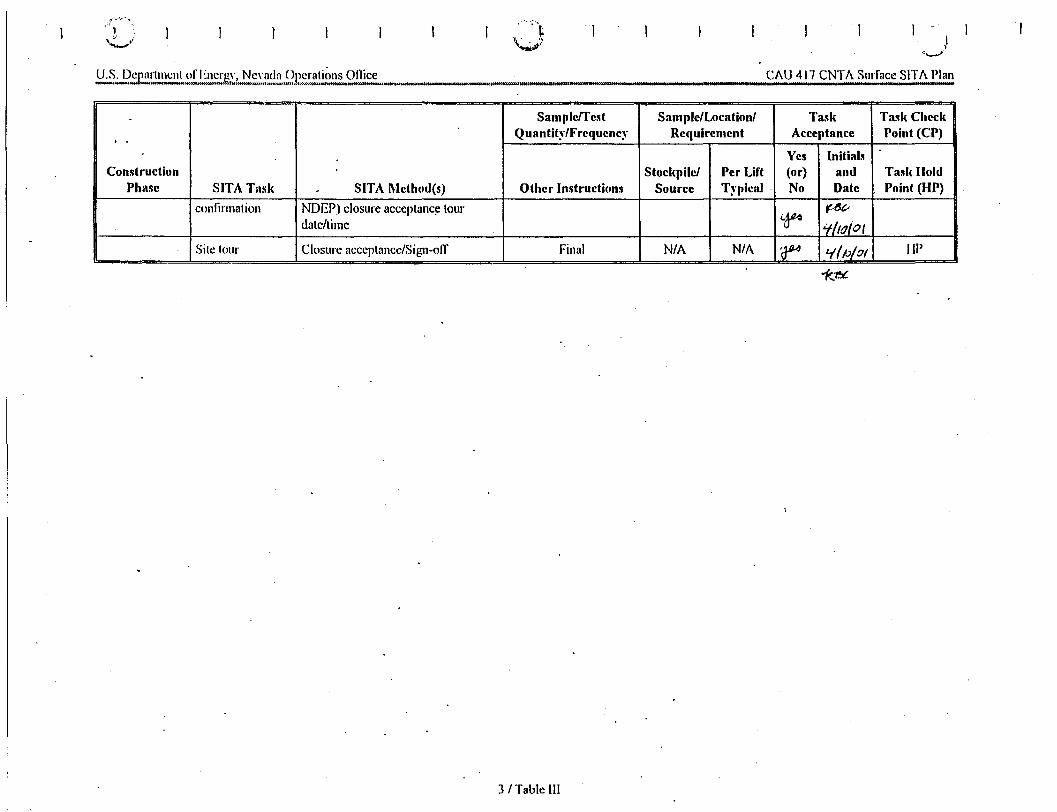
·~.: ..
.-1-..CAU 417 CNTA Surface SITA Plan
Sample/Test Sample/Location/ Task Task Check
. - Quantit~·/Frequenc~· Requirement Acceptance Point (CP)
Yes InitialsConstruction Stoc!<pile/ Per Lift (or) and Tasl< Hold
Phase SITA Tllsl< - SITA Method(s) Other Instructions Source Typical No Date Point (HP)
confirmation NDEP) closure acceptance tour(.~
f.-{jc"
date/time if/IdIotSite tour Closure acceptance/Sign-off Final N/A N/A ~ Lf/p/.71 lIP
3 I Table III
APPENDIXH
POST-CLOSURE INSPECTION CHECKLISTS
THIS PAGE INTENTIONALLY LEFT BLANK
•
•
•..
•
•..
III
..•
•
..

CAU 417: CNTA UC-1 CENTRAL MUD PIT COVER, POST-CLOSURE MONITORING CHECKLIST
Date of Last Inspection: Reason for Last Inspection:
Responsible Agency: Project Manager:
Inspection Date:
Inspector (name, title, oroanlzation):
Assistant Inspector (name, title, oraanization):
A. GENERAL INSTRUCTIONS1. All checklist items must be completed and detailed comments made to document the results of the site inspection. The
completed checklist is part of the field record of the inspection. Additional pages should be used as necessary to ensurethat a complete record is made. Attach the additional pages and number all pages upon completion of the inspection.
3. Any checklist line item marked by an inspector in a SHADED BOX, must be fUlly explained or an appropriate reference toprevious reports provided. The purpose of this requirement is to provide a written explanation of inspector observationsand the inspector's rationale for conclusions and recommendations. Explanations are to be placed on additionalattachments and cross-referenced appropriately. Explanations, in addition to narrative, will take the form of sketches,measurements, annotated site maps.
4. The site inspection is a walking inspection of the entire site including the perimeter and sufficient transects to be able toinspect the entire surface and all features specifically described in this checklist.
5. A standard set of color 35 mm photographs (or equivalent) is required. In addition, all anomalous features or new features(such as changes in adjacent area land use) are to be photographed. A photo log entry will be made for each photographtaken.
6. This unit will be inspected biannually with formal reporting to the Nevada Division of Environmental Protection to be doneannually. The annual report will include an executive summary, this inspection checklist with field notes and photo logattached, and recommendations and conclusions.
B. PREPARATION (To be completed prior to site visit) YES NO EXPLANATION
1. .Site as-built plans and site base map reviewed.
2. Previous inspection reports reviewed.
a. Were anomalies or trends detected on previousinspections?
b. Was maintenance performed?
3. Site maintenance and repair records reviewed.
a. Has site repair resulted in a change from as-builtconditions?
b. Are revised as-builts available that reflect repair changes?
C. SITE INSPECTION (To be completed during inspection) YES NO EXPLANATION
1. Adjacent off-site features within watershed areas.
a. Have there been any changes in use of adjacent area?
b. Are there any new roads or trails?
c. Has there been a change in the position of nearbywashes?
d. Has there been lateral excursion or erosion/deposition ofnearby washes?
e. Are there new drainage channels?
f. Change in surrounding vegetation?
2. Security fence, signs.
a. Displacement of fences, site markers, boundary markers,or monuments?
b. Have any signs been damaged or removed?(Number of signs replaced: )
c. Were gates locked?
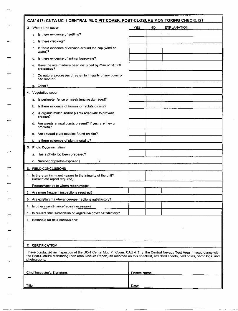
CAU 417: CNTA UC-1 CENTRAL MUD PIT COVER, POST-CLOSURE MONITORING CHECKLIST
3. Waste Unit cover. YES NO EXPLANATION
a. Is there evidence of settling?
b. Is there cracking?
c. Is there evidence of erosion around the cap (wind orwater)?
d. Is there evidence of animal burrowing?
e. Have the site markers been disturbed by man or naturalprocesses?
f. Do natural processes threaten to integrity of any cover orsite marker?
a. Other?
4. Vegetative cover.
a. Is perimeter fence or mesh fencing damaged?
b. Is there evidence of horses or rabbits on site?
c. Is organic mulch and/or plants adequate to preventerosion?
d. Are weedy annual plants present? If yes, are they aproblem?
e. Are seeded plant species found on site?
f. Is there evidence of olant mortality?
5. Photo Documentation
a. Has a photo log been prepared?
c. Number of photos exoosed I )
D. FIELD CONCLUSIONS
1. Is there an imminent hazard to the integrity of the unit?(Immediate report required)
Person/AaencY to whom reoort made:
2. Are more freauent insoections reauired?
3. Are existing maintenance/repair actions satisfactory?
4. Is other maintenance/repair necessary?
5. Is current status/condition of veaetative cover satisfactory?
6. Rationale for field conclusions:
E. CERTIFICATION
I have conducted an inspection of the UC-1 Cental Mud Pit Cover, CAU 417, at the Central Nevada Test Area in accordance withthe Post-Closure Monitoring Plan (see Closure Report) as recorded on this checklist, attached sheets, field notes, photo logs, andohotoaraohs.
Chief Insoector's Sianature: Printed Name:
Title: Date:
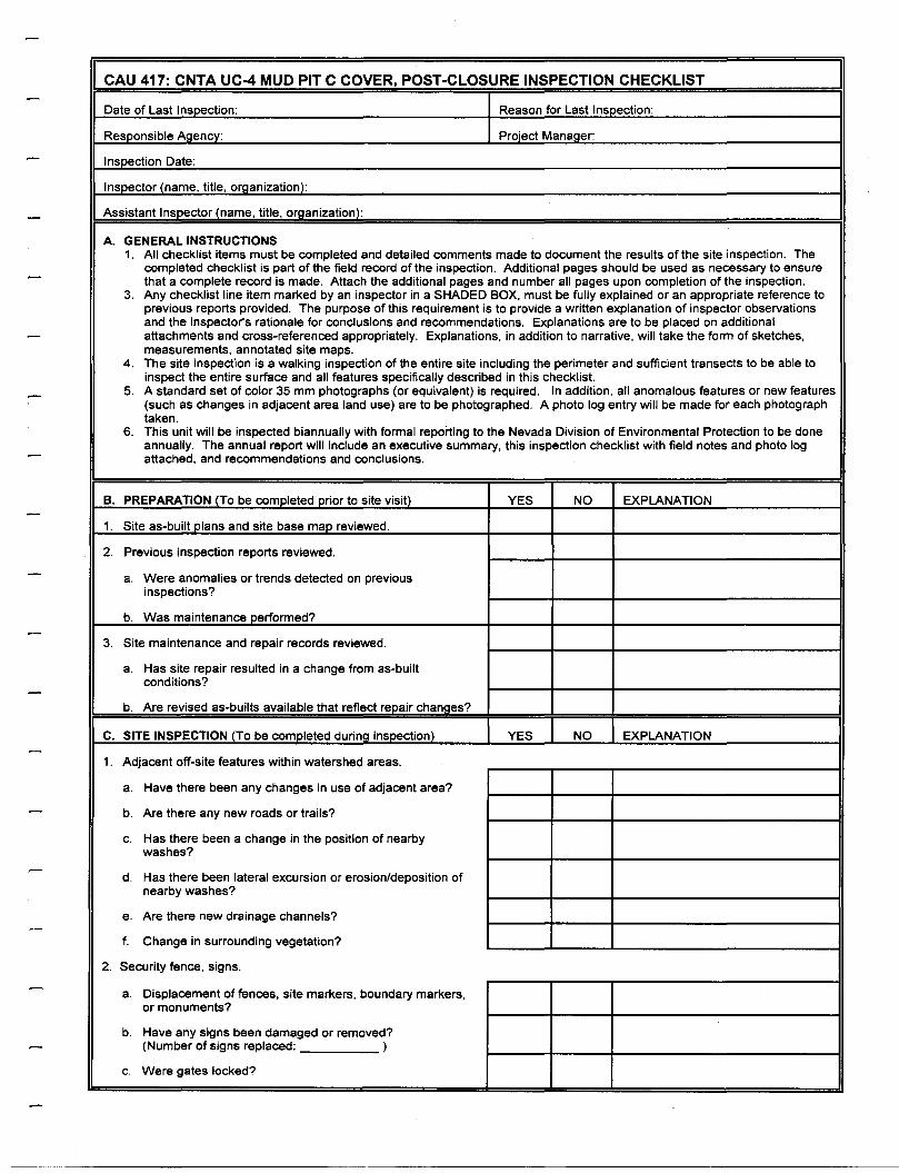
CAU 417: CNTA UC-4 MUD PIT C COVER, POST-CLOSURE INSPECTION CHECKLIST
Date of Last Inspection: Reason for Last Insoection:
Responsible Agency: Project Manager:
Inspection Date:
Inspector (name, title, organization):
Assistant Inspector (name, title, organization):
A. GENERAL INSTRUCTIONS1. All checklist items must be completed and detailed comments made to document the results of the site inspection. The
completed checklist is part of the field record of the inspection. Additional pages should be used as necessary to ensurethat a complete record is made. Attach the additional pages and number all pages upon completion of the inspection.
3. Any checklist line item marked by an inspector in a SHADED BOX, must be fully explained or an appropriate reference toprevious reports provided. The purpose of this requirement is to provide a written explanation of inspector observationsand the inspector's rationale for conclusions and recommendations. Explanations are to be placed on additionalattachments and cross-referenced appropriately. Explanations, in addition to narrative, will take the form of sketches,measurements, annotated site maps.
4. The site inspection is a walking inspection of the entire site including the perimeter and sufficient transects to be able toinspect the entire surface and all features specifically described in this checklist.
5. A standard set of color 35 mm photographs (or equivalent) is required. In addition, all anomalous features or new features(such as changes in adjacent area land use) are to be photographed. A photo log entry will be made for each photographtaken.
6. This unit will be inspected biannually with formal reporting to the Nevada Division of Environmental Protection to be doneannually. The annual report will include an executive summary, this inspection checklist with field notes and photo logattached, and recommendations and conclusions.
B. PREPARATION (To be completed prior to site visit) YES NO EXPLANATION
1. Site as-built plans and site base map reviewed.
2. Previous inspection reports reviewed.
a. Were anomalies or trends detected on previousinspections?
b. Was maintenance performed?
3. Site maintenance and repair records reviewed.
a. Has site repair resulted in a change from as-builtconditions?
b. Are revised as-builts available that reflect reoair chances?
C. SITE INSPECTION (To be comoleted durina insoection) YES NO EXPLANATION
1. Adjacent off-site features within watershed areas.
a. Have there been any changes in use of adjacent area?
b. Are there any new roads or trails?
c. Has there been a change in the position of nearbywashes?
d. Has there been lateral excursion or erosion/deposition ofnearby washes?
e. Are there new drainage channels?
f. Change in surrounding vegetation?
2. Security fence, signs.
a. Displacement of fences, site markers, boundary markers,or monuments?
b. Have any signs been damaged or removed?(Number of signs replaced: )
c. Were gates locked?
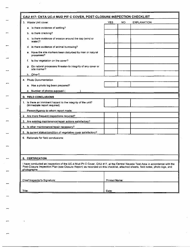
CAU 417: CNTA UC-4 MUD PIT C COVER, POST-CLOSURE INSPECTION CHECKLIST
3. Waste Unit cover. YES NO EXPLANATION
a. Is there evidence of settling?
b. Is there cracking?
c. Is there evidence of erosion around the cap (wind orwater)?
d. Is there evidence of animal burrowing?
e. Have the site markers been disturbed by man or naturalprocesses?
f. Is the vegetation on the cover?
g. Do natural processes threaten to integrity of any cover orsite marker?
h. Other?
4. Photo Documentation
a. Has a photo log been prepared?
c. Number of photos exposed ( )
D. FIELD CONCLUSIONS
1. Is there an imminent hazard to the integrity of the unit?(Immediate report required)
Person/Aaencv to whom report made:
2. Are more freauent insoections required?
3. Are existina maintenance/repair actions satisfactory?
4. Is other maintenance/repair necessary?
5. Is current status/condition of veaetative cover satisfactory?
6. Rationale for field conclusions:
E. CERTIFICATION
I have conducted an inspection of the UC-4 Mud Pit C Cover, CAU 417, at the Central Nevada Test Area in accordance with thePost-Closure Inspection Plan (see Closure Report) as recorded on this checklist, attached sheets, field notes, photo logs, andphotocraohs.
Chief Insoector's Sianature: Printed Name:
Title: Date:
APPENDIX I
NDEP DOCUMENT REVIEW SHEET

THIS PAGE INTENTIONALLY LEFT BLANK
•
•
•••
•
III
•III
••
••••
•III
•
•
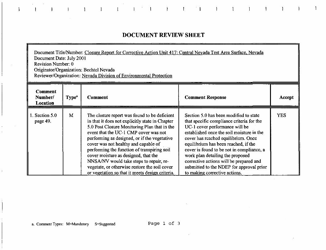
DOCUMENT REVIEW SHEET
1
Document TitlelNumber: Closure Report for Corrective Action Unit 417: Central Nevada Test Area Surface, NevadaDocument Date: July 2001Revision Number: 0Originator/Organization: Bechtel NevadaReviewer/Organization: Nevada Division of Environmental Protection
CommentNumber/ Typea Comment Comment Response AcceptLocation
1. Section 5.0 M The closure report was found to be deficient Section 5.0 has been modified to state YESpage 49. in that it does not explicitly state in Chapter that specific compliance criteria for the
5.0 Post Closure Monitoring Plan that in the UC-1 cover performance will beevent that the UC-1 CMP cover was not established once the soil moisture in theperforming as designed, or if the vegetative cover has reached equilibrium. Oncecover was not healthy and capable of equilibrium has been reached, if theperforming the function of transpiring soil cover is found to be not in compliance, acover moisture as designed, that the work plan detailing the proposedNNSAINV would take steps to repair, re- corrective actions will be prepared andvegetate, or otherwise restore the soil cover submitted to the NDEP for approval prioror vegetation so that it meets design criteria. to making corrective actions.
a. Comment Types: M=Mandatory S=Suggested Page 1 of 3
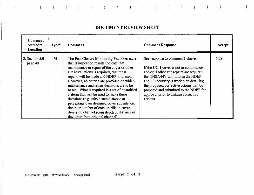
1
DOCUMENT REVIEW SHEET
)
CommentNumberl Type" Comment Comment Response AcceptLocation
2. Seciton 5.0 M The Post Closure Monitoring Plan does state See response to comment 1 above. YESpage 49 that if inspection results indicate that
maintenance or repair of the cover or other If the UC-l cover is not in compliancesite installations is required, that those and/or if other site repairs are requiredrepairs will be made and NDEP informed. the NNSAINV will inform the NDEPHowever, no criteria are provided on which and, if necessary, a work plan detailingmaintenance and repair decisions are to be the proposed corrective actions will bebased. What is required is a set of quantified prepared and submitted to the NDEP forcriteria that will be used to make these approval prior to making correctivedecisions (e.g. subsidence distance or actions.percentage over designed cover subsidence,depth or number of erosion rills in cover,diversion channel scour depth or distance ofdeviation from original channel).
a. CommentTypes: M=Mandatory S=Suggested Page 2 of 3
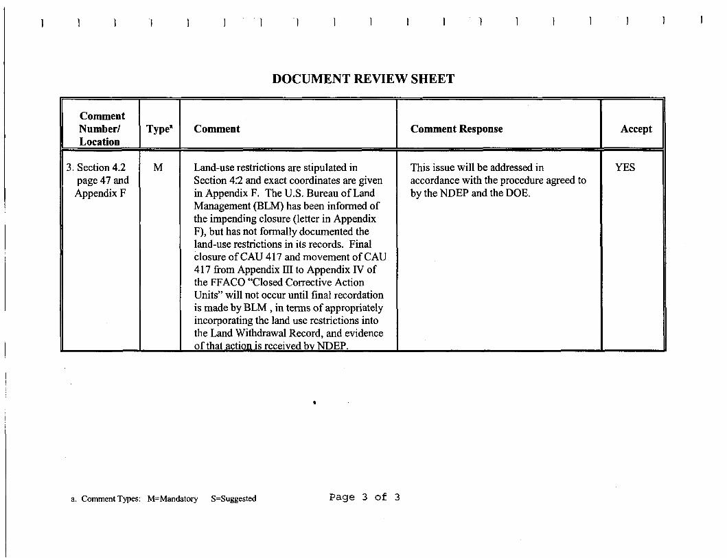
DOCUMENT REVIEW SHEET
CommentNumber! Typea Comment Comment Response AcceptLocation
3. Section 4.2 M Land-use restrictions are stipulated in This issue will be addressed in YESpage 47 and Section 4:2 and exact coordinates are given accordance with the procedure agreed toAppendix F in Appendix F. The U.S. Bureau of Land by the NDEP and the DOE.
Management (BLM) has been informed ofthe impending closure (letter in AppendixF), but has not formally documented theland-use restrictions in its records. Finalclosure of CAU 417 and movement of CAU417 from Appendix Ill to Appendix IV ofthe FFACO "Closed Corrective ActionUnits" will not occur until final recordationis made by BLM , in terms of appropriatelyincorporating the land use restrictions intothe Land Withdrawal Record, and evidenceofthat action is received bv NDEP.
•
a. CommentTypes: M=Mandatory S=Suggested Page 3 of 3

This page intentionally left blank
DISTRIBUTION LIST
THIS PAGE INTENTIONALLY LEFT BLANK
•
•
•
••
•••
•
••••
•
•
..•
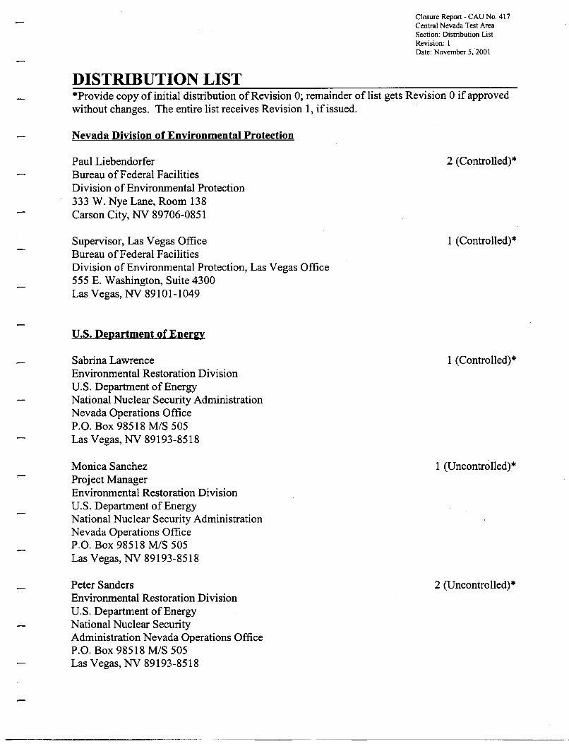
Closure Report - CAU No. 417Central Nevada Test AreaSection: Distribution ListRevision: 1Date: November 5. 2001
DISTRIBUTION LIST*Provide copy of initial distribution ofRevision 0; remainder of list gets Revision 0 if approvedwithout changes. The entire list receives Revision 1, if issued.
Nevada Division of Environmental Protection
Paul LiebendorferBureau ofFederal FacilitiesDivision of Environmental Protection333 W. Nye Lane, Room 138Carson City, NY 89706-0851
Supervisor, Las Vegas OfficeBureau ofFederal FacilitiesDivision of Environmental Protection, Las Vegas Office555 E. Washington, Suite 4300Las Vegas, NY 89101-1049
U.S. Department of Ener2Y
Sabrina LawrenceEnvironmental Restoration DivisionU.S. Department of EnergyNational Nuclear Security AdministrationNevada Operations OfficeP.O. Box 98518 MIS 505Las Vegas, NY 89193-8518
Monica SanchezProject ManagerEnvironmental Restoration DivisionU.S. Department of EnergyNational Nuclear Security AdministrationNevada Operations OfficeP.O. Box 98518 MIS 505Las Vegas, NY 89193-8518
Peter SandersEnvironmental Restoration DivisionU.S. Department ofEnergyNational Nuclear SecurityAdministration Nevada Operations OfficeP.O. Box 98518 MIS 505Las Vegas, NY 89193-8518
2 (Controlled)*
1 (Controlled)*
1 (Controlled)*
1 (Uncontrolled)*
2 (Uncontrolled)*
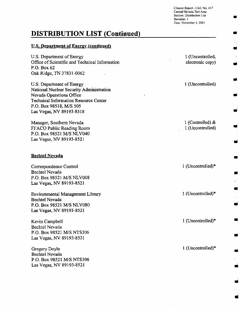
Closure Report - CAU No. 417Central Nevada Test AreaSection: Distribution List •Revision: IDate: November 5. 2001
DISTRIBUTION LIST (Continued) •u.s. Department of EnereY (continued) III
U.S. Department of Energy 1 (Uncontrolled,Office of Scientific and Technical Information electronic copy) •P.O. Box 62Oak Ridge, TN 37831-0062
•U.S. Department of Energy 1 (Uncontrolled)National Nuclear Security AdministrationNevada Operations Office •Technical Information Resource CenterP.O. Box 98518, MIS 505Las Vegas, NV 89193-8518 •Manager, Southern Nevada 1 (Controlled) & ..FFACO Public Reading Room 1 (Uncontrolled)P.O. Box 98521 MIS NLV040Las Vegas, NV 89193-8521 ..Bechtel Nevada •Correspondence Control 1 (Uncontrolled)*Bechtel Nevada IIIP.O. Box 98521 MIS NLVOO8Las Vegas, NV 89193-8521
•Environmental Management Library 1 (Uncontrolled)*Bechtel NevadaP.O. Box 98521 MIS NLV080 IIILas Vegas, NV 89193-8521
Kevin Campbell 1 (Uncontrolled)* III
Bechtel NevadaP.O. Box 98521 MIS NTS306 ..Las Vegas, NV 89193-8521
Gregory Doyle 1 (Uncontrolled)*III
Bechtel NevadaP.O. Box 98521 MIS NTS306Las Vegas, NV 89193-8521 ..
III
DISTRIBUTION LIST (Continued)
Bechtel Nevada (continued)
Ann HeidemaBechtel NevadaP.O. Box 98521 MIS NLV102Las Vegas, NY 89193-8521
Wayne JohnsonBechtel NevadaP.O. Box 98521 MIS NTS306Las Vegas, NY 89193-8521
Steve NachtBechtel NevadaP.O. Box 98521 MIS NTS306Las Vegas, NY 89193-8521
Julie SorolaBechtel NevadaP.O. Box 98521 MIS NLV085Las Vegas, NY 89193-8521
IT Corporation
GanyRomanoIT FFACO Support OfficeIT CorporationP.O. Box 93838, MIS 439Las Vegas, NY 89193-3838
David StahlIT CorporationP.O. Box 93838, MIS 439Las Vegas, NY 89193-3838
PEER Consultants
Gary HudakPEER ConsultantsP.O. Box 98521 MIS NLV082Las Vegas, NY 89193-8521
Closure Report - CAU No. 417Central Nevada Test AreaSection: Distribution ListRevision: IDate: November 5, 2001
1 (Uncontrolled)"
1 (Uncontrolled)*
1 (Uncontrolled)*
1 (Uncontrolled)*
1 (Controlled)
1 (Uncontrolled)*
1 (Uncontrolled)*

DISTRIBUTION LIST (Continued)
State of Nevada
Manager, Northern NevadaFFACO Public Reading RoomNevada State Library and Archives, Federal Publications100 North Stewart StreetCarson City, NY 89701-4284
u.S. Bureau of Land Mana&ement
William S. FisherP.O. Box 911Tonopah, NY 89049-0911
u.S. Forest Service
John HaneyTonopah Ranger DistrictP.O. Box 3940Tonopah, NY 89049-6286
Closure Report - CAU No. 417Central Nevada Test AreaSection: Distribution ListRevision: 1Date: November 5, 2001
1 (Uncontrolled)
1 (Uncontrolled)
1 (Uncontrolled)
•
•
•
••........•
..•IIIiI
IIIiI
..