Embed Size (px)
Citation preview

National Crane Series 1400AProduct GuideASME B30.5Imperial 85%
Features
• 29,9 t (33 USt) rating
• 38,72 m (127 ft) five-section boom
• Self-lubricating “Easy Glide” wear pads
• Internal anti-two-block
• Vision™ cab

Features
Five-section boomAt 38,72 m (127 ft), the Series 1400A five-section boom is the longest in its size range. The long boom allows the operator to perform more lifts without the use of a jib, reducing setup time and improving efficiency. Also available are optional four-section boom lengths of 30,5 m (100 ft) and 33,5 m (110 ft).
OutriggersTwo sets of “H” style outriggers with 7,47 m (24 ft 6 in) span, with removable ball and socket aluminum foot pads. Independent controls located on each side of the crane can be positioned at mid-span setting of 5,18 m (17 ft). Single front stabilizer (SFO) comes with first-up feature.
Deluxe operator’s cabVision Cab™ has a rigid powder coated steel structure, is well insulated, with ample safety glass for operator visibility and comfort. Multi-position seat with arm rest single axis controls, ventilation fans, diesel heater, and wipers. Optional air conditioning is available. Optional open-seat control station in lieu of enclosed cab is available.
Overload protectionAll National Crane boom trucks are equipped with
overload protection. A Load Moment Indicator (LMI) is standard on all Series 1400A machines. The LMI display console with Work Area Definition System
(WADS) is weatherproof. The LCD display is visible in full or low light and displays all crane load lifting
values simultaneously.
National Crane Series 1400A
• 29,9 t (33 USt) maximum capacity• 41,15 m (135 ft) maximum tip height (main boom)• 52,43 m (172 ft) maximum tip height (boom with jib)

Features
Best in class performance and serviceability
• The stronger standard torsion box improves rigidity, reduces truck frame flex and reduces the need for counterweight.
• Easy Glide Boom Wear Pads reduce the conditions that cause boom chatter and vibration. The net result is smoother crane operation.
• Speedy-reeve boom tip and sheave blocks simplify rigging changes by decreasing the time needed to change line reeving.
• Crane components painted before assembly reduce the chance of rust, improve serviceability and enhance the appearance of the crane.
• Internal anti-two block wiring standard on the 1400A routes the wiring through the inside of the boom eliminating the possibility of snagging the wire on obstructions.
• Bearings on the boom and retract cables can be greased through access holes in the boom side plates and number of internal boom parts has been reduced improving serviceability.
• The Series 1400A is supplied with continuous rotation standard, along with the “glide swing” feature, allowing free swing during rotation, and a manually applied foot brake.
• Adjustable swing speed comes standard on the 1400A. A control knob located on the swing motor brake release valve can be easily adjusted to the crane operator’s swing speed preference.
• Oil cooler mounted at boom rest with electric fan is standard.
• Pressure compensated hydraulic system control valves come with load-sensing variable displacement piston pump.
*Product may be shown with optional equipment.

4
Contents
Mounting configurations 5
Specifications 6
Capacities 8
Dimensions specifications 11
Accessories 12
5Series 1400A
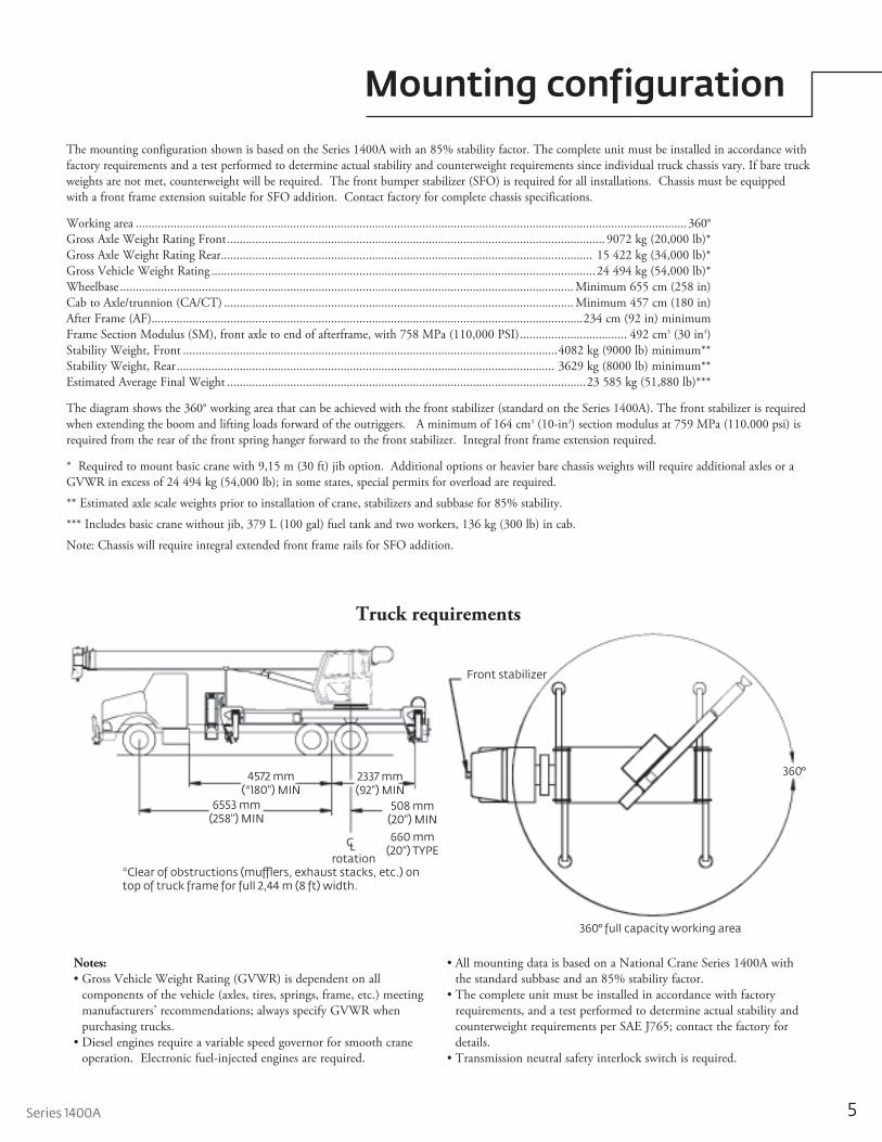
Mounting configuration
The mounting con fig u ra tion shown is based on the Series 1400A with an 85% stability factor. The com plete unit must be installed in accordance with factory re quire ments and a test per formed to determine actual stability and coun ter weight requirements since individual truck chassis vary. If bare truck weights are not met, counterweight will be required. The front bumper stabilizer (SFO) is required for all installations. Chassis must be equipped with a front frame extension suitable for SFO addition. Contact factory for complete chassis specifications.
Working area ............................................................................................................................................................................... 360°Gross Axle Weight Rating Front ........................................................................................................................ 9072 kg (20,000 lb)*Gross Axle Weight Rating Rear...................................................................................................................... 15 422 kg (34,000 lb)*Gross Vehicle Weight Rating ..........................................................................................................................24 494 kg (54,000 lb)*Wheelbase ................................................................................................................................................ Minimum 655 cm (258 in)Cab to Axle/trunnion (CA/CT) ............................................................................................................... Minimum 457 cm (180 in)After Frame (AF).........................................................................................................................................234 cm (92 in) minimumFrame Section Modulus (SM), front axle to end of afterframe, with 758 MPa (110,000 PSI) .................................. 492 cm3 (30 in3)Stability Weight, Front .......................................................................................................................4082 kg (9000 lb) minimum**Stability Weight, Rear ........................................................................................................................ 3629 kg (8000 lb) minimum**Estimated Average Final Weight ..................................................................................................................23 585 kg (51,880 lb)***
The diagram shows the 360° working area that can be achieved with the front stabilizer (standard on the Series 1400A). The front stabilizer is required when extending the boom and lifting loads forward of the outriggers. A minimum of 164 cm3 (10-in3) section modulus at 759 MPa (110,000 psi) is required from the rear of the front spring hanger forward to the front stabilizer. Integral front frame extension required.
* Required to mount basic crane with 9,15 m (30 ft) jib option. Additional options or heavier bare chassis weights will require additional axles or a GVWR in excess of 24 494 kg (54,000 lb); in some states, special permits for overload are required.
** Estimated axle scale weights prior to installation of crane, stabilizers and subbase for 85% stability.
*** Includes basic crane without jib, 379 L (100 gal) fuel tank and two workers, 136 kg (300 lb) in cab.
Note: Chassis will require integral extended front frame rails for SFO addition.
Notes:• Gross Vehicle Weight Rating (GVWR) is dependent on all
components of the vehicle (axles, tires, springs, frame, etc.) meeting manufacturers’ recommendations; always specify GVWR when purchasing trucks.
• Diesel engines require a variable speed governor for smooth crane operation. Electronic fuel-injected engines are required.
• All mounting data is based on a National Crane Series 1400A with the standard subbase and an 85% stability factor.
• The complete unit must be installed in accordance with factory requirements, and a test performed to determine actual stability and counterweight requirements per SAE J765; contact the factory for details.
• Transmission neutral safety interlock switch is required.
Front stabilizer
360°2337 mm(92") MIN
508 mm(20") MIN
4572 mm(*180") MIN
6553 mm(258") MIN
C 660 mm(20") TYPEL
rotation*Clear of obstructions (mufflers, exhaust stacks, etc.) on top of truck frame for full 2,44 m (8 ft) width.
360° full capacity working area
Truck requirements

6
Specifications
Boom and jib combinations data
Note: Maximum tip is measured with outriggers/stabilizers fully extended.
Model 14110A — Equipped with a 10,16 m - 33,53 m (33 ft 4 in - 110 ft) four-section boom. This model can be equipped with a 9,15 m (30 ft) single section jib or a 9,15 m - 16,46 m (30 ft - 54 ft) two-section jib. Max i mum tip height with 9,15 m (30 ft) jib is 44,82 m (147 ft), while maximum tip height with 16,46 m (54 ft) jib is 52,13 m (171 ft).
Available in three basic models.
Model 14127A — Equipped with a 9,63 m - 38,72 m (31 ft 7 in - 127 ft) five-section boom. This model can be equipped with a 9,15 m (30 ft) single-section jib. Maximum tip height with 9,15 m (30 ft) jib is 50,00 m (164 ft).
14FJ54M 9,15 m - 16,46 m (30 ft - 54 ft) two-section jib 10,16 m - 33,53 m (33 ft 4 in - 110 ft) four-section boom
9,63 m - 38,72 m (31 ft 7 in - 127 ft) five-section boom 14FJ30M 9,15 m (30 ft) single-section jib
Model 14100A — Equipped with a 9,40 m - 30,49 m (30 ft 10 in - 100 ft) four-section boom. This model can be equipped with a 9,15 m (30 ft) single-section jib or a 9,15 m - 16,46 m (30 ft - 54 ft) two-section jib. Max i mum tip height with 9,15 m (30 ft) jib is 41,77 m (137 ft), while maximum tip height with 9,15 m - 16,46 m (30 ft - 54 ft) jib is 49,08 m (161 ft).
14FJ54M 9,15 m - 16,46 m (30 ft - 54 ft) two-section jib 9,40 m - 30,49 m (30 ft 10 in - 100 ft) four-section boom
14FJ30M 9,15 m (30 ft) single-section jib9,40 m - 30,49 m (30 ft 10 in - 100 ft) four-section boom
14FJ30M 9,15 m (30 ft) single-section jib10,16 m - 33,53 m (33 ft 4 in - 110 ft) four-section boom

1 part line 2 part line 3 part line 4 part line 5 part line 6 part line 7 part line 8 part line
7Series 1400A
Specifications
THIS CHART IS ONLY A GUIDE AND SHOULD NOT BE USED TO OPERATE THE CRANE. The individual crane’s load chart, operating instructions and other instructional plates must be read and understood prior to operating the crane.
1400A winch data
Winch Cable supplied
Average breaking strength
Lift and
speed
Lift and
speed
Lift and
speed
Lift and
speed
Lift and
speed
Lift and
speed
Lift and
speed
Lift and
speed
Low speed 5/8" diameter rotation resistant
20 593 kg (45,400 lb)
4082 kg (9000 lb)
52 m/min (170 fpm)
8165 kg (18,000 lb)
26 m/min (85 fpm)
12 247 kg (27,000 lb)
17 m/min (57 fpm)
16 329 kg (36,000 lb)
13 m/min (43 fpm)
20 412 kg (45,000 lb)
10 m/min (34 fpm)
24 494 kg (54,000 lb)
9 m/min (28 fpm)
28 576 kg (63,000 lb)
7 m/min (24 fpm)
29 937 kg (66,000 lb)
6 m/min (21 fpm)
High speed 5/8” diameter rotation resistant
20 593 kg (45,400 lb)
1996 kg (4400 lb)
104 m/min (340 fpm)
3992 kg (8800 lb)
52 m/min (170 fpm)
5987 kg (13,200 lb)
34 m/min (113 fpm)
7983 kg (17,600 lb)
26 m/min (85 fpm)
9979 kg (22,000 lb)
21 m/min (68 fpm)
11 975 kg (26,400 lb)
17 m/min (57 fpm)
13 971 kg (30,800 lb)
15 m/min (49 fpm)
15 967 kg (35,200 lb)
13 m/min (43 fpm)
Winch Full drum pull Allowable cable pull
Standard planetary 1996 kg (4400 lb) high speed4082 kg (9000 lb) low speed
4119 kg (9080 lb)
Loadline deduct
Block type Rating Weight
Aux boom head 45 kg (100 lb)
Downhaul weight 4,53 t (5 USt) 82 kg (180 lb)
1-sheave block 13,60 t (15 USt) 170 kg (375 lb)
2-sheave block 22,67 t (25 USt) 290 kg (640 lb)
3-sheave block 31,74 t (35 USt) 395 kg (870 lb)
4-sheave block 32,65 t (36 USt) 440 kg (970 lb)
• Do not deadhead line block against boom tip when extending boom
• Keep at least 3 wraps of loadline on drum at all times.
• Use only 5/8 in diameter rotation-resistant cable with 45,400 lb breaking strength on this machine.
• MAXIMUM BOOM LENGTH AT MAXIMUM ELEVATION WITH RIGGING SHOWN WITH LOAD BLOCK AT GROUND LEVEL

31 ft - 100 ft BOOM RATED LOADS WITHOUT JIB
31 ftBOOM
(lb)
LOADEDBOOMANGLE
A44 ft
BOOM(lb)
LOADEDBOOMANGLE
B58 ft
BOOM(lb)
LOADEDBOOMANGLE
C72 ft
BOOM(lb)
LOADEDBOOMANGLE
D86 ft
BOOM(lb)
LOADEDBOOMANGLE
100 ftBOOM
(lb)
LOADEDBOOMANGLE
LOADEDRADIUS
(ft)
6
8
10
12
15
20
25
30
35
40
45
50
55
60
65
70
75
80
85
90
95
75.5
71.2
66.9
62.5
55.4
42
23.3
0
75
72.3
68
60.3
52.5
43.5
32.6
15
0
77.5
74.4
69
63.4
57.6
51
44.3
37
27.1
10.1
0
78
73.8
69.7
65.1
60.3
55.5
50.8
45.2
39
31.4
22.2
0
77
73.4
69.7
66.2
62.8
58.8
50.3
54.4
45.5
40.2
34.3
27.6
18.1
0
78.9
76.1
73.3
70.2
67.2
64.2
60.8
57.3
53.6
49.9
45.9
41.5
36.7
31.1
24.4
15
0
66,000
52,500
43,000
39,400
33,000
24,350
17,500
12,200
38,500
34,000
28,600
22,000
18,000
15,300
12,800
10,000
8000
28,000
25,600
19,700
16,500
14,000
12,500
10,750
8800
7000
5600
4800
23,000
18,400
15,000
12,700
10,900
9650
8100
7200
6000
4800
4000
2200
17,100
14,000
11,750
10,200
9200
7600
6500
5900
5000
4000
3400
2700
2200
1200
11,800
11,200
10,800
9400
8300
7300
6300
5200
4500
4000
3300
2800
2300
1700
1300
1000
500
30 ft JIB RATED LOADS
30 ft JIB(lb)
LOADEDBOOMANGLE
LOADEDRADIUS
(ft)
30
35
40
45
50
55
60
65
70
75
80
85
90
95
100
105
78
76
74
72
69.6
67.4
65
62.5
60
57.4
54.6
51.7
48.8
45.5
42
38.2
5500
5450
5400
5100
4600
4250
3950
3600
3400
3100
2600
2150
1700
1300
1000
700
8THIS CHART IS ONLY A GUIDE AND SHOULD NOT BE USED TO OPERATE THE CRANE.
The individual crane’s load chart, operating instructions and other instructional plates must be read and understood prior to operating the crane.
Capacities
100 ft boom with 30 ft jib, full-span outrigger
Load chart
Other Series 1400A Load Rating Charts are available. National Crane will send you a chart on request – or you may secure needed load rating information through your nearest National Crane dealer.
CAUTION:• Do not operate crane booms, jib extensions, any accessories or
loads within 3 m (10 ft) of live power lines or other conductors of electricity.
• Jib and boom capacities shown are maximum for each section.• Do not exceed capacities at reduced radii.• Load ratings shown on the appropriate charts are maximum
allowable loads with the crane mounted on a factory-approved truck and all outriggers at either full span or at mid span range and set on a firm level surface so that the crane is level and all tires are suspended.
• Always level the crane with the level indicator located on the crane.• The operator must reduce load to allow for factors such as wind,
ground conditions, operating speeds and their effects on freely suspended loads.
• Overloading this crane may cause structural collapse or instability.• Weights on any accessories attached to the boom or loadline must be
deducted from the load chart capacities.• Do not exceed jib capabilities at any reduced boom lengths.• Do not deadhead lineblock against boom tip when extending boom
or winching up.• Keep at least three wraps of loadline on drum at all times.• Use only specified cable with this machine.
NOTE:1. Operate with jib by radius when main boom is fully extended. If necessary increase boom angle to maintain loaded radius.2. Operate with jib by boom angle when main boom is not fully extended. Do not exceed rated jib capacities at any reduced boom lengths.
*Shaded areas are structurally limited capacities.
C/L 10 5020 30 40 60 70 80 90 100
Operating radius from C/L rotationin feet with unloaded boom
-10°0°
5°
10°
Structural limit linewith 30' jib deployed
Structural limit linewith 180 lb block
Structural limit linewith 180 lb block
15°
20°
25°
30°
35°
40°
45°
38°
50°
65°
55°
60°
70°
75°
80°
10
20
140
130
120
110
100
90
80
70
60
50
40
30
HO
OK
ELE
VA
TIO
N IN
FE
ET
58
72
100
BO
OM
LE
NG
TH
IN F
EE
T
86
44
31
130

9Series 1400A
Capacities
THIS CHART IS ONLY A GUIDE AND SHOULD NOT BE USED TO OPERATE THE CRANE. The individual crane’s load chart, operating instructions and other instructional plates must be read and understood prior to operating the crane.
Load chart
Other Series 1400A Load Rating Charts are available. National Crane will send you a chart on request – or you may secure needed load rating information through your nearest National Crane dealer.
CAUTION:• Do not operate crane booms, jib extensions, any accessories or
loads within 3 m (10 ft) of live power lines or other conductors of electricity.
• Jib and boom capacities shown are maximum for each section.• Do not exceed capacities at reduced radii.• Load ratings shown on the appropriate charts are maximum allowable
loads with the crane mounted on a factory-approved truck and all outriggers at either full span or at mid span range and set on a firm level surface so that the crane is level and all tires are suspended.
• Always level the crane with the level indicator located on the crane.• The operator must reduce load to allow for factors such as wind,
ground conditions, operating speeds and their effects on freely suspended loads.
• Overloading this crane may cause structural collapse or instability.• Weights on any accessories attached to the boom or loadline must be
deducted from the load chart capacities.• Do not exceed jib capabilities at any reduced boom lengths.• Do not deadhead lineblock against boom tip when extending boom or
winching up.• Keep at least three wraps of loadline on drum at all times.• Use only specified cable with this machine.
NOTE:1. Operate with jib by radius when main boom is fully extended. If necessary increase boom angle to maintain loaded radius.2. Operate with jib by boom angle when main boom is not fully extended. Do not exceed rated jib capacities at any reduced boom lengths.
*Shaded areas are structurally limited capacities.
30
35
40
45
50
55
60
65
70
75
80
85
90
95
100
105
110
115
120
LOADRADIUS
(ft)
LOADEDBOOMANGLE
30 ft JIB(lb)
LOADEDBOOMANGLE
54 ft JIB(lb)
30 ft - 54 ft JIB RATED LOADS
6
8
10
12
15
20
25
30
35
40
45
50
55
60
65
70
75
80
85
90
95
100
LOADRADIUS
(ft)
LOADEDBOOMANGLE
33 ftBOOM
(lb)
LOADEDBOOMANGLE
110 ftBOOM
(lb)
LOADEDBOOMANGLE
D94 ft
BOOM (lb)
LOADEDBOOMANGLE
C78 ft
BOOM (lb)
LOADEDBOOMANGLE
B62 ft
BOOM (lb)
LOADEDBOOMANGLE
A46 ft
BOOM (lb)
33 ft - 110 ft BOOM RATED LOADS WITHOUT JIB
79.1
77.4
75.6
74.7
71.6
69.5
67.3
65.1
62.9
60.5
58
55.5
52.8
50
47.1
43.9
5050
5000
4950
4700
4300
4000
3700
3400
3150
2850
2500
2000
1600
1200
850
500
79.5
78.1
77.6
75
73.2
71.4
69.6
67.8
66
64.1
62.2
60.2
58
55.8
53.6
51.2
48.7
46.1
2650
2600
2500
2400
2300
2200
2100
2000
1850
1750
1600
1500
1400
1300
1200
1000
750
500
76.7
72.8
68.9
64.9
58.6
48.5
33.3
0
66,000
51,700
42,200
38,400
32,200
23,900
17,600
12,000
76
73.4
69.3
62.2
54.4
46.2
36.3
22.9
0
37,000
33,400
28,000
21,650
17,800
15,100
12,750
10,100
7500
78.2
75.6
70.2
64.9
59.8
54
47.8
41.6
33.9
23.6
0
26,900
24,900
19,300
16,050
13,600
12,050
10,450
8750
7200
5600
4500
79.4
74.8
71
67
63
58.7
54.5
49.7
44.5
38.6
31.9
23.3
8.7
0
22,800
17,900
14,550
12,300
10,600
9300
7800
6900
6000
4900
4000
3250
2500
2100
78.2
75.1
71.9
68.5
65.5
61.9
58.2
54.4
50.5
46.3
41.7
36.6
30.7
23.5
12.5
0
14,100
12,400
11,200
9750
8550
7350
6250
5500
4800
4200
3450
2750
2250
1750
1250
1000
77.4
75.1
72.5
69.6
67
63.9
60.8
57.6
54.4
51
47.4
43.6
39.3
34.7
29.6
23.3
9200
8700
8000
7200
6400
5700
4700
4000
3400
2700
2300
1800
1200
1000
800
600
C/L 10 5020 30 40 60 70 80 90 100
Operating radius from C/L rotationin feet with unloaded boom
-10°0°
5°
10°
Structural limit line with 30' jib deployed
Structural limit linewith 54' jib deployed
Structural limit linewith 180 lb block
Structural limit linewith 180 lb block
Structural limit linewith 180 lb block
Structural limit linewith 180 lb block
15°
20°
25°
30°
35°
40°
23°
44°45°
46°
50°
65°
55°
60°
70°
75°80°
10
20
180
170
160
150
140
130
120
110
100
90
80
70
60
50
40
30
TE
EF
NI N
OIT
AV
EL
E K
OO
H
62
78
110
TE
EF
NI H
TG
NE
L M
OO
B
94
46
33
164
140
110 ft boom with 30 ft - 54 ft jib, full-span outrigger

10
Capacities
THIS CHART IS ONLY A GUIDE AND SHOULD NOT BE USED TO OPERATE THE CRANE. The individual crane’s load chart, operating instructions and other instructional plates must be read and understood prior to operating the crane.
Load chart
Other Series 1400A Load Rating Charts are available. National Crane will send you a chart on request – or you may secure needed load rating information through your nearest National Crane dealer.
CAUTION:• Do not operate crane booms, jib extensions, any accessories or loads
within 3 m (10 ft) of live power lines or other conductors of electricity.• Jib and boom capacities shown are maximum for each section.• Do not exceed capacities at reduced radii.• Load ratings shown on the appropriate charts are maximum allowable loads
with the crane mounted on a factory-approved truck and all outriggers at either full span or at mid span range and set on a firm level surface so that the crane is level and all tires are suspended.
• Always level the crane with the level indicator located on the crane.• The operator must reduce load to allow for factors such as wind, ground
conditions, operating speeds and their effects on freely suspended loads.• Overloading this crane may cause structural collapse or instability.• Weights on any accessories attached to the boom or loadline must be
deducted from the load chart capacities.• Do not exceed jib capabilities at any reduced boom lengths.• Do not deadhead lineblock against boom tip when extending boom or
winching up.• Keep at least three wraps of loadline on drum at all times.• Use only specified cable with this machine.
NOTE:1. Operate with jib by radius when main boom is fully extended. If necessary increase boom angle to maintain loaded radius.2. Operate with jib by boom angle when main boom is not fully extended. Do not exceed rated jib capacities at any reduced boom lengths.
C/L 10 5020 30 40 60 70 80 90 100
Operating radius from C/L rotationin feet with unloaded boom
-10°0°
5°
10°
Structural limit line with 30' jib deployed
Structural limit linewith 180 lb block
Structural limit linewith 180 lb block
15°
20°
25°
30°
35°
40°
45°
48°50°
65°
55°
60°
70°
75°80°
10
20
170
160
150
140
130
120
110
100
90
80
70
60
50
40
30
HO
OK
ELE
VA
TIO
N IN
FE
ET
127
BO
OM
LE
NG
TH
IN F
EE
T
108
32
157
89
51
70
35
40
45
50
55
60
65
70
75
80
85
90
95
100
105
110
LOADRADIUS
(ft)
LOADEDBOOMANGLE
30 ft JIB(lb)
30 ft JIB RATED LOADS
6
8
10
12
15
20
25
30
35
40
45
50
55
60
65
70
75
80
85
90
95
100
LOADRADIUS
(ft)
LOADEDBOOMANGLE
32 ftBOOM
(lb)
LOADEDBOOMANGLE
127 ftBOOM
(lb)
LOADEDBOOMANGLE
D108 ft
BOOM (lb)
LOADEDBOOMANGLE
C89 ft
BOOM (lb)
LOADEDBOOMANGLE
B70 ft
BOOM (lb)
LOADEDBOOMANGLE
A51 ft
BOOM (lb)
78.6
77.1
75.4
73.8
72.1
70.3
68.5
66.5
64.5
62.4
60.2
58
55.6
53.2
50.6
47.8
3850
3700
3550
3400
3250
3100
2950
2700
2550
2300
2100
1850
1650
1300
950
650
76.5
72.3
68.2
64
57.4
45.2
29.2
0
66,000
48,050
41,250
36,300
30,700
24,550
19,900
12,800
77.6
75.6
71.7
65.5
59
51.9
44
34.6
23.4
0
33,000
30,050
26,200
20,750
17,050
14,600
12,550
10,100
8050
5400
77.5
73.3
68.9
64.3
59.5
54.5
49.6
43.7
36.9
28.9
17.5
0
22,800
19,200
15,600
13,100
10,900
9400
8250
7050
5900
4800
3850
2600
77.7
74.5
71
67.4
64.1
60.4
56.4
52.3
48
43.1
37.8
31.7
24.2
12.8
0
16,800
14,400
12,050
9900
8500
7400
6350
5700
5100
4200
3400
2700
2150
1600
1100
78
75.3
72.7
69.9
66.9
63.8
60.7
57.4
54.1
50.6
46.8
42.8
38.4
33.4
27.7
20.6
12,400
10,700
9200
8000
6900
5650
4950
4350
3900
3450
2850
2300
1800
1350
950
600
77.9
75.9
73.7
71.4
68.8
66.2
63.3
60.7
58
55.2
52.3
49.3
46
42.4
38.7
8000
7700
7300
6500
5650
4700
3600
3200
2800
2500
2200
1950
1500
1100
750
32 ft - 127 ft BOOM RATED LOADS WITHOUT JIB
127 ft boom with 30 ft jib, full-span outrigger

R1613(63.5)
Cab swing
TailswingR1473 (58.0) Single Winch - 14100A/14110A
R1628 (64.1) Single Winch - 14127A
TailswingR1910 (75.2) Dual Winch - 14100A/14110A
R2065 (81.3) Single Winch - 14127A
11Series 1400A
Dimensions
521 (20.50)
4393(172.94)
6907(271.94)
38(1.50)
241(9.50)
516(20.31)
1104(43.46)
762(30.00)
Tailswing
2727(107.38)
Mounting surface
1304(51.34)
} 14100A14110A
2766(108.91)} 14127A
1323(52.08)
CRotation
610(24.00)
7503 (295.38) Full extension5342 (210.31) Mid span extension
oo
L
CRotation
L
14127A Boom9,63 m (31' 7") Retracted38,71 m (127') Extended
14110A Boom10,13 m (33' 4") Retracted33,53 m (110') Extended
14100A Boom9,40 m (30' 10") Retracted30,48 m (100') Extended
1997(78.63)
2432(95.75)
2544(100.15)
2631(103.59)
1874(73.78)
2560(100.8) }
14100A14110A
2637(103.8) } 14127A 2664
(104.9) } 14100A14110A
2731(107.5) } 14127A890 (35.43)
1349 (53.10)
Dimensions are in mm (in) unless otherwise specified.
G center of gravity from centerline
Series G w/oil weight*
14100A 2032 mm (80 in) 13 473 kg (29,640 lb)
14110A 2083 mm (82 in) 13 868kg (30,510 lb)
14127A 2159 mm (85 ft) 14 718 kg (32,380 lb)
*Weight includes all items including complete HO outriggers, 82 kg (180 lb)downhaul weight, reservoir, decks, ladders and SFO. Booms fully retracted. Pump, and PTO not included.

12
Accessories
Radio Remote Controls – Eliminate the handling and maintenance concerns that accompany cabled remotes. Operate to a range of about 76 m (250 ft), varying with conditions. • NB4R
Heavy-duty Personnel Basket – One and two person baskets for main boom and jib are available. • BSA-1 • BSA-R1 (provides rotation) • BSAY-2
Air Conditioning – Back of cab mounted – self contained modular unit with in-cab cool air outlets. • ACRequires 130+ amp. chassis alternator.
Outrigger Controls at operator’s seat in addition to ground controls. • ICORC
Open Seat Controls • SSC
Auxiliary Winch – 9000 lb line pull with 375 ft of 5/8 in diameter rotation-resistant wire rope. • WOAW
Spanish-Language Danger Decals, Control Knobs, • SDD and Operators’ Manuals • SOM

13Series 1400A
Notes

14
Notes

Series 1400A
Notes
15

©2014 ManitowocForm No. 1400A PGPart No. 1400- 2M-0914 www.manitowoccranes.com
This document is non-contractual. Constant improvement and engineering progress
make it necessary that we reserve the right to make specification, equipment, and price changes without notice. Illustrations shown may include optional equipment and accessories and may not include all standard equipment.
Regional offices
ChinaShanghai, China Tel: +86 21 6457 0066Fax: +86 21 6457 4955
Greater Asia-Pacific
Singapore Tel: +65 6264 1188 Fax: +65 6862 4040
Europe, Middle East, Africa Dardilly, France Tel: +33 (0)4 72 18 20 20 Fax: +33 (0)4 72 18 20 00
Americas Manitowoc, Wisconsin, USA Tel: +1 920 684 6621 Fax: +1 920 683 6277
Shady Grove, Pennsylvania, USA Tel: +1 717 597 8121 Fax: +1 717 597 4062
Regional headquarters
Manitowoc Cranes
ChinaBeijingChengduGuangzhouXian
Greater Asia-PacificAustraliaBrisbaneMelbourneSydneyIndiaChennaiDelhiHyderabadPuneKoreaSeoulPhilippinesMakati CitySingapore
FactoriesBrazilPasso FundoChinaTaiAnZhangjiagangFranceCharlieuMoulinsGermanyWilhelmshavenIndiaPuneItalyNiella TanaroPortugalBaltarFânzeresUSAManitowoc Port WashingtonShady Grove
AmericasBrazilAlphavilleMexicoMonterreyChileSantiago
Europe, Middle East, AfricaFranceBaudemontCergyDecinesGermanyLangenfeldItalyLainateNetherlandsBredaPolandWarsawPortugalBaltarRussiaMoscowSouth AfricaJohannesburgU.A.E.DubaiU.K.Buckingham