Embed Size (px)
Citation preview
Chapter Four 8989
The Macondo Well and the Blowout
In March 2008, BP paid a little over $34 million to the Minerals Management Service for an exclusive lease to drill in Mississippi Canyon Block 252, a nine-square-mile plot in the Gulf of Mexico. Although the Mississippi Canyon area has many productive oil fields, BP knew relatively little about the geology of Block 252: Macondo would be its first well on the new lease. BP planned to drill the well to 20,200 feet, both to learn more about the geology of the area and because it thought—based on available geological data—that it might find an oil and gas reservoir that would warrant installing production equipment at the well.1 At the time, BP would have had good reason to expect that the well would be capable of generating a large profit.
Little more than two years later, however, BP found itself paying out tens of billions of dollars to
Chapter Four
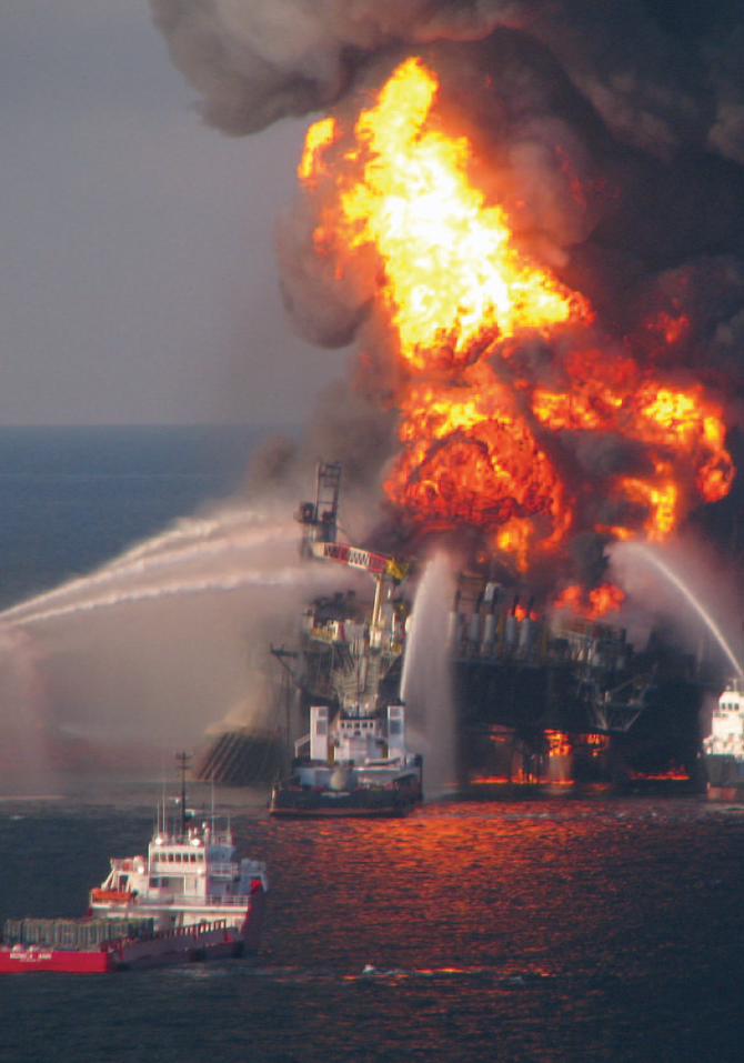
“But, who cares, it’s done, end of story, [we] will probably be fine and we’ll get a good cement job.”
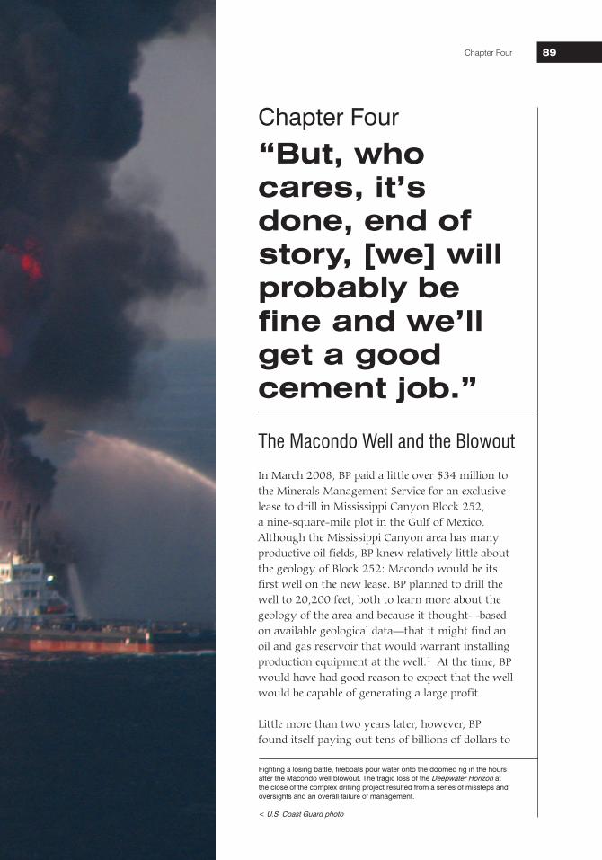
Fighting a losing battle, fireboats pour water onto the doomed rig in the hours after the Macondo well blowout. The tragic loss of the Deepwater Horizon at the close of the complex drilling project resulted from a series of missteps and oversights and an overall failure of management. < U.S. Coast Guard photo
National Commission on the BP Deepwater Horizon Oil Spill and Offshore Drilling90
contain a blowout at the Macondo well, mitigate the damage resulting from the millions of gallons of oil flowing from that well into the Gulf of Mexico, and compensate the hundreds of thousands of individuals and businesses harmed by the spill. And that is likely just the beginning. BP, its partners (Anadarko and MOEX), and its key contractors (particularly Halliburton and Transocean) face potential liability for the billions more necessary to restore natural resources harmed by the spill.
The well blew out because a number of separate risk factors, oversights, and outright mistakes combined to overwhelm the safeguards meant to prevent just such an event from happening. But most of the mistakes and oversights at Macondo can be traced back to a single overarching failure—a failure of management. Better management by BP, Halliburton, and Transocean would almost certainly have prevented the blowout by improving the ability of individuals involved to identify the risks they faced, and to properly evaluate, communicate, and address them. A blowout in deepwater was not a statistical inevitability.
The Challenges of Deepwater Drilling at the Macondo Well
High Pressures and Risk of a Well BlowoutOil forms deep beneath the Earth’s surface when organic materials deposited in ancient sediments slowly transform in response to intense heat and pressure. Over the course of millions of years, these materials “cook” into liquid and gaseous hydrocarbons. The transformed materials can flow through porous mineral layers, and tend to migrate upward because they are lighter than other fluids in the pore spaces. If there is a path that leads to the surface, the hydrocarbons will emerge above ground in a seep or tar pit. If an impermeable layer instead blocks the way, the hydrocarbons can collect in porous rock beneath the impermeable layer. The business of drilling for oil consists of finding and tapping these “pay zones” of porous hydrocarbon-filled rock.
Pore Pressure and Fracture GradientPore pressure is the pressure exerted by fluids in the pore space of rock. If drillers do not balance pore pressure with pressure from drilling fluids, hydrocarbons can flow into the wellbore (the hole drilled by the rig, including the casing) and unprotected sections of the well can collapse. The pore-pressure gradient, expressed as an equivalent mud weight, is a curve that shows the increase of pore pressure in a well by depth.
Fracture pressure is the pressure at which the geologic formation is not strong enough to withstand the pressure of the drilling fluids in a well and hence will fracture. When fracture occurs, drilling fluids flow out of the wellbore into the formation instead of circulating back to the surface. This causes what is known as “lost returns” or “lost circulation.” The fracture gradient, expressed as an equivalent mud weight, is a curve that shows the fracture pressure of rocks in a well by depth.
National Commission on the BP Deepwater Horizon Oil Spill and Offshore Drilling Chapter Four 9191
The weight of the rocks above a pay zone can generate tremendous pressure on the hydrocarbons. Typically, the deeper the well, the higher the pressure—and the higher the pressure, the greater the challenges in safely tapping those hydrocarbons. The first oil wells were drilled on land and involved relatively low-pressure oil reservoirs. As oil companies drilled farther offshore, they encountered large hydrocarbon deposits, often in more porous and permeable geologic formations, and, like at the Macondo well, at ever-higher pressures.
The principal challenge in deepwater drilling is to drill a path to the hydrocarbon-filled pay zone in a manner that simultaneously controls these enormous pressures and avoids fracturing the geologic formation in which the reservoir is found. It is a delicate balance. The drillers must balance the reservoir pressure (pore pressure) pushing hydrocarbons into the well with counter-pressure from inside the wellbore. If too much counter-pressure is used, the formation can be fractured. But if too little counter-pressure is used, the result can be an uncontrolled intrusion of hydrocarbons into the well, and a discharge from the well itself as the oil and gas rush up and out of the well. An uncontrolled discharge is known as a blowout.
Drill Pipe, Mud, Casing, Cement, and Well ControlThose drilling in deepwater, just like those drilling on land, use drill pipe, casing, mud, and cement in a series of carefully calibrated steps to control pressure while drilling thousands of feet below the seafloor to reach the pay zone. Drilling mud, which is used to lubricate and cool the drill bit during drilling, plays a critical role in controlling the hydrocarbon pressure in a well. The weight of the column of mud in a well exerts pressure that counterbalances the pressure in the hydrocarbon formation. If the mud weight is too low, fluids such as oil and gas can enter the well, causing what is known as a “kick.” But if the mud weight is too high, it can fracture the surrounding rock, potentially leading to “lost returns”—leakage of the mud into the formation. The rig crew therefore monitors and adjusts the weight (density) of the drilling mud as the well is being drilled—one of many sensitive, technical tasks requiring special equipment and the interpretation of data from difficult drilling environments.
Drilling TerminologyDrilling through the seafloor does not differ fundamentally from drilling on land. The crews on any drilling rig use rotary drill bits that they lubricate and cool with drilling mud—an ordinary name for what is today a sophisticated blend of synthetic fluids, polymers, and weighting agents that often costs over $100 per barrel. The rig crews pump the mud down through a drill pipe that connects with and turns the bit. The mud flows out holes in the bit and then circulates back to the rig through the space between the drill pipe and the sides of the well (the annulus), carrying to the surface bits of rock called cuttings that the drill bit has removed from the bottom of the well. When the mud returns to the rig at the surface, the cuttings are sieved out and the mud is sent back down the drill string. The mud thus travels in a closed loop.
As the well deepens, the crew lines its walls with a series of steel tubes called casing. The casing creates a foundation for continued drilling by reinforcing upper portions of the hole as drilling progresses. After installing a casing string, the crews drill farther, sending each successive string of casing down through the prior ones, so the well’s diameter becomes progressively smaller as it gets deeper. A completed deepwater well typically telescopes down from a starting casing diameter of three feet or more at the wellhead to a diameter of 10 inches or less at the bottom.
National Commission on the BP Deepwater Horizon Oil Spill and Offshore Drilling92
Casing strings, which are a series of steel tubes installed to line the well as the drilling progresses, also help to control pressures. First, they protect more fragile sections of the well structure outside the casing from the pressure of the mud inside. Second, they prevent high-pressure fluids (like hydrocarbons) outside the casing from entering the wellbore and flowing up the well. To secure the casing, crews pump in cement to seal the space between the casing and the wellbore. If a completed well can yield economically valuable oil and gas, the crews can initiate production by punching holes through the casing and surrounding cement to allow hydrocarbons to flow into the well.
Designed and used properly, drilling mud, cement, and casing work together to enable the crew to control wellbore pressure. If they fail, the crew can, in an emergency, close powerful blowout-preventer valves that should seal off the well at the wellhead.
Deepwater Horizon Arrives and Resumes Drilling the Well After purchasing the rights to drill in Block 252, BP became the legal “operator” for any activities on that block. But BP neither owned the rigs, nor operated them in the normal sense of the word. Rather, the company’s Houston-based engineering team designed the well and specified in detail how it was to be drilled. A team of specialized contractors would then do the physical work of actually drilling the well—a common industry practice. Transocean, a leading owner of deepwater drilling rigs, would provide BP with a rig and the crew to run it. Two BP “Well Site Leaders” (the “company men”) would be on the rig at all times to direct the crew and contractors and their work, and would maintain regular contact with the BP engineers on shore.
BP actually used two Transocean rigs to drill the Macondo well. The Marianas began work in October 2009 and drilled for 34 days, reaching a depth of 9,090 feet, before it had to stop drilling and move off-site to avoid Hurricane Ida. As described in Chapter 1, the storm nevertheless damaged the rig badly enough that BP called in the Deepwater Horizon to take over.
While the Marianas had been anchored in place with huge mooring chains, the Deepwater Horizon was a dynamically positioned mobile offshore drilling unit (MODU).2 It relied on thrusters and satellite-positioning technology to stay in place over the well. Once the rig arrived on January 31, 2010, and began drilling operations, Transocean’s Offshore Installation Manager Jimmy Harrell took over responsibility as the top Transocean employee on the rig.
When the Deepwater Horizon arrived, its first task was to lower its giant blowout preventer (BOP) onto the wellhead that the Marianas had left behind. The BOP is a stack of enormous valves that rig crews use both as a drilling tool and as an emergency safety device. Once it is put in place, everything needed in the well—drilling pipe, bits, casing, and mud—passes through the BOP. Every drilling rig has its own BOP, which its crew must test before and during drilling operations. After a week of surface testing, the Deepwater
National Commission on the BP Deepwater Horizon Oil Spill and Offshore Drilling Chapter Four 9393
Horizon rig crew lowered the 400-ton device down through a mile of seawater and used a remotely operated vehicle (ROV) to guide it so that it could be latched onto the wellhead below.
The Deepwater Horizon’s blowout preventer had several features that could be used to seal the well. The top two were large, donut-shaped rubber elements called “annular preventers” that encircled drill pipe or casing inside the BOP. When squeezed shut, they sealed off the annular space around the drill pipe. The BOP also contained five sets of metal rams. The “blind shear ram” was designed to cut through drill pipe inside the BOP to seal off the well in emergency situations. It could be activated manually by drillers on the rig, by an ROV, or by an automated emergency “deadman system.” A casing shear ram was designed to cut through casing; and three sets of pipe rams were in place to close off the space around the drill pipe.
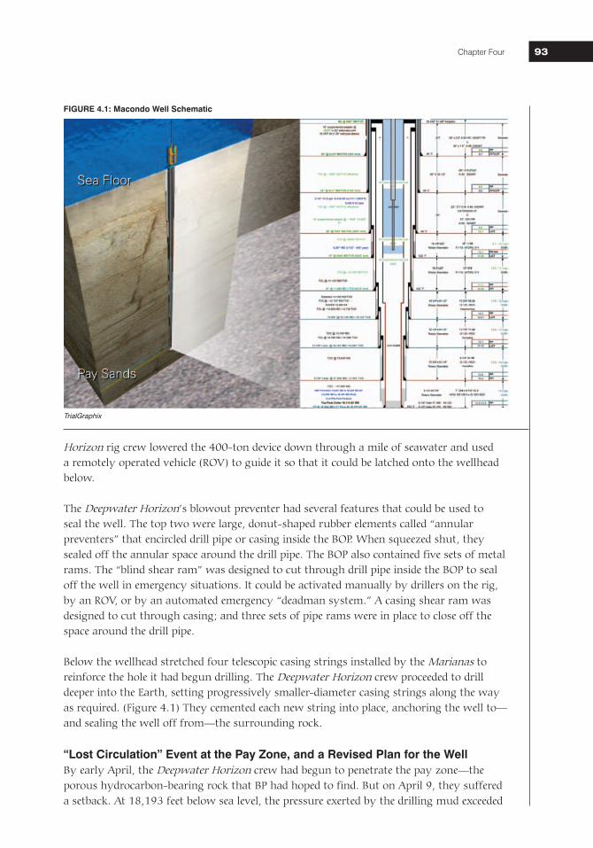
Below the wellhead stretched four telescopic casing strings installed by the Marianas to reinforce the hole it had begun drilling. The Deepwater Horizon crew proceeded to drill deeper into the Earth, setting progressively smaller-diameter casing strings along the way as required. (Figure 4.1) They cemented each new string into place, anchoring the well to—and sealing the well off from—the surrounding rock.
“Lost Circulation” Event at the Pay Zone, and a Revised Plan for the WellBy early April, the Deepwater Horizon crew had begun to penetrate the pay zone—the porous hydrocarbon-bearing rock that BP had hoped to find. But on April 9, they suffered a setback. At 18,193 feet below sea level, the pressure exerted by the drilling mud exceeded
FIGURE 4.1: Macondo Well Schematic
TrialGraphix
National Commission on the BP Deepwater Horizon Oil Spill and Offshore Drilling94
the strength of the formation. Mud began flowing into cracks in the formation instead of returning to the rig. The rig had to stop drilling until the crew could seal the fracture and restore mud circulation.3
Lost circulation events are a fact of life in the oil business. The crew responded with a standard industry tactic. They pumped 172 barrels of thick, viscous fluid known as a “lost circulation pill” down the drill string, hoping it would plug the fractures in the formation.4 The approach worked, but BP’s on-shore engineering team realized the situation had become delicate. They had to maintain the weight of the mud in the wellbore at approximately 14.0 pounds per gallon (ppg) in order to balance the pressure exerted by hydrocarbons in the pay zone.5 But drilling deeper would exert even more pressure on the formation, pressure that the BP team measured in terms of equivalent circulating density (ECD). The engineers calculated that drilling with 14.0 ppg mud in the wellbore would yield an ECD of nearly 14.5 ppg—enough of an increase that they risked further fracturing of the rock and more lost returns.
The engineers concluded they had “run out of drilling margin”: the well would have to stop short of its original objective of 20,200 feet.6 After cautiously drilling to a total depth of 18,360 feet, BP informed its lease partners Anadarko and MOEX that “well integrity and safety” issues required the rig to stop drilling further.7
At that point, Macondo was stable. Because the column of drilling mud in the wellbore was heavy enough to balance the hydrocarbon pressure, BP and its contractors, including Transocean, were able to spend the next five days8 between April 11 and 15 “logging” the open hole with sophisticated instruments. Based on the logging data, BP concluded that it had drilled into a hydrocarbon reservoir of sufficient size (at least 50 million barrels9) and pressure that it was economically worthwhile to install a final “production casing” string that BP would eventually use to recover the oil and gas.
Preparing the Well for Subsequent Production
The engineers recognized that the lost circulation problems and delicacy of the rock formation at the bottom of the well would make it challenging to install the production casing.10 After the rig crew lowered the casing into its final position, Halliburton would cement it into place. Halliburton would pump a specialized cement blend down the inside of the casing string; when it reached the end of the casing, cement would flow out the bottom and up into the annular space between the casing and the sides of the open hole. Once cured, the cement would bond to the formation and the casing and—if all went
Equivalent Circulating Density (ECD)A column of fluid will exert an amount of pressure on its surroundings that can be calculated if one knows the height of the column and the density of the fluid. If one pumps the fluid to make it circulate through the column, it will exert even more pressure. Equivalent circulating density or ECD is used to describe the total effective pressure that a column of drilling mud exerts on a formation as it is circulated through the drill string and back up the wellbore. To pump a given fluid faster or through narrower restrictions, it has to be pumped at greater pressure, and this, in turn, increases the ECD.
National Commission on the BP Deepwater Horizon Oil Spill and Offshore Drilling Chapter Four 9595
well—seal off the annular space. BP and Halliburton had cemented the previous casing strings at Macondo, and this cement job would be particularly important. The first attempt at cementing any casing string is commonly called the primary cement job. For a primary cement job to be successful, it must seal off, or “isolate,” the hydrocarbon-bearing zone from the annular space around the casing and from the inside of the casing itself.
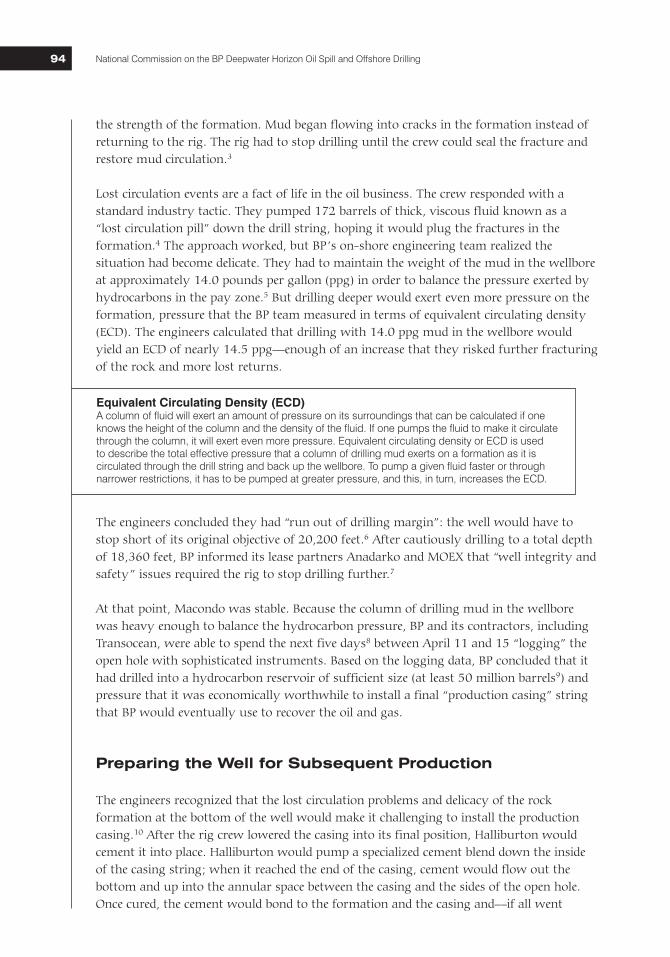
The Engineers Select a “Long String” CasingBP’s design team originally had planned to use a “long string” production casing—a single continuous wall of steel between the wellhead on the seafloor, and the oil and gas zone at the bottom of the well. But after the lost circulation event, they were forced to reconsider. As another option, they evaluated a “liner”—a shorter string of casing hung lower in the well and anchored to the next higher string. (Figure 4.2) A liner would result in a more complex—and theoretically more leak-prone—system over the life of the well. But it would be easier to cement into place at Macondo. On April 14 and 15, BP’s engineers, working with a Halliburton engineer, used sophisticated computer programs to model the likely outcome of the cementing process. When early results suggested the long string could not be cemented reliably, BP’s
FIGURE 4.2: “Long String” vs. “Liner”
Two options for the Macondo production casing.
TrialGraphix
National Commission on the BP Deepwater Horizon Oil Spill and Offshore Drilling96
design team switched to a liner. But that shift met resistance within BP.11 The engineers were encouraged to engage an in-house BP cementing expert to review Halliburton’s recommendations. That BP expert determined that certain inputs should be corrected. Calculations with the new inputs showed that a long string could be cemented properly. The BP engineers accordingly decided that installing a long string was “again the primary option.”12
Centralizers and the Risk of ChannelingInstalling the agreed-upon casing was a major job. Even moving at top speed, the crew on the Deepwater Horizon needed more than 18 hours just to lower a tool, such as a drill bit, from the rig floor to the bottom of the well, 18,000 feet below sea level. Assembling the production casing section-by-section and lowering the lengthening string down into the well below would require roughly 37 hours.13
As the crew gradually assembled and lowered the casing, they paused several times to install centralizers (Figure 4.3) at predetermined points along the casing string. Centralizers are critical components in ensuring a good cement job. When a casing string hangs in the center of the wellbore, cement pumped down the casing will flow evenly back up the annulus, displacing any mud and debris that were previously in that space and leaving a clean column of cement. If the casing is not centered, the cement will flow preferentially up the path of least resistance—the larger spaces in the annulus—and slowly or not at all in the narrower annular space. That can leave behind channels of drilling mud that can severely compromise a primary cement job by creating paths and gaps through which pressurized hydrocarbons can flow.
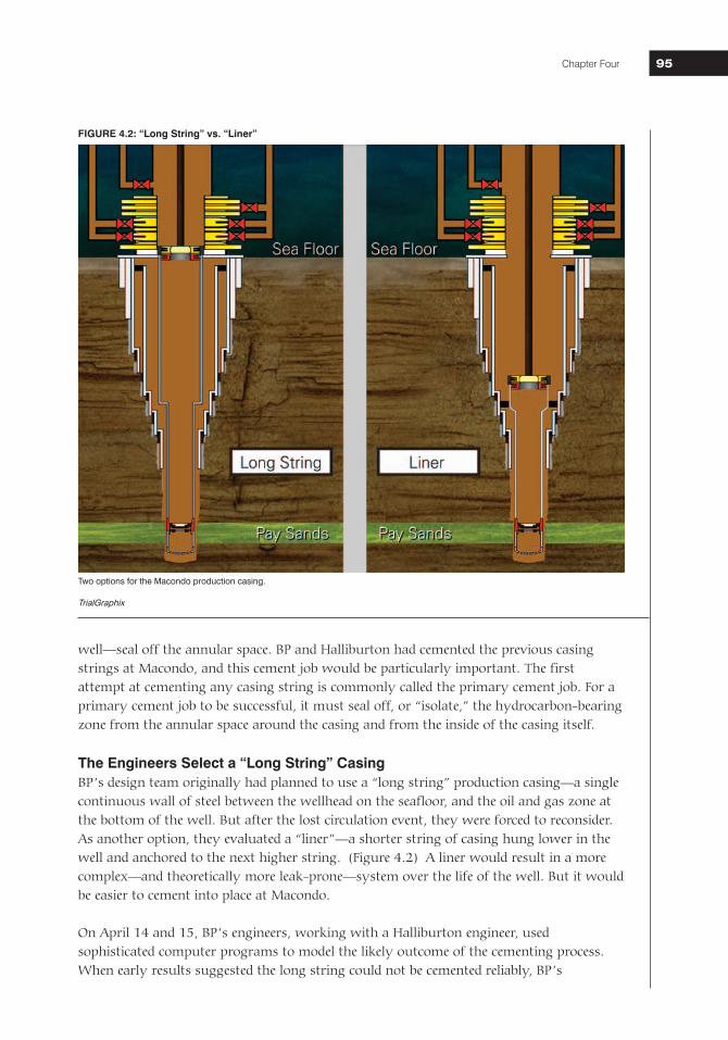
BP’s original designs had called for 16 or more centralizers to be placed along the long string.14 But on April 1, team member Brian Morel learned that BP’s supplier (Weatherford) had in stock only six “subs”15—centralizers designed to screw securely into
place between sections of casing. The alternative was to use “slip-on” centralizers—devices that slide onto the exterior of a piece of casing where they are normally secured in place by mechanical “stop collars” on either side. These collars can either be welded directly to the centralizers or supplied as separate pieces. The BP team—and Wells Team Leader John Guide in particular—distrusted slip-on centralizers with separate stop collars because the pieces can slide out of position or, worse, catch on other equipment as the casing is lowered.16
Shortly after the BP team decided on the long string, Halliburton engineer Jesse Gagliano ran computer simulations using proprietary software called OptiCem, in part to predict whether mud channeling would occur. OptiCem calculates the likely outcome of a cement job based on a number of variables, including the geometry of the wellbore and casing, the size and location of centralizers, the rate at which cement will be pumped, and the relative weight and viscosity of the cement
FIGURE 4.3: Centralizer Sub
Centralizer “subs” screw into place between sections of casing.
Weatherford
National Commission on the BP Deepwater Horizon Oil Spill and Offshore Drilling Chapter Four 9797
compared to the mud it displaces. Gagliano’s calculations suggested that the Macondo production casing would need more than six centralizers to avoid channeling.
Gagliano told BP engineers Mark Hafle and Brett Cocales about the problem on the afternoon of April 15.17 With de facto leader John Guide out of the office, Gregory Walz, the BP Drilling Engineering Team Leader, obtained permission from senior manager David Sims to order 15 additional slip-on centralizers—the most BP could transport immediately in a helicopter. That evening, Gagliano reran his simulations and found that channeling due to gas flow would be less severe with 21 centralizers in place. Late that night, Walz sent an e-mail to Guide explaining that he and Sims felt that BP needed to “honor the [OptiCem] modeling to be consistent with our previous decisions to go with the long string.”18
When Guide learned the next day of the decision to add more centralizers, he initially deferred, but then challenged the decision. Walz had earlier assured Guide that the 15 additional centralizers would be custom-designed one-piece units that BP had used on a prior well and would limit the potential for centralizer “hang up.”19 But when the centralizers arrived, BP engineer Brian Morel, who happened to be out on the rig, reported that the centralizers were of conventional design with separate stop collars. Morel e-mailed BP drilling engineer Brett Cocales to question the need for additional centralizers.20 Cocales responded that the team would “probably be fine” even without the additional centralizers and that “Guide is right on the risk/reward equation.”21
Guide pointed out to Walz that the new centralizers were not custom-made as specified.22 “Also,” he noted, “it will take 10 hrs to install them.” He complained that the “last minute addition” of centralizers would add 45 pieces of equipment to the casing that could come off during installation, and concluded by saying that he was “very concerned.” In the end, Guide’s view prevailed; BP installed only the six centralizer subs on the Macondo production casing.
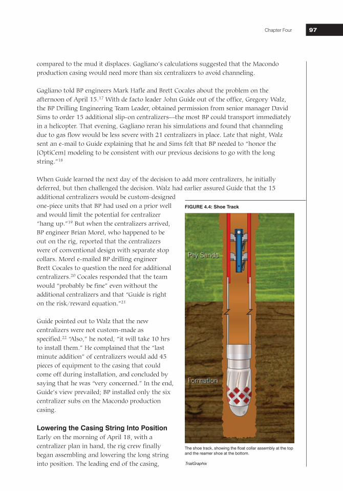
Lowering the Casing String Into PositionEarly on the morning of April 18, with a centralizer plan in hand, the rig crew finally began assembling and lowering the long string into position. The leading end of the casing,
The shoe track, showing the float collar assembly at the top and the reamer shoe at the bottom.
TrialGraphix
FIGURE 4.4: Shoe Track
National Commission on the BP Deepwater Horizon Oil Spill and Offshore Drilling98
the “shoe track,” began with a “reamer shoe”—a bullet-shaped piece of metal with three holes designed to help guide the casing down the hole. (Figure 4.4) The reamer shoe was followed by 180 feet of seven-inch-diameter steel casing. Then came a Weatherford-manufactured “float collar,” a simple arrangement of two flapper (float) valves, spaced one after the other, held open by a short “auto-fill tube” through which the mud in the well could flow. As the long string was lowered down the wellbore, the mud passed through the holes in the reamer shoe and auto-fill tube that propped open the float valves, giving it a clear flow path upward.
Preparation for Cementing—and Unexpected Pressure Anomalies in the WellThe long string was installed in its final position early on the afternoon of April 19. With the top end of the string seated in the wellhead and its bottom end located just above the bottom of the wellbore, the crew’s next job was to prepare the float-valve system for cementing. During the cementing process, fluids pumped into the well should flow in a one-way path: down the center of the last casing string, out the bottom, and up the annulus (between the exterior of the steel casing and the surrounding rock formations). To ensure unidirectional flow, the crew needed to push the auto-fill tube downward, so it would no longer prop open the float valves. With the tube out of the way, the flapper valves would spring shut and convert from two-way valves into one-way valves that would allow mud and cement to flow down the casing into the shoe track, but prevent any fluid from reversing direction and coming back up the casing. Once the float valves had converted, Halliburton could pump cement down through the casing and up around the annulus; the valves would keep cement from flowing back up the casing once the crew stopped pumping.
To convert the float valves, that evening the crew began pumping mud down through the casing. Based on Weatherford’s specifications, the valves should convert once the rate of flow though holes in the auto-fill tube had reached roughly 6 barrels per minute (bpm), causing a differential pressure on the tube of approximately 600 pounds per square inch (psi).23 But the crew hit a stumbling block. They pumped fluids into the well, eventually pressuring up to 1,800 psi, but could not establish flow.
Well Site Leader Bob Kaluza and BP engineer Morel24 called Guide, their supervisor on shore. In consultation with Guide and Weatherford staff, the rig team decided to increase the pump pressure in discrete increments, hoping eventually to dislodge the auto-fill tube.25 On their ninth attempt, pump pressure peaked at 3,142 psi and then suddenly dropped as mud finally began to flow. Significantly, however, the pump rate of mud into the well and through the shoe track thereafter never exceeded approximately 4 bpm.26
BP’s team concluded that the float valves had converted, but noted another anomaly. The drilling-mud subcontractor, M-I SWACO, had predicted that it would take a pressure of 570 psi to circulate mud after converting the float valves.27 Instead, the rig crew reported that circulation pressure was much lower: only 340 psi. BP’s Well Site Leader Bob Kaluza expressed concern about low circulating pressure.28 He and the Transocean crew switched circulating pumps to see if that made a difference, and eventually concluded that the pressure gauge they had been relying on was broken.29 Believing they had converted the
National Commission on the BP Deepwater Horizon Oil Spill and Offshore Drilling Chapter Four 9999
float valves and reestablished mud circulation in the well, BP was ready at last to pump cement down the production casing and complete the primary cement job.
The Inherently Uncertain Cementing ProcessCementing an oil well is an inherently uncertain process. To establish isolation across a hydrocarbon zone at the bottom of a well, engineers must send a slug of cement down the inside of the well. They then pump mud in after it to push the cement down until it “turns the corner” at the bottom of the well and flows up into the annular space. If done properly, the slug of cement will create a long and continuous seal around the production casing, and will fill the shoe track in the bottom of the final casing string. But things can go wrong even under optimal conditions. If the cement is pumped too far or not far enough, it may not isolate the hydrocarbon zones. If oil-based drilling mud contaminates the water-based cement as the cement flows down the well, the cement can set slowly or not at all. And, as previously noted, the cement can “channel,” filling the annulus unevenly and allowing hydrocarbons to bypass cement in the annular space. Given the variety of things that can go wrong with a cement job, it is hardly surprising that a 2007 MMS study identified cementing problems as one of the “most significant factors” leading to blowouts between 1992 and 2006.30
Even following best practices, a cement crew can never be certain how a cement job at the bottom of the well is proceeding as it is pumped. Cement does its work literally miles away from the rig floor, and the crew has no direct way to see where it is, whether it is contaminated, or whether it has sealed off the well. To gauge progress, the crew must instead rely on subtle, indirect indicators like pressure and volume: they know how much cement and mud they have sent down the well and how hard the pumps are working to push it. The crew can use these readings to check whether each barrel of cement pumped into the well displaces an equal volume of drilling mud—producing “full returns.” They can also check for pressure spikes to confirm that “wiper plugs” (used to separate the cement from the surrounding drilling mud) have landed on time as expected at the bottom of the well. And they can look for “lift pressure”—a steady increase in pump pressure signifying that the cement has turned the corner at the bottom of the well and is being pushed up into the annular space against gravity.
While they suggest generally that the job has gone as planned, these indicators say little specific about the location and quality of the cement at the bottom of the well. None of them can take the place of pressure testing and cement evaluation logging (see below).
The Cementing Design: Critical Decisions for a Fragile FormationIn the days leading up to the final cementing process, BP engineers focused heavily on the biggest challenge: the risk of fracturing the formation and losing returns. John Guide explained after the incident that losing returns “was the No. 1 risk.”31 He and the other BP engineers worried that if their cementing procedure placed too much pressure on the geologic formation below, it might trigger another lost-returns event similar to the one on April 9. In this case, critical cement—not mud—might flow into the formation and be lost, potentially leaving the annular space at the bottom of the well open to hydrocarbon flow.
National Commission on the BP Deepwater Horizon Oil Spill and Offshore Drilling100
The BP team’s concerns led them to place a number of significant constraints on Halliburton’s cementing design. The first compromise in BP’s plan was to limit the circulation of drilling mud through the wellbore before cementing. Optimally, mud in the wellbore would have been circulated “bottoms up”—meaning the rig crew would have pumped enough mud down the wellbore to bring mud originally at the bottom of the well all the way back up to the rig. There are at least two benefits to bottoms up circulation. Such extensive circulation cleans the wellbore and reduces the likelihood of channeling. And circulating bottoms up allows technicians on the rig to examine mud from the bottom of the well for hydrocarbon content before cementing. But the BP engineers feared that the longer the rig crew circulated mud through the casing before cementing, the greater the risk of another lost-returns event. Accordingly, BP circulated approximately 350 barrels of mud before cementing, rather than the 2,760 barrels needed to do a full bottoms up circulation.32
BP compromised again by deciding to pump cement down the well at the relatively low rate of 4 barrels or less per minute.33 Higher flow rates tend to increase the efficiency with which cement displaces mud from the annular space. But the increased pump pressure required to move the cement quickly would mean more pressure on the formation (ECD) and an increased risk of lost returns. BP decided to reduce the risk of lost returns in exchange for a less-than-optimal rate of cement flow.
BP made a third compromise by limiting the volume of cement that Halliburton would pump down the well. Pumping more cement is a standard industry practice to insure against uncertain cementing conditions: more cement means less risk of contamination and less risk that the cement job will be compromised by slight errors in placement. But more cement at Macondo would mean a higher cement column in the annulus, which in turn would exert more pressure on the fragile formation below. Accordingly, BP determined that the annular cement column should extend only 500 feet above the uppermost hydrocarbon-bearing zone (and 800 feet above the main hydrocarbon zones), and that this would be sufficient to fulfill MMS regulations of “500 feet above the uppermost hydrocarbon-bearing zone.”34 However, it did not satisfy BP’s own internal guidelines, which specify that the top of the annular cement should be 1,000 feet above the uppermost hydrocarbon zone.35 As designed, BP would have Halliburton pump a total of approximately 60 barrels of cement down the well—a volume that its own engineers recognized would provide little margin for error.36
Finally, in close consultation with Halliburton, BP chose to use “nitrogen foam cement”—a cement formula that has been leavened with tiny bubbles of nitrogen gas, injected into the cement slurry just before it goes down the well. This formula was chosen to lighten the resulting slurry from approximately 16.7 ppg to 14.5 ppg—thereby reducing the pressure the cement would exert on the fragile formation. The bubbles, in theory, would also help to balance the pore pressure in the formation and clear the annular space of mud as the cement flowed upward. Halliburton is an industry leader in foam cementing, but BP appears to have had little experience with foam technology for cementing production casing in the Gulf of Mexico.37
National Commission on the BP Deepwater Horizon Oil Spill and Offshore Drilling Chapter Four 101101
The Cement Slurry: Laboratory AnalysesA cement slurry must be tested before it is used in a cement job. Because the pressure and temperature at the bottom of a well can significantly alter the strength and curing rate of a given cement slurry—and because storing cement on a rig can alter its chemical composition over time—companies like Halliburton normally fly cement samples from the rig back to a laboratory shortly before pumping a job to make sure the cement will work under the conditions in the well. The laboratory conducts a number of tests to evaluate the slurry’s viscosity and flow characteristics, the rate at which it will cure, and its eventual compressive strength.
When testing a slurry that will be foamed with nitrogen, the lab also evaluates the stability of the cement that results. A stable foam slurry will retain its bubbles and overall density long enough to allow the cement to cure. The result is hardened cement that has tiny, evenly dispersed, and unconnected nitrogen bubbles throughout. If the foam does not remain stable up until the time the cement cures, the small nitrogen bubbles may coalesce into larger ones, rendering the hardened cement porous and permeable.38 If the instability is particularly severe, the nitrogen can “break out” of the cement, with unpredictable consequences.
On February 10, soon after the Deepwater Horizon began work on the well, Jesse Gagliano asked Halliburton laboratory personnel to run a series of “pilot tests” on the cement blend stored on the Deepwater Horizon that Halliburton planned to use at Macondo.39 They tested the slurry40 and reported the results to Gagliano. He sent the laboratory report to BP on March 8 as an attachment to an e-mail in which he discussed his recommended plan for cementing an earlier Macondo casing string.41
The reported data that Gagliano sent to BP on March 8 included the results of a single foam stability test. To the trained eye, that test showed that the February foam slurry design was unstable. Gagliano did not comment on the evidence of the cement slurry’s instability, and there is no evidence that BP examined the foam stability data in the report at all.
Documents identified after the blowout reveal that Halliburton personnel had also conducted another foam stability test earlier in February. The earlier test had been conducted under slightly different conditions than the later one and had failed more severely.42 It appears that Halliburton never reported the results of the earlier February test to BP.
Halliburton conducted another round of tests in mid-April, just before pumping the final cement job. By then, the BP team had given Halliburton more accurate information about the temperatures and pressures at the bottom of the Macondo well, and Halliburton had progressed further with its cementing plan. Using this information, the laboratory personnel conducted several tests, including a foam stability test, starting on approximately April 13. The first test Halliburton conducted showed once again that the cement slurry would be unstable.43 The Commission does not believe that Halliburton ever reported this information to BP. Instead, it appears that Halliburton personnel subsequently ran a second foam stability test, this time doubling the pre-test “conditioning time” to three hours.44
National Commission on the BP Deepwater Horizon Oil Spill and Offshore Drilling102
The evidence suggests that Halliburton began the second test at approximately 2:00 a.m. on April 18.45 That test would normally take 48 hours. Halliburton finished pumping the cement job just before 48 hours would have elapsed.46 Although the second test at least arguably suggests the foam cement design used at Macondo would be stable, it is unclear whether Halliburton had results from that test in hand before it pumped the job. Halliburton did not send the results of the final test to BP until April 26, six days after the blowout.47
Evaluating the Cementing JobTransocean’s rig crew and Halliburton’s cementers finished pumping the primary cement job at 12:40 a.m. on April 20.48 Once the pumps were off, a BP representative and Vincent Tabler of Halliburton performed a check to see whether the float valves were closed and holding. They opened a valve at the cementing unit to see whether any fluid flowed from the well. If more fluid came back than expected, that would indicate that cement was migrating back up into the casing and pushing the fluids above it out of the top of the well. Models had predicted 5 barrels of flow back. According to Brian Morel, the two men observed 5.5 barrels of flow, tapering off to a “finger tip trickle.”49 According to Morel, 5.5 barrels of flow-back volume was within the acceptable margin for error.50 Tabler testified that they watched flow “until it was probably what we call a pencil stream,” which stopped, started up again, and then stopped altogether.51 While it is not clear how long the two men actually watched for potential flow, they eventually concluded the float valves were holding.
With no lost returns, BP and Halliburton declared the job a success. Nathaniel Chaisson, one of Halliburton’s crew on the rig, sent an e-mail to Jesse Gagliano at 5:45 a.m. saying, “We have completed the job and it went well.”52 He attached a detailed report stating that the job had been “pumped as planned” and that he had seen full returns throughout the process.53 And just before leaving the rig, Morel e-mailed the rest of the BP team to say “the Halliburton cement team . . . did a great job.”54
At the 7:30 a.m. morning meeting with contractors on the rig, the BP team concluded the cement job went well enough to send home a team of technicians from Schlumberger who had been standing by on the rig for at least one day already55 waiting to perform a suite of cement evaluation tests on the primary cement job, including cement bond logs.56 The BP team relied on a “decision tree” that Guide and BP engineers had prepared beforehand. The
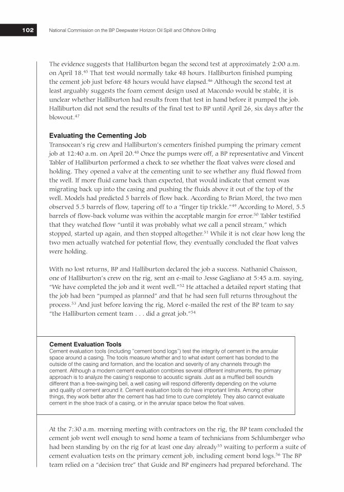
Cement Evaluation ToolsCement evaluation tools (including “cement bond logs”) test the integrity of cement in the annular space around a casing. The tools measure whether and to what extent cement has bonded to the outside of the casing and formation, and the location and severity of any channels through the cement. Although a modern cement evaluation combines several different instruments, the primary approach is to analyze the casing’s response to acoustic signals. Just as a muffled bell sounds different than a free-swinging bell, a well casing will respond differently depending on the volume and quality of cement around it. Cement evaluation tools do have important limits. Among other things, they work better after the cement has had time to cure completely. They also cannot evaluate cement in the shoe track of a casing, or in the annular space below the float valves.
National Commission on the BP Deepwater Horizon Oil Spill and Offshore Drilling Chapter Four 103103
primary criterion BP appears to have used to determine whether to perform the cement evaluation test was whether there were “[l]osses while cementing [the] long string.”57 Having seen no lost returns during the cement job, BP sent the Schlumberger team home and moved on to prepare the well for temporary abandonment.
Temporary Abandonment and Preparing to Move On to the Next Job
Once BP decided to send the Schlumberger team home, Deepwater Horizon’s crew began the final phase of its work. Drilling the Macondo well had required a giant offshore rig of Deepwater Horizon’s capabilities. By contrast, BP, like most operators, would give the job of “completing” the well to a smaller (and less costly) rig, which would install hydrocarbon-collection and -production equipment. To make way for the new rig, the Deepwater Horizon would have to remove its riser* and blowout preventer from the wellhead—and before it could do those things, the crew had to secure the well through a process called “temporary abandonment.”
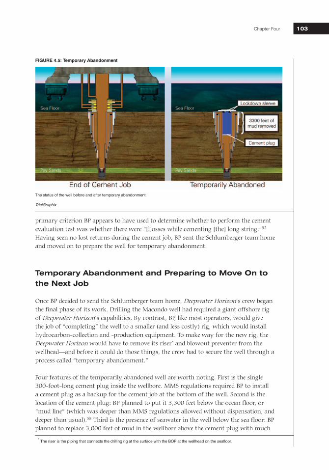
Four features of the temporarily abandoned well are worth noting. First is the single 300-foot-long cement plug inside the wellbore. MMS regulations required BP to install a cement plug as a backup for the cement job at the bottom of the well. Second is the location of the cement plug: BP planned to put it 3,300 feet below the ocean floor, or “mud line” (which was deeper than MMS regulations allowed without dispensation, and deeper than usual).58 Third is the presence of seawater in the well below the sea floor: BP planned to replace 3,000 feet of mud in the wellbore above the cement plug with much
FIGURE 4.5: Temporary Abandonment
The status of the well before and after temporary abandonment.
TrialGraphix
* The riser is the piping that connects the drilling rig at the surface with the BOP at the wellhead on the seafloor.

National Commission on the BP Deepwater Horizon Oil Spill and Offshore Drilling104
lighter seawater (seawater weighs roughly 8.6 ppg, while the mud in the wellbore weighed roughly 14.5 ppg). Fourth is the lockdown sleeve—a mechanical device that locks the long casing string to the wellhead to prevent it from lifting out of place during subsequent production operations. (Figure 4.5)
At 10:43 a.m., Morel e-mailed an “Ops Note” to the rest of the Macondo team listing the temporary abandonment procedures for the well.59 It was the first time the BP Well Site Leaders on the rig had seen the procedures they would use that day. BP first shared the procedures with the rig crew at the 11 a.m. pre-tour meeting that morning.60 The basic sequence was as follows:
1. Perform a positive-pressure test to test the integrity of the production casing;2. Run the drill pipe into the well to 8,367 feet (3,300 feet below the mud line);3. Displace 3,300 feet of mud in the well with seawater, lifting the mud above the BOP
and into the riser;4. Perform a negative-pressure test to assess the integrity of the well and bottom-hole
cement job to ensure outside fluids (such as hydrocarbons) are not leaking into the well;
5. Displace the mud in the riser with seawater;6. Set the surface cement plug at 8,367 feet; and7. Set the lockdown sleeve.61
The crew would never get through all of the steps in the procedure.
BP’s Macondo team had made numerous changes to the temporary abandonment procedures in the two weeks leading up to the April 20 “Ops Note.” For example, in its April 12 drilling plan, BP had planned (1) to set the lockdown sleeve before setting the surface cement plug and (2) to set the surface cement plug in seawater only 6,000 feet below sea level (as opposed to 8,367 feet). The April 12 plan did not include a negative-pressure test.62 On April 14, Morel sent an e-mail entitled “Forward Ops” setting forth a different procedure, which included a negative-pressure test but would require setting the surface cement plug in mud before displacement of the riser with seawater.63 On April 16, BP sent an Application for Permit to Modify to MMS describing a temporary abandonment procedure that was different from the procedure in either the April 12 drilling plan, the April 14 e-mail, or the April 20 “Ops Note.”64 There is no evidence that these changes went through any sort of formal risk assessment or management of change process.
Lockdown SleeveBefore the Macondo blowout, a lockdown sleeve was not generally considered a safety mechanism or barrier to flow prior to the production phase of the well. Drilling rigs did not generally set lockdown sleeves. Rather, completion or production rigs did so after the drilling phase. BP decided to have the Deepwater Horizon set the lockdown sleeve because the Horizon could do the job more quickly than the completion rig. Based on the Macondo event, and given early concerns that upward forces during the blowout had approached or exceeded the force needed to lift the production casing up out of its seat in the wellhead, the Commission believes operators should consider installing a lockdown sleeve or other device to lock the casing hanger in place as part of drilling operations (or, at the very least, at the outset of temporary abandonment).
National Commission on the BP Deepwater Horizon Oil Spill and Offshore Drilling Chapter Four 105105
Countdown to BlowoutThe first step in the temporary abandonment was to test well integrity: to make sure there were no leaks in the well.
The Positive-Pressure TestThe positive-pressure test evaluates, among other things, the ability of the casing in the well to hold in pressure. MMS regulations require a positive-pressure test prior to temporary abandonment.65 To perform the test at Macondo, the Deepwater Horizon’s crew first closed off the well below the BOP by shutting the blind shear ram (there was no drill pipe in the well at the time).66 Then, much like pumping air into a bike tire to check for leaks, the rig crew pumped fluids into the well (through pipes running from the rig to the BOP) to generate pressure and then checked to see if it would hold.
The crew started the positive-pressure test at noon.67 They pressured the well up to 250 psi for 5 minutes, and then pressured up to 2,500 psi and watched for 30 minutes. The pressure inside the well remained steady during both tests, showing there were no leaks in the production casing through which fluids could pass from inside the well to the outside. The drilling crew and BP’s Well Site Leader Bob Kaluza considered the test successful. Later in the afternoon, Kaluza showed visiting BP executive Pat O’Bryan the pressure chart from the test; O’Bryan remarked, “Things looked good with the positive test.”68
The Negative-Pressure Test: Unexpected Pressure Readings The negative-pressure test checks not only the integrity of the casing, like the positive-pressure test, but also the integrity of the bottomhole cement job. At the Macondo well, the negative-pressure test was the only test performed that would have checked the integrity of the bottomhole cement job.
Instead of pumping pressure into the wellbore to see if fluids leak out, the crew removes pressure from inside the well to see if fluids, such as hydrocarbons, leak in, past or through the bottomhole cement job. In so doing, the crew simulates the effect of removing the mud in the wellbore and the riser (and the pressure exerted by that mud) during temporary abandonment. If the casing and primary cement have been designed and installed properly, they will prevent hydrocarbons from intruding even when that “overbalancing” pressure is removed.69 First, the crew sets up the well to simulate the expected hydrostatic pressure exerted by the column of fluids on the bottom of the well in its abandoned state. Second, the crew bleeds off any pent-up pressure that remains in the well, taking it down to 0 psi. Third, the crew and Well Site Leaders watch to make sure that nothing flows up from and out of the well and that no pressure builds back up inside of the well. If there is no flow or pressure buildup, that means that the casing and primary cement have sealed the well off from external fluid pressure and flow. A negative-pressure test is successful if there is no flow out of the well for a sustained period and if there is no pressure build-up inside the well when it is closed at the surface.
To conduct a proper negative test at Macondo, BP would have to isolate the well from the effect of the 5,000-foot-plus column of drilling mud in the riser and a further 3,300-foot column of drilling mud below the seafloor. Those heavy columns of mud exerted much
National Commission on the BP Deepwater Horizon Oil Spill and Offshore Drilling106
more pressure on the well than the seawater that would replace them after temporary abandonment. Specifically, the pressure at the bottom of the well would be approximately 2,350 psi lower after temporary abandonment than before.70 Once this pressure was removed, the downward force of the column of fluids in the well would be less than the pressure of the hydrocarbons in the reservoir, so the well would be in what is called an “underbalanced” state. It was therefore critical to test and confirm the ability of the well (including the primary cement job) to withstand the underbalance. If the test showed that hydrocarbons would leak into the well once it was underbalanced, BP would need to diagnose and fix the problem (perhaps remediating the cement job) before moving on, a process that could take many days.
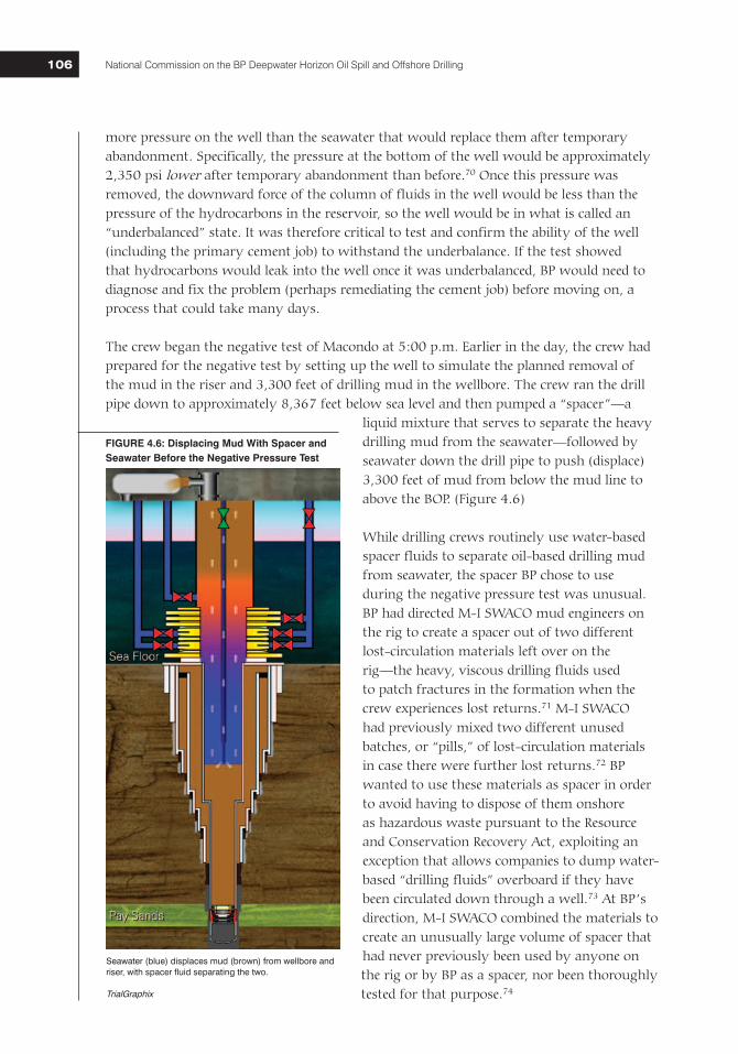
The crew began the negative test of Macondo at 5:00 p.m. Earlier in the day, the crew had prepared for the negative test by setting up the well to simulate the planned removal of the mud in the riser and 3,300 feet of drilling mud in the wellbore. The crew ran the drill pipe down to approximately 8,367 feet below sea level and then pumped a “spacer”—a
liquid mixture that serves to separate the heavy drilling mud from the seawater—followed by seawater down the drill pipe to push (displace) 3,300 feet of mud from below the mud line to above the BOP. (Figure 4.6)
While drilling crews routinely use water-based spacer fluids to separate oil-based drilling mud from seawater, the spacer BP chose to use during the negative pressure test was unusual. BP had directed M-I SWACO mud engineers on the rig to create a spacer out of two different lost-circulation materials left over on the rig—the heavy, viscous drilling fluids used to patch fractures in the formation when the crew experiences lost returns.71 M-I SWACO had previously mixed two different unused batches, or “pills,” of lost-circulation materials in case there were further lost returns.72 BP wanted to use these materials as spacer in order to avoid having to dispose of them onshore as hazardous waste pursuant to the Resource and Conservation Recovery Act, exploiting an exception that allows companies to dump water-based “drilling fluids” overboard if they have been circulated down through a well.73 At BP’s direction, M-I SWACO combined the materials to create an unusually large volume of spacer that had never previously been used by anyone on the rig or by BP as a spacer, nor been thoroughly tested for that purpose.74
Seawater (blue) displaces mud (brown) from wellbore and riser, with spacer fluid separating the two.
TrialGraphix
FIGURE 4.6: Displacing Mud With Spacer and Seawater Before the Negative Pressure Test
National Commission on the BP Deepwater Horizon Oil Spill and Offshore Drilling Chapter Four 107107
Once the crew had displaced the mud to above the BOP, they shut an annular preventer in the BOP, isolating the well from the downward pressure exerted by the heavy mud and spacer in the riser. The crew could now perform the negative-pressure test using the drill pipe: it would open the top of the drill pipe on the rig, bleed the drill pipe pressure to zero, and then watch for flow. The crew opened the drill pipe at the rig to bleed off any pressure that had built up in the well during the mud-displacement process. The crew tried to bleed the pressure down to zero, but could not get it below 266 psi. When the drill pipe was closed, the pressure jumped back up to 1,262 psi.
Around this time, the driller’s shack was growing crowded. The night crew was arriving in preparation for the 6:00 p.m. shift change, which meant that both toolpushers—Wyman Wheeler and Jason Anderson—and both Well Site Leaders—Bob Kaluza and Don Vidrine—were present. In addition, a group of visiting BP and Transocean executives entered as part of a rig tour escorted by Transocean Offshore Installation Manager Jimmy Harrell.75 It was apparent to at least one member of the tour that the crew was having a “little bit of a problem.”76
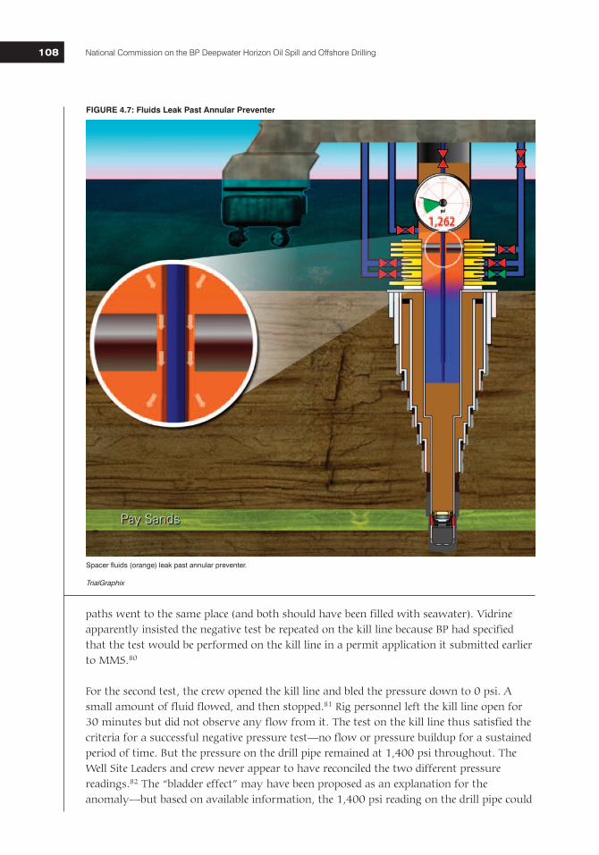
The crew had noticed that the fluid level inside the riser was dropping, suggesting that spacer was leaking down past the annular preventer, out of the riser, and into the well (Figure 4.7). Harrell, who stayed behind in the drill shack as the tour continued, ordered the annular preventer closed more tightly to stop the leak.77 Harrell then left the rig floor.
With that problem solved, the crew refilled the riser and once again opened up the drill pipe and attempted a second time to bleed the pressure down to 0 psi. This time, they were able to do so. But when they shut the drill pipe in again, the pressure built back up to at least 773 psi. The crew then attempted a third time to bleed off the pressure from the drill pipe, and was again able to get it down to 0 psi. When the crew shut the well back in, however, the pressure increased to 1,400 psi. At this point, the crew had bled the drill-pipe pressure down three times, but each time it had built back up. For a successful negative-pressure test, the pressure must remain at 0 psi when the pipe is closed after the pressure is bled off.
The Transocean crew and BP Well Site Leaders met on the rig floor to discuss the readings. In addition to Kaluza, Vidrine, and Anderson, Dewey Revette (Transocean’s on-duty driller) and BP Well Site Leader trainee Lee Lambert were there. According to post-incident statements from both Well Site Leaders, Anderson said that the 1,400 psi pressure on the drill pipe was being caused by a phenomenon called the “bladder effect.”78 According to Lambert, Anderson explained that heavy mud in the riser was exerting pressure on the annular preventer, which in turn transmitted pressure to the drill pipe. Lambert said that he did not recall anyone agreeing or disagreeing with Anderson’s explanation.79
According to Harrell, after a lengthy discussion, BP Well Site Leader Vidrine then insisted on running a second negative-pressure test, this time monitoring pressure and flow on the kill line rather than the drill pipe. (The kill line is one of three pipes, each approximately 3 inches in diameter, that run from the rig to the BOP to allow the crew to circulate fluids into and out of the well at the sea floor.) The pressure on the kill line during the negative-pressure test should have been identical to the pressure on the drill pipe, as both flow
National Commission on the BP Deepwater Horizon Oil Spill and Offshore Drilling108
paths went to the same place (and both should have been filled with seawater). Vidrine apparently insisted the negative test be repeated on the kill line because BP had specified that the test would be performed on the kill line in a permit application it submitted earlier to MMS.80
For the second test, the crew opened the kill line and bled the pressure down to 0 psi. A small amount of fluid flowed, and then stopped.81 Rig personnel left the kill line open for 30 minutes but did not observe any flow from it. The test on the kill line thus satisfied the criteria for a successful negative pressure test—no flow or pressure buildup for a sustained period of time. But the pressure on the drill pipe remained at 1,400 psi throughout. The Well Site Leaders and crew never appear to have reconciled the two different pressure readings.82 The “bladder effect” may have been proposed as an explanation for the anomaly—but based on available information, the 1,400 psi reading on the drill pipe could
Spacer fluids (orange) leak past annular preventer.
TrialGraphix
FIGURE 4.7: Fluids Leak Past Annular Preventer
National Commission on the BP Deepwater Horizon Oil Spill and Offshore Drilling Chapter Four 109109
only have been caused by a leak into the well. Nevertheless, at 8 p.m., BP Well Site Leaders, in consultation with the crew, made a key error and mistakenly concluded the second negative test procedure had confirmed the well’s integrity. They declared the test a success and moved on to the next step in temporary abandonment.
Displacing Mud from the Riser—and Mounting Signs of a Kick At 8:02 p.m., the crew opened the annular preventer and began displacing mud and spacer from the riser. Halliburton cementer Chris Haire went to the drill shack to check on the status of the upcoming surface cement plug job. Revette and Anderson told him the negative-pressure test had been successful and that Haire should prepare to set the surface cement plug.83
Revette sat down in his driller’s chair to monitor the well for kicks—any unplanned influxes of gas or fluids—and other anomalies. As gaseous hydrocarbons in a kick rise up the wellbore, they expand with ever-increasing speed—a barrel of natural gas at Macondo could expand over a hundredfold as it traveled the 5,000 feet between the wellhead and the rig above.84 And as the gas expands, it pushes mud upward faster and faster, reducing the pressure on the gas and increasing the speed of the kick—making it imperative that rig crews recognize and respond to a kick as early as possible.
The individuals responsible for detecting kicks on a rig include the driller, assistant drillers, and the mudlogger.85 Dewey Revette was the driller on duty at the time; the two assistant drillers on duty were Donald Clark and Stephen Curtis. Joseph Keith of Sperry Sun was the mudlogger.
These individuals look for kicks by monitoring real-time data displays in the driller’s shack, mudlogger’s shack, and elsewhere on the rig. They watch two primary parameters. The first, and most reliable when available, is the volume of mud in the active pits. The volume of mud sent from the active pits into the well should equal the volume of mud returning to the active pits from the well. An increase in volume is a powerful indicator that something is flowing into the well.
Second, under normal circumstances, the volume and rate of flow of fluids coming from the well should equal the volume and rate of flow of fluid pumped into the well. If flow out of the well is greater than flow into the well, it is a strong indicator that a kick may be under way.
In addition to these two primary parameters, the crew can perform visual “flow checks.” There were a number of cameras and stations on the Deepwater Horizon where the driller, mudlogger, and others could observe whether fluids were flowing from the well. When
Active Pit SystemRigs contain multiple mud pits. The Deepwater Horizon had 20 in all. Various fluids can be stored in these pits, including drilling mud. The active pit system is a subset of the mud pits that the driller selects for monitoring purposes.
National Commission on the BP Deepwater Horizon Oil Spill and Offshore Drilling110
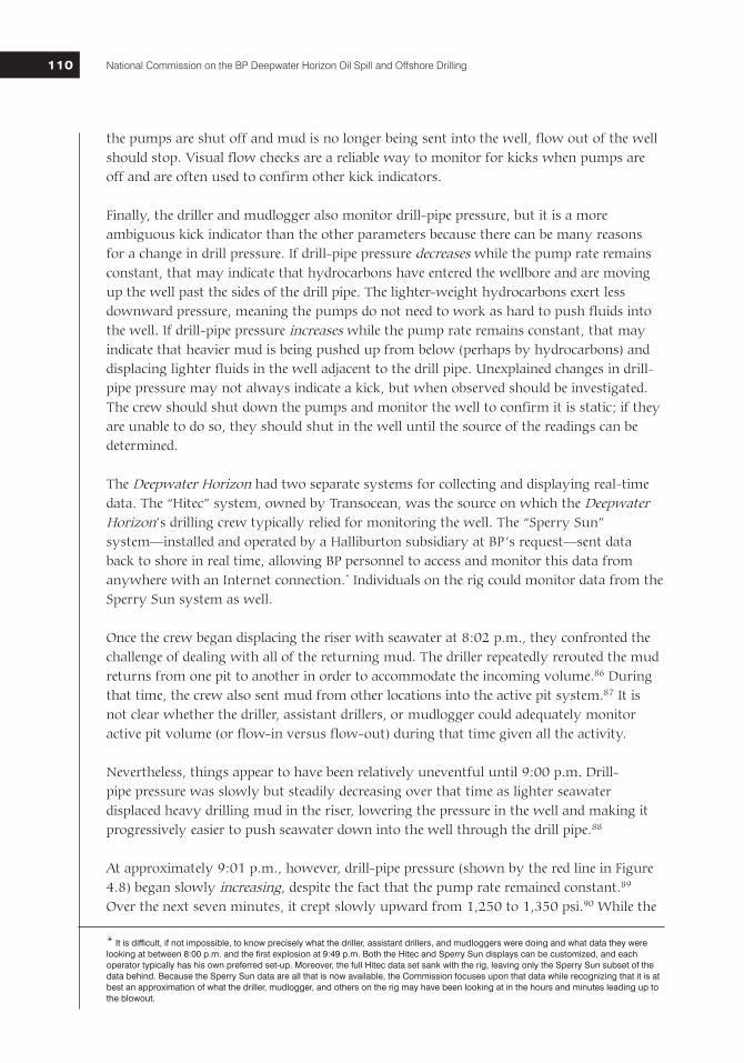
the pumps are shut off and mud is no longer being sent into the well, flow out of the well should stop. Visual flow checks are a reliable way to monitor for kicks when pumps are off and are often used to confirm other kick indicators.
Finally, the driller and mudlogger also monitor drill-pipe pressure, but it is a more ambiguous kick indicator than the other parameters because there can be many reasons for a change in drill pressure. If drill-pipe pressure decreases while the pump rate remains constant, that may indicate that hydrocarbons have entered the wellbore and are moving up the well past the sides of the drill pipe. The lighter-weight hydrocarbons exert less downward pressure, meaning the pumps do not need to work as hard to push fluids into the well. If drill-pipe pressure increases while the pump rate remains constant, that may indicate that heavier mud is being pushed up from below (perhaps by hydrocarbons) and displacing lighter fluids in the well adjacent to the drill pipe. Unexplained changes in drill-pipe pressure may not always indicate a kick, but when observed should be investigated. The crew should shut down the pumps and monitor the well to confirm it is static; if they are unable to do so, they should shut in the well until the source of the readings can be determined.
The Deepwater Horizon had two separate systems for collecting and displaying real-time data. The “Hitec” system, owned by Transocean, was the source on which the Deepwater Horizon’s drilling crew typically relied for monitoring the well. The “Sperry Sun” system—installed and operated by a Halliburton subsidiary at BP’s request—sent data back to shore in real time, allowing BP personnel to access and monitor this data from anywhere with an Internet connection.* Individuals on the rig could monitor data from the Sperry Sun system as well.
Once the crew began displacing the riser with seawater at 8:02 p.m., they confronted the challenge of dealing with all of the returning mud. The driller repeatedly rerouted the mud returns from one pit to another in order to accommodate the incoming volume.86 During that time, the crew also sent mud from other locations into the active pit system.87 It isnot clear whether the driller, assistant drillers, or mudlogger could adequately monitor active pit volume (or flow-in versus flow-out) during that time given all the activity.
Nevertheless, things appear to have been relatively uneventful until 9:00 p.m. Drill-pipe pressure was slowly but steadily decreasing over that time as lighter seawater displaced heavy drilling mud in the riser, lowering the pressure in the well and making it progressively easier to push seawater down into the well through the drill pipe.88
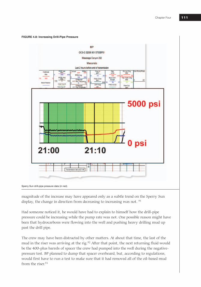
At approximately 9:01 p.m., however, drill-pipe pressure (shown by the red line in Figure 4.8) began slowly increasing, despite the fact that the pump rate remained constant.89 Over the next seven minutes, it crept slowly upward from 1,250 to 1,350 psi.90 While the
* It is difficult, if not impossible, to know precisely what the driller, assistant drillers, and mudloggers were doing and what data they were looking at between 8:00 p.m. and the first explosion at 9:49 p.m. Both the Hitec and Sperry Sun displays can be customized, and each operator typically has his own preferred set-up. Moreover, the full Hitec data set sank with the rig, leaving only the Sperry Sun subset of the data behind. Because the Sperry Sun data are all that is now available, the Commission focuses upon that data while recognizing that it is at best an approximation of what the driller, mudlogger, and others on the rig may have been looking at in the hours and minutes leading up to the blowout.
National Commission on the BP Deepwater Horizon Oil Spill and Offshore Drilling Chapter Four 111111
magnitude of the increase may have appeared only as a subtle trend on the Sperry Sun display, the change in direction from decreasing to increasing was not. 91
Had someone noticed it, he would have had to explain to himself how the drill-pipe pressure could be increasing while the pump rate was not. One possible reason might have been that hydrocarbons were flowing into the well and pushing heavy drilling mud up past the drill pipe.
The crew may have been distracted by other matters. At about that time, the last of the mud in the riser was arriving at the rig.92 After that point, the next returning fluid would be the 400-plus barrels of spacer the crew had pumped into the well during the negative-pressure test. BP planned to dump that spacer overboard, but, according to regulations, would first have to run a test to make sure that it had removed all of the oil-based mud from the riser.93
Sperry Sun drill-pipe pressure data (in red).
FIGURE 4.8: Increasing Drill-Pipe Pressure
National Commission on the BP Deepwater Horizon Oil Spill and Offshore Drilling112
At 9:08 p.m., the crew shut down the pumps to perform this “sheen test.”94 They closed a valve on the flow line that had been carrying fluids from the well to the pit system.95 Mud engineer Greg Meche sampled the fluid and had it tested. Well Site Leader Vidrine waited for confirmation that there was no oily “sheen” on the returning spacer.96 And mudlogger Joseph Keith performed a visual flow check to ensure the well was not flowing while the pumps were off. According to Keith, there was no flow.97
The pumps were shut down for 6 minutes, from 9:08 p.m. to 9:14 p.m. Meche took a sample of the returning fluid from the shaker house* and went to the mud lab to run the test.98 He then returned to the shaker house, weighed the sample, and spoke with another of the mud engineers about the results.99 When Vidrine learned the results, he signed off on the test and the crew turned the pumps back on.100
What nobody appears to have noticed during those six minutes (perhaps as a result of all of the activity) was that drill-pipe pressure was increasing again. With the pumps off, the drill-pipe pressure (red line in yellow box in Figure 4.8) should have stayed constant or gone down. Instead, it went up by approximately 250 psi.101 This increase in pressure was clear in the Sperry Sun data, and likely would have been clearer on the Hitec display. Had someone noticed it, he would have recognized this as a significant anomaly that warranted further investigation before turning the pumps back on. But by 9:14 p.m., the crew turned the pumps back on, obscuring the signal. Drill-pipe pressure increased, but so did the pump rate.102
Four minutes later, a pressure-relief valve on one of the pumps blew.103 Revette organized a group of crewmembers to go to the pump room to fix the valve. The group included derrickhand Wyatt Kemp, floorhands Shane Roshto and Adam Weise, and possibly one of the assistant drillers.104 These men were still attending to the repair at the time of the first explosion.105
At about 9:20 p.m., senior toolpusher Randy Ezell called the rig floor and asked Jason Anderson about the negative-pressure test. Anderson responded that, “It went good.” Ezellthen asked about the displacement. Anderson reassured Ezell, “It’s going fine. . . . I’ve got this.”106
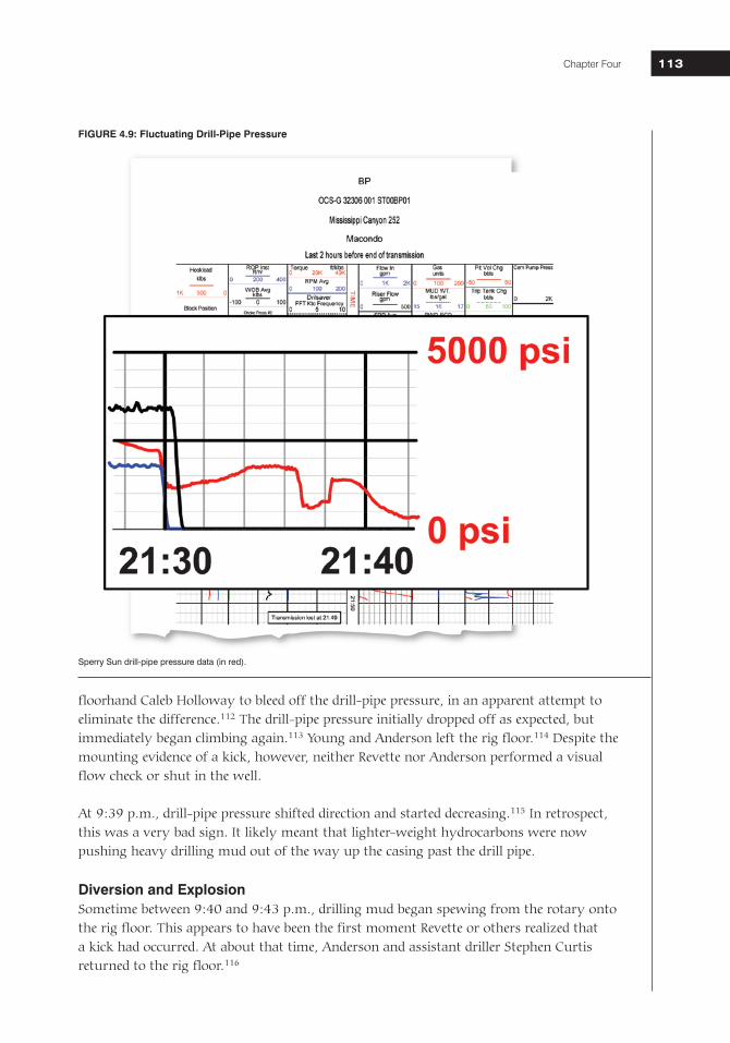
Shortly before 9:30 p.m., Revette noticed an odd and unexpected pressure difference between the drill pipe and the kill line. At roughly 9:30 p.m., the crew shut off the pumps to investigate.107 At about that time, Chief Mate David Young arrived at the rig floor to discuss the upcoming cement plug job with Revette and Anderson.108 Young witnessed Revette and Anderson having a calm discussion about a “differential pressure.”109 Anderson informed Young that the cement plug would be delayed.110 The drill-pipe pressure initially decreased after the pumps were turned off, but then increased by 550 psi over a 5.5 minute period.111 (Figure 4.9) Meanwhile, the pressure on the kill line remained significantly lower. At approximately 9:36 p.m., Revette ordered
* The “shaker house” is a room or small separate structure on the rig for “shale shakers”—sieves and shakers that remove cuttings from the mud as it comes out of the well.
National Commission on the BP Deepwater Horizon Oil Spill and Offshore Drilling Chapter Four 113113
floorhand Caleb Holloway to bleed off the drill-pipe pressure, in an apparent attempt to eliminate the difference.112 The drill-pipe pressure initially dropped off as expected, but immediately began climbing again.113 Young and Anderson left the rig floor.114 Despite the mounting evidence of a kick, however, neither Revette nor Anderson performed a visual flow check or shut in the well.
At 9:39 p.m., drill-pipe pressure shifted direction and started decreasing.115 In retrospect, this was a very bad sign. It likely meant that lighter-weight hydrocarbons were now pushing heavy drilling mud out of the way up the casing past the drill pipe.
Diversion and ExplosionSometime between 9:40 and 9:43 p.m., drilling mud began spewing from the rotary onto the rig floor. This appears to have been the first moment Revette or others realized that a kick had occurred. At about that time, Anderson and assistant driller Stephen Curtis returned to the rig floor.116
Sperry Sun drill-pipe pressure data (in red).
FIGURE 4.9: Fluctuating Drill-Pipe Pressure
National Commission on the BP Deepwater Horizon Oil Spill and Offshore Drilling114
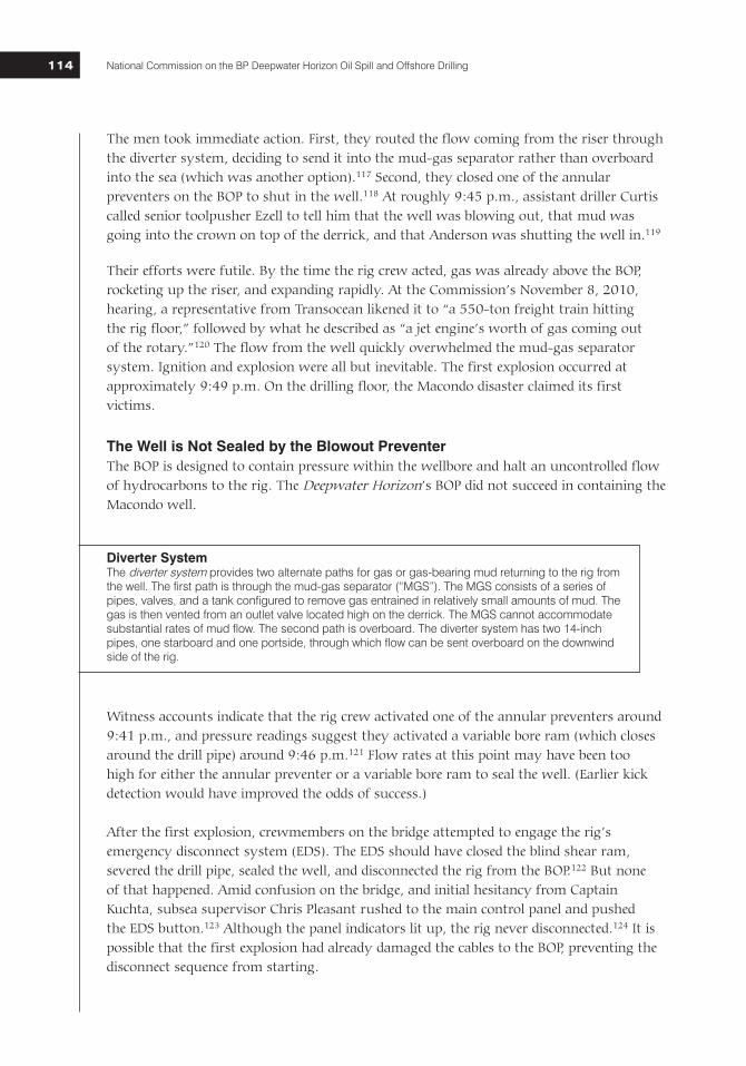
The men took immediate action. First, they routed the flow coming from the riser through the diverter system, deciding to send it into the mud-gas separator rather than overboard into the sea (which was another option).117 Second, they closed one of the annular preventers on the BOP to shut in the well.118 At roughly 9:45 p.m., assistant driller Curtis called senior toolpusher Ezell to tell him that the well was blowing out, that mud was going into the crown on top of the derrick, and that Anderson was shutting the well in.119
Their efforts were futile. By the time the rig crew acted, gas was already above the BOP, rocketing up the riser, and expanding rapidly. At the Commission’s November 8, 2010, hearing, a representative from Transocean likened it to “a 550-ton freight train hitting the rig floor,” followed by what he described as “a jet engine’s worth of gas coming out of the rotary.”120 The flow from the well quickly overwhelmed the mud-gas separator system. Ignition and explosion were all but inevitable. The first explosion occurred at approximately 9:49 p.m. On the drilling floor, the Macondo disaster claimed its first victims.
The Well is Not Sealed by the Blowout PreventerThe BOP is designed to contain pressure within the wellbore and halt an uncontrolled flow of hydrocarbons to the rig. The Deepwater Horizon’s BOP did not succeed in containing the Macondo well.
Witness accounts indicate that the rig crew activated one of the annular preventers around 9:41 p.m., and pressure readings suggest they activated a variable bore ram (which closes around the drill pipe) around 9:46 p.m.121 Flow rates at this point may have been too high for either the annular preventer or a variable bore ram to seal the well. (Earlier kick detection would have improved the odds of success.)
After the first explosion, crewmembers on the bridge attempted to engage the rig’s emergency disconnect system (EDS). The EDS should have closed the blind shear ram, severed the drill pipe, sealed the well, and disconnected the rig from the BOP.122 But none of that happened. Amid confusion on the bridge, and initial hesitancy from Captain Kuchta, subsea supervisor Chris Pleasant rushed to the main control panel and pushed the EDS button.123 Although the panel indicators lit up, the rig never disconnected.124 It is possible that the first explosion had already damaged the cables to the BOP, preventing the disconnect sequence from starting.
Diverter System The diverter system provides two alternate paths for gas or gas-bearing mud returning to the rig from the well. The first path is through the mud-gas separator (“MGS”). The MGS consists of a series of pipes, valves, and a tank configured to remove gas entrained in relatively small amounts of mud. The gas is then vented from an outlet valve located high on the derrick. The MGS cannot accommodate substantial rates of mud flow. The second path is overboard. The diverter system has two 14-inch pipes, one starboard and one portside, through which flow can be sent overboard on the downwind side of the rig.
National Commission on the BP Deepwater Horizon Oil Spill and Offshore Drilling Chapter Four 115115
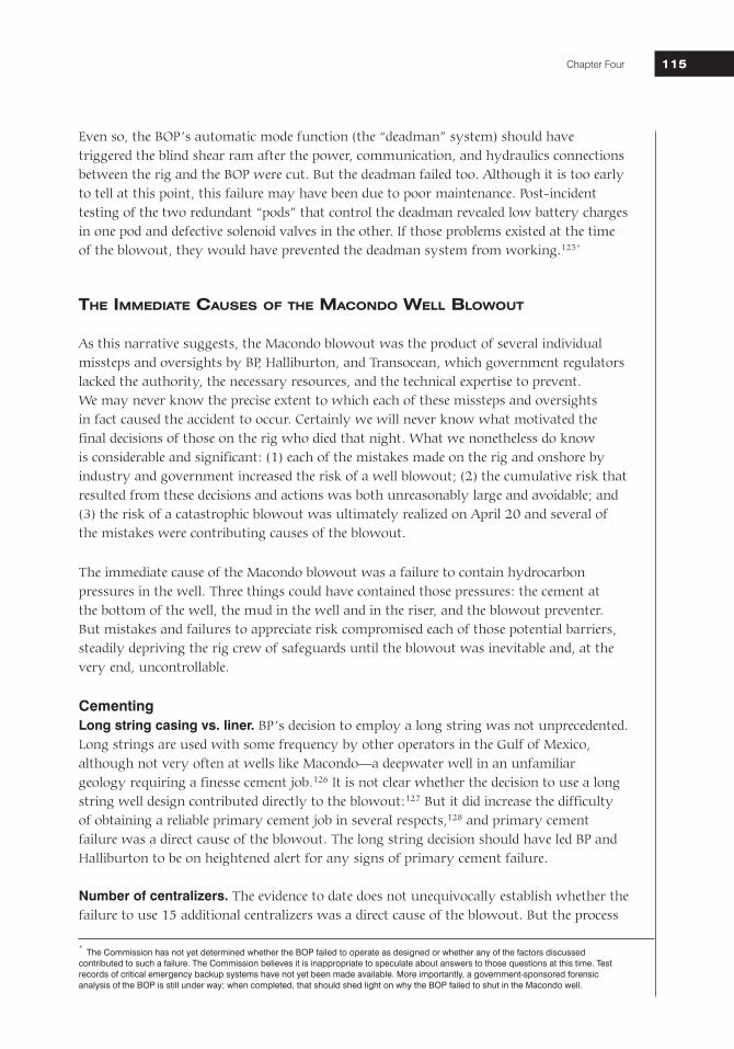
Even so, the BOP’s automatic mode function (the “deadman” system) should have triggered the blind shear ram after the power, communication, and hydraulics connections between the rig and the BOP were cut. But the deadman failed too. Although it is too early to tell at this point, this failure may have been due to poor maintenance. Post-incident testing of the two redundant “pods” that control the deadman revealed low battery charges in one pod and defective solenoid valves in the other. If those problems existed at the time of the blowout, they would have prevented the deadman system from working.125*
The ImmedIaTe Causes of The maCondo Well BloWouT
As this narrative suggests, the Macondo blowout was the product of several individual missteps and oversights by BP, Halliburton, and Transocean, which government regulators lacked the authority, the necessary resources, and the technical expertise to prevent. We may never know the precise extent to which each of these missteps and oversights in fact caused the accident to occur. Certainly we will never know what motivated the final decisions of those on the rig who died that night. What we nonetheless do know is considerable and significant: (1) each of the mistakes made on the rig and onshore by industry and government increased the risk of a well blowout; (2) the cumulative risk that resulted from these decisions and actions was both unreasonably large and avoidable; and (3) the risk of a catastrophic blowout was ultimately realized on April 20 and several of the mistakes were contributing causes of the blowout.
The immediate cause of the Macondo blowout was a failure to contain hydrocarbon pressures in the well. Three things could have contained those pressures: the cement at the bottom of the well, the mud in the well and in the riser, and the blowout preventer. But mistakes and failures to appreciate risk compromised each of those potential barriers, steadily depriving the rig crew of safeguards until the blowout was inevitable and, at the very end, uncontrollable.
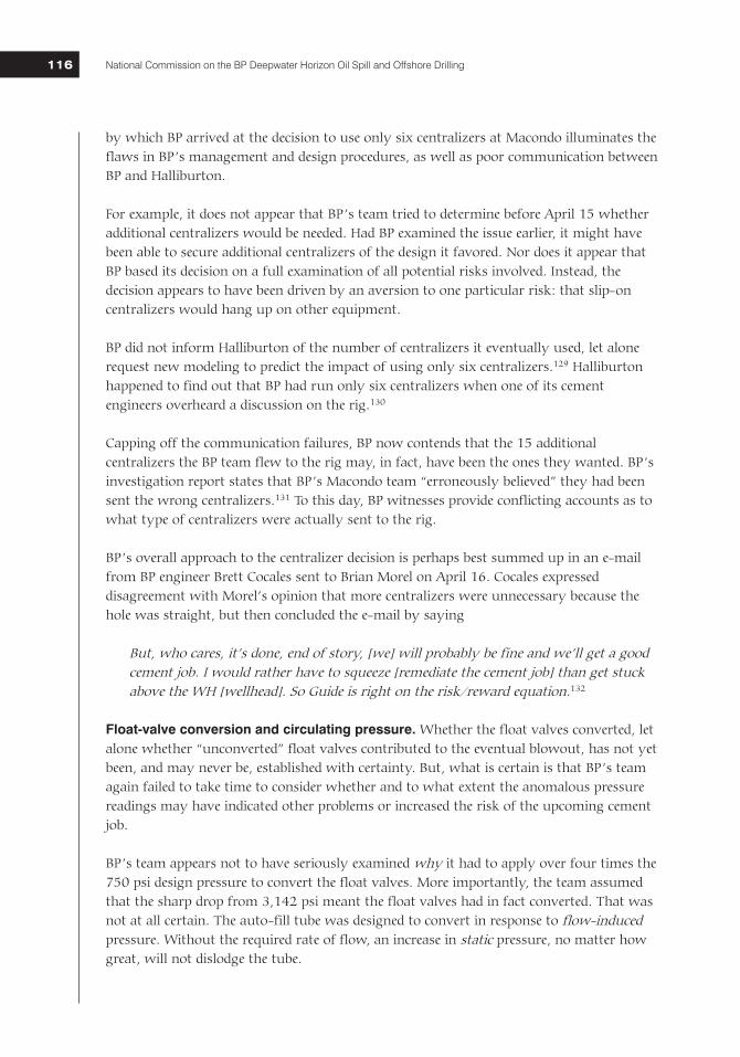
CementingLong string casing vs. liner. BP’s decision to employ a long string was not unprecedented. Long strings are used with some frequency by other operators in the Gulf of Mexico, although not very often at wells like Macondo—a deepwater well in an unfamiliar geology requiring a finesse cement job.126 It is not clear whether the decision to use a long string well design contributed directly to the blowout:127 But it did increase the difficulty of obtaining a reliable primary cement job in several respects,128 and primary cement failure was a direct cause of the blowout. The long string decision should have led BP and Halliburton to be on heightened alert for any signs of primary cement failure. Number of centralizers. The evidence to date does not unequivocally establish whether the failure to use 15 additional centralizers was a direct cause of the blowout. But the process
* The Commission has not yet determined whether the BOP failed to operate as designed or whether any of the factors discussed contributed to such a failure. The Commission believes it is inappropriate to speculate about answers to those questions at this time. Test records of critical emergency backup systems have not yet been made available. More importantly, a government-sponsored forensic analysis of the BOP is still under way; when completed, that should shed light on why the BOP failed to shut in the Macondo well.
National Commission on the BP Deepwater Horizon Oil Spill and Offshore Drilling116
by which BP arrived at the decision to use only six centralizers at Macondo illuminates the flaws in BP’s management and design procedures, as well as poor communication between BP and Halliburton.
For example, it does not appear that BP’s team tried to determine before April 15 whether additional centralizers would be needed. Had BP examined the issue earlier, it might have been able to secure additional centralizers of the design it favored. Nor does it appear that BP based its decision on a full examination of all potential risks involved. Instead, the decision appears to have been driven by an aversion to one particular risk: that slip-on centralizers would hang up on other equipment.
BP did not inform Halliburton of the number of centralizers it eventually used, let alone request new modeling to predict the impact of using only six centralizers.129 Halliburton happened to find out that BP had run only six centralizers when one of its cement engineers overheard a discussion on the rig.130
Capping off the communication failures, BP now contends that the 15 additional centralizers the BP team flew to the rig may, in fact, have been the ones they wanted. BP’s investigation report states that BP’s Macondo team “erroneously believed” they had been sent the wrong centralizers.131 To this day, BP witnesses provide conflicting accounts as to what type of centralizers were actually sent to the rig.
BP’s overall approach to the centralizer decision is perhaps best summed up in an e-mail from BP engineer Brett Cocales sent to Brian Morel on April 16. Cocales expressed disagreement with Morel’s opinion that more centralizers were unnecessary because the hole was straight, but then concluded the e-mail by saying
But, who cares, it’s done, end of story, [we] will probably be fine and we’ll get a good cement job. I would rather have to squeeze [remediate the cement job] than get stuck above the WH [wellhead]. So Guide is right on the risk/reward equation.132
Float-valve conversion and circulating pressure. Whether the float valves converted, let alone whether “unconverted” float valves contributed to the eventual blowout, has not yet been, and may never be, established with certainty. But, what is certain is that BP’s team again failed to take time to consider whether and to what extent the anomalous pressure readings may have indicated other problems or increased the risk of the upcoming cement job.
BP’s team appears not to have seriously examined why it had to apply over four times the 750 psi design pressure to convert the float valves. More importantly, the team assumed that the sharp drop from 3,142 psi meant the float valves had in fact converted. That was not at all certain. The auto-fill tube was designed to convert in response to flow-induced pressure. Without the required rate of flow, an increase in static pressure, no matter how great, will not dislodge the tube.
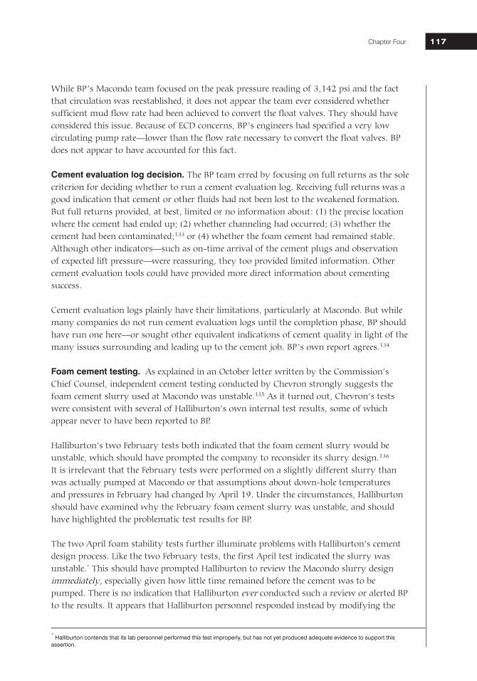
National Commission on the BP Deepwater Horizon Oil Spill and Offshore Drilling Chapter Four 117117
While BP’s Macondo team focused on the peak pressure reading of 3,142 psi and the fact that circulation was reestablished, it does not appear the team ever considered whether sufficient mud flow rate had been achieved to convert the float valves. They should have considered this issue. Because of ECD concerns, BP’s engineers had specified a very low circulating pump rate—lower than the flow rate necessary to convert the float valves. BP does not appear to have accounted for this fact. Cement evaluation log decision. The BP team erred by focusing on full returns as the sole criterion for deciding whether to run a cement evaluation log. Receiving full returns was a good indication that cement or other fluids had not been lost to the weakened formation. But full returns provided, at best, limited or no information about: (1) the precise location where the cement had ended up; (2) whether channeling had occurred; (3) whether the cement had been contaminated;133 or (4) whether the foam cement had remained stable. Although other indicators—such as on-time arrival of the cement plugs and observation of expected lift pressure—were reassuring, they too provided limited information. Other cement evaluation tools could have provided more direct information about cementing success.
Cement evaluation logs plainly have their limitations, particularly at Macondo. But while many companies do not run cement evaluation logs until the completion phase, BP should have run one here—or sought other equivalent indications of cement quality in light of the many issues surrounding and leading up to the cement job. BP’s own report agrees.134
Foam cement testing. As explained in an October letter written by the Commission’s Chief Counsel, independent cement testing conducted by Chevron strongly suggests the foam cement slurry used at Macondo was unstable.135 As it turned out, Chevron’s tests were consistent with several of Halliburton’s own internal test results, some of which appear never to have been reported to BP.
Halliburton’s two February tests both indicated that the foam cement slurry would be unstable, which should have prompted the company to reconsider its slurry design.136 It is irrelevant that the February tests were performed on a slightly different slurry than was actually pumped at Macondo or that assumptions about down-hole temperatures and pressures in February had changed by April 19. Under the circumstances, Halliburton should have examined why the February foam cement slurry was unstable, and should have highlighted the problematic test results for BP.
The two April foam stability tests further illuminate problems with Halliburton’s cement design process. Like the two February tests, the first April test indicated the slurry was unstable.* This should have prompted Halliburton to review the Macondo slurry design immediately, especially given how little time remained before the cement was to be pumped. There is no indication that Halliburton ever conducted such a review or alerted BP to the results. It appears that Halliburton personnel responded instead by modifying the
* Halliburton contends that its lab personnel performed this test improperly, but has not yet produced adequate evidence to support this assertion.
National Commission on the BP Deepwater Horizon Oil Spill and Offshore Drilling118
test conditions—specifically, the pre-testing conditioning time—and thereby achieving an arguably successful test result.
Halliburton has to date provided nothing to suggest that its personnel selected the final conditioning time based on any sort of disciplined technical analysis of the Macondo well conditions.137 Moreover, Halliburton has not yet provided the Commission with evidence to support its view that cement should be “conditioned” for an extended time before stability testing. Given the apparent importance of this view, it should have been supported by careful pre-incident technical analysis and actual physical testing. At present, it appears only to be an unconfirmed hypothesis.
Even more serious, Halliburton documents strongly suggest that the final foam stability test results indicating a stable slurry may not even have been available before Halliburton pumped the primary cement job at Macondo.138 If true, Halliburton pumped foam cement into the well at Macondo at a time when all available test data showed the cement would be, in fact, unstable.
Risk evaluation of Macondo cementing decisions and procedures. BP’s fundamental mistake was its failure—notwithstanding the inherent uncertainty of cementing and the many specific risk factors surrounding the cement job at Macondo—to exercise special caution (and, accordingly, to direct its contractors to be especially vigilant) before relying on the primary cement as a barrier to hydrocarbon flow.
Those decisions and risk factors included, among other things: • Difficult drilling conditions, including serious lost returns in the cementing zone;• Difficulty converting float equipment and low circulating pressure after purported
conversion;• No bottoms up circulation;• Less than recommended number of centralizers;• Low rate of cement flow; and• Low cement volume.
Based on evidence currently available, there is nothing to suggest that BP’s engineering team conducted a formal, disciplined analysis of the combined impact of these risk factors on the prospects for a successful cement job. There is nothing to suggest that BP communicated a need for elevated vigilance after the job. And there is nothing to indicate that Halliburton highlighted to BP or others the relative difficulty of BP’s cementing plan before, during, or after the job, or that it recommended any post-cementing measures to confirm that the primary cement had in fact isolated the high-pressure hydrocarbons in the pay zone.
Negative-Pressure Test Even when there is no reason for concern about a cement job, a negative-pressure test is “very important.”139 By sending Schlumberger’s cement evaluation team back to shore, BP chose to rely entirely on the negative-pressure test to directly evaluate the integrity of the primary cement at Macondo.
National Commission on the BP Deepwater Horizon Oil Spill and Offshore Drilling Chapter Four 119119
It is now undisputed that the negative-pressure test at Macondo was conducted and interpreted improperly. For instance, BP used a spacer that had not been used by anyone at BP or on the rig before, that was not fully tested, and that may have clogged the kill line.140 The pressure data were not ambiguous. Rather, they showed repeatedly that formation fluids, in this case hydrocarbons, were flowing into the well. The failure to properly conduct and interpret the negative-pressure test was a major contributing factor to the blowout.
Given the risk factors surrounding the primary cement job and other prior unusual events (such as difficulty converting the float valves), the BP Well Site Leaders and, to the extent they were aware of the issues, the Transocean crew should have been particularly sensitive to anomalous pressure readings and ready to accept that the primary cement job could have failed.141 It appears instead they started from the assumption that the well could not be flowing, and kept running tests and coming up with various explanations until they had convinced themselves their assumption was correct.142
The Commission has identified a number of potential factors that may have contributed to the failure to properly conduct and interpret the negative pressure test that night:
• First, there was no standard procedure for running or interpreting the test in either MMS regulations or written industry protocols. Indeed, the regulations and standards did not require BP to run a negative-pressure test at all.
• Second, BP and Transocean had no internal procedures for running or interpreting negative-pressure tests, and had not formally trained their personnel in how to do so.
• Third, the BP Macondo team did not provide the Well Site Leaders or rig crew with specific procedures for performing the negative-pressure test at Macondo.
• Fourth, BP did not have in place (or did not enforce) any policy that would have required personnel to call back to shore for a second opinion about confusing data.
• Finally, due to poor communication, it does not appear that the men performing and interpreting the test had a full appreciation of the context in which they were performing it. Such an appreciation might have increased their willingness to believe the well was flowing. Context aside, however, individuals conducting and interpreting the negative-pressure test should always do so with an expectation that the well might lack integrity.
Temporary Abandonment Procedures Another factor that may have contributed to the blowout was BP’s temporary abandonment procedure.
First, it was not necessary or advisable for BP to replace 3,300 feet of mud below the mud line with seawater. By replacing that much heavy drilling mud with much lighter
National Commission on the BP Deepwater Horizon Oil Spill and Offshore Drilling120
seawater, BP placed more stress on the cement job at the bottom of the well than necessary. BP’s stated reason for doing so was its preference for setting cement plugs in seawater rather than mud.143 While industry experts have acknowledged that setting cement plugs in seawater can avoid mud contamination and that it is not unusual for operators to set cement plugs in seawater,144 BP has provided no evidence that it or another operator has ever set a surface cement plug so deep in seawater (particularly without additional barriers). The risks BP created by its decision to displace 3,300 feet of mud with seawater outweighed its concerns about cement setting better in seawater than in mud. As BP has admitted, cement plugs can be set in mud.145 BP also could have set one or more non-cement bridge plugs (which work equally well in mud or seawater).146 No evidence has yet been produced that the BP team ever formally evaluated these options or the relative risks created by removing 3,300 feet of mud.
It was not necessary to set the cement plug 3,300 feet below the mudline. The BP Macondo team chose to do so in order to set the lockdown sleeve last in the temporary abandonment sequence to minimize the chances of damage to the sleeve. Setting the lockdown sleeve would require 100,000 pounds of force. The BP Macondo team sought to generate that force by hanging 3,000 feet of drill pipe below the sleeve—hence the desire to set the cement plug 3,000 feet below the mud line. BP’s desire to set the lockdown sleeve last did not justify the risks its decision created. BP could have used other proven means to protect the lockdown sleeve if set earlier in the process. It also did not need 3,000 feet of space to generate 100,000 pounds of force.147 Merrick Kelley, the individual at BP in charge of lockdown sleeves in the Gulf of Mexico, told Commission staff that he had recommended setting the plug roughly 1,300 feet below the mud line (using heavier drill pipe), rather than 3,300 feet down. That would have significantly increased the margin of safety for the well.148
The most troubling aspect of BP’s temporary abandonment procedure was BP’s decision to displace mud from the riser before setting the surface cement plug or other barrier in the production casing.149 During displacement of the riser, the BOP would be open, leaving the cement at the bottom of the well (in the annulus and shoe track) as the only physical barrier to flow up the production casing between the pay zone and the rig.150 Relying so heavily on primary cement integrity put a significant premium on the negative-pressure test and well monitoring during displacement, both of which are subject to human error. BP’s decision under these circumstances to displace mud from the riser before setting another barrier unnecessarily and substantially increased the risk of a blowout. BP could have set the surface cement plug, or a mechanical plug, before displacing the riser.151 BP could have replaced the mud in the wellbore with heavier mud sufficient to overbalance the well.152 It is not apparent why BP chose not to do any of these things.
Kick Detection The drilling crew and other individuals on the rig also missed critical signs that a kick was occurring. The crew could have prevented the blowout—or at least significantly reduced its impact—if they had reacted in a timely and appropriate manner. What is not now clear is precisely why the crew missed these signals.
National Commission on the BP Deepwater Horizon Oil Spill and Offshore Drilling Chapter Four 121121
The Sperry Sun data available to the crew from between 8:00 p.m. and 9:49 p.m. reveal a number of different signals that if observed, should at least have prompted the driller to investigate further, for instance, by conducting a visual flow check, and then shutting in the well if there were indications of flow. For instance, the increasing drill-pipe pressure after the pumps were shut down for the sheen test at 9:08 p.m. was a clear signal that something was happening in the well. Similarly, at roughly 9:30 p.m., the driller and toolpusher recognized an anomalous pressure difference between the drill pipe and kill line.153 Both of these signals should have prompted action—especially the latter: it was clearly recognized by the crew and echoed the odd pressure readings observed during the negative-pressure test. The crew should have done a flow check and shut in the well immediately upon confirmation of flow.
Why did the crew miss or misinterpret these signals? One possible reason is that they had done a number of things that confounded their ability to interpret signals from the well. For instance, after 9:08 p.m., the crew began sending fluids returning from the well overboard, bypassing the active pit system and the flow-out meter (at least the Sperry Sun flow-out meter). Only the mudlogger performed a visual flow check.154
It was neither necessary nor advisable—particularly where the cement at the bottom (in the annulus and shoe track) was the only barrier between the rig and pay zone—to bypass the active system and flow-out meter or to perform potentially confounding simultaneous operations during displacement of the riser. For instance, the crew could have routed the seawater through the active pit system before sending it into the well.
In the future, the instrumentation and displays used for well monitoring must be improved. There is no apparent reason why more sophisticated, automated alarms and algorithms cannot be built into the display system to alert the driller and mudlogger when anomalies arise. These individuals sit for 12 hours at a time in front of these displays. In light of the potential consequences, it is no longer acceptable to rely on a system that requires the right person to be looking at the right data at the right time, and then to understand its significance in spite of simultaneous activities and other monitoring responsibilities.
Diversion and Blowout Preventer Activation The crew should have diverted the flow overboard when mud started spewing from the rig floor. While that ultimately may not have prevented an explosion, diverting overboard would have reduced the risk of ignition of the rising gas. Considering the circumstances, the crew also should have activated the blind shear ram to close in the well. Diverting the flow overboard and/or activating the blind shear ram may not have prevented the explosion, but likely could have given the crew more time and perhaps limited the impact of the explosion.

National Commission on the BP Deepwater Horizon Oil Spill and Offshore Drilling122
There are a few possible explanations for why the crew did neither:
• First, they may not have recognized the severity of the situation, though that seems unlikely given the amount of mud that spewed from the rig floor.
• Second, they did not have much time to act. The explosion occurred roughly six to eight minutes after mud first emerged onto the rig floor.
• Finally, and perhaps most significantly, the rig crew had not been trained adequately how to respond to such an emergency situation. In the future, well-control training should include simulations and drills for such emergencies—including the momentous decision to engage the blind shear rams or trigger the EDS.
The Root Causes: Failures in Industry and Government
Overarching Management Failures by IndustryWhatever irreducible uncertainty may persist regarding the precise contribution to the blowout of each of several potentially immediate causes, no such uncertainty exists about the blowout’s root causes. The blowout was not the product of a series of aberrational decisions made by rogue industry or government officials that could not have been anticipated or expected to occur again. Rather, the root causes are systemic and, absent significant reform in both industry practices and government policies, might well recur. The missteps were rooted in systemic failures by industry management (extending beyond BP to contractors that serve many in the industry), and also by failures of government to provide effective regulatory oversight of offshore drilling.
The most significant failure at Macondo—and the clear root cause of the blowout—was a failure of industry management. Most, if not all, of the failures at Macondo can be traced back to underlying failures of management and communication. Better management of decisionmaking processes within BP and other companies, better communication within and between BP and its contractors, and effective training of key engineering and rig personnel would have prevented the Macondo incident. BP and other operators must have effective systems in place for integrating the various corporate cultures, internal procedures, and decisionmaking protocols of the many different contractors involved in drilling a deepwater well.
BP’s management process did not adequately identify or address risks created by late changes to well design and procedures. BP did not have adequate controls in place to ensure that key decisions in the months leading up to the blowout were safe or sound from an engineering perspective. While initial well design decisions undergo a serious peer-review process155 and changes to well design are subsequently subject to a management of change (MOC) process,156 changes to drilling procedures in the weeks and days before implementation are typically not subject to any such peer-review or MOC process. At Macondo, such decisions appear to have been made by the BP Macondo team in ad hoc
National Commission on the BP Deepwater Horizon Oil Spill and Offshore Drilling Chapter Four 123123
fashion without any formal risk analysis or internal expert review.157 This appears to have been a key causal factor of the blowout.
A few obvious examples, such as the last-minute confusion regarding whether to run six or 21 centralizers, have already been highlighted. Another clear example is provided by the temporary abandonment procedure used at Macondo. As discussed earlier, that procedure changed dramatically and repeatedly during the week leading up to the blowout. As of April 12, the plan was to set the cement plug in seawater less than 1,000 feet below the mud line after setting the lockdown sleeve. Two days later, Morel sent an e-mail in which the procedure was to set the cement plug in mud before displacing the riser with seawater. By April 20, the plan had morphed into the one set forth in the “Ops Note”: the crew would remove 3,300 feet of mud from below the mud line and set the cement plug after the riser had been displaced.
There is no readily discernible reason why these temporary abandonment procedures could not have been more thoroughly and rigorously vetted earlier in the design process.158 It does not appear that the changes to the temporary abandonment procedures went through any sort of formal review at all.
Halliburton and BP’s management processes did not ensure that cement was adequately tested. Halliburton had insufficient controls in place to ensure that laboratory testing was performed in a timely fashion or that test results were vetted rigorously in-house or with the client. In fact, it appears that Halliburton did not even have testing results in its possession showing the Macondo slurry was stable until after the job had been pumped. It is difficult to imagine a clearer failure of management or communication.
The story of the foam stability tests may illuminate management problems within BP as well. By early April, BP team members had recognized the importance of timely cement testing.159 And by mid-April, BP’s team had identified concerns regarding the timeliness of Halliburton’s testing process.160 But despite their recognition that final changes to the cement design (made to accommodate their concerns about lost returns) might increase the risks of foam instability,161 BP personnel do not appear to have insisted that Halliburton complete its foam stability tests—let alone report the results to BP for review—before ordering primary cementing to begin.
BP, Transocean, and Halliburton failed to communicate adequately. Information appears to have been excessively compartmentalized at Macondo as a result of poor communication. BP did not share important information with its contractors, or sometimes internally even with members of its own team. Contractors did not share important information with BP or each other. As a result, individuals often found themselves making critical decisions without a full appreciation for the context in which they were being made (or even without recognition that the decisions were critical).
For example, many BP and Halliburton employees were aware of the difficulty of the primary cement job. But those issues were for the most part not communicated to the rig crew that conducted the negative-pressure test and monitored the well. It appears that
National Commission on the BP Deepwater Horizon Oil Spill and Offshore Drilling124
BP did not even communicate many of those issues to its own personnel on the rig—in particular to Bob Kaluza, who was on his first hitch as a Well Site Leader on the Deepwater Horizon. Similarly, it appears at this time that the BP Well Site Leaders did not consult anyone on shore about the anomalous data observed during the negative-pressure test.162 Had they done so, the Macondo blowout may not have happened.
Transocean failed to adequately communicate lessons from an earlier near-miss to its crew. Transocean failed to adequately communicate to its crew lessons learned from an eerily similar near-miss on one of its rigs in the North Sea four months prior to the Macondo blowout. On December 23, 2009, gas entered the riser on that rig while the crew was displacing a well with seawater during a completion operation. As at Macondo, the rig’s crew had already run a negative-pressure test on the lone physical barrier between the pay zone and the rig, and had declared the test a success.163 The tested barrier nevertheless failed during displacement, resulting in an influx of hydrocarbons. Mud spewed onto the rig floor—but fortunately the crew was able to shut in the well before a blowout occurred.164 Nearly one metric ton of oil-based mud ended up in the ocean. The incident cost Transocean 11.2 days of additional work and more than 5 million British pounds in expenses.165
Transocean subsequently created an internal PowerPoint presentation warning that “[t]ested barriers can fail” and that “risk perception of barrier failure was blinkered by the positive inflow test [negative test].”166 The presentation noted that “[f]luid displacements for inflow test [negative test] and well clean up operations are not adequately covered in our well control manual or adequately cover displacements in under balanced operations.”167 It concluded with a slide titled “Are we ready?” and “WHAT IF?” containing the bullet points: “[h]igh vigilance when reduced to one barrier underbalanced,” “[r]ecognise when going underbalanced—heightened vigilance,” and “[h]ighlight what the kick indicators are when not drilling.”168
Transocean eventually sent out an “operations advisory” to some of its fleet (in the North Sea) on April 14, 2010, reiterating many of the lessons learned and warnings from the presentation. It set out “mandatory” actions to take, acknowledging a “Lack of Well Control preparedness during completion phase,” requiring that “[s]tandard well control practices must be maintained through the life span of the well” and stating that “[w]ell programs must specify operations where a single mechanical barrier . . . is in effect and a warning must be included to raise awareness. . . .”169
The language in this “advisory” is less pointed and vivid than the language in the earlier PowerPoint. Moreover, according to Transocean, neither the PowerPoint nor this advisory ever made it to the Deepwater Horizon crew.170
Transocean has suggested that the North Sea incident and advisory were irrelevant to what happened in the Gulf of Mexico. The December incident in the North Sea occurred during the completion phase and involved failure of a different tested barrier. Those are largely
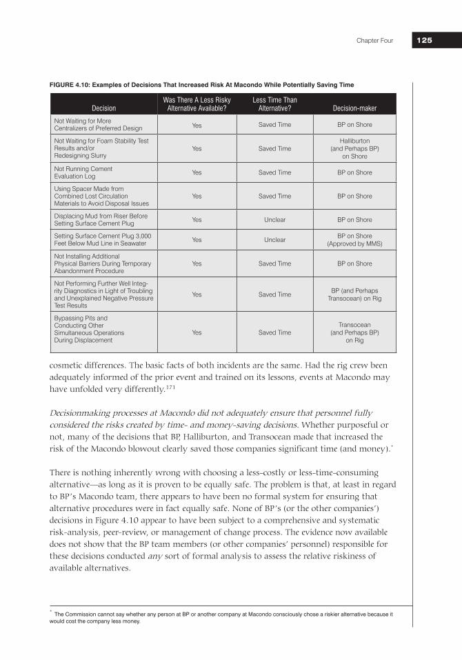
National Commission on the BP Deepwater Horizon Oil Spill and Offshore Drilling Chapter Four 125125
cosmetic differences. The basic facts of both incidents are the same. Had the rig crew been adequately informed of the prior event and trained on its lessons, events at Macondo may have unfolded very differently.171
Decisionmaking processes at Macondo did not adequately ensure that personnel fully considered the risks created by time- and money-saving decisions. Whether purposeful or not, many of the decisions that BP, Halliburton, and Transocean made that increased the risk of the Macondo blowout clearly saved those companies significant time (and money).*
There is nothing inherently wrong with choosing a less-costly or less-time-consuming alternative—as long as it is proven to be equally safe. The problem is that, at least in regard to BP’s Macondo team, there appears to have been no formal system for ensuring that alternative procedures were in fact equally safe. None of BP’s (or the other companies’) decisions in Figure 4.10 appear to have been subject to a comprehensive and systematic risk-analysis, peer-review, or management of change process. The evidence now available does not show that the BP team members (or other companies’ personnel) responsible for these decisions conducted any sort of formal analysis to assess the relative riskiness of available alternatives.
* The Commission cannot say whether any person at BP or another company at Macondo consciously chose a riskier alternative because it would cost the company less money.
FIGURE 4.10: Examples of Decisions That Increased Risk At Macondo While Potentially Saving Time
DecisionWas There A Less Risky
Alternative Available?Less Time Than
Alternative? Decision-maker
Not Waiting for More Centralizers of Preferred Design Yes Saved Time BP on Shore
Not Waiting for Foam Stability Test Results and/or Redesigning Slurry
Yes Saved TimeHalliburton
(and Perhaps BP)on Shore
Not Running Cement Evaluation Log Yes Saved Time BP on Shore
Using Spacer Made from Combined Lost Circulation Materials to Avoid Disposal Issues
Yes Saved Time BP on Shore
Displacing Mud from Riser Before Setting Surface Cement Plug Yes Unclear BP on Shore
Setting Surface Cement Plug 3,000 Feet Below Mud Line in Seawater Yes Unclear
BP on Shore(Approved by MMS)
Not Installing Additional Physical Barriers During Temporary Abandonment Procedure
Yes Saved Time BP on Shore
Not Performing Further Well Integ-rity Diagnostics in Light of Troubling and Unexplained Negative Pressure Test Results
Yes Saved TimeBP (and Perhaps
Transocean) on Rig
Bypassing Pits and Conducting Other Simultaneous Operations During Displacement
Yes Saved TimeTransocean
(and Perhaps BP) on Rig
National Commission on the BP Deepwater Horizon Oil Spill and Offshore Drilling126
Corporations understandably encourage cost-saving and efficiency. But given the dangers of deepwater drilling, companies involved must have in place strict policies requiring rigorous analysis and proof that less-costly alternatives are in fact equally safe. If BP had any such policies in place, it does not appear that its Macondo team adhered to them. Unless companies create and enforce such policies, there is simply too great a risk that financial pressures will systematically bias decisionmaking in favor of time- and cost-savings. It is also critical (as described in greater length in Chapter 8) that companies implement and maintain a pervasive top-down safety culture (such as the ones described by the ExxonMobil and Shell CEOs at the Commission’s hearing on November 9, 2010) that reward employees and contractors who take action when there is a safety concern even though such action costs the company time and money.172
Of course, some decisions will have shorter timelines than others, and a full-blown peer-reviewed risk analysis is not always practicable. But even where decisions need to be made in relatively short order, there must be systems in place to ensure that some sort of formal risk analysis takes place when procedures are changed, and that the analysis considers the impact of the decision in the context of all system risks. If it turns out there is insufficient time to perform such an analysis, only proven alternatives should be considered.
Regulatory Failures Government also failed to provide the oversight necessary to prevent these lapses in judgment and management by private industry. As discussed in Chapter 3, MMS regulations were inadequate to address the risks of deepwater drilling. Many critical aspects of drilling operations were left to industry to decide without agency review. For instance, there was no requirement, let alone protocol, for a negative-pressure test, the misreading of which was a major contributor to the Macondo blowout. Nor were there detailed requirements related to the testing of the cement essential for well stability.
Responsibilities for these shortfalls are best not assigned to MMS alone. The root cause can be better found by considering how, as described in Chapter 3, efforts to expand regulatory oversight, tighten safety requirements, and provide funding to equip regulators with the resources, personnel, and training needed to be effective were either overtly resisted or not supported by industry, members of Congress, and several administrations. As a result, neither the regulations nor the regulators were asking the tough questions or requiring the demonstration of preparedness that could have avoided the Macondo disaster.
But even if MMS had the resources and political support needed to promulgate the kinds of regulations necessary to reduce risk, it would still have lacked personnel with the kinds of expertise and training needed to enforce those regulations effectively. The significance of inadequate training is underscored by MMS’s approval of BP’s request to set its temporary abandonment plug 3,300 feet below the mud line. At least in this instance, there was a MMS regulation that potentially applied. MMS regulations state that cement plugs for temporary abandonment should normally be installed “no more than 1,000 feet below the mud line,” but also allow the agency to approve “alternate requirements for subsea wells case-by-case.”173 Crucially, alternate procedures “must provide a level of safety and environmental protection that equals or surpasses current MMS requirements.”174
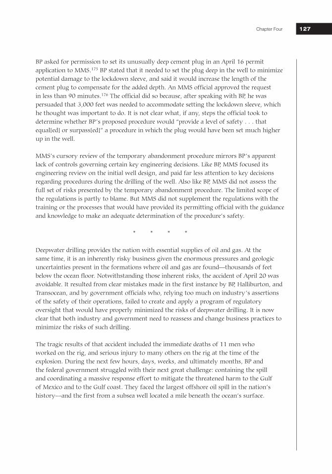
National Commission on the BP Deepwater Horizon Oil Spill and Offshore Drilling Chapter Four 127127
BP asked for permission to set its unusually deep cement plug in an April 16 permit application to MMS.175 BP stated that it needed to set the plug deep in the well to minimize potential damage to the lockdown sleeve, and said it would increase the length of the cement plug to compensate for the added depth. An MMS official approved the request in less than 90 minutes.176 The official did so because, after speaking with BP, he was persuaded that 3,000 feet was needed to accommodate setting the lockdown sleeve, which he thought was important to do. It is not clear what, if any, steps the official took to determine whether BP’s proposed procedure would “provide a level of safety . . . that equal[ed] or surpass[ed]” a procedure in which the plug would have been set much higher up in the well.
MMS’s cursory review of the temporary abandonment procedure mirrors BP’s apparent lack of controls governing certain key engineering decisions. Like BP, MMS focused its engineering review on the initial well design, and paid far less attention to key decisions regarding procedures during the drilling of the well. Also like BP, MMS did not assess the full set of risks presented by the temporary abandonment procedure. The limited scope of the regulations is partly to blame. But MMS did not supplement the regulations with the training or the processes that would have provided its permitting official with the guidance and knowledge to make an adequate determination of the procedure’s safety.
* * * *
Deepwater drilling provides the nation with essential supplies of oil and gas. At the same time, it is an inherently risky business given the enormous pressures and geologic uncertainties present in the formations where oil and gas are found—thousands of feet below the ocean floor. Notwithstanding those inherent risks, the accident of April 20 was avoidable. It resulted from clear mistakes made in the first instance by BP, Halliburton, and Transocean, and by government officials who, relying too much on industry’s assertions of the safety of their operations, failed to create and apply a program of regulatory oversight that would have properly minimized the risks of deepwater drilling. It is now clear that both industry and government need to reassess and change business practices to minimize the risks of such drilling.
The tragic results of that accident included the immediate deaths of 11 men who worked on the rig, and serious injury to many others on the rig at the time of the explosion. During the next few hours, days, weeks, and ultimately months, BP and the federal government struggled with their next great challenge: containing the spill and coordinating a massive response effort to mitigate the threatened harm to the Gulf of Mexico and to the Gulf coast. They faced the largest offshore oil spill in the nation’s history—and the first from a subsea well located a mile beneath the ocean’s surface.
National Commission on the BP Deepwater Horizon Oil Spill and Offshore Drilling128
ENDNOTESThe Commission has reviewed thousands of pages of documents from dozens of government agencies, private com-panies, and other entities, and interviewed hundreds of witnesses from these same agencies, companies, and entities. When possible, we include all pertinent details in the following endnote citations for those documents and interviews that have contributed to this report. Many documents and interviews, however, were disclosed or given to the Commis-sion on a confidential basis. For these “non-public” sources, our citations include only as much detail as we can com-fortably disclose while still respecting the privacy concerns of the source (e.g., “non-public BP document,” “interview with government official,” “interview with Coast Guard official”).
The vast majority of non-public material that we cite in the endnotes below comes from documents and interviews provided by four government agencies—the Chemical Safety Board, the Coast Guard, the Department of Energy, and the Department of the Interior—and ten companies—BP, Cameron, Chevron, Dril-Quip, ExxonMobil, Halliburton, Sch-lumberger, Shell, Transocean, and Weatherford. In addition, the Commission participated in the Coast Guard’s Incident Specific Preparedness Review of the BP Deepwater Horizon spill, through which dozens of officials from a variety of federal and state agencies, federal, state, and local elected officials, and executives and personnel from private companies and other spill response-related entities have been interviewed. All Coast Guard Incident Specific Preparedness Review interviews are also cited as non-public. Finally, the Commission has interviewed many Gulf Coast residents who wish to remain anonymous. These interviews are cited as non-public as well.
Chapter Four
1 John Guide (BP), interview with Commission staff, September 17, 2010.
2 Internal Transocean document (TRN-HEC 90686). Internal documents are identified by their document production serial numbers when available, which were assigned by the entity that provided them.
3 Internal BP document (BP-HZN-MBI 126338).
4 Internal Transocean document (TRN-USCG-MMS 11597).
5 Internal BP document (BP-HZN-MBI 126338).
6 Ibid.
7 Ibid. Three companies own the Macondo well. BP has a 65 percent share, Anadarko Petroleum Corporation has a 25 percent share, and MOEX Offshore has a 10 percent share. BP maintained regular contact with Anadarko and MOEX throughout the drilling of the well.
8 Internal Transocean documents (TRN-USCG-MMS 11600, 11605, 11609, 11613, 11617, 11621, 11625).
9 Brett Clanton, “New tactic might seal leaking well sooner, BP CEO says,” Houston Chronicle, May 5, 2010. 10 Gregory Walz (BP), interview with Commission staff, October 6, 2010.
11 Testimony of Gregory Walz, Hearing before the Deepwater Horizon Joint Investigation Team, October 7, 2010, 157–59.
12 Internal BP document (BP-HZN-MBI 143300) (emphasis added).
13 Internal BP documents (BP-HZN-MBI 136937, 136941).
14 Internal BP document (BP-HZN-CEC 8848-58).
15 Internal BP document (BP-HZN-MBI 129238-39).
16 Guide, interview. Indeed, just days before the running of the long string at Macondo, another well drilled by Trans-ocean’s DD3 suffered just such a complication. Ibid.
17 Testimony of Jesse Gagliano, Hearing before the Deepwater Horizon Joint Investigation Team, August 24, 2010, 320.
18 Internal BP document (BP-HZN-CEC 22433). Walz also noted that the flight carrying centralizers would not increase costs. Ibid.
National Commission on the BP Deepwater Horizon Oil Spill and Offshore Drilling Chapter Four 129129
19 Guide, interview. BP had special one-piece bolt-on centralizers made for the Thunder Horse project. Ibid.
20 Internal BP document (BP-HZN-MBI 128379).
21 Internal BP document (BP-HZN-CEC 22669).
22 Internal BP document (BP-HZN-CEC 22433).
23 Testimony of Steve Lewis, Hearing before the National Commission, November 9, 2010, 93–94; Internal BP document (BP-HZN-MBI 129226). Prior to conversion, a small ball drops from the top of the float valves to block the main path through the auto-fill tube, leaving only two small holes on the side of the tube through which mud can flow. Ibid.
24 The Well Site Leaders—Bob Kaluza and Don Vidrine—would normally have been on the rig. Morel, a relatively junior BP engineer, had flown to the rig out of a professional interest in learning more about the cementing process. Guide, interview.
25 Bryan Clawson (Weatherford), interview with Commission staff, October 28, 2010; BP, Deepwater Horizon Accident Investigation Report (September 8, 2010), 70.
26 Testimony of Steve Lewis, 96; Internal Transocean document (TRN-USCG_MMS 11638).
27 Internal BP document (BP-HZN-MBI 137367).
28 Ibid.; Testimony of Nathaniel Chaisson, Hearing before the Deepwater Horizon Joint Investigation Team, August 24, 2010, 432.
29 Internal BP documents (BP-HZN-MBI 137367, 21304). Since the incident, BP has argued that the M-I SWACO models predicted an erroneously high circulation pressure, and that the readings the crew observed were proper. This may ultimately explain the readings, but it does not explain why the BP Macondo team dismissed them as the result of a broken pressure gauge.
30 David Izon, E.P. Danenberger, and Melinda Mayes, “Absence of fatalities in blowouts encouraging in MMS study of OCS incidents 1992-2006,” Well Control July/August (2007), 84.
31 Testimony of John Guide, Hearing before the Deepwater Horizon Joint Investigation Team, July 22, 2010, 87.
32 John Gisclair, Sperry Sun data, April 20, 2010 (annotations, September 20, 2010). Commission calculation based on internal Halliburton document (HAL_10994).
33 Internal BP document (BP-HZN-MBI 127537-39); Internal Halliburton document (HAL_11196).
34 30 C.F.R. § 250.421.
35 Internal BP document (BP-HZN-MBI 193549). BP’s internal guidelines further specify that centralization should extend 100 feet above any such hydrocarbon-bearing zones. If either the top of cement or centralization requirements are not met, the guidelines require that the actual top of cement should be confirmed by a “proven cement evaluation technique.” Ibid.
36 Internal BP documents (BP-HZN-MBI 143295, BP-HZN-CEC 22663); BP, Deepwater Horizon Accident Investigation Report, 34.
37 Document provided to the Commission by Halliburton entitled “Halliburton GoM Foam Jobs 2002–2010.”
38 S.L. Pickett and S.W. Cole, “Foamed Cementing Technique for Liners Yields Cost-Effective Results” (Society of Petro-leum Engineers SPE Paper #27679, Midland, Texas, March 1994), 523–24.
39 Halliburton had delivered the slurry blend to the Deepwater Horizon several months earlier. It had developed the blend to match the temperature and pressure profile of the well that Deepwater Horizon had drilled immediately prior to Macondo—another BP well called Kodiak. Jesse Gagliano (Halliburton), interview with Commission staff, September 10, 2010.
40 At this point, it appears that lab personnel replicated the dry blend recipe that was on the rig using off-the-shelf ma-terials from their lab. For later tests, Halliburton sent samples of the cement that was actually on the Horizon back to the lab and directly tested those materials.
41 Internal BP document (BP-HZN-MBI 109218).
42 Internal Halliburton document (HAL_DOJ 68).
National Commission on the BP Deepwater Horizon Oil Spill and Offshore Drilling130
43 Internal Halliburton document (HAL_DOJ 36).
44 Internal Halliburton document (HAL_DOJ 43).
45 Ibid.
46 Internal BP document (BP-HZN-MBI 136946-47).
47 Internal BP document (BP-HZN-MBI 171151).
48 Internal BP document (BP-HZN-MBI 136946-47).
49 Internal BP document (BP-HZN-CEC 20234).
50 Ibid.
51 Testimony of Vincent Tabler, Hearing before the Deepwater Horizon Joint Investigation Team, August 25, 2010, 22–23, 36.
52 Internal Halliburton document (HAL_0011208).
53 Internal BP document (BP-HZN-MBI 137370).
54 Internal BP document (BP-HZN-MBI 129141).
55 Internal Transocean document (TRN-USCG_MMS 30422); Internal Schlumberger document (SLB-EC-2).
56 Testimony of John Guide, 44–45.
57 Internal BP document (BP-HZN-MBI 143304).
58 Testimony of John Guide, 298 (the cement plug was “deeper than normal”); Testimony of Ronald Sepulvado, Hearing before the Deepwater Horizon Joint Investigation Team, July 20, 2010, 145 (“the top of the surface plug is normally at 500 feet below the wellhead”).
59 Internal BP document (BP-HZN-CEC 8574).
60 Testimony of Jimmy Harrell, Hearing before the Deepwater Horizon Joint Investigation Team, May 27, 2010, 118.
61 Internal BP document (BP-HZN-CEC 8574).
62 Internal BP document (BP-HZN-CEC 21260-279).
63 Internal BP document (BP-HZN-MBI 126928).
64 Internal BP document (BP-HZN-OSC 1438).
65 30 C.F.R. § 250.423.
66 The blind shear rams closed and sealed as expected during the positive-pressure test. This fact suggests that the rams were capable of sealing the well when the blowout occurred. But the evidence is inconclusive on its own; during the positive-pressure test the crew closed the blind shear rams using a low pressure hydraulic system, rather than the high pressure hydraulic system that would have activated the rams in the event of a blowout.
67 Internal Transocean document (TRN-HCEC 90).
68 Testimony of Patrick O’Bryan, Hearing before the Deepwater Horizon Joint Investigation Team, August 26, 2010, 360.
69 Testimony of David Sims, Hearing before the Deepwater Horizon Joint Investigation Team, August 26, 2010, 204. There were no regulations or industry standards guiding the conduct or interpretation of negative-pressure tests at the time of the Macondo blowout. The absence of any such guidance may have contributed to the failure to conduct and interpret the test correctly here.
70 This calculation is based on approximate values of the depths and mud weights involved.
71 Testimony of Leo Lindner, Hearing before the Deepwater Horizon Joint Investigation Team, July 19, 2010, 297; BP,
National Commission on the BP Deepwater Horizon Oil Spill and Offshore Drilling Chapter Four 131131
Deepwater Horizon Accident Investigation Report, app. Q, 1.
72 BP, Deepwater Horizon Accident Investigation Report, 83.
73 Testimony of Leo Lindner, 308–11. The exclusion for “[d]rilling fluids, produced waters, and other wastes associated with the exploration, development, or production of crude oil, natural gas or geothermal energy” is found at 40 C.F.R. § 261.4.
74 Testimony of Leo Lindner, 276–79, 297, 359–60; Internal BP document (BP-HZN-BLY 47100).
75 Testimony of Randy Ezell, Hearing before the Deepwater Horizon Joint Investigation Team, May 28, 2010, 279–81.
76 Testimony of Daun Winslow, Hearing before the Deepwater Horizon Joint Investigation Team, August 24, 2010, 219; Testimony of Randy Ezell, 279.
77 Testimony of Randy Ezell, 279.
78 Testimony of Lee Lambert, Hearing before the Deepwater Horizon Joint Investigation Team, July 20, 2010, 292. Transocean disputes these accounts. It points out that the only individuals who have stated that Anderson advanced the “bladder effect” theory are BP employees.
79 Testimony of Lee Lambert, 292.
80 Testimony of Jimmy Harrell, 117; Internal BP documents (BP-HZN-MBI 127909, BP-HZN-CEC 20189-90). While that may have been Mr. Vidrine’s stated reason for running the test on the kill line, the Commission notes that the negative-pressure test performed at Macondo—whether on the drill pipe or kill line—was different from the negative-pressure test described in the Application for Permit to Modify. Testimony of Mark Bly, Hearing before the National Commission, November 8, 2010, 293–95.
81 BP, Deepwater Horizon Accident Investigation Report, 86.
82 There are several possible explanations for the inconsistent readings on the drill pipe and kill line. One possibility is that the viscous spacer that had leaked through the annular preventer migrated into and clogged the kill line. John Smith, Review of Operational Data Preceding Explosion on Deepwater Horizon in MC252 (July 1, 2010), 20–21. Another possibility is that a valve was inadvertently closed that should have been open. BP, Deepwater Horizon Acci-dent Investigation Report, 87. A third, more remote, possibility is that hydrocarbons coming up the well formed solid hydrates when they hit the cold seawater and those hydrates clogged the kill line. Guide, interview.
83 Testimony of Christopher Haire, Hearing before the Deepwater Horizon Joint Investigation Team, May 28, 2010, 247.
84 For example, a bubble of gas, under ideal conditions, would expand approximately 166-fold. This number differs under actual conditions based on fluid properties and flow.
85 Mudloggers operate systems that collect and transmit real-time data from sensors on the rig. BP employed mudlog-gers from Sperry Drilling (a Halliburton subsidiary) on the Deepwater Horizon.
86 The driller first sent mud to pits 9 and 10, then switched to pit 7, and then switched to pit 6. Sperry Sun data, April 20, 2010, 20:10–21:18.
87 Ibid., 20:28–20:36, 20:58–21:06.
88 Ibid., 20:20–21:01.
89 Ibid., 21:01.
90 Ibid., 21:01–21:08.
91 The Commission believes, based on interviews of the mudloggers on the Horizon, that the Hitec system may have shown a more obvious trend because it displays numeric values as opposed to trend lines such as those seen in the Sperry data shown in the text. Joseph Keith (Sperry), interview with Commission staff, October 6, 2010; Cathleenia Willis (Sperry), interview with Commission staff, October 21, 2010.
92 Testimony of Greg Meche, Hearing before the Deepwater Horizon Joint Investigation Team, May 28, 2010, 207–09.
93 40 C.F.R. §§ 261.4, 435.11.
94 Testimony of Greg Meche, 207–09, 219.
National Commission on the BP Deepwater Horizon Oil Spill and Offshore Drilling132
95 Keith, interview.
96 Internal BP document (BP-HZN-MBI 21415).
97 Keith, interview. Given what we now know, it is all but impossible that the well was not flowing as of 9:08 p.m. BP, Deepwater Horizon Accident Investigation Report, 25; Smith, Review of Operational Data Preceding Explosion on Deepwater Horizon, 22–23. Other than faulty memory, the only apparent explanations for Mr. Keith’s statement are that the crew had already closed off the portion of the flow line Mr. Keith was watching or that Mr. Keith watched for an inadequate period of time. Keith, interview; Darryl Bourgoyne (LSU), interview with Commission staff, No-vember 23, 2010.
98 Testimony of Greg Meche, 207–09.
99 Ibid.
100 Internal BP document (BP-HZN-MBI 21415).
101 Sperry Sun data, April 20, 2010, 21:08–21:14.
102 Ibid., 21:14–21:15.
103 Ibid., 2010, 21:17–21:18.
104 Testimony of Chad Murray, Hearing before the Deepwater Horizon Joint Investigation Team, May 27, 2010, 335–36.
105 Ibid., 336.
106 Testimony of Randy Ezell, 282.
107 Testimony of Bill Ambrose, Hearing before the National Commission, November 8, 2010, 381. 108 David Young (Transocean), interview with Commission staff, November 19, 2010.
109 Testimony of David Young, Hearing before the Deepwater Horizon Joint Investigation Team, May 27, 2010, 259.
110 Young, interview.
111 Sperry Sun data, April 20, 2010, 21:08–21:14.
112 Bill Ambrose (Transocean), interview with Commission staff, September 21, 2010.
113 Sperry Sun data, April 20, 2010, 21:38.
114 Young, interview.
115 Sperry Sun data, April 20, 2010, 21:38–21:42.
116 Testimony of Randy Ezell, 283; Young, interview.
117 Testimony of Micah Sandell, Hearing before the Deepwater Horizon Joint Investigation Team, May 29, 2010, 10.
118 Testimony of Christopher Pleasant, Hearing before the Deepwater Horizon Joint Investigation Team, May 28, 2010, 173.
119 Testimony of Randy Ezell, 283.
120 Testimony of Bill Ambrose, 244.
121 Smith, Review of Operational Data Preceding Explosion on Deepwater Horizon, 14; Testimony of Bill Ambrose, 252–53; BP, Deepwater Horizon Accident Investigation Report, 28.
122 Testimony of Christopher Pleasant, 165.
123 Ibid., 123.
124 Ibid.
National Commission on the BP Deepwater Horizon Oil Spill and Offshore Drilling Chapter Four 133133
125 Various parties have suggested other causes for the deadman’s failure, including leaks, overdue equipment certifica-tion, and improper modifications.
126 Interview with industry expert, September 24, 2010.
127 After the blowout, some industry CEOs testified they would never have used a long string production casing, sug-gesting there was a causal connection between BP’s choice of the long string and the blowout. Hearing Before the Subcomm. on Energy and Environment, 111th Cong. 104 (June 15, 2010) (statements of John Watson, Chairman and Chief Executive Officer, Chevron Corporation; and Rex Tillerson, Chairman and Chief Executive Officer, Exxon-Mobil).
128 First, the long string required the cement to travel through a longer stretch of steel casing—roughly 12,000 feet lon-ger—before reaching its final destination, potentially increasing the risk of cement contamination. Second, because it can require higher cement pumping pressure, a long string design can lead to the selection of lower cement volumes, lower densities, and lower pump rates. Third, the cement job at the bottom of a long string is more difficult to remediate than one at the bottom of a liner.
129 Internal BP document (BP-HZN-MBI 128489); BP, Deepwater Horizon Accident Investigation Report, 64 (“the BP Macondo well team did not ask for the OptiCem model to be re-run”). This may have been because of Mr. Guide’s distrust of the OptiCem model. Testimony of John Guide, 275 (“it’s wrong a lot”). When Halliburton rig personnel eventually informed Gagliano of BP’s decision themselves, he responded by e-mailing BP modeling data suggesting again that more centralizers would be needed to prevent channeling. Internal BP document (BP-HZN-MBI 128708).
130 Testimony of Jesse Gagliano, 259; Testimony of Nathaniel Chaisson, 415.
131 BP, Deepwater Horizon Accident Investigation Report, 35. Mr. Guide disagreed with the BP report’s conclusion in an interview with Commission staff. Guide, interview.
132 Internal BP document (BP-HZN-CEC 22670).
133 Ronald Sepulvado (BP), interview with Commission staff, September 1, 2010.
134 BP, Deepwater Horizon Accident Investigation Report, 66.
135 Fred Bartlit, letter to the National Commission, October 28, 2010 (reporting the results of cement testing).
136 If BP were looking, the one February test actually reported to BP could have prompted BP to question the design as well. BP argues that its failure to do so here is understandable given that it had hired one of the world’s leading cementers specifically for purposes of designing and testing the cement slurry.
137 To the contrary, Halliburton’s selection of conditioning time appears to have been haphazard at best. Lab person-nel used different conditioning times (ranging from zero conditioning time to three hours) in each of the four foam stability tests that they conducted.
138 Internal Halliburton document (HAL_DOJ 43).
139 Testimony of Daun Winslow, 209; Guide, interview.
140 Moreover, once the BP Well Site Leaders and crew realized that the annular preventer was leaking, they should have circulated out any spacer that had migrated below the annular preventer prior to continuing with the test. Testi-mony of John Smith, Hearing before the National Commission, November 9, 2010, 140–41.
141 The Commission agrees with others that there is no such thing as a “bladder effect” that could account for the pres-sures the rig crew was observing. There was no apparent explanation for the 1400 psi on the drill pipe other than that the well was flowing.
142 Transocean asserts that its personnel, including the driller and toolpusher, were not “in any way responsible for interpreting the negative pressure test or making the decision that the well was secure and work could properly pro-ceed.” Rachel Clingman, letter to Commission staff, November 16, 2010, 1. As the Commission’s staff made clear at the November 8, 2010 hearing, the Commission is not tasked with deciding legal responsibility. Based on available evidence, however, Revette and Anderson agreed the negative-pressure test was a success and did not stop the job before moving on to the remaining temporary abandonment procedures. Testimony of Lee Lambert, 291; Internal BP documents (BP-HZN-CEC 20347, 20178).
143 Guide, interview.
144 Benjamin Powell, “BP Response to Presidential Commission’s Preliminary Technical Conclusions,” letter to Commis-sion staff, November 22, 2010, att. 1, 3 (citing Hearing Before the Senate Comm. on Energy and Natural Resources, 111th Cong. (May 11, 2010) (statement of Testimony of Tim Probert, Halliburton President, Global Business Lines,
National Commission on the BP Deepwater Horizon Oil Spill and Offshore Drilling134
Chief Health, Safety and Environmental Officer)).
145 Testimony of Mark Bly, 213; Testimony of Charlie Williams, Hearing before the National Commission, November 9, 2010, 45.
146 Testimony of Steve Lewis, 54, 124. BP argues that “[t]he use of additional mechanical plugs would have brought its own additional risks.” Powell, letter, att. 1, 6 (citing API, Recommended Practice 65—Part 2 (May 2010), § 3.1); Guide, interview. However, BP does not present any evidence that the Macondo team in fact evaluated those risks or compared them with the risks of setting a single surface cement plug in seawater 3,300 feet below the mud line.
147 Merrick Kelley (BP), interview with Commission staff, October 22, 2010; Industry expert, interview.
148 BP asserts that “[u]sing drill collars would have required unracking the drill pipe on the rig and then locating and re-racking drill collars—a set of additional operations with attendant risks.” Powell, letter, att. 1, 5. BP does not provide any evidence to substantiate the extent of such “attendant risks” or whether they outweighed the risks of the procedure BP chose. Most significantly, BP offers no evidence that its Macondo team ever considered such risks or performed a rigorous comparative risk analysis.
149 Internal BP document (BP-HZN-CEC 8574).
150 Testimony of Mark Bly, 308. BP has suggested that the float valves provided an additional barrier to flow. BP, Deepwater Horizon Accident Investigation Report, 68. The Commission does not agree that float valves, even when converted, constitute a distinct physical barrier to flow, but instead reinforce the cement in the shoe track. Clawson, interview (indicating that Weatherford does not consider the float collar to be a barrier to hydrocarbons); API, Recommended Practice 65—Part 2 (May 2010), §§ 3.4, 4.4.3 (float valves not included in the list of subsurface mechanical barriers; float equipment used to prevent cement from flowing back into the casing).
151 Testimony of Darryl Bourgoyne, Hearing before the National Commission, November 9, 2010, 133.
152 Testimony of Charlie Williams, 46–53.
153 Testimony of Bill Ambrose, 380–84.
154 Between 8:00 and 9:49 p.m., the crew was performing a number of other activities that may have further con-founded the data or at least distracted the driller. The crew was emptying various tanks on the rig into the active pit system, including “trip tanks” and “sand traps,” which may have masked increased flow out of the well into the ac-tive pit system. At 9:18 p.m., a valve on one of the pumps blew, and a number of crew members from the rig floor went to fix it. Finally, the crew was operating one or both of the cranes on the main deck, which could have affected flow-out and volume readings.
155 Internal BP document (BP-HZN-OSC 5420).
156 Guide, interview.
157 Ibid.; Internal BP document (BP-HZN-MBI 193529-39).
158 It appears that the chain of command and responsibilities at BP during the execute phase were not well-understood by the Macondo Engineering Team Leader. When asked during an interview who was responsible for designing or amending the temporary abandonment procedures, the Macondo Engineering Team Leader said he would need to look at the company’s chart of roles and responsibilities. Walz, interview.
159 Internal BP document (BP-HZN-MBI 117603).
160 Internal BP document (BP-HZN-MBI 128542).
161 Internal BP document (BP-HZN-OSC 6224).
162 There is a dispute as to whether BP personnel called back to shore that evening to discuss the data observed during the negative-pressure test. The Commission staff has to date seen no direct evidence of such a call. The staff ’s inves-tigation is ongoing.
163 Internal BP document (BP-HZN-BLY 38354).
164 Internal BP document (BP-HZN-BLY 38355).165 Internal BP document (BP-HZN-BLY 38354).
166 Internal BP document (BP-HZN-BLY 38361).
National Commission on the BP Deepwater Horizon Oil Spill and Offshore Drilling Chapter Four 135135
167 Ibid.
168 Internal BP document (BP-HZN-BLY 38362).
169 Internal Transocean document (TRN-PC 3227).
170 Transocean states that on April 5, 2010, it posted a short, two-page version of this advisory to an internal electronic document platform, which supervisors on the Deepwater Horizon had access to. But the advisory was limited to completion operations, and, as of this writing, Transocean has not offered any evidence that anyone on the rig actu-ally saw or reviewed the advisory.
171 The industry and the international community also failed to adequately communicate lessons learned from the Montara blowout, which for ten weeks beginning on August 21, 2009 spewed between 400 and 1500 barrels per day of oil and gas into the Timor Sea approximately 150 miles off the northwest coast of Australia. David Borth-wick, Report of the Montara Commission of Inquiry (The Montara Commission of Inquiry, Australia, June 2010), 5, 26. According to the Report of the Montara Commission of Inquiry, released on November 24, 2010, many of the technical and managerial causes of the Montara blowout track those at Macondo. For instance, the Commission of Inquiry concluded that the cement job in the “9 5/8” casing shoe failed, that there were numerous risk factors surrounding the cement job that went unheeded, and that the cement job was not properly pressure tested. Ibid., 7. According to the Commission of Inquiry:
The multiple problems in undertaking the cement job—such as the failure of the top and bottom plugs to cre-ate a seal after “bumping,” the failure of the float valves and an unexpected rush of fluid—should have raised alarm bells. Those problems necessitated a careful evaluation of what happened, the instigation of pressure testing and, most likely, remedial action. No such careful evaluation was undertaken. The problems were not complicated or unsolvable, and the potential remedies were well known and not costly. This was a failure of “sensible oilfield practice 101.”
Ibid. The Commission of Inquiry went on to conclude that while the “absence of tested barriers was a proximate cause of the Blowout,” the deeper failure was a systemic failure of management on the part of the operator, PTTEP Australasia. Ibid., 9.
172 Testimony of Rex Tillerson, Hearing before the National Commission, November 9, 2010, 250–52; Testimony of Marvin Odum, Hearing before the National Commission, November 9, 2010, 278–79.
173 30 C.F.R. § 250.1721(d).
174 30 C.F.R. § 250.141(a).
175 Internal BP document (BP-HZN-OSC 1436).
176 Internal BP document (BP-HZN-MBI 127906). MMS approved a number of other requests by BP for deviations on the Macondo well. None of those other approvals appear to have contributed to the blowout. However, they do sug-gest that the MMS staff did not spend much time deciding whether to grant the requests, which may have been due to the severe funding and staffing shortages in the New Orleans office.