Embed Size (px)
Citation preview

Errata and Revisions—National Building Code of Canada 1995
National Building Codeof Canada 1995
First Revisions and Errata(Including Change Pages)
Issued by the Canadian Commission onBuilding and Fire Codes
July 1998
The attached pages identify revisions and errata to theNational Building Code of Canada 1995.
The revisions have been approved by the Canadian Commission onBuilding and Fire Codes. The revisions contained herein includeupdates to 30 June 1997.
The errata are corrections that have been identified and areincluded to facilitate the use of the Code.
Revisions are identified by an r in the margin; errata are identifiedby an e.
For your convenience, change pages have been provided for themajority of errata and revisions. Simply replace the current page inyour document with the updated page provided. Additionally, theErrata table included with this package (Pages e-1 and e-2) listsminor errata for which change pages have not been provided.
Please note that Tables 2.7.3.2., A-2.7.3.2. and D-1.1.2., for whichchange pages are provided, contain a Code Reference column thatdirects the user to the relevant areas of the Code where standardsinformation should be updated. Where those updates aresignificant, change pages have been provided.

Errata and Revisions—National Building Code of Canada 1995

Errata and Revisions—National Building Code of Canada 1995
e-1
Errata Table
Page Location Corrected text ordescription of changes
e 3 First column,paragraph 7
Should read:
Fire-protection rating means the time in minutes or hours that aclosure...
e 3 First column,paragraph 8
Should read:
Fire-resistance rating means the time in minutes or hours that amaterial or assembly...
e 30 3.1.2.4.(1) Italicize: height
e 30 3.1.2.5. Heading should read:
3.1.2.5. Convalescent and Children’s Custodial Homes
e 31 3.1.4.2.(1)(c) Clause should read:
c) by any thermal barrier that meets...
e 35 3.1.5.11. Add vertical change indication line(1) to Sentences (2), (3) and (4)
e 78 3.2.3.2.(3) Remove vertical change indication line(1) from Sentence
e 78 3.2.3.2.(6) Add vertical change indication line(1) to Sentence
e 78 3.2.3.7.(3) and (5) Add vertical change indication lines(1) to Sentences
e 78 3.2.3.7.(5) Italicize: limiting distance
e 79 3.2.3.12.(1) Add vertical change indication line(1) to Sentence
e 80 3.2.3.12.(4) Add vertical change indication line(1) to Sentence
e 80 3.2.3.13.(1) Italicize: unprotected openings
e 85 3.2.4.19.(4) Change: dB to dBA
e 118 3.4.6.16. Add vertical change indication line(1) to Article
e 119 3.4.7.1.(2)(a) Change: care and detention occupancies
to: care or detention occupancies
e 120 3.4.7.6.(5) Change: size of an openings
to: size of an opening
e 122 3.6.2.1.(4) Italicize: flash point
e 159 4.3.4.1. Remove: the letter M at the end of the CSA standard reference

Errata and Revisions—National Building Code of Canada 1995
e-2
e 176 Section 6.3. Add period after the 3 in Section title
e 177 Section 7.1. Add period after the 1 in Section title
e 194 9.7.1.3.(1) Add vertical change indication line to Sentence
e 195 9.7.1.6.(1)(a) Add space before “or”
e 223 9.10.18.2.(1) Add opening parenthesis to: See Appendix A)
e 242 9.20.8.2.(1) & (3) Italicize: cavity walls
e 375 A-3.8.2.1. Tenth bullet should read:
• onto every balcony provided in conformancewith Clause 3.3.1.7.(1)(c), and
e 452 Table A-9.25.1.2.B.
Second bullet in Notes to Table replaced with the following:
• The Details of Air Barrier Systems for Houses, Ontario New HomeWarranty Program, North York, 1993
Notes to Table:
(1) For further information about change indication lines, please see the National Building Code of Canada 1995, page xiv, “Change Indication.”

1.1.4.1.
Engineers (1791 Tullie Circle N.E.,Atlanta, Georgia 30329 U.S.A.)
ASME................American Society of MechanicalEngineers (22 Law Drive, Fairfield,New Jersey 07007 U.S.A.)
r ASTM................American Society for Testing andMaterials (100 Barr Harbor Drive,West Conshohocken, Pennsylvania19428–2959 U.S.A.)
AWPA .............. American Wood-Preservers’Association (P.O. Box 286,Woodstock, Maryland 21163–0286U.S.A.)
BNQ..................Bureau de Normalisation duQuébec (70 Dalhousie, Bureau 220,Québec, Québec G1K 4B2)
CAN..................National Standard of Canadadesignation (The number or namefollowing the CAN designationrepresents the agency under whoseauspices the standard is issued.CAN1 designates CGA,CAN2 designates CGSB,CAN3 designates CSA, andCAN4 designates ULC.)
CCBFC..............Canadian Commission on Buildingand Fire Codes (National ResearchCouncil of Canada, Ottawa, OntarioK1A 0R6)
r CGA..................now part of CSA. See CSA.
r CGSB.................Canadian General Standards Board(Place du Portage, Phase III, 6B111 Laurier Street, Hull,Quebec K1A 1G6)
CHS...................Canadian Hearing Society(271 Spadina Road, Toronto,Ontario M5R 2V3)
CLA...................Canadian Lumbermen’s Association(27 Goulburn Avenue, Ottawa,Ontario K1N 8C7)
CMHC..............Canada Mortgage and HousingCorporation (700 Montreal Road,Ottawa, Ontario K1A 0P7)
CSA...................Canadian Standards Association(178 Rexdale Blvd., Etobicoke,Ontario M9W 1R3)
CWC .................Canadian Wood Council(1730 St. Laurent Boulevard, Suite350, Ottawa, Ontario K1G 5L1)
EPA...................Environmental Protection Agency(Office of Radiation and Air, 401 MStreet, Washington M6101, DC20460 U.S.A.)
FCC...................Forintek Canada Corporation(319 rue Franquet, Ste-Foy (Québec)G1V 4C7)
FMEC................Factory Mutual EngineeringCorporation (1151Boston-Providence Turnpike, P.O.Box 9102, Norwood, Massachusetts02062 U.S.A.)
FPS....................Forest Products Society(2801 Marshall Court, Madison,Wisconsin 53705 U.S.A.)
HC.....................Health Canada (CommunicationsDirectorate, Ottawa, OntarioK1A 0K9)
HI ......................Hydronics Institute (35 Russo Place,Berkeley Heights, New Jersey 07922U.S.A.)
HRAI.................Heating, Refrigerating andAir-Conditioning Institute ofCanada (5045 Orbitor Drive,Building 11, Suite 300, Mississauga,Ontario L4W 4Y4)
IRC.................... Institute for Research inConstruction (National ResearchCouncil of Canada, Ottawa, OntarioK1A 0R6)
ISO.....................International StandardsOrganization (Standards Council ofCanada, 1200-45 O’Connor Street,Ottawa, Ontario K1P 6N7)
NBC ..................National Building Code of Canada1995 (See CCBFC)
NFC...................National Fire Code of Canada 1995(See CCBFC)
NFPA................National Fire Protection Association(Batterymarch Park, Quincy,Massachusetts 02269 U.S.A.)
NLGA...............National Lumber Grades Authority rSuite 103-4400 Dominion Street,Burnaby, British Columbia V5G 4G3
SFPE..................Society of Fire Protection Engineers(One Liberty Square, Boston,Massachusetts 02109-4825 U.S.A.)
SMACNA.........Sheet Metal and Air Conditioning rContractor’s National Association(4201 Lafayette Center Drive,Chantilly, Virginia 20151-1209 U.S.A.)
TC......................Transport Canada (Public Affairs,Tower C, Place de Ville, 330 SparksStreet, 28th Floor, Ottawa, OntarioK1A 0N5
TPIC..................Truss Plate Institute of Canada ro(21 Rodinea Road,
Maple, Ontario L6A 1R3Attn: Ken Coo)
7

1.1.4.1.
UL......................Underwriters LaboratoriesIncorporated (333 Pfingsten Road,Northbrook, Illinois 60062 U.S.A.)
ULC...................Underwriters’ Laboratories ofCanada (7 Crouse Road,Scarborough, Ontario M1R 3A9)
WCLIB..............West Coast Lumber InspectionBureau (6980 Southwest VarnsStreet, P.O. Box 23145, Portland,Oregon 97223 U.S.A.)
WWPA..............Western Wood Products Association(1500 Yeon Building, Portland,Oregon 97204 U.S.A.)
1.1.4.2. Symbols and Other Abbreviations
1) The symbols and other abbreviations inthis Code shall have the meanings assigned to themin this Article.
1 in 2 .............. slope of 1 vertical to 2 horizontalcm .................. centimetre(s)�........................ degree(s)�C .................... degree(s) CelsiusdB(A) ............. A-weighted sound leveldiam ............... diameterg ...................... gram(s)ga .................... gaugeh ..................... hour(s)Hz .................. hertzInc. ................. IncorporatedJ ...................... joule(s)kg ................... kilogram(s)kN .................. kilonewton(s)kPa ................. kilopascal(s)kW .................. kilowatt(s)L ..................... litre(s)lx ..................... luxm .................... metre(s)max. ............... maximummin. ................ minimummin ................. minute(s)MJ ................... megajoule(s)mm ................. millimetre(s)MPa ................ megapascal(s)N .................... newtonN/A ............... not applicableng ................... nanogram(s)No. ................. number(s)nom. ............... nominalo.c. .................. on centre
OSB ................ oriented strandboards ...................... second(s)temp. .............. temperatureT&G ............... tongue and grooveW .................... watt(s)wt ................... weight% .................... per cent
8

2.7.3.2.
13
2.7.2. Conflicting Requirements
2.7.2.1. Priority of the National BuildingCode
1) In the case of conflict between the provi-sions of this Code and those of a referenceddocument, the provisions of this Code shall govern.
2.7.3. Effective Date
2.7.3.1. Documents Referenced
1) Unless otherwise specified herein, thedocuments referenced in this Code shall include all
amendments, revisions and supplements effectiveto 30 June 1997.
2.7.3.2. Applicable Editions
1) Where documents are referenced in thisCode, they shall be the editions designated in Table2.7.3.2.
Table 2.7.3.2.Documents Referenced in the National Building Code of Canada 1995
Forming Part of Article 2.7.3.2.
IssuingAgency
Document Number Title of Document Code Reference
r ANSI A208.1-1993 Particleboard, Mat-Formed Wood 9.23.14.2.(3)9.29.9.1.(1)9.30.2.2.(1)
ANSI B18.6.1-1981 Slotted and Recessed Wood Screws (Inch Series) 9.23.3.1.(2)
ANSI/ASHRAE
62-1989 Ventilation for Acceptable Indoor Air Quality 6.2.2.1.(2)
r ASTM A 123/A 123M-97a Zinc (Hot-Dip Galvanized) Coatings on Iron andSteel Products
Table 9.20.16.1.
r ASTM A 153-95 Zinc Coating (Hot-Dip) on Iron and Steel Hardware Table 9.20.16.1.
r ASTM A 252-96 Welded and Seamless Steel Pipe Piles 4.2.3.8.(1)
r ASTM A 283/A 283M-97 Low and Intermediate Tensile Strength Carbon Steel Plates 4.2.3.8.(1)
r ASTM A 570/A 570M-96 Steel, Sheet and Strip, Carbon, Hot Rolled, Structural Quality 4.2.3.8.(1)
r ASTM A 611-97 Structural Steel, Sheet, Carbon, Cold-Rolled 4.2.3.8.(1)
r ASTM A 653/A 653M-97 Steel Sheet, Zinc-Coated (Galvanized) or Zinc-IronAlloy-Coated (Galvannealed) by the Hot-Dip Process
9.3.3.2.(1)
r ASTM A 924/A 924M-97 Steel Sheet, Metallic-Coated by the Hot-Dip Process 9.3.3.2.(1)
r ASTM C 4-97 Clay Drain Tile 9.14.3.1.(1)
ASTM C 5-79 (1992) Quicklime for Structural Purposes 9.20.3.1.(1)
ASTM C 27-93 Classification of Fireclay and High-Alumina Refractory Brick 9.21.3.4.(1)
r ASTM C 36-97 Gypsum Wallboard 3.1.5.11.(4)9.29.5.2.(1)
r ASTM C 37-95 Gypsum Lath 9.29.5.2.(1)
e ASTM C 79-94 Gypsum Sheathing Board Table 9.23.16.2.A.
r ASTM C 126-96 Ceramic Glazed Structural Clay Facing Tile, Facing Brick, andSolid Masonry Units
9.20.2.1.(1)
rr

2.7.3.2.
14
Table 2.7.3.2. (Continued)
IssuingAgency
Document Number Title of Document Code Reference
ASTM C 207-91 (1992) Hydrated Lime for Masonry Purposes 9.20.3.1.(1)
r ASTM C 212-96 Structural Clay Facing Tile 5.6.1.2.(3)9.20.2.1.(1)
r ASTM C 260-95 Air-Entraining Admixtures for Concrete 9.3.1.8.(1)
r ASTM C 411-97 Hot-Surface Performance of High-TemperatureThermal Insulation
3.6.5.4.(4)3.6.5.5.(1)9.33.6.4.(4)9.33.8.2.(2)
ASTM C 412M-94 Concrete Drain Tile (Metric) 9.14.3.1.(1)
r ASTM C 442-95 Gypsum Backing Board and Coreboard 3.1.5.11.(4)9.29.5.2.(1)
r ASTM C 444M-95 Perforated Concrete Pipe (Metric) 9.14.3.1.(1)
r ASTM C 494-92 Chemical Admixtures for Concrete 9.3.1.8.(1)
r ASTM C 588-95a Gypsum Base for Veneer Plaster 3.1.5.11.(4)9.29.5.2.(1)
r ASTM C 630/C 630M-96a Water Resistant Gypsum Backing Board 3.1.5.11.(4)9.29.5.2.(1)
r ASTM C 700-97 Vitrified Clay Pipe, Extra Strength, Standard Strength andPerforated
9.14.3.1.(1)
r ASTM C 931/C 931M-95a Exterior Gypsum Soffit Board 3.1.5.11.(4)9.29.5.2.(1)
r ASTM C 960-97 Predecorated Gypsum Board 3.1.5.11.(4)9.29.5.2.(1)
r ASTM C 1002-96a Steel Drill Screws for the Application of Gypsum PanelProducts or Metal Plaster Bases
9.24.1.4.(1)9.29.5.7.(1)
r ASTM D 323-94 Vapor Pressure of Petroleum Products (Reid Method) 1.1.3.2.(1)
r ASTM D 2178-97a Asphalt Glass Felt Used in Roofing and Waterproofing 5.6.1.2.(1)
ASTM D 2898-94 Accelerated Weathering of Fire-Retardant-TreatedWood for Fire Testing
3.1.5.5.(4)3.1.5.5.(5)
r ASTM E 90-97 Laboratory Measurement of Airborne Sound TransmissionLoss of Building Partitions and Elements
3.3.4.6.(1)9.11.1.1.(1)
r ASTM E 96-95 Water Vapor Transmission of Materials 5.5.1.2.(4)9.30.1.2.(1)
r ASTM E 336-97 Measurement of Airborne Sound Insulation in Buildings 3.3.4.6.(1)9.11.1.1.(1)
ASTM E 413-87 (1994) Classification for Rating Sound Insulation 3.3.4.6.(1)9.11.1.1.(1)
r ASTM F 476-84 (1996) Security of Swinging Door Assemblies 9.6.8.10.(1)
r AWPA M4-96 Care of Preservative-Treated Wood Products 4.2.3.2.(2)
r BNQ NQ 3624-115-1995 Thermo-Plastic Pipe − Flexible Corrugated Tubingand Fittings for Soil Drainage
9.14.3.1.(1)
2.7.3.2.
15
Table 2.7.3.2. (Continued)
IssuingAgency
Document Number Title of Document Code Reference
CCBFC NRCC 38727 National Fire Code of Canada 1995 3.2.5.17.(1)3.3.1.2.(1)3.3.5.2.(1)6.2.2.5.(1)8.2.2.2.(1)8.2.2.4.(1)8.2.2.6.(1)8.2.2.15.(1)8.2.3.2.(1)8.2.3.4.(1)8.2.3.6.(1)8.2.3.10.(1)8.2.3.12.(1)9.10.19.4.(1)9.10.20.8.(1)
CCBFC NRCC 38728 National Plumbing Code of Canada 1995 5.6.2.2.(2)7.1.2.1.(1)9.31.6.3.(1)
CCBFC NRCC 38732 National Farm Building Code of Canada 1995 2.1.5.1.(1)
r CGA CAN/CGA-B149.1-M95 Natural Gas Installation Code 6.2.1.5.(1)8.2.2.11.(1)9.10.21.1.(1)9.31.6.3.(2)9.33.5.2.(1)
r CGA CAN/CGA-B149.2-M95 Propane Installation Code 6.2.1.5.(1)8.2.2.11.(1)9.31.6.3.(2)9.33.5.2.(1)
CGA CAN/CGA-6.19-M93 Residential Carbon Monoxide Detectors 9.32.3.8.(6)9.32.3.8.(8)
CGSB CAN/CGSB-1.501-M89 Method for Permeance of Coated Wallboard 5.5.1.2.(3)9.25.4.2.(5)
CGSB CAN/CGSB-7.1-M86 Cold Formed Steel Framing Components 9.24.1.2.(1)
CGSB CAN/CGSB-7.2-94 Adjustable Steel Columns 9.17.3.4.(1)
CGSB CAN/CGSB-10.3-92 Air Setting Refractory Mortar 9.21.3.4.(1)9.21.3.9.(1)9.22.2.2.(2)
CGSB CAN/CGSB-11.3-M87 Hardboard 5.6.1.2.(3)9.27.10.1.(2)9.29.7.1.(1)9.30.2.2.(1)
CGSB CAN/CGSB-11.5-M87 Hardboard, Precoated, Factory Finished, for Exterior Cladding 5.6.1.2.(3)9.27.10.1.(1)
e CGSB CAN/CGSB-12.1-M90 Tempered or Laminated Safety Glass 3.3.1.18.(2)3.4.6.14.(1)3.4.6.14.(3)9.6.6.2.(2)9.7.3.1.(1)9.8.8.6.(1)

2.7.3.2.
16
Table 2.7.3.2. (Continued)
IssuingAgency
Document Number Title of Document Code Reference
CGSB CAN/CGSB-12.2-M91 Flat, Clear Sheet Glass 9.6.6.2.(2)9.7.3.1.(1)
CGSB CAN/CGSB-12.3-M91 Flat, Clear Float Glass 9.7.3.1.(1)
CGSB CAN/CGSB-12.4-M91 Heat Absorbing Glass 9.7.3.1.(1)
CGSB CAN/CGSB-12.8-M90 Insulating Glass Units 5.3.1.2.(2)9.7.3.1.(1)
CGSB CAN/CGSB-12.10-M76 Glass, Light and Heat Reflecting 9.7.3.1.(1)
CGSB CAN/CGSB-12.11-M90 Wired Safety Glass 3.3.1.18.(2)3.4.6.14.(1)3.4.6.14.(3)9.6.6.2.(2)9.7.3.1.(1)9.8.8.6.(1)
CGSB CAN/CGSB-12.20-M89 Structural Design of Glass for Buildings 4.3.6.1.(1)9.7.3.2.(1)
r CGSB 19-GP-5M-1984 Sealing Compound, One-Component, Acrylic Base, SolventCuring
9.27.4.2.(2)
CGSB CAN/CGSB-19.13-M87 Sealing Compound, One-Component, Elastomeric, ChemicalCuring
9.27.4.2.(2)
CGSB 19-GP-14M-1976 Sealing Compound, One-Component, Butyl-PolyisobutylenePolymer Base, Solvent Curing
9.27.4.2.(2)
CGSB CAN/CGSB-19.22-M89 Mildew-Resistant Sealing Compound for Tubs and Tiles 9.29.10.5.(1)
CGSB CAN/CGSB-19.24-M90 Multi-Component, Chemical-Curing Sealing Compound 9.27.4.2.(2)
CGSB CAN/CGSB-34.4-M89 Siding, Asbestos-Cement, Shingles and Clapboards 5.6.1.2.(3)9.27.8.1.(1)
CGSB CAN/CGSB-34.5-M89 Sheets, Asbestos-Cement, Corrugated 5.6.1.2.(3)9.27.8.1.(1)
CGSB CAN/CGSB-34.14-M89 Sheets, Asbestos-Cement, Decorative 5.6.1.2.(3)9.27.8.1.(1)
CGSB CAN/CGSB-34.16-M89 Sheets, Asbestos-Cement, Flat, Fully Compressed 5.6.1.2.(3)9.27.8.1.(1)
CGSB CAN/CGSB-34.17-M89 Sheets, Asbestos-Cement, Flat, Semicompressed 5.6.1.2.(3)9.27.8.1.(1)
CGSB CAN/CGSB-34.21-M89 Panels, Sandwich, Asbestos-Cement with Insulating Cores 5.6.1.2.(3)9.27.8.1.(1)
r CGSB CAN/CGSB-34.22-94 Asbestos-Cement Drain Pipe 9.14.3.1.(1)
CGSB CAN/CGSB-37.1-M89 Chemical Emulsified Type, Emulsified Asphalt forDampproofing
9.13.2.1.(1)
CGSB CAN/CGSB-37.2-M88 Emulsified Asphalt, Mineral-Colloid Type, Unfilled, forDampproofing and Waterproofing and for Roof Coatings
5.8.2.2.(6)9.13.2.1.(1)

2.7.3.2.
17
Table 2.7.3.2. (Continued)
IssuingAgency
Document Number Title of Document Code Reference
e CGSB CAN/CGSB-37.3-M89 Application of Emulsified Asphalts for Dampproofing orWaterproofing
5.8.2.3.(1)9.13.1.4.(1)
CGSB CAN/CGSB-37.4-M89 Fibrated, Cutback Asphalt, Lap Cement for Asphalt Roofing 5.6.1.2.(1)9.26.2.1.(1)
CGSB CAN/CGSB-37.5-M89 Cutback Asphalt Plastic Cement 5.6.1.2.(1)9.26.2.1.(1)
e CGSB 37-GP-6Ma-1983 Asphalt, Cutback, Unfilled, for Dampproofing 5.8.2.2.(7)5.8.2.2.(8)9.13.2.1.(1)
CGSB CAN/CGSB-37.8-M88 Asphalt, Cutback, Filled, for Roof Coating 5.6.1.2.(1)9.26.2.1.(1)
CGSB 37-GP-9Ma-1983 Primer, Asphalt, Unfilled, for Asphalt Roofing, Dampproofingand Waterproofing
5.6.1.2.(1)5.8.2.2.(6)9.26.2.1.(1)
e CGSB 37-GP-12Ma-1984 Application of Unfilled Cutback Asphalt for Dampproofing 5.8.2.3.(2)9.13.1.4.(1)
CGSB CAN/CGSB-37.16-M89 Filled Cutback Asphalt for Dampproofing and Waterproofing 5.8.2.2.(6)9.13.2.1.(1)
e CGSB 37-GP-18Ma-1985 Tar, Cutback, Unfilled, for Dampproofing 5.8.2.2.(7)5.8.2.2.(8)9.13.2.1.(1)
CGSB 37-GP-21M-1985 Tar, Cutback, Fibrated, for Roof Coating 5.6.1.2.(1)9.26.2.1.(1)
e CGSB CAN/CGSB-37.22-M89 Application of Unfilled Cutback Tar Foundation Coating forDampproofing
5.8.2.3.(2)9.13.1.4.(1)
e CGSB 37-GP-36M 1976 Application of Filled Cutback Asphalts for Dampproofing andWaterproofing
5.8.2.3.(1)
e CGSB 37-GP-37M 1977 Application of Hot Asphalt for Dampproofing or Waterproofing 5.8.2.3.(1)
CGSB CAN/CGSB-37.50-M89 Hot Applied Rubberized Asphalt for Roofing andWaterproofing
5.6.1.2.(1)5.8.2.2.(6)9.26.2.1.(1)
e CGSB CAN/CGSB-37.51-M90 Application of Hot-Applied Rubberized Asphalt for Roofingand Waterproofing
5.6.1.3.(1)5.8.2.3.(1)9.26.15.1.(1)
CGSB 37-GP-52M-1984 Roofing and Waterproofing Membrane, Sheet Applied,Elastomeric
5.6.1.2.(1)5.8.2.2.(6)9.26.2.1.(1)
r CGSB CAN/CGSB-37.54-95 Polyvinyl Chloride Roofing and Waterproofing Membrane 5.6.1.2.(1)5.8.2.2.(6)9.26.2.1.(1)
CGSB 37-GP-55M-1979 Application of Sheet Applied Flexible Polyvinyl ChlorideRoofing Membrane
5.6.1.3.(1)9.26.16.1.(1)

2.7.3.2.
18
Table 2.7.3.2. (Continued)
IssuingAgency
Document Number Title of Document Code Reference
r CGSB 37-GP-56M-1985 Membrane, Modified, Bituminous, Prefabricated, andReinforced for Roofing
5.6.1.2.(1)5.8.2.2.(6)9.26.2.1.(1)
CGSB 37-GP-64M-1977 Mat Reinforcing, Fibrous Glass, for Membrane WaterproofingSystems and Built-Up Roofing
5.6.1.2.(1)
CGSB 41-GP-6M-1983 Sheets, Thermosetting Polyester Plastics, Glass FiberReinforced
5.6.1.2.(1)9.26.2.1.(1)
r CGSB CAN/CBSB-41.24-95 Rigid Vinyl Siding, Soffits and Fascia 5.6.1.2.(3)9.27.13.1.(1)
CGSB 51-GP-21M-1978 Thermal Insulation, Urethane and Isocyanurate, Unfaced 5.3.1.2.(2)Table 9.23.16.2.A.9.25.2.2.(1)
CGSB CAN/CGSB-51.23-92 Spray-Applied Rigid Polyurethane Cellular Plastic ThermalInsulation
5.3.1.2.(2)9.25.2.2.(1)
CGSB CAN/CGSB-51.25-M87 Thermal Insulation, Phenolic, Faced 5.3.1.2.(2)Table 9.23.16.2.A.9.25.2.2.(1)
CGSB CAN/CGSB-51.26-M86 Thermal Insulation, Urethane and Isocyanurate, Boards,Faced
5.3.1.2.(2)Table 9.23.16.2.A.9.25.2.2.(1)
CGSB 51-GP-27M-1979 Thermal Insulation, Polystyrene, Loose Fill 5.3.1.2.(2)9.25.2.2.(1)
e CGSB CAN/CGSB-51.32-M77 Sheathing, Membrane, Breather Type 5.6.1.2.(1)5.6.1.2.(3)9.20.13.9.(1)9.23.17.1.(1)9.26.2.1.(1)
CGSB CAN/CGSB-51.33-M89 Vapour Barrier, Sheet, Excluding Polyethylene, for Use inBuilding Construction
5.5.1.2.(2)9.25.4.2.(4)
r CGSB CAN/CGSB-51.34-M86(Amended 1988)
Vapour Barrier, Polyethylene Sheet for Use in BuildingConstruction
5.5.1.2.(2)9.13.2.1.(1)9.13.2.1.(2)9.18.6.2.(1)9.25.3.2.(2)9.25.4.2.(3)
CGSB CAN/CGSB-51.39-92 Sprayed Application of Rigid Polyurethane Cellular PlasticThermal Insulation for Building Construction
5.3.1.3.(3)9.25.2.5.(1)
CGSB CAN/CGSB-51.60-M90 Cellulose Fibre Loose Fill Thermal Insulation 5.3.1.2.(2)9.25.2.2.(1)
CGSB CAN/CGSB-63.14-M89 Plastic Skylights 5.4.1.2.(3)5.4.1.2.(4)5.6.1.2.(1)5.6.1.2.(2)9.7.7.1.(1)9.7.7.2.(1)

2.7.3.2.
19
Table 2.7.3.2. (Continued)
IssuingAgency
Document Number Title of Document Code Reference
CGSB CAN/CGSB-82.1-M89 Sliding Doors 5.3.1.2.(2)5.4.1.2.(3)5.4.1.2.(5)5.6.1.2.(3)5.6.1.2.(4)9.6.5.2.(1)
CGSB CAN/CGSB-82.5-M88 Insulated Steel Doors 5.3.1.2.(2)5.4.1.2.(3)5.6.1.2.(3)9.6.5.3.(1)
CGSB CAN/CGSB-82.6-M86 Doors, Mirrored Glass, Sliding or Folding, Wardrobe 9.6.6.3.(1)
CGSB CAN/CGSB-93.1-M85 Sheet, Aluminum Alloy, Prefinished, Residential 5.6.1.2.(3)9.27.12.1.(4)
e CGSB CAN/CGSB-93.2-M91 Prefinished Aluminum Siding, Soffits and Fascia, forResidential Use
5.6.1.2.(3)9.27.12.1.(3)
e CGSB CAN/CGSB-93.3-M91 Prefinished Galvanized and Aluminum-Zinc Alloy Steel Sheetfor Residential Use
5.6.1.2.(3)9.27.12.1.(2)
e CGSB CAN/CGSB-93.4-92 Galvanized and Aluminum-Zinc Alloy Coated Steel Siding,Soffits and Fascia, Prefinished, Residential
5.6.1.2.(3)9.27.12.1.(1)
CSA CAN/CSA-A5-93 Portland Cement 9.3.1.2.(1)9.20.3.1.(1)9.28.2.1.(1)
CSA CAN/CSA-A8-93 Masonry Cement 9.20.3.1.(1)
CSA A23.1-94 Concrete Materials and Methods of Concrete Construction 4.2.3.6.(1)4.2.3.9.(1)9.3.1.3.(1)9.3.1.4.(1)
CSA A23.3-94 Design of Concrete Structures Table 4.1.9.1.B.4.3.3.1.(1)
CSA CAN/CSA-A82.1-M87 Burned Clay Brick (Solid Masonry Units Made from Clay orShale)
9.20.2.1.(1)
CSA A82.3-M1978 Calcium Silicate (Sand-Lime) Building Brick 9.20.2.1.(1)
CSA A82.4-M1978 Structural Clay Load-Bearing Wall Tile 9.20.2.1.(1)
CSA A82.5-M1978 Structural Clay Non-Load-Bearing Tile 9.20.2.1.(1)
CSA CAN3-A82.8-M78 Hollow Clay Brick 9.20.2.1.(1)
e CSA CAN/CSA-A82.27-M91 Gypsum Board 3.1.5.11.(4)Table 9.23.16.2.A.9.29.5.2.(1)
CSA A82.30-M1980 Interior Furring, Lathing and Gypsum Plastering 9.29.4.1.(1)
CSA A82.31-M1980 Gypsum Board Application 9.10.12.5.(1)9.29.5.1.(2)
CSA A82.56-M1976 Aggregate for Masonry Mortar 9.20.3.1.(1)

2.7.3.2.
20
Table 2.7.3.2. (Continued)
IssuingAgency
Document Number Title of Document Code Reference
CSA CAN3-A93-M82 Natural Airflow Ventilators for Buildings 9.19.1.2.(6)
CSA A123.1-M1979 Asphalt Shingles Surfaced with Mineral Granules 5.6.1.2.(1)9.26.2.1.(1)
CSA A123.2-M1979 Asphalt Coated Roofing Sheets 5.6.1.2.(1)9.26.2.1.(1)
CSA A123.3-M1979 Asphalt or Tar Saturated Roofing Felt 5.6.1.2.(1)9.26.2.1.(1)
CSA A123.4-M1979 Bitumen for Use in Construction of Built-Up Roof Coveringsand Dampproofing and Waterproofing Systems
5.6.1.2.(1)5.8.2.2.(6)9.13.2.1.(1)9.26.2.1.(1)
CSA CAN/CSA-A123.5-M90 Asphalt Shingles Made from Glass Felt and Surfaced withMineral Granules
5.6.1.2.(1)9.26.2.1.(1)
CSA A123.17-1963 Asphalt-Saturated Felted Glass-Fibre Mat for Use inConstruction of Built-Up Roofs
5.6.1.2.(1)9.26.2.1.(1)
CSA CAN3-A123.51-M85 Asphalt Shingle Application on Roof Slopes 1:3 and Steeper 5.6.1.3.(1)9.26.1.2.(1)
CSA CAN3-A123.52-M85 Asphalt Shingle Application on Roof Slopes 1:6 to Less Than1:3
5.6.1.3.(1)9.26.1.2.(1)
CSA A165.1-94 Concrete Masonry Units 9.15.2.2.(1)9.17.5.1.(1)9.20.2.1.(1)9.20.2.6.(1)
CSA A165.2-94 Concrete Brick Masonry Units 9.20.2.1.(1)
CSA A165.3-94 Prefaced Concrete Masonry Units 9.20.2.1.(1)
CSA CAN3-A165.4-M85 Autoclaved Cellular Units 9.20.2.1.(1)
CSA CAN/CSA-A220.0-M91 Performance of Concrete Roof Tiles 5.6.1.2.(1)9.26.2.1.(1)
CSA CAN/CSA-A220.1-M91 Installation of Concrete Roof Tiles 9.26.17.1.(1)
CSA CAN/CSA-A247-M86 Insulating Fibreboard 5.3.1.2.(2)9.23.15.6.(3)Table 9.23.16.2.A.9.25.2.2.(1)9.29.8.1.(1)
CSA CAN/CSA-A324-M88 Clay Flue Liners 9.21.3.3.(1)
CSA A371-94 Masonry Construction for Buildings 5.6.1.2.(3)5.6.1.3.(3)9.20.15.2.(1)

2.7.3.2.
21
Table 2.7.3.2. (Continued)
IssuingAgency
Document Number Title of Document Code Reference
CSA CAN/CSA-A405-M87 Design and Construction of Masonry Chimneys andFireplaces
9.21.3.5.(1)9.22.1.4.(1)9.22.5.2.(2)
CSA CAN3-A438-M84 Concrete Construction for Housing and Small Buildings 9.3.1.1.(1)9.3.1.7.(1)
CSA CAN/CSA-A440-M90 Windows 5.4.1.2.(3)5.4.1.2.(5)5.4.1.2.(6)5.6.1.2.(3)5.6.1.2.(4)5.6.1.2.(5)9.7.2.1.(1)9.7.6.1.(1)
r CSA CAN/CSA-B44-94(Supplement 1-B44S1-97)
Safety Code for Elevators 3.2.6.7.(2)3.5.2.1.(1)3.5.2.1.(2)3.5.2.1.(3)3.5.4.2.(1)3.8.3.5.(1)Table 4.1.10.5.
r CSA B51-97 Boiler, Pressure Vessel, and Pressure Piping Code 6.2.1.5.(1)9.31.6.3.(2)9.33.5.2.(1)
r CSA B52-95 Mechanical Refrigeration Code 6.2.1.5.(1)9.33.5.2.(1)
CSA CAN/CSA-B72-M87 Installation Code for Lightning Protection Systems 6.3.1.4.(1)
CSA B111-1974 Wire Nails, Spikes and Staples 9.23.3.1.(1)9.26.2.2.(1)9.29.5.6.(1)
CSA CAN/CSA-B139-M91 Installation Code for Oil Burning Equipment 6.2.1.5.(1)8.2.2.11.(1)9.31.6.3.(2)9.33.5.2.(1)
r CSA B182.1-96 Plastic Drain and Sewer Pipe and Pipe Fittings 9.14.3.1.(1)
CSA B355-94 Lifts for Persons with Physical Disabilities 3.8.3.5.(2)
CSA CAN/CSA-B365-M91 Installation Code for Solid-Fuel-Burning Appliances andEquipment
6.2.1.5.(1)9.21.1.3.(2)9.22.10.2.(1)9.31.6.3.(2)9.33.5.2.(1)9.33.5.3.(1)

2.7.3.2.
22
Table 2.7.3.2. (Continued)
IssuingAgency Document Number Title of Document Code Reference
CSA C22.1-94 Canadian Electrical Code, Part 1 3.6.1.2.(1)3.6.2.1.(6)3.6.2.8.(1)6.2.1.5.(1)8.2.2.9.(2)9.31.6.3.(2)9.33.5.2.(1)9.34.1.1.(1)
r CSA C22.2 No. 0.3-96 Test Methods for Electrical Wires and Cables 3.1.4.3.(1)3.1.5.17.(1)3.6.4.3.(1)
CSA C22.2 No.113-M1984 Fans and Ventilators 9.32.3.9.(6)
CSA C22.2 No.141-M1985 Unit Equipment for Emergency Lighting 3.2.7.4.(2)9.9.11.3.(6)
CSA C22.2 No. 211.0-M1984 General Requirements and Methods of Testing forNonmetallic Conduit
3.1.5.19.(1)
CSA CAN/CSA-C260-M90 Rating the Performance of Residential Mechanical VentilatingEquipment
9.32.3.9.(1)
CSA CAN/CSA-C282-M89 Emergency Electrical Power Supply for Buildings 3.2.7.5.(1)
CSA CAN/CSA-C439-88 Standard Methods of Test for Rating the Performance of HeatRecovery Ventilators
9.32.3.9.(3)
CSA CAN/CSA-C445-M92 Design and Installation of Earth Energy Heat Pump Systemsfor Residential and Other Small Buildings
9.33.5.2.(1)
CSA CAN/CSA-F280-M90 Determining the Required Capacity of Residential SpaceHeating and Cooling Appliances
6.2.1.3.(1)9.33.5.1.(1)
CSA CAN/CSA-F326-M91 Residential Mechanical Ventilation Systems 9.32.3.1.(1)
CSA CAN/CSA-G40.21-M92 Structural Quality Steels 4.2.3.8.(1)9.23.4.3.(2)
CSA G401-93 Corrugated Steel Pipe Products 9.14.3.1.(1)
r CSA O80 Series-97 Wood Preservation 3.1.4.4.(1)4.2.3.2.(1)4.2.3.2.(2)
r CSA O80.1-97 Preservative Treatment of All Timber Products by PressureProcesses
9.3.2.9.(3)
r CSA O80.2-97 Preservative Treatment of Lumber, Timber, Bridge Ties, andMine Ties by Pressure Processes
4.2.3.2.(1)9.3.2.9.(3)
r CSA O80.3-97 Preservative Treatment of Piles by Pressure Processes 4.2.3.2.(1)
r CSA O80.9-97 Preservative Treatment of Plywood by Pressure Processes 9.3.2.9.(3)
r CSA O80.15-97 Preservative Treatment of Wood for Building FoundationSystems, Basements, and Crawl Spaces by PressureProcesses
4.2.3.2.(1)9.3.2.9.(3)

2.7.3.2.
23
Table 2.7.3.2. (Continued)
IssuingAgency
Document Number Title of Document Code Reference
CSA O86.1-94 Engineering Design in Wood (Limit States Design) Table 4.1.9.1.B.4.3.1.1.(1)
CSA O115-M1982 Hardwood and Decorative Plywood 5.6.1.2.(3)9.27.9.1.(1)9.30.2.2.(1)
r CSA O118.1-97 Western Cedars, Shakes and Shingles 5.6.1.2.(1)5.6.1.2.(3)9.26.2.1.(1)9.27.7.1.(1)
CSA O118.2-M1981 Eastern White Cedar Shingles 5.6.1.2.(1)5.6.1.2.(3)9.26.2.1.(1)9.27.7.1.(1)
e CSA O121-M1978 Douglas Fir Plywood 5.6.1.2.(3)9.23.14.2.(1)9.23.15.1.(1)Table 9.23.16.2.A.9.27.9.1.(1)9.30.2.2.(1)Table A-14Table A-16Table A-18
CSA CAN/CSA-O122-M89 Structural Glued-Laminated Timber Table A-11Table A-20
CSA CAN/CSA-O132.2 Series-90 Wood Flush Doors 9.6.5.1.(1)
CSA CAN/CSA-O141-91 Softwood Lumber 3.1.4.6.(2)9.3.2.6.(1)
e CSA O151- M1978 Canadian Softwood Plywood 5.6.1.2.(3)9.23.14.2.(1)9.23.15.1.(1)Table 9.23.16.2.A.9.27.9.1.(1)9.30.2.2.(1)Table A-14Table A-16Table A-18
CSA O153-M1980 Poplar Plywood 5.6.1.2.(3)9.23.14.2.(1)9.23.15.1.(1)Table 9.23.16.2.A.9.27.9.1.(1)9.30.2.2.(1)
e CSA CAN/CSA-O177-M89 Qualification Code for Manufacturers of Structural Glued-Laminated Timber
4.3.1.2.(1)Table A-11Table A-20

2.7.3.2.
24
Table 2.7.3.2. (Continued)
IssuingAgency Document Number Title of Document Code Reference
e CSA CAN/CSA-O325.0-92 Construction Sheathing 5.6.1.2.(3)9.23.14.2.(1)Table 9.23.14.5.B.9.23.15.1.(1)Table 9.23.15.6.B.Table 9.23.16.2.B.Table A-14Table A-16Table A-18
e CSA O437.0-93 OSB and Waferboard 5.6.1.2.(3)9.23.14.2.(1)9.23.14.4.(2)9.23.15.1.(1)9.23.15.2.(2)Table 9.23.16.2.A.9.27.11.1.(1)9.29.9.1.(2)9.30.2.2.(1)Table A-14Table A-16Table A-18
CSA CAN/CSA-S16.1-94 Limit States Design of Steel Structures Table 4.1.9.1.B.4.3.4.1.(1)
CSA S136-94 Cold Formed Steel Structural Members 4.3.4.2.(1)
CSA CAN3-S157-M83 Strength Design in Aluminum 4.3.5.1.(1)
CSA S269.1-1975 Falsework for Construction Purposes 4.1.1.3.(3)
CSA CAN/CSA-S269.2-M87 Access Scaffolding for Construction Purposes 4.1.1.3.(3)
CSA CAN/CSA-S269.3-M92 Concrete Formwork 4.1.1.3.(3)
e CSA CAN3-S304-M84 Masonry Design for Buildings 4.3.2.1.(1)9.21.4.5.(1)
e CSA S304.1-94 Masonry Design for Buildings (Limit States Design) Table 4.1.9.1.B.4.1.9.3.(5)4.3.2.1.(1)
CSA S307-M1980 Load Test Procedure for Wood Roof Trusses for Houses andSmall Buildings
9.23.13.11.(5)
CSA S350-M1980 Code of Practice for Safety in Demolition of Structures 8.1.1.3.(1)
CSA CAN3-S367-M81 Air-Supported Structures 4.4.1.1.(1)
CSA CAN/CSA-S406-92 Construction of Preserved Wood Foundations 9.15.1.3.(3)9.16.5.1.(1)
CSA S413-94 Parking Structures 4.4.2.1.(1)
CSA CAN/CSA-Z32.4-M86 Essential Electrical Systems for Hospitals 3.2.7.6.(1)
CSA CAN/CSA-Z240.2.1-92 Structural Requirements for Mobile Homes 9.12.2.2.(6)9.15.1.4.(1)
2.7.3.2.
25
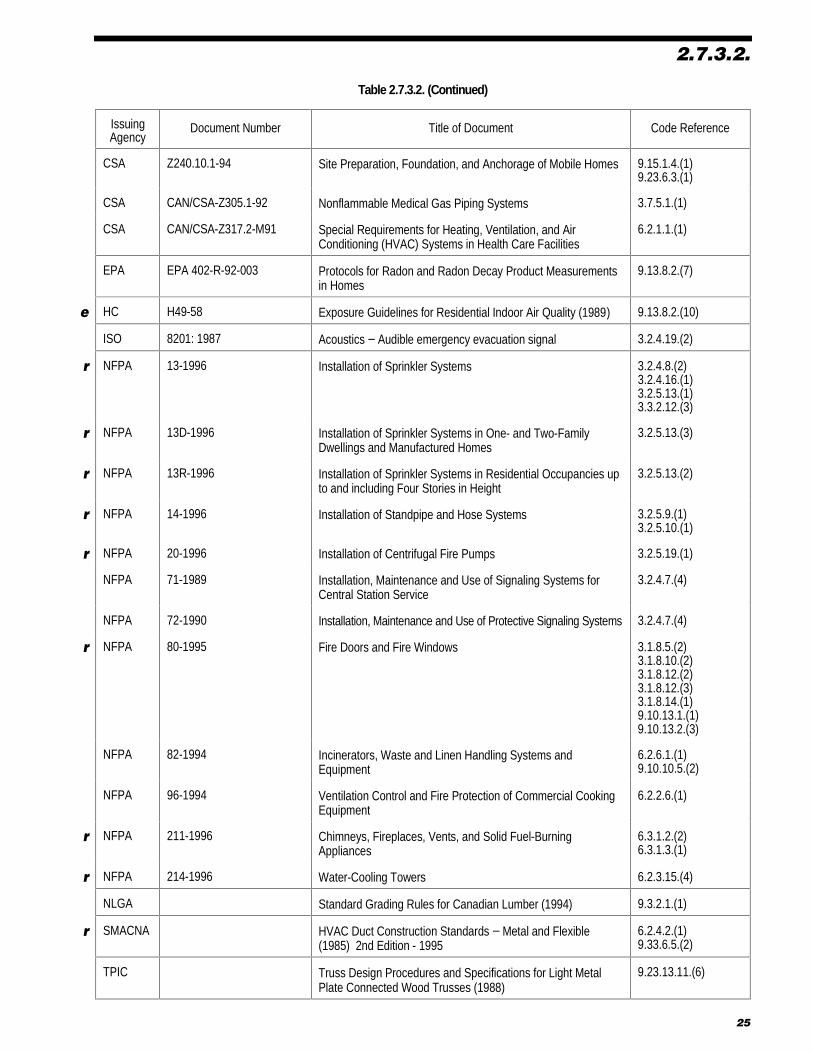
Table 2.7.3.2. (Continued)
IssuingAgency
Document Number Title of Document Code Reference
CSA Z240.10.1-94 Site Preparation, Foundation, and Anchorage of Mobile Homes 9.15.1.4.(1)9.23.6.3.(1)
CSA CAN/CSA-Z305.1-92 Nonflammable Medical Gas Piping Systems 3.7.5.1.(1)
CSA CAN/CSA-Z317.2-M91 Special Requirements for Heating, Ventilation, and AirConditioning (HVAC) Systems in Health Care Facilities
6.2.1.1.(1)
EPA EPA 402-R-92-003 Protocols for Radon and Radon Decay Product Measurementsin Homes
9.13.8.2.(7)
e HC H49-58 Exposure Guidelines for Residential Indoor Air Quality (1989 ) 9.13.8.2.(10)
ISO 8201: 1987 Acoustics − Audible emergency evacuation signal 3.2.4.19.(2)
r NFPA 13-1996 Installation of Sprinkler Systems 3.2.4.8.(2)3.2.4.16.(1)3.2.5.13.(1)3.3.2.12.(3)
r NFPA 13D-1996 Installation of Sprinkler Systems in One- and Two-FamilyDwellings and Manufactured Homes
3.2.5.13.(3)
r NFPA 13R-1996 Installation of Sprinkler Systems in Residential Occupancies upto and including Four Stories in Height
3.2.5.13.(2)
r NFPA 14-1996 Installation of Standpipe and Hose Systems 3.2.5.9.(1)3.2.5.10.(1)
r NFPA 20-1996 Installation of Centrifugal Fire Pumps 3.2.5.19.(1)
NFPA 71-1989 Installation, Maintenance and Use of Signaling Systems forCentral Station Service
3.2.4.7.(4)
NFPA 72-1990 Installation, Maintenance and Use of Protective Signaling Systems 3.2.4.7.(4)
r NFPA 80-1995 Fire Doors and Fire Windows 3.1.8.5.(2)3.1.8.10.(2)3.1.8.12.(2)3.1.8.12.(3)3.1.8.14.(1)9.10.13.1.(1)9.10.13.2.(3)
NFPA 82-1994 Incinerators, Waste and Linen Handling Systems andEquipment
6.2.6.1.(1)9.10.10.5.(2)
NFPA 96-1994 Ventilation Control and Fire Protection of Commercial CookingEquipment
6.2.2.6.(1)
r NFPA 211-1996 Chimneys, Fireplaces, Vents, and Solid Fuel-BurningAppliances
6.3.1.2.(2)6.3.1.3.(1)
r NFPA 214-1996 Water-Cooling Towers 6.2.3.15.(4)
NLGA Standard Grading Rules for Canadian Lumber (1994) 9.3.2.1.(1)
r SMACNA HVAC Duct Construction Standards − Metal and Flexible(1985) 2nd Edition - 1995
6.2.4.2.(1)9.33.6.5.(2)
TPIC Truss Design Procedures and Specifications for Light MetalPlate Connected Wood Trusses (1988)
9.23.13.11.(6)

2.7.3.2.
26
Table 2.7.3.2. (Continued)
IssuingAgency
Document Number Title of Document Code Reference
ULC CAN/ULC-S101-M89 Fire Endurance Tests of Building Construction and Materials 3.1.5.11.(3)3.1.5.11.(4)3.1.5.11.(6)3.1.7.1.(1)3.1.11.7.(1)3.2.3.7.(7)3.2.6.5.(6)
ULC CAN/ULC-S102-M88 Test for Surface Burning Characteristics of Building Materialsand Assemblies
3.1.12.1.(1)
ULC CAN/ULC-S102.2-M88 Test for Surface Burning Characteristics of Flooring, FloorCovering, and Miscellaneous Materials and Assemblies
3.1.12.1.(2)3.1.13.4.(1)
ULC ULC S102.3-M1982 Fire Test of Light Diffusers and Lenses 3.1.13.4.(1)
ULC CAN4-S104-M80 Fire Tests of Door Assemblies 3.1.8.4.(1)3.2.6.5.(3)9.10.13.2.(1)
ULC CAN4-S105-M85 Fire Door Frames Meeting the Performance Required byCAN4-S104
9.10.13.6.(1)
ULC CAN4-S106-M80 Fire Tests of Window and Glass Block Assemblies 3.1.8.4.(1)
ULC CAN/ULC-S107-M87 Fire Tests of Roof Coverings 3.1.15.1.(1)
ULC CAN/ULC-S109-M87 Flame Tests of Flame-Resistant Fabrics and Films 3.1.6.5.(1)3.2.3.20.(1)3.6.5.2.(2)3.6.5.3.(1)9.33.6.3.(1)
ULC CAN/ULC-S110-M86 Fire Tests for Air Ducts 3.6.5.1.(2)3.6.5.1.(5)9.33.6.2.(2)9.33.6.2.(4)
r ULC ULC-S111-95 Fire Tests for Air Filter Units 6.2.3.14.(1)9.33.6.15.(1)
ULC CAN/ULC-S112-M90 Fire Test of Fire Damper Assemblies 3.1.8.4.(1)9.33.6.2.(4)
ULC CAN4-S113-79 Wood Core Doors Meeting the Performance Required byCAN4-S104-77 for Twenty Minute Fire Rated ClosureAssemblies
9.10.13.2.(1)
ULC CAN4-S114-M80 Test for Determination of Non-Combustibility in BuildingMaterials
1.1.3.2.(1)
r ULC ULC-S115-95 Fire Tests for Fire Stop Systems 3.1.5.15.(3)3.1.9.1.(1)3.1.9.1.(2)3.1.9.4.(4)9.10.9.7.(3)
ULC CAN4-S124-M85 Test for the Evaluation of Protective Coverings for FoamedPlastic
3.1.5.11.(2)

2.7.3.2.
27
Table 2.7.3.2. (Continued)
IssuingAgency
Document Number Title of Document Code Reference
ULC CAN/ULC-S126-M86 Test for Fire Spread under Roof-Deck Assemblies 3.1.14.1.(1)3.1.14.2.(1)
ULC CAN/ULC-S134-92 Fire Test of Exterior Wall Assemblies 3.1.5.5.(1)
ULC S505-1974 Fusible Links for Fire Protection Service 3.1.8.9.(1)
ULC CAN/ULC-S524-M91 Installation of Fire Alarm Systems 3.2.4.5.(1)
ULC CAN/ULC-S531-M87 Smoke Alarms 3.2.4.21.(1)9.10.18.1.(1)
r ULC CAN/ULC-S537-97 Verification of Fire Alarm Systems 3.2.4.5.(2)
ULC CAN/ULC-S553-M86 Installation of Smoke Alarms 3.2.4.21.(7)
ULC CAN/ULC-S610-M87 Factory-Built Fireplaces 9.22.8.1.(1)
ULC ULC-S628-93 Fireplace Inserts 9.22.10.1.(1)
ULC CAN/ULC-S629-M87 650°C Factory-Built Chimneys 9.21.1.2.(1)
ULC CAN/ULC-S639-M87 Steel Liner Assemblies for Solid-Fuel Burning MasonryFireplaces
9.22.2.3.(1)
r ULC CAN/ULC-S701-97 Thermal Insulation, Polystyrene, Boards and Pipe Covering 5.3.1.2.(2)Table 9.23.16.2.A.9.25.2.2.(1)9.25.2.2.(4)
r ULC CAN/ULC-S702-97 Thermal Insulation, Mineral Fibre, for Buildings 5.3.1.2.(2)Table 9.23.16.2.A.9.25.2.2.(1)
ULC ULC/ORD-C199P-M1988 Combustible Piping for Sprinkler Systems 3.2.5.14.(2)

28

3.2.2.16.
a) more than 1.8 m high between the lowestpart of the floor assembly and theground or other surface below,
b) used for any occupancy,c) used for the passage of flue pipes, ord) used as a plenum in combustible
construction.
2) A floor assembly immediately above acrawl space is not required to be constructed as a fireseparation and is not required to have a fire-resistancerating provided the crawl space is not required to beconsidered as a basement by Sentence (1).
3.2.2.10. Streets
1) Every building shall face a street locatedin conformance with the requirements of Articles
e 3.2.5.4. and 3.2.5.5. for access routes.
2) For the purposes of Subsections 3.2.2.and 3.2.5. an access route conforming to Subsection3.2.5. is permitted to be considered as a street.
3) A building is considered to face 2 streetsprovided not less than 50% of the building perimeteris located within 15 m of the street or streets.
4) A building is considered to face 3 streetsprovided not less than 75% of the building perimeteris located within 15 m of the street or streets.
5) Enclosed spaces, tunnels, bridges andsimilar structures, even though used for vehicularor pedestrian traffic, are not considered as streets forthe purpose of this Part.
3.2.2.11. Exterior Balconies
1) An exterior balcony shall be constructedin accordance with the type of construction requiredby Articles 3.2.2.20. to 3.2.2.83., as applicable to theoccupancy classification of the building.
3.2.2.12. Exterior Passageways
1) An elevated exterior passageway used aspart of a means of egress shall conform to the require-ments of Articles 3.2.2.20. to 3.2.2.83. for mezzanines.
3.2.2.13. Occupancy on Roof
1) A portion of a roof that supports an occu-pancy shall be constructed in conformance with thefire separation requirements of Articles 3.2.2.20. to3.2.2.83. for floor assemblies, and not the fire-resistance rating for roof assemblies.
3.2.2.14. Roof-Top Enclosures
1) A roof-top enclosure for elevator machin-ery or for a service room shall be constructed inaccordance with the type of construction requiredby Articles 3.2.2.20. to 3.2.2.83.
2) A roof-top enclosure for elevator machin-ery or for a service room, not more than one storeyhigh, is not required to have a fire-resistance rating.
3) A roof-top enclosure for a stairway shallbe constructed in accordance with the type ofconstruction required by Articles 3.2.2.20. to 3.2.2.83.
4) A roof-top enclosure for a stairway neednot have a fire-resistance rating nor be constructed asa fire separation.
3.2.2.15. Storeys below Ground
1) If a building is erected entirely below theadjoining finished ground level and does not extendmore than one storey below that ground level, theminimum precautions against fire spread and col-lapse shall be the same as are required for basementsunder a building of 1 storey in building height havingthe same occupancy and building area.
2) If any portion of a building is erected en-tirely below the adjoining finished ground level andextends more than one storey below that groundlevel, the following minimum precautions againstfire spread and collapse shall be taken:
a) except as permitted by Sentence (3), thebasements shall be sprinklered throughout,
b) a floor assembly below the ground levelshall be constructed as a fire separationwith a fire-resistance rating not less than
i) 3 h if the basements are used asGroup E or Group F, Division 1 or 2occupancies, or
ii) 2 h if the basements are not used asGroup E or Group F, Division 1 or 2occupancies, and
c) all loadbearing walls, columns and archesshall have a fire-resistance rating not lessthan that required for the constructionthat they support.
3) If the first storey of a building is not re-quired to be sprinklered, sprinklers are not requiredin the storey immediately below the first storey pro-vided the storey below
a) contains only residential occupancies, andb) has at least one unobstructed access open-
ing conforming to Sentence 3.2.5.1.(2)installed on that storey for each 15 m ofwall length in at least one wall requiredby this Subsection to face a street.
3.2.2.16. Heavy Timber Roof Permitted
1) Unless otherwise permitted by Articles3.2.2.20. to 3.2.2.83., a roof assembly in a building upto 2 storeys in building height is permitted to be ofheavy timber construction regardless of building areaor type of construction required, provided thebuilding is sprinklered throughout.
53

3.2.2.16.
2) If Sentence (1) permits a roof assembly tobe of heavy timber construction, structural membersin the storey immediately below the roof assemblyare permitted to be of heavy timber construction.
3.2.2.17. Arena Type Building RoofAssembly
1) The requirements for a roof assembly tohave a fire-resistance rating are permitted to bewaived for a gymnasium, a swimming pool, anarena, or a rink if no part of the roof assembly isless than 6 m above the main floor or balcony andthe roof carries no loads other than normal roofloads, including permanent access walks, and venti-lating, sound and lighting equipment, except thatthe restriction concerning minimum distance shallnot apply to
a) an inclined and stepped floor ascendingfrom the main floor which is used forseating purposes only, or
b) a balcony used for seating purposes only.
3.2.2.18. Automatic Sprinkler SystemRequired
1) Except as permitted by Sentence (2), anautomatic sprinkler system conforming to the re-quirements of Articles 3.2.4.7., 3.2.4.8., 3.2.4.9., and3.2.5.13. shall be installed throughout a building reg-ulated by one or more of Articles 3.2.2.20., 3.2.2.21.,3.2.2.22., 3.2.2.23., 3.2.2.24., 3.2.2.26., 3.2.2.27.,3.2.2.29., 3.2.2.31., 3.2.2.33., 3.2.2.36., 3.2.2.37.,3.2.2.38., 3.2.2.39., 3.2.2.40., 3.2.2.41., 3.2.2.42.,3.2.2.43., 3.2.2.45., 3.2.2.48., 3.2.2.49., 3.2.2.51.,3.2.2.52., 3.2.2.54., 3.2.2.56., 3.2.2.57., 3.2.2.58.,3.2.2.60., 3.2.2.62., 3.2.2.63., 3.2.2.64., 3.2.2.65.,3.2.2.67., 3.2.2.68., 3.2.2.70., 3.2.2.72., 3.2.2.73.,3.2.2.75., 3.2.2.77., 3.2.2.79. and 3.2.2.81.
2) If a storey in a building or a floor area isrequired to have an automatic sprinkler system in-stalled throughout in accordance with one or moreof Articles 3.2.2.20. to 3.2.2.83. or Section 3.3., theautomatic sprinkler system shall also be installedthroughout all lower storeys in the building notwith-standing permission in Articles 3.2.2.20. to 3.2.2.83.to construct one or more of those storeys without in-stalling automatic sprinkler protection. (SeeAppendix A.)
3.2.2.19. Buildings Containing ImpededEgress Zones
1) A building containing an impeded egresszone and conforming to the appropriate require-ments of Articles 3.2.2.20. to 3.2.2.83. is not requiredto conform to the requirements of Articles 3.2.2.36.and 3.2.2.37. for a Group B, Division 1 major occu-pancy provided
a) the building is sprinklered throughout,
b) it is not more than 1 storey in buildingheight,
c) it does not includei) a contained use area,
ii) sleeping accommodation,iii) a high hazard industrial occupancy, oriv) a mercantile occupancy,
d) the building area is not more than6 400 m2 if the building includes a mediumhazard industrial occupancy,
e) the impeded egress zone does not extendbeyond the boundaries of the fire compart-ment in which it is located, and
f) the occupant load of the impeded egress zoneis not more than 100.
3.2.2.20. Group A, Division 1, Any Height,Any Area, Sprinklered
1) Except as permitted by Articles 3.2.2.21.and 3.2.2.22., a building classified as Group A,Division 1 shall conform to Sentence (2).
2) Except as permitted by Article 3.2.2.16.,the building referred to in Sentence (1) shall be ofnoncombustible construction, and
a) except as permitted by Sentences3.2.2.7.(1) and 3.2.2.18.(2), the buildingshall be sprinklered throughout,
b) floor assemblies shall be fire separationswith a fire-resistance rating not less than2 h,
c) mezzanines shall have a fire-resistancerating not less than 1 h, and
d) loadbearing walls, columns and archesshall have a fire-resistance rating not lessthan that required for the supportedassembly.
3.2.2.21. Group A, Division 1, One Storey,Limited Area, Sprinklered
1) A building classified as Group A, Division1 is permitted to conform to Sentence (2) provided
a) except as permitted by Sentences3.2.2.7.(1) and 3.2.2.18.(2), the building issprinklered throughout,
b) it is not more than 1 storey in buildingheight,
c) it has less than 40% of the area of thebuilding as 2 storeys for the purpose of
i) development of productions, includ-ing preparation of scenery andcostumes and rehearsal of perform-ers,
ii) organization of performers, sceneryand sound equipment,
iii) preparation by performers for a per-formance,
iv) managerial functions, orv) toilets, rest rooms and similar pub-
lic facilities,
54

3.2.2.69.
have a fire-resistance rating not less than45 min, and
b) loadbearing walls, columns and archessupporting an assembly required to havea fire-resistance rating shall
i) have a fire-resistance rating not lessthan 45 min, or
ii) be of noncombustible construction.
3.2.2.66. Group F, Division 1, One Storey
1) A building classified as Group F, Division1 is permitted to be of combustible construction ornoncombustible construction used singly or in combi-nation provided
a) it is not more than 1 storey in buildingheight, and
b) it has a building area not more than800 m2.
3.2.2.67. Group F, Division 2, Any Height,Any Area, Sprinklered
1) Except as permitted by Articles 3.2.2.68.to 3.2.2.72., a building classified as Group F, Division2 shall conform to Sentence (2).
2) Except as permitted by Article 3.2.2.16.,the building referred to in Sentence (1) shall be ofnoncombustible construction, and
a) except as permitted by Sentences3.2.2.7.(1) and 3.2.2.18.(2), the buildingshall be sprinklered throughout,
b) floor assemblies shall be fire separationswith a fire-resistance rating not less than2 h,
c) mezzanines shall have a fire-resistancerating not less than 1 h, and
d) loadbearing walls, columns and archesshall have a fire-resistance rating not lessthan that required for the supportedassembly.
3.2.2.68. Group F, Division 2, up to 4Storeys, Increased Area,Sprinklered
1) A building classified as Group F, Division2 is permitted to conform to Sentence (2) provided
a) except as permitted by Sentences3.2.2.7.(1) and 3.2.2.18.(2), the building issprinklered throughout,
b) it is not more than 4 storeys in buildingheight, and
c) it has a building area not more thani) 18 000 m2 if 1 storey in building
height,ii) 9 000 m2 if 2 storeys in building
height,iii) 6 000 m2 if 3 storeys in building
height, or
iv) 4 500 m2 if 4 storeys in buildingheight.
2) Except as permitted by Article 3.2.2.16.,the building referred to in Sentence (1) shall be ofnoncombustible construction, and
a) floor assemblies shall be fire separationswith a fire-resistance rating not less than1 h,
b) mezzanines shall have a fire-resistancerating not less than 1 h, and
c) loadbearing walls, columns and archesshall have a fire-resistance rating not lessthan that required for the supportedassembly.
3.2.2.69. Group F, Division 2, up to 3Storeys
1) A building classified as Group F, Division2 is permitted to conform to Sentence (2) provided
a) it is not more than 3 storeys in buildingheight, and
b) it has a building area not more than thevalue in Table 3.2.2.69.
Table 3.2.2.69.Maximum Building Area, Group F, Division 2, up to 3
StoreysForming Part of Sentence 3.2.2.69.(1)
Maximum Area, m2
No. ofStoreys Facing
1 StreetFacing
2 StreetsFacing
3 Streets
1 1 500 1 500 1 5002 1 500 1 500 1 5003 1 070 1 340 1 500
2) The building referred to in Sentence (1) ispermitted to be of combustible construction ornoncombustible construction used singly or in combi-nation, and
a) floor assemblies shall be fire separationswith a fire-resistance rating not less than45 min,
b) mezzanines shall have, if of combustibleconstruction, a fire-resistance rating not lessthan 45 min,
c) roof assemblies shall have, if of com-bustible construction, a fire-resistance ratingnot less than 45 min, except that in abuilding not more than 1 storey in buildingheight, the fire-resistance rating is permit-ted to be waived provided that the roofassembly is constructed as a fire-retardanttreated wood roof system conforming toArticle 3.1.14.1.,
67

3.2.2.69.
d) loadbearing walls, columns and archessupporting an assembly required to havea fire-resistance rating shall
i) have a fire-resistance rating not lessthan 45 min, or
ii) be of noncombustible construction, ande) loadbearing walls, columns and arches
supporting a fire separation shall have afire-resistance rating not less than that re-quired for the fire separation.
3.2.2.70. Group F, Division 2, up to 4Storeys, Sprinklered
1) A building classified as Group F, Division2 is permitted to conform to Sentence (2) provided
a) except as permitted by Sentences3.2.2.7.(1) and 3.2.2.18.(2), the building issprinklered throughout,
b) it is not more than 4 storeys in buildingheight, and
c) it has a building area not more thani) 9 600 m2 if 1 storey in building height,
ii) 4 800 m2 if 2 storeys in buildingheight,
iii) 3 200 m2 if 3 storeys in buildingheight, or
iv) 2 400 m2 if 4 storeys in buildingheight.
2) The building referred to in Sentence (1) ispermitted to be of combustible construction ornoncombustible construction used singly or in combi-nation, and
a) floor assemblies shall be fire separationswith a fire-resistance rating not less than45 min,
b) mezzanines shall have, if of combustibleconstruction, a fire-resistance rating not lessthan 45 min,
c) loadbearing walls, columns and archessupporting an assembly required to havea fire-resistance rating shall
i) have a fire-resistance rating not lessthan 45 min, or
ii) be of noncombustible construction, andd) loadbearing walls, columns and arches
supporting a fire separation shall have afire-resistance rating not less than that re-quired for the fire separation.
3.2.2.71. Group F, Division 2, up to 2Storeys
1) A building classified as Group F, Division2 is permitted to conform to Sentence (2) provided
a) it is not more than 2 storeys in buildingheight, and
b) it has a building area not more than thevalue in Table 3.2.2.71.
Table 3.2.2.71.Maximum Building Area, Group F, Division 2, up to 2 e
StoreysForming Part of Sentence 3.2.2.71.(1)
Maximum Area, m2
No. ofStoreys Facing
1 StreetFacing
2 StreetsFacing
3 Streets
1 1 000 1 250 1 5002 600 750 900
2) The building referred to in Sentence (1) ispermitted to be of combustible construction ornoncombustible construction used singly or in combi-nation, and
a) floor assemblies shall be fire separationsand, if of combustible construction, shallhave a fire-resistance rating not less than45 min, and
b) loadbearing walls, columns and archessupporting an assembly required to havea fire-resistance rating shall
i) have a fire-resistance rating not lessthan 45 min, or
ii) be of noncombustible construction.
3.2.2.72. Group F, Division 2, up to 2Storeys, Sprinklered
1) A building classified as Group F, Division2 is permitted to conform to Sentence (2) provided
a) except as permitted by Sentences3.2.2.7.(1) and 3.2.2.18.(2), the building issprinklered throughout,
b) it is not more than 2 storeys in buildingheight, and
c) it has a building area not more thani) 4 500 m2 if 1 storey in building height,
orii) 1 800 m2 if 2 storeys in building
height.
2) The building referred to in Sentence (1) ispermitted to be of combustible construction ornoncombustible construction used singly or in combi-nation, and
a) floor assemblies shall be fire separationsand, if of combustible construction, shallhave a fire-resistance rating not less than45 min, and
b) loadbearing walls, columns and archessupporting an assembly required to havea fire-resistance rating shall
i) have a fire-resistance rating not lessthan 45 min, or
ii) be of noncombustible construction.
68

3.2.3.1.
3.2.2.79. Group F, Division 3, up to 2Storeys, Sprinklered
1) A building classified as Group F, Division3 is permitted to conform to Sentence (2) provided
a) except as permitted by Sentences3.2.2.7.(1) and 3.2.2.18.(2), the building issprinklered throughout,
b) it is not more than 2 storeys in buildingheight, and
c) it has a building area not more thani) 7 200 m2 if 1 storey in building height,
orii) 2 400 m2 if 2 storeys in building
height.
2) The building referred to in Sentence (1) ispermitted to be of combustible construction ornoncombustible construction used singly or in combi-nation, and
a) floor assemblies shall be fire separationsand, if of combustible construction, shallhave a fire-resistance rating not less than45 min, and
b) loadbearing walls, columns and archessupporting an assembly required to havea fire-resistance rating shall
i) have a fire-resistance rating not lessthan 45 min, or
ii) be of noncombustible construction.
3.2.2.80. Group F, Division 3, One Storey
1) A building classified as Group F, Division3 is permitted to be of heavy timber construction ornoncombustible construction used singly or in combi-nation provided
a) it is not more than 1 storey in buildingheight, and
b) it has a building area not more thani) 5 600 m2 if facing one street,
ii) 7 000 m2 if facing 2 streets, oriii) 8 400 m2 if facing 3 streets.
3.2.2.81. Group F, Division 3, One Storey,Sprinklered
1) A building classified as Group F, Division3 is permitted to be of heavy timber construction ornoncombustible construction used singly or in combi-nation provided
a) except as permitted by Sentences3.2.2.7.(1) and 3.2.2.18.(2), the building issprinklered throughout,
b) it is not more than 1 storey in buildingheight, and
c) it has a building area not more than16 800 m2.
3.2.2.82. Group F, Division 3, One Storey,Any Area, Low Fire LoadOccupancy
1) A building classified as Group F, Division3 is permitted to conform to Sentence (2) providedit is
a) not more than 1 storey in building height,b) used solely for low fire load occupancies
such asi) power generating plants, or
ii) plants for the manufacture or stor-age of noncombustible materials, and
c) not limited in building area.
2) The building referred to in Sentence (1)shall be of noncombustible construction.
3.2.2.83. Group F, Division 3, StorageGarages up to 22 m High
1) A building used as a storage garage withall storeys constructed as open-air storeys and havingno other occupancy above it is permitted to have itsfloor, wall, ceiling and roof assemblies constructedwithout a fire-resistance rating provided it is
a) of noncombustible construction,b) not more than 22 m high, measured be-
tween grade and the ceiling level of thetop storey,
c) not more than 10 000 m2 in building area,and
d) designed so that every portion of eachfloor area is within 60 m of an exteriorwall opening.
3.2.3. Spatial Separation andExposure Protection
3.2.3.1. Limiting Distance and Area ofUnprotected Openings
1) Except as permitted by Articles 3.2.3.9. to3.2.3.11., the area of unprotected openings in an expos-ing building face for the applicable limiting distanceshall be not more than the value determined in ac-cordance with
a) Table 3.2.3.1.A. or Table 3.2.3.1.B. for anexposing building face conforming toArticle 3.2.3.2. of a building or fire com-partment which is not sprinklered, or
b) Table 3.2.3.1.C. or Table 3.2.3.1.D. for anexposing building face conforming toArticle 3.2.3.2. of a sprinklered fire compart-ment that is part of a building which issprinklered in conformance with Section3.2.
(See A-3, Fire Fighting Assumptions, in AppendixA.) (See also Article 3.1.6.3.)
2) The area of the unprotected openings in anexposing building face shall be the aggregate area of
71

3.2.3.1.
72--
unprotected openings expressed as a percentage of thearea of the exposing building face in Table 3.2.3.1.A.,Table 3.2.3.1.B., Table 3.2.3.1.C. or Table 3.2.3.1.D.(See Sentence 3.2.3.2.(1).)
3) For the purpose of determining the typeof construction and cladding and the fire-resistancerating of an exterior wall,
a) the exposing building face shall be taken asthe projection of the exterior wall onto avertical plane located so that no portionof the exterior wall of the building or of afire compartment, if the fire compartmentcomplies with the requirements ofSentences 3.2.3.2.(2), (4) or (6), is betweenthe vertical plane and the line to whichthe limiting distance is measured, and
b) the area of unprotected openings shall bedetermined from Table 3.2.3.1.A., Table3.2.3.1.B., Table 3.2.3.1.C. or Table3.2.3.1.D.
4) For the purpose of determining the actualpercentage of unprotected openings permitted in anexterior wall, the location of the exposing buildingface is permitted to be taken at a vertical planelocated so that there are no unprotected openings be-tween the vertical plane and the line to which thelimiting distance is measured. (See Appendix A.)
5) If a building has any storey that is notsprinklered and fire fighting facilities cannot reach itwithin 10 min of the alarm being received, the limit-ing distance shall be doubled.
6) If the surface temperature on the unex-posed surface of a wall assembly exceeds thetemperature limit of a standard fire test as permit-ted by Article 3.1.7.2., an allowance shall be madefor the radiation from the hot unexposed wall sur-face by adding an equivalent area of unprotectedopening to the area of actual openings as follows:
)F (A A cA O E F ×+=
where
AC = corrected area of unprotected openings in-cluding actual and equivalent openings,
A = actual area of unprotected openings,AF = area of exterior surface of the exposing
building face, exclusive of openings, onwhich the temperature limit of the stan-dard test is exceeded, and
FEO = an equivalent opening factor derivedfrom the following expression:
4
e
4u
EO273) (T
273) (T F
++
=
Tu = average temperature in degrees Celsiusof the unexposed wall surface at thetime the required fire-resistance rating isreached under test conditions,
Te = 892°C for a fire-resistance rating not lessthan 45 min, 927°C for a fire-resistancerating not less than 1 h, and 1 010°C fora fire-resistance rating not less than 2 h.
7) Unless a closure used to protect an open-ing in an exposing building face has a protectiveperformance equivalent to that required for the wallassembly in which it is located, an equivalent areaof unprotected opening, determined in accordancewith the procedures of Sentence (6) shall be addedto the greater of
a) the actual area of unprotected openings, orb) the corrected area of unprotected openings.
e

3.2.8.6.
with the requirements of Articles 3.2.8.3. to 3.2.8.9.provided the mezzanine
a) serves a Group A, Division 1 major occu-pancy,
b) serves a Group A, Division 3 major occu-pancy in a building not more than 2 storeysin building height, or
c) serves a Group A, C, D, E or F majoroccupancy and
i) is 500 m2 or less in area,ii) has an aggregate area not more
than 40% of the storey in which it islocated,
iii) is not subdivided by partitions orwalls if the mezzanine is more than10% of the area of the storey inwhich it is located, and
iv) has no visual obstruction, except foropen bookshelves, more than1 070 mm above the floor of themezzanine or above the floor of thespace below it if the mezzanine ismore than 10% of the area of thestorey in which it is located.
2) Except for floors referred to in Sentence3.1.10.3.(1) and Article 3.2.1.2., openings through ahorizontal fire separation for vehicular ramps in astorage garage are not required to be protected withclosures and need not conform to this Subsection.
3) If a closure in an opening in a fire separa-tion would disrupt the nature of a manufacturingprocess, such as a continuous flow of material fromstorey to storey, the closure for the opening is permit-ted to be omitted provided precautions are taken tooffset the resulting hazard. (See Appendix A.)
4) An interconnected floor space in a Group B,Division 1 occupancy need not conform to the re-quirements of Articles 3.2.8.3. to 3.2.8.9. providedthe interconnected floor space does not interconnectmore than 2 adjacent storeys.
5) Except as permitted by Sentence (6),openings for escalators and inclined moving walksneed not conform to the requirements in Articles3.2.8.3. to 3.2.8.9 provided
a) the opening for each escalator or walkdoes not exceed 10 m2,
b) the building is sprinklered throughout, andc) the interconnected floor space contains only
Group A, Division 1, 2 or 3, Group D orGroup E major occupancies. (See A-3.2.8.2.(6)(c) in Appendix A.)
6) An interconnected floor space need not con-form to the requirements of Articles 3.2.8.3. to3.2.8.9. provided
a) the interconnected floor space consists ofthe first storey and the storey next aboveor below it, but not both,
b) the openings through the floor are usedonly for stairways, escalators or movingwalks or the interconnected floor space issprinklered throughout (see Appendix A),
c) the interconnected floor space contains onlyGroup A, Division 1, 2 or 3, Group D,Group E or Group F, Division 3 majoroccupancies (see Appendix A), and
d) the building area is not more than one halfof the area permitted by Subsection 3.2.2.
3.2.8.3. Construction Requirements
1) A building constructed in conformancewith Articles 3.2.8.4. to 3.2.8.9. shall be of noncom-bustible construction, except that heavy timberconstruction is permitted if Subsection 3.2.2. permitsthe building to be constructed of combustibleconstruction.
3.2.8.4. Sprinklers
1) A building containing an interconnectedfloor space shall be sprinklered throughout.
3.2.8.5. Vestibules
1) An exit opening into an interconnectedfloor space shall be protected at each opening intothe interconnected floor space by a vestibule
a) with doorways that are not less than1.8 m apart,
b) which is separated from the remainder ofthe floor area by a fire separation which isnot required to have a fire-resistance rating(see A-3.1.8.1.(1)(b) in Appendix A), and
c) which is designed to limit the passage ofsmoke so that the level of contaminationin an exit stair shaft does not exceed thelimit described in Sentence 3.2.6.2.(2).
2) An exit opening into an interconnectedfloor space shall conform to Sentence 3.4.3.3.(2).
3) If an elevator hoistway opens into an in-terconnected floor space and into storeys above theinterconnected floor space, either the elevator doorsopening into the interconnected floor space or theelevator doors opening into the storeys above the in-terconnected floor space shall be protected byvestibules conforming to Sentence (1).
3.2.8.6. Protected Floor Space
1) For the purposes of this Subsection, theterm protected floor space applies to that part of afloor area separated from the interconnected floor spaceby a fire separation having a fire-resistance rating notless than that required for the floor assembly of thestorey in which it is located and in which openingsthrough the vertical fire separation are protected byvestibules conforming to Sentence 3.2.8.5.(1).
95

3.2.8.6.
96--
2) A protected floor space as defined inSentence (1) shall be designed so that it is not neces-sary to enter the interconnected floor space to reach anexit.
3.2.8.7. Draft Stops
1) A draft stop shall be provided at eachfloor level within an interconnected floor space, imme-diately adjacent to and surrounding the opening,and shall be not less than 500 mm deep measuredfrom ceiling level down to the underside of thedraft stop.
3.2.8.8. Mechanical Exhaust System
1) A mechanical exhaust system shall beprovided to remove air from an interconnected floorspace at a rate of 4 air changes per hour. (SeeAppendix A.)
2) The mechanical exhaust system requiredby Sentence (1) shall be actuated by a switch locatedon the storey containing the entrance for fire fighteraccess referred to in Articles 3.2.5.4 and 3.2.5.5. nearthe annunciator for the fire alarm system.
3.2.8.9. Combustible Content Limits
1) An interconnected floor space shall be de-signed so that the combustible contents, excludinginterior finishes, in those parts of a floor area inwhich the ceiling is more than 8 m above the floor,are limited to not more than 16 g of combustiblematerial for each cubic metre of volume of the inter-connected floor space.
Section 3.3. Safetywithin Floor Areas(See Appendix A.)
3.3.1. All Floor Areas
3.3.1.1. Separation of Suites
1) Except as permitted by Sentences (2) and(3), each suite in other than business and personal ser-vices occupancies shall be separated from adjoiningsuites by a fire separation having a fire-resistance ratingnot less than 1 h. (See also Subsection 3.3.3. for careor detention occupancies, Article 3.3.4.2. for residentialoccupancies and Article 3.1.8.7. for fire dampers.)
2) The fire-resistance rating of the fire separa-tion required by Sentence (1) is permitted to be lessthan 1 h but not less than 45 min provided the fire-resistance rating required by Subsection 3.2.2. ispermitted to be less than 1 h for
a) the floor assembly above the floor area, or
b) the floor assembly below the floor area, ifthere is no floor assembly above.
3) Occupancies that are served by public cor-ridors conforming to Sentence 3.3.1.4.(4) in a building ethat is sprinklered throughout, are not required to beseparated from one another by fire separations pro-vided the occupancies are
a) suites of business and personal services occu-pancy,
b) fast food vending operations that do notprovide seating for customers,
c) suites of mercantile occupancy, ord) any combination of these occupancies.
3.3.1.2. Hazardous Substances,Equipment and Processes
1) If hazardous substances are used in con-nection with the activities of any occupancy otherthan as permitted by Subsection 3.3.5. for a high haz-ard industrial occupancy, the storage, handling anduse of the hazardous substances shall be in confor-mance with
a) provincial, territorial or municipal regula-tions, or
b) the National Fire Code of Canada 1995,in the absence of regulations referred toin Clause (a).
(See Appendix A.)
2) Cooking equipment, not within a dwellingunit, used in processes producing grease-ladenvapours shall be designed and installed in confor-mance with Part 6. (See Appendix A.)
3) A fuel-fired appliance shall not be in-stalled in a corridor serving as an access to exit.
3.3.1.3. Means of Egress
1) Access to exit within floor areas shall con-form to Subsections 3.3.2. to 3.3.5., in addition to therequirements of this Subsection.
2) If a podium, terrace, platform or con-tained open space is provided, egress requirementsshall conform to the appropriate requirements ofSentence 3.3.1.5.(1) for rooms and suites.
3) Means of egress shall be provided fromevery roof which is intended for occupancy, andfrom every podium, terrace, platform or containedopen space.
4) If a roof is used or intended for an occu-pant load more than 60, at least 2 separate means ofegress shall be provided from the roof to stairs,
a) designed in conformance with the re-quirements for exit stairs, and
b) located so that the distance between thestairs conforms to the requirements ofArticle 3.4.2.3. for exits.
e
e

3.3.1.24.
door is readily apparent, by attaching non-transparent hardware, bars or other permanentfixtures to it.
2) A glass door shall be constructed ofa) laminated or tempered safety glass
conforming to CAN/CGSB-12.1-M, “Tem-pered or Laminated Safety Glass,” or
b) wired glass conforming to CAN/CGSB-12.11-M, “Wired Safety Glass.”
3) Except as permitted by Sentence (4),transparent panels used in an access to exit which,because of their physical configuration or design,could be mistaken as a means of egress shall be madeinaccessible by barriers or railings.
4) Sliding glass partitions which separate apublic corridor from an adjacent occupancy and whichare open during normal working hours need notconform to Sentences (1) and (3), provided the parti-tions are suitably marked to indicate their existenceand position.
5) Glass in doors and in sidelights thatcould be mistaken for doors, within or at the en-trances to dwelling units and in public areas, shallconform to the requirements of Article 9.6.6.2.
6) A window in a public area that extendsto less than 1 000 mm above the floor and is locatedabove the second storey in a building of residentialoccupancy, shall be protected by a barrier or railingto not less than 1 070 mm above the floor, or thewindow shall be non-openable and designed towithstand the lateral design loads for balconyguards required by Article 4.1.10.1.
3.3.1.19. Exhaust Ventilation
1) An exhaust ventilation system designedin conformance with the appropriate requirementsof Part 6 shall be provided in a building or part of abuilding in which dust, fumes, gases, vapour orother impurities or contaminants have the potentialto create a fire or explosion hazard. (See also Article4.2.4.15.)
2) Explosion relief devices, vents or otherprotective measures conforming to Subsection 6.2.2.shall be provided for a space in which substances orconditions that have the potential to create anexplosion hazard are present as a result of the prin-cipal use of a building.
3.3.1.20. Janitors’ Rooms
1) Except as permitted by Sentences (2) and(3), a room or space within a floor area for the stor-age of janitorial supplies shall be separated from theremainder of the building by a fire separation havinga fire-resistance rating not less than 1 h.
2) The fire-resistance rating of the fire separa-tion required by Sentence (1) is permitted to be less
than 1 h but not less than 45 min provided the fire-resistance rating required by Subsection 3.2.2. ispermitted to be less than 1 h for
a) the floor assembly above the floor area, orb) the floor assembly below the floor area, if
there is no floor assembly above.
3) The fire separation required by Sentence(1) is not required to have a fire-resistance rating ifthe floor area in which the room or space is locatedis sprinklered throughout.
3.3.1.21. Common Laundry Rooms
1) Except as permitted by Sentences (2) and(3), in a building of residential occupancy, a laundryroom in a floor area that is not within a dwelling unitshall be separated from the remainder of thebuilding by a fire separation having a fire-resistancerating not less than 1 h.
2) The fire-resistance rating of the fire separa-tion required by Sentence (1) is permitted to be lessthan 1 h but not less than 45 min provided the fire-resistance rating required by Subsection 3.2.2. ispermitted to be less than 1 h for
a) the floor assembly above the floor area, orb) the floor assembly below the floor area, if
there is no floor assembly above.
3) The fire separation required by Sentence(1) is not required to have a fire-resistance rating ifthe floor area in which the laundry room is located issprinklered throughout.
3.3.1.22. Obstructions
1) No obstruction shall be permitted in anyoccupancy that would restrict the width of a normalmeans of egress from any part of a floor area to lessthan 750 mm unless an alternative means of egress isprovided adjacent to, accessible from, and plainlyvisible from the obstructed means of egress. (SeeAppendix A.)
3.3.1.23. Signs in Service Spaces
1) Illuminated signs conforming toSentences 3.4.5.1.(3) and (5) shall be provided to in-dicate the direction to egress points in a service spacereferred to in Sentence 3.2.1.1.(7).
3.3.1.24. Welding and Cutting
1) If a room in other than an industrialmajor occupancy is used for welding and cutting op-erations, it shall be separated from the remainder ofthe building by a fire separation having a fire-resistancerating not less than 1 h, except that this requirementdoes not apply to a room that is protected by an au-tomatic fire extinguishing system.
101

3.3.2.
3.3.2. Assembly Occupancy
3.3.2.1. Scope
1) This Subsection applies to floor areas orparts thereof used or intended for use as assemblyoccupancies.
3.3.2.2. Fire Separations
1) Except as permitted by Sentence (2), theseating area of a Group A, Division 1 occupancyshall be separated from adjacent occupancies in thefloor area by a fire separation having a fire-resistancerating not less than 1 h if the occupant load in theseating area exceeds 200.
2) The fire-resistance rating of the fire separa-tion required by Sentence (1) is permitted to be lessthan 1 h but not less than 45 min provided the fire-resistance rating required by Subsection 3.2.2. ispermitted to be less than 1 h for
a) the floor assembly above the floor area, orb) the floor assembly below the floor area, if
there is no floor assembly above.
3) If usable space exists under tiers of seatsin arena type buildings, a fire separation with a fire-resistance rating not less than 45 min shall beprovided between the space and the seats or thespace shall be sprinklered.
3.3.2.3. Fixed Seats
1) Except for the requirements of Article3.3.2.7. for bench-type seats and except as requiredor permitted by Sentence (2) and Articles 3.3.2.9. and3.3.2.10., fixed seats in places of assembly shall be
a) attached or secured to the floor, platformor platform riser,
b) provided with arms and back, andc) arranged in rows having an unobstructed
passage not less than 400 mm wide mea-sured horizontally between plumb linesfrom the backs of the seats in one rowand the edges of the furthest forwardprojection of the seats in the next row inthe unoccupied position.
2) For fixed seats with backs and with fold-ing tablet arms, the value of 400 mm required byClause (1)(c) shall be measured when the tabletarms are in the use position, but is permitted to bemeasured in the stored position provided
a) there are not more than 7 seats betweenany seat and the nearest aisle,
b) the seats are located in a lecture hall oran auditorium used for instructional pur-poses, and
c) the tablet arm, when raised manually toa vertical position, falls by the force ofgravity to the stored position.
(See Appendix A.)
3) Except as permitted by Sentence (4),aisles shall be located so that there are not morethan 7 seats with backs or 20 seats without backsbetween any seat and the nearest aisle.
4) The requirements of Sentence (3) do notapply if
a) egress doorways are provided to serveboth ends of rows of seats,
b) each doorway referred to in Clause (a)serves not more than 3 rows of seats, and
c) each row contains not more than 100seats.
3.3.2.4. Aisles
1) Except as required by Articles 3.3.2.9. eand 3.3.2.10., aisles leading to exits shall beprovided in conformance with Sentences (2) to (17)in places of assembly which contain fixed seats.
2) The minimum clear width of aisles shallbe not less than 1 100 mm, except that the width ispermitted to be reduced to not less than
a) 750 mm if serving not more than 60seats, and
b) 900 mm if serving seats on one side only.
3) Except in the case of bleacher seats, theminimum clear width of aisles referred to inSentence (2) shall be measured at the point farthestfrom an exit, cross aisle or foyer and shall beincreased by 25 mm for each metre of distance to-ward the exit, cross aisle or foyer.
4) Aisles shall terminate in a cross aisle,foyer or exit, and the width of the cross aisle, foyeror exit shall be not less than the required width ofthe widest aisle plus 50% of the total required widthof the remaining aisles that it serves.
5) Dead-end aisles shall be not more than6 m long.
6) The length of travel to an exit door byany aisle shall be not more than 45 m.
7) Side aisles shall be not less than1 100 mm wide if seating is provided in confor-mance with Sentence 3.3.2.3.(4).
8) An aisle that has a slope not more than 1in 8 shall not be stepped.
9) An aisle that slopes more than 1 in 8shall be stepped.
10) The passageway between rows of seatsserved by a stepped aisle shall be level at right an-gles to the line of travel.
11) The riser of a step in an aisle shall bea) not less than 110 mm high, andb) not more than 200 mm high.
12) Variations are permitted in riser heightprovided
102

3.4.4.3.
3) The required width of means of egressserving a Group A, Division 4 occupancy shall be de-termined by multiplying the occupant load of thearea served by
a) 1.8 mm per person fori) aisles,
ii) stairs other than exit stairs, andiii) ramps and passageways in vomito-
ries and exits, andb) 2.4 mm per person for exit stairs.
3.4.3.5. Exit Width Reduction
1) Except as permitted by Sentences (2) to(4), no fixture, turnstile or construction shall projectinto or be fixed within the required width of an exit.
2) Exit doors shall be hung so that, whenopen, they shall neither diminish nor obstruct therequired width of the exit by more than 50 mm foreach door leaf.
3) Swinging doors in their swing shall notreduce the required width of exit stairs or landingsto less than 750 mm or reduce the width of an exitpassageway to less than the minimum requiredwidth.
4) Handrails and construction belowhandrails are permitted to project into the requiredwidth of means of egress but the projections shall benot more than 100 mm on each side of the requiredwidth.
3.4.3.6. Headroom Clearance
1) Except as permitted by Sentences (2) to(4), every exit shall have a headroom clearance ofnot less than 2 100 mm.
2) The headroom clearance for stairwaysmeasured vertically above any landing or the nosingof any stair tread shall be not less than 2 050 mm.
3) The headroom clearance for doorwaysshall be not less than 2 030 mm.
4) No door closer or other device shall beinstalled so as to reduce the headroom clearance ofa doorway to less than 1 980 mm.
3.4.4. Fire Separation of Exits
3.4.4.1. Fire-Resistance Rating of ExitSeparations
1) Except as permitted by Sentences (2),3.3.5.4.(3), 3.4.4.2.(2) and 3.4.4.3.(1), every exit shallbe separated from the remainder of the building by afire separation having a fire-resistance rating not lessthan that required by Subsection 3.2.2., but not lessthan 45 min, for
a) the floor assembly above the storey, orb) the floor assembly below the storey, if
there is no floor assembly above.
2) The fire-resistance rating of the fire separa-tion referred to in Sentence (1) need not be morethan 2 h.
3) If an exit stair in an assembly hall or the-atre serves more than one balcony level, the exitstair shall be separated from the remainder of thebuilding in conformance with Sentence (1).
3.4.4.2. Exits through Lobbies
1) Except as permitted by Sentence (2), noexit from a floor area above or below the first storeyshall lead through a lobby.
2) Not more than one exit from a floor area ispermitted to lead through a lobby provided
a) the lobby floor is not more than 4.5 mabove grade,
b) the path of travel through the lobby tothe outdoors is not more than 15 m,
c) the adjacent rooms or premises havingdirect access to the lobby do not containa residential occupancy or an industrialoccupancy,
d) the lobby is not located within aninterconnected floor space other than as de-scribed in Sentence 3.2.8.2.(6),
e) the lobby conforms to the requirementsfor exits, except that
i) rooms other than service rooms andstorage rooms are permitted to openonto the lobby,
ii) the fire separation between the lobbyand a room used for the sole pur-pose of control and supervision ofthe building need not have a fire-resistance rating, and
iii) the fire separation between the lobbyand adjacent occupancies that arepermitted to open onto the lobbyneed not have a fire-resistance ratingprovided the lobby and adjacentoccupancies are sprinklered, and
(see Appendix A)f) a fire separation, constructed in accordance
with Sentence 3.4.4.1.(1), is maintainedbetween the lobby and any exit permittedby this Sentence to lead through thelobby.
3.4.4.3. Exterior Passageway Exceptions
1) The requirements of Sentences 3.4.4.1.(1)and 3.2.3.12.(1) and (3) do not apply to an exteriorexit passageway provided
a) not less than 50% of the exterior side isopen to the outdoors, and
b) an exit stair is provided at each end ofthe passageway.
113

3.4.4.4.
114
3.4.4.4. Integrity of Exits
1) A fire separation that separates an exitfrom the remainder of the building shall have noopenings except for
a) standpipe and sprinkler piping,b) electrical wires and cables, totally en-
closed noncombustible raceways andnoncombustible piping that serve only theexit,
c) openings required by the provisions ofSubsection 3.2.6.,
d) exit doorways, ande) wired glass and glass block permitted by
Article 3.1.8.14.
2) Exits within scissors stairs and other con-tiguous exit stairways shall be separated from eachother by a smoke-tight fire separation having a fire-resistance rating not less than that required for thefloor assembly through which they pass.
3) Fire separations separating contiguousstairs described in Sentence (2) shall not be piercedby doorways, ductwork, piping or any other open-ings that affect the continuity of the separation.
4) A fuel-fired appliance shall not be in-stalled in an exit.
5) An exit shall not be used as a plenum fora heating, ventilating or air-conditioning system.
6) An exit shall be designed for no purposeother than for exiting, except that an exit is permit-ted also to be designed to serve as an access to afloor area.
7) A service room shall not open directly intoan exit.
8) Storage rooms, washrooms, toilet rooms,laundry rooms and similar ancillary rooms shall notopen directly into an exit.
9) Service spaces referred to in Sentence3.2.1.1.(7) shall not open directly into an exit.
3.4.5. Exit Signs
3.4.5.1. Exit Signage
1) Every exit door other than the main en-trance to a room or building shall have an exit signplaced over or adjacent to it if the exit serves
a) a building more than 2 storeys in buildingheight,
b) a building having an occupant load morethan 150, or
c) a room or floor area that has a fire escapeas part of a required means of egress.
2) Every exit sign shalla) be visible from the exit approach,b) have the word EXIT or SORTIE dis-
played in plain legible letters, and
c) be illuminated continuously while thebuilding is occupied.
3) Exit signs shall consist ofa) red letters on a contrasting background
or contrasting letters on a red back-ground, with the letters not less than114 mm high and having a 19 mm stroke,if the sign is internally illuminated, and
b) white letters on a red background or redletters on a contrasting background thatis white or a light tint, with letters notless than 150 mm high and having a19 mm stroke, if the sign is externally il-luminated.
4) If illumination of an exit sign is providedfrom an electrical circuit, that circuit shall
a) serve no equipment other than emer-gency equipment, and
b) be connected to an emergency powersupply as described in Sentence3.2.7.4.(1).
5) If necessary, the direction of egress inpublic corridors and passageways shall be indicatedby a sign conforming to Sentence (3) with a suitablearrow or pointer indicating the direction of egress.
6) Except for egress doorways described inSentence 3.3.2.3.(4) and except for the main entrancedoor, an exit sign conforming to Sentences (2), (3)and (4) shall be placed over or adjacent to everyegress doorway from rooms with an occupant loadmore than 60 in Group A, Division 1 occupancies,dance halls, licensed beverage establishments andother similar occupancies that, when occupied, havelighting levels below that which would provideeasy identification of the egress doorway.
3.4.5.2. Signs for Basement Stairs andRamps
1) In a building more than 2 storeys inbuilding height, any part of an exit ramp or stair thatcontinues past an exterior exit door down to a base-ment shall be clearly marked by a sign indicatingthat it does not lead to an exit.
3.4.6. Types of Exit Facilities (See Appendix A.)
3.4.6.1. Slip Resistance of Ramps andStairs
1) The surfaces of ramps, and landings andtreads
a) shall have a finish that is slip resistant,and
b) if accessible to the public, shall have ei-ther a colour contrast or a distinctivepattern to demarcate the leading edge ofthe tread and the leading edge of the
e
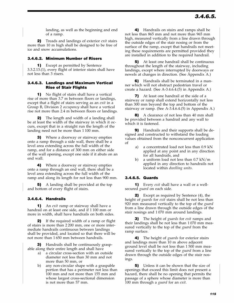
3.4.6.5.
landing, as well as the beginning and endof a ramp.
2) Treads and landings of exterior exit stairsmore than 10 m high shall be designed to be free ofice and snow accumulations.
3.4.6.2. Minimum Number of Risers
1) Except as permitted by Sentence3.3.2.13.(1), every flight of interior stairs shall havenot less than 3 risers.
3.4.6.3. Landings and Maximum VerticalRise of Stair Flights
1) No flight of stairs shall have a verticalrise of more than 3.7 m between floors or landings,except that a flight of stairs serving as an exit in aGroup B, Division 2 occupancy shall have a verticalrise not more than 2.4 m between floors or landings.
2) The length and width of a landing shallbe at least the width of the stairway in which it oc-curs, except that in a straight run the length of thelanding need not be more than 1 100 mm.
3) Where a doorway or stairway emptiesonto a ramp through a side wall, there shall be alevel area extending across the full width of theramp, and for a distance of 300 mm on either sideof the wall opening, except one side if it abuts on anend wall.
4) Where a doorway or stairway emptiesonto a ramp through an end wall, there shall be alevel area extending across the full width of theramp and along its length for not less than 900 mm.
5) A landing shall be provided at the topand bottom of every flight of stairs.
3.4.6.4. Handrails
1) An exit ramp or stairway shall have ahandrail on at least one side, and if 1 100 mm ormore in width, shall have handrails on both sides.
2) If the required width of a ramp or flightof stairs is more than 2 200 mm, one or more inter-mediate handrails continuous between landingsshall be provided, and located so that there will benot more than 1 650 mm between handrails.
3) Handrails shall be continuously grasp-able along their entire length and shall have
a) a circular cross-section with an outsidediameter not less than 30 mm and notmore than 50 mm, or
b) any non-circular shape with a graspableportion that has a perimeter not less than100 mm and not more than 155 mm andwhose largest cross-sectional dimensionis not more than 57 mm.
4) Handrails on stairs and ramps shall benot less than 865 mm and not more than 965 mmhigh, measured vertically from a line drawn throughthe outside edges of the stair nosing or from thesurface of the ramp, except that handrails not meet-ing these requirements are permitted provided theyare installed in addition to the required handrail.
5) At least one handrail shall be continuousthroughout the length of the stairway, includinglandings, except where interrupted by doorways ornewels at changes in direction. (See Appendix A.)
6) Handrails shall be terminated in a man-ner which will not obstruct pedestrian travel orcreate a hazard. (See A-3.4.6.4.(5) in Appendix A.)
7) At least one handrail at the side of astairway or ramp shall extend horizontally not lessthan 300 mm beyond the top and bottom of thestairway or ramp. (See A-3.4.6.4.(5) in Appendix A.)
8) A clearance of not less than 40 mm shallbe provided between a handrail and any wall towhich it is fastened.
9) Handrails and their supports shall be de-signed and constructed to withstand the loadingvalues obtained from the nonconcurrent applicationof
a) a concentrated load not less than 0.9 kNapplied at any point and in any directionfor all handrails, and
b) a uniform load not less than 0.7 kN/mapplied in any direction to handrails notlocated within dwelling units.
3.4.6.5. Guards
1) Every exit shall have a wall or a well-secured guard on each side.
2) Except as required by Sentence (4), theheight of guards for exit stairs shall be not less than920 mm measured vertically to the top of the guardfrom a line drawn through the outside edges of thestair nosings and 1 070 mm around landings.
3) The height of guards for exit ramps andtheir landings shall be not less than 1 070 mm mea-sured vertically to the top of the guard from theramp surface.
4) The height of guards for exterior stairsand landings more than 10 m above adjacentground level shall be not less than 1 500 mm mea-sured vertically to the top of the guard from a linedrawn through the outside edges of the stair nos-ings.
5) Unless it can be shown that the size ofopenings that exceed this limit does not present ahazard, there shall be no opening that permits thepassage of a sphere whose diameter is more than100 mm through a guard for an exit.
115
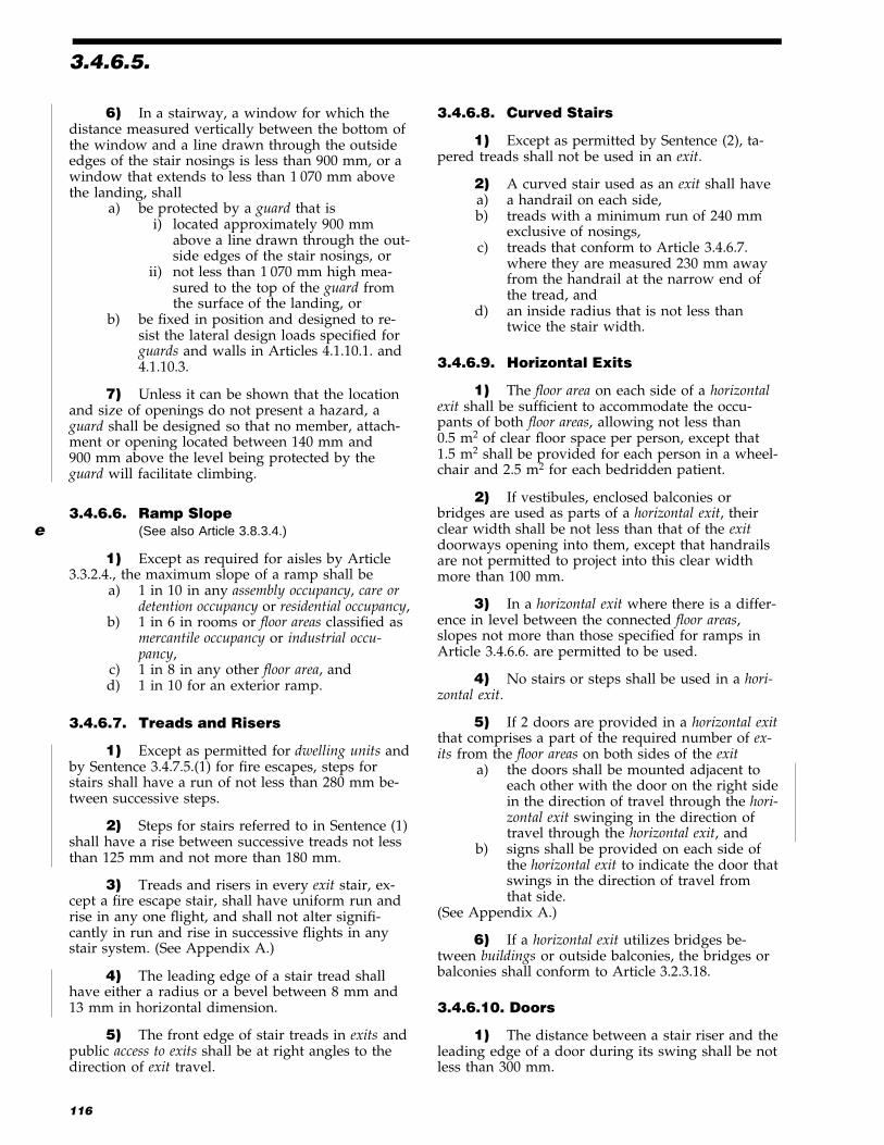
3.4.6.5.
6) In a stairway, a window for which thedistance measured vertically between the bottom ofthe window and a line drawn through the outsideedges of the stair nosings is less than 900 mm, or awindow that extends to less than 1 070 mm abovethe landing, shall
a) be protected by a guard that isi) located approximately 900 mm
above a line drawn through the out-side edges of the stair nosings, or
ii) not less than 1 070 mm high mea-sured to the top of the guard fromthe surface of the landing, or
b) be fixed in position and designed to re-sist the lateral design loads specified forguards and walls in Articles 4.1.10.1. and4.1.10.3.
7) Unless it can be shown that the locationand size of openings do not present a hazard, aguard shall be designed so that no member, attach-ment or opening located between 140 mm and900 mm above the level being protected by theguard will facilitate climbing.
3.4.6.6. Ramp Slope
1) Except as required for aisles by Article3.3.2.4., the maximum slope of a ramp shall be
a) 1 in 10 in any assembly occupancy, care ordetention occupancy or residential occupancy,
b) 1 in 6 in rooms or floor areas classified asmercantile occupancy or industrial occu-pancy,
c) 1 in 8 in any other floor area, andd) 1 in 10 for an exterior ramp.
e (See also Article 3.8.3.4.)
3.4.6.7. Treads and Risers
1) Except as permitted for dwelling units andby Sentence 3.4.7.5.(1) for fire escapes, steps forstairs shall have a run of not less than 280 mm be-tween successive steps.
2) Steps for stairs referred to in Sentence (1)shall have a rise between successive treads not lessthan 125 mm and not more than 180 mm.
3) Treads and risers in every exit stair, ex-cept a fire escape stair, shall have uniform run andrise in any one flight, and shall not alter signifi-cantly in run and rise in successive flights in anystair system. (See Appendix A.)
4) The leading edge of a stair tread shallhave either a radius or a bevel between 8 mm and13 mm in horizontal dimension.
5) The front edge of stair treads in exits andpublic access to exits shall be at right angles to thedirection of exit travel.
3.4.6.8. Curved Stairs
1) Except as permitted by Sentence (2), ta-pered treads shall not be used in an exit.
2) A curved stair used as an exit shall havea) a handrail on each side,b) treads with a minimum run of 240 mm
exclusive of nosings,c) treads that conform to Article 3.4.6.7.
where they are measured 230 mm awayfrom the handrail at the narrow end ofthe tread, and
d) an inside radius that is not less thantwice the stair width.
3.4.6.9. Horizontal Exits
1) The floor area on each side of a horizontalexit shall be sufficient to accommodate the occu-pants of both floor areas, allowing not less than0.5 m2 of clear floor space per person, except that1.5 m2 shall be provided for each person in a wheel-chair and 2.5 m2 for each bedridden patient.
2) If vestibules, enclosed balconies orbridges are used as parts of a horizontal exit, theirclear width shall be not less than that of the exitdoorways opening into them, except that handrailsare not permitted to project into this clear widthmore than 100 mm.
3) In a horizontal exit where there is a differ-ence in level between the connected floor areas,slopes not more than those specified for ramps inArticle 3.4.6.6. are permitted to be used.
4) No stairs or steps shall be used in a hori-zontal exit.
5) If 2 doors are provided in a horizontal exitthat comprises a part of the required number of ex-its from the floor areas on both sides of the exit
a) the doors shall be mounted adjacent toeach other with the door on the right sidein the direction of travel through the hori-zontal exit swinging in the direction oftravel through the horizontal exit, and
b) signs shall be provided on each side ofthe horizontal exit to indicate the door thatswings in the direction of travel fromthat side.
(See Appendix A.)
6) If a horizontal exit utilizes bridges be-tween buildings or outside balconies, the bridges orbalconies shall conform to Article 3.2.3.18.
3.4.6.10. Doors
1) The distance between a stair riser and theleading edge of a door during its swing shall be notless than 300 mm.
116

4.1.6.12.
4.1.6.6. Loads for Dining Areas
1) The minimum specified load in Table4.1.6.3. for dining areas may be reduced to 2.4 kPafor dining areas in buildings to be converted forsuch purposes provided that the floor area does notexceed 100 m2 and use of the dining area for otherassembly purposes, including dancing, is precluded.
4.1.6.7. Floor Loads Due to Intended Use
1) Equipment areas and service rooms, facto-ries, storage areas and warehouses shall be designedfor the loads due to their intended use but not lessthan the specified loads listed in Table 4.1.6.3.
4.1.6.8. More Than One Occupancy
1) Where an area of floor or roof is intendedfor 2 or more occupancies at different times, thevalue to be used from Table 4.1.6.3. shall be thegreatest value for any of the occupancies concerned.
4.1.6.9. Variation with Tributary Area(See Appendix A.)
1) An area used for assembly occupancies de-signed for a live load of less than 4.8 kPa shall haveno reduction for tributary area.
2) Where a structural member supports atributary area of floor, roof or combination thereofgreater than 80 m2 used for assembly occupancies de-signed for a live load of 4.8 kPa or more, or forstorage, manufacturing, retail stores, garages or as afootbridge, the specified live load due to use andoccupancy, excluding snow, is the load provided forin Article 4.1.6.3. multiplied by
0:5 +p20=A
where A is the tributary area in square metres forthis type of use and occupancy, excluding the areasupporting snow.
3) Where a structural member supports atributary area of floor, roof or combination of thesegreater than 20 m2 for any use or occupancy otherthan those indicated in Sentences (1) and (2), thespecified live load due to use and occupancy, exclud-ing snow, is the load provided for in Article 4.1.6.3.multiplied by
0:3 +p9:8=B
where B is the tributary area in square metres forthis type of use and occupancy, excluding the areasupporting snow.
4.1.6.10. Concentrated Loads
1) The specified load due to possible con-centrations of load resulting from the use of an areaof floor or roof shall not be less than that listed inTable 4.1.6.10. applied over an area of 750 mm by750 mm located so as to cause maximum effects, ex-cept that for occupancies not listed in Table 4.1.6.10.the concentrations of load shall be determined in ac-cordance with Article 4.1.6.2.
Table 4.1.6.10.Specified Concentrated Live Loads on an Area of Floor or
RoofForming Part of Article 4.1.6.10.
Area of Floor or Roof
MinimumSpecified
ConcentratedLoad, kN
Roof surfaces 1.3
Floors of classrooms 4.5
Floors of offices, manufacturingbuildings, hospital wards and stages 9.0
Floors and areas used by passengercars 11
Floors and areas used by vehicles notexceeding 3 600 kg gross weight 18
Floors and areas used by vehiclesexceeding 3 600 kg but notexceeding 9 000 kg gross weight 36
Floors and areas used by vehiclesexceeding 9 000 kg gross weight(1) 54
Driveways and sidewalks overareaways and basements(1) 54
Notes to Table 4.1.6.10.:(1) See Appendix A.
4.1.6.11. Bleacher Seats
1) Bleacher seats shall be designed for auniformly distributed load of 1.75 kN for each lin-ear metre or for a concentrated load of 2.2 kNdistributed over a length of 0.75 m, whichever pro-duces the greatest effect on the supporting members.
4.1.6.12. Helicopter Landing Areas
1) Helicopter landing areas on roofs shall beconstructed in conformance with requirementscontained in the “Airport Regulations of the Aero-nautics Act” of Transport Canada.
143
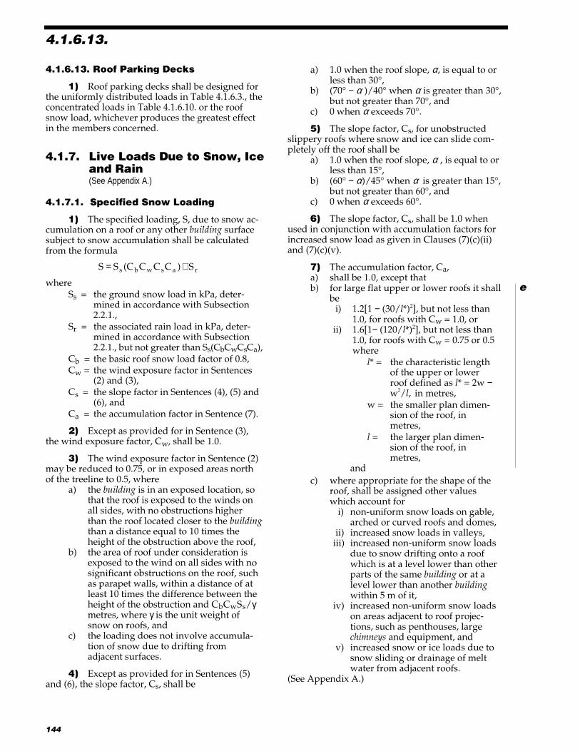
4.1.6.13.
144
4.1.6.13. Roof Parking Decks
1) Roof parking decks shall be designed forthe uniformly distributed loads in Table 4.1.6.3., theconcentrated loads in Table 4.1.6.10. or the roofsnow load, whichever produces the greatest effectin the members concerned.
4.1.7. Live Loads Due to Snow, Iceand Rain
(See Appendix A.)
4.1.7.1. Specified Snow Loading
1) The specified loading, S, due to snow ac-cumulation on a roof or any other building surfacesubject to snow accumulation shall be calculatedfrom the formula
raswbs S)CCC(CSS +=
whereSs = the ground snow load in kPa, deter-
mined in accordance with Subsection2.2.1.,
Sr = the associated rain load in kPa, deter-mined in accordance with Subsection2.2.1., but not greater than Ss(CbCwCsCa),
Cb = the basic roof snow load factor of 0.8,Cw = the wind exposure factor in Sentences
(2) and (3),Cs = the slope factor in Sentences (4), (5) and
(6), andCa = the accumulation factor in Sentence (7).
2) Except as provided for in Sentence (3),the wind exposure factor, Cw, shall be 1.0.
3) The wind exposure factor in Sentence (2)may be reduced to 0.75, or in exposed areas northof the treeline to 0.5, where
a) the building is in an exposed location, sothat the roof is exposed to the winds onall sides, with no obstructions higherthan the roof located closer to the buildingthan a distance equal to 10 times theheight of the obstruction above the roof,
b) the area of roof under consideration isexposed to the wind on all sides with nosignificant obstructions on the roof, suchas parapet walls, within a distance of atleast 10 times the difference between theheight of the obstruction and CbCwSs/γmetres, where γ is the unit weight ofsnow on roofs, and
c) the loading does not involve accumula-tion of snow due to drifting fromadjacent surfaces.
4) Except as provided for in Sentences (5)and (6), the slope factor, Cs, shall be
a) 1.0 when the roof slope, α, is equal to orless than 30°,
b) (70° − α )/40° when α is greater than 30°,but not greater than 70°, and
c) 0 when α exceeds 70°.
5) The slope factor, Cs, for unobstructedslippery roofs where snow and ice can slide com-pletely off the roof shall be
a) 1.0 when the roof slope, α , is equal to orless than 15°,
b) (60° − α)/45° when α is greater than 15°,but not greater than 60°, and
c) 0 when α exceeds 60°.
6) The slope factor, Cs, shall be 1.0 whenused in conjunction with accumulation factors forincreased snow load as given in Clauses (7)(c)(ii)and (7)(c)(v).
7) The accumulation factor, Ca,a) shall be 1.0, except thatb) for large flat upper or lower roofs it shall
bei) 1.2[1 − (30/l*)2], but not less than
1.0, for roofs with Cw = 1.0, orii) 1.6[1− (120/l*)2], but not less than
1.0, for roofs with Cw = 0.75 or 0.5where
l* = the characteristic lengthof the upper or lowerroof defined as l* = 2w −w2/l, in metres,
w = the smaller plan dimen-sion of the roof, inmetres,
l = the larger plan dimen-sion of the roof, inmetres,
andc) where appropriate for the shape of the
roof, shall be assigned other valueswhich account for i) non-uniform snow loads on gable,
arched or curved roofs and domes, ii) increased snow loads in valleys,iii) increased non-uniform snow loads
due to snow drifting onto a roofwhich is at a level lower than otherparts of the same building or at alevel lower than another buildingwithin 5 m of it,
iv) increased non-uniform snow loadson areas adjacent to roof projec-tions, such as penthouses, largechimneys and equipment, and
v) increased snow or ice loads due tosnow sliding or drainage of meltwater from adjacent roofs.
(See Appendix A.)
e

Part 5Environmental Separation(See Appendix A.)
Section 5.1. General5.1.1. Scope
5.1.1.1. Scope
1) The scope of this Part shall be as de-scribed in Section 2.1. (See Appendix A.)
5.1.2. Application
5.1.2.1. Separation of Environments
1) This Part applies toa) the control of condensation in and on,
and the transfer of heat, air and moisturethrough building elements and interfacesbetween building elements that separate
i) interior space from exterior space,ii) interior space from the ground, and
iii) environmentally dissimilar interiorspaces, and
b) site conditions that may affect moistureloading on building elements that sepa-rate interior space from exterior space,and interior space from the ground.
(See Appendix A.)
5.1.3. Definitions
5.1.3.1. Defined Words
1) Words that appear in italics are definedin Part 1.
5.1.4. Environmental SeparationRequirements
5.1.4.1. Resistance to EnvironmentalLoads
1) Building components and assemblies thatseparate dissimilar environments shall
a) be designed to have sufficient capacityand integrity to resist or accommodate allenvironmental loads and effects of thoseloads that may be reasonably expected,having regard to
i) the intended use of the building, and
ii) the environment to which the com-ponents and assemblies are subject,and
b) satisfy the requirements of this Part.
5.1.4.2. Resistance to Deterioration(See Appendix A.)
1) Except as provided in Sentence (2),materials that comprise building components and as-semblies that separate dissimilar environments shallbe:
a) compatible with adjoining materials, andb) resistant to any mechanisms of deteriora-
tion which would be reasonablyexpected, given the nature, function andexposure of the materials.
2) Material compatibility and deteriorationresistance are not required where it can be shownthat incompatibility or uncontrolled deteriorationwill not adversely affect any of
a) the health or safety of building users,b) the intended use of the building, orc) the operation of building services.
5.1.5. Other Requirements
5.1.5.1. Requirements in Other Parts ofthe Code
1) Acoustical, structural and fire safety re-quirements of other Parts of this Code shall apply.
Section 5.2. Loads andProcedures5.2.1. Environmental Loads
5.2.1.1. Exterior Environmental Loads
1) Except as provided in Sentences (2) and(3), climatic loads shall be determined according toSection 2.2.
2) Except as provided in Sentence (3), belowground exterior environmental loads not described
161

5.2.1.1.
in Section 2.2. shall be determined from existing ge-ological and hydrological data or from site tests.
3) Where local design and constructionpractice has shown soil temperature analysis to beunnecessary, soil temperatures need not be deter-mined. (See Appendix A.)
5.2.1.2. Interior Environmental Loads
1) Interior environmental loads shall be de-rived from the intended use of the space. (SeeAppendix A.)
5.2.2. Procedures
5.2.2.1. Calculations
1) Heat, air and moisture transfer calcula-tions shall conform to good practice such asdescribed in the ASHRAE Handbooks.
2) For the purposes of any analysis con-ducted to indicate conformance to the thermalresistance levels required in Article 5.3.1.2., soil tem-peratures shall be determined based on annualaverage soil temperature, seasonal amplitude ofvariation and attenuation of variation with depth.
3) Wind load calculations shall conform toSubsection 4.1.8.
Section 5.3. HeatTransfer(See Appendix A.)
5.3.1. Thermal Resistance ofAssemblies
5.3.1.1. Required Resistance to HeatTransfer(See Appendix A.)
1) Except as provided in Sentence (2), wherea building component or assembly will be subjectedto an intended temperature differential, the compo-nent or assembly shall include materials to resistheat transfer in accordance with the remainder ofthis Subsection.
2) The installation of materials to resist heattransfer in accordance with the remainder of thisSubsection is not required where it can be shownthat uncontrolled heat transfer will not adversely af-fect any of
a) the health or safety of building users,b) the intended use of the building, orc) the operation of building services.
5.3.1.2. Properties to Resist Heat Transfer(See Appendix A.)
1) Materials and components installed toprovide the required resistance to heat transfer shallprovide sufficient resistance, for the interior and ex-terior design temperatures,
a) to minimize surface condensation on thewarm side of the component or assembly,
b) in conjunction with other materials andcomponents in the assembly, to minimizecondensation within the component orassembly, and
c) in conjunction with systems installed forspace conditioning, to meet the interiordesign thermal conditions for the in-tended occupancy.
2) Except as provided in Sentence (3), wherematerials or components are installed to provide therequired resistance to heat transfer and are coveredin the scope of the standards listed below, thematerials and components shall conform to the re-quirements of the respective standards:
a) CAN/CGSB-12.8-M, “Insulating GlassUnits,”
b) CAN/ULC-S701, “Thermal Insula- rtion, Polystyrene, Boards and PipeCovering,”
c) CGSB 51-GP-21M, “Thermal Insulation,Urethane and Isocyanurate, Unfaced,”
d) CAN/CGSB-51.23, “Spray-Applied RigidPolyurethane Cellular Plastic Thermal In-sulation,”
e) CAN/CGSB-51.25-M, “Thermal Insula-tion, Phenolic, Faced,”
f) CAN/CGSB-51.26-M, “Thermal Insula-tion, Urethane and Isocyanurate, Boards,Faced,”
g) CGSB 51-GP-27M, “Thermal Insulation,Polystyrene, Loose Fill,”
h) CAN/CGSB-51.60-M, “Cellulose FibreLoose Fill Thermal Insulation,”
i) CAN/CGSB-82.1-M, “Sliding Doors,”j) CAN/CGSB-82.5-M, “Insulated Steel
Doors,”k) CAN/ULC-S702, “Thermal Insulation, Min- r
eral Fibre, for Buildings,” orl) CAN/CSA-A247-M, “Insulating Fibre-
board.”(See Appendix A.)
3) The requirements for flame-spread ratingscontained in the standards listed in Sentence (2)need be applied only as required in Part 3.
4) Except as provided in Sentence (5), allmetal-framed glazed assemblies separating interiorconditioned space from interior unconditioned spaceor exterior space shall incorporate a thermal breakto minimize condensation.
162

5.4.1.2.
5) Metal framed glazed assemblies need notcomply with Sentence (4) where these assemblies are
a) storm windows or doors, orb) windows or doors which are required to
have a fire resistance rating.(See Appendix A.)
5.3.1.3. Location and Installation ofMaterials Providing ThermalResistance
1) Where a material required by Article5.3.1.1. is intersected by a building assembly,penetrated by a high conductance component or in-terrupted by expansion, control or constructionjoints, and where condensation is likely to occur atthese intersections, penetrations or interruptions,sufficient thermal resistance shall be provided so asto minimize condensation at these locations.
2) Materials providing required thermal re-sistance shall have sufficient inherent resistance toair flow or be positioned in the assembly so as toprevent convective air flow through and around thematerial. (See Appendix A.)
3) Spray-in-place polyurethane insulationshall be installed in accordance with the require-ments of CAN/CGSB-51.39, “Sprayed Application ofRigid Polyurethane Cellular Plastic Thermal Insula-tion for Building Construction.”
Section 5.4. Air Leakage5.4.1. Air Barrier Systems
5.4.1.1. Required Resistance to AirLeakage(See Appendix A.)
1) Except as provided in Sentence (2), wherea building component or assembly separates interiorconditioned space from exterior space, interior spacefrom the ground, or environmentally dissimilar in-terior spaces, the component or assembly shallcontain an air barrier system.
2) An air barrier system is not requiredwhere it can be shown that uncontrolled air leakagewill not adversely affect any of
a) the health or safety of building users,b) the intended use of the building, orc) the operation of building services.
5.4.1.2. Air Barrier System Properties
1) Except as provided in Sentence (2), sheetand panel type materials intended to provide theprincipal resistance to air leakage shall have an airleakage characteristic not greater than
0.02 L/(s • m2) measured at an air pressure differ-ence of 75 Pa. (See Appendix A.)
2) The air leakage limit specified inSentence (1) is permitted to be increased where itcan be shown that the higher rate of leakage willnot adversely affect any of
a) the health or safety of the building users,b) the intended use of the building, orc) the operation of building services.
(See Appendix A.)
3) Except as provided in Sentence (6), wherecomponents of the air barrier system are covered inthe scope of the standards listed below, the compo-nents shall conform to the requirements of therespective standards:
a) CAN/CGSB-63.14-M, “Plastic Skylights,”b) CAN/CGSB-82.1-M, “Sliding Doors,”c) CAN/CGSB-82.5-M, “Insulated Steel
Doors,” ord) CAN/CSA-A440-M, “Windows.”
(See Appendix A.)
4) Skylights not covered in the scope ofCAN/CGSB-63.14-M, “Plastic Skylights,” shall con-form to the performance requirements of thatstandard.
5) Except as provided in Sentence (6), win-dows and sliding doors covered in the scope ofCAN/CGSB-82.1-M, “Sliding Doors,” or CAN/CSA-A440-M, “Windows,” and installed as componentsin an air barrier system shall conform at least to theairtightness requirements in CSA A440.1-M, “UserSelection Guide to CAN/CSA-A440-M90 Windows.”
6) Where a wired glass assembly is installedas a component in an air barrier system in a requiredfire separation, the assembly need not conform toCAN/CSA-A440-M, “Windows” or CSA A440.1-M,“User Selection Guide to CAN/CSA-A440-M90 Win-dows.” (See Appendix A.)
7) The air barrier system shall be continuousa) across construction, control and expan-
sion joints,b) across junctions between different
building assemblies, andc) around penetrations through the building
assembly.
8) An air barrier system installed in anassembly subject to wind load, and other elementsof the separator that will be subject to wind load,shall transfer that load to the structure.
9) Except as provided in Sentence (11), anair barrier system installed in an assembly subject towind load shall be designed and constructed to re-sist 100% of the specified wind load as determinedaccording to Subsection 4.1.8. for cladding. r
10) Except as provided in Sentence (11), de-flections of the air barrier system and other elements
163

5.4.1.2.
of the separator that will be subject to wind loadshall not adversely affect non-structural elements at1.5 times the specified wind load.
11) Where it can be shown by test or analysisthat an air barrier system installed in an assemblywill be subject to less than 100% of the specifiedwind load,
a) the air barrier system is permitted to bedesigned and constructed to resist thelesser load, and
b) deflections of the air barrier system andother elements of the separator that willbe subject to wind load shall not ad-versely affect non-structural elements at1.5 times the lesser load.
Section 5.5. VapourDiffusion5.5.1. Vapour Barriers
5.5.1.1. Required Vapour Barrier
1) Except as provided in Sentence (2), wherea building component or assembly will be subjectedto a temperature differential and a differential inwater vapour pressure, the component or assemblyshall include a vapour barrier.
2) A vapour barrier is not required where itcan be shown that uncontrolled vapour diffusionwill not adversely affect any of
a) the health or safety of building users,b) the intended use of the building, orc) the operation of building services.
5.5.1.2. Vapour Barrier Properties andInstallation(See A-5.3.1.2 in Appendix A.)
1) The vapour barrier shall have sufficientlylow permeance and shall be positioned in thebuilding component or assembly so as to
a) minimize moisture transfer by diffusion,to surfaces within the assembly thatwould be cold enough to cause conden-sation at the design temperature andhumidity conditions, or
b) reduce moisture transfer by diffusion, tosurfaces within the assembly that wouldbe cold enough to cause condensation atthe design temperature and humidityconditions, to a rate that will not allowsufficient accumulation of moisture tocause deterioration or otherwise ad-versely affect any of
i) the health or safety of building users,ii) the intended use of the building, or
iii) the operation of building services.
(See Appendix A.)
2) Where materials installed to provide therequired resistance to vapour diffusion are coveredin the scope of the standards listed below, the mate-rials shall conform to the requirements of therespective standards:
a) CAN/CGSB-51.33-M, “Vapour Barrier,Sheet, Excluding Polyethylene, for Use inBuilding Construction,” or
b) CAN/CGSB-51.34-M, “Vapour Barrier,Polyethylene Sheet for Use in BuildingConstruction.”
(See Appendix A.)
3) Coatings applied to gypsum wallboard toprovide required resistance to vapour diffusionshall be shown to conform with the requirements ofSentence (1) when tested in accordance with CAN/CGSB-1.501-M, “Method for Permeance of CoatedWallboard.”
4) Coatings applied to materials other thangypsum wallboard to provide required resistance tovapour diffusion shall be shown to conform withthe requirements of Sentence (1) when tested in ac-cordance with ASTM E 96, “Water VaporTransmission of Materials,” by the desiccantmethod (dry cup).
Section 5.6.Precipitation5.6.1. Protection from
Precipitation
5.6.1.1. Required Protection fromPrecipitation(See Appendix A.)
1) Except as provided in Sentence (2), wherea building component or assembly is exposed to pre-cipitation, the component or assembly shall
a) minimize ingress of precipitation into thecomponent or assembly, and
b) prevent ingress of precipitation into inte-rior space.
2) Protection from ingress of precipitation isnot required where it can be shown that suchingress will not adversely affect any of
a) the health or safety of building users,b) the intended use of the building, orc) the operation of building services.
5.6.1.2. Protective Material andComponent Properties
1) Where materials or components appliedto sloped or horizontal assemblies are installed to
164

5.6.1.2.
165
r
r
r
r
r
provide required protection from precipitation andare covered in the scope of the standards listed be-low, the materials or components shall conform tothe requirements of the respective standards:
a) ASTM D 2178, “Asphalt Glass Felt Usedin Roofing and Waterproofing,”
b) CAN/CGSB-37.4-M, “Fibrated, CutbackAsphalt, Lap Cement for Asphalt Roof-ing,”
c) CAN/CGSB-37.5-M, “Cutback AsphaltPlastic Cement,”
d) CAN/CGSB-37.8-M, “Asphalt, Cutback,Filled, for Roof Coating,”
e) CGSB 37-GP-9Ma, “Primer, Asphalt,Unfilled, for Asphalt Roofing, Damp-proofing and Waterproofing,”
f) CGSB 37-GP-21M, “Tar, Cutback, Fi-brated, for Roof Coating,”
g) CAN/CGSB-37.50-M, “Hot Applied Rub-berized Asphalt for Roofing andWaterproofing,”
h) CGSB 37-GP-52M, “Roofing and Water-proofing Membrane, Sheet Applied,Elastomeric,”
i) CAN/CGSB-37.54, “Polyvinyl ChlorideRoofing and Waterproofing Membrane,”
j) CGSB 37-GP-56M, “Membrane, Modified,Bituminous, Prefabricated, and Rein-forced for Roofing,”
k) CGSB 37-GP-64M, “Mat Reinforcing,Fibrous Glass, for Membrane Water-proofing Systems and Built-Up Roofing,”
l) CGSB 41-GP-6M, “Sheets, ThermosettingPolyester Plastics, Glass Fiber Rein-forced,”
m) CAN/CGSB-51.32-M, “Sheathing,Membrane, Breather Type,”
n) CAN/CGSB-63.14-M, “Plastic Skylights,”o) CSA A123.1-M, “Asphalt Shingles Sur-
faced with Mineral Granules,”p) CSA A123.2-M, “Asphalt Coated Roofing
Sheets,”q) CSA A123.3-M, “Asphalt or Tar Satu-
rated Roofing Felt,”r) CSA A123.4-M, “Bitumen for Use in
Construction of Built-Up Roof Coveringsand Dampproofing and WaterproofingSystems,”
s) CAN/CSA-A123.5-M, “Asphalt ShinglesMade from Glass Felt and Surfaced withMineral Granules,”
t) CSA A123.17, “Asphalt-Saturated FeltedGlass-Fibre Mat for Use in Constructionof Built-Up Roofs,”
u) CAN/CSA-A220.0-M, “Performance ofConcrete Roof Tiles,”
v) CSA O118.1, “Western Cedars, Shakesand Shingles,” not less than No. 2grade, or
w) CSA-O118.2-M, “Eastern White Cedar…….Shingles,” not less than B grade.
(See Appendix A.)
2) Skylights that are not covered in thescope of CAN/CGSB-63.14-M, “Plastic Skylights,”shall conform to the performance requirements ofthat standard.
3) Except as provided in Sentence (5), wherematerials or components applied to vertical assem-blies are installed to provide required protectionfrom precipitation and are covered in the scope ofthe standards listed below, the materials or compo-nents shall conform to the requirements of therespective standards:
a) ASTM C 212, “Structural Clay FacingTile,”
b) CAN/CGSB-11.3-M, “Hardboard,” types1, 2 or 5 when not factory finished,
c) CAN/CGSB-11.5-M, “Hardboard, Pre-coated, Factory Finished, for ExteriorCladding,”
d) CAN/CGSB-34.4-M, “Siding, Asbestos-Cement, Shingles and Clapboards,”
e) CAN/CGSB-34.5-M, “Sheets, Asbestos-Cement, Corrugated,”
f) CAN/CGSB-34.14-M, “Sheets, Asbestos-Cement, Decorative,”
g) CAN/CGSB-34.16-M, “Sheets, Asbestos-Cement, Flat, Fully Compressed,”
h) CAN/CGSB-34.17-M, “Sheets, Asbestos-Cement, Flat, Semicompressed,”
i) CAN/CGSB-34.21-M, “Panels, Sandwich,Asbestos-Cement with Insulating Cores,”
j) CAN/CGSB-41.24, “Rigid Vinyl Siding,Soffits and Fascia,”
k) CAN/CGSB-51.32-M, “Sheathing,Membrane, Breather Type,”
l) CAN/CGSB-82.1-M, “Sliding Doors,” rm) CAN/CGSB-82.5-M, “Insulated Steel r
Doors,”n) CAN/CGSB-93.1-M, “Sheet, Aluminum r
Alloy, Prefinished, Residential,”o) CAN/CGSB-93.2-M, “Prefinished Alu- r
minum Siding, Soffits and Fascia, forResidential Use,”
p) CAN/CGSB-93.3-M, “Prefinished Galva- rnized and Aluminum-Zinc Alloy SteelSheet for Residential Use,”
q) CAN/CGSB-93.4, “Galvanized and rAluminum-Zinc Alloy Coated Steel Siding,Soffits and Fascia, Prefinished, Residential,”
r) CSA A371, “Masonry Construction for rBuildings,” Section 4,
s) CAN/CSA-A440-M, “Windows,” rt) CSA O115-M, “Hardwood and Decora- r
tive Plywood,”u) CSA O118.1, “Western Cedars, Shakes and
Shingles,” with shakes not less than No. 1grade and shingles not less than No. 2grade, except that No. 3 grade may be usedfor undercoursing,

5.6.1.2.
r v) CSA O118.2-M, “Eastern White CedarShingles,” not less than B (clear) grade,except that C grade may be used for un-dercoursing,
r w) CSA O121-M, “Douglas Fir Plywood,”r x) CSA O151-M, “Canadian Softwood Ply-
wood,”r y) CSA O153-M, “Poplar Plywood,”r z) CAN/CSA-O325.0, “Construction Sheath-
ing,” orr aa) CSA O437.0, “OSB and Waferboard.”
(See Appendix A.)
4) Except as provided in Sentence (5), win-dows and sliding doors exposed to the exterior andcovered in the scope of CAN/CSA-A440-M, “Win-dows,” or CAN/CGSB-82.1-M, “Sliding Doors,” shallconform at least to the water tightness requirementsin CSA A440.1-M, “User Selection Guide to CAN/CSA-A440-M90 Windows.”
5) Where a wired glass assembly in a re-quired fire separation is exposed to the exterior, theassembly need not conform to CAN/CSA-A440-M,“Windows,” or CSA A440.1-M, “User SelectionGuide to CAN/CSA-A440-M90 Windows.” (SeeAppendix A.)
5.6.1.3. Installation of ProtectiveMaterials
1) Where a material applied to a sloped orhorizontal assembly is installed to provide requiredprotection from precipitation and its installation iscovered in the scope of one of the standards listedbelow, installation shall conform to the require-ments of the respective standard:
a) CAN/CGSB-37.51-M, “Application ofHot-Applied Rubberized Asphalt forRoofing and Waterproofing,”
b) CGSB 37-GP-55M, “Application of SheetApplied Flexible Polyvinyl ChlorideRoofing Membrane,”
c) CAN3-A123.51-M, “Asphalt Shingle Ap-plication on Roof Slopes 1:3 and Steeper,”or
d) CAN3-A123.52-M, “Asphalt Shingle Ap-plication on Roof Slopes 1:6 to Less Than1:3.”
2) Protective materials applied to sloped orhorizontal assemblies shall be installed to resistwind-uplift loads determined according to Sub-section 4.1.8.
3) Where masonry applied to vertical as-semblies is installed to provide required protectionfrom precipitation, installation shall conform to therequirements of CSA A371, “Masonry Constructionfor Buildings.”
4) Where protective materials applied to as-semblies are installed to provide required protectionfrom precipitation, the materials shall be installed to
shed precipitation or otherwise minimize its entryinto the assembly and prevent its penetrationthrough the assembly.
5.6.2. Sealing, Drainage,Accumulation and Disposal
5.6.2.1. Sealing and Drainage(See Appendix A.)
1) Except as provided in Sentence (2), mate-rials, components, assemblies, joints in materials,junctions between components and junctions be-tween assemblies exposed to precipitation shall be
a) sealed to prevent ingress of precipitation,or
b) drained to direct precipitation to the exte-rior.
2) Sealing or drainage are not requiredwhere it can be shown that the omission of sealingand drainage will not adversely affect any of
a) the health or safety of building users,b) the intended use of the building, orc) the operation of building services.
5.6.2.2. Accumulation and Disposal
1) Where water, snow or ice can accumulateon a building, provision shall be made to minimizethe likelihood of hazardous conditions arising fromsuch accumulation.
2) Where precipitation can accumulate onsloped or horizontal assemblies, provision shall bemade for drainage conforming with the relevantprovincial, territorial or municipal regulations or, inthe absence of such regulations, with Article 4.10.4.of the National Plumbing Code of Canada 1995.
3) Where downspouts are provided and arenot connected to a sewer, provisions shall be madeto
a) divert the water from the building, andb) prevent soil erosion.
4) Junctions between vertical assemblies,and sloped or horizontal assemblies, shall be de-signed and constructed to minimize the flow ofwater from the sloped or horizontal assembly ontothe vertical assembly.
166
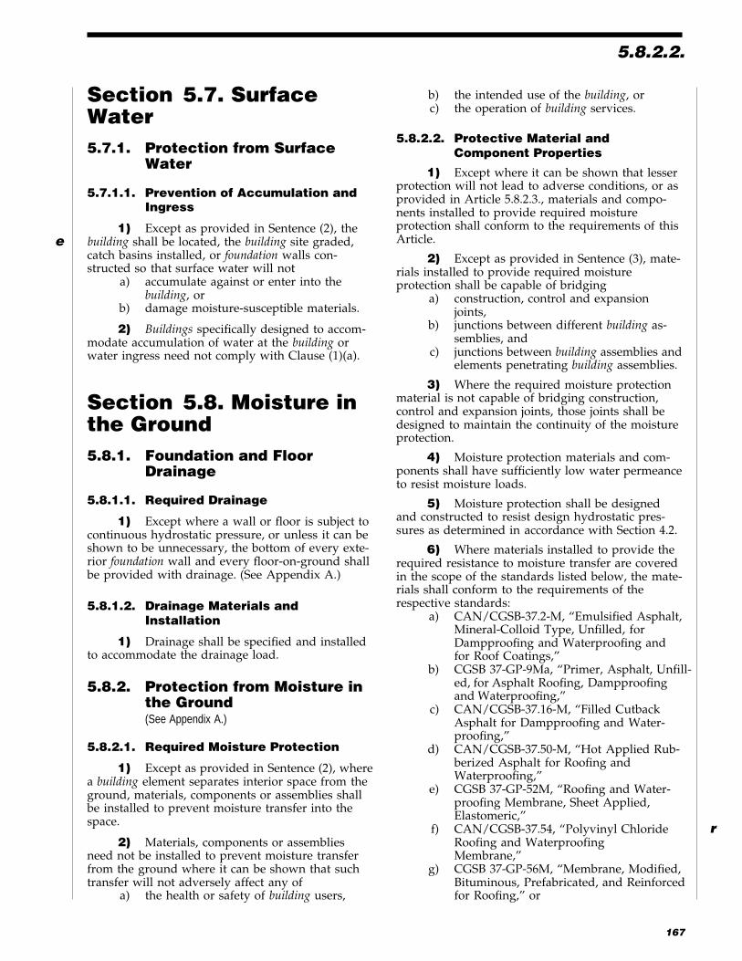
5.8.2.2.
Section 5.7. SurfaceWater5.7.1. Protection from Surface
Water
5.7.1.1. Prevention of Accumulation andIngress
1) Except as provided in Sentence (2), thee building shall be located, the building site graded,
catch basins installed, or foundation walls con-structed so that surface water will not
a) accumulate against or enter into thebuilding, or
b) damage moisture-susceptible materials.
2) Buildings specifically designed to accom-modate accumulation of water at the building orwater ingress need not comply with Clause (1)(a).
Section 5.8. Moisture inthe Ground5.8.1. Foundation and Floor
Drainage
5.8.1.1. Required Drainage
1) Except where a wall or floor is subject tocontinuous hydrostatic pressure, or unless it can beshown to be unnecessary, the bottom of every exte-rior foundation wall and every floor-on-ground shallbe provided with drainage. (See Appendix A.)
5.8.1.2. Drainage Materials andInstallation
1) Drainage shall be specified and installedto accommodate the drainage load.
5.8.2. Protection from Moisture inthe Ground(See Appendix A.)
5.8.2.1. Required Moisture Protection
1) Except as provided in Sentence (2), wherea building element separates interior space from theground, materials, components or assemblies shallbe installed to prevent moisture transfer into thespace.
2) Materials, components or assembliesneed not be installed to prevent moisture transferfrom the ground where it can be shown that suchtransfer will not adversely affect any of
a) the health or safety of building users,
b) the intended use of the building, orc) the operation of building services.
5.8.2.2. Protective Material andComponent Properties
1) Except where it can be shown that lesserprotection will not lead to adverse conditions, or asprovided in Article 5.8.2.3., materials and compo-nents installed to provide required moistureprotection shall conform to the requirements of thisArticle.
2) Except as provided in Sentence (3), mate-rials installed to provide required moistureprotection shall be capable of bridging
a) construction, control and expansionjoints,
b) junctions between different building as-semblies, and
c) junctions between building assemblies andelements penetrating building assemblies.
3) Where the required moisture protectionmaterial is not capable of bridging construction,control and expansion joints, those joints shall bedesigned to maintain the continuity of the moistureprotection.
4) Moisture protection materials and com-ponents shall have sufficiently low water permeanceto resist moisture loads.
5) Moisture protection shall be designedand constructed to resist design hydrostatic pres-sures as determined in accordance with Section 4.2.
6) Where materials installed to provide therequired resistance to moisture transfer are coveredin the scope of the standards listed below, the mate-rials shall conform to the requirements of therespective standards:
a) CAN/CGSB-37.2-M, “Emulsified Asphalt,Mineral-Colloid Type, Unfilled, forDampproofing and Waterproofing andfor Roof Coatings,”
b) CGSB 37-GP-9Ma, “Primer, Asphalt, Unfill-ed, for Asphalt Roofing, Dampproofingand Waterproofing,”
c) CAN/CGSB-37.16-M, “Filled CutbackAsphalt for Dampproofing and Water-proofing,”
d) CAN/CGSB-37.50-M, “Hot Applied Rub-berized Asphalt for Roofing andWaterproofing,”
e) CGSB 37-GP-52M, “Roofing and Water-proofing Membrane, Sheet Applied,Elastomeric,”
f) CAN/CGSB-37.54, “Polyvinyl Chloride rRoofing and WaterproofingMembrane,”
g) CGSB 37-GP-56M, “Membrane, Modified,Bituminous, Prefabricated, and Reinforcedfor Roofing,” or
167

5.8.2.2.
h) CSA A123.4-M, “Bitumen for Use inConstruction of Built-Up Roof Coveringsand Dampproofing and WaterproofingSystems.”
(See Appendix A.)
7) Except as provided in Sentence (8), mate-rials covered in the scope of the standards listedbelow shall not be installed to provide the requiredresistance to moisture transfer:
a) CGSB 37-GP-6Ma, “Asphalt, Cutback,Unfilled, for Dampproofing,” or
b) CGSB 37-GP-18Ma, “Tar, Cutback, Un-filled, for Dampproofing.”
8) Where the substrate is cast-in-place con-crete, and a drainage layer is installed between thebuilding assembly and the soil, and the assemblywill not be subject to hydrostatic pressure,
a) materials and components installed toprovide the required resistance to mois-ture transfer need not conform withSentences 5.8.2.2.(1) to (5), and
b) materials covered in the scope ofi) CGSB 37-GP-6Ma, “Asphalt, Cut-
back, Unfilled, for Dampproofing,”or
ii) CGSB 37-GP-18Ma, “Tar, Cutback,Unfilled, for Dampproofing,”
are permitted to be installed to providethe required resistance to moisture trans-fer where those materials conform to therequirements of the standards.
(See Appendix A.)
5.8.2.3. Installation of Moisture Protection
1) Except as provided in Sentence (2), wherematerials are installed to provide the required resis-tance to moisture transfer and their installation iscovered in the scope of the standards listed below,installation shall conform to the waterproofing re-quirements of the respective standards:
a) CAN/CGSB-37.3-M, “Application ofEmulsified Asphalts for Dampproofing orWaterproofing,”
b) CGSB 37-GP-36M, “Application of FilledCutback Asphalts for Dampproofing andWaterproofing,”
c) CGSB 37-GP-37M, “Application of HotAsphalt for Dampproofing or Water-proofing,” or
d) CAN/CGSB-37.51-M, “Application ofHot-Applied Rubberized Asphalt forRoofing and Waterproofing.”
2) Where the substrate is cast-in-place con-crete, and a drainage layer is installed between thebuilding assembly and the soil, and the assemblywill not be subject to hydrostatic pressure
a) materials and components installed toprovide the required resistance to mois-ture transfer and whose installation is
covered in the scope of the standardslisted in Sentence (1), are permitted to beinstalled in conformance with the damp-proofing requirements of the standardslisted in Sentence (1), or
b) materials installed to provide the re-quired resistance to moisture transfer andwhose installation is covered in the scopeof the standards listed below, shall beinstalled in conformance with the re-quirements of the respective standards:
i) CGSB 37-GP-12Ma, “Application ofUnfilled Cutback Asphalt forDampproofing,” or
ii) CAN/CGSB-37.22-M, “Applicationof Unfilled Cutback Tar FoundationCoating for Dampproofing.”
(See A-5.8.2.2.(8) in Appendix A.)
168

Part 6Heating, Ventilating and Air-Conditioning
Section 6.1. General6.1.1. Application
6.1.1.1. Scope
1) The scope of this Part shall be as de-scribed in Section 2.1.
6.1.1.2. Application
1) This Part applies to systems and equip-ment for heating, ventilating and air-conditioningservices.
6.1.2. Definitions
6.1.2.1. Defined Terms
1) Words that appear in italics are definedin Part 1.
6.1.3. Plans and Specifications
6.1.3.1. Required Plans and Specifications
1) Plans, specifications and other informa-tion for heating, ventilating and air-conditioningsystems shall conform to Subsection 2.3.5.
Section 6.2. Design andInstallation6.2.1. General
6.2.1.1. Good Engineering Practice
1) Heating, ventilating and air-conditioningsystems, including mechanical refrigeration equip-ment, shall be designed, constructed and installedto conform to good engineering practice such as de-scribed in
a) the ASHRAE Handbooks and Standards,b) the HRAI Digest,c) the Hydronics Institute Manuals,d) the NFPA standards,e) the SMACNA Manuals,f) the Industrial Ventilation Manual pub-
lished by the American Conference ofGovernmental Industrial Hygienists, and
g) CAN/CSA-Z317.2-M, “Special Requirementsfor Heating,Ventilation, and Air Conditioning(HVAC) Systems in Health Care Facilities.”
6.2.1.2. Fire Safety Requirements
1) The fire safety characteristics of heating,ventilating and air-conditioning systems shall com-ply with Subsection 3.6.5.
2) Characteristics referred to in Sentence (1)include but are not limited to
a) use of combustible materials in duct sys-tems,
b) flame-spread ratings and smoke-developedratings of duct and pipe materials andcoverings,
c) installation of equipment relative toproperty lines, and
d) requirements for fire dampers and fire-stopflaps.
6.2.1.3. Capacity of Heating Appliances inDwelling Units
1) The required capacity of a space heatingappliance located in a dwelling unit and serving onlythat dwelling unit, shall be determined in accordancewith CAN/CSA-F280-M, “Determining the RequiredCapacity of Residential Space Heating and CoolingAppliances,” except that the outside winter designtemperatures shall conform to Subsection 2.2.1.
6.2.1.4. Structural Movement
1) Mechanical systems and equipment shallbe designed and installed to accommodate themaximum relative structural movement providedfor in the construction of the building. (See Article4.1.1.5., Subsection 4.1.9. and Article 4.1.10.5. for in- eformation on the types of structural movements thatmay be encountered.) (See Appendix A.) r
6.2.1.5. Installation Standards
1) Except as provided in Articles 6.2.1.6.and 6.2.1.7., the installation of heating and air-conditioning equipment, including mechanicalrefrigeration equipment, and including provisionsfor mounting, clearances and air supply, shall
169

6.2.1.5.
conform to appropriate provincial or territorial re-quirements or, in the absence of such requirements,to the requirements of
a) CAN/CGA-B149.1-M, “Natural Gas Installa-tion Code,”
b) CAN/CGA-B149.2-M, “Propane InstallationCode,”
c) CSA B51, “Boiler, Pressure Vessel, andPressure Piping Code,”
d) CSA B52, “Mechanical RefrigerationCode,”
e) CAN/CSA-B139-M, “Installation Codefor Oil Burning Equipment,”
f) CAN/CSA-B365-M, “Installation Code forSolid-Fuel-Burning Appliances andEquipment,” and
g) CSA C22.1, “Canadian Electrical Code,Part I.”
6.2.1.6. Fireplaces
1) Fireplaces shall conform to the require-ments of Section 9.22.
6.2.1.7. Heat Recovery Ventilators
1) Heat recovery ventilators with rated ca-pacities of not less than 25 L/s and not more than200 L/s shall be installed in accordance with Sub-section 9.32.3.
6.2.1.8. Outside Design Conditions
1) The outside conditions to be used in de-signing heating, ventilating and air-conditioningsystems shall be determined in conformance withSubsection 2.2.1.
6.2.1.9. Installation – General
1) Equipment requiring periodic mainte-nance and forming part of a heating, ventilating orair-conditioning system shall be installed with pro-vision for access for inspection, maintenance, repairand cleaning. (See Appendix A.)
2) Mechanical equipment shall be guardedto prevent injury to the public or maintenance staff.
3) Equipment forming part of a heating orair-conditioning system shall be protected fromfreezing if
a) it may be adversely affected by freezingtemperatures; and
b) it is located in an unheated area.
6.2.1.10. Expansion, Contraction andSystem Pressure
1) Heating and cooling systems shall be de-signed to allow for expansion and contraction of theheat transfer fluid and to maintain the system pres-
sure within the rated working pressure limits of allcomponents of the system.
6.2.1.11. Asbestos
1) Asbestos shall not be used in air distribu-tion systems or equipment in a form or in a locationwhere asbestos fibres could enter the air supply orreturn systems.
6.2.1.12. Access Openings
1) Any covering of an access openingthrough which a person could enter shall be open-able from the inside without the use of keys wherethere is a possibility of the opening being acciden-tally closed while the system or equipment is beingserviced.
6.2.2. Ventilation
6.2.2.1. Required Ventilation
1) Except as provided in Sentence (3), allrooms and spaces in buildings shall be ventilated inaccordance with this Part.
2) Except in storage garages covered byArticle 6.2.2.3., the rates at which outdoor air is sup-plied to rooms and spaces in buildings by ventilationsystems shall be not less than the rates required byASHRAE Standard 62, “Ventilation for AcceptableIndoor Air Quality.”
3) Self-contained mechanical ventilation sys-tems serving only one dwelling unit which conformto the requirements of Subsection 9.32.3. shall beconsidered to satisfy the requirements of this Article.
6.2.2.2. Natural Ventilation
1) The ventilation required by Article6.2.2.1. shall be provided by mechanical ventilationexcept that it can be provided by natural ventilationor a combination of natural and mechanical ventila-tion in
a) buildings of other than residential occu-pancy having an occupant load of not morethan one person per 40 m2 during normaluse,
b) buildings of industrial occupancy where thenature of the process contained thereinpermits or requires the use of large open-ings in the building envelope even duringthe winter, and
c) seasonal buildings not intended to be oc-cupied during the winter.
6.2.2.3. Ventilation of Storage Garages
1) Except as provided in Sentences (4) and(6), an enclosed storage garage shall have a mechani-cal ventilation system designed to
170

6.2.4.3.
6.2.3.13. Supply, Return, Intake andExhaust Air Openings
1) Supply, return and exhaust air openingsin rooms or spaces in buildings when located lessthan 2 m above the floor shall be protected bygrilles having openings of a size that will not allowthe passage of a 15 mm diam sphere.
2) Outdoor air intakes and exhaust outletsat the building exterior shall be designed or locatedso that air entering the building system will not con-tain more contaminants than the normal exterior airof the locality in which the building is situated.
3) Exterior openings for outdoor air intakesand exhaust outlets shall be shielded from the entryof snow and rain and shall be fitted with corrosion-resistant screens of mesh having openings not largerthan 15 mm, except where experience has shownthat climatic conditions require larger openings toavoid icing over of the screen openings.
4) Screens required in Sentence (3) shall beaccessible for maintenance.
6.2.3.14. Filters and Odour RemovalEquipment
1) Air filters for air duct systems shall con-form to the requirements for Class 2 air filter units
r as described in ULC-S111, “Fire Tests for Air FilterUnits.”
2) When electrostatic-type filters are used,they shall be installed so as to ensure that the elec-tric circuit is automatically de-energized when filteraccess doors are opened or, in dwelling units, whenthe furnace circulating fan is not operating.
3) When odour removal equipment of theadsorption type is used it shall be
a) installed to provide access so that ad-sorption material can be reactivated orrenewed, and
b) protected from dust accumulation by airfilters installed on the inlet side.
4) Facilities for flushing and drainage shallbe provided where filters are designed to bewashed in place.
6.2.3.15. Air Washers and EvaporativeCooling Sections or Towers
1) The filter and water evaporation mediumof every air washer and evaporative cooling sectionenclosed within a building shall be made of noncom-bustible material.
2) Sumps for air washer and evaporativecooling sections shall be constructed and installedso that they can be flushed and drained.
3) Evaporative cooling sections or towers ofcombustible material located on or outside buildings
shall have a clearance from sources of ignition suchas chimneys or incinerators of not less than
a) 12 m when the tower exteriorconstruction is noncombustible, and
b) 30 m when the tower exteriorconstruction is combustible.
4) Evaporative cooling sections or towersthe main structure of which exceeds a volume of55 m3 shall comply with the requirements of NFPA214, “Water-Cooling Towers.”
6.2.3.16. Fans and Associated AirHandling Equipment
1) Fans for heating, ventilating and air-conditioning systems shall be located and installedso that their operation
a) does not adversely affect the draft re-quired for proper operation of fuel-firedappliances, and
b) does not allow the air in the duct systemto be contaminated by air or gases fromthe boiler-room or furnace-room.
2) Fans and associated air handling equip-ment, such as air washers, filters and heating andcooling units, when installed on the roof orelsewhere outside the building, shall be of a type de-signed for outdoor use.
6.2.4. Air Ducts for Low CapacityHeating Systems
6.2.4.1. Application
1) The design, construction and installationof air duct distribution systems serving heating sys-tems in which the rated heat input does not exceed120 kW shall conform to this Subsection and Sub-section 6.2.3.
6.2.4.2. Duct Design
1) The design of ducts and fittings shallconform to SMACNA, “HVAC Duct ConstructionStandards – Metal and Flexible.”
6.2.4.3. Construction and Installation ofDucts and Plenums
1) Rectangular panels in plenums and ductsmore than 300 mm wide shall be shaped to providesufficient stiffness.
2) Where the installation of heating supplyducts in walls and floors creates a space between theduct and construction material, the space shall befire stopped with noncombustible material at eachend.
3) Ducts shall be securely supported bymetal hangers, straps, lugs or brackets, except that,
173

6.2.4.3.
where zero clearance is permitted, wooden bracketsmay be used.
4) All round duct joints shall be tight-fittingand lapped not less than 25 mm.
5) Rectangular duct connections shall bemade with S and drive cleats or equivalent mechan-ical connections.
6) Trunk supply ducts shall not be nailed di-rectly to wood members.
7) Branch ducts shall be supported at suit-able spacings to maintain alignment and preventsagging.
8) Combustible ducts in concrete slabs-on-ground that are connected to a furnace supplyplenum shall be located not less than
a) 600 mm from that plenum, andb) 600 mm from its connection to a riser or
register.
9) Ducts in or beneath concrete slabs-on-ground shall be watertight and corrosion-, decay-,and mildew-resistant.
6.2.4.4. Warm-Air Supply Outlets
1) In a dwelling unit, a warm-air supply out-let shall be provided in each finished room which islocated adjacent to unheated space.
2) Except as provided in Sentence (3), whena room described in Sentence (1) is located adjacentto exterior walls, a warm air supply outlet shall belocated so as to bathe at least one exterior wall orwindow with warm air, except in bathrooms, utilityrooms or kitchens, where this may not be practical.
3) Where the heating system is also de-signed to provide ventilation air, ceiling outlets oroutlets located high on interior walls may be in-stalled provided the outlets are
a) designed for this purpose, andb) installed with diffusers.
4) At least one warm-air supply outlet shallbe provided for each 40 m2 of floor area in unfin-ished basements serving dwelling units.
5) The warm air supply outlet required inSentence (4) shall be located so as to provide ade-quate distribution of warm air throughout thebasement.
6) Except for pipeless furnaces and floor fur-naces, the capacity of warm-air supply outletsserving dwelling units
a) shall be not less than the design heat lossfrom the area served, and
b) shall not exceed 3 kW per outlet.
7) In basements and heated crawl spaces, thecalculated heat gain from the supply ducts andplenum surfaces may be considered in calculatingthe design heat loss.
8) Warm-air supply outlets located in fin-ished areas
a) shall be provided with diffusers and ad-justable openings, and
b) shall not be located on a furnace plenum.
9) The temperature of supply air at warm-air supply outlets shall not exceed 70�C.
6.2.4.5. Concrete Slabs-on-Ground
1) Warm-air supply systems for buildings ofresidential occupancy built on concrete slabs-on-ground
a) shall be installed in the slab, andb) shall be of the perimeter loop type or ra-
dial perimeter type.
6.2.4.6. Adjustable Dampers and BalanceStops
1) All branch supply ducts which are not fit-ted with diffusers with adjustable balance stopsshall be
a) supplied with adjustable dampers, andb) fitted with devices to indicate the posi-
tions of the dampers.
6.2.4.7. Return-Air System
1) A public corridor or public stairway shallnot be used as a return-air plenum.
2) Except for a return-air plenum locatedwithin a dwelling unit, where a ceiling assembly isused as a plenum, the requirements of Subsection6.2.3. shall apply.
6.2.5. Heating Appliances, General
6.2.5.1. Location of Appliances
1) Except for appliances installed in dwellingunits, fuel-fired heating appliances shall be located,enclosed or separated from the remainder of thebuilding in conformance with Section 3.6. (See alsoSubsection 9.10.10.)
6.2.5.2. Appliances Installed outside theBuilding
1) Fuel-fired appliances installed on the roofof a building or otherwise outside the building shallbe designed for outdoor use.
6.2.6. Incinerators
6.2.6.1. Applicable Standard
1) The design, construction, installation andalteration of every indoor incinerator shall conformto NFPA 82, “Incinerators, Waste and Linen Han-dling Systems and Equipment.”
174
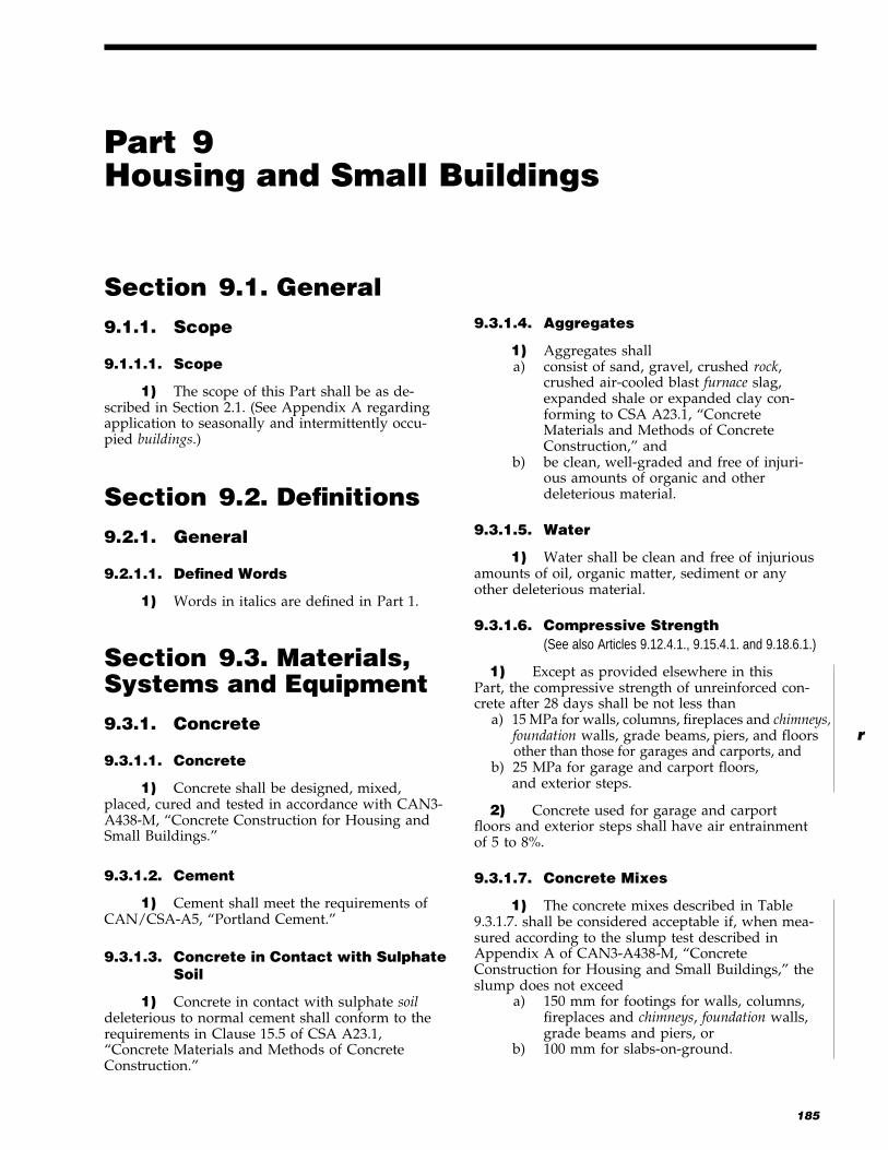
Part 9Housing and Small Buildings
Section 9.1. General9.1.1. Scope
9.1.1.1. Scope
1) The scope of this Part shall be as de-scribed in Section 2.1. (See Appendix A regardingapplication to seasonally and intermittently occu-pied buildings.)
Section 9.2. Definitions9.2.1. General
9.2.1.1. Defined Words
1) Words in italics are defined in Part 1.
Section 9.3. Materials,Systems and Equipment9.3.1. Concrete
9.3.1.1. Concrete
1) Concrete shall be designed, mixed,placed, cured and tested in accordance with CAN3-A438-M, “Concrete Construction for Housing andSmall Buildings.”
9.3.1.2. Cement
1) Cement shall meet the requirements ofCAN/CSA-A5, “Portland Cement.”
9.3.1.3. Concrete in Contact with SulphateSoil
1) Concrete in contact with sulphate soildeleterious to normal cement shall conform to therequirements in Clause 15.5 of CSA A23.1,“Concrete Materials and Methods of ConcreteConstruction.”
9.3.1.4. Aggregates
1) Aggregates shalla) consist of sand, gravel, crushed rock,
crushed air-cooled blast furnace slag,expanded shale or expanded clay con-forming to CSA A23.1, “ConcreteMaterials and Methods of ConcreteConstruction,” and
b) be clean, well-graded and free of injuri-ous amounts of organic and otherdeleterious material.
9.3.1.5. Water
1) Water shall be clean and free of injuriousamounts of oil, organic matter, sediment or anyother deleterious material.
9.3.1.6. Compressive Strength(See also Articles 9.12.4.1., 9.15.4.1. and 9.18.6.1.)
1) Except as provided elsewhere in thisPart, the compressive strength of unreinforced con-crete after 28 days shall be not less than
a) 15 MPa for walls, columns, fireplaces and chimneys,foundation walls, grade beams r, piers, and floorsother than those for garages and carports, and
b) 25 MPa for garage and carport floors,and exterior steps.
2) Concrete used for garage and carportfloors and exterior steps shall have air entrainmentof 5 to 8%.
9.3.1.7. Concrete Mixes
1) The concrete mixes described in Table9.3.1.7. shall be considered acceptable if, when mea-sured according to the slump test described inAppendix A of CAN3-A438-M, “ConcreteConstruction for Housing and Small Buildings,” theslump does not exceed
a) 150 mm for footings for walls, columns,fireplaces and chimneys, foundation walls,grade beams and piers, or
b) 100 mm for slabs-on-ground.
185
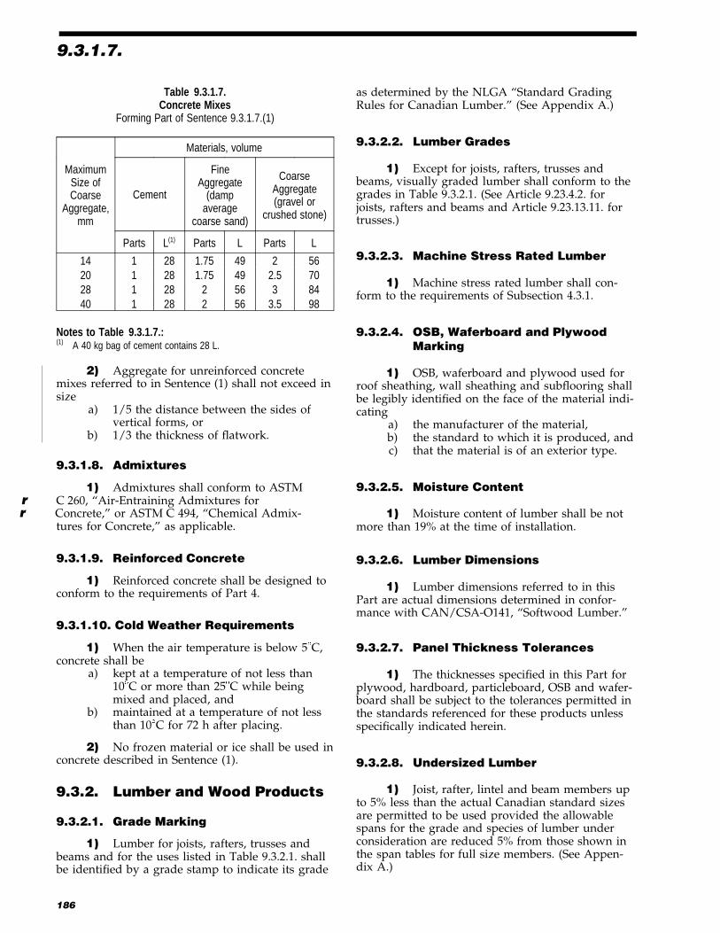
9.3.1.7.
Table 9.3.1.7.Concrete Mixes
Forming Part of Sentence 9.3.1.7.(1)
Materials, volume
Cement
FineAggregate
(dampaverage
coarse sand)
CoarseAggregate(gravel or
crushed stone)
MaximumSize ofCoarse
Aggregate,mm
Parts L(1) Parts L Parts L
14 1 28 1.75 49 2 5620 1 28 1.75 49 2.5 7028 1 28 2 56 3 8440 1 28 2 56 3.5 98
Notes to Table 9.3.1.7.:(1) A 40 kg bag of cement contains 28 L.
2) Aggregate for unreinforced concretemixes referred to in Sentence (1) shall not exceed insize
a) 1/5 the distance between the sides ofvertical forms, or
b) 1/3 the thickness of flatwork.
9.3.1.8. Admixtures
1) Admixtures shall conform to ASTMr C 260, “Air-Entraining Admixtures forr Concrete,” or ASTM C 494, “Chemical Admix-
tures for Concrete,” as applicable.
9.3.1.9. Reinforced Concrete
1) Reinforced concrete shall be designed toconform to the requirements of Part 4.
9.3.1.10. Cold Weather Requirements
1) When the air temperature is below 5�C,concrete shall be
a) kept at a temperature of not less than10�C or more than 25�C while beingmixed and placed, and
b) maintained at a temperature of not lessthan 10�C for 72 h after placing.
2) No frozen material or ice shall be used inconcrete described in Sentence (1).
9.3.2. Lumber and Wood Products
9.3.2.1. Grade Marking
1) Lumber for joists, rafters, trusses andbeams and for the uses listed in Table 9.3.2.1. shallbe identified by a grade stamp to indicate its grade
as determined by the NLGA “Standard GradingRules for Canadian Lumber.” (See Appendix A.)
9.3.2.2. Lumber Grades
1) Except for joists, rafters, trusses andbeams, visually graded lumber shall conform to thegrades in Table 9.3.2.1. (See Article 9.23.4.2. forjoists, rafters and beams and Article 9.23.13.11. fortrusses.)
9.3.2.3. Machine Stress Rated Lumber
1) Machine stress rated lumber shall con-form to the requirements of Subsection 4.3.1.
9.3.2.4. OSB, Waferboard and PlywoodMarking
1) OSB, waferboard and plywood used forroof sheathing, wall sheathing and subflooring shallbe legibly identified on the face of the material indi-cating
a) the manufacturer of the material,b) the standard to which it is produced, andc) that the material is of an exterior type.
9.3.2.5. Moisture Content
1) Moisture content of lumber shall be notmore than 19% at the time of installation.
9.3.2.6. Lumber Dimensions
1) Lumber dimensions referred to in thisPart are actual dimensions determined in confor-mance with CAN/CSA-O141, “Softwood Lumber.”
9.3.2.7. Panel Thickness Tolerances
1) The thicknesses specified in this Part forplywood, hardboard, particleboard, OSB and wafer-board shall be subject to the tolerances permitted inthe standards referenced for these products unlessspecifically indicated herein.
9.3.2.8. Undersized Lumber
1) Joist, rafter, lintel and beam members upto 5% less than the actual Canadian standard sizesare permitted to be used provided the allowablespans for the grade and species of lumber underconsideration are reduced 5% from those shown inthe span tables for full size members. (See Appen-dix A.)
186

9.3.3.1.
Table 9.3.2.1.Minimum Lumber Grades for Specific End Uses
Forming Part of Sentence 9.3.2.1.(1)
Boards(1)
Paragraph in the NLGA grading rules under whichboards are graded
Framing
All Species Eastern WhitePine & Red Pine
Use
Para 113 Para 114 Para 118
All Species
Stud wall framing (loadbearing members) — — — Stud, Standard,No. 2
Stud wall framing (non-loadbearing members) — — — Stud, Utility,No. 3
Plank frame construction (loadbearing members) No. 3 Common — No. 3 Common No. 2
Plank frame construction (non-loadbearing members) No. 5 Common — No. 5 Common Economy, No. 3
Posts and beams less than 114 mm in thickness — — — Standard, No. 2
Posts and beams not less than 114 mm in thickness — — — Standard
Roof sheathing No. 3 Common Standard No. 4 Common —
Subflooring No. 3 Common Standard No. 3 Common —
Wall sheathing when required as a nailing base No. 4 Common Utility No. 4 Common —
Wall sheathing not required as a nailing base No. 5 Common Economy No. 5 Common —
Notes to Table 9.3.2.1.:(1) See Appendix A.
9.3.2.9. Termite and Decay Protection
1) In localities where termites are known tooccur, the clearance between structural wood ele-ments and the ground shall be not less than450 mm, unless the structural wood elements arepressure treated with a chemical that is toxic to ter-mites.
2) Structural wood elements shall be pres-sure treated with a preservative to resist decaywhere
a) the structural wood elements are in con-tact with the ground, or
b) the vertical clearance between structuralwood elements and the ground is lessthan 150 mm. (See also Articles 9.23.2.2.and 9.23.2.3.)
3) Where wood is required by this Article tobe treated to resist termites or decay, such treatmentshall be in accordance with the requirements of
r a) CSA O80.1, “Preservative Treat-ment of All Timber Products by PressureProcesses,”
b) CSA O80.2, “Preservative Treatment rof Lumber, Timber, Bridge Ties, andMine Ties by Pressure Processes,”
c) CSA O80.9, “Preservative Treatment rof Plywood by Pressure Processes,”or
d) CSA O80.15, “Preservative Treatment rof Wood for Building FoundationSystems, Basements, and Crawl Spacesby Pressure Processes.”
9.3.3. Metal
9.3.3.1. Sheet Metal Thickness
1) Minimum thicknesses for sheet metal ma-terial given in this Part refer to the actual minimumthicknesses measured at any point of the material,and in the case of galvanized steel, include thethickness of the coating unless otherwise indicated.
187

9.3.3.2.
9.3.3.2. Galvanized Sheet Metal
1) Where galvanized sheet metal is intendedfor use in locations exposed to the weather or as aflashing material, it shall have a zinc coating notless than the G90 coating designation in
r a) ASTM A 653/A 653M, “SteelSheet, Zinc-Coated (Galvanized) orZinc-Iron Alloy-Coated (Galvannealed) bythe Hot-Dip Process,” or
r b) ASTM A 924/A 924M, “Steel Sheet,Metallic-Coated by the Hot Dip Process.”
Section 9.4. StructuralRequirements(See Appendix A.)
9.4.1. General
9.4.1.1. Structural Design
1) Except as provided in Sentence (2),Sentence 9.23.4.2.(2) and Subsections 9.4.2. to 9.4.4.,structural members and their connections shall bedesigned in conformance with Part 4.
2) Where structural members and theirconnections conform to the requirements listed else-where in this Part, it shall be deemed that thestructural design requirements have been met.
9.4.1.2. Post, Beam and PlankConstruction
1) Except for columns described in Section9.17. and beams described in Subsection 9.23.4.,post, beam and plank construction with the loadbear-ing framing members spaced more than 600 mmapart shall be designed in conformance with Sub-section 4.3.1.
9.4.2. Specified Loads
9.4.2.1. Application
1) This Subsection applies to wood frameassemblies with clear spans not exceeding 12.20 mand members spaced not more than 600 mm apart.
9.4.2.2. Specified Snow Loads
1) Except as provided in Sentences (2) and(3), specified snow loads shall be not less than thosecalculated using the following formula:
S = Cb � Ss + Sr
whereS = the specified snow load,
Cb = the basic snow load roof factor, which is0.5 where the entire width of a roof doesnot exceed 4.3 m and 0.6 for all otherroofs,
Ss = the ground snow load in kPa, deter-mined according to Subsection 2.2.1.,and
Sr = the associated rain load in kPa, deter-mined according to Subsection 2.2.1.
2) In no case shall the specified snow loadbe less than 1 kPa.
3) Bow string, arch or semi-circular rooftrusses having an unsupported span greater than6 m shall be designed in conformance with thesnow load requirements in Subsection 4.1.7.
9.4.2.3. Balconies
1) Residential balconies not used as pas-sageways shall be designed to carry the specifiedroof snow load or 1.9 kPa, whichever is greater.
9.4.2.4. Attics
1) Residential attics having limited accessi-bility to preclude storage of equipment or materialmay be designed for a total specified load of 0.5 kPa,where the total specified load is the sum of the spec-ified dead load plus the specified live ceiling load.
9.4.3. Deflections
9.4.3.1. Deflections
1) The maximum deflection of structuralmembers shall conform to Table 9.4.3.1.
2) Dead loads need not be considered incomputing deflections referred to in Sentence (1).
188

9.4.4.6.
Table 9.4.3.1.Maximum Deflections
Forming Part of Sentence 9.4.3.1.(1)
Structural Members Type of Ceiling Supported
Max. AllowableDeflection as an
Expressed Ratio of theClear Span
Roof rafters, roof joists, roof beams and roof decking ofplank and beam construction
No ceilingOther than plaster or gypsum boardPlaster or gypsum board
1/1801/2401/360
Other than plaster or gypsum board 1/240Ceiling joists
Plaster or gypsum board 1/360
Floor beams, floor joists and floor decking All cases 1/360
9.4.4. Foundation Conditions
9.4.4.1. Allowable Bearing Pressures
1) Where footing sizes for shallow founda-tions are not determined in conformance withSection 9.15., footings may be designed using maxi-mum allowable bearing pressures in Table 9.4.4.1.
Table 9.4.4.1.Allowable Bearing Pressure for Soil or Rock
Forming Part of Sentence 9.4.4.1.(1)
Type and Condition of Soil or Rock
MaximumAllowableBearing
Pressure, kPa
Dense or compact sand or gravel(1) 150Loose sand or gravel(1) 50Dense or compact silt(1) 100Stiff clay(1) 150Firm clay(1) 75Soft clay(1) 40Till 200Clay shale 300Sound rock 500
Notes to Table 9.4.4.1.:(1) See Appendix A.
9.4.4.2. Foundation Capacity in WeakerSoil and Rock
1) Where a soil or rock within a distanceequal to twice the footing width below the bearingsurface has a lower allowable bearing pressure thanthat at the bearing surface as shown in Article 9.4.4.1.,the design capacity of the foundation shall not be
greater than would cause the weakest soil or rock tobe stressed beyond its allowable bearing pressure.
2) In calculating subsurface pressures re-ferred to in Sentence (1), the loads from the footingsshall be assumed to be distributed uniformly over ahorizontal plane within a frustum extending down-ward from the footing at an angle of 60� to thehorizontal.
9.4.4.3. High Water Table
1) Where a foundation bears on gravel, sandor silt, and the water table is within a distance be-low the bearing surface equal to the width of thefoundation, the allowable bearing pressure shall be50% of that determined in Article 9.4.4.1.
9.4.4.4. Soil Movement
1) Where a foundation is located in an areain which soil movement caused by changes in soilmoisture content is known to occur to the extentthat it will cause significant damage to a building,measures shall be taken to minimize the effect ofsuch movement on the building.
9.4.4.5. Retaining Walls
1) Walls shall be designed to resist the lat-eral pressure of the retained material.
9.4.4.6. Walls Supporting Drained Earth
1) Walls supporting drained earth may bedesigned for pressure equivalent to that exerted by afluid with a density of not less than 480 kg/m3 andhaving a depth equal to that of the retained earth.
2) Any surcharge shall be in addition to theequivalent fluid pressure specified in Sentence (1).
189

9.5.1.
190
Section 9.5. Design ofAreas and Spaces9.5.1. General
9.5.1.1. Method of Measurement
1) Unless otherwise indicated herein, di-mensions of rooms or spaces shall be measuredbetween finished wall surfaces and between fin-ished floor and ceiling surfaces.
9.5.2. Barrier-Free Design
9.5.2.1. General
1) Except as provided in Articles 9.5.2.3.and 3.8.1.1., every building shall be designed in con-formance with Section 3.8.
9.5.2.2. Protection on Floor Areas with aBarrier-Free Path of Travel
1) Where a barrier-free path of travel re-quired in Article 9.5.2.1. is provided to any storeyabove the first storey, the requirements in Article3.3.1.7. shall apply.
9.5.2.3. Exception for Apartment Buildings
1) Except as provided in Sentence (2), if thebuilding is not equipped with an elevator, thebarrier-free path of travel described in Section 3.8.need only be provided on the entrance level of anapartment building.
2) The barrier-free path of travel described inSection 3.8. need not be provided where the differ-ence in floor elevation between the entrance leveland every dwelling unit exceeds 600 mm.
9.5.3. Ceiling Heights
9.5.3.1. Heights of Rooms or Spaces
1) Heights of rooms or spaces in residentialoccupancies shall conform to Table 9.5.3.1.
2) Areas in rooms or spaces over whichceiling height is not less than the minimumspecified in Table 9.5.3.1. shall be contiguous withthe entry or entries to those rooms or spaces.
9.5.3.2. Mezzanines
1) The clear height above and below a mez-zanine floor assembly in all occupancies shall be notless than 2.1 m.
9.5.3.3. Storage Garages
1) The clear height in a storage garage shallbe not less than 2 m.
9.5.4. Hallways
9.5.4.1. Hallway Width
1) The unobstructed width of a hallwaywithin a dwelling unit shall be not less than 860 mm,except that the hallway width is permitted to be710 mm where
Table 9.5.3.1.Room Heights
Forming Part of Sentence 9.5.3.1.(1)
Room or Space Minimum Heights,m
Minimum Area over which Minimum Height shall be Provided (1)
Living room or space 2.3 Lesser of area of the space or 10.0 m2
Dining room or space 2.3 Lesser of 100% of actual floor area or 5.2 m2
Kitchen or kitchen space 2.3 Lesser of 100% of actual floor area or 3.2 m2
Master bedroom or bedroom space 2.3 Lesser of 100% of actual floor area or 4.9 m2
Other bedroom or sleeping space 2.3 Lesser of 100% of actual floor area or 3.5 m2
Unfinished basement including laundry areatherein
1.95 Area under beams in laundry areas and in any location thatwould normally be used for passage to laundry and storageareas
Bathroom, water-closet room or laundry areaabove grade
2.1 Lesser of 100% of actual floor area or 2.2 m2
Passage, hall or main entrance vestibule andfinished rooms not specifically mentioned above
2.1 Area of the space
(1) Area of the space shall be measured at floor area.
r
r

9.8.9.1.
199
9.8.8. Guards(See Appendix A regarding loads on guards.)
9.8.8.1. Required Guards(See Appendix A.)
1) Every surface to which access is providedfor other than maintenance purposes, including butnot limited to exterior landings, porches, balconies,mezzanines, galleries, and raised walkways, shall beprotected by a guard on each side which is not pro-tected by a wall and where there is a difference inelevation to adjacent surfaces of more than 600 mm.
2) Every exterior stair with more than 6 ris-ers and every ramp shall be protected with guardson all open sides where the difference in elevationbetween the adjacent ground level and the stair orramp exceeds 600 mm.
3) When an interior stair has more than 2risers, the sides of the stair and the landing or floorlevel around the stairwell shall be
a) enclosed by walls, orb) protected by guards.
9.8.8.2. Height of Guards(See Appendix A.)
1) Except as provided in Sentences (2) to(4), all guards, including those for balconies, shall benot less than 1 070 mm high.
2) Guards for porches, decks, landings andbalconies are permitted to be a minimum of900 mm high where
a) the walking surface of the porch, deck,landing or balcony served by the guard isnot more than 1 800 mm above the fin-ished ground level, and
b) the porch, deck, landing or balconyserves not more than one dwelling unit.
3) Except as provided in Sentence (4),guards for stairs shall be not less than 900 mm highmeasured vertically from a line drawn through theoutside edges of the stair nosings, and 1 070 mmhigh at landings.
4) All required guards within dwelling unitsshall be not less than 900 mm high.
9.8.8.3. Guards for Floors and Ramps inGarages
1) Except for floors of garages referred to inSection 9.35., a continuous curb not less than150 mm in height and a guard not less than1 070 mm above the floor level shall be provided atevery opening through a garage floor and aroundthe perimeter of such floor and ramps where the ex-terior walls are omitted and where the top of thefloor is 600 mm or more above an adjacent groundor floor level.
9.8.8.4. Openings in Guards
1) Except as provided in Sentence (2), open-ings through any guard which is required by Article9.8.8.1. shall be of a size which will prevent the pas-sage of a spherical object having a diameter of100 mm unless it can be shown that the locationand size of openings which exceed this limit do notrepresent a hazard. (See A-9.8.8.4.(1) and (2) inAppendix A.)
2) Openings through any guard which is re-quired by Article 9.8.8.1. and which is installed in abuilding of industrial occupancy shall be of a sizewhich will prevent the passage of a spherical objecthaving a diameter of 200 mm unless it can beshown that the location and size of openings whichexceed this limit do not represent a hazard. (See A-9.8.8.4.(1) and (2) in Appendix A.)
3) Unless it can be shown that the locationand size of openings that do not comply with thefollowing limits do not represent a hazard,openings through any guard that is not required byArticle 9.8.8.1. and that serves a building of otherthan industrial occupancy, shall be of a size that:
a) will prevent the passage of a sphericalobject having a diameter of 100 mm, or
b) will permit the passage of a spherical ob-ject having a diameter of 200 mm.
(See Appendix A.)
9.8.8.5. Design to Prevent Climbing(See Appendix A.)
1) Guards required by Article 9.8.8.1. andserving buildings of residential occupancy shall be de-signed so that no member, attachment or openinglocated between 100 mm and 900 mm above thefloor or walking surface protected by the guard willfacilitate climbing.
9.8.8.6. Glass in Guards
1) Glass in guards shall bea) safety glass of the laminated or tempered
type conforming to CAN/CGSB-12.1-M,“Tempered or Laminated Safety Glass,”or
b) wired glass conforming to CAN/CGSB-12.11-M, “Wired Safety Glass.”
9.8.9. Construction
9.8.9.1. Exterior Concrete Stairs
1) Exterior concrete stairs with more than 2risers and 2 treads shall be
a) supported on unit masonry or concretewalls or piers not less than 150 mm incross section, or
e

9.8.9.1.
b) cantilevered from the main foundationwall.
2) Stairs described in Sentence (1), whencantilevered from the foundation wall, shall beconstructed and installed in conformance with Sub-section 9.8.10.
3) The depth below ground level forfoundations for exterior steps shall conform to the re-quirements in Section 9.12.
9.8.9.2. Exterior Wood Steps
1) Exterior wood steps shall not be in directcontact with the ground unless suitably treated witha wood preservative.
9.8.9.3. Wooden Stair Stringers
1) Wooden stair stringers shalla) have a minimum effective depth of
90 mm and an over-all depth of not lessthan 235 mm,
b) be supported and secured top and bot-tom,
c) be not less than 25 mm actual thickness ifsupported along their length and 38 mmactual thickness if unsupported alongtheir length, and
d) except as permitted in Sentence (2), bespaced not more than 900 mm o.c. forstairs serving not more than one dwellingunit and 600 mm o.c. in other stairs.
2) For stairs serving not more than onedwelling unit where risers support the front portionof the tread, the space between stringers shall benot more than 1 200 mm.
9.8.9.4. Treads
1) Stair treads of lumber, plywood or O-2grade OSB within dwelling units shall be not lessthan 25 mm actual thickness, except that if open ris-ers are used and the distance between stringersexceeds 750 mm, the treads shall be not less than38 mm actual thickness.
2) Stair treads of plywood or OSB shallhave their face grain or direction of face orientationat right angles to the stringers.
9.8.9.5. Finish for Treads and Landings
1) The finish for treads and landings of inte-rior stairs in dwelling units, other than stairs tounfinished basements, shall consist of hardwood,vertical grain softwood, resilient flooring or othermaterial providing equivalent performance.
2) Treads and landings of interior and exte-rior stairs and ramps, other than those withindwelling units, shall have a slip-resistant finish or be
provided with slip-resistant strips which extend notmore than 1 mm above the surface.
9.8.10. Cantilevered PrecastConcrete Steps
9.8.10.1. Design
1) Exterior concrete steps and their anchor-age system that are cantilevered from a foundationwall shall be designed and installed to support theloads to which they may be subjected.
9.8.10.2. Anchorage
1) Cantilevered concrete steps referred to inArticle 9.8.10.1. shall be anchored to concrete foun-dation walls not less than 200 mm thick.
9.8.10.3. Prevention of Damage Due toFrost
1) Suitable precautions shall be taken dur-ing backfilling and grading operations to ensurethat subsequent freezing of the soil will not causeuplift forces on the underside of cantilevered con-crete steps to the extent that the steps or the wallsto which they are attached will be damaged.
Section 9.9. Means ofEgress9.9.1. Scope
9.9.1.1. Application
1) Stairways, handrails and guards in ameans of egress shall conform to the requirements inSection 9.8. as well as to the requirements in thisSection.
9.9.1.2. Fire Protection
1) Flame-spread ratings, fire-resistance ratingsand fire-protection ratings shall conform to Section9.10.
9.9.1.3. Occupant Load
1) Except for dwelling units, the occupant loadof a floor area or part of a floor area shall be the num-ber of persons for which such areas are designed,but not fewer than that determined from Table3.1.16.1., unless it can be shown that the area will beoccupied by fewer persons.
2) The occupant load for dwelling units shallbe based on 2 persons per bedroom or sleeping area.
200
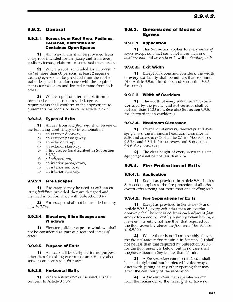
9.9.4.2.
9.9.2. General
9.9.2.1. Egress from Roof Area, Podiums,Terraces, Platforms andContained Open Spaces
1) An access to exit shall be provided fromevery roof intended for occupancy and from everypodium, terrace, platform or contained open space.
2) Where a roof is intended for an occupantload of more than 60 persons, at least 2 separatemeans of egress shall be provided from the roof tostairs designed in conformance with the require-ments for exit stairs and located remote from eachother.
3) Where a podium, terrace, platform orcontained open space is provided, egressrequirements shall conform to the appropriate re-quirements for rooms or suites in Article 9.9.7.3.
9.9.2.2. Types of Exits
1) An exit from any floor area shall be one ofthe following used singly or in combination:
a) an exterior doorway,b) an exterior passageway,c) an exterior ramp,d) an exterior stairway,e) a fire escape (as described in Subsection
3.4.7.),f) a horizontal exit,g) an interior passageway,h) an interior ramp, ori) an interior stairway.
9.9.2.3. Fire Escapes
1) Fire escapes may be used as exits on ex-isting buildings provided they are designed andinstalled in conformance with Subsection 3.4.7.
2) Fire escapes shall not be installed on anynew building.
9.9.2.4. Elevators, Slide Escapes andWindows
1) Elevators, slide escapes or windows shallnot be considered as part of a required means ofegress.
9.9.2.5. Purpose of Exits
1) An exit shall be designed for no purposeother than for exiting except that an exit may alsoserve as an access to a floor area.
9.9.2.6. Horizontal Exits
1) Where a horizontal exit is used, it shallconform to Article 3.4.6.9.
9.9.3. Dimensions of Means ofEgress
9.9.3.1. Application
1) This Subsection applies to every means ofegress except exits that serve not more than onedwelling unit and access to exits within dwelling units.
9.9.3.2. Exit Width
1) Except for doors and corridors, the widthof every exit facility shall be not less than 900 mm.(See Article 9.9.6.4. for doors and Subsection 9.8.3.for stairs.)
9.9.3.3. Width of Corridors
1) The width of every public corridor, corri-dor used by the public, and exit corridor shall benot less than 1 100 mm. (See also Subsection 9.9.5.for obstructions in corridors.)
9.9.3.4. Headroom Clearance
1) Except for stairways, doorways and stor-age garages, the minimum headroom clearance inexits and access to exits shall be 2.1 m. (See Articles9.8.3.4. and 9.8.4.4. for stairways and Subsection9.9.6. for doorways.)
2) The clear height of every storey in a stor-age garage shall be not less than 2 m.
9.9.4. Fire Protection of Exits
9.9.4.1. Application
1) Except as provided in Article 9.9.4.4., thisSubsection applies to the fire protection of all exitsexcept exits serving not more than one dwelling unit.
9.9.4.2. Fire Separations for Exits
1) Except as provided in Sentence (5) andArticle 9.9.8.5., every exit other than an exteriordoorway shall be separated from each adjacent floorarea or from another exit by a fire separation having afire-resistance rating not less than that required forthe floor assembly above the floor area. (See Article9.10.9.10.)
2) Where there is no floor assembly above,the fire-resistance rating required in Sentence (1) shallnot be less than that required by Subsection 9.10.8.for the floor assembly below, but in no case shallthe fire-resistance rating be less than 45 min.
3) A fire separation common to 2 exits shallbe smoke-tight and not be pierced by doorways,duct work, piping or any other opening that mayaffect the continuity of the separation.
4) A fire separation that separates an exitfrom the remainder of the building shall have no
201

9.9.4.2.
openings except those for electrical wiring, noncom-bustible conduit and noncombustible piping that serveonly the exit, and for standpipes, sprinkler piping,exit doorways and wired glass and glass block per-mitted in Article 9.9.4.3.
5) The requirements in Sentence (1) do notapply to an exterior exit passageway provided thepassageway has not less than 50% of its exteriorsides open to the outdoors and is served by an exitstair at each end of the passageway.
9.9.4.3. Wired Glass or Glass Block
(See A-3.1.8.17.(1) in Appendix A.)
1) This Article applies to wired glass indoors, and wired glass or glass block in sidelights,where these are installed in fire separations betweenexit enclosures and floor areas.
r 2) Except as provided in Sentence (3),the combined area of glazing in doors andsidelights shall not exceed 0.8 m2.
3) Where an exit enclosure connects with afloor area through an enclosed vestibule or corridorseparated from the floor area by fire separations hav-ing not less than a 45 min fire-resistance rating, theglazed areas described in Sentence (1) need not belimited as required in Sentence (2).
9.9.4.4. Openings Near Unenclosed ExitStairs and Ramps
1) Where an unenclosed exterior exit stair orramp provides the only means of egress from a suite,and is exposed to fire from openings in the exteriorwalls of another fire compartment, the openings inthe exterior walls of the building shall be protectedwith wired glass in fixed steel frames or glass blockconforming to Articles 9.10.13.5. and 9.10.13.7. whenthe openings in the exterior walls of the building arewithin 3 m horizontally and less than 10 m belowor less than 5 m above the exit stair or ramp.
9.9.4.5. Openings in Exterior Walls of Exits
1) Either openings in exterior walls of an exitor openings in adjacent exterior walls of the buildingthe exit serves shall be protected with wired glass infixed steel frames or glass block installed in accor-dance with Articles 9.10.13.5. and 9.10.13.7., where
a) the exit enclosure has exterior walls thatintersect the exterior walls of the buildingat an angle of less than 135� measured onthe outside of the building, and
b) the openings in the exterior walls of thebuilding are within 3 m horizontally andless than 2 m above the openings in theexterior walls of the exit.
(See Appendix A.)
9.9.4.6. Openings Near Exit Doors
1) Where an exterior exit door in one firecompartment is within 3 m horizontally of an unpro-tected opening in another fire compartment and theexterior walls of these fire compartments intersect atan exterior angle of less than 135�, the opening shallbe protected with wired glass in fixed steel framesor glass block conforming to Articles 9.10.13.5. and9.10.13.7.
9.9.4.7. Stairways in 2 Storey, Group D orE Buildings
1) Where a suite of Group D or E occupancyis located partly on the first storey and partly on thesecond storey, stairways serving the second storey ofthat suite need not be constructed as exit stairs pro-vided,
a) the building is not greater than 2 storeys inbuilding height,
b) the suite is separated from other occu-pancies by at least a 45 min fire separation,
c) the area occupied by the suite is notgreater than 100 m2 per storey,
d) the maximum travel distance from anypoint in the suite to an exterior exit is notgreater than 25 m,
e) the floor assemblies have a fire-resistancerating of not less than 45 min or are ofnoncombustible construction, and
f) the basement and first storey are separatedby a fire separation having a fire-resistancerating of not less than 45 min.
9.9.5. Obstructions and Hazards inMeans of Egress
9.9.5.1. Application
1) This Subsection applies to obstructionsand hazards in every means of egress except thosewithin a dwelling unit or serving not more than onedwelling unit.
9.9.5.2. Occupancies in Public Corridors
1) Where a public corridor or a corridor usedby the public contains an occupancy, such occupancyshall not reduce the unobstructed width of the cor-ridor to less than the required width of the corridor.
9.9.5.3. Obstructions in Public Corridors
1) Except as permitted in Sentence (2), ob-structions located within 1 980 mm of the floor shallnot project horizontally more than 100 mm into exitpassageways, corridors used by the public or publiccorridors in a manner that would create a hazard forvisually impaired persons travelling adjacent towalls.
202

9.10.2.2.
b) principal routes providing access to exit inan open floor area,
c) corridors used by the public,d) underground walkways, ande) public corridors.
2) Emergency lighting required in Sentence(1) shall be provided from a source of energy sepa-rate from the electrical supply for the building.
3) Lighting required in Sentence (1) shall bedesigned to be automatically actuated for a periodof at least 30 min when the electric lighting in theaffected area is interrupted.
4) Illumination from lighting required inSentence (1) shall be provided to average levels ofnot less than 10 lx at floor or tread level.
5) Where incandescent lighting is provided,lighting equal to 1 W/m2 of floor area shall be con-sidered to meet the requirement in Sentence (4).
6) Where self-contained emergency lightingunits are used, they shall conform to CSA C22.2 No.141-M, “Unit Equipment for Emergency Lighting.”
Section 9.10. FireProtection9.10.1. General
9.10.1.1. Support of NoncombustibleConstruction
1) Where an assembly is required to be ofnoncombustible construction and to have afire-resistance rating, it shall be supported by non-combustible construction.
9.10.1.2. Sloped Roofs
1) For the purposes of this Section, roofswith slopes of 60� or more to the horizontal andwhich are adjacent to a room or space intended foroccupancy shall be considered as a wall.
9.10.1.3. Items under Part 3 Jurisdiction
1) Tents, air-supported structures, transformervaults, walkways, elevators and escalators shall con-form to Part 3.
2) Where rooms or spaces are intended foran assembly occupancy, such rooms or spaces shallconform to Part 3.
3) Basements containing more than 1 storeyor exceeding 600 m2 in area shall conform to Part 3.
4) Where rooms or spaces are intended forthe storage, manufacture or use of hazardous orexplosive material, such rooms or spaces shall con-form to Part 3. (See A-3.3.1.2.(1) in Appendix A.)
5) Except as provided in Article 3.3.5.8.,facilities for the dispensing of fuel shall not be in-stalled in any building.
6) Openings through floors that are not pro-tected by shafts or closures shall be protected inconformance with Subsection 3.2.8. (See alsoSentence 9.9.4.7.(1).)
7) Chutes and shafts shall conform toSubsection 3.6.3. except where they are entirely con-tained within a dwelling unit.
8) Where sprinkler, standpipe and hosesystems are installed, they shall be installed in con-formance with Part 3.
9.10.1.4. Items under Part 3 or Part 6 Jurisdiction
1) In kitchens containing commercial cook-ing equipment used in processes producinggrease-laden vapours, the equipment shall be de-signed and installed in conformance with Article6.2.2.6. (See Appendix A.)
2) Where fuel-fired appliances are installedon a roof, such appliances shall be installed in con-formance with Article 3.6.1.4. e
9.10.2. Occupancy Classification
9.10.2.1. Occupancy Classification
1) Except as provided in Article 9.10.2.2.,every building or part thereof shall be classified ac-cording to its major occupancy as belonging to one ofthe groups or divisions described in Table 9.10.2.1.
Table 9.10.2.1.Occupancy Classifications
Forming Part of Sentence 9.10.2.1.(1)
Group Division Description of Major Occupancies(1)
C — Residential occupancies
D — Business and personal servicesoccupancies
E — Mercantile occupancies
F 2 Medium hazard industrial occupancies
F 3 Low hazard industrial occupancies(Does not include storage garagesserving individual dwelling units)
Notes to Table 9.10.2.1.:(1) See A-3.1.2.1. in Appendix A.
9.10.2.2. Custodial and ConvalescentHomes
1) Children’s custodial homes and convales-cent homes for ambulatory occupants living as a
207

9.10.2.2.
single housekeeping unit in a dwelling unit withsleeping accommodation for not more than 10 per-sons are permitted to be classified as residentialoccupancies (Group C).
9.10.2.3. Major Occupancies above OtherMajor Occupancies
1) Except as permitted in Article 9.10.2.4., inany building containing more than one major occu-pancy in which one major occupancy is locatedentirely above another, the requirements of Article9.10.8.1. for each portion of the building containing amajor occupancy shall be applied to that portion as ifthe entire building was of that major occupancy.
9.10.2.4. Buildings Containing More ThanOne Major Occupancy
1) In a building containing more than onemajor occupancy, where the aggregate area of all ma-jor occupancies in a particular group or division doesnot exceed 10% of the floor area on the storey onwhich they are located, they need not be consideredas major occupancies for the purposes of Articles9.10.8.1. and 9.10.2.3. provided they are not classi-fied as Group F, Division 2 occupancies.
9.10.3. Ratings
9.10.3.1. Fire-Resistance andFire-Protection Ratings
1) Where a fire-resistance rating or a fire-protection rating is required in this Section for anelement of a building, such rating shall be deter-mined in conformance with the test methodsdescribed in Part 3, A-9.10.3.1. in Appendix A, orAppendix D.
9.10.3.2. Flame-Spread Ratings
1) Where a flame-spread rating is required inthis Section for an element of a building, such ratingshall be determined in accordance with the testmethods described in Part 3, or in accordance withAppendix D.
2) Unless the flame-spread rating is referredto herein as a “surface flame-spread rating,” it shallapply to any surface of the element being consid-ered that would be exposed by cutting through it aswell as to the exposed surface of the element.
9.10.3.3. Fire Exposure
1) Floor, roof and ceiling assemblies shall berated for exposure to fire on the underside.
2) Exterior walls shall be rated for exposureto fire from inside the building, except that suchwalls need not comply with the temperature rise
limitations required by the standard tests referred toin Article 9.10.3.1. if such walls have a limiting dis-tance of not less than 1.2 m, and due allowance ismade for the effects of heat radiation in accordancewith the requirements in Part 3.
3) Interior vertical fire separations required tohave fire-resistance ratings shall be rated for exposureto fire on each side.
9.10.3.4. Suspended Membrane Ceilings
1) Where a ceiling construction has a sus-pended membrane ceiling with lay-in panels or tileswhich contribute to the required fire-resistance rating,hold down clips or other means shall be providedto prevent the lifting of such panels or tiles in theevent of a fire.
9.10.4. Building Size Determination
9.10.4.1. Mezzanines not Considered asStoreys(See A-3.2.1.1.(3) in Appendix A.)
1) Mezzanines shall not be considered asstoreys for the purpose of determining building heightwhere the aggregate area of mezzanine floors doesnot exceed 10% of the floor area of the storey inwhich they are located.
2) Mezzanines shall not be considered asstoreys for the purpose of determining building heightwhere they occupy an aggregate area of less than40% of the floor area of the storey in which they arelocated provided the space above the mezzaninefloors and the floor below them have no visual ob-structions more than 1 070 mm above such floors.
9.10.4.2. More Than One Level ofMezzanine
1) Where more than one level of mezzanineis provided in a storey, each level additional to thefirst shall be considered as a storey.
9.10.4.3. Basement Storage Garages
1) Where a basement is used primarily as astorage garage, the basement is permitted to be con-sidered as a separate building for the purposes ofthis Section provided the floor above the basementand the exterior walls of the basement above theadjoining ground level are constructed as fire separa-tions of masonry or concrete having a fire-resistancerating of not less than 2 h.
9.10.4.4. Roof-Top Enclosures
1) Roof-top enclosures provided for elevatormachinery, stairways and service rooms, used for nopurpose other than for service to the building, shall
208

9.10.9.9.
211
9.10.9.6. Service Equipment Penetratinga Fire Separation
1) Piping, tubing, ducts, chimneys, wiring,conduit, electrical outlet boxes and other similarservice equipment that penetrate a required fire sep-aration shall be tightly fitted or fire stopped tomaintain the integrity of the separation. (SeeAppendix A.)
2) Except as provided in Sentences (3) to (9)and Article 9.10.9.7., pipes, ducts, electrical boxes,totally enclosed raceways or other similar serviceequipment that partly or wholly penetrate anassembly required to have a fire-resistance ratingshall be noncombustible unless the assembly has beentested incorporating such equipment.
3) Electrical wires or similar wiring en-closed in noncombustible totally enclosed racewaysare permitted to partly or wholly penetrate anassembly required to have a fire-resistance ratingwithout being incorporated in the assembly at thetime of testing as required in Sentence (2).
4) Electrical wires or cables, single orgrouped, with combustible insulation or jacketingthat is not totally enclosed in raceways of noncom-bustible material, are permitted to partly or whollypenetrate an assembly required to have a fire-resistance rating without being incorporated in theassembly at the time of testing as required inSentence (2), provided the overall diameter of thewiring is not more than 25 mm.
5) Combustible totally enclosed racewayswhich are embedded in a concrete floor slab arepermitted in an assembly required to have a fire-resistance rating without being incorporated in theassembly at the time of testing as required inSentence (2), where the concrete provides not lessthan 50 mm of cover between the raceway and thebottom of the slab.
6) Combustible outlet boxes are permitted inan assembly required to have a fire-resistance ratingwithout being incorporated in the assembly at thetime of testing as required in Sentence (2), providedthe opening through the membrane into the boxdoes not exceed 160 cm2.
7) Combustible water distribution piping thathas an outside diameter not more than 30 mm ispermitted to partly or wholly penetrate a verticalfire separation that is required to have a fire-resistancerating without being incorporated in the assembly atthe time of testing as required in Sentence (2) pro-vided the piping is sealed in conformance withArticle 3.1.9.1.
8) Combustible sprinkler piping is permittedto penetrate a fire separation provided the fire com-partments on each side of the fire separation aresprinklered.
9) Combustible piping for central vacuumsystems is permitted to penetrate a fire separationprovided the installation conforms to the require-ments that apply to combustible drain, waste andvent piping specified in Sentences 9.10.9.7.(2) to (6).
9.10.9.7. Combustible Drain, Waste andVent Piping
1) Except as permitted in Sentences (2) to(6), combustible piping shall not be used in any partof a drain, waste and vent piping system where anypart of that system partly or wholly penetrates a fireseparation required to have a fire-resistance rating orpenetrates a membrane that contributes to the re-quired fire-resistance rating of an assembly.
2) Combustible drain, waste and vent pipingnot located in a vertical shaft is permitted to pene-trate a fire separation required to have a fire-resistancerating or a membrane that forms part of an assem-bly required to have a fire-resistance rating providedthe piping is sealed at the penetration by a firestopsystem that has an F rating not less than the fire-resistance rating required for the fire separation.
3) The rating referred to in Sentence (2)shall be based on ULC-S115, “Fire Tests for FireStop Systems,” with a pressure differential of50 Pa between the exposed and unexposed sides,with the higher pressure on the exposed side.
4) Combustible drain piping is permitted topenetrate a horizontal fire separation or a membranethat contributes to the required fire-resistance ratingof a horizontal fire separation, provided it leads di-rectly from a noncombustible watercloset through aconcrete floor slab.
5) Combustible drain, waste and vent pipingis permitted on one side of a vertical fire separationprovided it is not located in a vertical shaft.
6) In buildings containing 2 dwelling unitsonly, combustible drain, waste and vent piping ispermitted on one side of a horizontal fire separation.
9.10.9.8. Collapse of CombustibleConstruction
1) Combustible construction that abuts on oris supported by a noncombustible fire separation shallbe constructed so that its collapse under fire condi-tions will not cause collapse of the fire separation.
9.10.9.9. Reduction in Thickness of FireSeparation by Beams and Joists
1) Where pockets for the support of beamsor joists are formed in a masonry or concrete fireseparation, there shall be left a total thickness ofsolid masonry and/or grout and/or concrete notless than the required equivalent thickness shownfor Type S monolithic concrete in Table D-2.1.1. inAppendix D for the required fire-resistance rating.
r
r

9.10.9.9.
212
9.10.9.10. Concealed Spaces above FireSeparations
1) Except as provided in Sentence (2), a hor-izontal service space or other concealed space locatedabove a required vertical fire separation shall be di-vided at the fire separation by an equivalent fireseparation within the space.
2) Where a horizontal service space or otherconcealed space is located above a required verticalfire separation other than a vertical shaft, such spaceneed not be divided as required in Sentence (1) pro-vided the construction between such space and thespace below is constructed as a fire separation havinga fire-resistance rating not less than that required forthe vertical fire separation, except that where thevertical fire separation is not required to have a fire-resistance rating greater than 45 min, the fire-resistancerating of the ceiling may be reduced to 30 min.
9.10.9.11. Separation of ResidentialOccupancies
1) Except as provided in Sentence (2), resi-dential occupancies shall be separated from all othermajor occupancies by a fire separation having a fire-resistance rating of not less than 1 h.
2) Except as provided in Sentence (3), a ma-jor occupancy classified as a residential occupancy shallbe separated from other major occupancies classifiedas mercantile or medium hazard industrial occupanciesby a fire separation having a fire-resistance rating ofnot less than 2 h.
3) Where not more than 2 dwelling units arelocated in a building containing a mercantile occu-pancy, such mercantile occupancy shall be separatedfrom the dwelling units by a fire separation having notless than 1 h fire-resistance rating.
9.10.9.12. Residential Suites in IndustrialBuildings
1) Not more than one suite of residentialoccupancy shall be contained within a building classi-fied as a Group F, Division 2 major occupancy.
9.10.9.13. Separation of Suites
1) Except as required in Article 9.10.9.14.and as permitted by Sentence (2), each suite in otherthan business and personal services occupancies shall beseparated from adjoining suites by a fire separationhaving a fire-resistance rating of not less than 45 min.
2) In sprinklered buildings, suites of businessand personal services occupancy and mercantile occu-pancy that are served by public corridors conforming
with Sentence 3.3.1.4.(4) are not required to be sepa-rated from each other by fire separations.
9.10.9.14. Separation of Residential Suites
1) Except as provided in Sentences (2) and(3) and Article 9.10.20.2., suites in residential occu-pancies shall be separated from adjacent rooms andsuites by a fire separation having a fire-resistance ratingof not less than 45 min.
2) Sleeping rooms in boarding and lodginghouses where sleeping accommodation is providedfor not more than 8 boarders or lodgers need not beseparated from the remainder of the floor area as re-quired in Sentence (1) where the sleeping roomsform part of the proprietor’s residence and do notcontain cooking facilities.
3) Dwelling units that contain 2 or morestoreys including basements shall be separated fromthe remainder of the building by a fire separation hav-ing a fire-resistance rating of not less than 1 h. (SeeA-3.3.4.4.(1) in Appendix A.)
9.10.9.15. Separation of Public Corridors
1) Except as provided in Sentences (2) and(3), public corridors shall be separated from the re-mainder of the building by a fire separation havingnot less than a 45 min fire-resistance rating.
2) In other than residential occupancies, nofire-resistance rating is required for fire separations be-tween a public corridor and the remainder of thebuilding if
a) the floor area is sprinklered,b) the sprinkler system is electrically super-
vised in conformance with Sentence3.2.4.9.(2), and
c) the operation of the sprinkler system willcause a signal to be transmitted to thefire department in conformance withSentence 3.2.4.7.(4).
3) In other than residential occupancies, no fireseparation is required between a public corridor andthe remainder of the building if
a) the floor area is sprinklered,b) the sprinkler system is electrically super-
vised in conformance with Sentence3.2.4.9.(2),
c) the operation of the sprinkler system willcause a signal to be transmitted to thefire department in conformance withSentence 3.2.4.7.(4), and
d) the corridor exceeds 5 m in width.
9.10.9.16. Separation of Storage Garages
1) Except as provided in Sentences (2) and(3), a storage garage shall be separated from other

9.10.14.6.
9.10.14.2. Area of Exposing Building Face
1) The area of an exposing building face shallbe calculated as the total area of exterior wall facingin one direction on any side of a building measuredfrom the finished ground level to the uppermostceiling, except that where a building is divided byfire separations into fire compartments, the area of ex-posing building face may be calculated for each firecompartment provided such separations have notless than a 45 min fire-resistance rating.
9.10.14.3. Inadequate Fire FightingFacilities
1) Where there is no fire department orwhere a fire department is not organized, trainedand equipped to meet the needs of the community,the limiting distance determined from Article9.10.14.1. or required in Articles 9.10.14.12.,9.10.14.14. and 9.10.14.16., shall be doubled for abuilding that is not sprinklered.
Table 9.10.14.1.Maximum Percentage Area of Unprotected Openings in Exterior Walls
Forming Part of Sentence 9.10.14.1.(1)
Maximum Aggregate Area of Unprotected Openings,% of Exposing Building Face Area
Limiting Distance, mOccupancyClassification of
Building
MaximumArea of
ExposingBuilding Face,
m2Lessthan1.2
1.2 1.5 2.0 4.0 6.0 8.0 10.0 12.0 16.0 20.0 25.0
30 0 7 9 12 39 88 100 — — — — —40 0 7 8 11 32 69 100 — — — — —50 0 7 8 10 28 57 100 — — — — —
100 0 7 8 9 18 34 56 84 100 — — —
Residential,business andpersonal services,and low hazardindustrial Over 100 0 7 7 8 12 19 28 40 55 92 100 —
30 0 4 4 6 20 44 80 100 — — — —40 0 4 4 6 16 34 61 97 100 — — —50 0 4 4 5 14 29 50 79 100 — — —
100 0 4 4 4 9 17 28 42 60 100 — —
Mercantile andmedium hazardindustrial
Over 100 0 4 4 4 6 10 14 20 27 46 70 100
9.10.14.4. Alternate Method of DeterminingLimiting Distance
1) The limiting distance shown in Table9.10.14.1. may be reduced provided it is not lessthan the square root of
a) the aggregate area of unprotected openingsin an exposing building face in residentialoccupancies, business and personal servicesoccupancies and low hazard industrial occu-pancies, and
b) twice the aggregate area of unprotectedopenings in mercantile occupancies andmedium hazard industrial occupancies.
9.10.14.5. Openings in Walls Having aLimiting Distance Less Than1.2 m
1) Openings in a wall having a limitingdistance of less than 1.2 m shall be protected by clo-sures, of other than wired glass or glass block,
whose fire protection rating is in conformance withthe fire-resistance rating required for the wall. (SeeTable 9.10.13.1.)
9.10.14.6. Allowance for Sprinklers andWired Glass or Glass Block(See A-3.2.3.11. in Appendix A.)
1) The maximum area of unprotected open-ings is permitted to be doubled where the building issprinklered provided all rooms, including closets andbathrooms, that are adjacent to the exposing buildingface and that have unprotected openings are sprin-klered, notwithstanding any exemptions in thesprinkler standards referenced in Article 3.2.5.13.
2) The maximum area of unprotectedopenings is permitted to be doubled where the un-protected openings are glazed with wired glass insteel frames or glass blocks as described in Articles9.10.13.5. and 9.10.13.7.
217

9.10.14.7.
9.10.14.7. Exterior Wall Construction forIrregularly-Shaped or Skewed Walls
e 1) Except as provided in Sentence 9.10.14.12.(1),for the purpose of using Table 9.10.14.11.to determine the required type of construction,cladding and fire-resistance rating for an irregularly-shaped or skewed exterior wall,
a) the exposing building face shall be taken asthe projection of the exterior wall onto avertical plane located so that no portionof the exposing building face of the buildingis between the vertical plane and the lineto which the limiting distance is measured,and
b) the permitted area of unprotected openingsshall be determined from Table 9.10.14.1.or Article 9.10.14.4., using the limiting dis-tance measured from this exposing buildingface. (See A-3.2.3.1.(4) in Appendix A.)
9.10.14.8. Percentage of UnprotectedOpenings for Irregularly-Shapedor Skewed Walls
1) For the purpose of using Table 9.10.14.1.to determine the actual percentage of unprotectedopenings permitted in an irregularly-shaped orskewed exterior wall, the location of the exposingbuilding face is permitted to be taken at a verticalplane located so that there are no unprotected open-ings between the vertical plane and the line towhich the limiting distance is measured. (See A-3.2.3.1.(4) in Appendix A.)
9.10.14.9. Storeys at Street Level
1) The exposing building face of a storey thatfaces a street and is at the same level as the street is
permitted to have unlimited unprotected openings ifthe limiting distance is not less than 9 m.
9.10.14.10. Open-Air Storage Garages
1) When a storage garage has all storeys con-structed as open-air storeys, the exposing building faceof such garage is permitted to have unlimited un-protected openings provided the storage garage has alimiting distance of not less than 3 m.
9.10.14.11. Construction of ExposingBuilding Face
1) Except as permitted in Sentence (2) andin Articles 9.10.14.12. to 9.10.14.16., each exposingbuilding face and any exterior wall located above anexposing building face that encloses an attic or roofspace shall be constructed in conformance withTable 9.10.14.11. and Subsection 9.10.8.
2) Cladding installed on exposing buildingfaces and exterior walls located above exposingbuilding faces that enclose an attic or roof space neednot conform to “Type of Cladding Required” inTable 9.10.14.11. provided
a) the limiting distance is not less than 0.6 m,b) the exposing face is constructed with no
unprotected openings, andc) the cladding conforms to Clauses
9.10.14.12.(4)(a) to (d).
218

9.10.14.14.
Table 9.10.14.11.Minimum Construction Requirements for Exposing Building Faces
Forming Part of Sentence 9.10.14.11.(1)
Occupancy Classificationof Building
Maximum Area ofUnprotected Openings
Permitted, % of ExposingBuilding Face Area
Minimum RequiredFire-Resistance
Rating
Type of ConstructionRequired
Type of CladdingRequired
0 – 10 1 h Noncombustible Noncombustible
11 – 25 1 h Combustible ornoncombustible NoncombustibleResidential, business and
personal services, and lowhazard industrial
26 – <100 45 min Combustible ornoncombustible
Combustible ornoncombustible
0 – 10 2 h Noncombustible Noncombustible
11 – 25 2 h Combustible ornoncombustible NoncombustibleMercantile, and medium
hazard industrial
26 – <100 1 h Combustible ornoncombustible
Combustible ornoncombustible
9.10.14.12. Exposing Building Face ofHouses
1) For the purposes of this Article, an expos-ing building face may be considered to be made upof any number of separate portions and the require-ments for fire-resistance rating and cladding materialand the limits on glazed openings for each portionmaybe determined based on the limiting distancefor that portion. (See Appendix A.)
2) Except as required in Article 9.10.14.3.and as provided in Sentence (4), in buildings con-taining only dwelling units in which there is nodwelling unit above another dwelling unit, therequirements of Article 9.10.14.11. do not apply pro-vided that the exposing building face
a) has a fire-resistance rating of not less than45 min where the limiting distance is lessthan 1.2 m, and
b) is clad with noncombustible material wherethe limiting distance is less than 0.6 m.
3) Glazed openings in the exposing buildingface referred to in Sentence (2)
a) shall not be permitted where the limitingdistance is less than 1.2 m, and
b) shall be limited in conformance with therequirements for unprotected openings inArticle 9.10.14.1., where the limiting dis-tance is 1.2 m or greater.
4) Cladding on the exposing building face de-scribed in Sentence (2) may be vinyl when thelimiting distance is less than 0.6 m provided thecladding
a) conforms to Subsection 9.27.13.,
b) is installed directly over 12.7 mm gyp-sum sheathing,
c) has a flame spread rating not greater than25 when tested in accordance withSentence 3.1.12.1.(2), and
d) does not exceed 2 mm in thicknessexclusive of fasteners, joints and local re-inforcements.
9.10.14.13. Combustible Projections
1) Except for buildings containing 1 or 2dwelling units only, combustible projections on the ex-terior of a wall that are more than 1 m aboveground level, such as balconies, platforms, canopies,eave projections and stairs, and that could exposean adjacent building to fire spread, shall not be per-mitted within
a) 1.2 m of a property line or the centrelineof a public way, or
b) 2.4 m of a combustible projection on an-other building on the same property.
9.10.14.14. Detached Garage Serving OneDwelling Unit
1) Except as required in Article 9.10.14.3.,the exposing building face of a garage or accessorybuilding that serves one dwelling unit only and is de-tached from any building shall have a fire-resistancerating of not less than 45 min, except that no fire-resistance rating is required where the limitingdistance is 0.6 m or greater.
2) The exterior cladding of detachedgarages or accessory buildings described in Sentence
219

9.10.14.14.
(1) is not required to be noncombustible regardless ofthe limiting distance.
3) The percentage of window openings per-mitted in the exposing building face of detachedgarages or accessory buildings described in Sentence(1) shall conform to the requirements for unprotectedopenings in Article 9.10.14.1.
4) The requirements for limiting distanceshall not apply between a detached garage or acces-sory building and a dwelling unit where
a) the detached garage or accessory buildingserves only one dwelling unit,
b) the detached garage or accessory buildingis located on the same property as thatdwelling unit, and
c) the dwelling unit served by the detachedgarage or accessory building is the onlymajor occupancy on the property.
9.10.14.15. Heavy Timber and SteelColumns
1) Heavy timber and steel columns need notconform to the requirements of Article 9.10.14.11.provided the limiting distance is not less than 3 m.
9.10.14.16. Low Fire Load Occupancies
1) Except as required in Article 9.10.14.3., inbuildings of 1 storey in building height of noncom-bustible construction classified as low hazard industrialoccupancy which are used only for low fire load occu-pancies such as power generating plants or plantsfor the manufacture or storage of noncombustible ma-terials, non-loadbearing wall components need nothave a minimum fire-resistance rating provided thelimiting distance is 3 m or more.
9.10.15. Fire Stops
9.10.15.1. Required Fire Stops inConcealed Spaces
1) Vertical concealed spaces in interior wallsand exterior walls shall be separated by fire stops
a) one from the other, andb) from horizontal concealed spaces.
2) Horizontal concealed spaces in attics,roof spaces, ceilings, floors, and crawl spaces shallbe separated by fire stops
a) one from the other, andb) from vertical concealed spaces.
3) Fire stops shall be provided at all inter-connections between concealed vertical andhorizontal spaces in interior coved ceilings, dropceilings and soffits where the exposed constructionmaterials within the concealed spaces have a surfaceflame-spread rating greater than 25.
4) Fire stops shall be provided at the topand bottom of each run of stairs where they passthrough a floor containing concealed space in whichthe exposed construction materials within the spacehave a surface flame-spread rating greater than 25.
5) In unsprinklered buildings of combustibleconstruction, every concealed space created by a ceil-ing, roof space or unoccupied attic space shall beseparated by fire stops into compartments
a) not more than 60 m in greatest dimen-sion, and
b) where such space contains exposedconstruction materials having a surfaceflame-spread rating greater than 25, notmore than 300 m2 in area.
6) No dimension of the concealed space de-scribed in Clause (5)(b) shall exceed 20 m. e
7) Concealed spaces in mansard or gambrelstyle roofs, exterior cornices, balconies and canopiesof combustible construction in which the exposedconstruction materials within the space have a sur-face flame-spread rating exceeding 25 shall havevertical fire stops at intervals of not more than 20 mand at points where such concealed spaces extendacross the ends of required vertical fire separations.
9.10.15.2. Required Fire Stops in WallAssemblies
1) Except as permitted in Sentence (2), firestops shall be provided to block off concealedspaces within wall assemblies, including spaces cre-ated by furring,
a) at each floor level,b) at each ceiling level where the ceiling
contributes to part of the required fire-resistance rating, and
c) at other locations within the wall, so thatthe distance between fire stops does notexceed 20 m horizontally and 3 m verti-cally.
2) Fire stops described in Sentence (1) arenot required provided
a) the width of the concealed wall spacedoes not exceed 25 mm,
b) the exposed construction materials withinthe space are noncombustible,
c) the exposed construction materials withinthe space, including insulation, but notincluding wiring, piping or similar ser-vices, have a flame-spread rating of notmore than 25, or
d) the concealed wall space is filled with in-sulation.
9.10.15.3. Fire Stop Materials
1) Fire stops shall be constructed of not lessthan
220

9.12.1.1.
225
9.10.21. Fire Protection for Gasand Electric Ranges
(See A-9.10.21. in Appendix A.)
9.10.21.1. Installation of Ranges
1) Except as required in Sentence (2), natu-ral gas ranges shall be installed in accordance withCAN/CGA-B149.1-M, “Natural Gas InstallationCode.” (See Article 9.34.1.1.)
2) Clearances for gas and electric rangesshall be not less than those provided inArticles 9.10.21.2. and 9.10.21.3.
9.10.21.2. Vertical Clearances
1) Except as provided in Sentence (2),framing, finishes and cabinetry installed directlyabove the location of the range shall be not lessthan 750 mm above the level of range burners orelements.
2) The vertical clearance described inSentence (1) for framing, finishes and cabinetslocated directly above the location of the rangemay be reduced to 600 mm above the level of theelements or burners provided the framing, finishesand cabinets
a) are noncombustible, orb) are protected by
i) asbestos millboard not less than6 mm thick, covered with sheetmetal not less than 0.33 mm thick, or
ii) a metal hood with a 125 mmprojection beyond the framing,finishes and cabinets.
9.10.21.3. Horizontal Clearances
1) Except as provided in Sentences (2) and(3), combustible wall framing, finishes or cabinetswithin 450 mm of the area where the range is to belocated shall be protected above the level of theheating elements or burners by material providingfire resistance not less than that of a 9.5 mmthickness of gypsum board.
2) Counter-top splash boards or backplates that extend above the level of heatingelements or burners need not be protected asdescribed in Sentence (1).
3) Except for cabinetry described inArticle 9.10.21.2., cabinetry located not less than450 mm above the level of the heating elements orburners need not be protected as described inSentence (1).
Section 9.11. SoundControl
9.11.1. Sound Transmission ClassRating (Airborne Sound)
9.11.1.1. Determination of SoundTransmission Class Ratings
1) Sound transmission class ratings shall bedetermined in accordance with ASTM E 413, “Clas-sification for Rating Sound Insulation,” using resultsfrom measurements in accordance with
a) ASTM E 90, “Laboratory Measurement ofAirborne Sound Transmission Loss ofBuilding Partitions and Elements,” or
b) ASTM E 336, “Measurement of AirborneSound Insulation in Buildings.”
(See Appendix A.)
9.11.2. Required Sound ControlLocations (Airborne Sound)
9.11.2.1. Minimum Sound TransmissionClass Ratings
1) Except as provided in Sentence (2), everydwelling unit shall be separated from every other spacein a building in which noise may be generated by aconstruction providing a sound transmission classrating of at least 50, measured in accordance withSubsection 9.11.1. or as listed in A-9.10.3.1. inAppendix A.
2) Where a dwelling unit is adjacent to anelevator shaft or a refuse chute, the separatingconstruction shall have a sound transmission classrating of at least 55, measured in accordance withSubsection 9.11.1. or as listed in A-9.10.3.1. inAppendix A.
Section 9.12. Excavation
9.12.1. General
9.12.1.1. Removal of Topsoil and OrganicMatter
1) The topsoil and vegetable matter in allunexcavated areas under a building shall be removed.
r

9.12.1.1.
2) In localities where termite infestation isknown to be a problem, all stumps, roots and otherwood debris shall be removed from the soil to adepth of not less than 300 mm in unexcavated areasunder a building.
3) The bottom of every excavation shall befree of all organic material.
9.12.1.2. Standing Water
1) Excavations shall be kept free of standingwater.
9.12.1.3. Protection from Freezing
1) The bottom of excavations shall be keptfrom freezing throughout the entire construction pe-riod.
9.12.2. Depth
9.12.2.1. Excavation to Undisturbed Soil
1) Excavations for foundations shall extend toundisturbed soil.
9.12.2.2. Minimum Depth of Foundations
1) Except as provided in Sentences (4) and(5), the minimum depth of foundations below fin-ished ground level shall conform to Table 9.12.2.2.
2) Where a foundation is insulated in a man-ner that will reduce heat flow to the soil beneath thefootings, the foundation depth shall conform to thatrequired for foundations containing no heated space.(See Appendix A.)
3) The minimum depth of foundations for ex-terior concrete steps with more than 2 risers shallconform to Sentences (1) to (5).
4) Concrete steps with 1 and 2 risers arepermitted to be laid on ground level.
5) The foundation depths required inSentence (1) are permitted to be decreased whereexperience with local soil conditions shows thatlesser depths are satisfactory, or where the founda-tion is designed for lesser depths.
6) The foundation depths required inSentence (1) do not apply to foundations for buildingsof other than masonry or masonry veneerconstruction
a) whose superstructure conforms with therequirements of the deformation resis-tance test in CAN/CSA-Z240.2.1,“Structural Requirements for MobileHomes,” or
b) used as accessory buildings of not morethan 1 storey in building height and notmore than 55 m2 in building area.
Table 9.12.2.2.Minimum Depths of Foundations
Forming Part of Sentence 9.12.2.2.(1)
Minimum Depth of Foundation Containing HeatedBasement or Crawl Space(1)
Minimum Depth of Foundation Containing No HeatedSpace(2)
Type of Soil
Good Soil Drainage(3) Poor Soil Drainage Good Soil Drainage(3) Poor Soil Drainage
Rock No limit No limit No limit No limit
Coarse grainedsoils No limit No limit No limit Below the depth of frost
penetration
Silt No limit No limit Below the depth of frostpenetration
Below the depth of frostpenetration
Clay or soils notclearly defined(4) 1.2 m 1.2 m
1.2 m but not less thanthe depth of frost
penetration
1.2 m but not less thanthe depth of frost
penetration
Notes to Table 9.12.2.2.:(1) Foundation not insulated to reduce heat loss through the footings.(2) Including foundations insulated to reduce heat loss through the footings.(3) To not less than the depth of frost penetration.(4) See Appendix A.
226
9.13.2.1.
9.12.3. Backfill
9.12.3.1. Placement of Backfill
1) Backfill shall be placed to avoid damag-ing the foundation wall, the drainage tile, externallyapplied thermal insulation and waterproofing ordampproofing of the wall.
9.12.3.2. Grading of Backfill
1) Backfill shall be graded to preventdrainage towards the foundation after settling.
9.12.3.3. Deleterious Debris and Boulders
1) Backfill within 600 mm of the foundationshall be free of deleterious debris and boulderslarger than 250 mm diam.
9.12.4. Trenches beneath Footings
9.12.4.1. Support of Footings
1) The soil in trenches beneath footings forsewers and watermains shall be compacted bytamping up to the level of the footing base, or shallbe filled with concrete having a strength not lessthan 10 MPa to support the footing.
Section 9.13.Dampproofing,Waterproofing and SoilGas Control9.13.1. General
9.13.1.1. Required Dampproofing
1) Except as provided in Article 9.13.1.2.,where the exterior finished ground level is at ahigher elevation than the ground level inside thefoundation walls, exterior surfaces of foundation wallsbelow ground level shall be dampproofed.
2) Except as provided in Sentence (3) andArticle 9.13.1.2., floors-on-ground shall be damp-proofed.
3) Floors in garages, floors in unenclosedportions of buildings and floors installed over granu-lar fill in conformance with Article 9.16.2.1. need notbe dampproofed.
9.13.1.2. Required Waterproofing
1) Where hydrostatic pressure occurs,floors-on-ground and exterior surfaces of walls be-low ground level shall be waterproofed.
2) Roofs of underground structures shall bewaterproofed to prevent the entry of water into thestructure.
9.13.1.3. Required Soil Gas Control(See Appendix A.)
1) Except as provided in Sentence (2), allwall, roof and floor assemblies in contact with theground shall be constructed to resist the leakage ofsoil gas from the ground into the building.
2) Construction to resist leakage of soil gasinto the building is not required for
a) garages and unenclosed portions of build-ings,
b) buildings constructed in areas where itcan be demonstrated that soil gas doesnot constitute a hazard, or
c) buildings that contain a single dwellingunit and are constructed to provide forsub-floor depressurization in accordancewith Article 9.13.8.2.
9.13.1.4. Standards for Application
1) The method of application of all bitumi-nous waterproofing and dampproofing materialsshall conform to
a) CAN/CGSB-37.3-M, “Application ofEmulsified Asphalts for Dampproofing orWaterproofing,”
b) CGSB 37-GP-12Ma, “Application ofUnfilled Cutback Asphalt for Damp-proofing,” or
c) CAN/CGSB-37.22-M, “Application ofUnfilled Cutback Tar Foundation Coatingfor Dampproofing.”
9.13.2. Material
9.13.2.1. Material Standards
1) Except as otherwise specified in thisSection, materials used for exterior dampproofing orwaterproofing shall conform to
a) CAN/CGSB-37.1-M, “Chemical Emulsi-fied Type, Emulsified Asphalt forDampproofing,”
b) CAN/CGSB-37.2-M, “Emulsified Asphalt,Mineral-Colloid Type, Unfilled, forDampproofing and Waterproofing andfor Roof Coatings,”
c) CGSB 37-GP-6Ma, “Asphalt, Cutback,Unfilled, for Dampproofing,”
d) CAN/CGSB-37.16-M, “Filled CutbackAsphalt for Dampproofing and Water-proofing,”
e) CGSB 37-GP-18Ma, “Tar, Cutback, Un-filled, for Dampproofing,”
227

9.13.2.1.
f) CAN/CGSB-51.34-M, “Vapour Barrier,Polyethylene Sheet for Use in BuildingConstruction,” or
g) CSA A123.4-M, “Bitumen for Use inConstruction of Built-Up Roof Coveringsand Dampproofing and WaterproofingSystems.”
2) Materials used to provide a barrier to soilr gas ingress through floors-on-ground shall conform to
CAN/CGSB-51.34-M,“Vapour Barrier, PolyethyleneSheet for Use in Building Construction.”
9.13.3. Dampproofing of Walls
9.13.3.1. Preparation of Surface
1) Unit masonry walls to be dampproofedshall be
a) parged on the exterior face below groundlevel with not less than 6 mm of mortarconforming to Section 9.20., and
b) coved over the footing when the firstcourse of block is laid.
2) Concrete walls to be dampproofed shallhave holes and recesses resulting from the removalof form ties sealed with cement mortar or damp-proofing material.
9.13.3.2. Application of DampproofingMaterial
1) Dampproofing material shall be appliedover the parging or concrete below ground level.
9.13.3.3. Interior Dampproofing of Walls
1) Where a separate interior finish is ap-plied to a concrete or unit masonry wall which is incontact with the soil, or where wood members areplaced in contact with such walls for the installationof insulation or finish, the interior surface of thefoundation wall below ground level shall be damp-proofed.
2) The dampproofing required in Sentence(1) shall extend from the basement floor and termi-nate at ground level.
3) No membrane or coating with a perme-e ance less than 170 ng/(Pa•s•m 2) shall be applied
to the interior surface of the foundation wall aboveground level between the insulation and the founda-tion wall.
9.13.4. Dampproofing ofFloors-on-Ground
9.13.4.1. Location of Dampproofing
1) When floors are dampproofed, the damp-proofing shall be installed below the floor, exceptthat where a separate floor is provided over a slab,
the dampproofing is permitted to be applied to thetop of the slab.
9.13.4.2. Dampproofing below the Floor
1) When installed below the floor, damp-proofing membranes shall consist of polyethylenenot less than 0.15 mm thick, or type S roll roofing.
2) Joints in dampproofing membranes de-scribed in Sentence (1) shall be lapped not less than100 mm.
9.13.4.3. Dampproofing above the Slab
1) When installed above the slab, damp-proofing shall consist of not less than
a) 2 mopped-on coats of bitumen,b) 0.05 mm polyethylene, orc) other material providing equivalent per-
formance.
9.13.5. Waterproofing of Walls
9.13.5.1. Preparation of Surface
1) Unit masonry walls to be waterproofedshall be parged on exterior surfaces below groundlevel with not less than 6 mm of mortar conformingto Section 9.20.
2) Concrete walls to be waterproofed shallhave all holes and recesses resulting from removalof form ties sealed with mortar or waterproofingmaterial.
9.13.5.2. Application of WaterproofingMembranes
1) Concrete or unit masonry walls to be wa-terproofed shall be covered with not less than 2layers of bitumen-saturated membrane, with eachlayer cemented in place with bitumen and coatedover-all with a heavy coating of bitumen.
9.13.6. Waterproofing ofFloors-on-Ground
9.13.6.1. Floor Waterproofing System
1) Basement floors-on-ground to be water-proofed shall have a system of membranewaterproofing provided between 2 layers of con-crete, each of which shall be not less than 75 mmthick, with the floor membrane mopped to the wallmembrane to form a complete seal.
228

9.13.8.3.
9.13.7. Soil Gas Control in Walls(See A-9.13.7. and 9.13.8. in Appendix A.)
9.13.7.1. Sealing of Masonry Walls
1) Masonry walls required to provide a bar-rier to soil gas and which are not dampproofed ontheir interior surface as required in Sentence9.13.3.3.(1) shall
a) include a course of masonry units with-out voids, or
b) be sealed with flashing material extend-ing across the full width of the masonry
i) at or below the level of the adjoin-ing floor slab, or
ii) in the absence of a floor slab, at thelevel of the ground cover requiredin Article 9.18.6.1.
9.13.8. Soil Gas Control in Floors(See A-9.13.7. and 9.13.8. in Appendix A.)
9.13.8.1. Soil Gas Barriers
1) Except as provided in Article 9.13.8.2., asoil gas barrier shall be installed.
2) Where the floor-on-ground is a concreteslab, the soil gas barrier shall be
a) installed below the slab, orb) applied to the top of the slab, provided a
separate floor is installed over the slab.(See A-9.13.8.1.(2) and (3) in Appendix A.)
3) When the soil gas barrier is installed be-low a slab-on-ground, joints in the barrier shall belapped not less than 300 mm. (See A-9.13.8.1.(2) and(3) in Appendix A.)
4) When the soil gas barrier is installedabove a slab-on-ground, joints in the barrier shall besealed.
5) When installed in conjunction with aframed floor-on-ground, the soil gas barrier shall beinstalled in accordance with Articles 9.25.3.2. and9.25.3.3.
9.13.8.2. Providing for Sub-FloorDepressurization(See Appendix A.)
1) A soil gas barrier is permitted to be omit-ted provided the building,
a) contains a single dwelling unit only, andb) is protected against soil gas ingress ac-
cording to the requirements of thisArticle.
2) Except as required in Sentence (4),granular material shall be installed below the floor-on-ground according to Sentence 9.16.2.1.(1).
3) A pipe, not less than 100 mm in diame-ter, shall be installed vertically through the floor, ator near its centre, such that
a) its bottom end opens into the granular filldescribed in Sentence (2), and
b) its top end will permit connection to de-pressurization equipment.
4) The granular material described inSentence (2), near the centre of the floor, shall benot less than 150 mm deep for a radius of not lessthan 300 mm centred on the pipe described inSentence (3).
5) The upper end of the pipe described inSentence (3) shall be provided with a removableseal.
6) The pipe described in Sentence (3) shallbe clearly labelled to indicate that it is intendedonly for the removal of soil gas from below thefloor-on-ground.
7) Except as provided in Sentence (9), when ea building constructed in accordance with Sentences(2) to (6) is complete, testing shall be conducted ac-cording to the U.S. Environmental ProtectionAgency standard EPA 402-R-92-003, “Protocols forRadon and Radon Decay Product Measurements inHomes,” to determine the radon concentration in thebuilding.
8) A copy of the results of testing requiredin Sentence (7) shall be provided by the buildingowner to the authority having jurisdiction.
9) The testing required in Sentence (7) shallinclude basement concentration measurements.
10) Where the radon concentration deter-mined as described in Sentences (7) and (9) exceedsthe Canadian Action Level for radon in residentialindoor air, as specified in HC H 49-58, “ExposureGuidelines for Residential Indoor Air Quality,” asub-floor depressurization system shall be installedto reduce the radon concentration to a level belowthe Canadian Action Level.
11) Where a sub-floor depressurization sys-tem is installed,
a) make-up air shall be provided when andas specified in accordance with Article9.32.3.8., and
b) measures shall be taken to ensure thatany resultant decrease in soil temperaturewill not adversely affect the foundation.
9.13.8.3. Sealing of the Perimeter andPenetrations(See A-9.13.7. and 9.13.8. in Appendix A.)
1) A floor-on-ground shall be sealed aroundits perimeter to the inner surfaces of adjacent wallsusing flexible sealant.
229

9.13.8.3.
2) All penetrations of a floor-on-ground bypipes or other objects shall be sealed against soil gasleakage.
3) All penetrations of a floor-on-groundwhich are required to drain water from the floorsurface shall be sealed in a manner which preventsthe upward flow of soil gas without preventing thedownward flow of liquid water.
Section 9.14. Drainage9.14.1. Scope
9.14.1.1. Application
1) This Section applies to subsurfacedrainage and to surface drainage.
9.14.1.2. Crawl Spaces
1) Drainage for crawl spaces shall conformto Section 9.18.
9.14.1.3. Floors-on-Ground
1) Drainage requirements beneath floors-on-ground shall conform to Section 9.16.
9.14.2. Foundation Drainage
9.14.2.1. Foundation Wall Drainage
1) Unless it can be shown to be unneces-sary, the bottom of every exterior foundation wallshall be drained by drainage tile or pipe laidaround the exterior of the foundation in conformancewith Subsection 9.14.3. or by a layer of gravel orcrushed rock in conformance with Subsection 9.14.4.
2) Where mineral fibre insulation or crushedrock backfill is provided adjacent to the exterior sur-face of a foundation wall, it shall extend to thefooting level to facilitate drainage of ground waterto the foundation drainage system. (See Appendix A.)
9.14.3. Drainage Tile and Pipe
9.14.3.1. Material Standards
1) Drain tile and drain pipe for foundationdrainage shall conform to
a) ASTM C 4, “Clay Drain Tile,”b) ASTM C 412M, “Concrete Drain Tile
(Metric),”c) ASTM C 444M, “Perforated Concrete
Pipe (Metric),”d) ASTM C 700, “Vitrified Clay Pipe, Extra
Strength, Standard Strength and Perfo-rated,”
r e) CAN/CGSB-34.22, “Asbestos-CementDrain Pipe,”
f) CSA B182.1, “Plastic Drain and rSewer Pipe and Pipe Fittings,”
g) CSA G401, “Corrugated Steel Pipe Prod-ucts,” or
h) NQ 3624-115, “Thermo-Plastic Pipe –Flexible Corrugated Tubing and Fittingsfor Soil Drainage.”
9.14.3.2. Minimum Size
1) Drain tile or pipe used for foundationdrainage shall be not less than 100 mm in diam.
9.14.3.3. Installation
1) Drain tile or pipe shall be laid on undis-turbed or well-compacted soil so that the top of thetile or pipe is below the bottom of the floor slab orcrawl space.
2) Drain tile or pipe with butt joints shall belaid with 6 mm to 10 mm open joints.
3) The top half of joints referred to inSentence (2) shall be covered with sheathing paper,0.10 mm polyethylene or No. 15 asphalt or tar-saturated felt.
4) The top and sides of drain pipe or tileshall be covered with not less than 150 mm ofcrushed stone or other coarse clean granular mate-rial containing not more than 10% of material thatwill pass a 4 mm sieve.
9.14.4. Granular Drainage Layer
9.14.4.1. Type of Granular Material
1) Granular material used to drain the bot-tom of a foundation shall consist of a continuouslayer of crushed stone or other coarse clean granu-lar material containing not more than 10% ofmaterial that will pass a 4 mm sieve.
9.14.4.2. Installation
1) Granular material described in Article9.14.4.1. shall be laid on undisturbed or compactedsoil to a minimum depth of not less than 125 mmbeneath the building and extend not less than300 mm beyond the outside edge of the footings.
9.14.4.3. Grading
1) The bottom of an excavation drained by agranular layer shall be graded so that the entirearea described in Article 9.14.4.2. is drained to asump conforming to Article 9.14.5.2.
9.14.4.4. Wet Site Conditions
1) Where because of wet site conditions soilbecomes mixed with the granular drainage material,
230

9.15.4.3.
233
e
footing width shall be not less than twice the widthrequired by Article 9.15.3.3.
9.15.3.5. Non-Loadbearing Walls
1) Footings for interior non-loadbearing ma-sonry walls shall be not less than 200 mm wide forwalls up to 5.5 m high and shall be increased by100 mm for each additional 2.7 m of height.
9.15.3.6. Thickness
1) Footings shall be not less than 100 mmthick except when greater thicknesses are requiredbecause of the projection of the footing beyond thesupported element.
9.15.3.7. Footing Projection
1) The projection of an unreinforced footingbeyond the supported element shall be not greaterthan the thickness of the footing.
9.15.3.8. Step Footings
1) When step footings are used,a) the vertical rise between horizontal por-
tions shall not exceed 600 mm, andb) the horizontal distance between risers
shall not be less than 600 mm.
9.15.4. Foundation Walls
9.15.4.1. Foundation Wall Thickness
1) Where average stable soils are encoun-tered, the thickness of foundation walls subject tolateral earth pressure shall conform to Table9.15.4.1. for walls not exceeding 2.5 m in unsup-ported height.
Table 9.15.4.1.Thickness of Foundation Walls
Forming Part of Sentence 9.15.4.1.(1)
Maximum Height of FinishGround Above Basement Flooror Crawl Space Ground Cover,
mType of
FoundationWall
MinimumWall
Thickness,mm
FoundationWall LaterallyUnsupportedat the Top (1)
FoundationWall LaterallySupported at
the Top (1)
150 0.80 1.50200 1.20 2.15250 1.40 2.30
Solidconcrete,
15 MPa min.strength
300 1.50 2.30150 0.80 1.80200 1.20 2.30250 1.40 2.30
Solidconcrete,
20 MPa min.strength
300 1.50 2.30140 0.60 0.80190 0.90 1.20240 1.20 1.80
Unit masonry
290 1.40 2.20
Notes to Table 9.15.4.1.:(1) See Article 9.15.4.2.
9.15.4.2. Lateral Support
1) For the purposes of Article 9.15.4.1., foun-dation walls shall be considered laterally supportedat the top if such walls support solid masonry su-perstructure or if the floor joists are embedded inthe top of the foundation walls.
2) Foundation walls shall also be consideredsupported at the top if the floor system is anchoredto the top of the foundation walls with anchor bolts,in which case the joists may run either parallel orperpendicular to the foundation wall.
3) When a foundation wall contains an open-ing more than 1.2 m long or contains openings inmore than 25% of its length, that portion of the wallbeneath such openings shall be considered laterallyunsupported, unless the wall around the opening isreinforced to withstand the earth pressure.
4) When the length of solid wall betweenwindows is less than the average length of the win-dows, the combined length of such windows shallbe considered as a single opening for the purposesof Sentence (3).
9.15.4.3. Extension above Ground Level
1) Exterior foundation walls shall extend notless than 150 mm above finished ground level.

9.15.4.4.
9.15.4.4. Reduction in Thickness
1) Where the top of a foundation wall is re-duced in thickness to permit the installation of floorjoists, the reduced section shall be not more than350 mm high and not less than 90 mm thick.
2) Where the top of a foundation wall is re-duced in thickness to permit the installation of amasonry exterior facing, the reduced section shall be
a) not less than 90 mm thick, andb) tied to the facing material with metal ties
conforming to Article 9.20.9.4.(3) spacednot more than
i) 200 mm o.c. vertically, andii) 900 mm o.c. horizontally.
3) The space between wall and facing de-scribed in Sentence (2) shall be filled with mortar.
9.15.4.5. Corbelling
1) Corbelling of masonry foundation wallssupporting cavity walls shall conform to Article9.20.12.2.
9.15.4.6. Crack Control Joints
1) Crack control joints shall be provided infoundation walls more than 25 m long at intervals ofnot more than 15 m.
2) Joints required in Sentence (1) shall bedesigned to resist moisture penetration and shall bekeyed to prevent relative displacement of the wallportions adjacent to the joint.
9.15.4.7. Interior Masonry Walls
1) Interior masonry foundation walls notsubject to lateral earth pressure shall conform toSection 9.20.
9.15.5. Support of Joists and Beamson Masonry FoundationWalls
9.15.5.1. Support of Floor Joists
1) Except as permitted in Sentence (2), foun-dation walls of hollow masonry units supportingfloor joists shall be capped with not less than50 mm of solid masonry or concrete, or have thetop course filled with mortar or concrete.
2) Capping required in Sentence (1) neednot be provided
a) in localities where termites are notknown to occur,
b) when the joists are supported on a woodplate not less than 38 mm by 89 mm, and
c) when the siding overlaps the foundationwall not less than 12 mm.
9.15.5.2. Support of Beams
1) Not less than 190 mm depth of solid ma-sonry shall be provided beneath beams supportedon masonry.
2) Where the beam referred to in Sentence(1) is supported below the top of the foundationwalls, the ends of such beams shall be protectedfrom the weather.
9.15.5.3. Pilasters
1) Pilasters shall be provided under beamsthat frame into unit masonry foundation walls140 mm or less in thickness.
2) Pilasters required in Sentence (1) shall benot less than 90 mm by 290 mm and shall bebonded or tied into the wall.
3) The top 200 mm of pilasters required inSentence (1) shall be solid.
9.15.6. Parging and Finishing ofMasonry Foundation Walls
9.15.6.1. Foundation Walls below Ground
1) Concrete block foundation walls shall beparged on the exterior face below ground level asrequired in Section 9.13.
9.15.6.2. Foundation Walls above Ground
1) Exterior surfaces of concrete block founda-tion walls above ground level shall have tooledjoints, or shall be parged or otherwise suitably fin-ished.
9.15.6.3. Form Ties
1) All form ties shall be removed at leastflush with the concrete surface.
Section 9.16.Floors-On-Ground9.16.1. Scope
9.16.1.1. Application
1) This Section applies to floors supportedon ground or on granular fill which do not providestructural support for the superstructure.
9.16.1.2. Structural Floors
1) Floors-on-ground that support loadsfrom the superstructure shall be designed in confor-mance with Part 4.
234

9.17.2.1.
235
9.16.1.3. Required Floors-on-Ground
1) All spaces within dwelling units, exceptcrawl spaces, shall be provided with a floor-on-ground, where
a) access is provided to the space, andb) a floor supported by the structure is not
provided.
9.16.1.4. Dampproofing and Waterproofing
1) Dampproofing and waterproofing shallconform to Section 9.13.
9.16.2. Material beneath Floors
9.16.2.1. Required Installation of GranularMaterial
1) Except as provided in Sentence (2), notless than 100 mm of coarse clean granular materialcontaining not more than 10% of material that willpass a 4 mm sieve shall be placed beneath floors-on-ground. (See Clause 9.13.1.3.(2)(c), Article 9.13.8.2.,and A-9.13.1.3. and A-9.13.8.2. in Appendix A.)
2) Granular material need not be installedunder
a) slabs in garages, carports or accessorybuildings,
b) buildings of industrial occupancy where thenature of the process contained thereinpermits or requires the use of large open-ings in the building envelope even duringthe winter, or
c) buildings constructed in areas where itcan be demonstrated that soil gas doesnot constitute a hazard.
9.16.2.2. Support of Floors
1) Except as provided in Sentence (2), fillbeneath floors-on-ground shall be compacted.
2) Fill beneath floors-on-ground need not becompacted where the material is clean coarseaggregate containing not more than 10% of materialthat will pass a 4 mm sieve.
9.16.3. Drainage
9.16.3.1. Control of Water Ingress
1) Except as provided in Article 9.16.3.2. orwhere it can be shown to be unnecessary, ingress ofwater underneath a floor-on-ground shall be pre-vented by grading or drainage.
9.16.3.2. Hydrostatic Pressure
1) Where ground water levels may causehydrostatic pressure beneath a floor-on-ground, thefloor-on-ground shall be
a) a poured concrete slab, andb) designed to resist such pressures.
9.16.3.3. Floor Drains
1) When floor drains are required (see Section9.31.), the floor surface shall be sloped so that nowater can accumulate.
9.16.4. Concrete
9.16.4.1. Surface Finish
1) The finished surface of concrete floor slabsshall be trowelled smooth and even.
2) Dry cement shall not be added to the floorsurfaces to absorb surplus water.
9.16.4.2. Topping Course
1) When a topping course is provided for aconcrete floor slab, it shall consist of 1 part cement to2.5 parts clean, well graded sand by volume, with awater/cement ratio approximately equal to that ofthe base slab.
2) When concrete topping is provided, it shallnot be less than 20 mm thick.
9.16.4.3. Thickness
1) Concrete slabs shall not be less than 75 mmthick exclusive of concrete topping.
9.16.4.4. Bond Break
1) A bond-breaking material shall be placedbetween the slab and footings or rock.
9.16.5. Wood
9.16.5.1. Wood Frame Floors
1) Floors-on-ground constructed of woodshall conform to CAN/CSA-S406, “Construction ofPreserved Wood Foundations.”
Section 9.17. Columns9.17.1. Scope
9.17.1.1. Application
1) This Section applies to columns used tosupport carport roofs (see Section 9.35.) and beamscarrying loads from not more than 2 wood-framefloors where the supported length of joists bearing onsuch beams does not exceed 5 m and the live load onany floor does not exceed 2.4 kPa. (See Table 4.1.6.3.)
2) Columns for applications other than asdescribed in Sentence (1) shall be designed in accor-dance with Part 4.
9.17.2. General
9.17.2.1. Location
1) Columns shall be centrally located on afooting conforming to Section 9.15.
r
r

9.17.2.2.
9.17.2.2. Fastening
1) Columns shall be securely fastened to thesupported member to prevent lateral movement.
9.17.3. Steel Columns
9.17.3.1. Size and Thickness
1) Except as permitted in Sentence (2), steelpipe columns shall have an outside diameter of notless than 73 mm and a wall thickness of not lessthan 4.76 mm.
2) Columns of sizes other than as specifiedin Sentence (1) are permitted to be used where theloadbearing capacities are shown to be adequate.
9.17.3.2. End Bearing Plates
1) Except as permitted in Sentence (2), steelcolumns shall be fitted with not less than 100 mmby 100 mm by 6.35 mm thick steel plates at eachend, and where the column supports a woodenbeam, the top plate shall extend across the fullwidth of the beam.
2) The top plate required in Sentence (1)need not be provided where a column supports asteel beam and provision is made for the attach-ment of the column to the beam.
9.17.3.3. Paint
1) Steel columns shall be treated on the out-side surface with at least one coat of rust-inhibitivepaint.
9.17.3.4. Adjustable Steel Columns
1) Adjustable steel columns shall conform toCAN/CGSB-7.2, “Adjustable Steel Columns.”
9.17.4. Wood Columns
9.17.4.1. Column Sizes
1) The width or diameter of a wood columnshall be not less than the width of the supportedmember.
2) Except as provided in Article 9.35.4.2.,columns shall be not less than 184 mm for roundcolumns and 140 mm by 140 mm for rectangularcolumns, unless calculations are provided to showthat lesser sizes are adequate.
9.17.4.2. Materials
1) Wood columns shall be either solid,glued-laminated or built-up.
2) Built-up columns shall consist of not lessthan 38 mm thick full-length members
a) bolted together with not less than9.52 mm diam bolts spaced not morethan 450 mm o.c., or
b) nailed together with not less than 76 mmnails spaced not more than 300 mm o.c.
3) Glued-laminated columns shall conformto Section 4.3.
9.17.4.3. Columns in Contact with Concrete
1) Wood columns shall be separated fromconcrete in contact with the ground by 0.05 mmpolyethylene film or Type S roll roofing.
9.17.5. Unit Masonry Columns
9.17.5.1. Materials
1) Unit masonry columns shall be built ofmasonry units
a) conforming to CSA A165.1, “Con-crete Masonry Units,” and
b) having a compressive strength over thenet area of the block of not less than15 MPa.
9.17.5.2. Sizes
1) Unit masonry columns shall be not lessthan 290 mm by 290 mm or 240 mm by 380 mm insize.
9.17.6. Solid Concrete Columns
9.17.6.1. Materials
1) Concrete shall conform to Section 9.3.
9.17.6.2. Sizes
1) Concrete columns shall be not less than200 mm by 200 mm for rectangular columns and230 mm diam for circular columns.
Section 9.18. CrawlSpaces9.18.1. General
9.18.1.1. Application
1) This Section applies to crawl spaceswhose exterior walls have less than 25% of their to-tal area above exterior ground level open to theoutdoors.
9.18.1.2. Foundations
1) Foundations enclosing crawl spaces shallconform to Section 9.15.
236

9.18.6.2.
9.18.1.3. Heated and Unheated CrawlSpaces
1) Crawl spaces shall be considered to beheated where the space
a) is used as a hot air plenum,b) contains heating ducts that are not sealed
and insulated to minimize heat loss tothe space, or
c) is not separated from heated space in ac-cordance with Section 9.25.
2) Heating of heated crawl spaces shall con-form to Section 9.33.
3) Insulation, an air barrier system and avapour barrier shall be installed in the walls ofheated crawl spaces in accordance with Section 9.25.
9.18.2. Access
9.18.2.1. Access Openings
1) An access opening of not less than500 mm by 700 mm shall be provided to each crawlspace where the crawl space serves a single dwellingunit, and not less than 550 mm by 900 mm for othercrawl spaces.
2) Access openings shall be fitted with adoor or hatch, except when the crawl space isheated and the access opening into the crawl spaceis from an adjacent heated space.
9.18.3. Ventilation
9.18.3.1. Ventilation of Unheated CrawlSpaces
1) Unheated crawl spaces shall be ventilatedby natural or mechanical means.
2) Where an unheated crawl space is venti-lated by natural means, ventilation shall beprovided to the outside air by not less than 0.1 m2 ofunobstructed vent area for every 50 m2 of floor area.
3) Vents shall bea) uniformly distributed on opposite sides
of the building, andb) designed to prevent the entry of snow,
rain and insects.
9.18.3.2. Ventilation of Heated CrawlSpaces
1) Heated crawl spaces shall be ventilatedin accordance with Section 9.32.
9.18.4. Clearance(See also Article 9.3.2.9.)
9.18.4.1. Access Way to Services
1) Where equipment requiring service suchas plumbing cleanouts, traps and burners is locatedin crawl spaces, an access way with a height andwidth of not less than 600 mm shall be providedfrom the access door to the equipment and for adistance of 900 mm on the side or sides of theequipment to be serviced.
9.18.5. Drainage
9.18.5.1. Drainage
1) Except where it can be shown to be un-necessary, the ingress of water into a crawl spaceshall be controlled by grading or drainage.
2) Drainage of foundation walls shall con-form to Article 9.14.2.1.
3) Drainage of the ground cover or floor-on-ground in the crawl space shall conform to Subsection e9.16.3.
4) Drains shall conform to Section 9.14.
9.18.6. Ground Cover
9.18.6.1. Ground Cover in Unheated CrawlSpaces
1) Where a crawl space is unheated, aground cover shall be provided consisting of notless than
a) 50 mm of asphalt,b) 100 mm of 15 MPa Portland cement con-
crete,c) Type S roll roofing, ord) 0.10 mm polyethylene.
2) Joints in sheet-type ground cover re-quired in Sentence (1) shall be lapped not less than100 mm and weighted down.
9.18.6.2. Ground Cover in Heated CrawlSpaces
1) Where a crawl space is heated, a groundcover consisting of not less than 0.15 mm poly-ethylene sheet conforming to CAN/CGSB-51.34-M,“Vapour Barrier, Polyethylene Sheet for Use inBuilding Construction,” shall be provided.
2) The ground cover required in Sentence (1) eshalla) have its joints lapped not less than 300 mm,
and sealed and weighted down, orb) be covered with a concrete skim coat not
less than 50 mm thick.
237
9.18.6.2.
3) The perimeter of the ground coverrequired in Sentence (1) shall be sealed to the foun-dation wall. (See A-9.13.1.3., A-9.13.7. and 9.13.8.,and A-9.13.8.1.(2) and (3) in Appendix A.)
9.18.7. Fire Protection
9.18.7.1. Crawl Spaces as Warm AirPlenums
1) Only crawl spaces under 1-storey portionsof dwelling units shall be used as warm-air plenums.
2) Enclosing material in crawl spaces de-scribed in Sentence (1), including insulation, shallhave a surface flame-spread rating not greater than150.
3) Combustible ground cover in crawl spacesdescribed in Sentence (1) shall be protected beneatheach register opening with noncombustible material.
4) The noncombustible register protection de-scribed in Sentence (3) shall
a) extend not less than 300 mm beyond theprojection of the register opening, and
b) have up-turned edges.(See Appendix A.)
Section 9.19. RoofSpaces9.19.1. Venting
9.19.1.1. Required Venting
1) Except where it can be shown to be un-necessary, where insulation is installed between aceiling and the underside of the roof sheathing, aspace shall be provided between the insulation andthe sheathing, and vents shall be installed to permitthe transfer of moisture from the space to the exte-rior. (See Appendix A.)
9.19.1.2. Vent Requirements
1) Except as provided in Sentence (2), theunobstructed vent area shall be not less than 1/300of the insulated ceiling area.
2) Where the roof slope is less than 1 in 6 orin roofs that are constructed with roof joists, the un-obstructed vent area shall be not less than 1/150 ofthe insulated ceiling area.
3) Required vents may be roof type, eavetype, gable-end type or any combination thereof,and shall be distributed
a) uniformly on opposite sides of thebuilding,
b) with not less than 25% of the requiredopenings located at the top of the space,and
c) with not less than 25% of the requiredopenings located at the bottom of thespace.
4) Except where each joist space isseparately vented, roof joist spaces shall be inter-connected by installing purlins not less than 38 mmby 38 mm on the top of the roof joists.
5) Vents shall be designed to prevent theentry of rain, snow and insects.
6) The unobstructed vent area required inSentences (1) and (2) shall be determined in confor-mance with CAN3-A93-M, “Natural AirflowVentilators for Buildings.”
9.19.1.3 Clearances
1) Not less than 63 mm of space shall beprovided between the top of the insulation and theunderside of the roof sheathing.
2) Ceiling insulation shall be installed in amanner that will not restrict a free flow of airthrough roof vents or through any portion of the at-tic or roof space.
9.19.1.4. Mansard or Gambrel Roof
1) The lower portion of a mansard or gam-brel style roof need not be ventilated.
2) The upper portion of roofs described inSentence (1) shall be ventilated in conformance withArticles 9.19.1.1. to 9.19.1.3.
9.19.2. Access
9.19.2.1. Access
1) Every attic or roof space shall be providedwith an access hatch where the attic or roof spacemeasures:
a) not less than 3 m2 in area,b) not less than 1 m in length or width, andc) not less than 600 mm in height over at
least the area described in Clauses (a)and (b).
2) The hatch required in Sentence (1) shallbe not less than 550 mm by 900 mm except that,where the hatch serves not more than one dwellingunit, the hatch may be reduced to 500 mm by700 mm.
3) Hatchways to attic or roof spaces shall befitted with doors or covers.
238

9.20.2.7.
Section 9.20.Above-Grade Masonry9.20.1. Scope
9.20.1.1. Application
1) Except as provided in Article 9.20.1.2.,this Section applies to unreinforced masonry andmasonry veneer in which the wall height above thefoundation wall does not exceed 11 m, and in whichthe roof or floor system above the first storey is notof concrete construction.
2) For buildings other than described inSentence (1), or where the masonry is designed onthe basis of specified loads and allowable stresses,Subsection 4.3.2. shall apply.
9.20.1.2. Earthquake Reinforcement(See Appendix A.)
1) In velocity- or acceleration-related seis-mic zones of 4 or greater, loadbearing elements ofmasonry buildings more than 1 storey in buildingheight shall be reinforced with not less than theminimum amount of reinforcement required in Sub-section 9.20.15.
2) In velocity- or acceleration-relatedseismic zones of 2 and 3, loadbearing elements of ma-sonry buildings 3 storeys in building height shall bereinforced with not less than the minimum amountof reinforcement required in Subsection 9.20.15.
9.20.2. Masonry Units
9.20.2.1. Masonry Unit Standards
1) Masonry units shall comply witha) ASTM C 126, “Ceramic Glazed Structural
Clay Facing Tile, Facing Brick, and SolidMasonry Units,”
b) ASTM C 212, “Structural Clay FacingTile,”
c) CAN/CSA-A82.1-M, “Burned Clay Brick(Solid Masonry Units Made from Clay orShale),”
d) CSA A82.3-M, “Calcium Silicate (Sand-Lime) Building Brick,”
e) CSA A82.4-M, “Structural Clay Load-Bearing Wall Tile,”
f) CSA A82.5-M, “Structural Clay Non-Load-Bearing Tile,”
g) CAN3-A82.8-M, “Hollow Clay Brick,”h) CSA A165.1, “Concrete Masonry
Units,”i) CSA A165.2, “Concrete Brick Ma-
sonry Units,”j) CSA A165.3, “Prefaced Concrete
Masonry Units,” or
k) CAN3-A165.4-M, “Autoclaved CellularUnits.”
9.20.2.2. Used Brick
1) Used bricks shall be free of old mortar,soot or other surface coating and shall conform toArticle 9.20.2.1.
9.20.2.3. Glass Blocks
1) Glass blocks shall not be used as loadbear-ing units or in the construction of fireplaces orchimneys.
9.20.2.4. Cellular Concrete
1) Masonry made with cellular concreteshall not be used in contact with the soil or exposedto the weather.
9.20.2.5. Stone
1) Stone shall be sound and durable.
9.20.2.6. Concrete Blocks Exposed to the rWeather
1) Concrete blocks exposed to the weather rshall have weight and water absorption characteris-tics conforming to Classes A, B or C, described inCSA A165.1, “Concrete Masonry Units.”
2) Where cellular concrete blocks are usedin situations described in Sentence (1), allowanceshall be made in the design for the shrinkage char-acteristics of the units to be used.
9.20.2.7. Compressive Strength
1) The compressive strength of concreteblocks shall conform to Table 9.20.2.7. r
Table 9.20.2.7.Compressive Strength of Concrete Blocks r
Forming Part of Sentence 9.20.2.7.(1)
Minimum Compressive StrengthOver Net Area, MPa
Type of UnitExposed to
WeatherNot Exposed to
Weather
Solid or hollowconcrete blocks
15 10
Solid loadbearingcellular blocks
Not permitted 5
Solid non-loadbearingcellular blocks
Not permitted 2
239

9.20.3.
9.20.3. Mortar
9.20.3.1. Mortar Materials
1) Cementitious materials and aggregatesfor mortar shall comply with
a) ASTM C 5, “Quicklime for StructuralPurposes,”
b) ASTM C 207, “Hydrated Lime for Ma-sonry Purposes,”
c) CAN/CSA-A5, “Portland Cement,”d) CAN/CSA-A8, “Masonry Cement,” ore) CSA A82.56-M, “Aggregate for Masonry
Mortar.”
2) Water and aggregate shall be clean andfree of significant amounts of deleterious materials.
3) Lime used in mortar shall be hydrated.
4) If lime putty is used in mortar, it shall bemade by slaking quicklime in water for not less
than 24 h or soaking hydrated lime in water for notless than 12 h.
9.20.3.2. Mortar Mixes
1) Except as provided in Sentences (3) and(4), mortar mixes shall conform to Table 9.20.3.2.
2) Mortar containing portland cement shallnot be used later than 2.5 h after mixing.
3) Mortar for sand-lime brick and concretebrick is permitted to consist of 1 part of masonry ce-ment to not less than 3 or not more than 3.5 parts ofaggregate by volume in addition to those mixes per-mitted in Table 9.20.3.2.
4) Mortar for glass block shall consist of 1part portland cement and 1 part hydrated lime tonot more than 4 parts aggregate by volume.
Table 9.20.3.2.Mortar Mix Proportions (by volume)Forming Part of Sentence 9.20.3.2.(1)
Permissible Use of Mortar PortlandCement
MasonryCement Lime Aggregate
0.5 to 1 1 —All locations but not for use with sand-lime or concretebrick
1 — 0.25 to 0.5
— 1 —All locations except foundation walls and piers, but notfor use with sand-lime or concrete brick
1 — 0.5 to 1.25
All locations except loadbearing walls of hollow units,parapet walls and chimneys
1 — 1.25 to 2.5
1 — 2.25 to 4All non-loadbearing interior walls and all loadbearingwalls of solid units, except foundation walls, parapetwalls and chimneys — — 1
Not less than 2.25 andnot more than 3 times
the sum of the volumesof the cement and the
lime
9.20.4. Mortar Joints
9.20.4.1. Thickness
1) Except as provided in Sentence (2), mor-tar joint thickness for burned clay brick andconcrete masonry units shall be 10 mm.
2) Permitted tolerances in head and bedjoints shall be not more than ± 5 mm.
9.20.4.2. Solid Masonry Units
1) Solid masonry units shall be laid withfull head and bed joints.
9.20.4.3. Hollow Masonry Units
1) Hollow masonry units shall be laid withmortar applied to head and bed joints of both innerand outer face shells.
9.20.5. Masonry Support
9.20.5.1. Masonry Support
1) All masonry shall be supported on ma-sonry, concrete or steel, except that masonry veneerwalls may be supported on foundations of woodframe constructed in conformance with Sentence9.15.1.3.(3).
240
9.20.9.4.
3) Pilasters required in Sentence (1) shall bebonded or tied to masonry walls.
4) Concrete pilasters required in Sentence(1) shall be not less than 50 mm by 300 mm.
5) Unit masonry pilasters required inSentence (1) shall be not less than 100 mm by290 mm.
9.20.8.5. Distance to Edge of SupportingMembers(See Appendix A.)
1) Masonry veneer of hollow units restingon a bearing support shall not project more than
a) 30 mm beyond the supporting basewhere the veneer is not less than 90 mmthick, and
b) 12 mm beyond the supporting basewhere the veneer is less than 90 mmthick.
2) Masonry veneer of solid units resting onbearing support shall not project more than onethird of the width of the veneer.
3) Where the masonry veneer described inSentence (2) is rough stone masonry,
a) the projection shall be measured as theaverage projection of the units, and
b) the width of the veneer shall be mea-sured as the average width of the veneer.
9.20.9. Bonding and Tying
9.20.9.1. Joints to be Offset or Reinforced
1) Vertical joints in adjacent masonrycourses shall be offset unless each wythe of ma-sonry is reinforced with the equivalent of not lessthan 2 corrosion-resistant steel bars of 3.76 mmdiam placed in the horizontal joints at vertical inter-vals not exceeding 460 mm.
2) Where joints in the reinforcing referred toin Sentence (1) occur, the bars shall be lapped notless than 150 mm.
9.20.9.2. Bonding or Tying of Other thanMasonry Veneer
1) Masonry walls, other than masonry ve-neer walls, that consist of 2 or more wythes shallhave the wythes bonded or tied together with ma-sonry bonding units as described in Article 9.20.9.3.or with metal ties as described in Article 9.20.9.4.
9.20.9.3. Bonding
1) Where wythes are bonded together withmasonry units, the bonding units shall comprise notless than 4% of the wall surface area.
2) Bonding units described in Sentence (1)shall be spaced not more than 600 mm verticallyand horizontally in the case of brick masonry and900 mm o.c. in the case of block or tile.
3) Units described in Sentence (1) shall ex-tend not less than 90 mm into adjacent wythes.
9.20.9.4. Tying
1) Where 2 or more wythes are tied to-gether with metal ties of the individual rod type,the ties shall conform to the requirements inSentences (3) to (6).
2) Other ties may be used where it can beshown that such ties provide walls that are at leastas strong and as durable as those made with the in-dividual rod type.
3) Metal ties of the individual rod type shalla) be corrosion-resistant,b) have a minimum cross-sectional area of
not less than 17.8 mm2, andc) have not less than a 50 mm portion bent
at right angles at each end.
4) Metal ties of the individual rod type shalla) extend from within 25 mm of the outer
face of the wall to within 25 mm of theinner face of the wall,
b) be completely embedded in mortar ex-cept for the portion exposed in cavitywalls, and
c) be staggered from course to course.
5) Where 2 or more wythes in walls otherthan cavity walls and masonry veneer/masonryback-up walls are tied together with metal ties ofthe individual rod type, the space between wythesshall be completely filled with mortar.
6) Ties described in Sentence (5) shall bea) located within 300 mm of openings and
spaced not more than 900 mm apartaround openings, and
b) spaced not more than 900 mm apart hori-zontally and 460 mm apart vertically atother locations.
7) Except as required in Sentences (8) and(9), where the inner and outer wythes of cavitywalls are tied with individual wire ties, the tiesshall be spaced not more than 900 mm apart hori-zontally and 400 mm apart vertically.
8) Within 100 mm of the bottom of eachfloor or roof assembly where the cavity extends be-low the assemblies, the ties described in Sentence(7) shall be spaced not more than 600 mm aparthorizontally.
9) Within 300 mm of any openings, the tiesdescribed in Sentence (7) shall be spaced not morethan 900 mm apart.
243

9.20.9.5.
9.20.9.5. Ties for Masonry Veneer
1) Masonry veneer 75 mm or more in thick-ness and resting on a bearing support shall be tiedto masonry back-up or to wood framing memberswith straps that are
a) corrosion-resistant,b) not less than 0.76 mm thick,c) not less than 22 mm wide,d) shaped to provide a key with the mortar,
ande) spaced in accordance with Table 9.20.9.5.
Table 9.20.9.5.Veneer Tie Spacing
Forming Part of Sentence 9.20.9.5.(1)
Maximum Vertical Spacing,mm
Maximum Horizontal Spacing,mm
400 800500 600600 400
2) Straps described in Sentence (1) whichare fastened to wood framing members, shall be
a) bent at a right angle within 6 mm fromthe fastener, and
b) fastened with corrosion resistant 3.18 mmdiam screws or spiral nails having awood penetration of not less than 63 mm.
3) Masonry veneer individually supportedby masonry or wood-frame back-up shall be securedto the back-up in conformance with Subsection 4.3.2.
9.20.9.6. Reinforcing for Glass Block
1) Glass block shall have horizontal joint re-inforcement of 2 corrosion-resistant bars of not lessthan 3.76 mm diam or expanded metal strips notless than 75 mm wide
a) spaced at vertical intervals of not morethan 600 mm for units 190 mm or less inheight, and
b) installed in every horizontal joint forunits higher than 190 mm.
2) Reinforcement required in Sentence (1)shall be lapped not less than 150 mm.
9.20.10. Lateral Support
9.20.10.1. Lateral Support Required
1) Masonry walls shall be laterallysupported by floor or roof construction or by inter-secting masonry walls or buttresses.
2) The spacing of supports requirede in Sentence (1) shall be not more than
a) 20 times the wall thickness for all load-bearing walls and exterior non-loadbearingwalls, and
b) 36 times the wall thickness for interiornon-loadbearing walls.
3) In applying Sentence (2), the thickness ofcavity walls shall be taken as the greater of e
a) two-thirds of the sum of the thicknessesof the wythes, or
b) the thickness of the thicker wythe.
4) Floor and roof constructions providinglateral support for walls as required in Sentence (1)shall be constructed to transfer lateral loads to wallsor buttresses approximately at right angles to thelaterally supported walls.
9.20.11. Anchorage of Roofs, Floorsand Intersecting Walls
9.20.11.1. Anchorage of Floor or RoofAssemblies
1) Where required to receive lateral support(see Subsection 9.20.10.), masonry walls shall be an-chored to each floor or roof assembly at maximumintervals of 2 m, except that anchorage of floor joistsnot more than 1 m above grade may be omitted.
2) Anchors required in Sentence (1) shall becorrosion-resistant and be not less than the equiva-lent of 40 mm by 4.76 mm thick steel straps.
3) Anchors required in Sentence (1) shall beshaped to provide a mechanical key with themasonry and shall be securely fastened to the hori-zontal support to develop the full strength of the tie.
4) When joists are parallel to the wall, an-chors required in Sentence (1) shall extend acrossnot less than 3 joists.
9.20.11.2. Bonding and Tying IntersectingMasonry Walls
1) Where required to provide lateral sup-port, intersecting walls shall be bonded or tiedtogether.
2) Where bonding is used to satisfy the re-quirements of Sentence (1), 50% of the adjacentmasonry units in the intersecting wall, distributeduniformly over the height of the intersection, shallbe embedded in the laterally supported wall.
3) Where tying is used to satisfy the re-quirements of Sentence (1), the ties shall be
a) corrosion-resistant metal,b) equivalent to not less than 4.76 mm by
40 mm steel strapping,c) spaced not more than 800 mm o.c. verti-
cally, and
244

9.20.13.1.
d) shaped at both ends to provide sufficientmechanical key to develop the strengthof the ties.
9.20.11.3. Wood Frame Walls IntersectingMasonry Walls
1) Wood-frame walls shall be tied to inter-secting masonry walls with not less than 4.76 mmdiam corrosion-resistant steel rods spaced not morethan 900 mm o.c. vertically.
2) Ties required in Sentence (1) shall be an-chored to the wood framing at one end and shapedto provide a mechanical key at the other end to de-velop the strength of the tie.
9.20.11.4. Wood Frame Roof Systems
1) Except as permitted in Sentence (2), roofsystems of wood-frame construction shall be tied toexterior walls by not less than 12.7 mm diam anchorbolts,
a) spaced not more than 2.4 m apart,b) embedded not less than 90 mm into the
masonry, andc) fastened to a rafter plate of not less than
38 mm thick lumber.
2) The roof system described in Sentence (1)is permitted to be anchored by nailing the wall fur-ring strips to the side of the rafter plate.
9.20.11.5. Cornices, Sills and Trim
1) Cornices, sills or other trim of masonrymaterial which project beyond the wall face shallhave not less than 65% of their mass, but not lessthan 90 mm, within the wall or shall be adequatelyanchored to the wall with corrosion-resistant an-chors.
9.20.11.6. Piers
1) Where anchor bolts are to be placed inthe top of a masonry pier, the pier shall conform tothe requirements of Sentence 9.15.2.4.(4) and shallbe capped with concrete or reinforced masonry notless than 200 mm thick.
9.20.12. Corbelling
9.20.12.1. Corbelling
1) All corbelling shall consist of solid units.
2) The units referred to in Sentence (1) shallbe corbelled so that the horizontal projection of anyunit does not exceed 25 mm and the total projectiondoes not exceed one third of the total wall thickness.
9.20.12.2. Corbelling for Cavity Walls
1) Cavity walls of greater thickness than thefoundation wall on which they rest shall not be cor-
belled but may project 25 mm over the outer face ofthe foundation wall disregarding parging.
2) Where the foundation wall referred to inSentence (1) is unit masonry, it is permitted to becorbelled to meet flush with the inner face of a cav-ity wall provided
a) the projection of each course does not ex-ceed half the height or one third thewidth of the corbelled unit, and
b) the total corbel does not exceed one thirdof the foundation wall thickness.
(See Appendix A.)
9.20.12.3. Corbelling for Masonry Veneer
1) Masonry veneer resting on a bearing sup-port shall not project more than 25 mm beyond thesupporting base where the veneer is not less than90 mm thick, and 12 mm beyond the supportingbase where the veneer is less than 90 mm thick.
2) In the case of rough stone veneer, theprojection, measured as the average projection ofthe stone units, shall not exceed one-third the bedwidth beyond the supporting base.
9.20.13. Control of Rain WaterPenetration
9.20.13.1. Materials for Flashing
1) Materials used for flashing shall conformto Table 9.20.13.1.
Table 9.20.13.1.Flashing Materials
Forming Part of Sentence 9.20.13.1.(1)
Minimum Thickness, mm
Material ExposedFlashing
ConcealedFlashing
Aluminum 0.48 —Copper 0.46 0.46 eCopper or aluminum laminated
to felt or kraft paper— 0.05
Galvanized steel 0.33 0.33Lead sheet 1.73 1.73Polyethylene — 0.50Roll roofing, Type S — standardZinc 0.46 0.46
2) Aluminum flashing in contact with ma-sonry or concrete shall be effectively coated orseparated from the masonry or concrete by an im-pervious membrane.
245

9.20.13.2.
9.20.13.2. Fastening of Flashing
1) Fastening devices for flashing shall becorrosion-resistant and, where metal flashing isused, shall be compatible with the flashing with re-spect to galvanic action.
9.20.13.3. Location of Flashing
1) Flashing shall be installed in masonryand masonry veneer walls
a) beneath jointed masonry window sills,b) over the back and top of parapet walls,c) over the heads of glass block panels,d) beneath weep holes, ande) over the heads of window or door open-
ings in exterior walls when the verticaldistance between the top of a window ordoor frame and the bottom edge of theeave exceeds one-quarter of the horizon-tal eave overhang.
9.20.13.4. Extension of Flashing
1) When installed beneath jointed masonrywindow sills or over the heads of openings, flashingshall extend from the front edge of the masonry upbehind the sill or lintel.
9.20.13.5. Flashing for Weep Holes inMasonry/Masonry Walls
1) Flashing beneath weep holes in cavitywalls and masonry veneer/masonry back-up wallsshall
a) be bedded not less than 25 mm in the in-side wythe,
b) extend to not less than 5 mm beyond theouter face of the building element belowthe flashing, and
c) be installed with a nominally horizontalslope toward the outside wythe.
9.20.13.6. Flashing for Weep Holes inVeneer
1) Flashing beneath weep holes in masonryveneer over masonry back-up walls shall conformto the flashing requirements for cavity walls andmasonry veneer/masonry back-up walls in Article9.20.13.5.
2) Flashing beneath weep holes in masonryveneer over wood-frame walls shall be installed sothat it extends from a point not less than 5 mm be-yond the outer face of the building element below theflashing to a point 150 mm up the wood frame wall.
3) Where the frame wall is sheathed with asheathing membrane, a non-wood-based rigid exte-rior insulating sheathing or a semi-rigid insulatingsheathing with an integral sheathing membrane, theflashing shall be installed behind the sheathingmembrane or insulating sheathing.
4) Flashing described in Sentence (2) is per-mitted to conform to the requirements for concealedflashing in Table 9.20.13.1.
9.20.13.7. Flashing Joints
1) Joints in flashing shall be made water-tight.
9.20.13.8. Required Weep Holes
1) Weep holes spaced not more than800 mm apart shall be provided at the bottom of
a) cavities in cavity walls, andb) cavities or air spaces in masonry veneer
walls.
2) The cavities or air spaces described inSentence (1) shall include those above lintels overwindow and door openings required to be flashedin conformance with Article 9.20.13.3.
9.20.13.9. Protection of Interior Finish
1) Except as provided in Sentence (3), wherethe interior finish of the exterior walls of a buildingis a type which may be damaged by moisture, exte-rior masonry walls, other than cavity walls or wallsthat are protected for their full height by a roof of acarport or porch, shall be covered on the interiorsurface with sheathing membrane conforming toCAN/CGSB-51.32-M, “Sheathing, Membrane, Breather eType,” lapped not less than 100 mm at the joints.
2) In situations described in Sentence (1),flashing shall be provided where water will accu-mulate, to lead it to the exterior.
3) Where insulation that effectively limitsthe passage of water is applied by a waterproof ad-hesive or mortar directly to parged masonry, therequirements for sheathing paper in Sentence (1) donot apply. (See Appendix A.)
9.20.13.10. Mortar Droppings
1) Cavity walls shall be constructed so thatmortar droppings are prevented from forming abridge to allow the passage of rain water across thecavity.
9.20.13.11. Caulking at Door and WindowFrames
1) The junction of door and window frameswith masonry shall be caulked in conformance withSubsection 9.27.4.
9.20.13.12. Drips beneath Window Sills
1) Where no flashing is installed beneathwindow sills, such sills shall be provided with adrip not less than 25 mm from the wall surface.
246

9.23.11.4.
3) Wall studs that support only a load froman attic not accessible by a stairway are permittedto be placed on the flat within the limits permittedin Article 9.23.10.1. provided
a) the studs are clad on not less than oneside with plywood, OSB or waferboardsheathing fastened to the face of thestuds with a structural adhesive, and
b) the portion of the roof supported by thestuds does not exceed 2.1 m in width.
9.23.10.4. Continuity of Studs
1) Wall studs shall be continuous for thefull storey height except at openings and shall not bespliced except by fingerjoining with a structural ad-hesive. (See Appendix A.)
9.23.10.5. Support for Cladding, Sheathingand Finishing Materials
1) Corners and intersections shall be de-signed to provide adequate support for the verticaledges of interior finishes, sheathing and claddingmaterials, and in no instance shall exterior cornersbe framed with less than the equivalent of 2 studs.
2) Where the vertical edges of interior fin-ishes at wall intersections are supported at verticalintervals by blocking or furring, the vertical dis-tance between such supports shall not exceed themaximum distance between supports specified inSection 9.29.
9.23.10.6. Studs at Sides of Openings
1) Except as provided in Sentence (2), studsshall be doubled on each side of openings so thatthe inner studs extend from the lintel to the bottomwall plate and the outer studs extend from the topwall plate to the bottom wall plate.
2) Single studs are permitted to be used oneither side of openings
a) in non-loadbearing interior walls not re-quired to have fire-resistance ratings,provided the studs extend from the topwall plate to the bottom wall plate, or
b) in loadbearing or non-loadbearing interioror exterior walls, provided
i) the opening is less than and withinthe required stud spacing, and
ii) no 2 such openings of full stud-space width are located in adjacentstud spaces.
(See Appendix A.)
9.23.11. Wall Plates
9.23.11.1. Size of Wall Plates
1) Except as provided in Sentence (2), wallplates shall be
a) not less than 38 mm thick, andb) not less than the required width of the
wall studs.
2) In non-loadbearing walls and in loadbearingwalls where the studs are located directly overframing members, the bottom wall plate is permit-ted to be 19 mm thick.
9.23.11.2. Bottom Wall Plates
1) A bottom wall plate shall be provided inall cases.
2) The bottom plate in exterior walls shallnot project more than one-third the plate widthover the support.
9.23.11.3. Top Plates
1) Except as permitted in Sentences (2) to(4), at least 2 top plates shall be provided in load-bearing walls.
2) A single top plate is permitted to be usedin a section of a loadbearing wall containing a lintelprovided the top plate forms a tie across the lintel.
3) A single top plate is permitted to be usedin loadbearing walls where the concentrated loadsfrom ceilings, floors and roofs are not more than50 mm to one side of the supporting studs and inall non-loadbearing walls.
4) The top plates need not be provided in asection of loadbearing wall containing a lintel pro-vided the lintel is tied to the adjacent wall sectionwith not less than
a) 75 mm by 150 mm by 0.91 mm thick gal-vanized steel, or
b) 19 mm by 89 mm by 300 mm woodsplice nailed to each wall section with atleast three 63 mm nails.
9.23.11.4. Joints in Top Plates
1) Joints in the top plates of loadbearing wallsshall be staggered not less than one stud spacing.
2) The top plates in loadbearing walls shallbe lapped or otherwise tied at corners and intersect-ing walls in accordance with Sentence (4).
3) Joints in single top plates used with load-bearing walls shall be tied in accordance withSentence (4).
4) Ties referred to in Sentences (2) and (3)shall be the equivalent of not less than 75 mm by150 mm by 0.91 mm thick galvanized steel nailed toeach wall with at least three 63 mm nails.
261

9.23.12.
9.23.12. Framing over Openings
9.23.12.1. Openings in Non-LoadbearingWalls
1) Except as provided in Sentence (2), open-ings in non-loadbearing walls shall be framed withnot less than 38 mm material the same width as thestuds, securely nailed to adjacent studs.
2) Openings for doors in non-loadbearingwalls required to be fire separations with a fire-resistance rating shall be framed with the equivalentof at least two 38 mm thick members that are thesame width as the wall plates.
9.23.12.2. Openings in Loadbearing Walls
1) Openings in loadbearing walls greaterthan the required stud spacing shall be framed withlintels designed to carry the superimposed loads toadjacent studs. (See A-9.23.10.6.(2) in Appendix A.)
2) Except as provided in Sentencee 9.23.12.3.(2), where 2 or more members are used in
lintels, they shall be fastened together with not lessthan 82 mm nails in a double row, with nails notmore than 450 mm apart in each row.
3) Lintel members are permitted to be sepa-rated by filler pieces.
9.23.12.3. Lintel Spans and Sizes
1) Spans and sizes of wood lintels shall con-form to the spans shown in Tables A-13 to A-20
a) for buildings of residential occupancy,b) where the wall studs exceed 38 mm by
64 mm in size,c) where the spans of supported joists do
not exceed 4.9 m, andd) where the spans of trusses do not exceed
9.8 m.
2) In loadbearing exterior and interior wallsof 38 mm by 64 mm framing members, lintels shallconsist of
a) 64 mm thick members on edge, orb) 38 mm thick and 19 mm thick members
fastened together with a double row ofnails not less than 63 mm long andspaced not more than 450 mm apart.
3) Lintels referred to in Sentence (2)a) shall be not less than 50 mm greater in
depth than those shown in Tables A-13 toA-20 for the maximum spans shown, and
b) shall not exceed 2.24 m in length.
9.23.13. Roof and Ceiling Framing
9.23.13.1. Continuity of Rafters and Joists
1) Roof rafters and joists and ceiling joistsshall be continuous or shall be spliced over verticalsupports that extend to suitable bearing.
9.23.13.2. Framing around Openings
1) Roof and ceiling framing members shallbe doubled on each side of openings greater than 2rafter or joist spacings wide.
9.23.13.3. End Bearing Length
1) The length of end bearing of joists andrafters shall be not less than 38 mm.
9.23.13.4. Location and Attachment ofRafters
1) Rafters shall be located directly oppositeeach other and tied together at the peak, or may beoffset by their own thickness if nailed to a ridgeboard not less than 17.5 mm thick.
2) Except as permitted in Sentence (3), fram-ing members shall be connected by gusset plates ornailing at the peak in conformance with Table9.23.3.4.
3) Where the roof framing on opposite sidesof the peak is assembled separately, such as in thecase of factory-built houses, the roof framing on op-posite sides is permitted to be fastened togetherwith galvanized-steel strips not less than 200 mmby 75 mm by 0.41 mm thick spaced not more than1.2 m apart and nailed at each end to the framingby at least two 63 mm nails.
9.23.13.5. Shaping of Rafters
1) Rafters shall be shaped at supports toprovide even bearing surfaces and supported di-rectly above the exterior walls.
9.23.13.6. Hip and Valley Rafters
1) Hip and valley rafters shall be not lessthan 50 mm greater in depth than the commonrafters and not less than 38 mm thick, actual dimen-sion.
9.23.13.7. Intermediate Support for Raftersand Joists
1) Ceiling joists and collar ties of not lessthan 38 mm by 89 mm lumber are permitted to beassumed to provide intermediate support to reducethe span for rafters and joists where the roof slopeis 1 in 3 or greater.
262

9.23.14.5.
265
2) The joint connections used in trussesdescribed in Sentence (1) shall be designed in con-formance with the requirements in Subsection 4.3.1.(See Appendix A.)
3) Where the length of compression webmembers in roof trusses described in Sentence (1)exceeds 1.83 m, such web members shall be pro-vided with continuous bracing to prevent buckling.
4) Bracing required in Sentence (3) shall con-sist of not less than 19 mm by 89 mm lumber nailedat right angles to the web members near their cen-tres with at least two 63 mm nails for each member.
5) Where the ability of a truss design tosatisfy the requirements of Sentence (1) is demon-strated by testing, it shall consist of a full scale loadtest carried out in conformance with CSA S307-M,“Load Test Procedure for Wood Roof Trusses forHouses and Small Buildings.”
6) Where the ability of a truss design tosatisfy the requirements of Sentence (1) is demon-strated by analysis, it shall be carried out inaccordance with good engineering practice such asdescribed in “Truss Design Procedures and Specifi-cations for Light Metal Plate Connected WoodTrusses,” published by the Truss Plate Institute ofCanada.
9.23.14. Subflooring
9.23.14.1. Subflooring Required
1) Subflooring shall be provided beneathfinish flooring where the finish flooring does nothave adequate strength to support the specified liveloads (see Subsection 9.30.3.).
9.23.14.2. Material Standards
1) Except as provided in Sentence (2), wood-based panels for subfloors shall conform to
a) CSA O121-M, “Douglas Fir Plywood,”b) CSA O151-M, “Canadian Softwood Ply-
wood,”c) CSA O153-M, “Poplar Plywood,”d) CAN/CSA-O325.0, “Construction Sheath-
ing,” ore) CSA O437.0, “OSB and Waferboard.”
2) Particleboard subflooring may be usedonly where a building is constructed in a factory sothat the subfloor will not be exposed to the weather.
3) Subflooring described in Sentence (2)shall conform to grade D-2 or D-3 in ANSI A208.1,“Particleboard, Mat-Formed Wood.”
4) Subflooring described in Sentence (2)shall have its upper surface and all edges treated torestrict water absorption where the subfloor is usedin bathrooms, kitchens, laundry rooms or otherareas subject to periodic wetting. (See Appendix A.)
9.23.14.3. Edge Support
1) Where the edges of panel-type subfloor-ing are required to be supported (see Sentence9.30.2.1.(2)), such support shall consist of tongue-and-groove panel edges or not less than 38 mm by38 mm blocking securely nailed between framingmembers.
9.23.14.4. Direction of Installation
1) Plywood subflooring shall be installedwith the surface grain at right angles to the joistsand with joints parallel to floor joists staggered.
2) OSB subflooring conforming to O-1 and O-2grades in CSA O437.0 and waferboard subflooringconforming to R-1 grade in CSA O437.0 shall beinstalled with the direction of face orientation at rightangles to the joists and with joints parallel to floorjoists staggered. (See Appendix A.)
9.23.14.5. Subfloor Thickness or Rating
1) Except as provided in Sentences (2) and(3), subfloors shall conform to either Table9.23.14.5.A. or Table 9.23.14.5.B.
Table 9.23.14.5.A.Thickness of Subflooring
Forming Part of Sentences 9.23.14.5.(1) and 9.23.15.6.(1)
Minimum Thickness, mmMaxi-mum
Spacingof
Supports,mm
Plywoodand OSB,
O-2 Grade
OSB,O-1 Grade,
andWaferboard,R-1 Grade
Particle-board
Lumber
400 15.5 15.9 15.9 17.0500 15.5 15.9 19.0 19.0600 18.5 19.0 25.4 19.0
Table 9.23.14.5.B.Rating for Subfloor when Applying CAN/CSA-O325.0Forming Part of Sentences 9.23.14.5.(1) and 9.23.15.6.(1)
Panel MarkMaximum Spacingof Supports, mm Subfloor Used with Panel-
Type Underlay
400 1F16 2F16500 1F20 2F20600 1F24 2F24
2) Where the finished flooring consists ofnot less than 19 mm matched wood strip flooringlaid at right angles to joists spaced not more than
r
r
e
e
9.23.14.5.
600 mm o.c., subflooring shall be permitted to con-sist of not less than
a) 12.5 mm thick plywood,b) 12.5 mm thick OSB conforming to O-2
grade,c) 12.7 mm thick OSB conforming to O-1
grade, ord) 12.7 mm thick waferboard conforming to
R-1 grade.
3) Except where the flooring consists of ce-ramic tiles applied with adhesive, where a separatepanel-type underlay or concrete topping is appliedto a subfloor on joists spaced not more than400 mm o.c., the subfloor is permitted to consist ofnot less than
a) 12.5 mm thick plywood,b) 12.5 mm thick OSB conforming to O-2
grade,c) 12.7 mm thick OSB conforming to O-1
grade, ord) 12.7 mm thick waferboard conforming to
R-1 grade.
9.23.14.6. Annular Grooved Nails
1) When resilient flooring is applied directlyto an OSB, waferboard, particleboard or plywoodsubfloor, the subfloor shall be fastened to the sup-ports with annular grooved nails.
9.23.14.7. Lumber Subflooring
1) Lumber subflooring shall be laid at anangle of not less than 45� to the joists.
2) Lumber subflooring shall be fully sup-ported at the ends on solid bearing.
3) Lumber for subflooring shall be of uni-form thickness and not more than 184 mm wide.
9.23.15. Roof Sheathing
9.23.15.1. Material Standards
1) Wood-based panels used for roof sheath-ing shall conform to the requirements of
a) CSA O121-M, “Douglas Fir Plywood,”b) CSA O151-M, “Canadian Softwood Ply-
wood,”c) CSA O153-M, “Poplar Plywood,”d) CAN/CSA-O325.0, “Construction Sheath-
ing,” or
e) CSA O437.0, “OSB and Waferboard.”
9.23.15.2. Direction of Installation
1) Plywood roof sheathing shall be installedwith the surface grain at right angles to the roofframing.
2) OSB roof sheathing conforming to O-1and O-2 grades as specified in CSA O437.0, “OSBand Waferboard,” shall be installed with the direc-tion of face orientation at right angles to the roofframing members. (See A-9.23.14.4.(2) in Appen-dix A.)
9.23.15.3. Joints in Panel-Type Sheathing
1) Panel-type sheathing board shall be ap-plied so that joints perpendicular to the roof ridgeare staggered where
a) the sheathing is applied with the surfacegrain parallel to the roof ridge, and
b) the thickness of the sheathing is such thatthe edges are required to be supported.
2) A gap of not less than 2 mm shall be leftbetween sheets of plywood, OSB or waferboard.
9.23.15.4. Lumber Roof Sheathing
1) Lumber roof sheathing shall not be morethan 286 mm wide and shall be applied so that allends are supported with end joints staggered.
9.23.15.5. Edge Support
1) Where panel-type roof sheathing requiresedge support, the support shall consist of metal Hclips or not less than 38 mm by 38 mm blocking se-curely nailed between framing members.
9.23.15.6. Thickness or Rating
1) The thickness or rating of roof sheathingon a flat roof used as a walking deck shall conformto either Table 9.23.14.5.A. or Table 9.23.14.5.B. forsubfloors.
2) The thickness or rating of roof sheathingon a roof not used as a walking deck shall conformto either Table 9.23.15.6.A. or Table 9.23.15.6.B.
266

9.23.16.2.
Table 9.23.15.6.A.Thickness of Roof Sheathing
Forming Part of Sentence 9.23.15.6.(2)
Minimum Thickness, mm
Plywood, and OSB, O-2 Grade OSB, O-1 Grade, and Waferboard, R-1 GradeMaximum Spacingof Supports, mm
Edges Supported Edges Unsupported Edges Supported Edges UnsupportedLumber
300 7.5 7.5 9.5 9.5 17.0400 7.5 9.5 9.5 11.1 17.0600 9.5 12.5 11.1 12.7 19.0
Table 9.23.15.6.B.Rating for Roof Sheathing When Applying CSA O325.0
Forming Part of Sentence 9.23.15.6.(2).
Panel MarkMaximum Spacingof Supports, mm Edges Supported Edges
Unsupported
400 2R16 1R16500 2R20 1R20600 2R24 1R24
3) Asphalt-coated or asphalt-impregnated fi-breboard not less than 11.1 mm thick conforming toCAN/CSA-A247-M, “Insulating Fibreboard,” is per-mitted to be used as a roof sheathing over supportsspaced not more than 400 mm o.c. provided theroofing consists of
a) a continuous sheet of galvanized steel notless than 0.33 mm in thickness, or
b) a continuous sheet of aluminum not lessthan 0.61 mm in thickness.
4) All edges of sheathing described inSentence (3) shall be supported by blocking or fram-ing.
9.23.16. Wall Sheathing
9.23.16.1. Required Sheathing
1) Exterior walls and gable ends shall besheathed when the exterior cladding requires inter-mediate fastening between supports or if theexterior cladding requires solid backing.
9.23.16.2. Thickness, Rating and MaterialStandards
1) Where wall sheathing is required, it shallconform to either Table 9.23.16.2.A. or Table9.23.16.2.B.
Table 9.23.16.2.A.Wall Sheathing Thickness and Specifications
Forming Part of Sentence 9.23.16.2.(1)
Minimum Thickness, mm(1)
Type of Sheathing With Supports400 mm o.c.
With Supports600 mm o.c.
Material Standards
Fibreboard (insulating) 9.5 11.1 CAN/CSA-A247-MGypsum sheathing 9.5 12.7 CAN/CSA-A82.27-M
ASTM C 79 eLumber 17.0 17.0 See Table 9.3.2.1.Mineral Fibre, Rigid Board, Type 2 25 25 CAN/ULC-S702 rOSB, O-2 Grade 6.0 7.5 CSA O437.0OSB, O-1 Grade, and Waferboard, R-1 Grade 6.35 7.9 CSA O437.0Phenolic, faced 25 25 CAN/CGSB-51.25-M
267

9.23.16.3.
Table 9.23.16.2.A. (Continued)
Minimum Thickness, mm(1)
Type of Sheathing With Supports400 mm o.c.
With Supports600 mm o.c.
Material Standards
Plywood (exterior type) 6.0 7.5 CSA O121-MCSA O151-MCSA O153-M
Polystyrene, expanded Types 1 and 2 38 38 CAN/ULC-S701 rPolystyrene, expanded Types 3 and 4 25 25 CAN/ULC-S701 rUrethane and Isocyanurate Types 1, 2 and 4 38 38 CGSB 51-GP-21MUrethane and Isocyanurate Type 3 25 25 CGSB 51-GP-21MUrethane and Isocyanurate Types 1 and 2, faced 25 25 CAN/CGSB-51.26-M
Notes to Table 9.23.16.2.A.:(1) See also Sentences 9.27.5.1.(2) to (4)
Table 9.23.16.2.B.e Rating for Wall Sheathing when Applying CAN/CSA-O325.0
Forming Part of Sentence 9.23.16.2.(1)
Maximum Spacing ofSupports, mm Panel Mark
400 W16500 W20600 W24
9.23.16.3. Attachment of Cladding toSheathing
1) Gypsum sheathing, rigid insulation andfibreboard shall not be used for the attachment ofcladding materials.
9.23.16.4. Lumber Sheathing
1) Lumber wall sheathing shall be appliedso that all ends are supported.
2) Where lumber wall sheathing is requiredto provide bracing according to Article 9.23.10.2., itshall be applied with end joints staggered.
9.23.16.5. Joints in Panel-Type Sheathing
1) A gap of not less than 2 mm shall be leftbetween sheets of plywood, OSB, waferboard or fi-breboard.
9.23.16.6. Mansard Style Roofs
1) Where the bottom portions of mansardstyle roofs are vented, the vertical framing membersbehind the sloping portions shall be considered onthe same basis as exterior wall studs and shall con-form to Subsection 9.23.17.
9.23.17. Wall Sheathing Membrane
9.23.17.1. Material Standard
1) Sheathing membrane shall conform to theperformance requirements of CAN/CGSB-51.32-M, e“Sheathing, Membrane, Breather Type.”
9.23.17.2. Sheathing Membrane beneathStucco
1) Tar-saturated felts or papers shall not be usedas a sheathing paper beneath stucco. (See Appendix A.) r
9.23.17.3. Required Sheathing Membraneand Installation
1) Except as provided in Articles 9.23.17.4.,9.23.17.5. and 9.23.17.6., at least one layer of sheath-ing membrane shall be applied beneath siding,stucco or masonry veneer.
2) Sheathing membrane required inSentence (1) shall be applied so that joints arelapped not less than 100 mm.
3) Where sheathing membrane required inSentence (1) is applied horizontally, the uppersheets shall overlap the lower sheets.
9.23.17.4. Insulating Sheathing in Lieu ofSheathing Membrane
1) Where non-wood-based rigid exterior in-sulating sheathing, or exterior insulating sheathingwith an integral sheathing membrane is installed, aseparate sheathing membrane is not required.
2) Where insulating sheathing is installed asprovided in Sentence (1),
a) sheathing panels subject to moisture dete-rioration shall be sealed at all joints, and
268

9.25.1.2.
ends of the studs, securely fastened to the fulllength studs at the sides of the opening.
9.24.3.2. Fire-Rated Walls
1) Steel studs used in walls required to havea fire-resistance rating shall be installed so that thereis not less than a 12 mm clearance between the topof the stud and the top of the runner to allow forexpansion in the event of fire.
2) Except as provided in Article 9.24.3.6.,studs in walls referred to in Sentence (1) shall notbe attached to the runners in a manner that willprevent such expansion.
3) Framing above doors with steel doorframes in non-loadbearing fire separations required tohave a fire-resistance rating shall consist of 2 runnerson the flat fastened back to back. (See Appendix A.)
4) The upper runner required in Sentence(3) shall be bent at each end to extend upwards notless than 150 mm and fastened to the adjacent studs.
5) A gypsum board filler piece, the widthand length of the runner, shall be provided betweenthe door frame referred to in Sentence (3) and theadjacent runner.
9.24.3.3. Orientation of Studs
1) Steel studs shall be installed with webs atright angles to the wall face and, except at open-ings, shall be continuous for the full wall height.
9.24.3.4. Support for Cladding Materials
1) Corners and intersections of walls shallbe constructed to provide support for the claddingmaterials.
9.24.3.5. Framing around Openings
1) Studs shall be doubled on each side ofevery opening where such openings involve morethan one stud space, and shall be tripled where theopenings in exterior walls exceed 2.4 m in width.
2) Studs described in Sentence (1) shall befastened together by screws, crimping or welding toact as a single structural unit in resisting transverseloads.
9.24.3.6. Attachment of Studs to Runners
1) Studs shall be attached to runners byscrews, crimping or welding around wall openingsand elsewhere where necessary to keep the studs inalignment during construction.
2) Where clearance for expansion is re-quired in Article 9.24.3.2., attachment required in
Sentence (1) shall be applied between studs andbottom runners only.
9.24.3.7. Openings for Fire Dampers
1) Openings for fire dampers in non-loadbearing fire separations required to have afire-resistance rating shall be framed with doublestuds on each side of the opening.
2) The sill and header for openings de-scribed in Sentence (1) shall consist of a runnertrack with right angle bends made on each end soas to extend 300 mm above the header or below thesill and fastened to the studs.
3) The openings described in Sentence (1)shall be lined with a layer of gypsum board not lessthan 12.7 mm thick fastened to stud and runnerwebs.
Section 9.25. HeatTransfer, Air Leakageand CondensationControl9.25.1. Scope
9.25.1.1. Application
1) This Section applies to thermal insulationand measures to control heat transfer, air leakageand condensation.
2) Insulation and sealing of heating andventilating ducts shall conform to Sections 9.32. and9.33.
9.25.1.2. General(See Appendix A.)
1) Except as provided in Sentence (2), anysheet or panel type material with an air leakagecharacteristic less than 0.1 L/(s•m2) at 75 Pa andwater vapour permeance less than 60 ng/(Pa•s•m2)and incorporated in a building assembly required byArticle 9.25.2.1. to be insulated shall be installed
a) on the warm face of the assembly,b) at a location where the ratio between the
total thermal resistance of all materialsoutboard of its innermost impermeablesurface and the total thermal resistance ofall materials inboard of that surface is notless than required in Table 9.25.1.2., or
c) outboard of an air space that is vented tothe outdoors and, for walls, drained.
271

9.25.1.2.
Table 9.25.1.2.Ratio of Outboard to Inboard Thermal Resistance
Forming Part of Article 9.25.1.2.
Heating DegreeDays of Building
Location(1),Celsius degree-
days
Minimum Ratio, Total Thermal ResistanceOutboard of Material’s Inner Surface to
Total Thermal Resistance Inboard ofMaterial’s Inner Surface
up to 4999 0.205000 to 5999 0.306000 to 6999 0.357000 to 7999 0.408000 to 8999 0.509000 to 9999 0.55
10000 to 10999 0.6011000 to 11999 0.65
12000 or higher 0.75
Notes to Table 9.25.1.2.:(1) See Sentence 2.2.1.1.(1)
2) Wood-based sheathing materials installedso that, in each framing space, at least one of thegaps required by Article 9.23.15.3. and Sentence9.23.16.5.(1) does not occur over framing need notcomply with Sentence (1).
9.25.2. Thermal Insulation
9.25.2.1. Required Insulation
1) All walls, ceilings and floors separatingheated space from unheated space, the exterior airor the exterior soil shall be provided with sufficientthermal insulation to prevent moisture condensationon their room side during the winter and to ensurecomfortable conditions for the occupants. (See A-9.1.1.1. in Appendix A.)
9.25.2.2. Insulation Materials
1) Except as required in Sentence (2), ther-mal insulation shall conform to the requirements of
r a) CAN/ULC-S701, “Thermal Insula-tion, Polystyrene, Boards and PipeCovering,”
b) CGSB 51-GP-21M, “Thermal Insulation,Urethane and Isocyanurate, Unfaced,”
c) CAN/CGSB-51.23, “Spray-Applied RigidPolyurethane Cellular Plastic Thermal In-sulation,”
d) CAN/CGSB-51.25-M, “Thermal Insula-tion, Phenolic, Faced,”
e) CAN/CGSB-51.26-M, “Thermal Insula-tion, Urethane and Isocyanurate, Boards,Faced,”
f) CGSB 51-GP-27M, “Thermal Insulation,Polystyrene, Loose Fill,”
g) CAN/CGSB-51.60-M, “Cellulose FibreLoose Fill Thermal Insulation. ”
h) CAN/ULC-S702, “Thermal Insulation, Min- reral Fibre, for Buildings,” or
i) CAN/CSA-A247-M, “Insulating Fibre-board.”
2) The flame-spread ratings requirements con-tained in the standards listed in Sentence (1) shallnot apply. (See Appendix A.)
3) Insulation in contact with the groundshall be inert to the action of soil and water andshall be such that its insulative properties are notsignificantly reduced by moisture.
4) Type 1 expanded polystyrene insulationas described in CAN/ULC-S701, “Thermal Insu- rlation, Polystyrene, Boards and Pipe Covering,” shallnot be used in contact with the ground or as roofinsulation applied above the roofing membrane.
9.25.2.3. Installation of Thermal Insulation
1) Insulation shall be installed so that thereis a reasonably uniform insulating value over theentire face of the insulated area.
2) Insulation shall be applied to the fullwidth and length of the space between furring orframing.
3) Except where the insulation provides theprincipal resistance to air leakage, thermal insula-tion shall be installed so that at least one face is infull and continuous contact with an element withlow air permeance. (See Appendix A.)
4) Insulation on the interior of foundationwalls enclosing a crawl space shall be applied sothat there is not less than 50 mm clearance abovethe crawl space floor, if the insulation is of a typethat may be damaged by water.
5) Insulation around concrete slabs-on-ground shall be located so that heat from thebuilding is not restricted from reaching the groundbeneath the perimeter, where exterior walls are notsupported by footings extending below frost level.
6) Where insulation is exposed to theweather and subject to mechanical damage, it shallbe protected with not less than
a) 6 mm asbestos-cement board,b) 6 mm preservative-treated plywood, orc) 12 mm cement parging on wire lath ap-
plied to the exposed face and edge.
7) Insulation located in areas where it maybe subject to mechanical damage shall be protectedby a covering such as gypsum board, plywood, par-ticleboard, OSB, waferboard or hardboard.
8) Insulation in factory-built buildings shallbe installed so that it will not become dislodgedduring transportation.
272

9.30.1.1.
2) Nails shall be spaced not more than100 mm o.c. along edge supports and 200 mm o.c.along intermediate supports.
9.29.8.4. Edge Support
1) All fibreboard edges shall be supportedby blocking, furring or framing.
9.29.9. Particleboard, OSB orWaferboard Finish
9.29.9.1. Material Standards
r 1) Particleboard finish shall conform toANSI A208.1, “Particleboard, Mat-FormedWood.”
2) OSB or waferboard finish shall conformto CSA O437.0, “OSB and Waferboard.”
9.29.9.2. Minimum Thickness
1) Except as provided in Sentences (2) and(3), the minimum thickness of O-2 grade OSB usedas an interior finish shall conform to that shown forplywood in Table 9.29.6.1.
2) Thicknesses listed in Table 9.29.6.1. shallpermit a manufacturing tolerance of − 0.4 mm.
3) No minimum thickness is required whereO-2 grade OSB is applied over continuous backing.
4) OSB conforming to O–1 grade, wafer-board conforming to R-1 grade and particleboardshall be
a) not less than 6.35 mm thick on supportsnot more than 400 mm o.c.,
b) not less than 9.5 mm thick on supportsnot more than 600 mm o.c., and
c) not less than 6.35 mm thick on supportsnot more than 600 mm o.c. in walls whereblocking is provided at midwall height.
9.29.9.3. Nails
1) Nails for fastening particleboard, OSB orwaferboard shall be not less than 38 mm casing orfinishing nails spaced not more than 150 mm o.c.along edge supports and 300 mm o.c. along inter-mediate supports.
9.29.9.4. Edge Support
1) All particleboard, OSB or waferboardedges shall be supported by furring, blocking orframing.
9.29.10. Wall Tile Finish
9.29.10.1. Tile Application
1) Ceramic tile shall be set in a mortar baseor applied with an adhesive.
2) Plastic tile shall be applied with an adhe-sive.
9.29.10.2. Mortar Base
1) When ceramic tile is applied to a mortarbase the cementitious material shall consist of onepart portland cement to not more than one-quarterpart lime by volume.
2) The cementitious material described inSentence (1) shall be mixed with not less than 3 normore than 5 parts of aggregate per part of cementi-tious material by volume.
3) Mortar shall be applied over metal lathor masonry.
4) Ceramic tile applied to a mortar baseshall be thoroughly soaked and pressed into placeforcing the mortar into the joints while the tile iswet.
9.29.10.3. Adhesives
1) Adhesives to attach ceramic and plastictile shall be applied to the finish coat or brown coatof plaster that has been steel-trowelled to an evensurface or to gypsum board or to masonry providedthe masonry has an even surface.
9.29.10.4. Moisture Resistant Backing
1) Ceramic and plastic tile installed on wallsaround bathtubs or showers shall be applied overmoisture resistant backing.
9.29.10.5. Joints between Tiles andBathtub
1) The joints between wall tiles and abathtub shall be suitably caulked with material con-forming to CAN/CGSB-19.22-M, “Mildew ResistantSealing Compound for Tubs and Tiles.”
Section 9.30. Flooring9.30.1. General
9.30.1.1. Required Finished Flooring
1) Finished flooring shall be provided in allresidential occupancies.
293

9.30.1.2.
9.30.1.2. Water Resistance
1) Where water permeable finished flooringin bathrooms, kitchens, public entrance halls andlaundry areas is supported by a subfloor of a typethat would be damaged by water, such flooring shallbe installed over a membrane with a water perme-
e ance not exceeding 18 ng/(Pa•s•m2) when testedin accordance with ASTM E 96, “Water VaporTransmission of Materials.” (See Appendix A.)
9.30.1.3. Sleepers
1) Wood sleepers supporting finished floor-ing over a concrete base supported on the groundshall be not less than 19 mm by 38 mm and shall betreated with a wood preservative.
9.30.1.4. Finish Quality
1) Finished flooring shall have a surfacethat is smooth, even and free from roughness oropen defects.
9.30.2. Panel-Type Underlay
9.30.2.1. Required Underlay
1) A panel-type underlay shall be providedunder resilient flooring, parquet flooring, ceramictile, felted-synthetic-fibre floor coverings or carpet-ing laid over lumber subflooring. (See Sentence9.30.3.2.(1).)
2) Panel-type underlay shall be providedunder resilient flooring, parquet flooring, felted-synthetic-fibre floor coverings or carpeting onpanel-type subflooring whose edges are unsup-ported. (See Article 9.23.14.3.)
3) Panel-type underlay shall be providedunder ceramic tile applied with adhesive.
9.30.2.2. Materials and Thickness
1) Panel-type underlay shall be not less than6 mm thick and shall conform to
a) CAN/CGSB-11.3-M, “Hardboard,”b) CSA O115-M, “Hardwood and Decora-
tive Plywood,”c) CSA O121-M, “Douglas Fir Plywood,”d) CSA O151-M, “Canadian Softwood Ply-
wood,”e) CSA O153-M, “Poplar Plywood,”
r f) ANSI A208.1, “Particleboard, Mat-FormedWood,” or
g) CSA O437.0, “OSB and Waferboard.”
2) Panel-type underlay under ceramic tileapplied with adhesive shall be not less than
a) 6 mm thick where the supports arespaced up to 300 mm o.c., and
b) 11 mm thick where the supports arespaced wider than 300 mm o.c.
9.30.2.3. Fastening
1) Panel-type underlay shall be fastened tothe subfloor with staples, annular grooved flooringnails or spiral nails, spaced not more than 150 mmo.c. along the edges and 200 mm o.c. both ways atother locations.
2) Nails for panel-type underlay shall be notless than 19 mm long for 6 mm thick underlay and22 mm long for 7.9 mm thick underlay.
3) Staples for panel-type underlay shalla) have not less than a 1.2 mm shank diam-
eter or thickness with a 4.7 mm crown,and
b) be not less thani) 22 mm long for 6 mm underlay, and
ii) 28 mm long for 7.9 mm and 9.5 mmunderlay.
9.30.2.4. Joints Offset
1) Where panel-type underlay is required tobe installed over plywood, OSB or waferboard, thejoints in the underlay shall be offset not less than200 mm from the joints in the underlying subfloor.
9.30.2.5. Surface Defects
1) Underlay beneath resilient or ceramicfloors applied with an adhesive shall have all holesor open defects on the surface patched so that thedefects will not be transmitted to the finished sur-face.
9.30.3. Wood Strip Flooring
9.30.3.1. Thickness
1) The thickness of wood strip flooring shallconform to Table 9.30.3.1.
Table 9.30.3.1.Thickness of Wood Strip Flooring
Forming Part of Sentence 9.30.3.1.(1)
MinimumThickness ofFlooring, mmType of Flooring
Max.Joist
Spacing,mm With
SubfloorNo
Subfloor
Matched hardwood 400 7.9 19.0(interior use only) 600 7.9 33.3
Matched softwood 400 19.0 19.0(interior or exterior use) 600 19.0 31.7
Square edge softwood 400 — 25.4(exterior use only) 600 — 38.1
294

Table A-11 (Continued)
(2) Spans are valid for glued-laminated timber conforming to CAN/CSA-O122-M and CAN/CSA-O177-M.(3) Spans are clear spans between supports. For total span, add two bearing lengths.(4) Provide a minimum bearing length of 89 mm. (Alternatively, the bearing length may be designed in accordance with Part 4.)(5) Top edge of beam assumed to be fully laterally supported by joists.(6) Supported length means half the sum of the joist spans on both sides of the beam.(7) Straight interpolation may be used for other supported lengths.
337

338
Table A-12Maximum Spans for Built-Up Roof Ridge Beams − No. 1 or No. 2 Grade
Forming Part of Sentence 9.23.4.2.(4)
Maximum Span, m(1)(2)
Specified Snow Load, kPaCommercialDesignation
Beam Size,mm
1.0 1.5 2.0 2.5 3.03 -38 × 184 2.42 2.08 1.86 1.69 1.564 -38 × 184 2.80 2.41 2.14 1.95 1.805 -38 × 184 3.13 2.69 2.40 2.18 2.013 -38 × 235 2.96 2.55 2.27 2.06 1.914-38 × 235 3.42 2.94 2.62 2.38 2.205-38 × 235 3.83 3.29 2.93 2.67 2.463-38 × 286 3.44 2.96 2.63 2.40 2.214-38 × 286 3.97 3.41 3.04 2.77 2.56
Douglas Fir -Larch(includes DouglasFir and WesternLarch)
5-38 × 286 4.44 3.82 3.40 3.09 2.863-38 × 184 2.54 2.18 1.95 1.77 1.644-38 × 184 2.93 2.52 2.25 2.05 1.895-38 × 184 3.28 2.82 2.51 2.29 2.113-38 × 235 3.11 2.67 2.38 2.17 2.004-38 × 235 3.59 3.08 2.75 2.50 2.315-38 × 235 4.01 3.45 3.07 2.80 2.583-38 × 286 3.61 3.10 2.76 2.51 2.324-38 × 286 4.16 3.58 3.19 2.90 2.68
Hem-Fir (includesWestern Hemlockand Amabilis Fir)
5-38 × 286 4.66 4.00 3.56 3.24 3.003-38 × 184 2.63 2.26 2.02 1.83 1.694-38 × 184 3.04 2.61 2.33 2.12 1.965-38 × 184 3.40 2.92 2.60 2.37 2.193-38 × 235 3.22 2.77 2.46 2.24 2.074-38 × 235 3.72 3.20 2.85 2.59 2.395-38 × 235 4.16 3.57 3.18 2.90 2.683-38 × 286 3.73 3.21 2.86 2.60 2.404-38 × 286 4.31 3.71 3.30 3.01 2.78
Spruce-Pine - Fir(includes Spruce(all species exceptCoast SitkaSpruce) JackPine, LodgepolePine, Balsam Firand Alpine Fir)
5-38 × 286 4.82 4.15 3.69 3.36 3.103-38 × 184 2.11 1.82 1.62 1.47 1.364-38 × 184 2.44 2.10 1.87 1.70 1.575-38 × 184 2.73 2.34 2.09 1.90 1.763-38 × 235 2.58 2.22 1.98 1.80 1.664-38 × 235 2.98 2.56 2.28 2.08 1.925-38 × 235 3.33 2.87 2.55 2.32 2.153-38 × 286 3.00 2.58 2.29 2.09 1.934-38 × 286 3.46 2.98 2.65 2.41 2.23
Northern Species(includes anyCanadian speciescovered by theNLGA StandardGrading Rules)
5-38 × 286 3.87 3.33 2.96 2.70 2.49
Notes to Table A-12: (1) The spans are calculated based on a maximum supported length of 4.9 m, where supported length means half the sum of the rafter, joist or
truss spans on both sides of the beam. Spans may be increased by 5% for supported lengths not more than 4.3 m, or by 10% for supportedlengths not more than 3.7 m.
(2) Provide minimum 89 mm bearing.
e

A-2.5.2.
building code. These portions contain requirementsin many of the areas where the NBC also has re-quirements and frequently the requirements aredifferent. Because it would be illogical to have twodifferent sets of requirements for houses, one setwhich applies to site-built houses and one set whichapplies to factory-built houses, the NBC does notmake reference to these portions of the Z240 stan-dards. Other portions of the Z240 standards dealwith special requirements for mobile homes relatedto the fact that these houses must be moved overroads.
The NBC does not have requirements in this area.Therefore, labelling which indicates that a factory-built house complies with the Z240 standards canNOT be taken as an indication that the house com-plies with the NBC.
A-2.1.6.1.(1) Buildings Divided byFirewalls. This concept relates to the provisionsdirectly regulated by this Code and does not applyto electrical service entrance requirements which areregulated by other documents.
A-2.1.6.2.(1) Buildings on Sloping Sites.Application of the definition of grade to steppedbuildings on sloping sites often results in suchbuildings being designated as being greater than 3storeys in building height even though there maybe only 2 or 3 storeys at any one location. The dia-grams below illustrate this application compared toa similar building on a flat site.
1 h fire separationat each stepped portion
“Grade” for each stepped portion
Building A
“Grade ” for entire building
Building B
Figure A-2.1.6.2.Application of the definition of grade
Under this Sentence, Building A can be consideredas being 3 storeys in building height instead of 6storeys in building height. Both Building A andBuilding B are comparable with regard to fire safetyand egress.
This relaxation applies to the determination ofbuilding height only. All other requirements con-tinue to apply as appropriate.
A-2.2.1.1.(1) Climatic Values. Data formunicipalities not listed in Appendix C may be ob-tained by writing to: Head, Energy and IndustrialApplication Section, Atmospheric Environment Ser-vice, Environment Canada, 4905 Dufferin Street,Downsview, Ontario M3H 5T4.
A-2.2.1.1.(2) Winter Design Temperatures.The 2.5% values stated in Sentence 2.2.1.1.(2) are theleast restrictive temperatures that can be used. If adesigner chooses to use the 1% values given inAppendix C, they would be in excess of the Codeminimums and would be considered acceptable.
A-2.3.5.2.(1) Information on Drawings. Ex-amples of information that should be shown onarchitectural plans and plans for heating, ventilatingand air-conditioning systems are:
(a) the name, type and location of the building,(b) the name of the owner,(c) the name of the architect,(d) the name of the engineer or designer,(e) the north point,(f) the dimensions and height of all rooms,(g) the intended use of all rooms,(h) the details or description of the wall, roof,
ceiling and floor construction, including insu-lation,
(i) the details or description of the windows andoutside doors, including the size, weatherstrip-ping, storm sashes, sills and storm doors,
(j) the size and continuity of all pipes, ducts,shafts, flues and fire dampers,
(k) the location, size, capacity and type of all prin-cipal units of equipment,
(l) the size, shape and height of all chimneys andgas vents,
(m) the size and location of all combustion air andventilation openings, and
(n) the location and fire-resistance rating of re-quired fire separations.
A-2.5.2. Structural Equivalents. Subsection2.5.2. provides for the use of design methods notspecified in Part 4 of the Code. These include fullscale testing and model analogues. Normally thisprovision is used to permit acceptance of new andinnovative structures or to permit acceptance ofmodel tests such as those used to determine struc-tural behavior or snow or wind loads. Subsection2.5.2. specifically requires a level of safety and per-formance at least equivalent to that provided bydesign to Part 4 and requires loadings and designrequirements to conform to Section 4.1.
Subsection 2.5.2. or other parts of Section 2.5. arenot intended to allow structural design using design
351
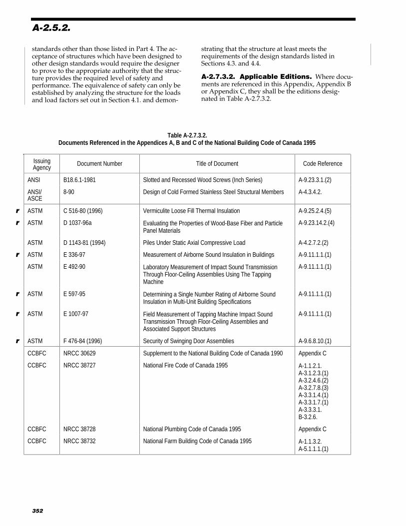
A-2.5.2.
352
standards other than those listed in Part 4. The ac-ceptance of structures which have been designed toother design standards would require the designerto prove to the appropriate authority that the struc-ture provides the required level of safety andperformance. The equivalence of safety can only beestablished by analyzing the structure for the loadsand load factors set out in Section 4.1. and demon-
strating that the structure at least meets therequirements of the design standards listed inSections 4.3. and 4.4.
A-2.7.3.2. Applicable Editions. Where docu-ments are referenced in this Appendix, Appendix Bor Appendix C, they shall be the editions desig-nated in Table A-2.7.3.2.
Table A-2.7.3.2.Documents Referenced in the Appendices A, B and C of the National Building Code of Canada 1995
IssuingAgency
Document Number Title of Document Code Reference
ANSI B18.6.1-1981 Slotted and Recessed Wood Screws (Inch Series) A-9.23.3.1.(2)
ANSI/ASCE
8-90 Design of Cold Formed Stainless Steel Structural Members A-4.3.4.2.
r ASTM C 516-80 (1996) Vermiculite Loose Fill Thermal Insulation A-9.25.2.4.(5)
r ASTM D 1037-96a Evaluating the Properties of Wood-Base Fiber and ParticlePanel Materials
A-9.23.14.2.(4)
ASTM D 1143-81 (1994) Piles Under Static Axial Compressive Load A-4.2.7.2.(2)
r ASTM E 336-97 Measurement of Airborne Sound Insulation in Buildings A-9.11.1.1.(1)
ASTM E 492-90 Laboratory Measurement of Impact Sound TransmissionThrough Floor-Ceiling Assemblies Using The TappingMachine
A-9.11.1.1.(1)
r ASTM E 597-95 Determining a Single Number Rating of Airborne SoundInsulation in Multi-Unit Building Specifications
A-9.11.1.1.(1)
r ASTM E 1007-97 Field Measurement of Tapping Machine Impact SoundTransmission Through Floor-Ceiling Assemblies andAssociated Support Structures
A-9.11.1.1.(1)
r ASTM F 476-84 (1996) Security of Swinging Door Assemblies A-9.6.8.10.(1)
CCBFC NRCC 30629 Supplement to the National Building Code of Canada 1990 Appendix C
CCBFC NRCC 38727 National Fire Code of Canada 1995 A-1.1.2.1.A-3.1.2.3.(1)A-3.2.4.6.(2)A-3.2.7.8.(3)A-3.3.1.4.(1)A-3.3.1.7.(1)A-3.3.3.1.B-3.2.6.
CCBFC NRCC 38728 National Plumbing Code of Canada 1995 Appendix C
CCBFC NRCC 38732 National Farm Building Code of Canada 1995 A-1.1.3.2.A-5.1.1.1.(1)

A-2.7.3.2.
353
Table A-2.7.3.2. (Continued)
IssuingAgency
Document Number Title of Document Code Reference
e CCBFC NRCC 38826 Structural Commentaries on the National BuildingCode of Canada 1995
A-1.1.2.1.A-4.1.1.3.(1)A-4.1.1.5.(1)A-4.1.1.5.(4)A-4.1.1.6.(1)A-4.1.1.6.(2)A-4.1.2.1.(1)A-4.1.3.A-4.1.4.3.A-4.1.6.9.A-4.1.7.A-4.1.7.1.A-4.1.7.2.(2)A-4.1.7.3.(1)A-4.1.8.1.(1), (2)A-4.1.8.1.(5)(c)A-4.1.8.1.(6)(a)A-4.1.8.1.(6)(d) andA-4.1.8.2.(1)(b)A-4.1.8.3.(1)A-4.1.9.1.(2)A-4.1.9.1.(3)A-4.1.9.1.(8) andA-Table 4.1.9.1.B.A-4.1.9.1.(13)(b)A-Table 4.1.9.1.D.A-Table 4.1.9.1.E.A-4.1.9.1.(28)A-4.1.9.1.(29)A-4.1.9.4.(5)A-4.1.10.4.A-4.1.10.6.(1)A-4.2.4.4.A-4.2.4.5.A-4.2.5.1.A-4.2.6.1.A-4.2.7.2.(1)A-5.1.4.2.Appendix C
r CGA CAN/CGA-B149.1-M95 Natural Gas Installation Code A-9.10.21.
CGSB CAN/CGSB-12.20-M89 Structural Design of Glass for Buildings A-9.7.3.2.(1)
e CGSB 37-GP-52M-1984 Roofing and Waterproofing Membrane, Sheet Applied,Elastomeric
A-5.8.2.2.(6)
CGSB 37-GP-56M-1985 Membrane, Modified, Bituminous, Prefabricated, andReinforced for Roofing
A-5.6.1.2. (1) and (3)
r CGSB CAN/CGSB-51.34-M86(Amended 1988)
Vapour Barrier, Polyethylene Sheet for Use in BuildingConstruction
A-5.5.1.2.(2)
CGSB CAN/CGSB-71.26-M88 Adhesive for Field-Gluing Plywood to Lumber Framing forFloor Systems
Table A-9.23.4.2.C.
CGSB CAN/CGSB-82.6-M86 Doors, Mirrored Glass, Sliding or Folding, Wardrobe A-9.6.6.3.(1)
CMHC Testing of Fresh Air Mixing Devices A-9.32.3.6.
CMHC Air Permeance of Building Materials A-5.4.1.2.(1) and (2)
CSA A23.3-94 Design of Concrete Structures A-4.3.3.1.
CSA A23.4-94 Precast Concrete Materials and Construction A-4.3.3.1.

A-2.7.3.2.
354
Table A-2.7.3.2. (Continued)
IssuingAgency
Document Number Title of Document Code Reference
CSA CAN/CSA-A82.1-M87 Burned Clay Brick (Solid Masonry Units Made from Clay orShale)
A-5.6.1.2. (1) and (3)
CSA A82.31-M80 Gypsum Board Application Table A-9.10.3.1.A.Table A-9.10.3.1.B.
CSA CAN/CSA-A277-90 Certification of Factory-Built Houses A-2.1.4.1.(1)
CSA A370-94 Connectors for Masonry A-9.21.4.5.(2)
CSA A371-94 Masonry Construction for Buildings A-5.6.1.2. (1) and (3)
CSA CAN/CSA-A440-M90 Windows A-5.4.1.2.(3)A-9.7.2.1.(1)
CSA A440.1-M1990 User Selection Guide to CAN/CSA-A440-M90 Windows A-9.7.2.1.(1)
r CSA CAN/CSA-B44-M94(Supplement 1− B44S1-97)
Safety Code for Elevators A-3.5.2.1.(1)
CSA CAN/CSA-B365-M91 Installation Code for Solid-Fuel-Burning Appliances andEquipment
A-9.33.1.1.(2)
CSA C22.1-94 Canadian Electrical Code, Part 1 A-3.1.4.3.(1)(b)(i)
CSA CAN/CSA-F326-M91 Residential Mechanical Ventilation Systems A-9.32.3.A-9.33.6.14.
CSA O86.1-94 Engineering Design in Wood (Limit States Design) A-9.15.1.3.(3)A-9.23.4.2.
CSA CAN/CSA-O141-91 Softwood Lumber A-9.3.2.1.(1)
CSA O437.0-93 OSB and Waferboard A-9.23.14.4.(2)
e CSA CAN/CSA-S6-88 Design of Highway Bridges A-Table 4.1.6.10.
CSA CAN/CSA-S16.1-94 Limit States Design of Steel Structures A-4.3.4.1.
CSA CAN/CSA-S406-92 Construction of Preserved Wood Foundations A-9.15.1.3.(3)
CSA CAN/CSA Z32.4-M86 Essential Electrical Systems for Hospitals A-3.2.7.6.(1)
e CSA CAN/CSA-Z240MH Series-92
Mobile Homes A-2.1.4.1.(1)
CWC The Span Book (Second Revision, 1993) A-9.23.4.2.
FCC Project 03-50-10-008 Serviceability Criteria for Residential Floors Based on a FieldStudy of Consumer Response (1985)
A-9.23.4.2.(2)
FMEC FM 2008 Early Suppression-Fast Response Sprinklers A-3.2.5.13.(7)
FPS Performance Criteria for Residential Floors Based onConsumer Responses (1988)
A-9.23.4.2.(2)
HC H49-58 Exposure Guidelines for Residential Indoor Air Quality A-9.13.8.2.
IRC BPN 61 Shear Resistance of Wood Frame Walls A-9.23.10.2.
IRC CBD 222 Airtight Houses and Carbon Monoxide Poisoning A-9.33.1.1.(2)
IRC CBD 230 Applying Building Codes to Existing Buildings A-1.1.2.1.
IRC CBD 231 Moisture Problems in Houses A-9.25.3.1.(1)

A-2.7.3.2.
355
Table A-2.7.3.2. (Continued)
IssuingAgency
Document Number Title of Document Code Reference
IRC NRCC 28822 Performance and Acceptability of Wood Floors − ForintekStudies
A-9.23.4.2.(2)
ISO 7731:1986 Danger signals for workplaces − Auditory danger signals A-3.2.4.22.(1)(b)
ISO 8201:1987 Acoustics − Audible emergency evacuation signal A-3.2.4.19.(2)
r NFPA 13-1996 Installation of Sprinkler Systems A-3.2.4.9.(2)(f)A-3.2.5.13.(1)A-3.2.5.13.(6)A-3.2.5.13.(7)A-3.2.5.14.(1)A-3.2.8.2.(3)
r NFPA 13D-1996 Installation of Sprinkler Systems in One- and Two-FamilyDwellings and Manufactured Homes
A-3.2.5.13.(7)A-3.2.5.14.(1)
r NFPA 13R-1996 Installation of Sprinkler Systems in Residential Occupanciesup to and including Four Stories in Height
A-3.2.5.13.(7)A-3.2.5.14.(1)
r NFPA 20-1996 Installation of Centrifugal Fire Pumps A-3.2.4.9.(2)(f)A-3.2.5.19.(1)
r NFPA 30-1996 Flammable and Combustible Liquids Code A-6.2.2.5.
r NFPA 32-1996 Drycleaning Plants A-6.2.2.5.
r NFPA 33-1995 Spray Application Using Flammable or Combustible Materials A-6.2.2.5.
r NFPA 34-1995 Dipping and Coating Processes Using Flammable orCombustible Liquids
A-6.2.2.5.
r NFPA 35-1995 Manufacture of Organic Coatings A-6.2.2.5.
r NFPA 36-1997 Solvent Extraction Plants A-6.2.2.5.
r NFPA 40-1997 Storage and Handling of Cellulose Nitrate Motion Picture Film A-6.2.2.5.
NFPA 50A-1994 Gaseous Hydrogen Systems at Consumer Sites A-6.2.2.5.
NFPA 50B-1994 Liquefied Hydrogen Systems at Consumer Sites A-6.2.2.5.
r NFPA 51-1997 Design and Installation of Oxygen-Fuel Gas Systems forWelding, Cutting, and Allied Processes
A-6.2.2.5.
r NFPA 51A -1996 Acetylene Cylinder Charging Plants A-6.2.2.5.
r NFPA 61-1995 Prevention of Fires and Dust Explosions in Agricultural andFood Products Facilities
A-6.2.2.5.
NFPA 65-1993 Processing and Finishing of Aluminum A-6.2.2.5.
r NFPA 68-1994 Venting of Deflagrations A-6.2.2.5.
r NFPA 69-1997 Explosion Prevention Systems A-6.2.2.5.

A-2.7.3.2.
356
Table A-2.7.3.2. (Continued)
IssuingAgency
Document Number Title of Document Code Reference
r NFPA 80-1995 Fire Doors and Fire Windows A-3.1.8.1.(2)A-3.2.8.2.(3)
r NFPA 80A-1996 Protection of Buildings from Exterior Fire Exposures A-3
NFPA 81-1986 Fur Storage, Fumigation and Cleaning A-6.2.2.5.
r NFPA 86-1995 Ovens and Furnaces A-6.2.2.5.
r NFPA 88A -1995 Parking Structures A-6.2.2.5.
r NFPA 88B-1997 Repair Garages A-6.2.2.5.
r NFPA 91-1995 Exhaust Systems for Air Conveying of Materials A-6.2.2.5.
e NFPA 96-1994 Ventilation Control and Fire Protection of Commercial CookingOperations
A-3.3.1.2.(2)A-6.2.2.5.A-9.10.1.4.(1)
NFPA 204M-1991 Guide for Smoke and Heat Venting A-6.2.2.5.
r NFPA 303-1995 Marinas and Boatyards A-6.2.2.5.
r NFPA 307-1995 Construction and Fire Protection of Marine Terminals, Piersand Wharfs
A-6.2.2.5.
r NFPA 325-1994 Fire Hazard Properties of Flammable Liquids, Gases andVolatile Solids
A-6.2.2.5.
e NFPA 326-1993 Safe Entry of Underground Storage Tanks A-8.2.2.12.(3)
NFPA 327-1993 Cleaning or Safeguarding Small Tanks and ContainersWithout Entry
A-8.2.2.12.(3)
NFPA 395-1993 Storage of Flammable and Combustible Liquids at Farms andIsolated Sites
A-6.2.2.5.
r NFPA 409-1995 Aircraft Hangars A-6.2.2.5.
r NFPA 415-1997 Airport Terminal Buildings, Fueling, Ramp Drainage, LoadingWalkways
A-6.2.2.5.
NFPA 480-1993 Storage, Handling and Processing of Magnesium Solids andPowders
A-6.2.2.5.
r NFPA 481-1995 Production, Processing, Handling and Storage of Titanium A-6.2.2.5.
r NFPA 482-1996 Production, Processing, Handling and Storage of Zirconium A-6.2.2.5.
NFPA 490-1993 Storage of Ammonium Nitrate A-6.2.2.5.
NFPA 650-1990 Pneumatic Conveying Systems for Handling CombustibleMaterials
A-6.2.2.5.
NFPA 651-1993 Manufacture of Aluminum Powder A-6.2.2.5.
r NFPA 654-1997 Prevention of Fire and Dust Explosions from theManufacturing, Processing, and Handling of CombustibleParticulate Solids
A-6.2.2.5.
NFPA 655-1993 Prevention of Sulfur Fires and Explosions A-6.2.2.5.
NFPA 664-1993 Prevention of Fires and Explosions in Wood Processing andWoodworking Facilities
A-6.2.2.5.
r NFPA 8503-97 Pulverized Fuel Systems A-6.2.2.5.

A-3
357
Table A-2.7.3.2. (Continued)
IssuingAgency
Document Number Title of Document Code Reference
NLGA 1994 Standard Grading Rules for Canadian Lumber A-9.3.2.1.(1)Table A-9.3.2.1.A.A-9.3.2.8.(1)A-9.23.10.4.(1)
NLGA SPS-1 Fingerjoined Structural Lumber A-9.23.10.4.(1)
NLGA SPS-3 Fingerjoined Stud − Vertical Use Only A-9.23.10.4.(1)
ONHWP Details of Air Barrier Systems for Houses Table A-9.25.1.2.B.
UL UL 199 (1990) Automatic Sprinklers for Fire-Protection Service A-3.2.5.13.(7)
UL UL 1626 (1994) Residential Sprinklers for Fire-Protection Service A-3.2.5.13.(7)
ULC CAN/ULC-S101-M89 Fire Endurance Tests of Building Construction and Materials A-3.1.5.11.(2)(e)B-3.2.6.5.(6)(b)
ULC CAN/ULC-S112-M90 Fire Test of Fire Damper Assemblies Table B-3.2.6.6.C.
ULC CAN4-S113-79 Wood Core Doors Meeting the Performance Required byCAN4-S104-77 for Twenty Minute Fire Rated ClosureAssemblies
A-9.10.13.2.(1)
ULC CAN4-S114-M80 Test for the Determination of Non-Combustibility in BuildingMaterials
A-3.1.5.2.(1)(b)
ULC CAN4-S124-M85 Test for the Evaluation of Protective Coverings for FoamedPlastic
A-3.1.5.11.(2)(e)
r ULC ULC-S332-93 Burglary Resisting Glazing Material A-9.6.8.1.
ULC CAN/ULC-S526-M87 Visual Signal Appliances for Fire Alarm Systems A-3.2.4.20.(1)
r ULC CAN/ULC-S702-97 Thermal Insulation, Mineral Fibre, for Buildings A-5.3.1.2.(2)
e WCLIB No. 17 (1993) Standard Grading Rules A-Table 9.3.2.1.
e WWPA 1995 Western Lumber Grading Rules A-Table 9.3.2.1.
A-3 Application of Part 3. In applying the re-quirements of this Part, it is intended that they beapplied with discretion to buildings of unusual con-figuration that do not clearly conform to the specificrequirements, or to buildings in which processes arecarried out which make compliance with particularrequirements in this Part impracticable. The defini-tion of “building” as it applies to this Code isgeneral and encompasses most structures, includingthose which would not normally be considered asbuildings in the layman's sense. This occurs moreoften in industrial uses, particularly those involvingmanufacturing facilities and equipment that requirespecialized design that may make it impracticable tofollow the specific requirements of this Part. Steelmills, aluminum plants, refining, power generationand liquid storage facilities are examples. A watertank or an oil refinery, for example, has no floorarea, so it is obvious that requirements for exitsfrom floor areas would not apply. Requirements forstructural fire protection in large steel mills andpulp and paper mills, particularly in certain por-
tions, may not be practicable to achieve in terms ofthe construction normally used and the operationsfor which the space is to be used. In other portionsof the same building, however, it may be quite rea-sonable to require that the provisions of this Part beapplied (e.g., the office portions). Similarly, areas ofindustrial occupancy which may be occupied onlyperiodically by service staff, such as equipmentpenthouses, normally would not need to have thesame type of exit facility as floor areas occupied ona continuing basis. It is expected that judgment willbe exercised in evaluating the application of arequirement in those cases when extenuating cir-cumstances require special consideration, providedthe occupants’ safety is not endangered.
The provisions in this Part for fire protection fea-tures installed in buildings are intended to provide aminimum acceptable level of public safety. It is in-tended that all fire protection features of a building,whether required or not, will be designed in confor-mance with good fire protection engineering

A-3
practice and will meet the appropriate installationrequirements in relevant standards. Good design isnecessary to ensure that the level of public safetyestablished by the Code requirements will not be re-duced by a voluntary installation.
Fire Fighting Assumptions
The requirements of this Part are based on the as-sumption that fire fighting capabilities are availablein the event of a fire emergency. These fire fightingcapabilities may take the form of a paid or volun-teer public fire department or in some cases aprivate fire brigade. If these fire fighting capabilitiesare not available, additional fire safety measuresmay be required.
Fire fighting capability can vary from municipalityto municipality. Generally, larger municipalitieshave greater fire fighting capability than smallerones. Similarly, older, well established municipali-ties may have better fire fighting facilities thannewly formed or rapidly growing ones. The level ofmunicipal fire protection considered to be adequatewill normally depend on both the size of the munic-ipality (i.e., the number of buildings to be protected)and the size of buildings within that municipality.Since larger buildings tend to be located in largermunicipalities, they are generally, but not always,favoured with a higher level of municipal protec-tion.
Although it is reasonable to consider that somelevel of municipal fire fighting capability was as-sumed in developing the fire safety provisions inPart 3, this was not done on a consistent or definedbasis. The requirements in the Code, while devel-oped in the light of commonly prevailing municipalfire protection levels, do not attempt to relate thesize of building to the level of municipal protection.The responsibility for controlling the maximum sizeof building to be permitted in a municipality in re-lation to local fire fighting capability rests with themunicipality. If a proposed building is too large,either in terms of floor area or building height, to re-ceive reasonable protection from the municipal firedepartment, fire protection requirements in additionto those prescribed in this Code, may be necessaryto compensate for this deficiency. Automatic sprin-kler protection may be one option to be considered.
Alternatively, the municipality may, in light of itsfire fighting capability, elect to introduce zoning re-strictions to ensure that the maximum building sizeis related to available municipal fire protection facil-ities. This is, by necessity, a somewhat arbitrarydecision and should be made in consultation withthe local fire fighting service, who should have anappreciation of their capability to fight fires.
The requirements of Subsection 3.2.3. are intendedto prevent fire spread from thermal radiation as-suming there is adequate fire fighting available. Ithas been found that periods of from 10 to 30 min-utes usually elapse between the outbreak of fire in abuilding that is not protected with an automaticsprinkler system and the attainment of high radia-tion levels. During this period, the specified spatialseparations should prove adequate to inhibit igni-tion of an exposed building face or the interior of anadjacent building by radiation. Subsequently, how-ever, reduction of the fire intensity by fire fightingand the protective wetting of the exposed buildingface will often be necessary as supplementary mea-sures to inhibit fire spread.
In the case of a building that is sprinklered through-out, the automatic sprinkler system should controlthe fire to an extent that radiation to neighbouringbuildings should be minimal. Although there willbe some radiation effect on a sprinklered buildingfrom a fire in a neighbouring building, the internalsprinkler system should control any fires that mightbe ignited in the building and thereby minimize thepossibility of the fire spreading into the exposedbuilding. NFPA 80A, “Protection of Buildingsfrom Exterior Fire Exposures,” providesadditional information on the possibilityof fire spread at building exteriors.
The water supply requirements for fire protectioninstallations depend on the requirements of any au-tomatic sprinkler installations and also on thenumber of fire streams that may be needed at anyfire, having regard to the length of time the streamswill have to be used. Both these factors are largelyinfluenced by the conditions at the building to beequipped, and the quantity and pressure of waterneeded for the protection of both the interior andexterior of the building must be ascertained beforethe water supply is decided upon. Acceptable watersupplies may be a public waterworks system thathas adequate pressure and discharge capacity, auto-matic fire pumps, pressure tanks, manuallycontrolled fire pumps in combination with pressuretanks, gravity tanks, and manually controlled firepumps operated by remote control devices at eachhose station.
A-3.1.2. Use Classification. The purpose ofclassification is to determine which requirementsapply. This Code requires classification in accor-dance with every major occupancy for which thebuilding is used or intended to be used. Where nec-essary, an application clause has been inserted inthis Part to explain how to choose between the al-ternative requirements which multiple occupancyclassification may present.
A-3.1.2.1.(1) Major OccupancyClassification. The following are examples of the
358

A-3.2.4.19.
annunciator, the signals must be routed to the an-nunciator through the control unit and the samefunctionality must be available at the control unitfor operation and maintenance functions.
A-3.2.4.9.(2)(f) Supervision for FirePumps. Specific electrical supervision for firepumps is stated in NFPA 20, “Installationof Centrifugal Fire Pumps,” which isreferenced in NFPA 13, “Installationof Sprinkler Systems.”
A-3.2.4.11. Smoke Detector Location. Inthe design and installation of the smoke detectionsystem, consideration must be given to all featureswhich could have a bearing on the location and sen-sitivity of the detectors, including ceiling height,sloped ceilings, diffusion from air conditioning andventilating currents, obstructions, baffles, and otherpertinent physical configurations that might inter-fere with the proper operation of the system.
A-3.2.4.17.(1) Manual Pull Station. Only onemanual pull station need be provided near a groupof doors serving as a principal entrance or as a sin-gle exit facility.
A-3.2.4.19. Acoustic Measurement andTerminology. The following notes on acousticmeasurement and terminology are intended toassist in the application of the requirements for au-dibility of fire alarm system sounding devices.
The background or ambient measurement should bea spatial averaged A-weighted equivalent soundlevel measured for 60 s. This can be obtained usingan integrating sound level meter with the integra-tion time set to 60 s. During the measurementperiod the meter should be slowly moved about soas to sample the space uniformly but coming nocloser than 0.5 m from any solid wall, floor or ceil-ing. Alternatively, measurements can be made at 3or more positions throughout the space and an en-ergy average calculated.
The measurement of the alarm level depends on thetype of alarm signal. If the signal is a continuoussignal from a bell or siren, the spatial averagedA-weighted equivalent sound level should be ob-tained. The integration time should be long enoughto obtain a reasonable spatial average of the space,but not less than 10 s.
If the alarm has a temporal pattern, then the A-weighted sound level should be measured using the‘fast’ time constant during the ‘on’ part of the cycle.In this situation it is not appropriate to use an inte-grating sound level meter. Since the duty cycle ofthe alarm is only 37.5% at best, that type of meterwould give a reading that is 4 or more decibelslower than the level while the alarm is ‘on.’ A num-
ber of measurements should be made about thespace in question and the average value used to ob-tain a good spatial representation. Strictly speaking,the energy average of the measurements should beused; however, the frequency spectrum associatedwith most alarms is of a type that should give littlevariation about the space. If the measured levelsdon’t vary by more than 2 to 3 dB, then an arith-metic average rather than an energy average can beused.
Effect of Furnishings
The final inspection of a fire alarm system is seldommade when the building is furnished and ready foroccupancy. This results in measured levels whichmay be several decibels higher than will be foundin the occupied building. The importance of this dif-ference depends on the situation.
If the building is complete except for furnishings, sothat the sources of ambient noise are present, thenthe amount by which the alarm signal exceeds theambient level will not change appreciably with theintroduction of furnishings. In this case both levelswill be reduced by about the same amount.
If the primary source of ambient noise will be officeequipment and workers, as would be expected in anopen plan office, then measurements made prior tooccupancy may differ substantially from thosemade afterwards. This may be true for both the ab-solute sound levels and the difference between thealarm level and the ambient.
A problem arises in trying to estimate what the ab-solute sound levels will be after the building isoccupied.
In general, if the measurement is made in a totallybare room then the level will be about 3 dB higherthan if the room were carpeted, assuming a reason-able carpet with an underlay. In most cases this willaccount for most of the absorption in the room andno further correction will be necessary. Addingheavy drapes and absorptive furnishings to a car-peted room can reduce the sound level by a further2 to 3 dB.
Commercial buildings are more problematic. For ex-ample, if an open plan office is measured before anyoffice screens are installed, there could be a substan-tial difference in the before and after levels,depending on the distance to the nearest alarm de-vice.
Glossary of Acoustical Terms
Audible: A signal is usually considered to be clearlyaudible if the A-weighted sound level exceeds thelevel of ambient noise by 15 dB or more.
365

A-3.2.4.19.
366
Awakening threshold: The level of sound that willawaken a sleeping subject 50% of the time.
A-weighted: A frequency weighting network whichemphasizes the middle frequency componentssimilar to the response of the human ear. The A-weighted sound level correlates well with subjectiveassessment of the disturbing effects of sounds. Thequantity is expressed in dBA.
Masked threshold: The level of sound at which asignal is just audible in ambient noise.
Sound level: A sound pressure level obtained usinga signal to which a standard frequency-weightinghas been applied.
Sound pressure: A fluctuating pressure superim-posed on the static pressure by the presence ofsound. The unqualified term means the root-mean-square sound pressure. In air, the static pressure isbarometric pressure.
Sound pressure level: Ten times the common loga-rithm of the ratio of the square of the soundpressure under consideration to the square of thestandard reference pressure of 20 mPa. The quantityobtained is expressed in decibels.
A-3.2.4.19.(1) Alert and Alarm Signals.Alert signals are part of a 2 stage fire alarm system.The intent of the first, alert, stage is to notify personsin authority of a potential threat to building occu-pants. If a continuously staffed location is available,the alert signal can be restricted to that location.
A-3.2.4.19.(2) Alarm Signal TemporalPattern. The temporal pattern of an alarm signalrelates to the time during which the signal is pro-duced and the intervals between the individualsignal pulses. The international standard ISO 8201,“Acoustics – Audible emergency evacuation signal,”includes a pattern that is becoming widely used indifferent countries and it is appropriate for this pat-tern to be adopted in Canada. The temporal patterncan be produced on most signalling devices. Mostexisting alarm systems can be modified, and thispattern could be phased in when the systems re-quire modification. The characteristic of the patternis a 3-pulse phase followed by an off phase. The 3pulses each consist of an on phase lasting for0.5 ± 0.05 s followed by an off phase lasting for0.5 ± 0.05 s sounded for 3 successive on periods andthen followed by an off phase lasting for1.5 ± 0.15 s. Figure A-3.2.4.19.(2).A. indicates thepattern that is intended.
On
Off
One cycle
a b a b a c a
Phase a: signal is on for 0.5 ± 0.05 sPhase b: signal is off for 0.5 ± 0.05 sPhase c: signal is off for 1.5 ± 0.15 sTotal cycle to last 4.0 ± 0.40 s
Figure A-3.2.4.19.(2).A.Temporal pattern for fire alarm signal
Although the diagram shows a square wave form,the wave can have other shapes that produce a sim-ilar effect.
If single stroke bells are to be used, the temporalpattern can be produced by having the bell struckthree times at a rate of one stroke per secondfollowed by an interval of 2 s of silence. Figure A-3.2.4.19.(2).B. shows the pattern that results.
On
Off
0 2 4 6 8 10 Time, s
Figure A-3.2.4.19.(2).B.
Temporal pattern imposed on a single stroke bell or chimeNote to Figure A-3.2.4.19.(2).B. The on phase represents the time thatthe striker mechanism is actuated. The sound produced by the bell orchime will continue at a level that decreases until the striker mechanismis re-actuated.
A-3.2.4.19.(4) Sound Pressure Level. For thepurposes of this requirement, an audible signalling de-vice should not produce a sound pressure level morethan 110 dBA when measured at a distance of 3 m.
A-3.2.4.19.(5) Residential Sound Level. In abuilding in which corridors or hallways serve morethan one suite or dwelling unit, there will besituations in which an audible signal device cannotbe placed in the corridor or hallway to alert personssleeping in suites and dwelling units, because thesound level in the vicinity of the device would ex-ceed that permitted by Sentence 3.2.4.19.(4). In thesesituations it will be necessary to supplement thebuilding fire alarm system with an audible signaldevice in the suite or dwelling unit. These devicescould be piezoelectric devices similar to the sound-ing units in many smoke alarms, subject to thedevice emitting the appropriate temporal pattern re-quired by Sentence 3.2.4.19.(2).
A-3.2.4.19.(9) Disconnect Device forDwelling Units. In order to minimize the annoy-ance caused by false and unwanted alarms, the
e

A-3.8.3.7.
seconds before it begins to close might be desirable.However, closers with this feature have limitedback-check, a feature of a normal door closer whereresistance to opening increases as the door reachesthe full arc of swing. Doors equipped with a de-layed action closer are therefore more susceptible todamage should the door be opened with too muchforce or should someone try to force it closed, think-ing the closer has failed to operate. Delayed actionclosers are not recommended for such occupanciesas schools.
A-3.8.3.3.(10) Clearances at Doorways.Sufficient clearance must be provided on the latchside of doors for a user to operate the door openingmechanism and open the door without interferencefrom the wheelchair. This is particularly importantwhere the door swings towards the approach side.Although the requirement applies only to doors
e equipped with closers, this clearance should beprovided for all doors.
600 mm 300 mm
Figure A-3.8.3.3.(10)
Doorway clearance
A-3.8.3.4.(1)(b) Ramp Slopes. Ramps with aslope of more than 1 in 16 can be very difficult forpersons with physical disabilities with upper bodymobility to manage. Even though they pose less of aproblem for persons in motorized wheelchairs, theseramps can be unsafe to descend, especially in coldclimates. Although Article 3.8.3.4. permits slopes onramps as great as 1 in 12 for distances of up to 9 m,slopes of 1 in 20 are safer and less strenuous. Whenlimited space is available, as may be the case duringrenovations, ramps with a slope of up to 1 in 12should be restricted to lengths not exceeding 3 mwhenever possible. A strip contrasting in colour andtexture should be used at the top and bottom oframps to warn blind and visually impaired persons.
A-3.8.3.4.(1)(c) Landing Design atDoorways Leading to Ramps
1500
mm
min
.
1500 mm min.
600 mmmin.
ramp 1500
mm
min
.
1500 mm min.
300 mmmin.
ramp
Figure A-3.8.3.4.(1)(c)
Landing design at doorways leading to ramps
A-3.8.3.7. Assistive Listening Systems.Wireless sound transmission systems, including FM,infrared or magnetic induction loop systems, im-prove sound reception for persons with hearingdisabilities by providing amplification which can beadjusted by each user while blocking out unwantedbackground noise. These systems transmit a signalthat is picked up by a special receiver available foruse by a person with a hearing disability, whetheror not a hearing aid is used. Neither system inter-feres with the listening enjoyment of others.
The transmitter can be jacked into an existing P.A.system amplifier or used independently with micro-phones. The induction loop system requires users tosit in the area circumscribed by the loop; though in-stallation of the loop is relatively simple, theinstaller should be knowledgeable about these sys-tems if proper functioning is to be achieved. FM orinfrared systems can be designed to broadcast sig-nals which cover the entire room and thus do notrestrict seating to any one area. Figures A-3.8.3.7.A.and A-3.8.3.7.B. show the general configuration ofFM and infrared systems. Although portable sys-tems (FM in particular) are available, these are bestsuited to small audiences. Generally, the systems in-stalled in church halls, auditoria, theatres andsimilar places of assembly are not easily portable, asthey are installed in a fixed location by a soundtechnician and form an integral part of the P.A. sys-tem of the room or building.
Hard-wired systems (where a jack is provided at aparticular seat) will not meet this requirement un-less adequate provisions are made to accommodatepersons with hearing aids. In choosing the most ap-propriate system, a number of factors must be takeninto account including cost, installation and mainte-nance, suitability to the audience, ease of operationand the need for privacy. Information on designersand suppliers of these systems may be obtainedfrom the Canadian Hearing Society.
379

A-3.8.3.8.(1)(b)(iii)
Microphone, Tape, T.V., Film, etc.
Speakers
FM Transmitter
FM Receiver
Nor
mal
Sou
ndS
yste
mF
M B
road
cast
Sys
tem
Amplifier
02
Figure A-3.8.3.7.A.
FM sound transmission system
Microphone, Tape, T.V., Film, etc.
Amplifier
Speakers
InfraredControlTransmitter
Nor
mal
Sou
ndS
yste
mIn
frar
edS
yste
m
Infrared Light Waves
Infrared Receiver
Infrared Radiator (One or more)
02
Figure A-3.8.3.7.B.
Infrared sound transmission system
A-3.8.3.8.(1)(b)(iii) Water Closet Stalls.Doors to water closet stalls for persons with physi-cal disabilites should swing outward, preferablyagainst a side wall.
stall stall stall
wall mountedfixture
door to washroom
1.7
m
1.4
m
Figure A-3.8.3.8.(1)(b)(iii)
Water closet stalls
A-3.8.3.8.(1)(b)(iv) Door Pulls. The door pullshould consist of a D-shaped handle mounted eitherhorizontally or vertically. The centerlines are thelines drawn through the long axis and the short axisof the handle. If the handle is installed in the hori-zontal position, the short or transverse axis is thecenterline which must be located at between200 and 300 mm from the hinged side of the door,and the long or longitudinal axis is the one which islocated between 900 and 1 000 mm from the floor. Ifthe handle is installed in the vertical position, thedistance is measured from the longitudinal axis tothe hinged side of the door, while the distance fromthe floor is measured to the transverse axis.
300 mm
900
mm
1 00
0 m
m
Extent of area wheremidpoint must be located
200 mm
Figure A-3.8.3.8.(1)(b)(iv).A.
Door pull location
380

A-5.4.1.2.(1) and (2)
building to the night sky and the time lag in tem-perature change due to the thermal mass of thebuilding and its contents. If this temperature differ-ence is not “intended,” no special considerationneed be given to the control of heat flow.
If the warehouse is heated or cooled, thus makingthe temperature difference “intended,” some consid-eration would have to be given to the control ofheat flow.
It should be noted, however, that in many cases,such as with adjacent interior spaces, there will bean intended temperature difference but the differ-ence will not be great. In these cases, the provisionsto control heat flow may be little or no more thanwould be provided by any standard interior separa-tor. That is, materials typically used in theconstruction of partitions may provide the separa-tion needed to meet the requirements of Section 5.3.without adding what are generally considered to be“insulating” materials.
A-5.3.1.2. Material and ComponentProperties and Condensation. Total preven-tion of condensation is generally unnecessary andits achievement is rarely a certainty at design condi-tions. Part 5, therefore, requires that condensationbe minimized. The occurrence of condensationshould be sufficiently rare, or the quantities accu-mulated should be sufficiently small and dryrapidly enough, to avoid material deterioration andthe growth of mould and fungi.
A-5.3.1.2.(2) Materials ProvidingResistance to Heat Transfer. It is importantto note that Sentence 5.3.1.2.(2), pertaining to mate-rials intended to provide resistance to heat transfer,is stated in such a fashion that the selection of mate-rials is not limited to those traditionally recognizedas insulation materials or those for which a stan-dard is identified. This approach permits moreflexibility than is provided by the equivalentrequirements in Part 9. So long as the selected mate-rial meets the performance requirements providedelsewhere in the Section, the material may be usedto provide the necessary resistance to heat transfer.
Where the selected material falls within the scope ofany of the standards that have been listed, however,the material must also comply with that standard.For example, if some resistance to heat transfer isrequired between two interior spaces and standardpartition construction will provide the necessaryresistance, the installation of one of the “thermal in-sulation” materials identified in the standard list isnot required. If, on the other hand, one decides toinstall glass fibre insulation, the material must con-
r form to CAN/ULC-S702.
A-5.3.1.2.(5) Heat Transfer through Firer Rated Glazed Assemblies. Thermal bridging
through fire rated glazed assemblies should notbe ignored; measures should be taken to minimizecondensation consistent with the intent of Sentence5.3.1.2.(4).
A-5.3.1.3.(2) Position of MaterialsProviding Thermal Resistance. For a materialproviding thermal resistance to be effective, it mustnot be short-circuited by convective air flowthrough or around the material. The material musttherefore be either
• the component of the air barrier system pro-viding principal resistance to air leakage, or
• installed in full and continuous contact with acontinuous low air permeance component.
A-5.4.1.1. Resistance to Air Leakage. Theair barrier system in above grade building compo-nents and assemblies separating conditioned spacefrom the exterior will reduce the likelihood of con-densation due to air leakage, discomfort fromdrafts, infiltration of dust and other pollutants, andinterference in the performance of building servicessuch as HVAC and plumbing. These can all lead toserious health or safety hazards.
Currently, the most obvious and significantproblems are due to moisture-related material dete-rioration such as rot and corrosion, which can leadto failure of component connections. Infiltration ofdust and other pollutants can lead to a wide rangeof health problems. Where the separator is subjectto high moisture levels, the pollutants may includefungus spores. Interference with the performance ofbuilding services can lead to unhealthy conditions,and potentially hazardous conditions during theheating season in many regions of the country.
Where adjacent interior environments are suffi-ciently different, control of air flow between thosespaces is necessary to maintain conditions.
An air barrier system may be required in compo-nents and assemblies in contact with the ground tocontrol the transfer of soil gases such as radon andmethane.
A-5.4.1.2.(1) and (2) Air Leakage throughthe Air Barrier System
Material Requirements
The current requirements specify only a maximumair leakage rate for the material in the air barriersystem that provides the principal resistance to airleakage.
The report, “Air Permeance of Building Materials,”prepared by AIR-INS Inc. for CMHC (1988) identi-fies, from 36 common building materials, 19 whichwould comply with the leakage limit of
387

A-5.4.1.2.(1) and (2)
0.02 L/(s • m2) at 75 Pa. Air leakage characteristicsgreater than the maximum of 0.02 L/(s • m2) at75 Pa may be acceptable where
• exterior temperatures are mild,• the moisture content of the indoor air is low,• the assembly is resistant to moisture-related
deterioration,• higher vapour permeance materials are in-
stalled toward the cold side of the assembly, or• the air barrier system separates two interior
spaces that are not intended to provide signifi-cantly different environments.
System Requirements
Ideally, a maximum air leakage rate for the com-plete air barrier system would be specified. Themaximum acceptable rate would ultimately dependon warm and cold side temperature and humidityconditions, and on the susceptibility of the environ-mental separator to moisture deterioration.Recommended maximum leakage rates for the airbarrier system in an exterior envelope in most loca-tions in Canada, depending on indoor relativehumidity, are as shown in Table A-5.4.1.2.
Table A-5.4.1.2.Recommended Maximum Air Leakage Rates
Warm side relativehumidity at 21�C
Recommended maximum systemair leakage rate, L/(s • m2) at 75 Pa
< 27% 0.1527 to 55% 0.10
>55% 0.05
Determining the leakage rate of a particularassembly, however, is problematic. There is little in-formation available on the airtightness of the manyair barrier systems used in building construction,and testing requires specialized equipment and ex-pertise. Depending on the type of test,
• testing may not represent the performance ofthe complete installed system
• location of deficiencies may be difficult toidentify
• rectification of deficiencies may not be feasible.
Despite the difficulties, it is recommended, whenusing a system whose performance is not known,that tests be conducted. Testing options include:
• laboratory tests of small sections of the air bar-rier system, including joints and intersectionsof different assemblies
• laboratory tests of large wall sections• in-situ tests of characteristic envelope areas.
A-5.4.1.2.(3) Airtightness of Components.It is important to note that Sentence 5.4.1.2.(3), per-
taining to components of the air barrier system, isstated in such a fashion that the selection of compo-nents is not limited to those for which a standard isidentified. This approach permits more flexibilitythan is provided by similar requirements in Part 9.So long as the selected component meets the perfor-mance requirements provided elsewhere in theSection, the component may be used to provide thenecessary resistance to air leakage.
Where the selected component falls within thescope of any of the standards listed, however, thecomponent must also comply with that standard.For example, if curtain wall is selected to clad aresidential building, the glazed areas of the wallconstitute part of the air barrier system and mustprovide the required airtightness. As curtain wall isnot within the scope of the CAN/CSA-A440-Mstandard, these glazed areas need not comply withthat standard. If, on the other hand, one decides toinstall standard residential windows, these mustconform to CAN/CSA-A440-M.
A-5.4.1.2.(6) Airtightness of Wired GlassWindows. Fixed wired glass assemblies are some-times permitted as closures in vertical fireseparations. The exception to the airtightness re-quirements for these windows recognizes that theavailability of assemblies which would meet therequirements of the window standards and require-ments for fire resistance may be limited. Control ofair leakage should not be ignored; measures shouldbe taken to attempt to comply with the require-ments in Sentence 5.4.1.2.(5).
A-5.5.1.2.(1) Vapour Barrier Materials andInstallation. In the summer, many buildings aresubject to conditions where the interior temperatureis lower than the exterior temperature. Vapourtransfer during these periods is from the exterior tothe interior. In general, in Canada, the duration ofthese periods is sufficiently short, the driving forcesare sufficiently low, and assemblies are constructedsuch that any accumulated moisture will dissipatebefore deterioration will occur.
Buildings such as freezer plants, however, may op-erate for much of the year at temperatures that arebelow the ambient exterior temperature. In thesecases, the “warm” side of the assembly would bethe exterior and a detailed analysis on an annualbasis is required.
Steady state heat transfer and vapour diffusion cal-culations may be used to determine acceptablepermeance levels for the vapour barrier and to iden-tify appropriate positions for the vapour barrierwithin the building assembly.
A-5.5.1.2.(2) Vapour Barriers. It is importantto note that Sentence 5.5.1.2.(2), pertaining to mate-rials intended to provide resistance to vapour
388

A-5.8.1.1.(1)
diffusion, is stated in such a fashion that the selec-tion of materials is not limited to those traditionallyrecognized as vapour barrier materials or those forwhich a standard is identified. This approach per-mits more flexibility than is provided by theequivalent requirements in Part 9. So long as the se-lected material meets the performance requirementsprovided elsewhere in the Section, the material maybe used to provide the necessary resistance tovapour diffusion.
Where the selected material falls within the scope ofeither of the standards listed, however, the materialmust comply with that standard. For example, if apeel-and-stick modified bituminous membrane isselected and will provide the necessary vapour dif-fusion resistance, the installation of one of the‘vapour barrier’ materials identified in the standardlist is not required. If, on the other hand, one de-cides to install polyethylene as the vapour barrier,the material must conform to CAN/CGSB-51.34-M.
A-5.6.1.1. Required Protection fromPrecipitation. Windows, cast-in-place concretewalls, and metal and glass curtain wall systems areexamples of components and assemblies that, prop-erly designed and constructed, would be expectedto prevent ingress of precipitation into a building.Assemblies such as roofs and veneer walls have ma-terials installed in the assembly specifically for thepurpose of screening precipitation.
Components and assemblies separating interior con-ditioned space from the exterior are generallyrequired to provide protection from ingress of pre-cipitation. Components and assemblies separatinginterior unconditioned space from the exterior mayor may not be required to provide protection fromingress of precipitation. Buildings such as stadia,parking garages and some seasonally occupiedbuildings, for example, may not require completeprotection from precipitation.
A-5.6.1.2. (1) and (3) Roofing andCladding. It is important to note that Sentences5.6.1.2.(1) and (3), pertaining to materials intendedto provide protection from precipitation, are statedin such a fashion that the selection of materials isnot limited to those traditionally recognized as roof-ing or cladding materials or those for which astandard is identified. This approach permits moreflexibility than is provided by the equivalent re-quirements in Part 9. So long as the selected materialmeets the performance requirements provided else-where in the Section, the material may be used toprovide the necessary protection from precipitation.
For example, if a chlorosulphonated polyethylene(CSPE) roofing membrane is selected and will pro-vide the necessary resistance, the installation of oneof the roofing materials identified in the standardlist is not required. If, on the other hand, one de-
cides to install a prefabricated reinforced modifiedbituminous membrane, the material must conformto CGSB 37-GP-56M. If acrylic stucco has beenselected and has been detailed to provide the neces-sary resistance, the installation of one of thecladding materials identified in the standard list isnot required. If, on the other hand, one decides toinstall burned clay brick, the material must conformto CAN/CSA-A82.1-M as specified in Section 4 ofCSA A371.
A-5.6.1.2.(5) Watertightness of WiredGlass Windows. Fixed wired glass windows aresometimes permitted as closures in vertical fireseparations. The exception to the watertightness re-quirements for these windows recognizes that theavailability of assemblies which would meet therequirements of the window standards and require-ments for fire resistance may be limited. Control ofwater leakage through these windows should not beignored; measures should be taken toward com-pliance with the requirements in Sentence 5.6.1.2.(4).
A-5.6.2.1. Sealing and Drainage. Providing asurface-sealed, durable, watertight cover on the out-side of a building is difficult. Where there is alikelihood of some penetration by precipitation intoa component or assembly, drainage is generally re-quired to direct the moisture to the exterior.
Information on the installation of flashing to drainwater to the exterior of roof and wall assembliesmay be found in a number of publications includ-ing, but not limited to:
• “Architectural Sheet Metal,” Sheet Metal andAir-Conditioning Contractors National Associ-ation, Inc.
• “High-Rise Residential Construction Guide e1995, ”Ontario New Home Warranty Program
• “Technical Notes,” National Concrete MasonryAssociation
• “Roofing Specifications,” Canadian RoofingContractors’ Association
• “Roofing and Waterproofing Manual,”National Roofing Contractors Association
• “Technical Notes on Brick Construction,” BrickInstitute of America.
A-5.8.1.1.(1) Required Drainage. A wall orfloor located below the water table or in the path ofa watercourse will be subject to continuous hydro-static pressure. In such cases, the provision ofdrainage will be ineffective and the wall or floormust be made waterproof to prevent water ingress.
Where a wall or floor is subject to intermittent hy-drostatic pressure, as may result from seasonalflooding, proper drainage will facilitate the dryingout of the soil. In some cases, reducing exposure tohigh moisture levels will extend the life of the mois-ture protection.
389

A-5.8.1.1.(1)
390
r
Where a wall or floor is not subject to hydrostaticpressure, drainage again reduces the exposure tohigh moisture levels and allows less than water-proof treatment of the wall or floor.
A-5.8.2. Moisture Protection. Moisture pro-tection for building elements in contact with theground is generally categorized as either water-proofing or dampproofing. Waterproofing providesa continuous protection against water ingress and isintended to resist hydrostatic load. Dampproofing,on the other hand, does not provide a seal againstwater ingress and cannot withstand hydrostaticpressure.
In general, Part 5 requires walls, floors and roofs incontact with the ground to be waterproofed. Proper-ties of waterproofing are specified in Sentences5.8.2.2.(2) to (5), and waterproofing materialstandards are referenced in Sentence 5.8.2.2.(6). Ma-terials intended to be used as dampproofing ratherthan waterproofing are generally not permitted[Sentence 5.8.2.2.(7)]. Standards for installing water-proofing are also specified [Sentence 5.8.2.3.(1)].
Part 5 does permit the use of dampproofing in lieuof waterproofing where the substrate is cast-in-placeconcrete, a drainage layer is installed and where theassembly will not be exposed to hydrostatic pres-sure. Material standards are referenced in Clause5.8.2.2.(8)(b) and installation methods in Sentence5.8.2.3.(2).
A-5.8.2.2.(6) Protective Materials. It is im-portant to note that Sentence 5.8.2.2.(6), pertaining towaterproofing materials intended to provide protec-tion from moisture in the ground, is stated in such afashion that the selection of materials is not limitedto those traditionally recognized as waterproofingor dampproofing, or those for which a standard isidentified. This approach permits more flexibilitythan is provided by the equivalent requirements inPart 9. So long as the selected material meets theperformance requirements provided elsewhere inthe Section, the material may be used to provide thenecessary protection from moisture in the ground.
Where the selected material falls within the scope ofany of the standards listed, however, the materialmust comply with that standard. For example, ifbentonite clay panels are selected and will providethe necessary resistance, the installation of one ofthe waterproofing materials listed in Sentence5.8.2.2.(6) is not required. If, on the other hand, onedecides to install an elastomeric membrane, the ma-terial must conform to CGSB 37-GP-52M.
A-5.8.2.2.(8) Drainage Layers. Drainage lay-ers reduce both structural and moisture loading onthe building envelope by breaking capillary flowand allowing water to percolate quickly to thedrainage system. A drainage layer may consist ofpermeable materials including granular back-fill,geosynthetic drainage products or mineral fibre-
board with oriented fibres to facilitate drainage.Where a granular material is used, it should beprotected from contamination by fines from the ad-jacent native soil or additional material should beinstalled to ensure that an adequate thickness of thegranular material remains free of fines.
A-6.2.1.4. Structural Movement. This articleis intended to remind designers and installers ofmechanical systems of one aspect of the “goodengineering practice” referred to in Article 6.2.1.1.
In determining how to accommodate structural move-ment, there are 2 important principles to bear in mind:
• The prime concern of the NBC is the safety ofpeople in and around the building, as opposedto protection of the mechanical systems andequipment.
• The nature of the accommodation will varywith the type of movement being considered,taking into account particularly how often themovement is likely to be encountered over thelife of the building.
For example, a gas line supported on columns that alsosupport a crane must be installed in such a way that themovement of the columns, which occurs many timesdaily, does not cause the lines to break, thus creating ahazard. Even if the gas line installation could somehowbe designed to break in a non-hazardous manner, itwould hardly be recognized as good engineeringpractice if movement that occurs so frequently coulddisrupt the operation of the mechanical system.
On the other hand, earthquakes occur far less freq-uently and it would not be surprising to have a non-critical mechanical system fail as a result of an earth-quake. However, even in this situation, the failuremust occur in a manner that does not create a hazardto building occupants. For example, heavy mechani-cal equipment should be properly anchored so that itdoes not topple on building occupants during anearthquake. The design of the anchors should takeinto account accelerations consistent with the seismicdata given in Appendix C for the location of thebuilding. Part 4 provides guidance on the calculationof the loads such equipment would exert on thebuilding structure during an earthquake; these sameloads can be used in designing the anchors.
Some mechanical equipment can be an importantcomponent of post-disaster life safety systems. Inthese cases, the measures needed to accommodatethe movements caused by an earthquake becomeeven more critical since failure of the equipmentwould not be acceptable.
Clearly, complying with this requirement will, inmost cases, necessitate close coordination betweenthe mechanical designer and the structural designer.
A-6.2.1.9.(1) Installation General. Ducts orpipes without dampers or valves are generally notconsidered to constitute “equipment” and are there-fore not subject to this requirement.
A-8.2.2.1.(2)
391
A-6.2.2.4.(3) Minimizing Growth of Micro-organisms. Sources for microbial growth causinghypersensitivity, pneumonitis and humidifier feverinclude drain pans, spray-water air-washers, con-taminated filters, poorly maintained cooling coils,water incursion into ductwork, cafeteria dishwasherdrainage leaks, high humidity and stagnant water.Some of the control measures are as follows:
(a) Drain pans should be pitched toward the drainoutlet and the outlet bottom should be flushwith the drain pan bottom, otherwise there willbe standing water in the pan, exposed to thesupply air passing through the cooling sectionof the air-handling unit.
(b) Access into air-handling equipment should beprovided for maintenance of filters, coolingcoils and condensate drain pans located belowthe cooling coils. Access doors should be largeand easy to open to facilitate thorough andregular maintenance. Hinged access doors arepreferable to bolted access panels.
(c) If moisture is added to commercial buildingventilation air (such as in hospital operatingrooms and dedicated computer rooms) tomaintain humidity levels in a designated range(for example, 40% to 50% relative humidity),humidifiers that inject steam or water vapourinto central air-handling units or main supplyducts are normally used. Injection nozzles shouldnot be located in air-handling unit plenums orductwork that is insulated with internal fibrouslining. If the lining becomes wet, conditionsconducive to microbial growth will result.
The above only addresses built-in features of anHVAC system that can help to minimize growth ofmicro-organisms. Even more important than thebuilt-in features is a program of regular mainte-nance and cleaning of those portions of the systemwhere such growth is likely to occur.
A-6.2.2.5. NFPA Publications Pertainingto the Heating, Ventilating and Air-Conditioning of Spaces ContainingHazardous Gases, Dusts or Liquids
NFPA 30, “Flammable and Combustible Liquids Code”NFPA 32, “Drycleaning Plants”NFPA 33, “Spray Application Using Flammable or
Combustible Materials”NFPA 34, “Dipping and Coating Processes Using
Flammable or Combustible Liquids”NFPA 35, “Manufacture of Organic Coatings”NFPA 36, “Solvent Extraction Plants”NFPA 40, “Storage and Handling of Cellulose Nitrate
Motion Picture Film”NFPA 50A, “Gaseous Hydrogen Systems at Consumer
Sites”NFPA 50B, “Liquefied Hydrogen Systems at
Consumer Sites”NFPA 51, “Design and Installation of Oxygen-Fuel Gas
Systems for Welding, Cutting, and Allied Processes”NFPA 51A, “Acetylene Cylinder Charging Plants”
r NFPA 61, “Prevention of Fires and Dust Explosions inAgricultural and Food Products Facilities”
NFPA 65, “Processing and Finishing of Aluminum”NFPA 68, “Venting of Deflagrations”NFPA 69, “Explosion Prevention Systems”NFPA 81, “Fur Storage, Fumigation and Cleaning”NFPA 86, “Ovens and Furnaces”NFPA 88A, “Parking Structures”NFPA 88B, “Repair Garages”NFPA 91, “ Exhaust Systems for Air Conveying of
Materials”NFPA 96, “Ventilation Control and Fire Protection of
Commercial Cooking Operations”NFPA 204M, “Guide for Smoke and Heat Venting”NFPA 303, “Marinas and Boatyards”NFPA 307, “Construction and Fire Protection of
Marine Terminals, Piers and Wharfs”NFPA 325, “Fire Hazard Properties of Flammable
Liquids, Gases and Volatile Solids”NFPA 395, “Storage of Flammable and Combustible
Liquids at Farms and Isolated Sites”NFPA 409, “Aircraft Hangars”NFPA 415, “Airport Terminal Buildings, Fueling,
Ramp Drainage, Loading Walkways”NFPA 480, “Storage, Handling and Processing of
Magnesium Solids and Powders”NFPA 481, “Production, Processing, Handling and
Storage of Titanium”NFPA 482, “Production, Processing, Handling and
Storage of Zirconium”NFPA 490, “Storage of Ammonium Nitrate”NFPA 650, “Pneumatic Conveying Systems for
Handling Combustible Materials”NFPA 651, “Manufacture of Aluminum Powder”NFPA 654, “Prevention of Fire and Dust Explosions
from the Manufacturing, Processing, and Handlingof Combustible Particulate Solids”
NFPA 655, “Prevention of Sulfur Fires andExplosions”
NFPA 664, “Prevention of Fires and Explosions inWood Processing and Woodworking Facilities”
NFPA 8503, “Pulverized Fuel Systems” r
A-6.2.3.9.(5) and (6) Exhausting toGarages. A frequent practice in the design of ven-tilation systems serving buildings which have assoc-iated parking garages is to discharge exhaust air fromthe building to the garage in order to reduce the costof heating the garage or reduce the length of theexhaust ducts. However, this practice entails a cer-tain amount of risk since, when the exhaust systemis not running, stack effect may turn the exhaust out-lets into intakes and exhaust fumes (including carbonmonoxide) can be drawn from the garage into thebuilding. Incorporating a backdraft damper at theexhaust outlet provides some additional protectionbut backdraft dampers are generally not regarded asbeing very reliable. Therefore this practice is onlypermitted in very limited circumstances.
A-6.2.9.2.(2) Temperature of ExposedPiping. Normally piping carrying steam or high-temperature hot water at pressures aboveatmospheric (corresponding temperature 100°C orabove) will be insulated to reduce heat losses as aneconomy measure. Above a temperature of approxi-

A-8.2.2.1.(2)
392
mately 70°C, however, a bare pipe can cause a burnto human flesh coming in contact with the pipe. Ifpipes above this temperature are normally out ofreach of all persons other than maintenance per-sonnel or are properly guarded, it would be expectedthat no insulation would be needed for public safety.
A-8.1.2.1.(1) Application. The use of streets orpublic property and vehicular traffic duringconstruction or demolition is normally controlled byregulations of authorities other than the buildingdepartment (e.g., police department).
A-8.2.2.1.(1) Demolition during Renovation.When renovation is taking place, only the portion ofthe building undergoing demolition is covered by thisSubsection. The requirements for the portion under-going construction are covered by Subsection 8.2.3.
A-8.2.2.1.(2) Demolition. In certain buildingswhich do not pose an exposure hazard to otherbuildings, or in which there is little fire hazard tostaff, such as in small buildings, the degree of app-lication of this Subsection may be minimal. The de-gree of application should be determined inadvance in conjunction with the authority havingjurisdiction.
A-8.2.2.3.(2) Access for Fire Fighting. Firefighting in storeys above the first requires promptvertical movement by fire department personnel.Provision should be made for the use of elevators,hoists or lifts to assist such personnel in reachingupper storeys of the building.
A-8.2.2.5.(1) Standpipe System. Duringfreezing conditions, the standpipe may be drained toprevent damage to the equipment. It is not anticipat-ed that hose will be available in the building beingdemolished, but that it will be brought to the rele-vant floor by the responding fire department.
A-8.2.2.12.(3) Purging of Tanks. Guidanceon methods of rendering inert tanks, piping andmachinery reservoirs is available in NFPA 326,“Safe Entry of Underground Storage Tanks,” orNFPA 327, “Cleaning or Safeguarding Small Tanksand Containers Without Entry.”
A-8.2.3.1.(1) Construction Sites.Construction sites can range from a large multi-storey building to small single-storey residencesand may include additions or renovations to anexisting building. The degree to which this Subsec-tion should apply to each site should be determinedin advance, as part of the fire safety plan for the con-struction site, taking into consideration such issuesas the size of the project and condition of the site.
A-9.1.1.1.(1) Application of Part 9 toSeasonally and Intermittently OccupiedBuildings. The National Building Code does notprovide separate requirements which would apply toseasonally or intermittently occupied buildings. With-out compromising the basic health and safety provi-sions, however, various requirements in Part 9 recog-nize that leniency may be appropriate in some circum-
stances. With greater use of “cottages” through thewinter months, the proliferation of seasonally occupiedmultiple-dwelling buildings and the increasing instal-lation of modern conveniences in these buildings, thenumber and extent of possible exceptions is reduced.
Thermal InsulationArticle 9.25.2.1. specifies that insulation is to be installedin walls, ceilings and floors which separate heated spacefrom unheated space. Cottages intended for use only inthe summer and which, therefore, have no space heatingappliances, would not be required to be insulated. Should aheating system be installed at some later date, insulationshould also be installed at that time. In the case of rowunits intended for intermittent winter use, the wallsbetween the dwelling units may at times separateheated space from unheated space. In this case, theinstallation of insulation might be considered.
Air Barrier Systems and Vapour BarriersArticles 9.25.3.1. and 9.25.4.1. require the installation ofair barrier systems and vapour barriers only whereinsulation is installed. Dwellings with no heatingsystem would thus be exempt from these requirements.
Interior Wall and Ceiling FinishesThe choice of interior wall and ceiling finishes has imp-lications for fire safety. Where a dwelling is a detachedbuilding, there are no fire resistance requirements forthe walls or ceilings within the dwelling. The exposedsurfaces of walls and ceilings are required to have aflame spread rating not greater than 150 (Subsection9.10.16). There is, therefore, considerable flexibility,even in continuously occupied dwellings, with respectto the materials used to finish these walls. Exceptwhere waterproof finishes are required (Subsection9.29.2.), ceilings and walls may be left unfinished.Where two units adjoin, however, additional fireresistance requirements may apply to interiorloadbearing walls, floors and the shared wall (Article9.10.8.3., and Subsections 9.10.9. and 9.10.11.).
Plumbing and Electrical FacilitiesPlumbing fixtures are required only where a pipedwater supply is available (Subsection 9.31.4.), andelectrical facilities only where electrical services areavailable (Article 9.34.1.2.).
A-Table 9.3.2.1. Lumber Grading. To identifyboard grades the paragraph number of the NLGA rulesunder which the lumber is graded must be shown in thegrade mark. Paragraph 113 is equivalent to WWPA rulesand paragraph 114 is equivalent to WCLIB rules. Whengraded in accordance with WWPA or WCLIB rules, thegrade mark will not contain a paragraph number.
A-9.3.2.1.(1) Grade Marking of Lumber.Lumber is generally grouped for marketing into thespecies combinations contained in Table A-9.3.2.1.A.The maximum allowable spans for those combina-tions are listed in the span tables for joists, raftersand beams. Some species of lumber are also mar-keted individually. Since the allowable span for thenorthern species combination is based on the weak-est species in the combination, the use of the span

A-9.6.8.1.
Figure A-9.4.A.Mercantile building with little resistance to lateral loading
Another example is the practice, in some parts ofthe country, of building houses on crawl spaceswith perimeter walls consisting of short, woodframe “knee” or “pony” walls and with no lateralbracing or interior partitions in the crawl space. Theonly structural continuity in the foundation-to-knee-wall and knee-wall-to-floor joints comes fromnailing and this is inadequate to resist lateral loadsfrom significant earthquakes.
Figure A-9.4.B.Crawl space knee-wall with little resistance to lateral loading
Thus Part 9 buildings are not exempt from havingto comply with the wind and earthquake loadingrequirements of Part 4. In many cases, theseconsiderations can safely be ignored but, in certainconfigurations, the building’s resistance to wind andearthquake loads must be carefully considered.
See also A-9.23.10.2.
A-Table 9.4.4.1. Classification of Soils.Sand or gravel may be classified by means of a
picket test in which a 38 mm by 38 mm picketbevelled at the end at 45� to a point is pushed intothe soil. Such material is classified as “dense orcompact” if a man of average weight cannot pushthe picket more than 200 mm into the soil and“loose” if the picket penetrates 200 mm or more.
Clay and silt may be classified as “stiff” if it isdifficult to indent by thumb pressure, “firm” if itcan be indented by moderate thumb pressure, “soft”if it can be easily penetrated by thumb pressure,where this test is carried out on undisturbed soil inthe wall of a test pit.
A-Table 9.6.6.1. Glass in Doors. Maximumareas in Table 9.6.6.1. for other than fully temperedglazing are cut off at 1.50 m2, as this would be thepractical limit after which safety glass would berequired by Sentence 9.6.6.2.(3).
A-9.6.6.3.(1) Mirrored Glass Doors.Standard CAN/CGSB-82.6 covers mirrored glassdoors for use on reach-in closets. It specifies thatsuch doors are not to be used for walk-in closets.
A-9.6.6.6.(1) Double Glazing for GlassDoors and Glass in Doors. Where a doorconsists of a large area of glass held in a frame, forexample, sliding patio doors, the glass is consideredto be glass in a door and would be required to bedouble glazed. Only where a door is solid glass andhas no frame would the glass not be required to bedouble glazed.
A-9.6.8.1. Forced Entry Via Glazing inDoors and Sidelights. There is no mandatoryrequirement that special glass be used in doors orsidelights, primarily because of cost. It is, however,a common method of forced entry to break glass indoors and sidelights to gain access to doorhardware and unlock the door from the inside.Although insulated glass provides increasedresistance over single glazing, the highest resistanceis provided by laminated glass. Tempered glass,while stronger against static loads, is prone toshattering under high, concentrated impact loads.
Laminated glass is more expensive than annealedglass and must be used in greater thicknesses.Figure A-9.6.8.1. shows an insulated sidelight madeof one pane of laminated glass and one pane ofannealed glass. This method reduces the costpremium that would result if both panes werelaminated.
Consideration should be given to using laminatedglazing in doors and accompanying sidelightsregulated by Article 9.6.6.1., in windows locatedwithin 900 mm of locks in such doors, and inbasement windows.
Underwriters’ Laboratories of Canada haveproduced a document ULC-S332, r
397

A-9.6.8.1.
Burglary Resisting Glazing Material,” whichprovides a test procedure to evaluate theresistance of glazing to attacks by thieves.While it is principally intended for plate glass showwindows, it may be of value for residential pur-poses.
1 pc 6 mm laminated glass
1 pc 6 mm annealed glass
spacer
Figure A-9.6.8.1.Combined laminated/annealed glazing
A-9.6.8.5.(1) Door Fasteners. The purpose ofthe requirement for 30 mm screw penetration intosolid wood is to prevent the door from being dis-lodged from the jamb due to impact forces. It is notthe intent to prohibit other types of hinges or strike-plates that are specially designed to provide equalor greater protection.
A-9.6.8.7.(1) Hinged Doors. Methods ofsatisfying this Sentence include either using non-removable pin hinges or modifying standard hingesby screw fastening a metal pin in a screw hole inone half of the top and bottom hinges. When thedoor is closed, the projecting portion of the pin en-gages in the corresponding screw hole in the otherhalf of the hinge and then, even if the hinge pin istaken out, the door cannot be removed.
A-9.6.8.10.(1) Resistance of Doors toForced Entry. This Sentence designates standardASTM F 476, “Security of Swinging DoorAssemblies,” as an alternate to compliancewith the prescriptive requirements for doors andhardware. The annex to the standard provides foursecurity classifications, with acceptance criteria, de-pending on the type of building and the crime rateof the area in which it is located. The NBC has onlyspecified Grade 10, the minimum level. The annexsuggests the following guidelines be followed whenselecting security levels for door assemblies:
Grade 10: This is the minimum security level and isquite adequate for single-family residential build-ings located in stable, low-crime areas.
Grade 20: This is the low–medium security leveland is designed to provide security for residentialbuildings located in average crime-rate areas andfor apartments in both low and average crime-rateareas.
Grade 30: This is the medium–high security leveland is designed to provide security for residentialbuildings located in higher than average crime-rateareas or for small commercial buildings in averageor low crime-rate areas.
Grade 40: This is the high security level and is de-signed for small commercial buildings located inhigh crime-rate areas. This level could also be usedfor residential buildings having an exceptionallyhigh incidence of semi-skilled burglary attacks.
All these grades satisfy the Code and can be consid-ered for use where a higher level of security isdesired or warranted.
A-9.7.1.3.(1) Bedroom Window Height.Sentence 9.7.1.3.(1) requires every bedroom thatdoes not have an exterior door to have at least onewindow that is large enough and easy enough toopen that it can be used as an exit in case of a firethat prevents use of the normal building exits. How-ever, the Article does not set a maximum sill heightfor such a window; it is therefore possible to installa window or skylight which satisfies the require-ments of the Article but defeats the Article’s intentby virtue of being so high that it cannot be reachedfor exit purposes. It is recommended that the sills ofwindows intended for use as emergency exits benot higher than 1.5 m above the floor. Sometimes itis difficult to avoid having the sill higher than this;e.g., skylights, windows in basement bedrooms. Inthese cases, it is recommended that access to thewindow be improved by some means such as built-in furniture installed below the window.
Figure A-9.7.1.3.A.
Built-in furniture to improve access to a window
A-9.7.1.3.(2) Bedroom Window OpeningAreas and Dimensions. Although the minimumopening dimensions required for height and widthare 380 mm, a window opening that is 380 mm by380 mm would not comply with the minimum arearequirements. (See Figure A-9.7.1.3.B.)
398

A-9.10.3.1.
Table A-9.10.3.1.A (Continued)
Fire Resistance Rating(1)
Type of Wall WallNumber Description Load-
bearingNon-Load-
bearing
Typical SoundTransmission
Class(1)(2)(3)
W7 withW7a
• 15.9 mm Type X gypsum board(5)1 h 1 h 47
W7 with• Loadbearing orNon-Loadbearing
W7b• 12.7 mm Type X gypsum board(5)
45 min[1 h(6)]
45 min[1 h(6)] 45
W7 withW7c
• 12.7 mm regular gypsum board(5)(7)30 min 30 min
[45 min(6)] 42
• Two rows 38 mm x 89 mm studs each spaced400 mm or 600 mm o.c. staggered oncommon 38 mm x 140 mm plate
• 89 mm thick absorptive material on one side or65 mm thick on each side(4)
• 2 layers of gypsum board on one side
W8
• 1 layer of gypsum board on other side
W8 withW8a
• 15.9 mm Type X gypsum board(5)1 h 1.5 h 52
W8 withW8b
• 12.7 mm Type X gypsum board(5)45 min 1 h 50
• two rows 38 mm x 89 mm studs each spaced400 mm or 600 mm o.c. staggered oncommon 38 mm x 140 mm plate
• with or without absorptive materialW9
• 2 layers of gypsum board on each side
W9 with
• 89 mm thick absorptive material on one side or65 mm thick on each side(4)W9a
• 15.9 mm Type X gypsum board(5)
1.5 h 2 h 56
W9 with
• 89 mm thick absorptive material on one side or65 mm thick on each side(4)W9b
• 12.7 mm Type X gypsum board(5)
1 h 1.5 h 55
W9 with
• 89 mm thick absorptive material on one side or65 mm thick on each side(4)W9c
• 12.7 mm regular gypsum board(5)
45 min 1 h 53
409

A-9.10.3.1.
Table A-9.10.3.1.A (Continued)
Fire Resistance Rating(1)
Type of Wall WallNumber Description Load-
bearingNon-Load-
bearing
Typical SoundTransmission
Class(1)(2)(3)
W9 with
• no absorptive materialW9d
• 15.9 mm Type X gypsum board(5)
1.5 h 2 h 48
• two rows 38 mm x 89 mm studs each spaced400 mm or 600 mm o.c. staggered oncommon 38 mm x 140 mm plate
• with or without absorptive material
• resilient metal channels on one side spaced400 mm or 600 mm o.c.
W10
• 2 layers of gypsum board on each side
W10 with
• 89 mm thick absorptive material on one side or65 mm thick on each side(4)W10a
• 15.9 mm Type X gypsum board(5)
1.5 h 2 h 62
W10 with
• 89 mm thick absorptive material on one side or65 mm thick on each side(4)W10b
• 12.7 mm Type X gypsum board(5)
1 h 1.5 h 60
W10 with
• no absorptive materialW10c
• 15.9 mm Type X gypsum board(5)
1.5 h 2 h 50
W10 with
• no absorptive materialW10d
• 12.7 mm Type X gypsum board(5)
1 h 1.5 h 48
• two rows 38 mm x 89 mm studs each spaced400 mm or 600 mm o.c. staggered oncommon 38 mm x 140 mm plate e
• 89 mm thick absorptive material on one side or65 mm thick on each side(4)
• resilient metal channels on one side spaced400 mm or 600 mm o.c.
• 2 layers of gypsum board on resilient channelside
W11
•1 layer of gypsum board on other side
W11 withW11a
• 15.9 mm Type X gypsum board(5)1 h 1 h 56
410

A-9.10.3.1.
Table A-9.10.3.1.A (Continued)
Fire Resistance Rating(1)
Type of Wall WallNumber Description Load-
bearingNon-Load-
bearing
Typical SoundTransmission
Class(1)(2)(3)
S5 with
• studs spaced 600 mm o.c.
• 89 mm thick absorptive material(4)S5c
• 12.7 mm Type X gypsum board(5)
– 1 h[1.5 h(6)] 51
S5 with
• studs spaced 400 mm o.c.
• 89 mm thick absorptive material(4)S5d
• 12.7 mm Type X gypsum board(5)
– 1 h[1.5 h(6)] 50
S5 with
• studs spaced 600 mm o.c.
• no absorptive materialS5e
•15.9 mm Type X gypsum board(5)
– 1 h 43
S5 with
• studs spaced 400 mm o.c.
• no absorptive materialS5f
• 15.9 mm Type X gypsum board(5)
– 1 h 42
S5 with
• studs spaced 600 mm o.c.
• no absorptive materialS5g
• 12.7 mm Type X gypsum board(5)
– 1 h 41
S5 with
• studs spaced 400 mm o.c.
• no absorptive materialS5h
• 12.7 mm Type X gypsum board(5)
– 1 h 40
• 31 mm x 92 mm steel studs spaced 400 mm or e600 mm o.c.
• with or without absorptive materialS6
• 2 layers of gypsum board on each side
S6 with
• studs spaced 600 mm o.c.
• 89 mm thick absorptive material(4)S6a
• 15.9 mm Type X gypsum board(5)
– 2 h 56
419

A-9.10.3.1.
Table A-9.10.3.1.A (Continued)
Fire Resistance Rating(1)
Type of Wall WallNumber Description Load-
bearingNon-Load-
bearing
Typical SoundTransmission
Class(1)(2)(3)
S6 with
• studs spaced 400 mm o.c.
• 89 mm thick absorptive material(4)S6b
• 15.9 mm Type X gypsum board(5)
– 2 h 55
S6 with
• studs spaced 600 mm o.c.
• 89 mm thick absorptive material(4)S6c
• 12.7 mm Type X gypsum board(5)
– 1.5 h 55
S6 with
• studs spaced 400 mm o.c.
• 89 mm thick absorptive material(4)S6d
• 12.7 mm Type X gypsum board(5)
– 1.5 h 54
S6 with
• studs spaced 600 mm o.c.
• 89 mm thick absorptive material(4)S6e
• 12.7 mm regular gypsum board(5)
– 1 h 50
S6 with
• studs spaced 400 mm o.c.
• 89 mm thick absorptive material(4)S6f
• 12.7 mm regular gypsum board(5)
– 1 h 48
S6 with
• studs spaced 600 mm o.c.
• no absorptive materialS6g
• 15.9 mm Type X gypsum board(5)
– 2 h 47
S6 with
• studs spaced 400 mm o.c.
• no absorptive materialS6h
• 15.9 mm Type X gypsum board(5)
– 2 h 45
S6 with
• studs spaced 600 mm o.c.
• no absorptive materialS6i
• 12.7 mm Type X gypsum board(5)
– 1.5 h 45
420

A-9.10.3.1.
Table A-9.10.3.1.A (Continued)
Fire Resistance Rating(1)
Type of Wall WallNumber Description Load-
bearingNon-Load-
bearing
Typical SoundTransmission
Class(1)(2)(3)
S6 with
• studs spaced 400 mm o.c.
• no absorptive materialS6j
• 12.7 mm Type X gypsum board(5)
– 1.5 h 44
S6 with
• studs spaced 600 mm o.c.
• no absorptive materialS6k
• 12.7 mm regular gypsum board(5)
– 1 h 41
S6 with
• studs spaced 400 mm o.c.
• no absorptive materialS6l
• 12.7 mm regular gypsum board(5)
– 1 h 39
• 31 mm x 152 mm steel studs spaced 400 mmor 600 mm o.c.
• with or without absorptive materialS7
• 1 layer of gypsum board on each side
S7 with
• 150 mm thick absorptive material(4)S7a
• 15.9 mm Type X gypsum board(5)
– 45 min[1 h(6)] 51
S7 with
• no absorptive materialS7b
• 15.9 mm Type X gypsum board(5)
– 45 min 41
• 31 mm x 152 mm steel studs spaced 400 mmor 600 mm o.c.
• with or without absorptive material
• 1 layer of gypsum board on one side
S8
• 2 layers of gypsum board on other side
S8 with
• 150 mm thick absorptive material(4)S8a
• 15.9 mm Type X gypsum board(5)
– 1 h[1.5 h(6)] 55
S8 with
• 150 mm thick absorptive material(4)S8b
• 12.7 mm Type X gypsum board(5)
– 1 h[1.5 h(6)] 54
421

A-9.10.3.1.
Table A-9.10.3.1.A (Continued)
Fire Resistance Rating(1)
Type of Wall WallNumber Description Load-
bearingNon-Load-
bearing
Typical SoundTransmission
Class(1)(2)(3)
S8 with
• no absorptive materialS8c
• 15.9 mm Type X gypsum board(5)
– 1 h 45
S8 with
• no absorptive materialS8d
• 12.7 mm Type X gypsum board(5)
– 1 h 44
• 31 mm x 152 mm steel studs spaced 400 mmor 600 mm o.c.
• with or without absorptive materialS9
• 2 layers of gypsum board on each side
S9 with
• 150 mm thick absorptive material(4)S9a
• 15.9 mm Type X gypsum board(5)
– 2 h 59
S9 with
• 150 mm thick absorptive material(4)S9b
• 12.7 mm Type X gypsum board(5)
– 1.5 h 57
S9 with
• 150 mm thick absorptive material(4)S9c
• 12.7 mm regular gypsum board(5)
– 1 h 53
S9 with
• no absorptive materialS9d
• 15.9 mm Type X gypsum board(5)
– 2 h 49
S9 with
• no absorptive materialS9e
• 12.7 mm Type X gypsum board(5)
– 1.5 h 47
S9 with
• no absorptive materialS9f
• 12.7 mm regular gypsum board(5)
– 1 h 43
• LoadbearingSteel Studs
• 92 mm loadbearing steel studs spaced 400 mm eo.c.
• with or without absorptive materialS10
• 1 layer gypsum board on each side
422

A-9.10.3.1.
Table A-9.10.3.1.A (Continued)
Fire Resistance Rating(1)
Type of Wall WallNumber Description Load-
bearingNon-Load-
bearing
Typical SoundTransmission
Class(1)(2)(3)
S10 with
• 89 mm thick absorptive material(4)
• 0.91 mm or1.22 mmThickness (18or 20 Gauge)
S10a
• 15.9 mm Type X gypsum board(5)
– – 34
S10 with
• no absorptive materialS10b
• 15.9 mm Type X gypsum board(5)
– – 32
• 92 mm loadbearing steel studs spaced 400 mm eo.c.
• with or without absorptive materialS11
• 2 layers gypsum board on each side
S11 with
• 89 mm thick absorptive material(4)S11a
• 15.9 mm Type X gypsum board(5)
– – 38
S11 with
• 89 mm thick absorptive material(4)S11b
• 12.7 mm Type X gypsum board(5)
– – 38
S11 with
• 89 mm thick absorptive material(4)S11c
• 12.7 mm regular gypsum board(5)
– – 36
S11 with
• no absorptive materialS11d
• 15.9 mm Type X gypsum board(5)
– – 36
S11 with
• no absorptive materialS11e
• 12.7 mm Type X gypsum board(5)
– – 35
S11 with
• no absorptive materialS11f
• 12.7 mm regular gypsum board(5)
– – 34
423

A-9.10.3.1.
Table A-9.10.3.1.A (Continued)
Fire Resistance Rating(1)
Type of Wall WallNumber Description Load-
bearingNon-Load-
bearing
Typical SoundTransmission
Class(1)(2)(3)
• 92 mm loadbearing steel studs spaced 400 mmo.c.
• with or without absorptive material
• resilient metal channels on one side spaced at600 mm o.c.
S12
• 1 layer gypsum board on each side
S12 with
• 89 mm thick absorptive material(4)S12a
• 15.9 mm Type X gypsum board(5)
– – 49
S12 with
• no absorptive materialS12b
• 15.9 mm Type X gypsum board(5)
– – 39
• 92 mm loadbearing steel studs spaced 400 mmo.c.
• with or without absorptive material
• resilient metal channels on one side spaced at600 mm o.c.
• 2 layers gypsum board on resilient channel side
S13
• 1 layer gypsum board on other side
S13 with
• 89 mm thick absorptive material(4)S13a
• 15.9 mm Type X gypsum board(5)
– – 54
S13 with
• no absorptive materialS13b
• 15.9 mm Type X gypsum board(5)
– – 44
• 92 mm loadbearing steel studs spaced 400 mmo.c.
• with or without absorptive material
• resilient metal channels on one side spaced at600 mm o.c.
S14
• 2 layers gypsum board on each side
S14 with
• 89 mm thick absorptive material(4)S14a
• 15.9 mm Type X gypsum board(5)
– – 61
424

A-9.10.3.1.
Table A-9.10.3.1.A (Continued)
Fire Resistance Rating(1)
Type of Wall WallNumber Description Load-
bearingNon-Load-
bearing
Typical SoundTransmission
Class(1)(2)(3)
B3 with
• 190 mm concrete blockB3d
• 12.7 mm Type X gypsum board(5)
2.5 h 2.5 h 53
B3 with
• 190 mm concrete blockB3e
• 12.7 mm regular gypsum board(5)(7)
2 h 2 h 51
•140 mm or 190 mm concrete block
• resilient metal channels on each side spaced at400 mm or 600 mm o.c.
• with or without absorptive material
B4
• 1 layer gypsum board on each side
B4 with
• 140 mm concrete blockB4a•12.7 mm Type X gypsum board(5), or 15.9 mm
Type X gypsum board(5)
2 h 2 h 47
B4 with
• 140 mm concrete blockB4b
• 12.7 mm regular gypsum board(5)(7)
1.5 h 1.5 h 42
B4 with
• 190 mm concrete blockB4c
• 15.9 mm Type X gypsum board(5)
3 h 3 h 50
B4 with
• 190 mm concrete blockB4d
• 12.7 mm Type X gypsum board(5)
2.5 h 2.5 h 49
B4 with
•190 mm concrete blockB4e
•12.7 mm regular gypsum board(5)(7)
2 h 2 h 45
• 190 mm concrete block
• 38 mm x 38 mm horizontal or vertical woodstrapping on one side spaced at 600 mm o.c.
• with or without absorptive material
B5
• 1 layer gypsum board on each side
427

A-9.10.3.1.
Table A-9.10.3.1.A (Continued)
Fire Resistance Rating(1)
Type of Wall WallNumber Description Load-
bearingNon-Load-
bearing
Typical SoundTransmission
Class(1)(2)(3)
B5 withB5a
• 15.9 mm Type X gypsum board(5)3 h 3 h 54
B5 withB5b
• 12.7 mm Type X gypsum board(5)2.5 h 2.5 h 53
B5 withB5c
• 12.7 mm regular gypsum board(5)(7)2 h 2 h 51
• 140 mm or 190 mm concrete block
• 38 mm x 38 mm horizontal or vertical woodstrapping on each side spaced at 600 mmo.c.
• absorptive material filling strapping space oneach side(4)
B6
• 1 layer gypsum board on each side
B6 with
• 140 mm concrete blockB6a• 12.7 mm Type X gypsum board or 15.9 mm
Type X gypsum board(5)
2 h 2 h 57
B6 with
• 140 mm concrete blockB6b
• 12.7 mm regular gypsum board(5)(7)
1.5 h 1.5 h 56 e
B6 with
• 190 mm concrete blockB6c
• 15.9 mm Type X gypsum board(5)
3 h 3 h 60
B6 with
• 190 mm concrete blockB6d
• 12.7 mm Type X gypsum board(5)
2.5 h 2.5 h 59
B6 with
• 190 mm concrete blockB6e
• 12.7 regular gypsum board(5)(7)
2 h 2 h 57 e
428

A-9.10.3.1.
Table A-9.10.3.1.A (Continued)
(8) Where bracing material, such as diagonal lumber or plywood, OSB, gypsum board or fibreboard sheathing is installed on the inner face of onerow of studs in double stud assemblies, the STC rating will be reduced by 3 for any assemblies containing absorptive material in both rows ofstuds or in the row of studs opposite to that to which the bracing material is attached. Attaching such layers on both inner faces of the studs maydrastically reduce the STC value but enough data to permit assignment of STC ratings for this situation is not available. The fire resistance ratingis not affected by the inclusion of such bracing.
(9) For exterior walls, the finish joints must be taped and finished for the outer layer of the interior side only. The gypsum board on the exterior sidemay be replaced with gypsum sheathing of the same thickness and type (regular or Type X).
Table A-9.10.3.1.B.Fire and Sound Resistance of Floors, Ceilings and Roofs
Type of Assembly AssemblyNumber Description Fire Resistance
Rating
Typical SoundTransmission
Class(1)(2)
Concrete Slabs
F1
• reinforced concrete with no finish on either side
F1a • 90 mm reinforced concrete with 20 mm minimumcover over reinforcing steel 1 h 48
F1b • 130 mm reinforced concrete with 25 mm minimumcover over reinforcing steel 2 h 52
• concrete deck, minimum 50 mm thickOpen Web SteelJoists
• on open web steel joists spaced 400 mm o.c.
• furring channels spaced not more than 600 mmo.c. wired to underside of joists
F2
• 1 layer of gypsum board on ceiling side
F2 withF2a
• 15.9 mm Type X gypsum board(3)45 min 53
• subfloor of 19 mm tongue and groove lumber or15.5 mm plywood, OSB or waferboard
Wood FloorJoists or WoodFloor Trusses
• on wood joists spaced not more than 400 mmo.c., or on wood trusses(4) spaced not morethan 600 mm o.c.
• absorptive material in cavity(5)
• resilient metal channels spaced at 200 mm o.c.
F3
• 1 layer of gypsum board on ceiling side
F3 withF3a
• 15.9 mm Type X gypsum board(3)45 min 48
431

A-9.10.3.1.
Table A-9.10.3.1.B. (Continued)
Type of Assembly AssemblyNumber Description Fire Resistance
Rating
Typical SoundTransmission
Class(1)(2)
• one subfloor layer of 11 mm sanded plywood,OSB or waferboard
• one subfloor layer of 19 mm tongue and groove elumber or 15.5 mm plywood, OSB, orwaferboard
• on wood joists spaced not more than 400 mmo.c., or on wood trusses(4) spaced not morethan 600 mm o.c.
• absorptive material in cavity(5)
• resilient metal channels spaced at 200 mm o.c.
F4
• 1 layer of gypsum board on ceiling side
F4 withF4a
• 15.9 mm Type X gypsum board(3)45 min 50
• gypsum-concrete or lightweight concrete topping e
• subfloor of 19 mm tongue and groove lumber or15.5 mm plywood, OSB or waferboard
• on wood joists spaced not more than 400 mmo.c., or on wood trusses(4) spaced not morethan 600 mm o.c.
F5
• 2 layers of gypsum board on ceiling side
F5 with
• 19 mm gypsum-concrete or lightweight concretetopping (at least 34 kg/m2)F5a
• 15.9 mm Type X gypsum board(3)
1 h 52
F5 with
• 19 mm gypsum-concrete or lightweight concretetopping (at least 34 kg/m2)F5b
• 12.7 mm Type X gypsum board(3)
45 min 50
F5 with
• 38 mm lightweight concrete topping (at least70 kg/m2)F5c
• 15.9 mm Type X gypsum board(3)
1 h 54
F5 with
• 38 mm lightweight concrete topping (at least70 kg/m2)F5d
• 12.7 mm Type X gypsum board(3)
45 min 52
432

A-9.10.14.12.(1)
A-9.10.12.5.(1) Protection of Overhang ofCommon Roof Space
1.2 m
1.2 m
area to be protected
2.5 mor less
Figure A-9.10.12.5.
A-9.10.13.2.(1) Wood Doors in FireSeparations. CAN4-S113 provides constructiondetails to enable manufacturers to build wood core
doors that will provide a 20 min fire-protectionrating without the need for testing. The Standardrequires each door to be marked with
(1) manufacturer’s or vendor’s name or identify-ing symbol,
(2) the words “Fire Door,” and(3) a reference to the fire-protection rating of
20 min.
A-9.10.14.12.(1) Staggered or SkewedExposing Building Faces of Houses. Studiesat the National Fire Laboratory of the NationalResearch Council have shown that, where an expos-ing building face is stepped back from the propertyline or is at an angle to the property line, it is possi-ble to increase the percentage of glazing in thoseportions of the exposing building face further fromthe property line without increasing the amount ofradiated energy that would reach the property linein the event of a fire in such a building. The follow-ing illustrations show how Sentence 9.10.14.12.(1)could be applied to exposing building faces that arestepped back from or not parallel to the propertyline.
limiting distance1= 0.4 m
3 m 6 m
Permitted% of glazedopenings
45 min. fireresistancerating
Noncombustiblecladding
required not required not required
required not required
0% 7% 12%
Permittedarea ofglazedopenings
03 x 2.4 x 0.07 = 0.5 m2 6 x 2.4 x 0.12 = 1.7 m2
Property Line
ExposingBuilding Face
not required
limiting distance2= 1.3 m limiting distance3
= 2.4 m
Figure A-9.10.14.12.A.
Example of determination of criteria for the exposing building face of a staggered wall
435

A-9.10.14.12.(1)
436
EC00378A
limiting distance1 = 0.5 m
limitingdistance2= 0.58 m
limitingdistance3 = 2.6 m
30°
3.5 m
6.9 m
11.5 m
limitingdistance4 = 6.6 m
limitingdistance5= 13.2 m
0% 0% 12% 88% 100%
6 m
0 06.9 x 2.4 x 0.12
= 2.0 m211.5 x 2.4 x 0.88
= 24.3 m2
Property Line
Exposing BuildingFace
Permitted % ofglazed openings
45 min fire-resistance rating
Noncombustiblecladding
Permitted area ofglazed openings
required required not required not required not required
required required not required not required not required
r Figure A-9.10.14.12.B.
Example of determination of criteria for the exposing building face of a skewed wall with one arbitrary division of the wall
EC00379A
not required
0% 0% 7% 88% 100%
0 0 9.2 x 2.4 x 0.88= 19.4 m2
11.5 x 2.4 x 0.07= 1.9 m2
Property Line
Exposing BuildingFace
Permitted % ofglazed openings
45 min fire-resistance rating
Noncombustiblecladding
Permitted area ofglazed openings
limiting distance1 = 0.5 m
limiting distance2 = 0.58 m
limiting distance3 = 1.2 m
limitingdistance4= 7.9 m
limitingdistance5= 13.2 m
30°
6 m
required not required not required
required not required not required not required
11.5 m
9.2 m
1.1 m
required
required
r Figure A-9.10.14.12.C.
Example of determination of criteria for the exposing building face of a skewed wall with a different arbitrary division of the wall

A-9.11.1.1.(1)
437
A-9.10.18.2.(1) Location of Smoke Alarms.There are two important points to bear in mindwhen considering where to locate smoke alarms indwelling units:
• The most frequent point of origin for fires indwelling units is the living area.
• The main concern in locating smoke alarms isto provide warning to people asleep in bed-rooms.
Thus a smoke alarm located in the living area andwired so as to sound another smoke alarm locatednear the bedrooms is the ideal solution. However, itis difficult to define exactly what is meant by “liv-ing area.” It is felt to be too stringent to require asmoke alarm in every part of a dwelling unit thatcould conceivably be considered a “living area” (liv-ing room, family room, study, etc.). Sentence9.10.18.2.(1) therefore addresses these issues by re-quiring at least one smoke alarm on every storeyand setting a maximum distance that any point on afloor level can be from a smoke alarm. Thus, in adwelling unit complying with Sentence 9.10.18.2.(1),every living area will probably be located within areasonable distance of a smoke alarm. Nevertheless,where a choice arises as to where on a storey to lo-cate the required smoke alarm or alarms, oneshould be located as close as possible to a livingarea, provided the requirement for proximity tobedrooms is also satisfied.
Regarding location of smoke alarms in bedroomareas, generally the most economical choice will beto locate one alarm in a hallway serving severalbedrooms. However, in a small dwelling where thebedrooms may be close to cooking areas, placingone alarm inside each bedroom may be a betterchoice as it makes them less prone to false alarms.
A-9.10.19.3.(1) Fire Department AccessRoute Modification. In addition to other consid-erations taken into account in the planning of firedepartment access routes, special variations couldbe permitted for a house or residential building thatis protected with an automatic sprinkler system.The sprinkler system must be designed in accor-dance with the appropriate NFPA standard andthere must be assurance that water supply pressureand quantity are unlikely to fail. These considera-tions could apply to buildings that are located onthe sides of hills and are not conveniently accessibleby roads designed for fire fighting equipment andalso to infill housing units that are located behindother buildings on a given property.
A-9.10.21. Clearances from Gas andElectric Ranges. CSA C22.1, “Canadian Elect-rical Code, Part 1,” referenced in Article 9.34.1.1.,and CAN/CGA-B149.1-M, “Natural Gas Installa-tion Code,” referenced in Article 9.10.21.1., addressclearances directly above, in front of, behind andbeside the appliance. Where side clearances are zero,
appliance opening
horizontal orvertical clearanceless than 450 mm -protected
EC00380A
vertical clearance 600 mm minimum -protected or noncombustible;750 mm or more - unprotected
horizontal orvertical clearance450 mm or more -unprotected
level of elementsor burners
Figure A-9.10.21.Clearances from ranges to walls and cabinetry
the standards do not address clearances to buildingelements located both above the level of the rangeelements or burners and to the side of the appliance.Through reference to the Canadian Electrical Codeand the Natural Gas Installation Code and therequirements in Articles 9.10.21.2. and 9.10.21.3., theNBC addresses all clearances. Where clearances areaddressed by the NBC and the Canadian ElectricalCode or Natural Gas Installation Code,conformance with all relevant criteria is achievedby compliance with the most stringent criteria.
A-9.11.1.1.(1) Sound Transmission ClassRatings. The specified STC rating of 50 is consid-ered the minimum acceptable value, but manybuilders prefer to design for STC 55 or more in highquality accommodation.
Another reason to choose assemblies rated higherthan STC 50 is that the STC ratings of assemblies arebased on laboratory tests, but the soundtransmission of any assembly as constructed in thefield may be significantly less than its rating. Thiscan be due to sound leaks, departures from design,poor workmanship or indirect (flanking)transmission paths overlooked in design. Toprovide a margin of safety to compensate for these,builders often select wall and floor systems thathave been rated at least 5 points higher than thedesign STC rating in laboratory tests.
Sound leaks can occur where one wall meets an-other, the floor, or the ceiling. Leaks may also occurwhere the wall finish is cut for the installation ofequipment or services. Avoid back-to-back electricaloutlets or medicine cabinets. Carefully seal cracks or
r
r

A-9.11.1.1.(1)
openings so structures are effectively airtight. Applysealant below the plates in stud walls, between thebottom of drywall sheets and the structure behind,around all penetrations for services and, in general,wherever there is a crack, a hole or the possibility ofone developing. Sound-absorbing material inside awell-designed wall decreases sound transmission. Ithas another advantage; it also helps to reduce theeffects of leaks due, perhaps, to poor workmanship.
Indirect or flanking transmission arises where theparts of a building are rigidly connected togetherand where cavities in hollow walls or floors, or con-tinuous lightweight layers connect apartments.Sound travels in cavities, as vibration along surfacesand through walls, ceilings and floors to adjacentrooms. Many paths other than the direct onethrough the party wall or floor may be involved. Toachieve good sound insulation, transmission alongflanking paths must be minimized by introducingbreaks and resilient connections in the construction.Some examples of bad and good details are shownin the illustration.
Changes to constructions should not be made with-out consultation with someone competent in thefield of acoustical design. Adding extra layers ofdrywall to walls in an attempt to reduce soundtransmission, can actually increase it if done incor-rectly. For example, attaching drywall on resilientchannels directly to an existing wall or ceiling usu-ally increases low frequency sound transmission.Adding an additional layer of drywall inside a dou-ble layer wall will also seriously increase soundtransmission. Adding blocking inside walls to re-duce the risk of fire spread should be done so itdoes not increase vibration transmission from onepart of a wall or floor to the other.
sealant
vibration break
sound absorbingmaterial
resilientchannels
AB
sealant
sound absorbingmaterial
resilientchannels
Figure A-9.11.1.1.Cross section through wall/floor junctions
To verify that acoustical privacy is being achieved, afield test can be done at an early stage in theconstruction; ASTM E 336 will give a complete mea-surement. A simpler and less expensive method isASTM E 597, “Determining a Single Number Ratingof Airborne Sound Insulation in Multi-Unit BuildingSpecifications.” The rating provided by this test isusually within 2 points of the STC obtained fromASTM E 336. It is useful for verifying performanceand finding problems during construction. Alter-ations can then be made prior to project completion.
Impact Noise
Section 9.11 has no requirements for control of im-pact noise transmission. Footstep and other impactscan cause severe annoyance in multi-familyresidences. Builders concerned about quality and re-ducing occupant complaints will ensure that floorsare designed to minimize impact transmission. Arecommended criterion is that bare floors (testedwithout a carpet) should achieve an impact insula-tion class (IIC) of 55. Some lightweight floors thatsatisfy this requirement may still cause complaintsabout low frequency impact noise transmission.Adding carpet to a floor will always increase theIIC rating but will not necessarily reduce low fre-quency noise transmission. Good footstep noiserejection requires fairly heavy floor slabs or floatingfloors. Impact noise requirements are being consid-ered for inclusion in future versions of the NBC.
Most frequently used methods of test for impactnoise are ASTM E 492, “Laboratory Measurement ofImpact Sound Transmission Through Floor-CeilingAssemblies Using The Tapping Machine,” or ASTME 1007, “Field Measurement of Tapping MachineImpact Sound Transmission Through Floor-CeilingAssemblies and Associated Support Structures.”
Machinery Noise
Elevators, garbage chutes, plumbing, fans, and heatpumps are common sources of noise in buildings.To reduce annoyance from these, they should beplaced as far as possible from sensitive areas. Vi-brating parts should be isolated from the buildingstructure using resilient materials such as neopreneor rubber.
A-9.12.2.2. Minimum Depths ofFoundations. The requirements for clay soils orsoils not clearly defined are intended to apply tothose soils that are subject to significant volumechanges with changes in moisture content.
438

A-9.13.7. and 9.13.8.
A-9.12.2.2.(2) Depth and Insulation ofFoundations
e Insulated in a manner allowingheat flow to the soil beneath the footings
Insulated in a manner that will reduce heat flow to the soil beneath the footings
Figure A-9.12.2.2.
Foundation insulation and heat flow to footings
A-9.13.1.3. Exclusion of Soil Gas. Outdoorair entering a dwelling through above-grade leaksin the building envelope normally improves the in-door air quality in the dwelling by reducing theconcentrations of pollutants and water vapour. It isonly undesirable because it cannot be controlled. Onthe other hand, air entering a dwelling throughbelow-grade leaks in the envelope may increase thewater vapour content of the indoor air and mayalso bring in a number of pollutants which it picksup from the soil. This mixture of air, water vapourand pollutants is sometimes referred to as “soilgas.” One pollutant often found in soil gas is radon.
Radon is a colourless, odourless, radioactive gasthat occurs naturally as a result of the decay ofradium. It is found to varying degrees as a compo-nent of soil gas in all regions of Canada and isknown to enter dwelling units by infiltration intobasements and crawl spaces. The presence of thedecay products of radon in sufficient quantity canlead to increased risk of lung cancer.
The potential for high levels of radon infiltration isvery difficult to evaluate prior to construction andthus a radon problem may only become apparentonce the building is completed and occupied.Therefore various sections of Part 9 require the ap-
plication of certain radon exclusion measures in alldwellings. These measures are
• low in cost,• difficult to retrofit, and• desirable for other benefits they provide.
There are two principal methods of excluding soilgas:
• Sealing the interface between the soil and theoccupied space, so far as is reasonablypracticable. Sections 9.13. and 9.18. include re-quirements for soil gas barriers in crawl spaces.Providing control joints to reduce cracking offoundation walls and airtight covers for sumppits are other measures which can helpachieve this objective. The requirements pro-vided in Subsection 9.13.7., Soil Gas Control inWalls, Article 9.13.8.1., Soil Gas Barriers, andArticle 9.13.8.3., Sealing of the Perimeter andPenetrations, are described in Appendix NotesA-9.13.7. and 9.13.8., and A-9.13.8.1.(2) and (3).
• Ensuring that the pressure difference acrossthe soil/space interface is positive (i.e., to-wards the outside) so that inward soil gas flowthrough any remaining leaks will be pre-vented. The requirements provided in Article9.13.8.2., Providing for Sub-Floor Depressur-ization, are described in Appendix NoteA-9.13.8.2.
A-9.13.7. and 9.13.8. Soil Gas Barriers. Therequirements provided in Subsection 9.13.7., SoilGas Control in Walls, Article 9.13.8.1., Soil Gas Bar-riers, and Article 9.13.8.3., Sealing of the Perimeterand Penetrations, are illustrated in the followingdrawings.
The requirement in Sentence 9.13.8.3.(2) regardingsealing of penetrations of the slab also applies tohollow metal and masonry columns. Not only theperimeters but also the centres of such columnsmust be sealed or blocked.
exterior walldampproofing(bituminous)
flexible sealant
slab dampproofing and soil gas barrier(0.15 mm polyethylene)
100 mm granular fill
Figure A-9.13.7.A.
Dampproofing and soil gas control at foundation wall/floorjunctions with solid walls
The requirement in Sentence 9.13.8.3.(3) regardingdrainage openings in slabs can be satisfied with anyof a number of proprietary devices which prevent
439

A-9.13.7. and 9.13.8.
soil gas entry through floor drains. Some types offloor drains incorporate a trap which is connectedto a nearby tap so that the trap is filled every timethe tap is used. This is intended to prevent the en-try of sewer gas but would be equally effectiveagainst the entry of soil gas.
exterior walldampproofing(bituminous)
6 mm parging
flexible sealant
slab dampproofing and soil gas barrier(0.15 mm polyethylene)
100 mm granular fill
Figure A-9.13.7.B.Dampproofing and soil gas control at foundation wall/floorjunctions with hollow walls
A-9.13.8.1.(2) and (3) Polyethylene SoilGas Barriers under Slabs-on-Ground. Floors-on-ground serving all types of occupancies otherthan garages must be constructed to reduce the po-tential for entry of radon or other soil gases. In mostcases, this will be accomplished by placing 0.15 mmpolyethylene under the floor.
Finishing a concrete slab placed directly on poly-ethylene can, in many cases, cause problems for theinexperienced finisher. A rule of finishing, whetherconcrete is placed on polyethylene or not, is tonever finish or “work” the surface of the slab whilebleed water is present or before all the bleed waterhas risen to the surface and evaporated. If finishingoperations are performed too early, such as beforeall the bleed water has risen and evaporated, sur-face defects such as blisters, crazing, scaling anddusting can result. This is often the case with slabsplaced directly on polyethylene. The amount ofbleed water that may come to the surface and thetime required for this to happen is increased fromthat of a slab placed on a compacted granular base.The excess water in the mix from the bottom por-tion of the slab cannot bleed downward and out ofthe slab and be absorbed into the granular materialbelow, because of the polyethylene. Therefore, allbleed water, including that from the bottom of theslab, must now rise through the slab to the surface.Quite often in such cases, finishing operations arebegun too soon and surface defects result.
One solution that is often suggested is to place alayer of sand between the polyethylene and the con-crete. However, this is not an acceptable solutionfor the following reason: it is unlikely that the poly-ethylene will survive the slab pouring processentirely intact. Nevertheless, the polyethylene willstill be effective in retarding the flow of soil gas if it
is in intimate contact with the concrete; soil gas willonly be able to penetrate where a break in the poly-ethylene coincides with a crack in the concrete. Themajority of concrete cracks will probably be under-lain by intact polyethylene. On the other hand, ifthere is an intervening layer of a porous medium,such as sand, soil gas will be able to travel laterallyfrom a break in the polyethylene to the nearestcrack in the concrete and the total system will bemuch less resistant to soil gas penetration.
To reduce and/or control the cracking of concreteslabs, it is necessary to understand the nature andcauses of volume changes of concrete and in partic-ular those relating to drying shrinkage. The totalamount of water in a mix is by far the largest con-tributor to the amount of drying shrinkage andresulting potential cracking that may be expectedfrom a given concrete. The less total amount of wa-ter in the mix, the less volume change (due toevaporation of water), which means the less dryingshrinkage that will occur. To lessen the volumechange and potential cracking due to drying shrink-age, a mix with the lowest total amount of waterthat is practicable should always be used. To lowerthe water content of a mix, superplasticizers are of-ten used to provide the needed workability of theconcrete during the placing operation. High water/cementing materials ratio concretes usually havehigh water content mixes. They should be avoidedto minimize drying shrinkage and cracking of theslab. The water/cementing materials ratio for slabs-on-ground should be no higher than 0.55.
A-9.13.8.2. Soil Gas Control byDepressurization. As noted in Appendix NoteA-9.13.1.3., one method of excluding soil gas frombelow-grade living space is to ensure that the pres-sure difference across the soil/space interface ispositive (i.e., towards the outside) so that inwardsoil gas flow through any leaks will be prevented.This requires consideration of the air pressure onthe inside of the envelope and the pressure withinthe soil. Each is affected by quite different factors.
There is a safe range for the interior pressure in ahouse. The upper limit is primarily due to the needto minimize outward leakage of the warm, moist in-terior air through leaks in the building envelope.The lower limit depends on the type of combustionheating equipment present in the house, as dis-cussed in Appendix Note A-9.33.1.1.(2). It alsofollows from the need to avoid drawing in soil gas,as discussed in Appendix Note A-9.13.1.3.
Controlling the entry of soil gas by house or base-ment pressurization is therefore problematic, since itcould lead to exfiltration-caused condensation prob-lems in the building envelope. This leaves theoption of reducing the pressure outside the enve-lope as the most practical method of achieving thedesired outward pressure difference.
440

A-9.15.1.3.(3)
Sub-floor depressurization systems have been foundto be very effective for controlling soil gas entryinto houses. At least in areas which are prone tohigher than normal radon levels, or other groundpollutants, this practice is recommended.
Article 9.13.8.2. provides for depressurization as analternative to the installation of polyethylene belowfloor slabs. Using this option, a vent pipe for usewith a sub-floor depressurization system is installedthrough the floor but is only connected if soil gaslevels are found to be excessive.
Radon testing must be performed on the house andcopies of the results provided to the home ownerand the authority having jurisdiction. Since theradon level in a house can vary significantly duringthe year, the test should be of sufficient duration toprovide a reasonable indication of the concentra-tion. The minimum period for testing should bethree months or as recommended by the authorityhaving jurisdiction. The preferred testing location iscentrally in the basement or the main floor forhouses without basements.
The current Canadian Action Level for radon, asspecified by Health Canada, is 800 Bq/m3 (seeH49-58, “Exposure Guidelines for Residential In-door Air Quality”). If the results of the test indicatea concentration exceeding the Canadian ActionLevel, the rest of the sub-slab depressurization sys-tem must be installed. (It may be noted thatCanadian and U.S. action levels are likely to differ.)
Installation of the sub-slab depressurization systemrequires that the pipe cast through the slab to thesub-slab space be uncapped and connected to a ven-tilation system exhausting to the outside. Exhaustpipes passing through unheated spaces should beinsulated. The exhaust fan should be located out-side the occupied space where noise will not be anuisance. It is also best to locate the fan as close tothe final outlet end of the ventilation system as pos-sible so that the pressurized portion of the systemdownstream of the fan will not be located in or ad-jacent to the living space. If the pressurized portionof the system were to pass through the living space,then any leak in the system would have the poten-tial to spill high concentration soil gas into theliving space, thus exacerbating the situation the sys-tem was intended to correct. The fan should be of atype suitable for the application and capable of con-tinuous operation.
Since radon concentration of the vent gases can be-come quite high, soil gases collected by the sub-slabdepressurization system should be vented at theroof level. Therefore, it may be desirable to takesome simple steps to facilitate future installation ofthe system. This could include locating the slab ventpipe below a suitable interior partition, throughwhich the vertical riser could be run, and
pre-drilling the partition top and bottom plates, par-ticularly those not accessible from a basement orattic.
The house should be re-tested for radon after com-pletion of the depressurization system.
A-9.14.2.1.(2) Insulation Applied to theExterior of Foundation Walls. In addition tothe prevention of heat loss, some types of mineralfibre insulation, such as rigid glass fibre, are in-stalled on the exterior of basement walls for thepurpose of moisture control. This is sometimes usedinstead of crushed rock as a drainage layer betweenthe basement wall and the surrounding soil in orderto facilitate the drainage of soil moisture. Waterdrained by this drainage layer must be carried awayfrom the foundation by the footing drains or thegranular drainage layer in order to prevent it fromdeveloping hydro-static pressure against the wall.Provision must be made to permit the drainage ofthis water either by extending the insulation orcrushed rock to the drain or by the installation ofgranular material connecting the two. The installa-tion of such drainage layer does not eliminate theneed for normal waterproofing or damproofing ofwalls as specified in Section 9.13.
A-9.15.1.3.(3) Preserved WoodFoundations – Design Assumptions. Tabulardata and figures in CAN/CSA-S406, “Constructionof Preserved Wood Foundations,” are based uponthe general principles provided in CSA O86.1, e“Engineering Design in Wood (Limit States De-sign),” with the following assumptions:
• soil bearing capacity: 75 kPa or more,• clear spans for floors: 5 000 mm or less,• floor loadings: 1.9 kPa for first floor and sus-
pended floor, and 1.4 kPa for second storeyfloor,
• foundation wall heights: 2 400 mm for slabfloor foundation, 3 000 mm for suspendedwood floor foundation,
• top of granular layer to top of suspendedwood floor: 600 mm,
• lateral load from soil pressure: equivalent tofluid pressure of 4.7 kPa per metre of depth,
• ground snow load: 3 kPa,• basic snow load coefficient: 0.6,• roof loads are carried to the exterior wall,• dead loads:
roof 0.50 kPa,floor 0.47 kPa,wall (with siding) 0.32 kPa,wall (with masonry veneer) 1.94 kPa,foundation wall 0.27 kPa,partitions 0.20 kPa.
441
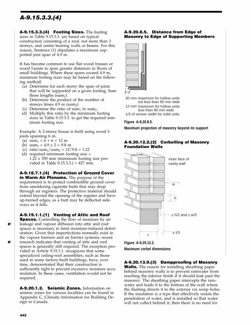
A-9.15.3.3.(4)
A-9.15.3.3.(4) Footing Sizes. The footingsizes in Table 9.15.3.3. are based on typicalconstruction consisting of a roof, not more than 3storeys, and centre bearing walls or beams. For thisreason, Sentence (1) stipulates a maximum sup-ported joist span of 4.9 m.
It has become common to use flat wood trusses orwood I-joists to span greater distances in floors ofsmall buildings. Where these spans exceed 4.9 m,minimum footing sizes may be based on the follow-ing method:
(a) Determine for each storey the span of joiststhat will be supported on a given footing. Sumthese lengths (sum1).
(b) Determine the product of the number ofstoreys times 4.9 m (sum2).
(c) Determine the ratio of sum1 to sum2.(d) Multiply this ratio by the minimum footing
sizes in Table 9.15.3.3. to get the required min-imum footing size.
Example: A 2-storey house is built using wood I-joists spanning 6 m.
(a) sum1 = 6 + 6 = 12 m(b) sum2 = 4.9 x 2 = 9.8 m(c) ratio sum1/sum2 = 12/9.8 = 1.22(d) required minimum footing size =
1.22 x 350 mm (minimum footing size pro-vided in Table 9.15.3.3.) = 427 mm.
A-9.18.7.1.(4) Protection of Ground Coverin Warm Air Plenums. The purpose of therequirement is to protect combustible ground coverfrom smoldering cigarette butts that may dropthrough air registers. The protective material shouldextend beyond the opening of the register and haveup-turned edges, as a butt may be deflected side-ways as it falls.
A-9.19.1.1.(1) Venting of Attic and RoofSpaces. Controlling the flow of moisture by air
e leakage and vapour diffusion into attic and roofspaces is necessary to limit moisture-induced deteri-oration. Given that imperfections normally exist inthe vapour barriers and air barrier systems, recent
e research indicates that venting of attic and roofspaces is generally still required. The exception pro-vided in Article 9.19.1.1. recognizes that somespecialized ceiling-roof assemblies, such as thoseused in some factory-built buildings, have, overtime, demonstrated that their construction issufficiently tight to prevent excessive moisture accu-mulation. In these cases, ventilation would not berequired.
A-9.20.1.2. Seismic Zones. Information onseismic zones for various localities can be found inAppendix C, Climatic Information for Building De-sign in Canada.
A-9.20.8.5. Distance from Edge ofMasonry to Edge of Supporting Members
maximum for hollow unitsnot less than 90 mm wide
30 mm
12 mm maximum for hollow unitsless than 90 mm wide
1/3 of veneer width for solid units
Figure A-9.20.8.5.
Maximum projection of masonry beyond its support
A-9.20.12.2.(2) Corbelling of MasonryFoundation Walls
inner face of cavity wall
t≤ t/3
h
≤ h/2 and ≤ w/3
w
Figure A-9.20.12.2.
Maximum corbel dimensions
A-9.20.13.9.(3) Dampproofing of MasonryWalls. The reason for installing sheathing paperbehind masonry walls is to prevent rainwater fromreaching the interior finish if it should leak past themasonry. The sheathing paper intercepts the rain-water and leads it to the bottom of the wall wherethe flashing directs it to the exterior via weep holes.If the insulation is a type that effectively resists thepenetration of water, and is installed so that waterwill not collect behind it, then there is no need for
442

A-9.23.10.2.
dead load imposed by the concrete must be consid-ered. The addition of 51 mm of concrete toppingcan impose an added load of 0.8 to 1.2 kPa, de-pending on the density of the concrete.
ExampleAssumptions:- basic dead load = 0.5 kPa- topping dead load = 0.8 kPa- total dead load = 1.3 kPa- live load = 1.9 kPa- vibration limit per A-9.23.4.2.(2)
- deflection limit = 1/360- ceiling attached directly to joists, no bridging
The spacing of joists in the span tables can be con-servatively adjusted to allow for the increased loadby using the spans in Table A-1 for 600 mm spac-ing, but spacing the joists 400 mm apart. Similarly,floor beam span tables can be adjusted by using4.8 m supported length spans for cases where thesupported length equals 3.6 m.
A-9.23.8.3. Joint Location in Built-UpBeams
L
4
not more thanone joint per piecein each span
no joints permittedin the end spansin this location
1
1Lcolumn
bearing plateabove column
joints in not morethan half the membersat these locations
2L
L2
4( 150 mm)+–
–( 150 mm)+
Figure A-9.23.8.3.
Joint location in built-up beams
A-9.23.10.2. Bracing. Traditionally, diagonalbracing has been provided at the corners of woodframed walls to provide resistance against windracking forces. Laboratory tests have indicated,however, that the bracing that had been tradition-ally used contributed relatively little to the overallstrength of the wall. Most of the racking resistancewas in effect provided by the interior finish. Be-cause of this, the requirements for bracing weredeleted in the late 1950’s. (See “Shear Resistance ofWood Frame Walls,” by A.T. Hansen, BuildingPractice Note 61, Institute for Research inConstruction, National Research Council, Ottawa.)
Where the interior is not finished, however, bracingis necessary if the siding itself or the sheathing doesnot provide the required racking strength. If paneltype siding is used, or if the sheathing consists ofplywood, OSB, waferboard, gypsum board, diago-nal lumber, or fibreboard sheathing, additionalbracing is not considered necessary because of thewind bracing provided by these materials.
Where bracing is provided, it must be installed atroughly a 45� angle on each wall and in each storey,extending the full height of the storey. This type ofbracing provides considerably greater resistance towind forces than the traditional bracing, which wasfound to be relatively ineffective.
The permission to omit bracing assumes typicalhouse designs. Some buildings may have reducedresistance to racking forces as a result of their con-figuration. These include tall narrow buildings inexposed locations with large door or window open-ings located in the short sides. In such cases, rackingresistance can be improved by ensuring that pan-eled sections are placed adjacent to the openings.
The Code does not address the issue of bracing ofthe structure during construction. It is often neces-sary to provide temporary bracing until the interiorfinish or sheathing is installed; however, this is nota Code requirement.
447

A-9.23.10.4.(1)
448
A-9.23.10.4.(1) Fingerjoined Lumber. TheNLGA “Standard Grading Rules for Canadian Lum-ber,” referenced in 9.3.2.1. refers to two specialproduct standards, SPS-1,“Fingerjoined StructuralLumber,” and SPS-3, “ Fingerjoined Stud Lumber –Vertical Use Only,” produced by NLGA. Materialidentified as conforming to these standards is con-sidered to meet the requirements in this Sentencefor joining with a structural adhesive. Lumber fin-gerjoined in accordance with SPS-3 should be usedas a vertical end-loaded member in compressiononly, where sustained bending or tension-loadingconditions are not present, and where the moisturecontent of the wood will not exceed 19%. Finger-joined lumber may not be visually regraded orremanufactured into a higher stress grade even ifthe quality of the lumber containing fingerjointswould otherwise warrant such regrading.
A-9.23.10.6.(2) Single Studs at Sides ofOpenings
(a) (b)
Configurations which comply
(a) full height studs both sides(b) full height studs both sides and opening within stud space(c) opening within stud space
Configurations which do not comply
(a) opening wider than stud space without full height studs both sides(b) opening narrower than but not within stud space
(a) (b) (c)
Figure A-9.23.10.6.A.Single studs at openings in non-loadbearing interior walls
Configurations which comply
(a), (b), (c) openings all narrower than and within stud space; no two full stud space width openings in adjacent stud spaces
Configurations which do not comply
(a) opening wider than stud space(b) opening narrower than but not within stud space(c) two openings, full stud space width, in adjacent stud spaces
(a) (b) (c)
(a) (b) (c)
A-9.23.10.6.B.Single studs at openings in all other walls
A-9.23.13.11.(2) Wood Roof TrussConnections. Sentence 9.23.13.11.(2) requires thatthe connections used in wood roof trusses be de-signed in conformance with Subsection 4.3.1.Sentence 4.1.1.2.(2), which applies to all of Part 4,requires that the designer be a professional engineeror architect skilled in the work concerned. This hasthe effect of requiring that the trusses themselves bedesigned by professional engineers or architects. Al-though this is a departure from the usual practice inPart 9, it is appropriate, since wood roof trusses arecomplex structures which depend on a number ofcomponents (chord members, web members, cross-bracing, connectors) working together to functionsafely. This complexity precludes the standardiza-tion of truss design into tables comprehensiveenough to satisfy the variety of roof designs re-quired by the housing industry.
A-9.23.14.2.(4) Water Absorption Test. Amethod for determining water absorption is de-scribed in ASTM D 1037, “Evaluating the Propertiesof Wood-Base Fiber and Particle Panel Materials.”The treatment to reduce water absorption may beconsidered to be acceptable if a 300 mm x 300 mmsample when treated on all sides and edges doesnot increase in weight by more than 6% whentested in the horizontal position.
A-9.23.14.4.(2) OSB. The CSA Standard requiresthat Type O (aligned or oriented) panels be marked toshow the grade and the direction of face alignment.
A-9.23.17.2.(1) Sheathing Membrane beneathStucco. This article is intended to preclude the use, understucco, of sheathing paper saturated with coal tar sincethere is a tendency for the tar to bleed through the stuccoand cause stains. This is not a problem with the morecommonly used asphalt-impregnated sheathing paper.
A-9.23.17.4.(2) Detailing of Joints inExterior Insulating Sheathing. The shape of a
r
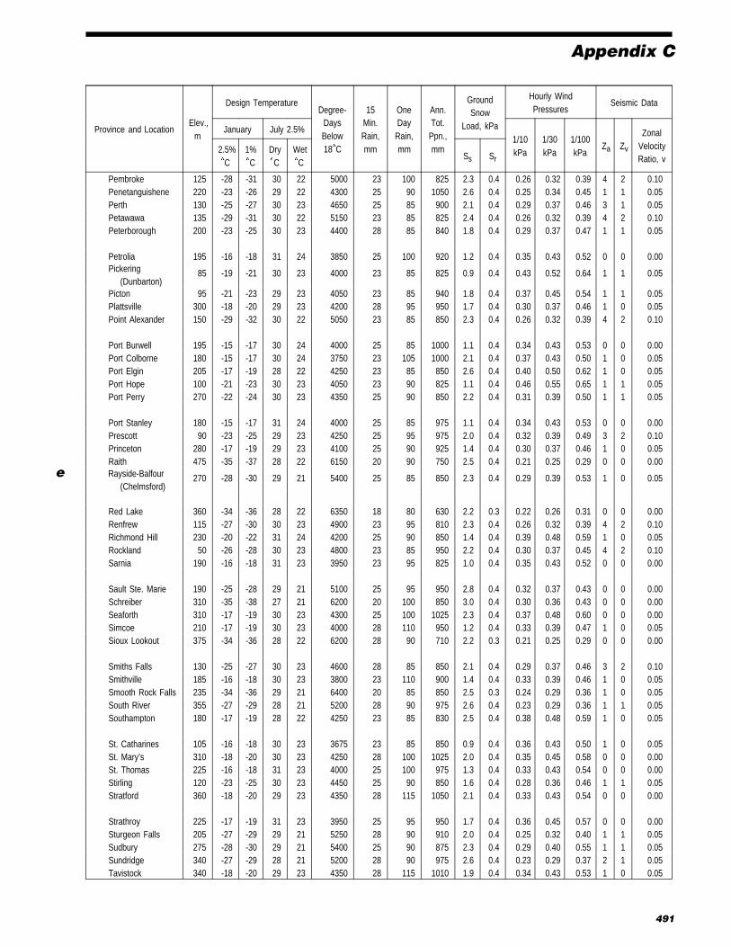
Appendix C
Design TemperatureHourly Wind
PressuresSeismic Data
January July 2.5%
GroundSnow
Load, kPaProvince and LocationElev.,
m2.5%�C
1%�C
Dry�C
Wet�C
Degree-DaysBelow18�C
15Min.Rain,mm
OneDay
Rain,mm
Ann.Tot.
Ppn.,mm
Ss Sr
1/10kPa
1/30kPa
1/100kPa
Za Zv
ZonalVelocityRatio, v
Pembroke 125 -28 -31 30 22 5000 23 100 825 2.3 0.4 0.26 0.32 0.39 4 2 0.10Penetanguishene 220 -23 -26 29 22 4300 25 90 1050 2.6 0.4 0.25 0.34 0.45 1 1 0.05Perth 130 -25 -27 30 23 4650 25 85 900 2.1 0.4 0.29 0.37 0.46 3 1 0.05Petawawa 135 -29 -31 30 22 5150 23 85 825 2.4 0.4 0.26 0.32 0.39 4 2 0.10Peterborough 200 -23 -25 30 23 4400 28 85 840 1.8 0.4 0.29 0.37 0.47 1 1 0.05
Petrolia 195 -16 -18 31 24 3850 25 100 920 1.2 0.4 0.35 0.43 0.52 0 0 0.00Pickering
(Dunbarton)85 -19 -21 30 23 4000 23 85 825 0.9 0.4 0.43 0.52 0.64 1 1 0.05
Picton 95 -21 -23 29 23 4050 23 85 940 1.8 0.4 0.37 0.45 0.54 1 1 0.05Plattsville 300 -18 -20 29 23 4200 28 95 950 1.7 0.4 0.30 0.37 0.46 1 0 0.05Point Alexander 150 -29 -32 30 22 5050 23 85 850 2.3 0.4 0.26 0.32 0.39 4 2 0.10
Port Burwell 195 -15 -17 30 24 4000 25 85 1000 1.1 0.4 0.34 0.43 0.53 0 0 0.00Port Colborne 180 -15 -17 30 24 3750 23 105 1000 2.1 0.4 0.37 0.43 0.50 1 0 0.05Port Elgin 205 -17 -19 28 22 4250 23 85 850 2.6 0.4 0.40 0.50 0.62 1 0 0.05Port Hope 100 -21 -23 30 23 4050 23 90 825 1.1 0.4 0.46 0.55 0.65 1 1 0.05Port Perry 270 -22 -24 30 23 4350 25 90 850 2.2 0.4 0.31 0.39 0.50 1 1 0.05
Port Stanley 180 -15 -17 31 24 4000 25 85 975 1.1 0.4 0.34 0.43 0.53 0 0 0.00Prescott 90 -23 -25 29 23 4250 25 95 975 2.0 0.4 0.32 0.39 0.49 3 2 0.10Princeton 280 -17 -19 29 23 4100 25 90 925 1.4 0.4 0.30 0.37 0.46 1 0 0.05Raith 475 -35 -37 28 22 6150 20 90 750 2.5 0.4 0.21 0.25 0.29 0 0 0.00
e Rayside-Balfour(Chelmsford)
270 -28 -30 29 21 5400 25 85 850 2.3 0.4 0.29 0.39 0.53 1 0 0.05
Red Lake 360 -34 -36 28 22 6350 18 80 630 2.2 0.3 0.22 0.26 0.31 0 0 0.00Renfrew 115 -27 -30 30 23 4900 23 95 810 2.3 0.4 0.26 0.32 0.39 4 2 0.10Richmond Hill 230 -20 -22 31 24 4200 25 90 850 1.4 0.4 0.39 0.48 0.59 1 0 0.05Rockland 50 -26 -28 30 23 4800 23 85 950 2.2 0.4 0.30 0.37 0.45 4 2 0.10Sarnia 190 -16 -18 31 23 3950 23 95 825 1.0 0.4 0.35 0.43 0.52 0 0 0.00
Sault Ste. Marie 190 -25 -28 29 21 5100 25 95 950 2.8 0.4 0.32 0.37 0.43 0 0 0.00Schreiber 310 -35 -38 27 21 6200 20 100 850 3.0 0.4 0.30 0.36 0.43 0 0 0.00Seaforth 310 -17 -19 30 23 4300 25 100 1025 2.3 0.4 0.37 0.48 0.60 0 0 0.00Simcoe 210 -17 -19 30 23 4000 28 110 950 1.2 0.4 0.33 0.39 0.47 1 0 0.05Sioux Lookout 375 -34 -36 28 22 6200 28 90 710 2.2 0.3 0.21 0.25 0.29 0 0 0.00
Smiths Falls 130 -25 -27 30 23 4600 28 85 850 2.1 0.4 0.29 0.37 0.46 3 2 0.10Smithville 185 -16 -18 30 23 3800 23 110 900 1.4 0.4 0.33 0.39 0.46 1 0 0.05Smooth Rock Falls 235 -34 -36 29 21 6400 20 85 850 2.5 0.3 0.24 0.29 0.36 1 0 0.05South River 355 -27 -29 28 21 5200 28 90 975 2.6 0.4 0.23 0.29 0.36 1 1 0.05Southampton 180 -17 -19 28 22 4250 23 85 830 2.5 0.4 0.38 0.48 0.59 1 0 0.05
St. Catharines 105 -16 -18 30 23 3675 23 85 850 0.9 0.4 0.36 0.43 0.50 1 0 0.05St. Mary’s 310 -18 -20 30 23 4250 28 100 1025 2.0 0.4 0.35 0.45 0.58 0 0 0.00St. Thomas 225 -16 -18 31 23 4000 25 100 975 1.3 0.4 0.33 0.43 0.54 0 0 0.00Stirling 120 -23 -25 30 23 4450 25 90 850 1.6 0.4 0.28 0.36 0.46 1 1 0.05Stratford 360 -18 -20 29 23 4350 28 115 1050 2.1 0.4 0.33 0.43 0.54 0 0 0.00
Strathroy 225 -17 -19 31 23 3950 25 95 950 1.7 0.4 0.36 0.45 0.57 0 0 0.00Sturgeon Falls 205 -27 -29 29 21 5250 28 90 910 2.0 0.4 0.25 0.32 0.40 1 1 0.05Sudbury 275 -28 -30 29 21 5400 25 90 875 2.3 0.4 0.29 0.40 0.55 1 1 0.05Sundridge 340 -27 -29 28 21 5200 28 90 975 2.6 0.4 0.23 0.29 0.37 2 1 0.05Tavistock 340 -18 -20 29 23 4350 28 115 1010 1.9 0.4 0.34 0.43 0.53 1 0 0.05
491

Appendix C
Design TemperatureHourly Wind
PressuresSeismic Data
January July 2.5%
GroundSnow
Load, kPaProvince and LocationElev.,
m2.5%�C
1%�C
Dry�C
Wet�C
Degree-DaysBelow18�C
15Min.Rain,mm
OneDay
Rain,mm
Ann.Tot.
Ppn.,mm
Ss Sr
1/10kPa
1/30kPa
1/100kPa
Za Zv
ZonalVelocityRatio, v
Temagami 300 -30 -33 30 21 5400 25 85 875 2.4 0.4 0.27 0.34 0.42 2 1 0.05Thamesford 280 -18 -20 30 23 4200 28 100 975 1.7 0.4 0.33 0.43 0.55 0 0 0.00Thedford 205 -16 -18 31 23 3900 23 95 900 1.9 0.4 0.41 0.50 0.61 0 0 0.00Thunder Bay 210 -31 -33 28 21 5650 20 100 710 2.7 0.4 0.30 0.36 0.43 0 0 0.00Tillsonburg 215 -17 -19 30 23 4000 25 95 980 1.2 0.4 0.31 0.39 0.50 0 0 0.00
Timmins 300 -34 -36 30 21 6200 18 95 875 2.8 0.3 0.25 0.32 0.40 1 0 0.05Timmins
(Porcupine)295 -34 -36 30 21 6200 18 90 875 2.7 0.3 0.27 0.34 0.42 1 0 0.05
Toronto(Metropolitan)
Etobicoke 160 -20 -22 31 24 4050 26 95 800 1.0 0.4 0.39 0.48 0.59 1 0 0.05North York 175 -20 -22 31 24 4000 25 95 850 1.1 0.4 0.39 0.48 0.59 1 0 0.05
Scarborough 180 -20 -22 31 24 4000 25 85 825 1.1 0.4 0.39 0.48 0.59 1 0 0.05Toronto 105 -18 -20 31 23 3650 25 90 820 0.8 0.4 0.39 0.48 0.58 1 0 0.05
Trenton 80 -21 -23 29 23 4250 23 95 850 1.5 0.4 0.35 0.43 0.52 1 1 0.05Trout Creek 330 -27 -29 28 21 5300 28 95 975 2.5 0.4 0.24 0.29 0.36 2 1 0.05Uxbridge 275 -22 -24 30 23 4400 25 95 850 2.2 0.4 0.29 0.37 0.48 1 1 0.05
Vaughan(Woodbridge)
165 -20 -22 31 24 4250 26 105 800 1.0 0.4 0.39 0.48 0.59 1 0 0.05
Vittoria 215 -15 -17 30 24 3925 25 115 950 1.2 0.4 0.35 0.43 0.52 1 0 0.05Walkerton 275 -18 -20 30 22 4500 28 105 1025 2.5 0.4 0.35 0.45 0.57 1 0 0.05Wallaceburg 180 -16 -18 31 24 3700 28 90 825 0.8 0.4 0.32 0.39 0.48 0 0 0.00Waterloo 330 -19 -21 29 23 4300 28 110 925 1.8 0.4 0.27 0.34 0.42 1 0 0.05
Watford 240 -16 -18 31 24 3900 25 100 950 1.7 0.4 0.34 0.43 0.53 0 0 0.00Wawa 290 -35 -38 26 21 5800 20 95 950 3.8 0.4 0.30 0.36 0.43 0 0 0.00Welland 180 -15 -17 30 23 3800 23 95 975 2.0 0.4 0.33 0.39 0.47 1 0 0.05West Lorne 215 -16 -18 31 24 3850 28 95 900 1.2 0.4 0.34 0.43 0.53 0 0 0.00Whitby 85 -20 -22 30 23 4000 23 80 850 1.1 0.4 0.43 0.52 0.64 1 1 0.05
Whitby (Brooklin) 160 -20 -22 30 23 4200 23 80 850 1.7 0.4 0.38 0.48 0.59 1 1 0.05White River 375 -39 -42 28 21 6400 20 85 825 4.1 0.4 0.21 0.25 0.30 0 0 0.00Wiarton 185 -18 -20 28 22 4500 25 105 1000 2.5 0.4 0.33 0.43 0.55 1 0 0.05Windsor 185 -16 -18 31 24 3600 28 95 900 0.7 0.4 0.36 0.43 0.52 0 0 0.00Wingham 310 -18 -20 30 23 4350 28 100 1050 2.4 0.4 0.35 0.45 0.57 0 0 0.00
Woodstock 300 -18 -20 29 23 4100 28 105 930 1.7 0.4 0.31 0.39 0.50 1 0 0.05Wyoming 215 -16 -18 31 24 3850 25 95 900 1.5 0.4 0.35 0.43 0.52 0 0 0.00
QuebecActon-Vale 95 -24 -27 30 23 4800 20 100 1050 2.1 0.4 0.24 0.29 0.36 3 2 0.10Alma 110 -30 -32 29 21 5800 20 85 950 3.0 0.4 0.23 0.29 0.36 3 3 0.15Amos 295 -34 -36 28 21 6250 20 85 920 2.9 0.3 0.24 0.29 0.35 2 1 0.05Asbestos 245 -26 -28 29 22 4850 23 90 1050 2.6 0.5 0.26 0.32 0.39 2 2 0.10Aylmer 90 -25 -28 30 23 4700 23 90 900 2.3 0.4 0.30 0.37 0.46 4 2 0.10
Baie-Comeau 60 -27 -29 25 19 6050 18 85 1000 3.9 0.4 0.45 0.55 0.66 4 2 0.10Beauport 45 -25 -28 28 22 5200 20 100 1200 3.1 0.5 0.38 0.48 0.58 4 3 0.15Bedford 55 -23 -25 29 23 4600 23 80 1260 1.9 0.4 0.31 0.37 0.45 3 2 0.10Beloeil 25 -24 -26 30 23 4550 23 85 1025 2.2 0.4 0.28 0.34 0.41 3 2 0.10Brome 210 -24 -26 29 22 4800 23 90 1240 2.3 0.4 0.28 0.34 0.41 3 2 0.10
492

Appendix DFire-Performance Ratings
Section D-1 GeneralThe contents of this Appendix have been preparedon the recommendations of the Standing Committeeon Fire Performance Ratings, which was establishedby the Canadian Commission on Building and FireCodes (CCBFC) for this purpose.
D-1.1. Introduction
D-1.1.1. Scope
1) This fire-performance information is pre-sented in a form closely linked to the performancerequirements and the minimum materials specifica-tions of the National Building Code of Canada 1995.
2) The ratings have been assigned only aftercareful consideration of all available literature onassemblies of common building materials, wherethey are adequately identified by description. Theassigned values based on this information will, inmost instances, be conservative when compared tothe ratings determined on the basis of actual testson individual assemblies.
3) The fire-performance information set outin this Appendix applies to materials and assembliesof materials which comply in all essential detailswith the minimum structural design standards de-scribed in Part 4 of the National Building Code ofCanada. Additional requirements, where appropri-ate, are described in other Sections of this Appendix.
4) Section D-2 of this Appendix assigns fire-resistance ratings for walls, floors, roofs, columns
This Appendix is included for explanatory purposes only anddoes not form part of the requirements. The bold face referencenumbers that introduce each item do not relate to specific re-quirements in the Code.
and beams related to CAN/ULC-S101-M,“Fire Endurance Tests of BuildingConstruction and Materials,” and describes methodsfor determining these ratings.
5) Section D-3 assigns flame-spread ratingsand smoke developed classifications for surface ma-terials related to CAN/ULC-S102-M,“Test for Surface Burning Characteristicsof Building Materials and Assemblies,” andCAN/ULC-S102.2-M, “Test for SurfaceBurning Characteristics of Flooring, FloorCovering, and Miscellaneous Materials and Assem-blies.”
6) Section D-4 describes noncombustibilityin building materials when tested in accordancewith CAN4-S114-M, “Test for Determinationof Non-Combustibility in BuildingMaterials.”
7) Section D-5 contains requirements for theinstallation of fire doors and fire dampers in fire-rated stud wall assemblies and the installation offire stop flaps in fire-rated membrane ceilings.
8) Section D-6 contains background infor-mation regarding fire test reports, obsolete materialsand assemblies, assessment of archaic assembliesand the development of the component additivemethod.
D-1.1.2. Referenced Documents
1) Where documents are referenced in thisAppendix, they shall be the editions designated inTable D-1.1.2.
499

D-1.1.2.
500
Table D-1.1.2.Documents Referenced in Appendix D Fire-Performance Ratings
IssuingAgency Document Number Title of Document Reference
r ANSI A208.1-1993 Particleboard, Mat-Formed Wood Table D-3.1.1.A.
r ASTM C 36-97 Gypsum Wallboard D-1.5.1.Table D-3.1.1.A.
r ASTM C 37-95 Gypsum Lath D-1.5.1.
r ASTM C 330-97 Lightweight Aggregates for Structural Concrete D-1.4.3.(2)
r ASTM C 442-95 Gypsum Backing Board and Coreboard D-1.5.1.Table D-3.1.1.A.
r ASTM C 588-95a Gypsum Base for Veneer Plaster D-1.5.1.Table D-3.1.1.A.
r ASTM C 630/C 630M-96a Water Resistant Gypsum Backing Board D-1.5.1.Table D-3.1.1.A.
ASTM C 931M-95a Exterior Gypsum Soffit Board D-1.5.1.Table D-3.1.1.A.
r ASTM C 960-97 Predecorated Gypsum Board D-1.5.1.
CCBFC NRCC 30629 Supplement to the National Building Code of Canada 1990 D-6.2.D-6.3.D-6.4.
CGSB 4-GP-36M-1978 Carpet Underlay, Fibre Type Table D-3.1.1.B.
CGSB CAN/CGSB-4.129-93 Carpets for Commercial Use Table D-3.1.1.B.
CGSB CAN/CGSB-11.3-M87 Hardboard Table D-3.1.1.A.
CGSB CAN/CGSB-34.16-M89 Sheets, Asbestos-Cement, Flat, Fully Compressed Table D-3.1.1.A.
CGSB CAN/CGSB-51.60-M90 Cellulose Fibre Loose Fill Thermal Insulation D-2.3.4.(5)
CGSB CAN/CGSB-92.2-M90 Trowel or Spray Applied Acoustical Material D-2.3.4.(5)
r CSA A23.1-94 Concrete Materials and Methods of Concrete Construction D-1.4.3.(1)
r CSA A23.3-94 Design of Concrete Structures D-2.1.5.D-2.6.6.D-2.8.2.
CSA A82.5-M1978 Structural Clay Non-Load-Bearing Tile Table D-2.6.1.A.
CSA A82.22-M1977 Gypsum Plasters Table D-3.1.1.A.
CSA CAN/CSA-A82.27-M91 Gypsum Board D-1.5.1.Table D-3.1.1.A.
CSA A82.30-M1980 Interior Furring, Lathing and Gypsum Plastering D-1.7.2.(1)D-2.3.9.(1)Table D-2.5.1.
CSA A82.31-M1980 Gypsum Board Application D-2.3.9.
CSA A126.1-M1984 Vinyl Asbestos and Vinyl Composition Floor Tile Table D-3.1.1.B.
CSA A165.1-94 Concrete Masonry Units Table D-2.1.1.

D-1.1.5.
501
Table D-1.1.2. (Continued)
IssuingAgency
Document Number Title of Document Reference
CSA CAN/CSA-A247-M86 Insulating Fibreboard Table D-3.1.1.A.
CSA CAN/CSA-G312.3-M92 Metric Dimensions for Structural Steel Shapes and HollowStructural Sections
D-2.6.6.
e CSA O86.1-94 Engineering Design in Wood (Limit States Design) D-2.11.2.(1)D-2.11.2.(2)
CSA O121-M1978 Douglas Fir Plywood Table D-3.1.1.A.
CSA CAN/CSA-O141-91 Softwood Lumber D-2.3.6.(2)Table D-2.4.1.
CSA O151-M1978 Canadian Softwood Plywood Table D-3.1.1.A.
CSA O153-M1980 Poplar Plywood Table D-3.1.1.A.
e CSA O437.0-93 OSB and Waferboard Table D-3.1.1.A.
CSA CAN/CSA-S16.1-94 Limit States Design of Steel Structures D-2.6.6.
r NFPA 80-1995 Fire Doors and Fire Windows D-5.2.1.
ULC CAN/ULC-S101-M89 Fire Endurance Tests of Building Construction and Materials D-1.1.1.(4)D-1.12.1.D-2.3.2.
ULC CAN/ULC-S102-M88 Test for Surface Burning Characteristics of Building Materialsand Assemblies
D-1.1.1.(5)
ULC CAN/ULC-S102.2-M88 Test for Surface Burning Characteristics of Flooring, FloorCovering, and Miscellaneous Materials and Assemblies
D-1.1.1.(5)Table D-3.1.1.B.
ULC CAN4-S114-M80 Test for Determination of Non-Combustibility in BuildingMaterials
D-1.1.1.(6)D-4.1.1.D-4.2.1.
ULC S505-1974 Fusible Links for Fire Protection Service D-5.3.2.
r ULC CAN/ULC-S702-97 Thermal Insulation, Mineral Fibre, for Buildings Table D-2.3.4.A.Table D-2.3.4.D.D-2.3.5.Table D-2.6.1.E.D-6.4.
D-1.1.3. Applicability of Ratings
The ratings shown in this document apply if morespecific test values are not available. Theconstruction of an assembly that is the subject of anindividual test report must be followed in all essen-tial details if the fire resistance rating reported is tobe applied for use with this Code.
D-1.1.4. Higher Ratings
The authority having jurisdiction may allow higherfire-resistance ratings than those derived from this
Appendix, where supporting evidence justifies ahigher rating. Additional information is provided insummaries of published test information and the re-ports of fire tests carried out by the Institute forResearch in Construction, National ResearchCouncil of Canada, included in Section D-6, Back-ground Information.
D-1.1.5. Additional Information on FireRated Assemblies
Assemblies containing materials for which there isno nationally recognized standard are not included

D-1.1.5.
in this Appendix. Many such assemblies have beenrated by Underwriters’ Laboratories of Canada(ULC) or Warnock Hersey. The ULC information ispublished in their “List of Equipment and Materi-als,” Volume II, Building Construction. Copies ofthis document may be obtained from Underwriters’Laboratories of Canada, 7 Crouse Road, Scarbor-ough, Ontario M1R 3A9. The Warnock HerseyCertification Listings can be obtained from WarnockHersey, 3210 American Drive, Mississauga, OntarioL4V 1B3.
D-1.2. Interpretation of TestResults
D-1.2.1. Limitations
1) The fire-performance ratings set out inthis Appendix are based on those that would be ob-tained from the standard methods of test describedin the Code. The test methods are essentially ameans of comparing the performance of onebuilding component or assembly with another in re-lation to its performance in fire.
2) Since it is not practicable to measure thefire resistance of constructions in situ, they must beevaluated under some agreed test conditions. Aspecified fire-resistance rating is not necessarily theactual time that the assembly would endure in situin a building fire, but is that which the particularconstruction must meet under the specified methodsof test.
3) Considerations arising from departuresin use from the conditions established in the stan-dard test methods may, in some circumstances,have to be taken into account by the designer andthe authority having jurisdiction. Some of these con-ditions are covered at present by the provisions ofthe National Building Code.
4) For walls and partitions, the stud spac-ings previously specified as 16 or 24 inch have beenconverted to 400 and 600 mm, respectively, for con-sistency with other metric values; however, the useof equivalent imperial dimensions for stud spacingis permitted.
D-1.3. Concrete
D-1.3.1. Aggregates in Concrete
Low density aggregate concretes generally exhibitbetter fire performance than natural stone aggregateconcretes. A series of tests on concrete masonrywalls, combined with mathematical analysis of thetest results, has allowed further distinctions be-tween certain low density aggregates to be made.
D-1.4. Types of Concrete
D-1.4.1. Description
1) For purposes of this Appendix, concretesare described as Types S, N, L, L1, L2, L40S, L120Sor L220S as described in (2) to (8).
2) Type S concrete is the type in which thecoarse aggregate is granite, quartzite, siliceousgravel or other dense materials containing at least30% quartz, chert or flint.
3) Type N concrete is the type in which thecoarse aggregate is cinders, broken brick, blast fur-nace slag, limestone, calcareous gravel, trap rock,sandstone or similar dense material containing notmore than 30% of quartz, chert or flint.
4) Type L concrete is the type in which allthe aggregate is expanded slag, expanded clay, ex-panded shale or pumice.
5) Type L1 concrete is the type in which allthe aggregate is expanded shale.
6) Type L2 concrete is the type in which allthe aggregate is expanded slag, expanded clay orpumice.
7) Type L40S concrete is the type in whichthe fine portion of the aggregate is sand and lowdensity aggregate in which the sand does not ex-ceed 40% of the total volume of all aggregates in theconcrete.
8) Type L120S and Type L220S concretes arethe types in which the fine portion of the aggregateis sand and low density aggregate in which thesand does not exceed 20% of the total volume of allaggregates in the concrete.
D-1.4.2. Determination of Ratings
Where concretes are described as being of Type S,N, L, L1 or L2, the rating applies to the concrete con-taining the aggregate in the group that provides theleast fire resistance. If the nature of an aggregatecannot be determined accurately enough to place itin one of the groups, the aggregate shall be consid-ered as being in the group that requires a greaterthickness of concrete for the required fire resistance.
D-1.4.3. Description of Aggregates
1) The descriptions of the aggregates inType S and Type N concretes apply to the coarseaggregates only. Coarse aggregate for this purposemeans that retained on a 5 mm sieve using themethod of grading aggregates described inCSA A23.1, “Concrete Materials and Methods ofConcrete Construction.”
2) Increasing the proportion of sand as fineaggregate in low density concretes requires
502

D-2.3.4.
Table D-2.3.4.A.Time Assigned to Wallboard Membranes on Fire-Exposed
Side
Description of Finish Time, min
11.0 mm Douglas Fir plywood phenolic bonded 10(1)
14.0 mm Douglas Fir plywood phenolic bonded 15(1)
12.7 mm Type X gypsum wallboard 2515.9 mm Type X gypsum wallboard 40Double 12.7 mm Type X gypsum wallboard 80(2)
Notes to Table D-2.3.4.A.:(1) Non-loadbearing walls only, stud cavities filled with mineral wool
r conforming to CAN/ULC-S702, “Thermal Insulation, Mineral Fibre, forBuildings,” and having a mass of not less than 2 kg/m2, with no ad-ditional credit for insulation according to Table D-2.3.4.D.
(2) Applies to non-loadbearing steel framed walls only.
3) When the membrane on the fire-exposedside of a framed assembly falls off, there is a briefperiod before structural failure occurs during whichthe studs or joists are exposed directly to flame.
Table D-2.3.4.C. lists the times which have been as-signed to the framing members based on the timeinvolved between failure of the membrane and col-lapse of the assembly.
4) Preformed insulation of glass, rock orslag fibre provides additional protection to woodstuds by shielding the studs from exposure to thefire and thus delaying the time of collapse. The useof reinforcement in the membrane exposed to firealso adds to the fire resistance by extending thetime to failure. Table D-2.3.4.D. shows the time in-crements that may be added to the fire resistance ifthese features are incorporated in the assembly.
5) Cellulose fibre insulation conforming toCAN/CGSB-51.60-M, “Cellulose Fibre Loose FillThermal Insulation,” applied in conformance withCAN/CGSB-92.2-M, “Trowel or Spray AppliedAcoustical Material,” does not affect the fire-resistancerating of a steel stud wall assembly, providedthat it is sprayed to either face of the wall cavity.
Table D-2.3.4.B.Time Assigned for Contribution of Lath and Plaster Protection on Fire-Exposed Side, min (1)
Type of Plaster Finish
Type of Lath Plaster Thickness, mm Portland Cement andSand(2) or Lime and Sand
Gypsum and Sand orGypsum Wood Fibred
Gypsum and Perlite orGypsum and Vermiculite
13 — 35 5516 — 40 659.5 mm gypsum19 — 50 80(1)
19 20 50 80(1)
23 25 65 80(1)Metal26 30 80 80(1)
Notes to Table D-2.3.4.B.:(1) Values shown for these membranes have been limited to 80 min because the fire-resistance ratings of framed assemblies derived from these
Tables shall not exceed 1.5 h.(2) For mixture of Portland cement-sand plaster, see D-1.7.2.(2).
Table D-2.3.4.C.Time Assigned for Contribution of Wood or Light Steel Frame
Description of Frame Time Assigned to Frame, min
Wood studs 400 mm o.c. maximum 20Wood studs 600 mm o.c. maximum 15Steel studs 400 mm o.c. maximum 10Wood floor and wood roof joists 400 mm o.c. maximum 10Open web steel joist floors and roofs with ceiling supports 400 mm o.c. maximum 10Wood roof and wood floor truss assemblies 600 mm o.c. maximum 5
511

D-2.3.5.
Table D-2.3.4.D.Time Assigne d for Additiona l Protection
Description of Additional Protection Time Assigned,min
Add to the fire-resistance rating of wood stud walls, sheathed with gypsum wallboard or lath and plaster, ifthe spaces between the studs are filled with preformed insulation of rock or slag fibres conforming to
r CAN/ULC-S702, “Thermal Insulation, Mineral Fibre, for Buildings,” and with a mass of not less than 1.22 kg/m2
ofjwalljsurface (1)
15
Add to the fire-resistance rating of non-loadbearing wood stud walls, sheathed with gypsum wallboard or lathand plaster, if the spaces between the studs are filled with preformed insulation of glass fibres conforming to
r CAN/ULC-S702, “Thermal Insulation, Mineral Fibre, for Buildings,” and having a mass of not less than0.6jkg/m2j ofjwalljsurface
5
Add to the fire-resistance rating of plaster on gypsum lath ceilings if 0.76 mm diam wire mesh with 25 mm by25 mm openings or 1.57 mm diam diagonal wire reinforcing at 250 mm o.c. is placed between lath and plaster
30
Add to the fire-resistance rating of plaster on gypsum lath ceilings if 76 mm wide metal lath strips are placedover joints between lath and plaster
10
Add to the fire-resistance rating of plaster on 9.5 mm thick gypsum lath ceilings (Table D-2.3.4.B.) if supportsfor lath are 300 mm o.c.
10
Notes to Table D-2.3.4.D.:(1) There are no test data to justify the 15 min additional protection for preformed glass fibre insulation.
D-2.3.5. Considerations for VariousTypes of Assemblies
1) Interior vertical fire separations shall berated for exposure to fire on each side, and a mem-brane shall be provided on both sides of theassembly. In the calculation of the fire-resistancerating of such an assembly, however, no contribu-tion to fire-resistance can be assigned for amembrane on the non-fire-exposed side, since thismembrane may fail when the structural membersfail.
2) When an exterior wall assembly is re-quired to be rated from the interior side only, suchwall assemblies shall have an outer membrane con-sisting of sheathing and exterior cladding with
spaces between the studs filled with insulation con-forming to CAN/ULC-S702, “Thermal Insulation, rMineral Fibre, for Buildings,” and having a mass ofnot less than 1.22 kg/m2 of wall surface.
3) In the case of a floor or roof, the standardtest provides only for testing for fire exposure frombelow. Floor or roof assemblies of wood, light-gauge steel members or open-web steel joist framingshall have an upper membrane consisting of a sub-floor and finish floor conforming to Table D-2.3.5. orany other membrane that has a contribution to fireresistance of not less than 15 min in Table D-2.3.4.A.For the purposes of this requirement, it is not neces-sary to comply with note (1) to Table D-2.3.4.A.
512
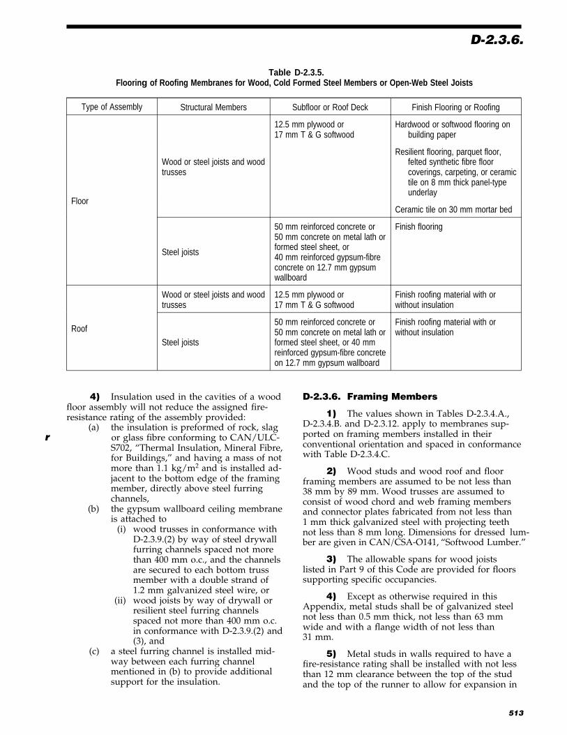
D-2.3.6.
Table D-2.3.5.Floorin g of Roofing Membranes for Wood, Cold Formed Steel Members or Open-Web Steel Joists
Type of Assembly Structural Members Subfloor or Roof Deck Finish Flooring or Roofing
Hardwood or softwood flooring onbuilding paper
Resilient flooring, parquet floor,felted synthetic fibre floorcoverings, carpeting, or ceramictile on 8 mm thick panel-typeunderlay
Wood or steel joists and woodtrusses
12.5 mm plywood or17 mm T & G softwood
Ceramic tile on 30 mm mortar bedFloor
Steel joists
50 mm reinforced concrete or50 mm concrete on metal lath orformed steel sheet, or40 mm reinforced gypsum-fibreconcrete on 12.7 mm gypsumwallboard
Finish flooring
Wood or steel joists and woodtrusses
12.5 mm plywood or17 mm T & G softwood
Finish roofing material with orwithout insulation
Roof
Steel joists
50 mm reinforced concrete or50 mm concrete on metal lath orformed steel sheet, or 40 mmreinforced gypsum-fibre concreteon 12.7 mm gypsum wallboard
Finish roofing material with orwithout insulation
4) Insulation used in the cavities of a woodfloor assembly will not reduce the assigned fire-resistance rating of the assembly provided:
(a) the insulation is preformed of rock, slagr or glass fibre conforming to CAN/ULC-
S702, “Thermal Insulation, Mineral Fibre,for Buildings,” and having a mass of notmore than 1.1 kg/m2 and is installed ad-jacent to the bottom edge of the framingmember, directly above steel furringchannels,
(b) the gypsum wallboard ceiling membraneis attached to
(i) wood trusses in conformance withD-2.3.9.(2) by way of steel drywallfurring channels spaced not morethan 400 mm o.c., and the channelsare secured to each bottom trussmember with a double strand of1.2 mm galvanized steel wire, or
(ii) wood joists by way of drywall orresilient steel furring channelsspaced not more than 400 mm o.c.in conformance with D-2.3.9.(2) and(3), and
(c) a steel furring channel is installed mid-way between each furring channelmentioned in (b) to provide additionalsupport for the insulation.
D-2.3.6. Framing Members
1) The values shown in Tables D-2.3.4.A.,D-2.3.4.B. and D-2.3.12. apply to membranes sup-ported on framing members installed in theirconventional orientation and spaced in conformancewith Table D-2.3.4.C.
2) Wood studs and wood roof and floorframing members are assumed to be not less than38 mm by 89 mm. Wood trusses are assumed toconsist of wood chord and web framing membersand connector plates fabricated from not less than1 mm thick galvanized steel with projecting teethnot less than 8 mm long. Dimensions for dressed lum-ber are given in CAN/CSA-O141, “Softwood Lumber.”
3) The allowable spans for wood joistslisted in Part 9 of this Code are provided for floorssupporting specific occupancies.
4) Except as otherwise required in thisAppendix, metal studs shall be of galvanized steelnot less than 0.5 mm thick, not less than 63 mmwide and with a flange width of not less than31 mm.
5) Metal studs in walls required to have afire-resistance rating shall be installed with not lessthan 12 mm clearance between the top of the studand the top of the runner to allow for expansion in
513

D-2.3.6.
the event of fire. Where attachment of the studs isnecessary for alignment purposes during erection,such attachment shall be made to the bottom run-ners only.
6) Except as required in D-2.3.5.(4), resilientor drywall furring channels may be used to attach agypsum wallboard ceiling membrane to a floor orroof assembly. The channels must be of galvanizedsteel not less than 0.5 mm thick, placed at a spacingof not more than 600 mm o.c. perpendicular to theframing members, with an overlap of not less than100 mm at splices and a minimum end clearancebetween the channels and walls of 15 mm.
D-2.3.7. Plaster Finish
The thickness of plaster finish shall be measuredfrom the face of gypsum or metal lath.
D-2.3.8. Edge Support for Wallboard
Gypsum wallboard installed over framing orfurring shall be installed so that all edges are sup-ported, except that 15.9 mm Type X gypsumwallboard may be installed horizontally with thehorizontal joints unsupported when framing mem-bers are at 400 mm o.c. maximum.
D-2.3.9. Membrane Fastening
1) Except as provided in (2) to (6), the ap-plication of lath and plaster finish shall conform toCSA A82.30-M, “Interior Furring, Lathing and Gyp-sum Plastering” and gypsum wallboard finish shallconform to CSA A82.31-M, “Gypsum Board Appli-cation.”
2) Where a membrane referred to in TablesD-2.3.4.A., D-2.3.4.B. and D-2.3.12. is applied to steelframing or furring, fasteners shall penetrate not lessthan 10 mm through the metal.
3) Except as provided in (4) and (5) where amembrane referred to in Tables D-2.3.4.A.,D-2.3.4.B. and D-2.3.12. is applied to wood framingor furring, minimum fastener penetrations intowood members shall conform to Table D-2.3.9. forthe time assigned to the membrane.
4) Where a membrane is applied in 2 layers,the fastener penetrations described in Table D-2.3.9.shall apply to the base layer. Fasteners for the facelayer shall penetrate not less than 20 mm into woodsupports.
Table D-2.3.9.Minimum Fastener Penetrations for Membrane Protection on Wood Frame, mm
Assigned Contribution of Membrane to Fire Resistance,(1) minType ofMembrane 5 – 25 30 – 35 40 50 55 – 70 80
Single layer 20 29 32 — — —Double layer 20 20 20 29 35 44Gypsum lath 20 20 23 23 29 29
Notes to Table D-2.3.9.:(1) Assigned contributions of membranes to fire resistance are determined in Tables D-2.3.4.A., D-2.3.4.B. and D-2.3.12.
5) Where adhesives are used to attach theface layer of gypsum wallboard in a double layerapplication for walls, the top and bottom of the facelayer shall be secured to the supports by mechanicalfasteners having lengths as required in (2) and (4)and spaced not more than 150 mm o.c. for woodsupports and not more than 200 mm o.c. for steelsupports.
6) In a double layer application of gypsumwallboard on wood supports, fastener spacing shallconform to CSA A82.31-M, “Gypsum Board Appli-cation.”
D-2.3.10. Ceiling Membrane Openings –Combustible Construction
1) Except as permitted in D-2.3.12., where afloor or roof assembly of combustible constructionis assigned a fire-resistance rating on the basis ofD-2.3. and incorporates a ceiling membrane de-scribed in Table D-2.3.4.A. or D-2.3.4.B., the ceilingmembrane may be penetrated by openings leadingto ducts within concealed spaces above the mem-brane provided:
(a) the assembly is not required to have afire-resistance rating in excess of 1 h,
(b) the area of any openings does not exceed930 cm2 (see (2)),
514

D-2.3.12.
(c) the aggregate area of openings does notexceed 1% of the ceiling area of the firecompartment,
(d) the depth of the concealed space abovethe ceiling is not less than 230 mm,
(e) no dimension of any opening exceeds310 mm,
(f) supports are provided for openings withany dimension exceeding 150 mm whereframing members are spaced greater than400 mm o.c.,
(g) individual openings are spaced not lessthan 2 m apart,
(h) the ducts above the membrane are sheetsteel and are supported by steel strap-ping firmly attached to the framingmembers, and
(i) the clearance between the top surface ofthe membrane and the bottom surface ofthe ducts is not less than 100 mm.
2) Where an individual opening permittedin (1) exceeds 130 cm2 in area, it shall be protectedby
(a) a fire stop flap conforming to D-5.3., or(b) thermal protection above the duct con-
sisting of the same materials as used forthe ceiling membrane, mechanically fas-tened to the ductwork and extending200 mm beyond the opening on all sides(see Figure D-2.3.10.).
100
mm
(min
.)
Figure D-2.3.10.
Thermal protection above a duct
D-2.3.11. Ceiling Membrane Openings –Noncombustible Construction
1) Except as permitted in D-2.3.12., where afloor or roof assembly of noncombustibleconstruction is assigned a fire-resistance rating onthe basis of D-2.3. and incorporates a ceiling mem-brane described in Table D-2.3.4.A. or D-2.3.4.B., theceiling membrane may be penetrated by openingsleading to ducts located within concealed spacesprovided:
(a) the area of any opening does not exceed930 cm2 (see (2)),
(b) the aggregate area of openings does notexceed 2% of the ceiling area of the firecompartment,
(c) no dimension of any opening exceeds400 mm,
(d) individual openings are spaced not lessthan 2 m apart,
(e) openings are located not less than200 mm from major structural memberssuch as beams, columns or joists,
(f) the ducts above the membrane are sheetsteel and are supported by steel strap-ping firmly attached to the framingmembers, and
(g) the clearance between the top surface ofthe membrane and the bottom surface ofthe duct is not less than 100 mm.
2) Where an individual opening permittedin (1) exceeds 130 cm2 in area, it shall be protectedby
(a) a fire stop flap conforming to D-5.3., or(b) thermal protection above the duct con-
sisting of the same materials as used forthe ceiling membrane, mechanically fas-tened to the ductwork and extending200 mm beyond the opening on all sides(see Figure D-2.3.10.).
D-2.3.12. Ceiling Membrane Rating
Where the fire-resistance rating of a ceiling assem-bly is to be determined on the basis of themembrane only and not of the complete assembly,the ratings may be determined from Table D-2.3.12.,provided no openings are located within the ceilingmembrane.
515
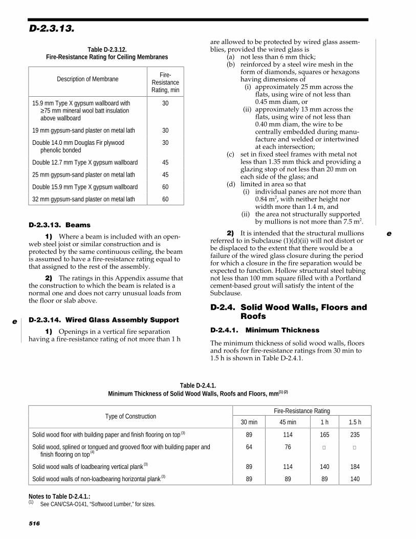
D-2.3.13.
516
Table D-2.3.12.Fire-Resistance Rating for Ceiling Membranes
Description of MembraneFire-
ResistanceRating, min
15.9 mm Type X gypsum wallboard with≥75 mm mineral wool batt insulationabove wallboard
30
19 mm gypsum-sand plaster on metal lath 30
Double 14.0 mm Douglas Fir plywoodphenolic bonded
30
Double 12.7 mm Type X gypsum wallboard 45
25 mm gypsum-sand plaster on metal lath 45
Double 15.9 mm Type X gypsum wallboard 60
32 mm gypsum-sand plaster on metal lath 60
D-2.3.13. Beams
1) Where a beam is included with an open-web steel joist or similar construction and isprotected by the same continuous ceiling, the beamis assumed to have a fire-resistance rating equal tothat assigned to the rest of the assembly.
2) The ratings in this Appendix assume thatthe construction to which the beam is related is anormal one and does not carry unusual loads fromthe floor or slab above.
D-2.3.14. Wired Glass Assembly Support
1) Openings in a vertical fire separationhaving a fire-resistance rating of not more than 1 h
are allowed to be protected by wired glass assem-blies, provided the wired glass is
(a) not less than 6 mm thick;(b) reinforced by a steel wire mesh in the
form of diamonds, squares or hexagonshaving dimensions of
(i) approximately 25 mm across theflats, using wire of not less than0.45 mm diam, or
(ii) approximately 13 mm across theflats, using wire of not less than0.40 mm diam, the wire to becentrally embedded during manu-facture and welded or intertwinedat each intersection;
(c) set in fixed steel frames with metal notless than 1.35 mm thick and providing aglazing stop of not less than 20 mm oneach side of the glass; and
(d) limited in area so that(i) individual panes are not more than
0.84 m2, with neither height norwidth more than 1.4 m, and
(ii) the area not structurally supportedby mullions is not more than 7.5 m2.
2) It is intended that the structural mullionsreferred to in Subclause (1)(d)(ii) will not distort orbe displaced to the extent that there would be afailure of the wired glass closure during the periodfor which a closure in the fire separation would beexpected to function. Hollow structural steel tubingnot less than 100 mm square filled with a Portlandcement-based grout will satisfy the intent of theSubclause.
D-2.4. Solid Wood Walls, Floors andRoofs
D-2.4.1. Minimum Thickness
The minimum thickness of solid wood walls, floorsand roofs for fire-resistance ratings from 30 min to1.5 h is shown in Table D-2.4.1.
Table D-2.4.1.Minimum Thickness of Solid Wood Walls, Roofs and Floors, mm(1) (2)
Fire-Resistance RatingType of Construction
30 min 45 min 1 h 1.5 h
Solid wood floor with building paper and finish flooring on top (3) 89 114 165 235
Solid wood, splined or tongued and grooved floor with building paper andfinish flooring on top (4)
64 76
Solid wood walls of loadbearing vertical plank (3) 89 114 140 184
Solid wood walls of non-loadbearing horizontal plank (3) 89 89 89 140
Notes to Table D-2.4.1.:(1) See CAN/CSA-O141, “Softwood Lumber,” for sizes.
e
e

D-2.6.1.
Table D-2.6.1.A. (Continued)
(5) Hollow clay tiles and masonry mortar shall be reinforced with 1.19 mm diam wire mesh with 10 mm by 10 mm openings, laid in every horizontaljoint and lapped at corners.
(6) Hollow clay tiles shall conform to CSA A82.5-M, “Structural Clay Non-Load-Bearing Tile.”(7) 50 mm nominal hollow clay tile, reinforced with 1.19 mm diam wire mesh with 10 mm by 10 mm openings laid in every horizontal joint and cov-
ered with 19 mm gypsum-sand plaster and with limestone concrete fill in column spaces, has a 4 h fire-resistance rating.
Table D-2.6.1.B.Minimum Thickness of Plaster Protection to Steel Columns, mm
Fire-Resistance Rating(1)(2)
Description30 min 45 min 1 h 1.5 h 2 h 3 h 4 h
Gypsum-sand plaster on 9.5 mm gypsum lath(3) 13 13 13 20 — — —
Gypsum-perlite or vermiculite plaster on 9.5 mm gypsumlath(3)
13 13 13 20 25 — —
Gypsum perlite or vermiculite plaster on 12.7 mmgypsum lath(3)
13 13 13 20 25 32 50
Gypsum perlite or vermiculite plaster on double 12.7 mmgypsum lath(3)
13 13 13 20 25 25 32
Portland cement-sand plaster on metal lath(4)(5) 25 25 25 — — — —
Notes to Table D-2.6.1.B.:(1) Fire-resistance ratings of 30 min and 45 min apply to columns whose M/D ratio is 30 or greater. Fire-resistance ratings greater than 45 min ap-
ply to columns whose M/D ratio is greater than 60. Where the M/D ratio is between 30 and 60 and the required fire-resistance rating is greaterthan 45 min, the total thickness of protection specified in the Table shall be increased by 50%. (To determine M/D, refer to D-2.6.4.)
(2) Where the thickness of plaster over gypsum lath is 25 mm or more, wire mesh with 1.57 mm diam wire and openings not exceeding 50 mm by50 mm shall be placed midway in the plaster.
(3) Lath held in place by 1.19 mm diam wire wrapped around lath 450 mm o.c.(4) Expanded metal lath 1.36 kg/m2 fastened to 9.5 mm by 19 mm steel channels held in vertical position around column by 1.19 mm diam wire ties.(5) For mixture of Portland cement-sand plaster, see D-1.7.2.(2).
Table D-2.6.1.C.Minimum Thickness of Gypsum-Sand Plaster on Metal Lath Protection to Steel Columns, mm
Fire-Resistance RatingM/D(1)
30 min 45 min 1 h 1.5 h 2 h 3 h
30 to 60 16 16 32 — — —over 60 to 90 16 16 16 32 — —
over 90 to 120 16 16 16 25 39 —over 120 to 180 16 16 16 16 25 —
over 180 16 16 16 16 25 39
Notes to Table D-2.6.1.C.:(1) To determine the M/D ratio, refer to D-2.6.4.
519

D-2.6.1.
Table D-2.6.1.D.Minimum Thickness of Gypsum-Perlite or Gypsum-Vermiculite Plaster on Metal Lath Protection to Steel Columns, mm
Fire-Resistance RatingM/D(1)
30 min 45 min 1 h 1.5 h 2 h 3 h 4 h
30 to 60 16 16 20 32 35 — —over 60 to 90 16 16 16 20 26 35 45
over 90 to 120 16 16 16 16 26 35 45over 120 to 180 16 16 16 16 20 32 35
over 180 16 16 16 16 16 26 35
Notes to Table D-2.6.1.D.:(1) To determine the M/D ratio, refer to D-2.6.4.
Table D-2.6.1.E.Steel Columns with Sheet-Steel Membrane and Insulation as Shown in Figures D-2.6.1.(a) and D-2.6.1.(b)
Type of ProtectionSteel
Thickness,(1)
mmFastening(2) Insulation Fire-Resistance
Rating
See Figure D-2.6.1.(a) 0.51 No. 8 sheet-metal screws9.5 mm long, 200 mm o.c.
50 mm mineral wool batts(3) 45 min
See Figure D-2.6.1.(b) 0.64 Self-threading screws or No. 8sheet-metal screws, 600 mm
o.c.
2 layers 12.7 mm gypsumwallboard
1.5 h
See Figure D-2.6.1.(a) 0.64 No. 8 sheet-metal screws,9.5 mm long 200 mm o.c.
75 mm mineral wool batts,(3)
12.7 mm gypsum wallboard2 h
See Figure D-2.6.1.(b) 0.76 Crimped joint or No. 8 sheet-metal screws, 300 mm o.c.
2 layers 15.9 mm gypsumwallboard
2 h
Notes to Table D-2.6.1.E.:(1) Minimum thickness, galvanized or wiped-zinc-coated sheet-steel.(2) Sheet-steel shall be securely fastened to the floor and superstructure, or where sheet-steel cover does not extend floor to floor, fire stopping
shall be provided at the level where sheet-steel protection ends. In the latter case, an alternate type of fire protection shall be applied betweenthe fire stopping and the superstructure.
(3)r Conforming to CAN/ULC-S702, “Thermal Insulation, Mineral Fibre, for Buildings,” Type 1A, minimum density 30 kg/m3: column section and battswrapped with 25 mm mesh chicken wire.
Table D-2.6.1.F.Minimum M/D Ratio for Steel Columns Covered with Type X Gypsum Wallboard Protection (1)
Fire-Resistance RatingMinimum Thickness of Type X GypsumWallboard Protection,(2) mm 1 h 1.5 h 2 h 3 h
12.7 75 — — —15.9 55 — — —25.4 35 60 — —28.6 35 50 — —31.8 35 40 75 —38.1 35 35 55 —41.3 35 35 45 —
520
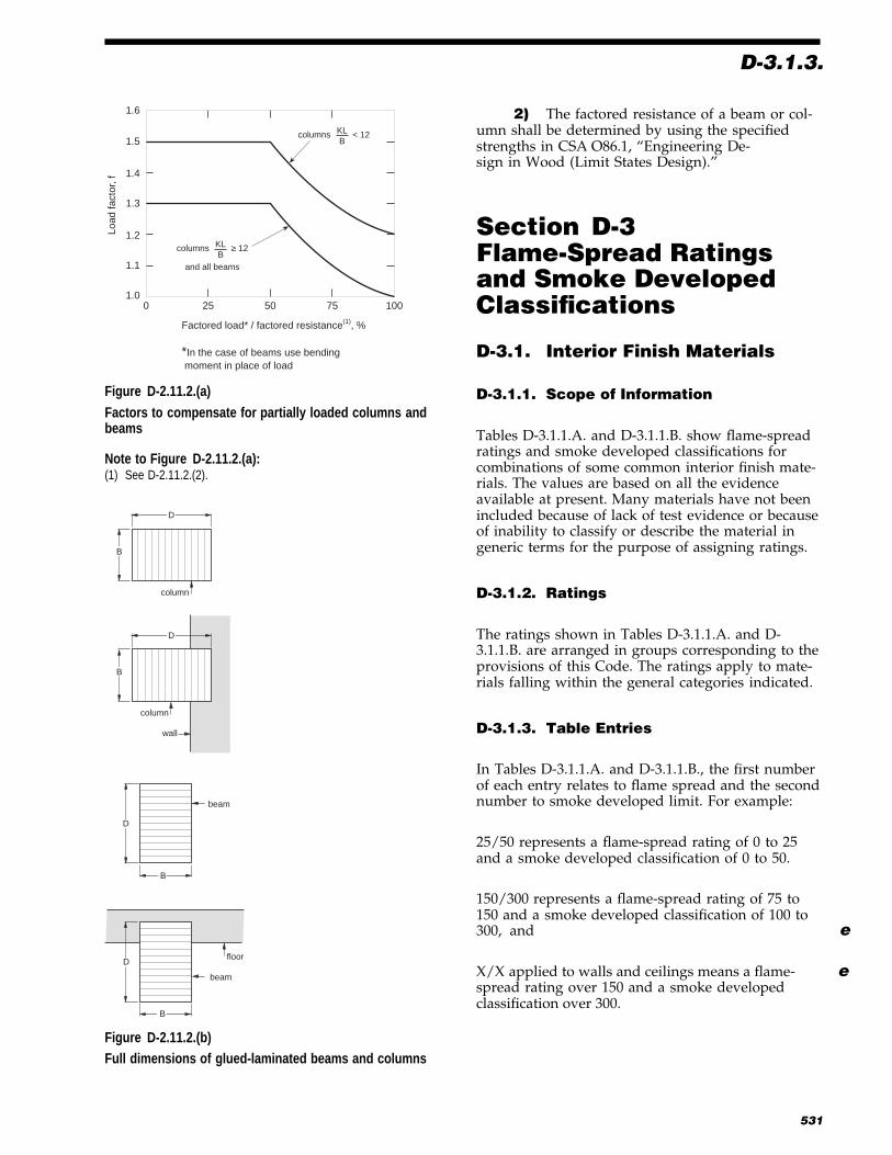
D-3.1.3.
10075502501.0
1.1
1.2
1.3
1.4
1.5
1.6Lo
ad fa
ctor
, f
Factored load* / factored resistance(1), %
*In the case of beams use bending moment in place of load
columns ≥ 12
and all beams
KLB
columns < 12KLB
Figure D-2.11.2.(a)Factors to compensate for partially loaded columns andbeams
Note to Figure D-2.11.2.(a):(1) See D-2.11.2.(2).
B
D
column
B
D
column
wall
B
D
beam
B
D
beam
floor
Figure D-2.11.2.(b)Full dimensions of glued-laminated beams and columns
2) The factored resistance of a beam or col-umn shall be determined by using the specifiedstrengths in CSA O86.1, “Engineering De-sign in Wood (Limit States Design).”
Section D-3Flame-Spread Ratingsand Smoke DevelopedClassifications
D-3.1. Interior Finish Materials
D-3.1.1. Scope of Information
Tables D-3.1.1.A. and D-3.1.1.B. show flame-spreadratings and smoke developed classifications forcombinations of some common interior finish mate-rials. The values are based on all the evidenceavailable at present. Many materials have not beenincluded because of lack of test evidence or becauseof inability to classify or describe the material ingeneric terms for the purpose of assigning ratings.
D-3.1.2. Ratings
The ratings shown in Tables D-3.1.1.A. and D-3.1.1.B. are arranged in groups corresponding to theprovisions of this Code. The ratings apply to mate-rials falling within the general categories indicated.
D-3.1.3. Table Entries
In Tables D-3.1.1.A. and D-3.1.1.B., the first numberof each entry relates to flame spread and the secondnumber to smoke developed limit. For example:
25/50 represents a flame-spread rating of 0 to 25and a smoke developed classification of 0 to 50.
150/300 represents a flame-spread rating of 75 to150 and a smoke developed classification of 100 to300, and e
X/X applied to walls and ceilings means a flame- espread rating over 150 and a smoke developedclassification over 300.
531

D-3.1.3.
Table D-3.1.1.A.Assigned Flame-Spread Ratings and Smoke Developed Classifications for Combinations of Wall and Ceiling Finish Materials
and Surface Coatings (1)
Surface Coating
Materials Applicable MaterialStandard
MinimumThickness, mm Unfinished
Paint or Varnish not morethan 1.3 mm Thick,
Cellulosic Wallpaper notmore than One Layer(2)(3)
Asbestos cement board CAN/CGSB-34.16-M NoneBrick, concrete, tile None NoneSteel, copper, aluminum None 0.33Gypsum plaster CSA A82.22-M None
0/0 25/50
CAN/CSA-A82.27-MASTM C 36
ASTM C 442ASTM C 588
r ASTM C 630/C 630M
Gypsum wallboard
r ASTM C 931/C 931M
9.5 25/50 25/50
Lumber None 16 150/300 150/300Douglas Fir plywood(4) CSA O121-MPoplar plywood(4) CSA O153-MPlywood with Spruce face veneer(4) CSA O151-M
11 150/100 150/300
Douglas Fir plywood(4) CSA O121-M 6 150/100 150/100Fiberboard low density CAN/CSA-A247-M 11 X/100 150/100Hardboard
Type 1 9 150/X (5)
StandardCAN/CGSB-11.3-M
6 150/300 150/300r Particleboard ANSI A208.1 12.7 150/300 (5)
e Waferboard CSA O437.0 — (5) (5)
Notes to Table D-3.1.1.A.:(1) See D-1.1.1.(5) for standards used to assign flame-spread ratings and smoke developed classifications.(2) Flame-spread ratings and smoke developed classifications for paints and varnish are not applicable to shellac and lacquer.(3) Flame-spread ratings and smoke developed classifications for paints apply only to alkyd and latex paints.(4) The flame-spread ratings and smoke developed classifications shown are for those plywoods without a cellulose resin overlay.(5) Insufficient test information available.
532
D-6.4.
and the remainder considered to be the contributionof the membrane.
The figures obtained for the contribution of mem-branes were then applied to the test results for openweb steel joist floors and wood and steel stud wallsand values of 20 min for the contribution of woodstud framing and 10 min for steel framing were de-rived.
The fire-resistance rating has been limited to 1.5 has this method of developing ratings for framed as-semblies was new and untried. Although this is thesubject of current review, no decision has beenmade to extend the ratings beyond 1.5 h.(1) M. Galbreath, G. C. Gosselin, and R. B.
Chauhan, Historical Guide to Chapter 2 of theSupplement to the National Building Code ofCanada, Committee Paper FPR 1-3, Preparedfor the Standing Committee on Fire Perfor-mance Ratings, May 1987.
Example showing fire-resistance rating of a typicalmembrane assembly, calculated using the compo-nent additive method.
1 hour Gypsum Board/Wood Stud Interior Parti-tion
A 1 h fire-resistance rating is required for an inte-rior wood framed partition, using 12.7 mm Type Xgypsum wallboard.
(a) Since gypsum wallboard is used (D-2.3.4.(2)and Table D-2.3.4.A.) time assigned to 12.7 mmType X gypsum wallboard membrane on thefire-exposed side of the partition = 25 min
(b) Time assigned to wood framing members at400 mm o.c. (D-2.3.4.(3) and Table D-2.3.4.C.) =20 min
(c) Time assigned to insulation, if the spaces be-tween the studs are filled with preformedinsulation of rock or slag fibres conforming to
r CAN/ULC-S702, “Thermal Insulation, MineralFibre, for Buildings,” (D-2.3.4.(4) and Table D-2.3.4.D.) = 15 min
(d) Time assigned to the membrane on the non-fire-exposed side (D-2.3.5.(1)) = 0 min
Fire-resistance rating = 25 + 20 + 15 = 60 min
537

538
Index
A
Abbreviationsproper names, 1.1.4.1.symbols and other abbreviations, 1.1.4.2.
Accessattic or roof space, 3.6.4.4., 9.19.2.1.crawl spaces, 3.6.4.6., 9.18.2.1., 9.18.4.1.fire dampers, 3.1.8.9.heating, ventilating and air-conditioning equip-
ment, 6.2.1.9., 9.18.4.1., 9.32.3.10., 9.33.4.2.horizontal service spaces, 3.6.4.5., 9.18.2.1.,
9.18.4.1., 9.19.2.1.ladders on chimneys, 6.3.1.5.
Access for fire fighting, 2.1.6.2., 3.2.2.10., 3.2.2.15.,3.2.5.1., 3.2.5.2., 3.2.5.4. – 3.2.5.6., 9.10.19.
basements, 3.2.5.2.roof area, 3.2.5.3.
Access openings, 8.2.1.3.heating, ventilating and air-conditioning systems,
6.2.1.12.Access panels, 3.2.5.1.Access route, 3.2.2.10., 3.2.5.5.Access to exit, 1.1.3.2., 3.3.1.11., 3.3.1.12., 3.3.1.18.,
3.3.2.5., 3.3.2.6., 3.4.6.15.capacity, 3.3.1.16., 9.9.3.corridor width, 3.3.1.9.doors in, 9.9.6.flame-spread rating, 9.10.20.6.floor areas (within), 3.3.1.3.headroom clearance, 3.3.1.8., 9.9.3.4.illumination, 9.9.11.2.residential occupancy, 3.3.4.4., 9.9.7., 9.9.9.roofs (from), 3.3.1.3., 9.9.2.1.width, 9.9.3.
Accessibility (see Barrier-free)Adfreezing, 1.1.3.2., 4.2.4.6.Adhesive
ceramic wall tiles, 9.29.10.3.ducts, 3.6.5.4., 9.33.6.4.
Administration of the Code, 1.1.1.Admixtures, concrete, 9.3.1.8.Aggregate
built-up-roofing, 9.26.11.4.concrete, 9.3.1.4.mortar, 9.20.3.1., 9.29.10.2.stucco, 9.28.2.2.
Aircirculation, 6.2.3.10., 9.33.6.7.
combustion, 9.32.3.6., 9.32.3.7., 9.33.6.14.distribution, 9.32.3.6., 9.32.3.7., 9.33.6.7., 9.33.6.12.flow through and around insulation, 5.3.1.3.,
9.19.1.3., 9.25.2.3., 9.25.2.4.leakage, 5.1.2.1., 5.4.1.1., 9.25.1.2.leakage resistance, 5.4.1.2., 9.13.1.3., 9.13.7.,
9.13.8., 9.18.6.2., 9.25.1.2.make-up, 9.32.3.8.outdoor, 9.32.3.6., 9.32.3.7.permeance, 5.3.1.3., 5.4.1.2.recirculation, 9.33.6.7.supply, 9.32.3.6., 9.32.3.7.tempering, 9.32.3.7., 9.32.3.8.transfer, 5.1.2.1., 5.2.2.1., 5.4.1.1.
Air barrier systems, 1.1.3.2., 5.1.2.1., 5.4., 9.25.1.2.,9.25.3.
assemblies in contact with the ground, 9.13.1.3.continuity, 5.4.1.2., 9.25.3.3.crawl space floors, 9.18.6.2.floors-on-ground, 9.13.8.1., 9.13.8.3., 9.18.6.2.installation, 9.23.2.2., 9.25.3.3.material standards, 9.13.2.2., 9.18.6.2., 9.25.3.2.requirement for, 5.4.1.1., 9.25.3.1.system properties, 5.4.1.2., 9.25.3.1., 9.25.3.2.walls in contact with the ground, 9.13.7.1.
Air-conditioning systems and equipment, 6.2.10.access, 6.2.1.9., 6.2.1.12., 9.33.4.2.accommodation of structural movement, 6.2.1.4.,
9.33.4.5.cleaning, 6.2.1.9., 9.33.4.2.design, 6.2.1., 9.33.1.1., 9.33.4.fire safety characteristics, 6.2.1.2., 9.33.6. – 9.33.8.installation, 6.2.1., 6.2.10.1., 9.33.1.1., 9.33.4.,
9.33.5.2., 9.33.9.1.installation standards, 6.2.1.5., 9.33.5., 9.33.5.2.protection from freezing, 6.2.1.9., 9.33.4.3.system pressure, 6.2.1.10., 9.33.4.4.
Air filters, 6.2.3.14., 9.33.6.15.Air inlets (see also Air intakes)
grills, 9.33.6.11.location, 9.33.6.11., 9.33.6.13.protection, 9.33.6.11.
Air intakes (see also Air inlets)area, 9.32.3.12.connection, 9.32.3.4. – 9.32.3.7.grills, 6.2.3.13.labeling, 9.32.3.12.location, 6.2.3.13., 9.32.3.4., 9.32.3.5., 9.32.3.7.,
9.32.3.12.protection, 6.2.3.13., 9.32.3.12.
539

Air outletsarea, 9.32.3.12.capacity, 6.2.4.4., 9.33.6.12.diffusers, 6.2.4.4., 9.33.6.11.grills, 6.2.3.13., 9.32.3.12.labeling, 9.32.3.12.location, 6.2.3.13., 6.2.4.4., 9.32.3.7., 9.32.3.12.,
9.33.6.11., 9.33.6.12.protection, 6.2.3.13., 9.32.3.12., 9.33.6.11.warm air heating, 6.2.4.4., 9.33.6.11., 9.33.6.12.
Air-supported structures, 1.1.3.2., 3.1.15.2., 9.10.1.3.assembly occupancy, 3.1.6.6.clearance, 3.1.6.3., 3.1.6.4.design basis, 4.4.1.emergency air supply, 3.1.6.6.flame resistance, 3.1.6.5.generator, 3.1.6.6.means of egress, 3.1.6.1.restrictions, 3.1.6.2.
Airborne sound rating, 9.11.Aisles, 3.3.2.4., 3.4.2.5., 3.4.3.4.Alarm signal, 1.1.3.2., 3.2.4.4., 3.2.4.6., 3.2.4.16.,
3.2.4.18., 3.2.4.19., 3.2.4.22., 3.2.5.15., 3.2.6.7.Alert signal, 1.1.3.2., 3.2.4.4., 3.2.4.16., 3.2.4.18.,
3.2.4.19., 3.2.4.22., 3.2.5.15., 3.2.6.7.Alterations, 1.1.2.1., 1.1.3.2.Alternative materials, 2.5.Aluminum
design basis for structures, 4.3.5.flashing, 9.20.13.1., 9.20.13.2., 9.26.4.1., 9.27.3.1.,
9.28.1.5.nails, 9.26.2.2.roofing, 9.26.13.1.siding, 9.27.12.1.
Anchorageagainst overturning, 4.1.4.4.anchor bolts, 9.20.11.6.columns, 9.23.6.2.concrete stairs, 9.8.10.2.cornices, 9.20.11.5.foundations (to), 9.23.6., 9.36.4.3.framing, 9.23.6.horizontal force factor for architectural compo-
nents, 4.1.9.1.horizontal force factor for mechanical/electrical
components, 4.1.9.1.masonry, 9.20.11.roofs, floors and intersecting walls, 9.20.11.sills, 9.20.11.5.small buildings, 9.23.6.3.walls to floors, 9.23.3.4.
Annunciators, fire alarm, 3.2.4.8., 3.2.4.16., 3.2.5.12.,3.2.5.15.
Appliances (see also Heating appliances, Heatingsystems and equipment, Heating, ventilatingand air-conditioning systems and equipment),1.1.3.2.
access to exit (in), 3.3.1.2.air-conditioning, 6.2.1., 9.33.4., 9.33.5.2.cooling, 6.2.1., 6.2.10.1., 9.33.4., 9.33.5.2., 9.33.9.1.exit (in), 3.4.4.4.
exterior, 3.6.1.4.fuel-fired, 3.6.2.1.heating, 6.2.1., 9.33.4., 9.33.5.2. – 9.33.5.4.location, 3.6.1.4., 6.2.5.1., 9.10.10.means of egress (in), 9.9.5.7.outdoor location, 6.2.1.9., 6.2.5.2.protection from freezing, 6.2.1.9., 9.33.4.3.roof top, 3.6.2.2., 9.10.1.4.solid-fuel burning, 3.6.2.1., 6.2.1.5., 9.33.5.3.ventilating, 6.2.1., 9.32.3.2.
Application of the National Building Code, 1.1.2.1.,2.1.
factory-built buildings, 2.1.4.1.farm buildings, 2.1.5.1.seasonally and intermittently occupied buildings,
2.1.3.1., 9.1.1.1.Areas and spaces, 9.5.Arena-type buildings, 3.1.2.3., 3.2.1.1., 3.2.2.17.
seating, 3.3.2.2.Artesian groundwater, 1.1.3.2.Asbestos cement
material standards, 9.27.8.1.pipe, 9.14.3.shingles, 9.27.8.siding, 9.23.17.6., 9.27.5.1., 9.27.8.
Asbestos in air distribution systems and equipment,6.2.1.11., 9.33.4.6.
Assembly areas, 4.1.6.3.Assembly occupancy (Group A), 1.1.3.2., 3.1.15.2.,
3.2.4.19., 3.2.7.3., 3.3.2.6.fire alarm systems, 3.2.4.1.fire protection, 3.2.2.17., 3.2.2.20. – 3.2.2.35.fire safety within floor areas, 3.3.1., 3.3.2.1.occupant load, 3.1.16.1.room or space classification, 9.10.1.3.
Assistive listening devices, 3.8.3.7.Attendant booths, 6.2.2.3.Attic or roof space, 1.1.3.2., 3.1.11.1., 3.1.11.5.,
3.2.3.3., 9.10.15.1., 9.10.16.10.access, 3.6.4.4., 9.19.2.fire protection, 9.10.12.5.venting, 9.19.1.
Attics, 3.6.1.1.floor loads, 4.1.6.3., 9.4.2.4.
Audible signal device, 3.2.4.19.Auditorium, 3.2.2.21., 3.2.2.22.Authority having jurisdiction, 1.1.3.2., 8.2.3.11.Automatic sprinkler systems
arena-type buildings, 3.1.2.3.assembly occupancy (Group A, Division 1),
3.2.2.20. – 3.2.2.22.assembly occupancy (Group A, Division 2),
3.2.2.23., 3.2.2.24., 3.2.2.26., 3.2.2.27.assembly occupancy (Group A, Division 3),
3.2.2.29., 3.2.2.31., 3.2.2.33.assembly occupancy (Group A, Division 4),
3.2.2.35.barrier-free floor areas, 3.3.1.7.business and personal services occupancy (Group
D), 3.2.2.49., 3.2.2.51., 3.2.2.52., 3.2.2.54.,3.2.2.56.
540

care or detention occupancy (Group B, Division1), 3.2.2.36., 3.2.2.37.
care or detention occupancy (Group B, Division2), 3.2.2.38. – 3.2.2.41.
combustible insulation, 3.1.5.11.combustible pipes, 3.1.5.15., 3.1.9.4., 3.2.5.14.construction, 3.2.5.13.contained use areas, 3.3.3.7.containment in basements, 3.2.1.5.controlled egress, 3.4.6.16.corridors, 3.1.13.6., 3.3.2.5.design, 3.2.5.13.egress doorways, 3.3.1.5.electrical supervision, 3.2.4.9.exceptions for mezzanines, 3.2.8.2.exposing building face, 3.2.3.2.fire alarm systems, 3.2.4.1., 3.2.4.7., 3.2.4.8.fire department connection, 3.2.5.16.fire fighting access, 3.2.5.1.fire separations in residential occupancy, 3.3.4.2.fire stopping, 3.1.11.5., 3.1.11.6.flame-spread rating, 3.1.13.8.garages, 3.3.5.4.heavy timber construction, 3.1.4.6., 3.2.2.16.high buildings, 3.1.13.7.high hazard industrial occupancy (Group F,
Division 1), 3.2.2.63. – 3.2.2.65.hold-open devices, 3.1.8.12.hose connections, 3.2.5.10.hose stations, 3.2.5.11.impeded egress, 3.2.2.19.in lieu of fire detectors, 3.2.4.15.installation, 3.2.5.13.interconnected floor space, 3.2.8.4.libraries, 3.3.2.11.limiting distance, 3.2.3.1.low hazard industrial occupancy (Group F,
Division 3), 3.2.2.73., 3.2.2.75., 3.2.2.77.,3.2.2.79., 3.2.2.81.
medium hazard industrial occupancy (Group F,Division 2), 3.2.2.67., 3.2.2.68., 3.2.2.70., 3.2.2.72.
mercantile occupancy (Group E), 3.2.2.57.,3.2.2.58., 3.2.2.60., 3.2.2.62.
metal roof deck, 3.1.14.2.multiple-tenant warehouses, 3.3.5.9.plans, 2.3.3.2.repair garages, 3.3.5.4.required, 3.2.2.18.residential occupancy (Group C), 3.2.2.42.,
3.2.2.43., 3.2.2.45., 3.2.2.48.separation of public corridors, 3.3.1.4.separation of suites, 3.3.1.1.service penetrations, 3.1.9.4.service spaces, 3.2.5.15.soffit protection, 3.2.3.15.stages, 3.3.2.12.standpipes, 3.2.5.8., 3.2.5.9.storage garages, 3.2.1.2., 3.3.5.4.storage rooms, 3.3.4.3.storeys below ground, 3.2.2.15.system monitoring, 3.2.4.16.
testing, 3.2.5.13.theatres (see Automatic sprinkler systems, stages)underground walkways, 3.2.3.19.unprotected openings, 3.2.3.1., 3.2.3.11., 3.2.3.13.,
3.2.3.14., 3.2.3.16.Awnings, 3.2.3.20.
B
Back draft prevention, 6.2.3.9.Backfill (see also Fill), 9.12.3.
material, 4.1.6.3., 9.12.3.3.stairs, 9.8.10.3.
Backfillinggrading, 9.12.3.2.placement, 4.2.2.3., 9.12.3.1.review, 4.2.5.8.stairs, 9.8.10.3.
Bacteria, minimizing growth, 6.2.2.4.Balance stops, 6.2.4.6., 9.33.6.10.Balconies, 3.1.11.5., 3.2.3.6.
access to exit (as), 9.9.9.3.construction of exterior, 3.2.2.11.exception to travel limit, 9.9.9.1.floor loads, 4.1.6.3., 4.1.6.4., 9.4.2.3.guards around, 9.8.8.horizontal exits, 3.4.6.9.occupant load, 3.1.16.1.snow loads, 9.4.2.3.
Banks, 3.4.6.16.Barricades, 8.2.1.3.Barrier-free, 1.1.3.2.
balconies, 3.3.1.7.counters, 3.8.3.14.design, 3.8., 9.5.2.doors, 3.8.3.3.elevators, 3.3.1.7., 3.5.2.1., 3.8.2.1., 3.8.3.5.entrances, 3.8.1.2.exterior walks, 3.8.3.2.floor areas, 3.8.2.1.floor surfaces, 3.8.1.3.lavatories, 3.8.3.11.parking areas, 3.8.2.2.path of travel, 9.5.2.2., 9.5.2.3.ramps, 3.8.3.4., 9.8.6.1.shower stalls, 3.8.3.13.signs, 3.8.3.1.soap and towel dispensers, 3.8.3.11.special washrooms, 3.8.3.12.telephone shelves, 3.8.3.15.urinals, 3.8.3.10.vestibules, 3.8.3.3.washrooms, 3.8.2.3., 3.8.3.1., 3.8.3.8., 3.8.3.11.water closets, 3.8.3.8., 3.8.3.9.wheelchairs, 3.8.2.1.width of path of travel, 3.8.1.3.
Barriers, across transparent panels, 3.3.1.18.Basements, 1.1.3.2.
access, 3.2.5.2.
541

access for fire fighting, 9.10.19.2.ceiling height, 9.5.3.1.crawl spaces considered as, 3.2.2.9., 9.10.8.8.exit signs, 3.4.5.2.fire containment, 3.2.1.5.fire protection, 3.2.2.15.fire-resistance of floor assemblies over, 3.2.1.4.fire separation, 9.10.9.4.heating requirements, 9.33.3.1.industrial occupancy (Group F), 3.3.5.3.insulation, 9.25.2.2.large or multi-storey, 9.10.1.3.lighting, 9.34.2.3., 9.34.2.4.residential occupancy (Group C), 3.2.2.42. –
3.2.2.48.storage garages, 2.1.6.2., 3.1.10.3., 3.2.1.2., 9.10.4.3.supply outlets, 9.33.6.12.
Bathroomsceiling height, 9.5.3.1.exhaust fan, 9.32.3.5.flame-spread rating, 3.1.13.3.
Beams, 9.4.1.2., 9.23.8.bearing, 9.23.8.1.built-up, 9.23.4.1., 9.23.4.4., 9.23.8.3.glued-laminated, 9.23.4.1., 9.23.4.4.lumber grade, 9.3.2.1.preservative treatment, 9.23.2.2., 9.23.2.3.ridge, 9.23.13.8.size, 9.23.4.1.span, 9.23.4.1., 9.23.4.4.steel, 9.23.4.2., 9.23.8.2.supported on masonry or concrete, 9.10.9.9.,
9.15.5., 9.20.8.3., 9.20.8.4., 9.21.5.3., 9.23.2.2.,9.23.2.3.
wood, 9.23.4.1., 9.23.4.4.Bearing surface, 1.1.3.2.Bedrooms
mechanical ventilation capacity, 9.32.3.3.natural ventilation area, 9.32.2.2.windows, 9.7.1.3.
Bleachersaisles, 3.3.2.4.guards, 3.3.2.8.inspection, 4.1.10.7.load analysis, 4.1.6.11.locking, 4.1.10.7.seats, 3.3.2.4.steps, 3.3.2.4., 3.3.2.10.
Boiler rooms, 3.6.2.3., 9.10.10.Boilers, installation standard, 6.2.1.5.Bonding
intersecting masonry walls, 9.20.11.2.masonry, 9.20.9.
Bookshelves, 3.2.8.2., 3.3.2.11.Bracing wood frame walls, 9.23.10.2.Breeching, 1.1.3.2.Bridging floor joists, 9.23.9.4.Builder (see Constructor)Building area, 1.1.3.2.
assembly occupancy (Group A, Division 1),3.2.2.20. – 3.2.2.22.
assembly occupancy (Group A, Division 2),3.2.2.23. – 3.2.2.28.
assembly occupancy (Group A, Division 3),3.2.2.29. – 3.2.2.34.
business and personal services occupancy (GroupD), 3.2.2.5., 3.2.2.49. – 3.2.2.56.
care or detention occupancy (Group B, Division1), 3.2.2.36., 3.2.2.37.
care or detention occupancy (Group B, Division2), 3.2.2.38. – 3.2.2.41.
determination, 2.1.6.1.determining fire safety requirements, 3.2.2.5.high hazard industrial occupancy (Group F,
Division 1), 3.2.2.63. – 3.2.2.66.low hazard industrial occupancy (Group F,
Division 3), 3.2.2.73. – 3.2.2.83.medium hazard industrial occupancy (Group F,
Division 2), 3.2.2.67. – 3.2.2.72.mercantile occupancy (Group E), 3.2.2.57. –
3.2.2.62.residential occupancy (Group C), 3.2.2.42. –
3.2.2.48.Building classification, 9.10.2.Building height, 1.1.3.2.
assembly occupancy (Group A, Division 1),3.2.2.20. – 3.2.2.22.
assembly occupancy (Group A, Division 2),3.2.2.23. – 3.2.2.28.
assembly occupancy (Group A, Division 3),3.2.2.29. – 3.2.2.34.
business and personal services occupancy (GroupD), 3.2.2.49. – 3.2.2.56.
care or detention occupancy (Group B, Division1), 3.2.2.36., 3.2.2.37.
care or detention occupancy (Group B, Division2), 3.2.2.38. – 3.2.2.41.
determination, 2.1.6.2., 9.10.4.determining fire safety requirements, 3.2.2.5.exceptions, 3.2.1.1.garages as separate buildings, 9.10.4.3.high hazard industrial occupancy (Group F,
Division 1), 3.2.2.63. – 3.2.2.66.low hazard industrial occupancy (Group F,
Division 3), 3.2.2.73. – 3.2.2.83.medium hazard industrial occupancy (Group F,
Division 2), 3.2.2.67. – 3.2.2.72.mercantile occupancy (Group E), 3.2.2.57. –
3.2.2.62.mezzanines as storeys, 9.10.4.1., 9.10.4.2.residential occupancy (Group C), 3.2.2.42. –
3.2.2.48.roof-top enclosures excluded, 9.10.4.4.
Building services, 3.2.4.2., 3.2.7.9.combustible, 3.1.9.2. – 3.1.9.4.demolition, 8.2.2.9.firewalls (in), 3.1.10.1.penetrating fire separations and fire-rated assem-
blies, 3.1.9.1. – 3.1.9.4., 9.10.9.6., 9.10.9.7.Building size and construction relative to occu-
pancy, 9.10.8.Building size determination, 2.1.6.
542
garages as separate buildings, 9.10.4.3.mezzanines as storeys, 9.10.4.1., 9.10.4.2.
Business and personal services occupancy (GroupD), 1.1.3.2.
classification, 3.1.2.1., 9.10.2.fire alarm systems, 3.2.4.1., 9.10.17.fire protection, 3.2.2.49. – 3.2.2.56.fire-resistance rating, 9.10.8.fire safety within floor areas, 3.3.1.flame-spread rating, 9.10.16.occupant load, 3.1.16.1.
C
Cables, 3.1.4.3., 3.1.5.17.elevator, 3.1.5.18.penetrating fire separations, 3.1.9.1., 3.1.9.3.plenums (in), 3.6.4.3.
Caisson (see Pile)Calculations and analysis
heat, air and moisture transfer, 5.2.2.1.heating, ventilating and air-conditioning equip-
ment and systems, 6.2.1.1., 9.33.4.1.structural, 2.3.4.5.wind load, 5.2.2.1.
Canopies, 3.2.3.16., 3.2.3.20.Capacity
exit (see also Exit width), 3.4.3.4.principle exhaust, 9.32.3.4.space heating appliances, 6.2.1.3., 9.33.5.1.supplemental exhaust, 9.32.3.5.ventilation, 9.32.3.3.
Carbon monoxideconcentration, 6.2.2.3.detectors, 6.2.2.3., 9.32.3.8.
Care facility, 3.1.2.5.Care or detention occupancy (Group B), 1.1.3.2.,
3.2.2.19., 3.2.4.21., 3.2.5.13., 3.3.3.1.classification, 3.1.2.1.fire alarm systems, 3.2.4.1.fire protection, 3.2.2.36. – 3.2.2.41.fire safety within floor areas, 3.3.1., 3.3.3.occupant load, 3.1.16.1.residential occupancy (as), 3.1.2.5., 9.10.2.2.sleeping rooms, 3.2.4.11.visual signal, 3.2.4.20.
Carpets, 3.1.13.1.Carports (see also Garages, open air), 9.35.
columns, 9.35.4.1., 9.35.4.2., 9.36.4.3.walls, 9.35.4.1., 9.36.4.3.
Caulking, 9.27.4.ceramic wall tile, 9.29.10.5.cladding, 9.23.17.6., 9.27.4., 9.27.9.4., 9.27.10.3.,
9.27.10.4., 9.27.11.3.door frames, 9.20.13.12.material properties, 9.27.4.2.material standards, 9.27.4.2., 9.29.10.5.siding, 9.23.17.6., 9.27.4., 9.27.9.4., 9.27.10.3.,
9.27.10.4., 9.27.11.3.
sill plates, 9.23.7.2.stucco, 9.28.1.5.window frames, 9.20.13.12.windows, 9.7.4., 9.7.4.2.
Cavity walls, 1.1.3.2., 9.20.6.2.corbelling, 9.20.12.2.flashing, 9.20.13.6.framing supported by, 9.20.8.2.lateral support, 9.20.10.1.mortar droppings, 9.20.13.11.tying, 9.20.9.4.
Ceiling membranescontribution to fire-resistance rating, 9.10.3.4.fire-resistance rating, 3.6.4.3.openings, 3.1.9.1., 3.1.9.5., 9.10.5., 9.10.9.6.,
9.10.9.7.supports, 3.6.4.3., 9.10.3.4.
Ceilingsassembly used as plenum, 3.1.9.6.fastened to floor joists, 9.23.9.5.finish, 9.29.framing around openings, 9.23.13.2.joists, 9.23.13.1., 9.23.13.3., 9.23.13.7. – 9.23.13.10.
Cement, standard for, 9.3.1.2.Central alarm and control facility, 3.2.4.22., 3.2.6.4.,
3.2.6.7., 3.2.6.9.Ceramic tile, 9.29.10., 9.30.6.
installation, 9.29.10.1. – 9.29.10.4.subfloor, 9.23.14.5.underlay, 9.23.14.5., 9.30.2.1., 9.30.2.2.
Chases, 9.20.7.Children’s custodial homes, 3.1.2.5., 3.2.4.3., 9.10.2.2.Chimneys, 1.1.3.2.
bracing, 9.21.4.5.caps, 9.21.4.6.cleanouts, 9.21.4.7.clearances, 9.21.5., 9.25.3.3.concrete, 6.3.1.2., 9.21., 9.33.10.2.concrete material for, 9.21.4.2.construction, 9.21.4.design of, 6.3.1.2., 9.20.2.3., 9.21., 9.33.10.2.factory-built, 1.1.3.2., 9.21.1.2.fireplace, 9.21.2.4. – 9.21.2.6.flashing, 9.21.4.6., 9.21.4.10., 9.26.4.3., 9.26.4.5.,
9.26.4.7.flues, 9.21.2., 9.21.4.4.footings, 9.21.4.3.fuel-fired appliances, 9.32.3.8.incinerators, 9.10.10.5., 9.21.2.1.lateral stability, 9.21.4.5.liners (see also Liners, chimney), 1.1.3.2., 9.21.3.,
9.21.4.9.masonry, 6.3.1.2., 9.21., 9.33.10.2.masonry material for, 9.21.4.1.masonry or concrete (see also Chimneys, con-
crete, Chimneys, masonry), 1.1.3.2., 9.21.metal, 6.3.1.3., 9.21.1.2.penetrating fire separations, 3.1.9.1.saddles, 9.26.4.7.sealing, 9.21.5.2.wall thickness, 9.21.4.8.
543

Chuteslinen, 3.6.3.3., 9.10.1.3.refuse, 3.6.3.3., 9.10.1.3.sprinklers, 3.6.3.3.venting, 3.6.3.3.
Cladding, 3.1.13.1., 3.2.3.7., 5.6., 9.27.attachment, 9.27.5.combustible, 3.1.5.5., 9.10.14.11., 9.10.14.12.,
9.10.14.14.fastening to steel studs, 9.24.1.4.installation, 5.6.1.3., 9.23.17.6., 9.27.5.requirement for, 5.6.1.1., 9.27.2.1.sealed, 5.6.2.1., 9.23.17.6.steel studs (on), 9.24.1.5.support, 9.20.5., 9.23.10.5., 9.24.3.4.
Cladding, asbestos-cement, 9.27.8.dimensions, weight, 9.27.8.2.fastening, 9.27.8.3.installation, 9.27.5., 9.27.8.3. – 9.27.8.5.material standards, 5.6.1.2., 9.27.8.1.
Cladding, asphaltinstallation, 9.27.5.venting, 9.27.2.4.
Cladding, clay tile, 5.6.1.2.Cladding, concrete
design, 9.20.6.6.weight and water absorption, 9.20.2.6.
Cladding, hardboard, 9.27.10.clearances, 9.27.10.5.dimensions, 9.27.10.2.installation, 9.27.5., 9.27.10.3. – 9.27.10.5.material standards, 5.6.1.2., 9.27.10.1.
Cladding, limestone, 9.20.6.6.Cladding, lumber, 9.27.6.
dimensions, 9.27.6.1.installation, 5.6.1.3., 9.20., 9.27.5., 9.27.6.2.material standards, 5.6.1.2., 9.20.2., 9.20.3.
Cladding, masonry, 9.20.bonding and tying, 9.20.9.flashing, 9.20.13.installation, 5.6.1.3.material standards, 5.6.1.2., 9.20.2.1.mortar joints, 9.20.4.support, 9.20.5.
Cladding, metal, 9.27.12.installation, 9.27.5.material standards, 5.6.1.2., 9.27.12.1.
Cladding, OSB and waferboard, 9.27.11.clearances, 9.27.11.4.dimensions, 9.27.11.2.installation, 9.27.5., 9.27.11.3., 9.27.11.4.material standards, 5.6.1.2., 9.27.11.1.
Cladding, plywood, 9.27.9.dimensions, 9.27.9.2.installation, 9.27.5., 9.27.9.3. – 9.27.9.5.material standards, 5.6.1.2., 9.27.9.1.sealing, 5.6.2.1., 9.27.9.3., 9.27.9.4.
Cladding, vinyl, 9.27.13.installation, 9.27.5., 9.27.13.2.material standards, 5.6.1.2., 9.27.13.1.
Cladding, waferboard (see Cladding, OSB andwaferboard)
Cladding, wood shingles and shakes, 9.27.7.material standards, 5.6.1.2., 9.27.7.1.
Clearancesabove ground, 9.3.2.9., 9.15.4.3., 9.23.2.2., 9.23.2.3.attic or roof spaces, 9.19.1.3.chimneys, 9.21.5., 9.25.3.3.cladding above ground, 9.27.2.2.cladding to roof, 9.27.2.3.combustible material, 6.2.3.6., 8.2.2.10., 8.2.3.9.,
9.22.10.3., 9.22.10.4., 9.33.6.8.cooling towers, 6.2.3.15.crawl spaces, 9.18.4.1.door and window frames, 9.27.10.5., 9.27.11.4.ducts, 6.2.3.6., 9.22.10.4., 9.33.6.8.electric and gas-fired ranges, 9.10.21.fireplaces, 9.22.10.furnace plenums, 6.2.3.6., 9.33.6.8.furnaces, 6.2.1.5., 9.33.5.2.gas vents, 9.25.3.3.hardboard siding, 9.27.10.5., 9.27.11.4.heating and air-conditioning equipment, 6.2.1.5.,
9.33.5.2.internal combustion engines, 8.2.2.10., 8.2.3.9.pipes, 6.2.9.3., 9.33.8.3.siding above ground, 9.27.2.2.siding to roof, 9.27.2.3.smoke chambers, 9.22.10.3.solid-fuel fired appliances, 6.2.1.5., 9.33.5.3.stucco, 9.28.1.4.supply ducts, 9.33.6.8.unit heaters, 6.2.7.
Climatic data, 2.2.Closures, 1.1.3.2., 3.1.8.1., 3.1.8.10., 3.2.3.1., 3.2.3.12.,
3.2.6.5.chutes, 3.6.3.3.door latches, 3.1.8.13.exterior wall openings, 3.2.3.5.fire dampers, 3.1.8.7., 9.10.13.13.fire-protection rating, 3.1.8.4., 9.10.13.1.fire separations (in), 3.2.8.2., 3.3.3.5., 9.10.9.3.,
9.10.13., 9.10.13.8.glass blocks, 3.1.8.14., 3.2.3.5., 9.10.13.5., 9.10.13.7.hold-open devices, 3.1.8.12., 9.10.13.11.installation, 3.1.8.5., 9.10.13.1.self-closing devices, 3.1.8.11.temperature limit, 3.1.8.15.wired glass, 3.1.8.14., 3.2.3.5., 9.10.13.5., 9.10.13.7.
Cold weather requirementsconcrete, 9.3.1.10.excavations, 9.12.1.3.gypsum board, 9.29.5.10.heating, ventilating and air-conditioning systems
and equipment, 9.33.4.3.masonry, 9.20.14.stucco, 9.28.6.1.
Collar ties, 9.23.13.7.Columns, 9.17.
carports, 9.35.3.4., 9.35.4.2., 9.36.4.3.concrete, 9.17.6.
544

fire separations, 3.1.8.10. – 3.1.8.13., 3.1.8.15.,3.3.3.5., 9.10.13.
flame-spread rating, 3.1.13.2., 3.1.13.7., 9.10.16.1.glass, 3.3.1.18., 9.6.6., 9.9.4.3.hardware, 3.1.8.11. – 3.1.8.13., 3.3.1.18., 3.3.3.5.,
3.4.6.15. – 3.4.6.17., 9.6.8., 9.9.6.3., 9.9.6.8. –9.9.6.10.
height and width, 9.6.3., 9.9.6.4.hold-open devices, 3.1.8.12., 9.10.13.11.incinerator rooms, 3.6.2.7.landings (at), 9.8.4.2.locking devices, 3.4.6.16., 3.4.6.17.means of egress (in), 3.3.1.12., 3.4.6.9., 3.4.6.10.,
9.9.6., 9.9.7., 9.10.13.obstructions, 9.9.6.2., 9.9.6.3.protection, 9.6.4.1.release hardware, 3.3.1.12., 3.3.2.6., 3.4.6.15.resistance to forced entry, 9.6.8.revolving, 3.4.6.14., 9.9.6.7.self-closing devices, 3.1.8.11., 9.10.13.10.,
9.10.13.15.service rooms, 3.6.2.7., 9.10.13.12.signs, 3.4.5.1.sill height, 9.6.4.1.sliding, 3.4.6.13., 5.3.1.2., 5.4.1.2., 9.6.5.2.standards for, 5.3.1.2., 5.4.1.2., 9.6.5., 9.10.13.2.steps or stairs (near), 3.4.6.10., 9.8.4.2., 9.9.6.6.storage garages, 9.9.6.5.storm, 5.3.1.2., 9.6.6.6.swing, 3.4.6.9., 3.4.6.11., 3.6.2.7.temperature limit, 3.1.8.15.thermal breaks, 5.3.1.2., 9.6.7.water closet rooms, 9.6.3.2.water closet stalls, 3.8.3.8.
Doorwaysbarrier-free path of travel, 3.8.3.3.dwelling unit and garage (between), 9.10.13.15.egress from suites, 3.3.1.3., 3.3.1.5., 9.9.7.1.,
9.9.7.3., 9.9.7.5., 9.9.8., 9.9.9.headroom clearance, 3.4.3.6.landings (at), 9.8.4.2., 9.8.6.3.means of egress (in), 3.3.1.5.near stairs, 9.8.4.2.ramp landings (at), 9.8.6.3.service rooms, 9.9.5.9.width, 3.3.3.4., 3.4.3.1.
Downspouts, 5.6.2.2., 9.26.18.1.Draft stop, 3.2.8.7.Drain, waste and vent piping (see also Plumbing),
3.1.9.4., 9.10.9.7.Drainage
above ground masonry walls, 9.20.13.10.building envelopes, 5.6.2.2.crawl spaces, 9.18.5.disposal, 5.6.2.2., 9.14.5.floors, 5.8.1., 9.16.3.3.floors-on-ground, 9.16.3.footings, 9.14.foundations, 5.8.1., 9.14.granular layers, 9.14.2.1., 9.14.4.granular material, 9.14.4.1.
installation of granular layer, 9.14.4.2., 9.14.4.4.installation of tiles and pipes, 9.14.3.3.pipes, 9.14.roofs, 5.6.2.2., 9.26.18.surface water, 9.12.3.2., 9.14.6.tile, 9.14.underground ducts (of), 6.2.3.5., 9.33.6.7.
Drainage systems, sanitary (see also Plumbing),1.1.3.2., 9.31.
Drainsfloors, 9.31.4.4.from noncombustible water closets, 9.10.9.7.roofs, 5.6.2.2., 9.26.18.2.
Drinking fountains, 3.8.3.16.Dry standpipes, 3.2.5.9.Dry wells, 9.14.5.3.Duct-type smoke detectors, 3.2.4.12., 9.10.17.4.Ducts, 9.33.6.
access, 6.2.1.9., 9.32.3.10., 9.33.4.2.access openings, 6.2.3.3.adhesives, 3.6.5.4., 9.33.6.4.aluminum, 9.33.6.5.branch, 3.1.8.8., 9.32.3.7.ceiling spaces (in), 3.1.9.5., 9.10.5.1.cleaning, 6.2.1.9., 9.32.3.10., 9.33.4.2.clearances, 3.6.5.6., 6.2.3.6., 9.22.10.4., 9.33.6.8.combustible, 3.1.5.14., 3.6.5.1., 9.33.6.2.connecting fire compartments, 3.1.8.7., 9.10.13.13.connections, 6.2.3.3., 9.33.6.6., 9.33.6.7.connectors, 3.6.5.1., 9.33.6.2., 9.33.6.6.construction, 6.2.3.3., 6.2.4.3., 9.33.6.5., 9.33.6.6.cooking equipment, 3.1.8.8.coverings, 3.6.5.4., 9.10.16.12., 9.33.6.4.design, 6.2.4.1., 6.2.4.2., 9.33.6.5.discharge, 9.32.3.10.drainage, 6.2.3.5., 9.33.6.7.exhaust, 3.1.8.8., 6.2.3.9., 9.10.9.18., 9.32.3.4.,
9.32.3.5., 9.32.3.10.exits (in), 6.2.3.11.fire rated assemblies (in), 3.1.9.5., 9.10.5.1.,
9.10.9.6.fire stops, 6.2.4.3.fittings, 6.2.4.6., 9.33.6.2., 9.33.6.5.galvanized, 9.33.6.5.horizontal service space access (in), 3.6.4.5.installation, 6.2.3.3., 6.2.4.3., 9.33.6.7.insulation, 3.1.5.14., 3.6.5.4., 9.32.3.10., 9.33.6.4.interconnection, 6.2.3.10., 9.33.6.7.joints, 6.2.3.3., 6.2.4.3., 9.33.6.3., 9.33.6.6., 9.33.6.7.leakage, 9.32.3.10.linings, 3.1.5.14., 3.6.5.4., 6.2.3.4., 9.10.16.12.,
9.33.6.4., 9.33.6.14.low capacity heating systems (for), 6.2.4.materials, 6.2.3.2., 9.32.3.10., 9.33.4.6., 9.33.6.2.metal, 6.2.4.2., 9.33.6.5.noncombustible, 3.1.8.8., 3.6.5.1.noncombustible construction, 3.1.5.14.penetrating fire separations, 3.1.8.8., 3.1.9.1.,
3.1.9.2., 9.10.9.6.penetrating fire stops, 3.1.11.7., 9.10.15.4.return, 6.2.4.3., 6.2.4.7., 9.33.6.7., 9.33.6.14.
547

sealing, 6.2.3.3.size, 6.2.4.1., 6.2.4.2., 9.32.3.4. – 9.32.3.7.slabs (in or beneath), 6.2.4.3., 6.2.4.5., 9.33.6.7.,
9.33.6.9.smoke detectors in, 6.2.3.8.supply, 6.2.3.10., 6.2.4.3. – 6.2.4.6., 9.32.3.6.,
9.32.3.7., 9.32.3.10., 9.33.6.7. – 9.33.6.9., 9.33.6.12.support, 6.2.4.3., 9.32.3.10., 9.33.6.6., 9.33.6.7.systems, 6.2.3., 9.33.6.trunk, 6.2.4.3., 9.32.3.7., 9.33.6.6., 9.33.6.7.underground, 6.2.3.5., 9.33.6.7.ventilation, 9.32.3.4. – 9.32.3.7., 9.32.3.10., 9.33.6.2.
Dumbwaiters, 3.5.1.1., 3.5.2.1., 3.5.3.2.Dusts, hazardous, 6.2.2.5.Dwelling units, 1.1.3.2., 3.3.4.1.
alarm audibility, 3.2.4.19.door swing, 3.4.6.11.egress, 3.3.4.4., 9.9.9.exception for combustible projections, 3.2.3.6.,
9.10.14.13.fire alarms, 3.2.4.1., 9.10.17.2.fire detectors, 3.2.4.10.fire protection, 3.2.2.42. – 3.2.2.48., 9.10.fire separations, 3.3.4.2., 9.10.guards, 3.3.4.7., 9.8.8.handrails, 3.3.4.7., 9.8.7.height of rooms and spaces, 3.7.1.1., 9.5.3.pull stations, 3.2.4.17.smoke alarms, 3.2.4.21., 9.10.18.sound control, 3.3.4.6., 9.11.sprinkler systems, 3.2.5.13.stairs, 3.3.4.7., 9.8.
E
Earthquake design, 4.1.9.analysis, 4.1.9.1.deflections, 4.1.9.2.foundations, 4.1.9.4.masonry walls, 9.20.1.2., 9.20.15.special provisions, 4.1.9.3.
Eave projections, 3.2.3.6., 9.10.14.13., 9.26.5.installation, 9.26.5.2.materials, 9.26.5.2.
Egress doorways, 3.3.1.5., 3.3.1.6.Egress from dwelling units, 3.3.4.4., 9.9.9.Electrical
equipment, 3.6.1.2., 9.33.5.2., 9.34.junction boxes, 3.1.5.2.outlet boxes, 3.1.5.2., 3.1.9.1. – 3.1.9.3., 9.10.5.1.,
9.10.9.6.raceways, 3.1.9.1., 3.1.9.2., 9.10.9.6.wiring, 3.6.1.2., 9.34.
Electromagnetic locking device, 3.4.6.15.Elevating devices, 3.8.2.1., 3.8.3.5.Elevators, 3.1.5.18., 3.2.6.4., 3.2.6.5., 3.5.1.1., 3.5.2.1.
barrier-free path of travel, 3.3.1.7., 3.8.2.1., 3.8.3.5.design, construction, installation and alteration,
9.10.1.3.
dimensions, 3.5.4.1.fire fighters, 3.2.7.9.flame-spread rating, 3.1.13.7.high buildings, 3.2.7.9.hoistways, 3.2.6.4., 3.2.6.6., 3.2.8.5., 3.3.4.6.,
3.5.3.1., 3.5.3.3., 3.5.4.2.machine rooms, 3.2.1.1., 3.2.2.14., 3.2.5.13., 3.5.3.3.recall, 3.2.4.14.
Emergency generator, 3.2.7.8., 3.2.7.9.Emergency lighting, 3.2.7.3., 9.9.11.3.Emergency power supply, 3.2.7.4. – 3.2.7.9., 9.9.11.3.Emergency recall, 3.2.6.4.Entrances, barrier-free, 3.8.1.2.Equipment
air-conditioning, 9.33.5.2.cooking, 3.3.1.2., 9.10.1.4.electrical installations, 9.33.5.2., 9.34.1.1.heating, ventilating and air-conditioning, 9.32.,
9.33.loads on floors and roofs, 4.1.6.3., 4.1.6.7.odour removal, 9.33.6.15.space cooling, 9.33.5.2., 9.33.9., 9.33.9.1.space heating, 9.33.5.
Equivalents, 2.5.materials, 2.5.1.test standards, 2.5.3.
Escalators, 3.2.8.2., 3.5.1.1., 3.5.2.1., 9.10.1.3.Excavations, 1.1.3.2.
depth, 9.12.2.design of, 4.2.5.grading, 9.14.4.3.native soil, 9.12.1.1.organic material, 9.12.1.1.protection from freezing, 9.12.1.3.water in, 9.12.1.2.
Exhaustcapacity, 9.32.3.4. – 9.32.3.8.discharge, 6.2.3.9., 9.32.3.10.fans, 9.32.3.4. – 9.32.3.8.garages (to), 6.2.3.9.intakes, 9.32.3.4. – 9.32.3.7., 9.32.3.10.outlets, 3.6.5.7., 6.3.3.9.systems, 3.2.6.6., 3.2.8.8., 3.3.1.19., 9.10.9.18.,
9.32.3.4., 9.32.3.5.Exhaust ducts, 1.1.3.2., 3.6.3.4., 9.10.9.18.
combining, 6.2.3.9.condensation, 6.2.3.9.insulation, 6.2.3.9.interconnection, 6.2.3.9.serving cooking equipment, 6.2.3.9.serving laundry equipment, 6.2.3.9.
Exhibition, 3.1.2.3.Existing buildings, application of Code, 1.1.2.1.Exit
level, 1.1.3.2., 3.2.6.2.storey, 1.1.3.2., 3.2.6.2.
Exits, 1.1.3.2., 3.1.13.10., 3.2.4.1., 3.2.4.11., 3.2.4.17.,3.2.5.10., 3.2.8.6., 9.9.
access, 3.4.6.16., 3.4.6.17., 9.9.2.1., 9.9.7.aggregate width, 3.4.3.1., 3.4.3.2., 3.4.3.4., 9.9.3.appliances, 9.9.5.7.
548

balconies, 3.4.4.1.capacity, 3.4.3.4.combustible glazing, 3.4.1.10.convergence, 3.4.1.2.cumulative width, 3.4.3.1., 3.4.3.3.doors, 3.2.3.12., 3.4.3.5., 3.4.6.10., 3.4.6.12.,
3.4.6.15., 9.9.6.ducts in, 6.2.3.11.dwelling units, 3.3.4.4., 9.9.9.emergency lighting, 3.2.7.3., 9.9.11.exterior passageways, 3.4.1.5.finish, interior, 9.10.16.fire separations, 3.4.4.1., 9.9.4.floor loads, 4.1.6.3.general requirements, 9.9.2.glass block, 3.2.3.12., 9.9.4.3. – 9.9.4.6.glass doors, 9.6.6., 9.9.4.3.glass panels, 3.4.1.8.hardware, 3.4.6.12., 3.4.6.15., 3.4.6.16.headroom clearance, 3.4.3.6., 9.8.3.4., 9.9.3.4.,
9.9.6.3.horizontal, 3.4.1.6., 9.9.2.2., 9.9.2.6.illumination, 3.2.7.1.integrity, 3.4.4.4., 9.9.4.2.interconnected floor space, 3.2.8.5., 3.4.3.3.lighting, 9.9.11.lobbies (through), 3.4.4.2., 9.9.8.5.location, 3.4.2.5., 9.9.8.4.mezzanine, 3.4.2.2., 3.4.4.1., 9.9.8.6.mirrors prohibited, 3.4.1.9., 9.9.5.6.number, 3.4.2.1., 9.9.2.1., 9.9.7.1., 9.9.8., 9.9.9.obstructions, 9.9.5., 9.9.6.2., 9.9.6.3.obstructions permitted, 3.4.3.5., 9.9.5.5.protected floor space, 3.2.8.6., 3.4.3.3.purpose, 9.9.2.5.ramps, 3.4.5.2., 9.8.6.revolving doors, 3.4.6.14.rooms opening into, 3.4.4.4., 9.9.5.9., 9.9.8.5.separation, 3.4.1.2., 3.4.2.3., 3.4.4.1.service rooms under, 3.6.2.3., 9.9.5.8.signs, 3.4.5.1., 3.4.5.2., 9.9.10.stairs, 3.4.5.2., 3.4.6.7., 9.8., 9.8.1.2.travel distance, 3.4.2.1., 3.4.2.3. – 3.4.2.5., 9.9.8.types, 3.4.1.4., 9.9.2.2.width, 3.4.3.5., 9.9.3.2., 9.9.3.3., 9.9.8.3.windows, 3.2.3.12., 3.4.6.5., 9.7.5.2., 9.9.4.wired glass, 3.2.3.12., 9.9.4.3. – 9.9.4.6.
Expansion and contractionelements in environmental separators, 5.1.4.1.heating and cooling systems, 6.2.1.10., 9.33.4.4.,
9.33.8.1.metal and vinyl siding, 9.27.5.6.piping, 6.2.9.1., 9.33.8.1.structural, 4.1.2.1.
Exposing building face, 1.1.3.2., 3.1.5.5., 3.2.3.2.,3.2.3.3., 3.2.3.5., 3.2.3.8., 3.2.3.10., 3.2.3.12. –3.2.3.16., 9.10.14.
area, 9.10.14.2.construction, 3.2.3.7., 9.10.14.7., 9.10.14.11.fire resistance waived, 9.10.14.12., 9.10.14.14.first storey facing a street, 9.10.14.9.
garage serving a dwelling unit, 9.10.14.14.restrictions on combustible projections, 3.2.3.6.,
9.10.14.13.unlimited openings, 3.2.3.9., 9.10.14.9., 9.10.14.10.unprotected openings, 3.2.3.1., 3.2.3.11., 9.10.14.1.,
9.10.14.8.Exterior walks, barrier-free path of travel, 3.8.3.2.Exterior walls
fire-resistance rating, 3.1.7.2., 3.1.7.3., 3.2.3.7.,3.2.3.10., 9.10.3.1., 9.10.3.3., 9.10.14.7., 9.10.14.11.
radiation, 3.1.7.2.restrictions on combustible projections, 3.2.3.6.,
9.10.14.13.Extinguishers, portable, 9.10.19.4.
construction sites (on), 8.2.3.4.demolition sites (on), 8.2.2.4.
F
Fabric, 3.2.3.20.Factories
floor loads, 4.1.6.7.storage areas, 4.1.6.3.
Factory-built chimneys, 1.1.3.2., 9.21.1.2.Falsework, 4.1.1.3.Fans, 3.2.6.2.
access, 6.2.1.9., 9.32.3.13., 9.33.4.2.auxiliary, 9.32.3.6.bathrooms, 9.32.3.5.capacity, 9.32.3.4. – 9.32.3.9.controls, 9.32.3.4. – 9.32.3.7.dehumidistat, 9.32.3.4., 9.32.3.5.exhaust, 9.32.3.4. – 9.32.3.8.installation, 6.2.3.16., 9.32.3.9., 9.32.3.13.kitchens, 9.32.3.5.location, 6.2.3.16.noise, 9.32.3.13.range-top, 9.32.3.10.sound ratings, 9.32.3.9.standards for, 9.32.3.9.supply, 9.32.3.6. – 9.32.3.8.vibration, 9.32.3.13.
Farm buildings, 1.1.3.2., 2.1.5.1.Fasteners
cladding, 9.27.5.4.gypsum board, 9.29.5.5. – 9.29.5.7.roofing, 9.26.2.2., 9.26.2.3.shingles, 9.26.7.4.siding, 9.27.5.4.size, 9.27.5.4.standard for, 9.23.3.1.stucco, 9.28.3.1., 9.28.3.2.
Fasteningcladding, 9.27.5.4.furring, 9.29.3.2.gypsum board, 9.29.5.8., 9.29.5.9.hardboard finish, 9.29.7.3.plywood finish, 9.29.6.3.sheathing, 9.23.3.5.
549

shingles, 9.26.7.4. – 9.26.7.6., 9.26.8.4., 9.26.8.5.siding, 9.27.5.4.steel framing, 9.24.3.6.steel studs (to), 9.24.1.4.stucco lath, 9.28.4.6.subflooring, 9.23.3.5.underlay, 9.30.2.3.wood frame construction, 9.23.3.wood shingles and shakes, 9.26.9.5., 9.26.10.3.
Fences, 8.2.1.3.Fibreboard
fastening, 9.29.8.3.installation, 9.29.8.3., 9.29.8.4.insulating finish, 9.29.8.material standard, 9.29.8.1.nailing, 9.29.8.3.roof sheathing, 9.23.15.6., 9.25.1.2.thickness, 9.29.8.2.wall sheathing, 9.23.16.2., 9.23.16.3., 9.25.1.2.
Fill (see also Backfill), 1.1.3.2.beneath floors-on-ground, 4.2.5.8., 9.16.2.1., 9.16.2.2.beneath footings, 4.2.5.8., 9.15.3.2.beneath foundations, 4.2.5.8.
Filters, 6.2.3.14.air, 9.33.6.15.
Finishes, interior, 3.1.5.10.ceilings, 9.29.fastening to steel studs, 9.24.1.4.flame spread limits, 9.10.16.floors, 9.30.gypsum board, 9.29.5.hardboard, 9.29.7.insulating fibreboard, 9.29.8.OSB, 9.29.9.particle board, 9.29.9.plywood, 9.29.6.steel studs (on), 9.24.1.5.tiles, 9.29.10.waferboard, 9.29.9.walls, 9.29.waterproof, 9.29.2.
Fire alarm and detection systems, 3.2.4.1., 3.2.4.4.,3.2.4.10., 3.2.4.13. – 3.2.4.15., 3.2.4.18., 3.2.4.21.,3.2.4.22., 3.2.5.15., 3.2.6.7., 3.2.6.9., 3.2.7.8.
annunciators, 3.2.4.8.audibility, 3.2.4.19.construction site, 8.2.3.8.continuity, 3.2.4.2.demolition site, 8.2.2.8.design, 3.2.4.5., 9.10.17.6.electrical supervision, 3.2.4.9.fire detectors, 3.2.4.4., 3.2.4.10.heat detectors, 9.10.17.hold-open devices, 3.1.8.12.installation, 3.2.4.5., 9.10.17.6.manual pull stations, 3.2.4.17.signal devices, 3.2.4.19.signal to fire department, 3.2.4.7.silencing, 3.2.4.6.single stage systems, 3.2.4.3., 3.2.4.4., 3.2.4.7.smoke detectors, 3.2.4.11., 3.2.4.12., 9.10.17.
testing, 3.2.4.5.two stage systems, 3.2.4.3., 3.2.4.4., 3.2.4.7.visual signal devices, 3.2.4.20.where required, 9.10.17.
Fire and sound resistance of walls, floors and ceil-ings, 9.10.3.1.
Fire chambers, 9.22.5.dimensions, 9.22.5.1.
Fire compartments, 1.1.3.2., 3.2.1.5., 3.2.3.1., 3.2.3.2.,3.2.3.12., 3.2.3.13., 3.2.4.8., 3.2.5.14., 3.2.6.9.
Fire curtains, 3.3.2.12.Fire dampers, 1.1.3.2., 3.1.8.5., 3.1.8.7., 3.1.8.8.,
6.2.3.7., 9.10.13.13., 9.24.3.7.access, 3.1.8.9.installation, 3.1.8.9.
Fire department, 3.2.4.7., 3.2.4.9., 3.2.5.4., 3.2.5.6.,3.2.6.7.
Fire department connection, 3.2.5.5., 3.2.5.9., 3.2.5.16.Fire detectors, 1.1.3.2., 3.2.4.4., 3.2.4.10.Fire escapes, 3.4.1.4.
access, 3.4.7.3.balconies, 3.4.7.3.closures, 3.4.7.4.construction, 3.4.7.2.dwelling units, 3.4.7.3.existing buildings, 3.4.7.1., 9.9.2.3.guards, 3.4.7.6.handrails, 3.4.7.6.headroom, 3.4.7.5.landings, 3.4.7.7.loads on, 4.1.6.3.means of egress, 9.9.2.4.protection, 3.4.7.4.scope, 3.4.7.1.stairs, 3.4.7.5.
Fire extinguishers, 3.2.5.17., 8.2.2.4., 8.2.3.4., 9.10.19.4.Fire fighters, 3.2.6.2., 3.2.6.5., 3.2.8.8.Fire fighting
access, 2.1.6.2., 3.2.2.10., 3.2.2.15., 3.2.5.5., 3.2.5.6.,8.2.2.3., 8.2.3.3., 9.10.19.
provisions, 9.10.19.Fire load, 1.1.3.2., 3.2.2.82.Fire protection, 3.2.3.8., 9.10.
construction camps, 9.10.20.crawl spaces, 9.18.7.electrical conductors, 3.2.6.9.exceptions, 3.2.2.3.gas and electric ranges, 9.10.21.structural, 3.2.2.3.
Fire protection components, 3.1.1.3.information, 2.3.3.
Fire-protection rating, 1.1.3.2., 3.1.8.5., 3.1.8.7.exceptions, 3.1.8.10., 9.10.13.2., 9.10.13.5., 9.10.13.7.tests, 3.1.8.4., 9.10.3.1.
Fire protection systems, 3.2.5.18.Fire pumps, 3.2.5.9., 3.2.5.19.Fire-resistance rating, 1.1.3.2., 3.1.7.1., 3.2.2.17.,
3.2.3.7.ceiling construction, 9.10.3.4.determination, 9.10.3.1.exterior walls, 3.1.7.3., 9.10.3.1., 9.10.3.3.
550
fire separations, 3.1.7.3.firewalls, 3.1.7.3., 3.1.10.2., 9.10.3.3.floor assemblies, 3.1.7.3., 3.2.1.4., 9.10.3.1., 9.10.8.interior walls, 3.1.7.3., 9.10.3.1., 9.10.3.3.loadbearing walls, 3.1.7.5., 9.10.8.3.rating of walls, floors, ceilings, 9.10.3.3.relation to occupancy and height, 9.10.8.roofs, 9.10.8.separations of suites, 3.3.1.1., 9.10.9.13., 9.10.9.14.steel framing, 9.24.2.4., 9.24.3.2.support of assemblies having, 9.10.8.3.supporting construction, 3.1.7.5., 9.10.8.3.test methods, 3.1.7.1., 9.10.3.1.vertical fire separations, 2.1.6.2., 9.10.3.3.waived, 9.10.8., 9.10.9., 9.10.14.windows and doors, 5.3.1.2.
Fire-retardant treated wood (see also Wood,fire-retardant treated), 1.1.3.2., 3.1.4.4., 3.1.5.10.,3.1.13.8., 3.2.2.25., 3.2.2.32., 3.2.2.53., 3.2.2.59.,3.2.2.69., 3.2.2.76.
roof system, 3.1.14.1.Fire safety
construction site, 8.2.3.demolition site, 8.2.2.in heating, ventilating and air-conditioning sys-
tems and equipment, 6.2.1.2., 9.33.6. – 9.33.8.size and occupancy, 9.10.8.
Fire separations, 1.1.3.2.airtightness of windows and doors in, 5.4.1.2.barrier-free floor areas, 3.3.1.7.between openings, 3.2.3.16.between zones in hospitals or nursing homes,
3.3.3.5.boarding and lodging houses, 9.10.9.14.building face (on), 3.2.3.2.building services, 3.1.9.1., 3.1.9.3., 3.1.9.4., 9.10.9.6.business and personal services occupancy, 3.3.1.1.care or detention occupancy, 3.3.3.1.closures, 3.1.8.1., 3.1.8.5., 9.10.13.containment in basements, 3.2.1.5.continuity, 3.1.8.1., 9.10.9.2., 9.10.11.2.crawl spaces, 3.2.2.9., 9.10.9.4.demolition sites, 8.2.2.13.dumb waiters, 3.5.3.2.dwelling units, 3.1.3.1., 3.3.4.2., 9.10.9.11.,
9.10.9.13.elevator machine rooms, 3.5.3.3.elevators, 3.2.6.5., 3.5.3.1.exits, 3.4.4.1., 9.9.4.firewalls, 3.1.10.1.floor assemblies, 3.3.4.2.floors over basements, 3.2.1.4.garages, 9.10.4.3., 9.10.9.16., 9.10.9.17.hold-open devices, 3.1.8.12.horizontal, 3.1.8.8.horizontal service spaces, 3.1.8.3., 3.6.4.2.,
9.10.9.10.industrial occupancy (group F), 3.3.5.1., 9.10.9.11.,
9.10.9.16., 9.10.9.17.integrity, 9.10.9.3.interconnected floor spaces, 3.1.3.1., 9.10.9.5.
libraries, 3.3.2.11.major occupancy, 3.1.3.1., 9.10.9.11., 9.10.9.16.,
9.10.9.17.meeting exterior walls, 3.2.3.13., 9.10.12.4.mercantile occupancy (group E), 3.1.3.1., 3.3.1.1.mezzanines, 3.2.8.1.multiple occupancy, 9.10.9.noncombustible, 3.1.8.2.occupancies, various, 9.10.9., 9.10.10.openings, 3.1.8.1., 3.1.8.6., 3.1.8.15., 3.2.8.2.,
9.10.13., 9.24.3.7.operating, recovery and delivery rooms, 3.3.3.6.penetrations, 3.1.9.3.protected floor spaces, 3.2.8.6.public corridors, 3.3.1.4., 9.10.9.15.rating, 3.1.7.3., 9.10.3.repair garages, 3.3.5.5.residential occupancy (group C), 3.1.3.1., 3.2.2.42.
– 3.2.2.48., 3.3.4.2., 9.10.9.11., 9.10.9.14.roof-top enclosures, 3.2.2.14.self-closing devices, 3.1.8.11.service penetrations, 3.1.9.2., 9.10.9.6.service rooms, 3.6.2.1., 9.10.8.4., 9.10.10.service rooms, exceptions for, 3.6.2.2.stages, 3.3.2.12.steel framing, 9.24.2.4., 9.24.3.7.storage garages, 3.2.1.2., 3.3.4.2., 3.3.5.6.storage rooms, 3.3.4.3., 9.10.10.6.storeys below ground, 3.2.2.15.suites, 3.3.1.1., 3.3.4.2., 9.10.9.13., 9.10.9.14.temperature rise and area limits, 3.1.8.17.thermal breaks in windows and doors in, 5.3.1.2.vehicular passageways, 3.2.3.17.vertical, 2.1.6.2., 3.1.8.3., 3.1.8.8.vertical service spaces, 3.6.3.1., 9.10.1.3.vestibules, 3.2.8.5.walkways, 3.2.3.18., 3.2.3.19.water tightness of windows and doors in, 5.6.1.2.
Fire stop flaps, 1.1.3.2., 3.6.4.3., 9.10.13.14.Fire stopping, 3.1.5.8., 3.1.11.5., 3.1.11.6., 3.2.3.15.Fire stops
combustible, 3.1.5.2.concealed spaces, 3.1.11., 9.10.15.ducts (around), 6.2.4.3.eave overhangs, 3.2.3.15.mansard style roofs, 9.10.15.1.materials, 3.1.5.2., 3.1.11.7., 9.10.15.3.pipes and ducts, 3.1.9.4., 9.10.9.6., 9.10.15.4.,
9.33.8.4.service penetrations, 3.1.9.1., 9.10.9.7.systems, 3.1.9.1., 3.1.9.4.
Fireplaces, 3.6.2.2., 6.2.1.6., 9.22., 9.32.3.8., 9.33.5.4.chimneys, 9.21.2.4.clearances, 9.22.10.combustion air, 9.22.1.4.concrete materials, 9.22.1.2.dampers, 9.22.7.1.factory-built, 9.22.9.fire chamber, 9.22.5.footings, 9.22.1.3.hearth, 9.22.6.
551

inserts, 9.22.11.liners, 9.22.2., 9.22.3.lintels, 9.22.4.1.masonry materials, 9.22.1.2.openings, 9.22.4.1.smoke chambers, 9.22.8.
Firewalls, 1.1.3.2., 3.1.9.1., 3.2.3.4., 3.2.4.2., 3.2.8.1.combustible projections, 3.1.10.7.construction, 9.10.11.continuity, 3.1.10.3.exterior walls, 3.1.10.6.fire-resistance rating, 3.1.7.3., 3.1.10.2., 9.10.3.3.,
9.10.11.3.openings, 3.1.10.5.parapets, 3.1.10.4.party walls as, 9.10.11.1.separating buildings, 2.1.6.1.structural stability, 3.1.10.1.support, 3.1.10.1.
First storey, 1.1.3.2., 3.2.2.15., 3.2.5.1., 3.2.8.2.Fixed seats, 3.3.2.3.Flags, 8.2.6.2.Flame-spread rating, 1.1.3.2., 3.1.5.10., 3.1.5.15.
bathrooms, 3.1.13.3.bathrooms within suites of residential occupancy,
9.10.16.11.business and personal services occupancy, 9.10.16.combustible glazing, 3.1.5.4.combustible insulation, 3.1.5.11., 9.10.16.10.,
9.10.16.12.combustible skylights, 3.1.5.4., 9.10.16.9.combustible vertical glazing, 9.10.16.1., 9.10.16.6.crawl spaces, 9.18.7.1.determination, 9.10.3.2.diffusers and grills, 9.33.6.11.doors, 3.1.13.2., 9.10.16.1.ducts, linings and coverings, 9.10.16.12., 9.33.6.4.elevator cars, 3.1.13.7.exits, 3.1.13.2., 3.1.13.7., 3.1.13.8., 9.10.11.3.,
9.10.16.exterior exit passageways, 3.1.13.10., 9.10.16.4.fire-retardant treated wood, 3.1.4.4.foamed plastic insulation, 3.1.5.11., 9.10.16.10.glazing and skylights, 3.1.13.2., 9.10.16.high buildings, 3.1.13.7.industrial occupancy, 9.10.16.insulation, 5.3.1.2., 9.25.2.2.insulation in concealed spaces, 9.10.16.interior finishes, 9.10.16.light diffusers and lenses, 3.1.13.4., 9.10.16.6.,
9.10.16.8.lobbies, 3.1.13.2., 9.10.16.3.mercantile occupancy, 9.10.16.pipe insulation and coverings, 9.33.8.2.public corridors, 3.1.13.6., 9.10.16.residential occupancy, 3.1.13.3., 9.10.16.service rooms, 3.1.13.7., 9.10.16.tests, 3.1.12.1., 9.10.3.2.vehicular passageways, 3.1.13.2.vestibules, 3.1.13.7.
Flammable liquids, 1.1.3.2., 8.2.2.4., 8.2.2.12., 8.2.3.4.,8.2.3.10.
Flash point, 1.1.3.2.Flashing, chimney
caps, 9.21.4.6.to other elements, 9.21.4.10.
Flashing, roof, 5.6.2.1., 9.26.4.built-up-roofing at cant strips, 9.26.11.10.built-up-roofing to masonry, 9.26.4.5.built-up-roofing to other than masonry, 9.26.4.6.materials, 9.26.4.1., 9.26.4.2.shingles to masonry, 9.26.4.3.shingles to other than masonry, 9.26.4.4.valley, 9.26.4.2.
Flashing, wall, 5.6.2.1., 9.27.3.below ground, 9.13.7.1.cavity walls, 9.20.13.6.fastening, 9.20.13.3.installation, 9.20.13.4., 9.27.3.2.masonry veneer, 9.20.13.7.masonry walls, 9.20.13.materials, 9.20.13.1., 9.20.13.2., 9.27.3.1.stucco, 9.28.1.5.
Floor area, 1.1.3.2.care or detention occupancy, 3.3.3.1.emergency access, 3.4.6.17.general requirements, 3.3.1.suites, 3.3.1.1.
Floor numbers, 3.5.4.2.Arabic numerals, 3.4.6.18., 9.9.10.9.exits, 3.4.6.18.
Flooring, 9.30.ceramic tile, 9.23.14.5., 9.30.6.parquet, 9.30.4.resilient, 9.23.14.6., 9.30.5.supports, 9.30.1.3.underlay, 9.30.2.water resistant, 9.30.1.2.wood strip, 9.23.14.5., 9.30.3.
Floorsacting as diaphragms, 4.1.9.1.anchorage of intersecting, 9.20.11.1.cantilevered, 9.23.9.10.combustible elements permitted, 3.1.5.8.fire separations, 9.10.9.4.fire-resistance rating, 9.10.8.1., 9.10.8.7.garages, 9.35.2.2.heavy timber construction, 3.1.4.6.joists, 9.23.4.1., 9.23.4.4., 9.23.9., 9.23.9.10.loads, 4.1.6., 9.23.1.1.ratings, 9.10.3.1.subfloors, 9.23.14.supports, 3.1.4.6., 3.2.1.4.vibrations, 4.1.1.6.
Floors-on-ground, 9.16.concrete, 9.16.4.dampproofing, 5.8.2., 9.13.1.1., 9.13.4.drainage, 5.8.1., 9.16.3.dwelling units (in), 9.16.1.3.hydrostatic uplift, 9.13.1.2.soil gas control, 5.4.1., 9.13.1.3., 9.13.8., 9.18.6.2.
552

openings through, 3.3.1.17., 3.4.6.5., 3.4.7.6.,9.8.8.4., 9.8.8.5.
porches, 9.8.8.2.ramps, 3.4.6.5., 3.8.3.4., 9.8.8.3.stairs, 3.4.6.5., 9.8.8.where required, 9.8.8.1.windows in exits, 9.7.5.2.windows in public areas, 3.3.1.18., 9.7.5.windows in residential occupancy, 9.7.1.6., 9.7.5.4.
Gypsum board, 3.1.11.7.application standard, 9.29.5.1.fasteners, 9.29.5.5.fastening, 9.29.5.8., 9.29.5.9.installation, 9.29.5.3. – 9.29.5.5., 9.29.5.8., 9.29.5.9.interior finish, 9.29.5.material standard, 9.29.5.2.thermal barrier, 3.1.5.11.wall sheathing, 9.23.16.2., 9.23.16.3.
Gypsum lath, 9.29.4.1.
H
Hallways, width within dwelling units, 9.5.4.Handrails, 9.8.7.
attachment, 9.8.7.8.continuity, 3.4.6.4., 9.8.7.2.dwelling unit, 3.3.4.7.ergonomic design, 9.8.7.5.graspable, 3.4.6.4., 9.8.7.5.height, 9.8.7.4.loading, 3.4.6.4.means of egress (in), 9.9.1.1.projection, 9.8.7.6.ramps, 3.4.6.4., 3.8.3.4., 9.8.7.7.stairs, 3.4.6.4.termination, 9.8.7.3.
Hardboardfastening, 9.29.7.3.installation, 9.29.7.3., 9.29.7.4.interior finish, 9.29.7.material standards, 5.6.1.2., 9.27.10.1., 9.29.7.1.nailing, 9.29.7.3.siding, 9.23.17.6., 9.27.10.thickness, 9.29.7.2.underlay, 9.30.2.2.
Hardware for doors, 3.1.8.5., 3.1.8.11., 3.1.8.12.,3.8.3.8., 3.8.3.12., 9.9.6.3., 9.9.6.10.
bolts, 9.6.8.4.closers, 3.8.3.3.door viewers, 9.6.8.8.height, 3.4.6.15.hinges, 9.6.8.5., 9.6.8.7.hold-open devices, 9.10.13.11.locks and latches, 9.6.8.3., 9.9.6.8., 9.9.6.9.,
9.10.13.9.power operators, 3.8.3.3.self-closing devices, 9.10.13.10., 9.10.13.15.strikeplates, 9.6.8.6.
Hazardous substances, 3.2.4.10., 3.3.1.2., 3.3.1.19.,3.3.5.3., 9.10.1.3., 9.10.17.3.
Headroom clearancedoorways, 3.4.3.6., 9.6.3.1.exits, 3.4.3.6., 9.9.3.4.stairways, 3.4.3.6., 9.8.3.4.
Hearths, fireplace, 9.22.6.extensions, 9.22.6.1.support, 9.22.6.2.
Heat detectors (see also Fire detectors, Smoke detec-tors), 1.1.3.2., 9.10.17.3.
Heat recovery ventilators, 6.2.1.7.access, 9.32.3.13.balancing, 9.32.3.11.capacity, 9.32.3.9., 9.32.3.11.condensate, 9.32.3.11.installation, 9.32.3.11., 9.32.3.13.standards for, 9.32.3.9., 9.32.3.11.
Heat transfer, 5.1.2.1., 5.2.2.1., 5.3.1., 5.3.1.2., 9.25.2.1.Heating appliances
capacity, 6.2.1.3., 9.33.3.1., 9.33.5.1.design, 6.2.5.2., 9.33.5.3.installation, 6.2.installation standards, 6.2.1.5., 9.33.5.2., 9.33.5.3.location, 6.2.5.1.
Heating coilsservice water heaters, 9.31.6.6.
Heating systems and equipmentaccess, 6.2.1.9., 9.33.4.2.asbestos in, 6.2.1.11., 9.33.4.6.capacity, 6.2.1.3., 9.33.3.1.cleaning, 6.2.1.9., 9.33.4.2.design, 6.2.1.1., 6.2.5.2., 9.33.1.1., 9.33.4., 9.33.5.3.fire safety characteristics, 6.2.1.2., 9.33.6.2. –
9.33.6.4.installation, 6.2., 9.33.1.1., 9.33.4.installation standards, 6.2.1.5., 9.33.5.2., 9.33.5.3.location, 6.2.5.1.protection from freezing, 6.2.1.9., 9.33.4.3.residential buildings (in), 9.33.2.1.solid-fuel burning, 6.2.1.5., 9.33.5.3.structural movement, accommodation of, 6.2.1.4.,
9.33.4.5.system pressure, 6.2.1.10., 9.33.4.4.
Heating, ventilating and air-conditioning systemsand equipment, Part 6
access, 6.2.1.9., 9.33.4.2.asbestos in, 6.2.1.11., 9.33.4.6.cleaning, 6.2.1.9., 9.33.4.2.design, 6.2.1.1., 6.2.5.2., 9.32.3.1., 9.32.3.2.,
9.33.1.1., 9.33.4., 9.33.5.3.fire safety characteristics, 6.2.1.2., 9.33.6.2. –
9.33.6.4.installation, 6.2., 9.33.1.1., 9.33.4.installation standards, 6.2.1.5., 9.33.5.2., 9.33.5.3.plans, 2.3.5.2.protection from freezing, 6.2.1.9., 9.33.4.3.structural movement, accommodation of, 6.2.1.4.,
9.33.4.5.system pressure, 6.2.1.10., 9.33.4.4.
555

Heavy timber construction, 1.1.3.2., 3.1.4.5., 3.1.13.8.,3.2.2.16., 3.2.2.21., 3.2.2.30., 3.2.2.31., 3.2.2.35.,3.2.2.64., 3.2.2.80., 3.2.2.81., 3.2.3.8., 3.2.3.18.,3.2.8.3.
construction of exposing building faces,9.10.14.15.
dimensions, 3.1.4.6.fire-resistance, 9.10.6.2.
Heightaccess to exit, 3.3.1.8., 9.9.3.4.between landings, 9.8.4.3.ceilings, 9.5.3.doors, 9.9.6.3., 9.9.6.4.exits, 9.9.3.4., 9.9.6.3., 9.9.6.4.guards, 9.8.8.2.handrails, 9.8.7.4.landings (over), 9.8.4.4.mezzanines, 9.5.3.2.rooms and spaces, 9.5.3.1.stairs (over), 9.8.3.4.storage garages, 9.5.3.3., 9.9.3.4.
Helicopter landing areas, 4.1.6.12.High buildings, 3.1.13.7., 3.2.6.1., 3.2.6.2., 3.2.6.7.,
3.2.6.8., 3.2.6.10., 3.5.1.1.High hazard industrial occupancy (Group F,
Division 1), 1.1.3.2., 3.2.4.3., 3.3.1.2., 3.3.1.5.classification, 3.1.2.1.fire alarm system, 3.2.4.1.fire protection, 3.2.2.63. – 3.2.2.66.occupant load, 3.1.16.1.
Hold-open devices, 3.1.8.12., 9.10.13.11.Horizontal exits, 1.1.3.2., 3.2.5.11., 3.4.1.4., 3.4.1.6.
balconies, 3.4.6.9.bridges, 3.4.6.9.vestibules, 3.4.6.9.width, 3.4.6.9.
Horizontal service spaces, 1.1.3.2., 3.2.5.15., 3.6.1.1.,3.6.4.2.
access, 3.6.4.5.fire separations (above), 3.1.8.3., 9.10.9.10.
Hose cabinets, 3.2.5.11.Hose connections, 3.2.5.9., 3.2.5.10.Hose stations, 3.2.5.11.Hospitals, 3.1.8.11., 3.2.7.6., 3.3.3.5.Hot water supply, 9.31.4.3.HVAC (see Heating, ventilating and
air-conditioning systems and equipment)Hydrants, 3.2.5.5., 3.2.5.16.Hydrostatic pressure, 4.2.4.10., 5.8.2.2., 9.13.1.2.,
9.16.3.2.
I
Ice, accumulation, 5.6.2.2.Impeded egress zones, 1.1.3.2., 3.2.2.19., 3.2.4.1.,
3.2.4.8., 3.3.1.12., 3.4.6.13., 3.4.6.15.Incinerator rooms, 3.6.2.5., 9.10.10.5.Incinerators, design, 6.2.6.Indirect service water heater (see Service water
heater, indirect)
Industrial occupancy (Group F) (see also Highhazard industrial occupancy, Low hazard in-dustrial occupancy, Medium hazard industrialoccupancy), 1.1.3.2.
building construction, 9.10.8.classification, 9.10.2.fire alarms, 9.10.17.flame-spread rating, 9.10.16.standpipe and hose systems, 9.10.1.10.
Institutional occupancy (see Care or detention occu-pancy)
Insulation, 5.1.2.1., 5.3.1., 9.25.1.2., 9.25.2.attic or roof spaces, 9.25.2.4.basements, 9.25.2.2.combustible, 3.1.5.11.concealed spaces, 3.1.11.2.crawl spaces, 9.25.2.2., 9.25.2.3.ducts, 3.1.5.14., 9.33.6.4.foamed plastic, 3.1.5.11., 3.2.3.7., 5.3.1.2.,
9.10.16.10., 9.33.6.4.foundations, 9.12.2.2., 9.25.2.2., 9.25.2.3.installation, 5.3.1.3., 9.23.2.2., 9.23.17.4., 9.25.2.3. –
9.25.2.5.loose-fill, 9.25.2.4.material standards, 5.3.1.2., 9.25.2.2.materials, 9.25.2.2.noncombustible construction, 3.1.5.11., 3.1.5.14.pipes, 3.1.5.14., 6.2.9.2., 9.33.8.2.plenums, 9.33.6.4.protection, 3.1.5.11., 9.10.16.10., 9.25.2.3.requirement for, 5.3.1.1., 9.25.2.1.roofs, 9.25.2.2.slabs-on-ground, 9.25.2.3.spray-applied, 5.3.1.2., 9.25.2.5.supported by gypsum board, 9.29.5.4.wall sheathing, 9.23.16.2., 9.23.16.3., 9.23.17.4.walls, 9.25.2.4.wires and cables, 3.1.4.3., 3.1.5.17.
Interconnected floor space, 1.1.3.2., 3.2.3.2., 3.2.8.exemption, 9.10.9.5.fire separations, 3.1.3.1.major occupancy, 3.1.3.1.
Interconnection of duct systems, 6.2.3.10., 9.33.6.7.Interior finishes, 3.1.13.1., 3.1.13.2.
ceilings, 9.23.9.5., 9.29.flame spread limits, 9.10.16.floors, 9.30.gypsum board, 9.29.5.hardboard, 9.29.7.insulating fibreboard, 9.29.8.OSB, 9.29.9.particle board, 9.29.9.plywood, 9.29.6.support, 9.23.10.5., 9.24.3.4.tile, 9.29.10.treads, landings and ramps, 9.8.9.5.underground walkways, 3.1.13.9.waferboard, 9.29.9.walls, 9.29.
556

storage, 2.4.1.2.testing, 2.5.1., 2.5.3.used, 2.4.1.3.
Means of egress, 1.1.3.2., 3.2.2.12., 3.2.5.11., 3.3.1.3.,3.3.1.11., 3.3.1.22., 3.3.2.9., 9.9.
air-supported structures, 3.1.6.1.dimensions, 9.9.3.obstructions, 9.9.5.5.tents, 3.1.6.1.transparent panels, 9.7.5.1.
Measurement, rooms and spaces, 9.5.1.1.Mechanical systems and equipment (see Heating,
ventilating and air-conditioning systems andequipment)
Mechanical ventilation (see Ventilation)Medical gas piping, 3.7.5.1.Medium hazard industrial occupancy (Group F,
Division 2), 1.1.3.2.fire alarm systems, 3.2.4.1.fire protection, 3.2.2.67. – 3.2.2.72.fire safety within floor areas, 3.3.1., 3.3.5.occupant load, 3.1.16.1.
Membrane fire protection, openings, 3.1.9.5., 9.10.5.Mercantile occupancy (Group E), 1.1.3.2.
building construction, 9.10.8.classification, 3.1.2.1., 9.10.2.fire alarms, 9.10.17.fire protection, 3.2.2.57. – 3.2.2.62.fire safety within floor areas, 3.3.1.flame-spread rating, 9.10.16.occupant load, 3.1.16.1.security, 3.4.6.16.
Metal, 9.3.3.galvanized sheet, 9.3.3.2.sheet thickness, 9.3.3.1.siding, 5.6.1.2., 9.23.17.6.
Metal roof deck assembly, 3.1.14.2.Mezzanines, 1.1.3.2., 3.2.8.1., 3.2.8.2.
application of requirements to exterior passage-ways, 3.2.2.12.
assembly occupancy (Group A, Division 1),3.2.2.20. – 3.2.2.22.
assembly occupancy (Group A, Division 2),3.2.2.23. – 3.2.2.26.
assembly occupancy (Group A, Division 3),3.2.2.29. – 3.2.2.32.
building height, 3.2.1.1., 9.10.4.1., 9.10.4.2.business and personal services occupancy (Group
D), 3.2.2.49. – 3.2.2.54.care or detention occupancy (Group B, Division
1), 3.2.2.36., 3.2.2.37.care or detention occupancy (Group B, Division
2), 3.2.2.38. – 3.2.2.40.exits, 3.4.2.2., 9.9.8.6.fire separations, 9.10.12.2.fire-resistance rating, 9.10.8.5., 9.10.9.4.floor loads, 4.1.6.3., 4.1.6.4.guards, 9.8.8.1.height, 9.5.3.2.high hazard industrial occupancy (Group F,
Division 1), 3.2.2.63.
low hazard industrial occupancy (Group F,Division 3), 3.2.2.73. – 3.2.2.77.
medium hazard industrial occupancy (Group F,Division 2), 3.2.2.67. – 3.2.2.70.
mercantile occupancy (Group E), 3.2.2.57. –3.2.2.60.
occupant load, 3.1.16.1.residential occupancy (Group C), 3.2.2.42. –
3.2.2.48.Micro-organisms, minimizing growth, 6.2.2.4.Millwork, combustible, 3.1.5.7.Mobile home parks, sanitary facilities, 3.7.4.4.Mobile homes, 2.1.4.1.
foundations (see Foundations, deformation resis-tant buildings)
Moisturediffusion, 5.1.2.1.resistant backing for wall tile, 9.29.10.4.resistant flooring, 9.30.1.2.transfer, 5.1.2.1., 5.2.2.1., 5.5.1.2., 5.8.2.
Mortar, 9.20.3.ceramic wall tile, 9.29.10.2.joints, 9.20.4.material standards, 9.20.3.1.mixes, 9.20.3.2.
Movement, differential, 5.1.4.1., 9.27.5.6.Moving walks, 3.2.8.2., 9.8.1.3.Multiple occupancy, 9.10.2., 9.10.9.11., 9.10.9.16.
N
Nailingbracing, 9.23.10.2.built-up beams, 9.23.8.3.cladding, 9.27.5.4.columns, 9.17.4.2.fibreboard finish, 9.29.8.3.framing, 9.23.3.4.furring, 9.29.3.2.gypsum board, 9.29.5.5., 9.29.5.8.hardboard finish, 9.29.7.3.joists, 9.23.9.2., 9.23.9.3., 9.23.13.9.lintels, 9.23.12., 9.23.12.3.OSB finish, 9.29.9.3.particleboard finish, 9.29.9.3.pattern, 9.23.3.3.plywood finish, 9.29.6.3.rafters, 9.23.13.4.roofing, 9.26.2.2.runners, 9.24.3.1.shakes, 9.27.7.3.sheathing, 9.23.3.5.shingles, 9.26.7.4., 9.26.7.6., 9.26.8.5., 9.27.7.3.,
9.27.8.3.siding, 9.27.5., 9.27.5.4., 9.27.7.3., 9.27.8.3.stucco, 9.28.3.2.subflooring, 9.23.3.5., 9.23.14.6.underlay, 9.30.2.3.waferboard finish, 9.29.9.3.
559

wood-frame construction, 9.23.3.wood shingles and shakes, 9.26.9.5., 9.26.10.4.wood strip flooring, 9.30.3.3.
Nailing and supporting elements, 3.1.11.3.Nails
cladding, 9.27.5.4.fibreboard finish (for), 9.29.8.3.gypsum board (for), 9.29.5.6.length, 9.23.3.2.OSB finish (for), 9.29.9.3.particleboard finish (for), 9.29.9.3.roofing, 9.23.3.5., 9.26.2.2.shingles (for), 9.26.7.4.siding, 9.27.5.4.size, 9.23.3.5., 9.26.2.2., 9.27.5.4.standard for, 9.23.3.1., 9.26.2.2., 9.29.5.6.underlay (for), 9.30.2.3.waferboard finish (for), 9.29.9.3.
Nitrate storage, 6.2.2.5.Noncombustible cladding, 3.2.3.7., 3.2.3.8.Noncombustible construction, 1.1.3.2., 3.1.5., 9.10.6.1.
assembly occupancy (Group A, Division 1),3.2.2.20., 3.2.2.21.
assembly occupancy (Group A, Division 2),3.2.2.23., 3.2.2.24.
assembly occupancy (Group A, Division 3),3.2.2.29. – 3.2.2.31.
assembly occupancy (Group A, Division 4),3.2.2.35.
business and personal services occupancy (GroupD), 3.2.2.49. – 3.2.2.51.
care or detention occupancy (Group B, Division1), 3.2.2.36., 3.2.2.37.
care or detention occupancy (Group B, Division2), 3.2.2.38., 3.2.2.39.
combustible elements, 3.1.5.exposing building face, construction of, 3.2.3.7.fire stops, 3.1.11.3.firewall collapse prevention, 3.1.10.1.firewalls, 3.1.10.2.flame-spread rating, 3.1.13.8.high hazard industrial occupancy (Group F,
Division 1), 3.2.2.63., 3.2.2.64.low hazard industrial occupancy (Group F,
Division 3), 3.2.2.73. – 3.2.2.75., 3.2.2.80. –3.2.2.83., 3.2.3.10.
medium hazard industrial occupancy (Group F,Division 2), 3.2.2.67., 3.2.2.68.
mercantile occupancy (Group E), 3.2.2.57.metal roof decks, 3.1.14.2.noncombustible materials, 3.1.5.1.residential occupancy (Group C), 3.2.2.42. –
3.2.2.44.structural members, 3.2.8.3.support, 3.1.7.5., 9.10.1.1.vehicular passageways, 3.2.3.17.walkways, 3.2.3.18., 3.2.3.19.
Noncombustible material, 3.6.5.8.Nonmetallic raceway, 3.1.4.3.
noncombustible construction, 3.1.5.19.
Nursing homes, 3.1.8.11., 3.2.7.6., 3.3.3.5.
O
Obstructions, 3.3.1.22., 9.9.5.Occupancy, 1.1.3.2.
classification, 9.10.2.multiple, 9.10.2., 9.10.9.11., 9.10.9.16., 9.10.9.17.
Occupancy combinations, prohibition, 3.1.3.2.,9.10.9.12.
Occupant load, 1.1.3.2., 3.1.16.1., 3.2.4.1., 3.4.3.2.determination, 9.9.1.3.
Odour removal equipment, 6.2.3.14.Office areas, 4.1.6.3.Oil-burning equipment, installation standard, 6.2.1.5.Open-air storey, 1.1.3.2., 3.2.2.73., 3.2.2.83., 3.2.3.9.Openings
barricades (through), 8.2.1.3.care or detention occupancy, 3.3.3.2.doors, protection above, 3.2.3.15.ducts, 3.1.9.5., 6.2.3.13., 9.10.5.1., 9.33.6.11.escalators, 3.2.8.2.exterior walls, 3.2.3.1., 3.2.3.12., 3.2.3.16., 9.9.4.4. –
9.9.4.6., 9.10.12.1., 9.10.12.4., 9.10.14.fire dampers, 9.24.3.7.fire separations, 3.1.8.1., 3.1.8.6., 3.1.8.15., 3.2.3.12.,
3.3.3.2., 3.4.4.4., 9.10.5., 9.10.9.3., 9.10.13.,9.10.13.8.
floor assemblies (through), interconnected floorspaces, 9.10.1.3.
guards, 3.3.1.17., 3.4.6.5., 9.8.8.4.membrane ceilings, 3.1.9.5., 9.10.5.moving walks, 3.2.8.2.natural ventilation, 9.32.2.2.repair garages, 3.3.3.2.stairways, 3.2.8.2.support of masonry above, 9.20.5.2., 9.22.4.1.walls above adjoining roof, 3.2.3.14., 9.10.12.4.
Operating rooms, 4.1.6.3.Oriented strand board (see OSB)Orphanages, 3.2.4.3.OSB
cladding, 5.6.1.2., 9.27.11.fire stopping, 3.1.11.7., 9.10.15.3.interior finish, 9.29.9.material standard, 5.6.1.2., 9.29.9.1.roof sheathing, 9.3.2.4., 9.23.15.1. – 9.23.15.3.siding, 5.6.1.2., 9.23.17.6., 9.27.11.subflooring, 9.3.2.4., 9.23.14.2., 9.23.14.5.thickness, 9.29.9.2.tolerances, 9.3.2.7.underlay, 9.30.2.2.wall sheathing, 9.3.2.4., 9.23.16.2.
Outdoorair supply rates, 6.2.2.1., 6.2.2.3.design temperatures, 5.2.1.1., 6.2.1.8., 9.33.3.2.
Outdoor assembly, 3.3.2.9.Outlet boxes, electrical, 3.1.5.2., 9.10.9.6.
560

flame-spread rating, 3.1.13.3., 9.10.16.occupant load, 3.1.16.1.smoke alarms, 3.2.4.21., 9.10.18.water closets required, 9.31.4.1.
Resilient flooring, 9.30.5.installation, 9.30.5.1.materials, 9.30.5.1.
Resistance to deterioration (see also Corrosion pro-tection, Corrosion resistance, Decay, protectionagainst), 5.1.4.2., 9.20.16.1.
Resistance to forced entrydoors, 9.6.8.windows, 9.7.6.
Restaurants, 3.3.2.13.ventilation of, 6.2.2.6.
Return air systems (see also Air inlets, Ducts),3.6.5.8., 6.2.4.7., 9.33.6.14.
Return ducts (see also Ducts, return), 1.1.3.2.Review, 2.6.
construction, 2.6.2.1.off-site, 2.6.5.1.shop drawings, 2.6.3.1.workmanship and materials, 2.6.4.1.
Revolving doors, 3.4.6.14., 9.9.6.7.Risers, stair
dimensions, 9.8.3.1.minimum number, 9.8.2.2.uniformity, 9.8.2.1.
Rock, 1.1.3.2., 9.4.4.1., 9.4.4.2., 9.12.2.2.Roof aggregate, 9.26.11.4.Roof and ceiling framing, 3.1.4.6.
sheathing (see also Sheathing, roof), 3.1.5.3.trusses, 9.4.2.2.
Roof assemblyfire-resistance rating, 3.2.2.17.
Roof covering (see also Roofing), 3.1.15.1.classification, 3.1.15.2.
Roof spaces, 9.19.access, 9.19.2.1.venting, 6.2.2.7., 9.19.1.
Roof-topappliances, 6.2.5.2., 9.10.1.4.enclosures, 3.2.1.1., 3.2.2.14., 9.10.4.4.equipment, 6.2.3.16., 6.2.5.2.
Roofing (see also Roof covering), 9.26.asphalt shingles, 5.6.1.2., 5.6.1.3., 9.26.1.2.,
9.26.2.1., 9.26.7., 9.26.8.bituminous, 9.26.2.1.built-up, 5.6.1.2., 9.26.11.cedar shingles, 9.26.2.1.clay tile, 9.23.4.5.concrete tile, 5.6.1.2., 9.23.4.5., 9.26.2.1., 9.26.17.elastomeric sheets, 5.6.1.2., 9.26.2.1.fasteners, 9.26.2.2., 9.26.2.3.flashing, 9.26.4.installation, 5.6.1.3., 9.26.1.2.installation standards, 5.6.1.3.limiting slopes, 9.26.3.material standards, 9.26.2.1.metal, 9.26.13.nails, 9.26.2.2.
polyester, 5.6.1.2., 9.26.14.polyvinyl chloride sheets, 5.6.1.2., 5.6.1.3.,
9.26.2.1., 9.26.16.prefabricated bituminous membranes, 9.26.2.1.prefabricated modified bituminous membranes,
5.6.1.2.requirement for, 5.6.1.1., 9.26.1.1.rubberized asphalt, 5.6.1.2., 9.26.2.1., 9.26.15.selvage, 9.26.12.standards for, 5.6.1.2.staples, 9.26.2.3.wood shingles and shakes, 5.6.1.2., 9.26.9., 9.26.10.
Roofsaccess, 3.2.5.3.access from, 3.3.1.3.anchorage of intersecting, 9.20.11.appliances mounted on, 9.10.1.4.beams, 9.23.4.1.combustible elements permitted, 3.1.5.3.considered as walls, 3.2.1.3., 9.10.1.2.drains, 5.6.2.2., 9.26.18.2.egress from, 9.9.2.1.fire exposure from, 3.2.3.14., 9.10.12.3.fire-resistance rating, 9.10.8.1., 9.10.8.2., 9.10.8.6.fire-retardant treated wood, 3.1.14.1.fire separation, 3.2.2.13.firewall termination, 3.1.10.3.framing around openings, 9.23.13.2.guards, 3.3.1.17., 9.8.8.1.heavy timber construction, 3.1.4.6., 3.2.2.16.insulation, 9.25.2.2.joists, 9.23.4.5.loads due to use, 4.1.6.rain loads, 9.4.2.2.ridge support, 9.23.13.8.sheathing installation, 9.23.15.2., 9.23.15.3.,
9.23.15.5.sheathing materials, 9.23.15.1., 9.23.15.4., 9.23.15.6.snow loads, 9.4.2.2.sprinklers in lieu of structural fire resistance,
9.10.8.2.supporting occupancy, 3.2.2.13.
Rooms, height, 3.7.1.1.Run, stairs, 3.4.6.7., 9.8.3.1.Runners, sheet steel framing
fastening, 9.24.3.1.in fire-rated walls, 9.24.3.2.installation, 9.24.3.1.metal thickness, 9.24.1.3., 9.24.2.3., 9.24.2.4.openings (at), 9.24.2.4.
S
Safety glass, 3.3.1.18., 3.4.1.8., 3.4.6.14., 3.7.4.5.,9.6.6.2., 9.6.6.5., 9.8.8.6.
Sanitary drainage systems, 1.1.3.2., 9.31.5.Scaffolding, access, 4.1.1.3.Scope of National Building Code, 1.1.2.Screens
563

exhaust outlets (in), 6.2.3.13.intake openings (in), 6.2.3.13.
Screw installationgypsum board, 9.29.5.9.runners, 9.24.3.1.sheathing, 9.23.3.5.subflooring, 9.23.3.5.wood frame construction, 9.23.3.
Screwsfastening to steel studs, 9.24.1.4.flooring, 9.23.3.5.gypsum board (for), 9.29.5.7.size, 9.23.3.5.standard for, 9.23.3.1., 9.24.1.4., 9.29.5.7.
Sealing (see also Air barrier systems, Soil gas con-trol, Waterproofing)
against precipitation, 5.6.2.air barrier systems, 5.6.1.2., 9.25.3.3.chimneys (at), 9.21.5.2., 9.25.3.3.ducts, 9.33.6.7.floors-on-ground, 9.13.8.3.gas vents (at), 9.25.3.3.ground cover, 9.18.6.2.sill plates, 9.23.7.2.windows, 9.7.4., 9.7.4.1.
Seasonally and intermittently occupied buildingsapplication of Part 9, 9.1.1.1.exemption from heating, 9.33.2.1.ventilation, 6.2.2.2.
Seating areas, wheelchair space, 3.8.3.6.Seismic loads, 4.1.9.Self-closing devices, 3.1.8.11., 9.10.13.10.Self-closing mechanisms, 3.4.6.12.Self-contained emergency lighting, 3.2.7.4.Separation
environmental, Part 5, 9.13., 9.18., 9.23.17., 9.25. –9.27., 9.29.
fire (see Fire separations)sound, 3.3.4.6., 9.11.
Service rooms, 1.1.3.2., 3.1.7.5., 3.2.1.1., 3.2.2.14.,3.2.4.2., 3.2.4.10., 3.4.4.4., 3.6.1.1., 3.6.2.3.,4.1.6.3., 9.9.5.8., 9.9.5.9., 9.10.8.4., 9.10.10.,9.10.13.12.
Service spaces, 1.1.3.2., 3.2.1.1., 3.2.4.19., 3.4.4.4.egress, 3.3.1.3., 3.3.1.23.horizontal (see also Horizontal service spaces),
1.1.3.2.signs, 3.3.1.23.vertical (see also Vertical service spaces), 1.1.3.2.
Service water heaters, 1.1.3.2., 9.31.6.indirect, 1.1.3.2.protection from corrosion, 9.31.6.4.steel, 9.31.6.4.storage type, 1.1.3.2., 9.31.6.4.
Sewage disposal, 9.31.5.Sewage disposal systems, private, 1.1.3.2., 9.31.5.2.Shafts
opening into an interconnected floor space,3.2.8.5.
penetrating fire separations, 3.1.8.3.piping in, 6.2.9.6.
service, 9.10.1.3.Shakes, wood
dimensions, 9.27.7.2.eave protection, 9.26.5.1.fastening, 9.27.7.3.grades, 9.27.7.1.installation, 9.26.10.3. – 9.26.10.5., 9.27.7.3. –
9.27.7.6.material standards, 9.27.7.1.roofs, 9.26.10.walls, 9.27.7.
Shallow foundations, 1.1.3.2., 4.2.6.damaged, 4.2.6.4.design, 4.2.6.1.footing design, 9.4.4.1.incorrect placement, 4.2.6.3.support, 4.2.6.2.
Sheathingfibreboard, 9.23.15.6., 9.25.1.2.installation, 9.23.15.2., 9.23.15.3., 9.23.15.5.,
9.23.16.4., 9.23.16.5., 9.25.1.2.lumber, 9.23.15.4., 9.23.16.2., 9.23.16.4.material standards, 9.23.15.1., 9.23.16.2.OSB, 9.23.15.1. – 9.23.15.3., 9.23.16.2., 9.25.1.2.plywood, 9.23.15.1. – 9.23.15.3., 9.23.16.2., 9.25.1.2.roofs, 9.3.2.4., 9.23.15.steel studs (on), 9.24.1.5.stucco (beneath), 9.28.1.1., 9.28.4.2.support, 9.23.10.5., 9.24.3.4.thickness, 9.23.15.6., 9.23.16.2.waferboard, 9.23.15.1. – 9.23.15.3., 9.23.16.2.,
9.25.1.2.walls, 9.3.2.4., 9.23.16., 9.23.17.5.
Sheathing membranes, 9.23.17.installation, 9.23.17.3., 9.23.17.5.interior of masonry walls, 9.20.13.10.mansard roofs, 9.23.16.6.material standard, 9.23.17.1.siding, stucco, masonry (behind), 9.23.17.3.stucco (behind), 9.23.17.2.
Sheathing paper (see Sheathing membranes)Shingles, asbestos-cement, 9.27.8.
dimensions, weight, 9.27.8.2.fastening, 9.27.8.3.installation, 9.27.8.3. – 9.27.8.5.material standards, 5.6.1.2., 9.27.8.1.
Shingles, asphaltinstallation, 9.26.1.2., 9.26.7., 9.26.8., 9.27.2.4.material standards, 5.6.1.2., 9.26.2.1.wall cladding (for), 9.27.1.3.
Shingles, roofeave protection, 9.26.5.1., 9.26.7.7.flashing, 9.26.4.installation, 9.26.7., 9.26.8.material standards, 5.6.1.2., 9.26.2.1.nails, 9.26.2.2.slope, 9.26.3.1.staples, 9.26.2.3.underlay, 9.26.6.
Shingles, wood, 9.26.9., 9.27.7.dimensions, 9.26.9.3., 9.27.7.2.
564

eave protection, 9.26.9.8.fastening, 9.27.7.3.grade, 9.26.9.2., 9.27.7.1.installation, 9.26.9.4. – 9.26.9.6., 9.27.7.3. – 9.27.7.6.material standards, 5.6.1.2., 9.27.7.1.materials, 9.27.7.1.
Sidelights, 9.6.6.2.Sidewalks, 4.1.6.3., 8.2.1.2., 8.2.5.1.Siding (see also Cladding), 9.27.
attachment, 9.27.5.installation, 9.23.17.6., 9.27.
Siding, asbestos-cement, 9.27.8.dimensions, weight, 9.27.8.2.fastening, 9.27.8.3.installation, 9.27.5., 9.27.8.3. – 9.27.8.5.material standards, 5.6.1.2., 9.27.8.1.
Siding, asphaltinstallation, 9.27.1.3., 9.27.2.4., 9.27.5.material standards, 9.27.1.3.
Siding, hardboard, 9.27.10.clearances, 9.27.10.5.dimensions, 9.27.10.2.installation, 9.27.5., 9.27.10.3. – 9.27.10.5.material standards, 5.6.1.2., 9.27.10.1.
Siding, lumber, 9.27.6.dimensions, 9.27.6.1.installation, 9.27.5., 9.27.6.2.
Siding, metal, 9.27.12.installation, 9.27.5.material standards, 5.6.1.2., 9.27.12.1.
Siding, OSB and waferboard, 9.27.11.clearances, 9.27.11.4.dimensions, 9.27.11.2.installation, 9.27.5., 9.27.11.3., 9.27.11.4.material standards, 9.27.11.1.
Siding, plywood, 9.27.9.dimensions, 9.27.9.2.installation, 9.27.5., 9.27.9.3., 9.27.9.4.material standards, 5.6.1.2., 9.27.9.1.sealing, 9.27.9.3.
Siding, vinyl, 9.27.13.installation, 9.27.5., 9.27.13.2.material standards, 5.6.1.2., 9.27.13.1.
Siding, waferboard (see Siding, OSB and wafer-board)
Signsdirecting traffic, 8.2.6.3.means of egress, 9.9.10.occupant load, 3.1.16.1.
Silencing devices, 3.2.4.19., 3.2.4.21.Sill plates, 9.23.7.
caulking, 9.23.7.2.leveling, 9.23.7.2.sealing, 9.23.7.2.size, 9.23.7.1.
Skylights, 3.1.5.4., 3.1.13.5., 3.2.3.14.area calculations (inclusion in), 9.10.16.6.area of, 9.10.16.9.standards for, 5.4.1.2., 5.6.1.2., 9.7.7.unsprinklered compartments (in), 9.10.12.3.
Slabs-on-ground (see also Floors-on-ground), 9.16.4.
bond break, 9.16.4.4.ducts in or beneath, 6.2.4.5., 9.33.6.9.finishing, 9.16.4.1., 9.16.4.2.insulation, 9.25.2.3.thickness, 9.16.4.3.
Sleepers, 9.30.1.3.Sliding doors, 3.3.1.11.
exits, 3.4.6.13.standard for, 5.3.1.2., 5.4.1.2., 5.6.1.2., 9.6.5.2.
Slip-resistancelandings, 3.4.6.1., 9.8.9.5.ramps, 3.4.6.1., 9.8.9.5.stairs, 3.4.6.1., 9.8.9.5.treads, 3.4.6.1., 9.8.9.5.
Smokecirculation, 3.2.4.12.contamination, 3.2.6.2., 3.2.8.5.control, 3.1.8.12., 3.2.6.1. – 3.2.6.3., 3.2.6.10.,
3.3.1.7., 3.3.3.5., 3.3.3.7.Smoke alarms, 1.1.3.2., 3.2.4.19., 3.2.4.21., 9.10.18.Smoke barriers, 3.2.3.19.Smoke chambers, 9.22.8.
clearances, 9.22.10.3.slope, 9.22.8.1.wall thickness, 9.22.8.2.
Smoke detectors, 1.1.3.2., 3.1.8.12., 3.2.4.8., 3.2.4.11.,3.2.4.12., 3.2.4.14., 3.2.4.20., 3.6.2.8., 9.10.17.
air handling systems (in), 6.2.3.8.Smoke developed classification, 3.1.5.15., 3.1.13.7.
tests, 3.1.12.1.Smoke shafts, 3.2.6.6.Smoke stacks, 6.3.1.3.Snow accumulation, 5.6.2.2.Snow loads, 4.1.7., 9.4.2.2.
full and partial, 4.1.7.2.specified, 4.1.7.1.
Soffitsprotection, 3.2.3.15., 9.10.12.5.venting, 9.25.2.4.
Soil gas control, 5.4.1., 9.13.1.3., 9.13.7., 9.13.8.,9.18.6.2., 9.32.3.8.
Soils, 1.1.3.2.bearing pressure, 9.4.4.1. – 9.4.4.3.design properties, 4.2.4., 9.4.4.erosion control, 5.6.2.2.excavations, 4.2.5., 9.12.footings and foundations (beneath), 9.12.4.1.,
9.15.1.1., 9.15.3.2.identification and classification, 4.2.4.3., 9.4.4.subsurface investigation, 4.2.4.1., 4.2.4.2.swelling and shrinking, 4.2.4.13., 9.4.4.4.
Solid-fuel burning appliances, 3.6.2.1.design, 9.33.5.3.installation standard, 6.2.1.5., 9.33.5.3.
Soundcontrol, 3.3.4.6., 9.11.rating for fans, 9.32.3.9.resistance rating of walls, floors and ceilings,
9.11.2.1.Space heaters, 1.1.3.2., 9.33.5.3.Space heating appliances, 1.1.3.2., 9.33.5.3.
565

Spans, 9.23.4.steel, beams, 9.23.4.2.wood, rafters, joists and beams, 9.23.4.1.
Spatial separation between buildings, 3.2.3.1.,9.10.14.
Special structure, 3.2.2.2.Special washrooms, 3.8.3.12.Sprinkler systems, 9.10.1.3., 9.10.17.3.
combustible piping, 9.10.9.6.plans, 2.3.3.2.
Sprinklered buildings or spacesfire separations, 9.10.9.13., 9.10.9.15., 9.10.10.6.fire-resistance rating, 9.10.8.2., 9.10.9.15., 9.10.10.6.lobbies, 9.9.8.5.openings in exposing building faces, 9.10.14.6.openings in fire separations, 9.10.13.8.travel distance, 9.9.8.1., 9.9.8.2.
Stability, structural, 4.1.1.7.Stages, theatrical, 1.1.3.2., 3.3.2.12.Stairs
cantilevered, 9.8.9.1., 9.8.10.concrete, 9.8.9.1., 9.8.10.construction, 9.8.9.curved, 3.3.1.15., 3.4.6.8., 9.8.5.dimensions, 9.8.3.doors onto, 9.8.4.2., 9.9.6.6.dwelling units, 3.3.4.7., 9.8.exits, 3.4.3.5., 9.8., 9.8.1.2., 9.9.9.3.exterior, 9.8.9.1., 9.8.9.2.finishes, 9.8.9.5.fire stops required, 3.1.11.4., 9.10.15.1.foundations, 9.12.2.2.guards, 9.8.8.1., 9.8.8.2.handrails and guards, 9.8.7., 9.8.8.landings, 3.4.3.5., 3.4.6.3., 9.8.4.nosings, 9.8.3.2.restaurants, 3.3.2.13.rise, 3.4.6.7., 9.8.3.1.risers, 9.8.2.1.run, 3.4.6.7., 9.8.3.1.slip-resistance, 3.4.6.1., 9.8.9.5.spiral, 3.3.1.15.treads, 3.4.6.7., 9.8.2.1., 9.8.3.1., 9.8.3.2., 9.8.9.4.,
9.8.9.5.vertical rise, 3.4.6.3.width, 9.8.3.3.winders, 9.8.5.3.wood, 9.8.9.2.
Stairways, 3.2.1.1., 3.2.3.6., 3.2.6.2., 3.2.8.2., 3.3.1.13.,3.4.1.4., 9.9.1.1.
exits, 9.9.2.2., 9.9.4.7.headroom clearance, 3.4.3.6., 9.8.3.4.lighting, 9.34.2.3.roof-top enclosures, 3.2.2.14.weather protection, 3.3.5.4.width, 3.4.3.1., 3.4.3.4., 3.4.3.5., 9.8.3.3.
Standardsmaterials, 2.4., 2.5.
Standpipe systems, 3.2.5.8., 3.2.5.10., 3.2.5.12.,3.2.5.16., 9.10.1.3.
construction sites, 8.2.3.5., 9.10.20.9.
demolition sites, 8.2.2.5.design, 3.2.5.9.installation, 3.2.5.9.testing, 3.2.5.9.
Staplescladding, 9.27.5.4.installation, 9.23.3.5., 9.26.2.3.roofing, 9.26.2.3.shingles, 9.26.7.4.siding, 9.27.5.4.size, 9.23.3.5., 9.26.2.3., 9.27.5.4.stucco, 9.28.3.2.underlay, 9.30.2.3.wood strip flooring, 9.30.3.4.
Staplingcladding, 9.27.5.4.plywood finish, 9.29.6.3.sheathing, 9.23.3.5.shingles, 9.26.7.4., 9.26.7.6., 9.26.8.5.siding, 9.27.5.4.subflooring, 9.23.3.5.underlay, 9.30.2.3.wood frame construction, 9.23.3.wood shingles and shakes, 9.26.9.5.wood strip flooring, 9.30.3.4.
Steelbeams, 9.23.4.2., 9.23.8.2.columns, 9.10.14.15., 9.17.3.design, 9.4.1.1.design basis, 4.3.4.fire protection, 3.2.2.3., 9.10.7.flashing, 9.27.3.1.framing, 9.24.foundations (in), 4.2.3.7. – 4.2.3.10.lintels, 9.20.5.2., 9.22.4.1.protection from corrosion, 5.1.4.2., 9.20.5.2.,
9.23.8.2.roofing, 5.6.1.2., 9.26.13.1.runners, 9.24.1.2., 9.24.1.3., 9.24.2.3., 9.24.2.4.,
9.24.3.1., 9.24.3.2., 9.24.3.6.siding, 5.6.1.2., 9.27.12.1.studs, 9.24.1.1. – 9.24.1.3., 9.24.2.1., 9.24.2.2.,
9.24.2.4., 9.24.2.5., 9.24.3.2., 9.24.3.3., 9.24.3.6.Stone, 9.20.2.5.Storage bins
ash, 6.2.11.solid fuel, 6.2.11.
Storage garages, 1.1.3.2., 3.2.1.2., 3.2.2.73., 3.2.2.83.,3.2.3.9., 3.2.4.1., 3.2.5.9., 3.2.8.2., 3.3.1.8., 3.3.5.4.,3.3.5.6., 3.3.5.7.
cladding, 9.10.14.14.construction, 9.35.doors, 9.9.6.5.exhausting into, 6.2.3.9.exposing building face, 9.10.14.10., 9.10.14.14.fire alarms, 9.10.17.8.fire separations, 9.10.9.16.guards, 9.8.8.3.height, 9.5.3.3., 9.9.3.4.interconnection of ducting, 6.2.3.10., 9.33.6.7.limiting distance, 9.10.14.10., 9.10.14.14.
566

open air, 9.10.14.10., 9.10.17.8.pressure, 6.2.2.3.unprotected openings, 9.10.14.10., 9.10.14.14.ventilation, 6.2.2.3.
Storage lockers, 3.1.5.13.Storage of materials, 2.4.1.2., 9.10.1.8.Storage rooms, 3.1.5.13., 3.2.4.10.
fire detectors, 9.10.17.5.fire separations, 3.3.4.3., 3.6.2.6., 9.10.10.6.
Storage-type service water heaters (see Service wa-ter heaters, storage-type)
Storeys, 1.1.3.2., 3.2.1.1., 3.2.2.18.below ground, 3.2.2.15.open-air, 3.2.1.5., 9.10.14.10., 9.10.17.8.
Stoves, 1.1.3.2.clearances, 9.10.21.design and installation standard, 9.33.5.3.
Strandboard (see OSB)Strapping
floor joists, 9.23.9.4.Streets, 1.1.3.2., 3.2.2.10., 3.2.3.9., 8.2.5.1., 8.2.5.2.Stress reversal, 4.1.4.3.Structural design, Part 4, 9.4.
limit states design, 4.1.3.working stress design, 4.1.4.
Structural fire protection, 3.2.3.8., 9.10.8.Structural loads and procedures, 4.1., 9.4.Structural movement, mechanical systems and
equipment, 6.2.1.4., 9.33.4.5.Structures, special, 3.2.2.2.Stucco, 9.28.
aggregate, 9.28.2.2.application, 9.28.6.fasteners, 9.28.3.1., 9.28.3.2.flashing for, 9.28.1.5.ground clearance, 9.28.1.4.installation, 9.28.1.2., 9.28.1.3., 9.28.3.1., 9.28.3.2.lath, 9.28.4.material standard, 9.28.2.1.materials, 9.28.2., 9.28.5.mixes, 9.28.5.1.mixing, 9.28.5.2.nails, 9.28.3.2.pigments, 9.28.5.2.sheathing beneath, 9.28.1.1., 9.28.4.2.sheathing membrane beneath, 9.23.17.2.staples, 9.28.3.2.thickness, 9.28.6.
Studs, steel, 9.24.fastening, 9.24.3.6.fire-rated walls (in), 9.24.3.2.metal thickness, 9.24.1.3., 9.24.2.2., 9.24.2.4.openings (at), 9.24.2.4., 9.24.3.5.orientation, 9.24.3.3.size and spacing, 9.24.2.1., 9.24.2.5.standard for, 9.24.1.2.
Studs, wood, 9.23.10.continuity, 9.23.10.4.lumber grade, 9.3.2.1.openings (at), 9.23.10.6.orientation, 9.23.10.3.
size, 9.23.10.1.spacing, 9.23.10.1.
Subflooring, 9.23.14.edge support, 9.23.14.3.installation, 9.23.14.4.lumber, 9.23.14.7.materials, 9.23.14.2.nailing, 9.23.14.6.thickness, 9.23.14.5.
Subsurface investigation, 1.1.3.2., 2.3.4.6., 4.2.2.Suites, separation, 1.1.3.2., 3.3.1., 9.10.9.13.Sumps, 9.14.5.2.Supervisory signal, 3.2.6.7.Supervisory switch, 3.2.5.12.Supply
capacity, 9.32.3.6., 9.32.3.7.diffusers, 9.32.3.7.ducts, 1.1.3.2., 3.6.5.6., 6.2.3.10., 6.2.4.3. – 6.2.4.6.,
9.32.3.6., 9.32.3.7., 9.32.3.10., 9.33.6.7. – 9.33.6.9.,9.33.6.12.
fans, 9.32.3.6. – 9.32.3.8.outlets, 9.32.3.6., 9.32.3.7., 9.33.6.11., 9.33.6.12.systems, 9.32.3.6., 9.32.3.7.tempering, 9.32.3.7.
Supportcombustible construction, 3.1.8.2., 9.10.9.8.ducts, 6.2.4.3., 9.33.6.6., 9.33.6.7.pipes, 6.2.9.1., 9.33.8.1.
Surface temperaturepipes (of), 6.2.9.5., 9.33.8.2.radiators (of), 6.2.9.4., 9.33.7.2.
T
Tablet arms, 3.3.2.3.Tape for joints in air duct systems, 9.33.6.3.Telephones, 3.2.4.22.Temperature
indoor design, 5.3.1.2., 5.5.1.2., 9.33.3.1.outdoor design, 2.2.1.2., 5.3.1.2., 5.5.1.2., 6.2.1.3.,
6.2.1.8., 9.33.3.2., 9.33.5.1.pipes (of), 6.2.9.5., 9.33.8.2.radiators (of), 6.2.9.4., 9.33.7.2.soils, 5.2.1.1., 5.2.2.1.supply air, 9.33.6.12.
Tempering of make-up air, 6.2.3.12., 9.32.3.7.,9.32.3.8.
Tents, 3.1.15.2., 9.10.1.3.clearances, 3.1.6.3., 3.1.6.4.flame resistance, 3.1.6.5.means of egress, 3.1.6.1.restrictions, 3.1.6.2.
Termites, protection against, 4.3.1.3., 9.3.2.9.,9.12.1.1., 9.15.5.1.
Testsfire-protection rating, 3.1.8.4., 9.10.3.1.fire-resistance rating, 3.1.7.1., 9.10.3.1.flame-spread rating, 3.1.12.1., 3.1.13.4., 9.10.3.2.,
9.33.6.3., 9.33.6.4.
567

load, 2.5.2.1., 4.2.4.1., 9.23.13.11.radon gas, 9.13.8.2.roof coverings, 3.1.15.1.smoke developed classification, 3.1.12.1.smoke movement in high buildings, 3.2.6.10.soil gas, 9.13.8.2.sound transmission, 9.11.1.1.
Theatres, 1.1.3.2., 3.3.2.12.Thermal
breaks, 5.3.1.2.bridging, 5.3.1.3.resistance, 5.3.1., 9.25.1.2.
Thermal barriers, 3.1.4.2.foamed plastic (for), 3.1.5.11., 9.10.16.10.
Ticket booths, 6.2.2.3.Tile, drainage
materials, 5.8.1.2., 9.14.3.requirement for, 9.14.2.1.
Tile, floor, 9.30.6.underlay beneath, 9.30.2.1., 9.30.2.2.
Tile, roofconcrete, 5.6.1.2., 9.26.2.1.eave protection, 9.26.5.1.installation, 9.26.17.
Tile, wall, 9.29.10.installation, 9.29.10.1. – 9.29.10.4.moisture resistant backing, 9.29.10.4.
Trade shows, 3.1.2.3.Traffic control, 8.2.6.Transformer vaults, 9.10.1.3.Transparent panels, 3.4.1.8.
public areas (in), 9.6.6.4., 9.7.5.1.Travel distance, 3.3.1.5., 3.3.1.6., 3.3.3.5., 3.4.2.1.,
3.4.2.4., 9.9.7.5., 9.9.8.1., 9.9.8.2.Treads
depth, 9.8.2.1., 9.8.3.1., 9.8.3.2.finish, 9.8.9.5.slip-resistance, 3.4.6.1., 9.8.9.5.thickness, 9.8.9.4.
Trouble signal, 3.2.5.12., 3.2.6.7.Trusses (see also Wood, design basis), 9.23.13.11.
design, 9.4.2.2.lumber grade, 9.3.2.1.snow loads, 9.4.2.2.
Tubing for pneumatic controls, 3.1.5.2.Turnstiles, 9.9.5.4.Tying
intersecting masonry walls, 9.20.11.2.masonry, 9.20.9.wood to masonry walls, 9.20.11.4.
U
Underground ducts, 6.2.3.5., 9.33.6.7.Underground walkways, 3.2.3.19., 3.2.7.3.
noncombustible finish, 3.1.13.9.Underlay
fastening, 9.30.2.3.flooring (beneath), 9.30.2.
hardboard, 9.30.2.2.installation, 9.26.6.2., 9.30.2.3. – 9.30.2.5.material standards, 9.30.2.2.materials, 9.26.6.1., 9.30.2.5.nailing, 9.30.2.3.OSB, 9.30.2.2.particleboard, 9.30.2.2.plywood, 9.30.2.2.shakes (beneath), 9.26.10.2.shingles (beneath), 9.26.6.stapling, 9.30.2.3.thickness, 9.30.2.2.
Unit heaters, 1.1.3.2., 6.2.7.Unprotected openings, 1.1.3.2., 3.2.3.1., 3.2.3.7.,
3.2.3.9., 3.2.3.11., 3.2.3.13., 9.10.14.in floors, 9.10.1.6.
Unsafe condition, 1.1.3.2.Unusual structures, 3.2.2.2.
V
Vacuum cleaning systems, 3.2.4.13.control, 9.10.17.7.penetrating fire separations, 9.10.9.6.suites served, 9.10.9.19.
Vapourdiffusion, 5.1.2.1., 5.2.2.1., 5.5., 9.25.1.2., 9.25.4.1.permeance, 5.5.1.2., 9.25.1.2., 9.25.4.2.transfer, 5.1.2.1., 5.2.2.1.
Vapour barriers, 1.1.3.2., 5.5.1., 9.25.4.installation, 5.5.1.2., 9.23.2.2., 9.25.4.3.permeance, 5.5.1.2., 9.25.4.2.required, 5.5.1.1., 9.25.1.2.standards for, 5.5.1.2., 9.25.4.2.
Vapour pressure (see also Flammable liquid), 5.5.1.1.Vault, 3.6.2.8.Vehicle guardrails
loads, 4.1.10.2.Vehicular passageways, 3.2.3.17.
flame-spread rating, 3.1.13.2.Vehicular ramp, 3.2.8.2.Vehicular traffic, 8.2.5.1., 8.2.5.2., 8.2.6.1. – 8.2.6.3.Veneer
flashing, 5.6.2.1., 9.20.13.7.masonry, 5.6.1.2., 5.6.1.3., 9.20.6.3.
Vent connector, 1.1.3.2.Ventilating systems (see Heating, ventilating and
air-conditioning systems and equipment)Ventilation, 3.3.1.19., 3.3.5.7., 6.2.2.
attic or roof spaces, 6.2.2.7.capacity, 9.32.3.3. – 9.32.3.5.crawl spaces, 6.2.2.7., 9.18.3.crawl spaces, heated, 9.18.3.2.crawl spaces, unheated, 9.18.3.1.dwelling units, 9.32.houses, 9.32.mechanical, 3.3.1.19., 6.2.2.1., 6.2.2.3. – 6.2.2.5.,
9.32.2.1., 9.32.3.natural, 6.2.2.2., 9.32.2.
568