Embed Size (px)
Citation preview
*X735750101*
*X7357501*
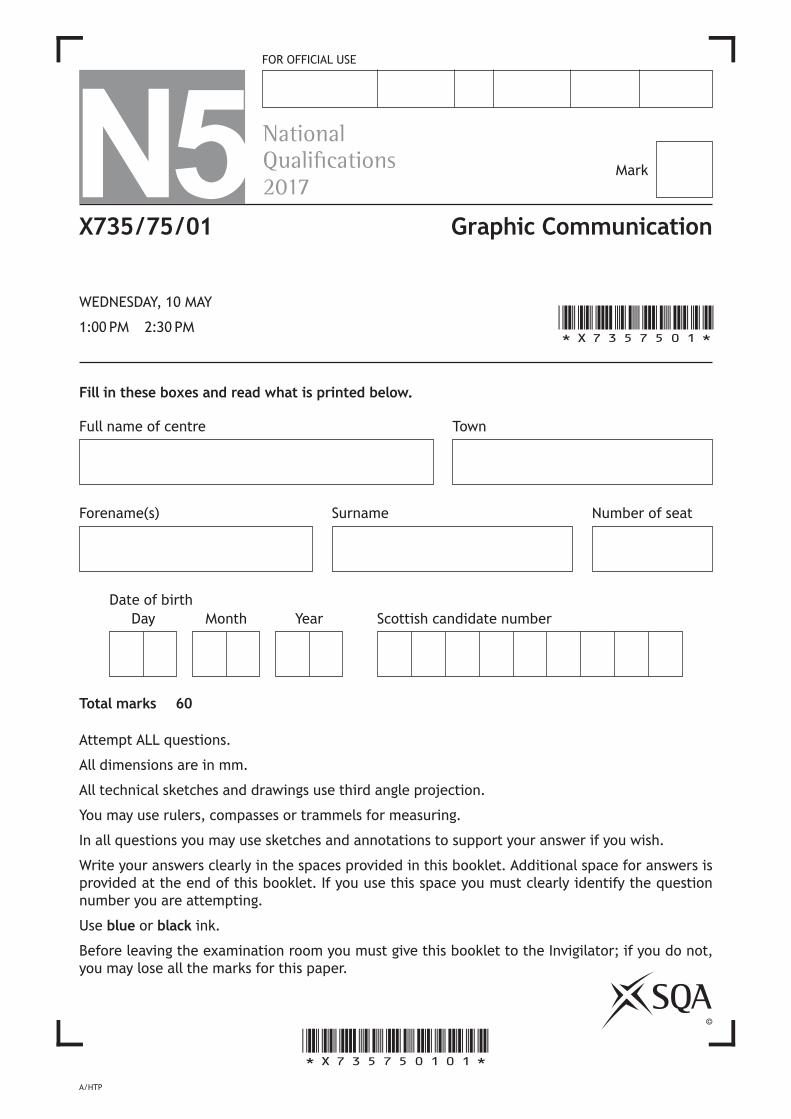
N5FOR OFFICIAL USE
Fill in these boxes and read what is printed below.
Number of seat
Town
©
Mark
Full name of centre
Forename(s) Surname
Scottish candidate numberDate of birth
YearDay Month
NationalQualications2017
Total marks — 60
Attempt ALL questions.
All dimensions are in mm.
All technical sketches and drawings use third angle projection.
You may use rulers, compasses or trammels for measuring.
In all questions you may use sketches and annotations to support your answer if you wish.
Write your answers clearly in the spaces provided in this booklet. Additional space for answers is provided at the end of this booklet. If you use this space you must clearly identify the question number you are attempting.
Use blue or black ink.
Before leaving the examination room you must give this booklet to the Invigilator; if you do not, you may lose all the marks for this paper.
X735/75/01
WEDNESDAY, 10 MAY
1:00 PM – 2:30 PM
A/HTP
Graphic Communication

*X735750102*Page 02
[BLANK PAGE]
DO NOT WRITE ON THIS PAGE
*X735750103*Page 03
MARKS DO NOT WRITE IN
THIS MARGIN
Total marks — 60
Attempt ALL questions
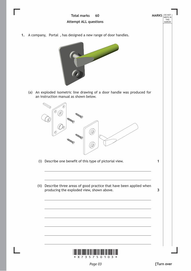
1. A company, “Portal”, has designed a new range of door handles.
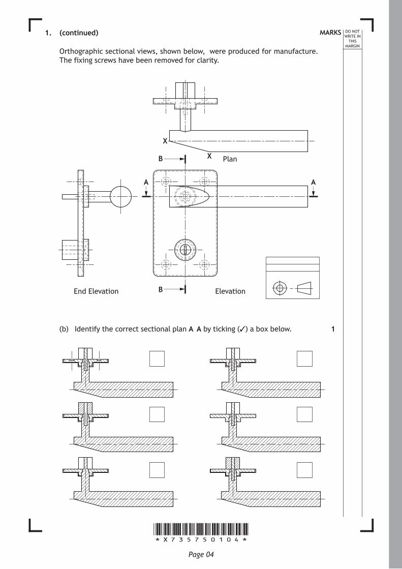
(a) An exploded isometric line drawing of a door handle was produced for an instruction manual as shown below.
(i) Describe one benefit of this type of pictorial view.
(ii) Describe three areas of good practice that have been applied when producing the exploded view, shown above.
1
3
[Turn over
*X735750104*Page 04
MARKS DO NOT WRITE IN
THIS MARGIN
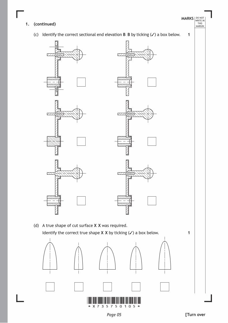
1. (continued)
Orthographic sectional views, shown below, were produced for manufacture. The fixing screws have been removed for clarity.
A A
B
X
X Plan
ElevationEnd Elevation B
(b) Identify the correct sectional plan A–A by ticking (3) a box below. 1
*X735750105*Page 05
MARKS DO NOT WRITE IN
THIS MARGIN
1. (continued)
(c) Identify the correct sectional end elevation B–B by ticking (✓) a box below.
(d) A true shape of cut surface X–X was required.
Identify the correct true shape X–X by ticking (✓) a box below.
1
1
[Turn over

*X735750106*Page 06
MARKS DO NOT WRITE IN
THIS MARGIN
1. (continued)
(e) When producing sectional drawings, different component parts are identified through the use of hatching.
Describe two ways that hatching can be varied to aid the identification of different component parts.
(f) When producing sectional drawings there are certain components and features that are not normally hatched.
State two components or features that are not normally hatched in a sectional view.
2
2
*X735750107*Page 07
[Turn over for next question
DO NOT WRITE ON THIS PAGE
*X735750108*Page 08
DO NOT WRITE IN
THIS MARGIN
1. (continued)
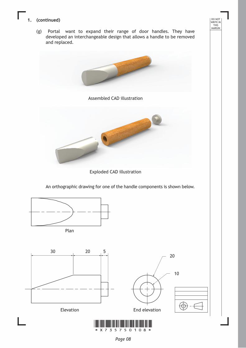
(g) “Portal” want to expand their range of door handles. They have developed an interchangeable design that allows a handle to be removed and replaced.
Assembled CAD illustration
Exploded CAD illustration
An orthographic drawing for one of the handle components is shown below.
Elevation End elevation
Ø20
Ø10
30 20 5
Plan
*X735750109*Page 09
MARKS DO NOT WRITE IN
THIS MARGIN
1. (g) (continued)
Describe, using the correct dimensions and 3D CAD modelling terms, how you would use 3D CAD software to model the handle component in the orthographic drawing, shown opposite. You may use sketches to support your answer. 4
[Turn over
*X735750110*Page 10
DO NOT WRITE IN
THIS MARGIN
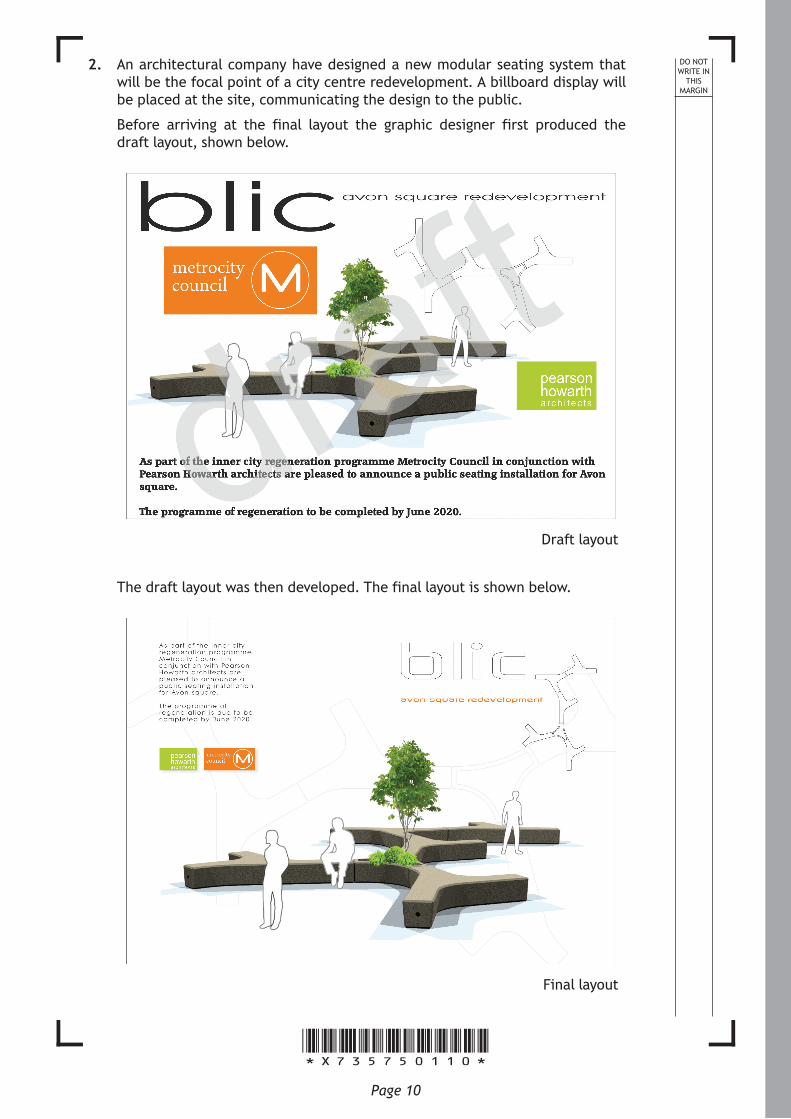
2. An architectural company have designed a new modular seating system that will be the focal point of a city centre redevelopment. A billboard display will be placed at the site, communicating the design to the public.
Before arriving at the final layout the graphic designer first produced the draft layout, shown below.
Draft layout
The draft layout was then developed. The final layout is shown below.
Final layout
*X735750111*Page 11
MARKS DO NOT WRITE IN
THIS MARGIN
2. (continued)
(a) Describe how the graphic designer has applied each of the design elements and principles, listed below, to produce the final layout.
(i) Alignment
(ii) Unity
(iii) Contrast
[Turn over
1
1
1
*X735750112*Page 12
MARKS DO NOT WRITE IN
THIS MARGIN
2. (continued)
(b) The billboard is to be placed on a busy street where pedestrians and traffic will pass by.
Explain how the location of the billboard has influenced the design of the final layout.
(c) When the graphic designer produced the final layout, the following DTP features were used: Grid and Snap to grid.
Describe two ways these DTP features assist the graphic designer.
1
2
*X735750113*Page 13
MARKS DO NOT WRITE IN
THIS MARGIN
2. (continued)
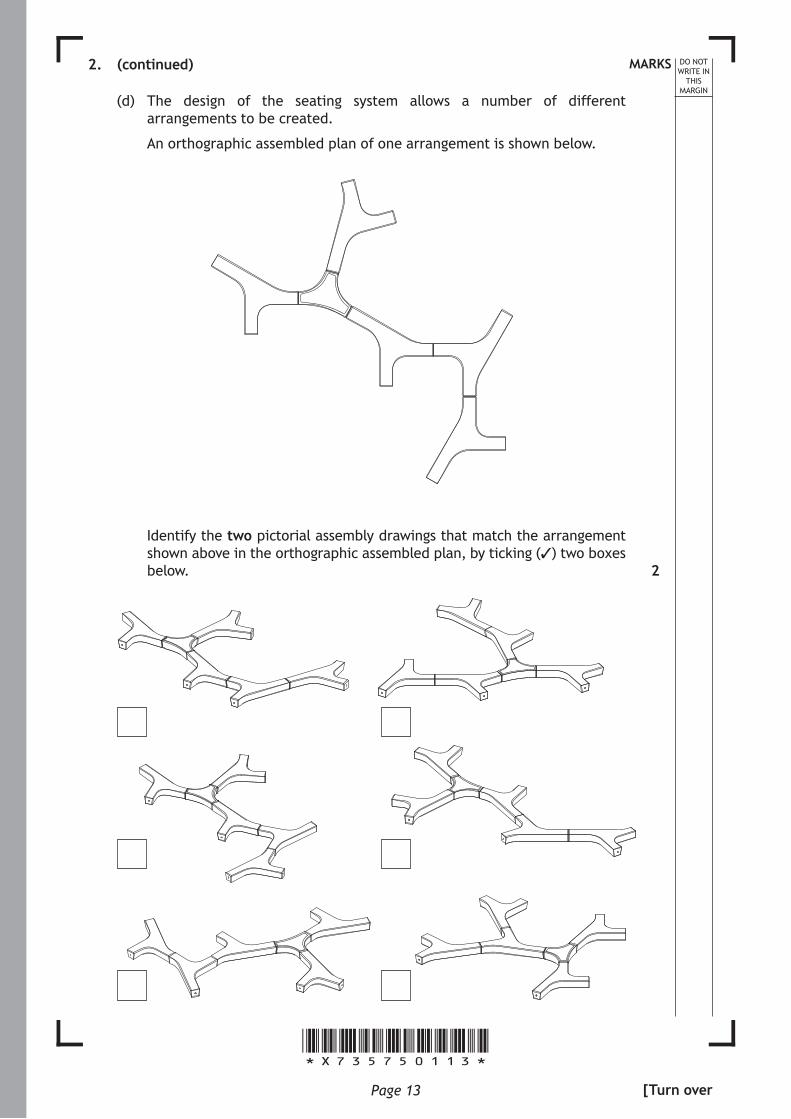
(d) The design of the seating system allows a number of different arrangements to be created.
An orthographic assembled plan of one arrangement is shown below.
Identify the two pictorial assembly drawings that match the arrangement shown above in the orthographic assembled plan, by ticking (✓) two boxes below. 2
[Turn over
*X735750114*Page 14
MARKS DO NOT WRITE IN
THIS MARGIN
2. (continued)
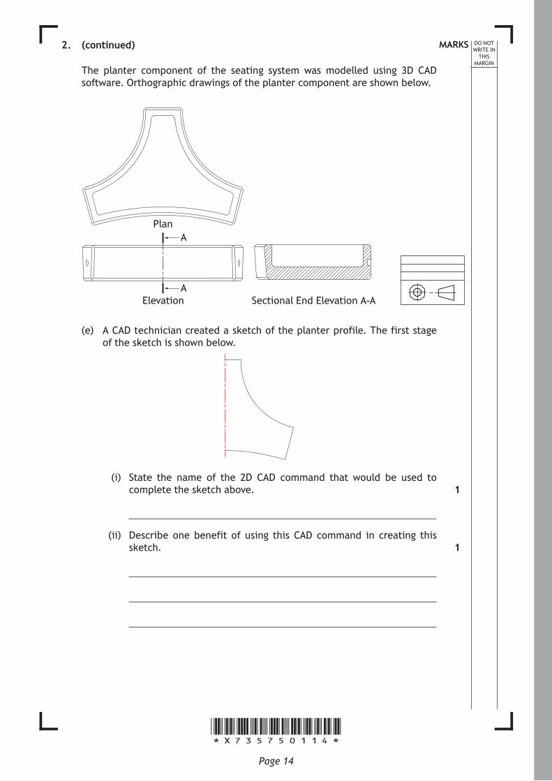
The planter component of the seating system was modelled using 3D CAD software. Orthographic drawings of the planter component are shown below.
PlanA
AElevation Sectional End Elevation A-A
(e) A CAD technician created a sketch of the planter profile. The first stage of the sketch is shown below.
(i) State the name of the 2D CAD command that would be used to complete the sketch above.
(ii) Describe one benefit of using this CAD command in creating this sketch.
1
1
*X735750115*Page 15
MARKS DO NOT WRITE IN
THIS MARGIN
2. (continued)
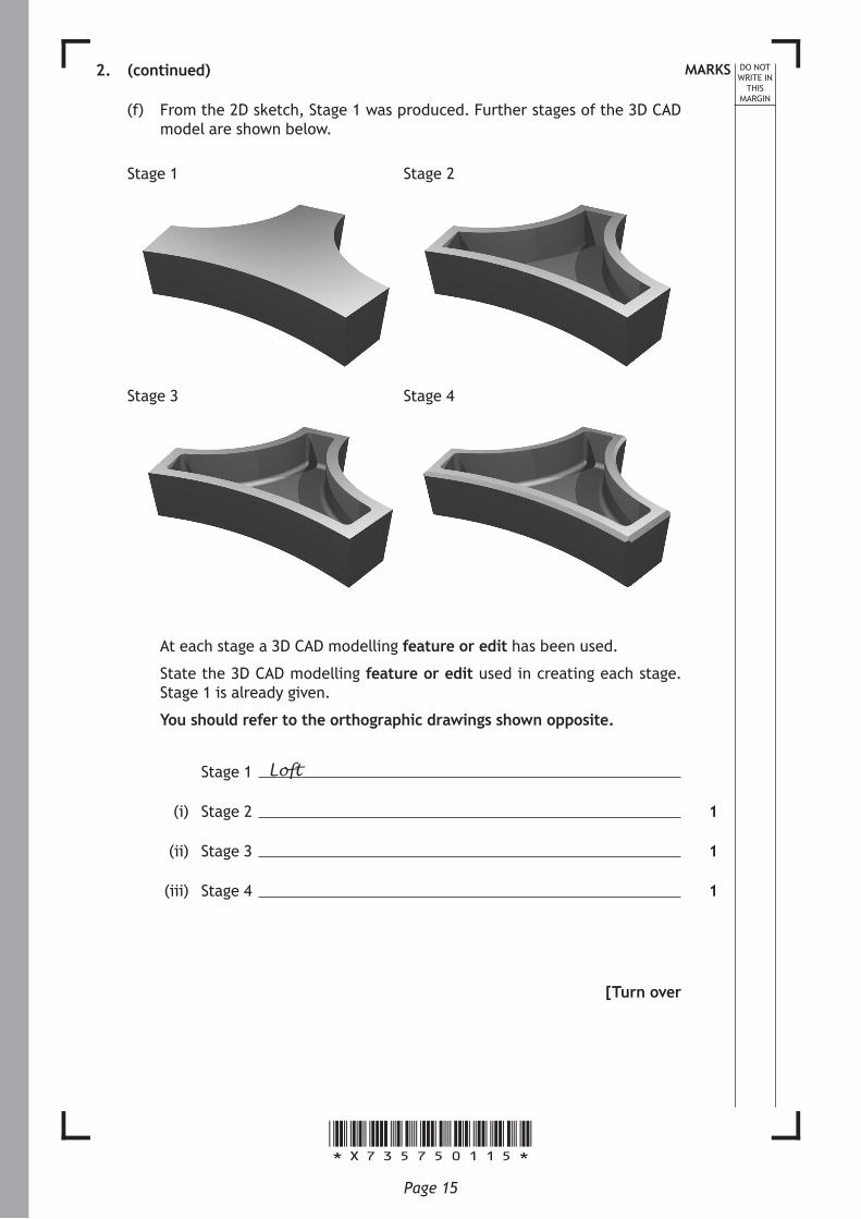
(f) From the 2D sketch, Stage 1 was produced. Further stages of the 3D CAD model are shown below.
Stage 1 Stage 2
Stage 3 Stage 4
At each stage a 3D CAD modelling feature or edit has been used.
State the 3D CAD modelling feature or edit used in creating each stage. Stage 1 is already given.
You should refer to the orthographic drawings shown opposite.
Stage 1 Loft
(i) Stage 2
(ii) Stage 3
(iii) Stage 4
[Turn over
1
1
1
*X735750116*Page 16
MARKS DO NOT WRITE IN
THIS MARGIN
2. (continued)
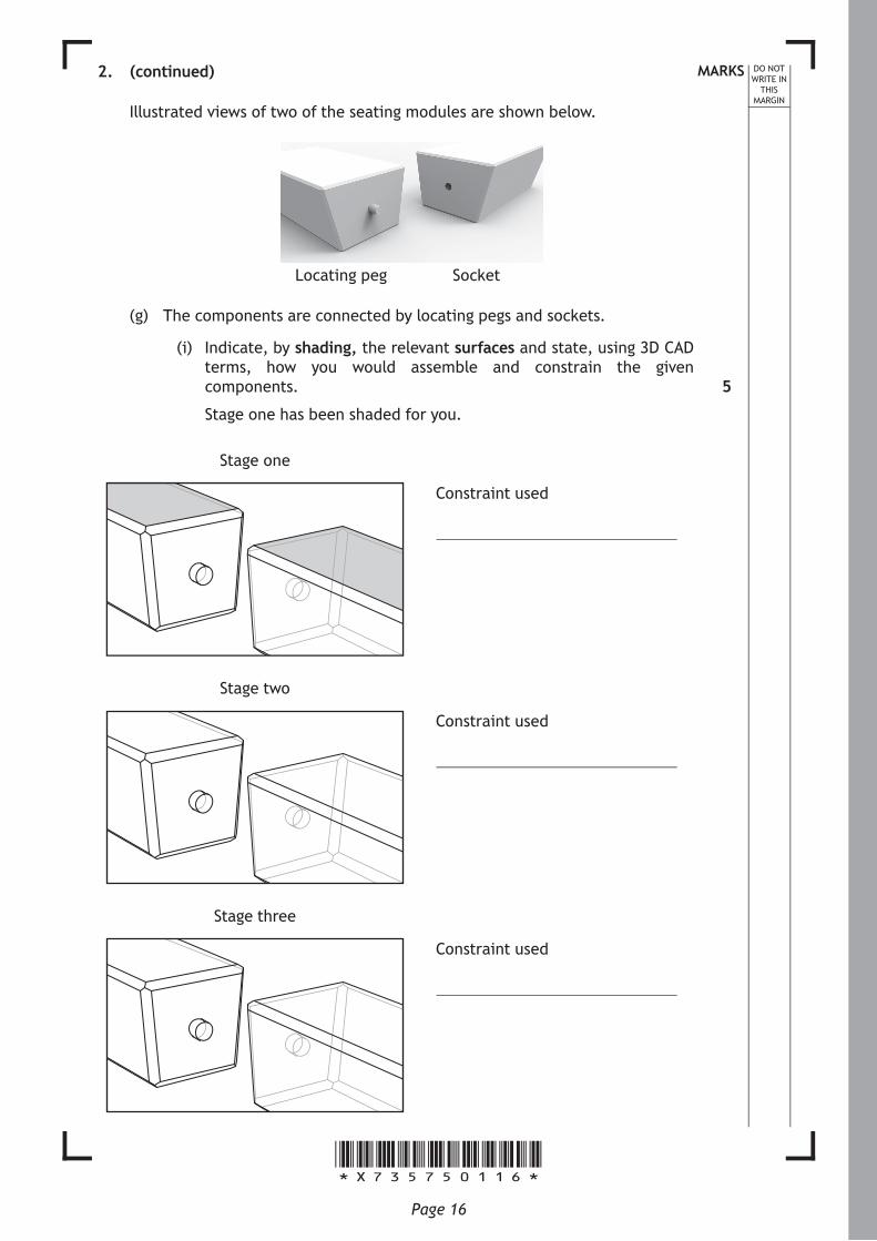
Illustrated views of two of the seating modules are shown below.
Locating peg Socket
(g) The components are connected by locating pegs and sockets.
(i) Indicate, by shading, the relevant surfaces and state, using 3D CAD terms, how you would assemble and constrain the given components.
Stage one has been shaded for you.
Stage one
Constraint used
Stage two
Constraint used
Stage three
Constraint used
5

*X735750117*Page 17
MARKS DO NOT WRITE IN
THIS MARGIN
2. (g) (continued)
The seating system was added to a library of standard components.
(ii) Describe two ways a CAD library can assist the design process.
[Turn over
2
*X735750118*Page 18
MARKS DO NOT WRITE IN
THIS MARGIN
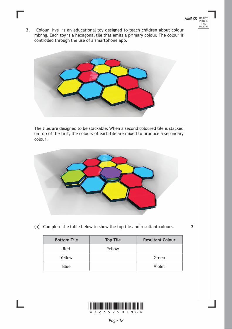
3. “Colour Hive” is an educational toy designed to teach children about colour mixing. Each toy is a hexagonal tile that emits a primary colour. The colour is controlled through the use of a smartphone app.
The tiles are designed to be stackable. When a second coloured tile is stacked on top of the first, the colours of each tile are mixed to produce a secondary colour.
(a) Complete the table below to show the top tile and resultant colours.
Bottom Tile Top Tile Resultant Colour
Red Yellow
Yellow Green
Blue Violet
3
*X735750119*Page 19
MARKS DO NOT WRITE IN
THIS MARGIN
3. (continued)
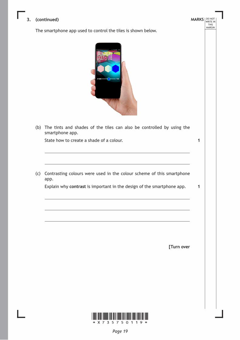
The smartphone app used to control the tiles is shown below.
(b) The tints and shades of the tiles can also be controlled by using the smartphone app.
State how to create a shade of a colour.
(c) Contrasting colours were used in the colour scheme of this smartphone app.
Explain why contrast is important in the design of the smartphone app.
[Turn over
1
1
*X735750120*Page 20
MARKS DO NOT WRITE IN
THIS MARGIN
3. (continued)
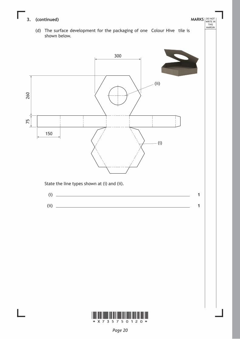
(d) The surface development for the packaging of one “Colour Hive” tile is shown below.
300
260
75
(i)
(ii)
150
State the line types shown at (i) and (ii).
(i)
(ii)
1
1
*X735750121*Page 21
MARKS DO NOT WRITE IN
THIS MARGIN
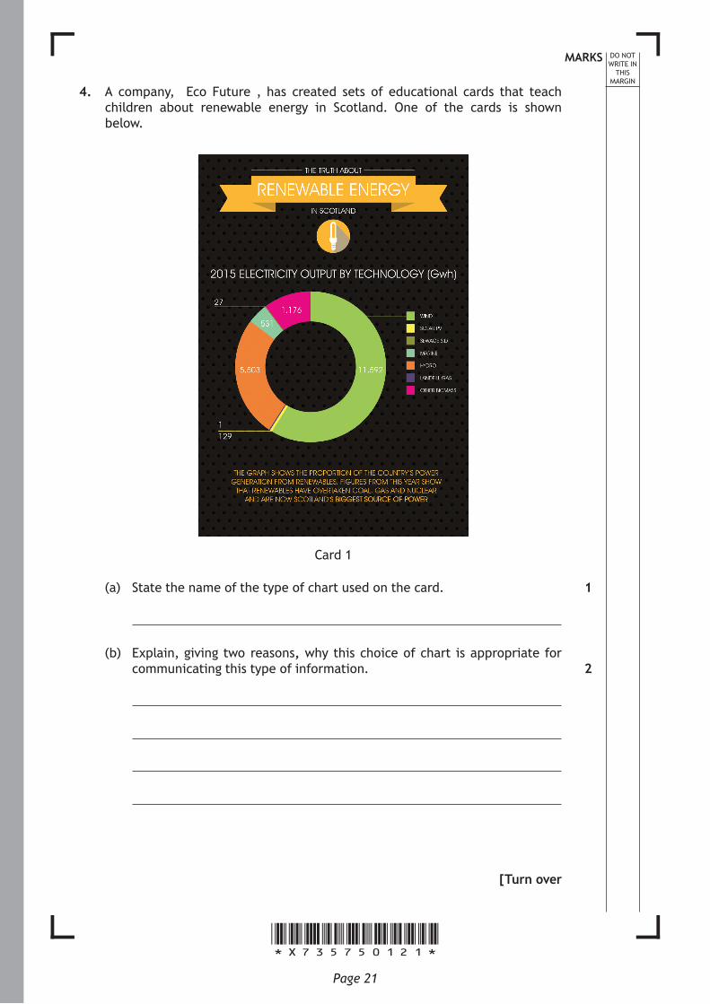
4. A company, “Eco Future”, has created sets of educational cards that teach children about renewable energy in Scotland. One of the cards is shown below.
Card 1
(a) State the name of the type of chart used on the card.
(b) Explain, giving two reasons, why this choice of chart is appropriate for communicating this type of information.
[Turn over
1
2
*X735750122*Page 22
MARKS DO NOT WRITE IN
THIS MARGIN
4. (continued)
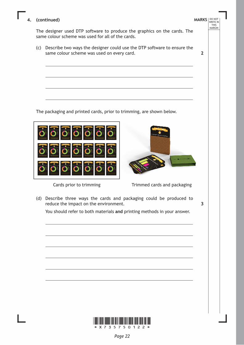
The designer used DTP software to produce the graphics on the cards. The same colour scheme was used for all of the cards.
(c) Describe two ways the designer could use the DTP software to ensure the same colour scheme was used on every card.
The packaging and printed cards, prior to trimming, are shown below.
Cards prior to trimming Trimmed cards and packaging
(d) Describe three ways the cards and packaging could be produced to reduce the impact on the environment.
You should refer to both materials and printing methods in your answer.
2
3
*X735750123*Page 23
MARKS DO NOT WRITE IN
THIS MARGIN
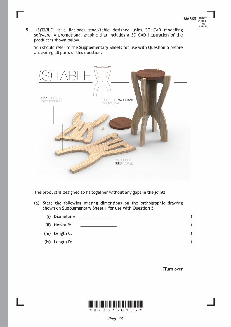
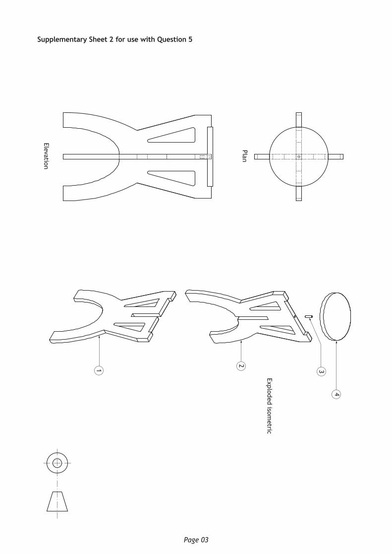
5. “(S)TABLE” is a flat-pack stool/table designed using 3D CAD modelling software. A promotional graphic that includes a 3D CAD illustration of the product is shown below.
You should refer to the Supplementary Sheets for use with Question 5 before answering all parts of this question.
BEAUTIFUL MAHOGANYROUND SEAT
(S)TABLE
OAK LEGS THATSLOT TOGETHER
ONE SINGLEBEECH DOWEL
The product is designed to fit together without any gaps in the joints.
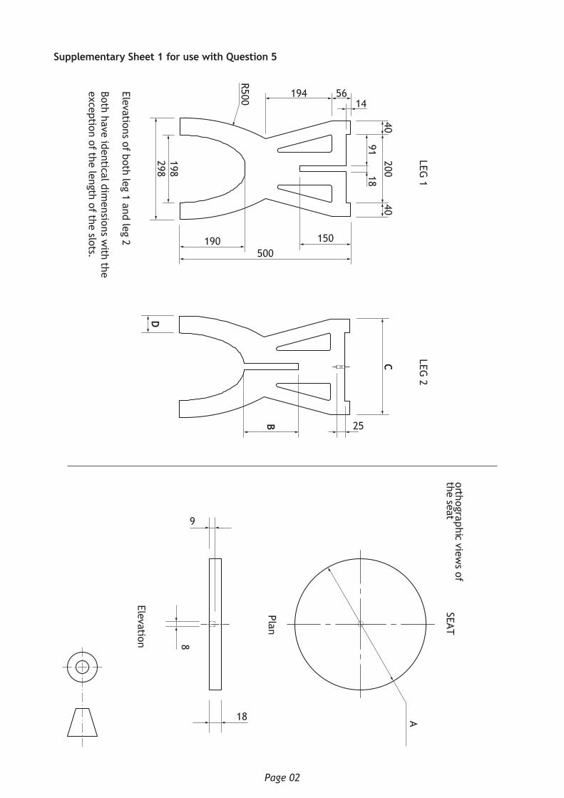
(a) State the following missing dimensions on the orthographic drawing shown on Supplementary Sheet 1 for use with Question 5.
(i) Diameter A:
(ii) Height B:
(iii) Length C:
(iv) Length D:
[Turn over
1
1
1
1
*X735750124*Page 24
MARKS DO NOT WRITE IN
THIS MARGIN
5. (continued)
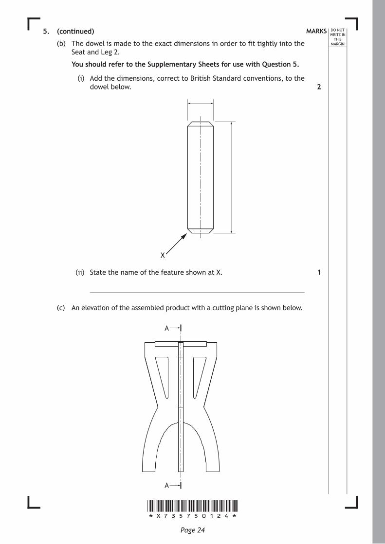
(b) The dowel is made to the exact dimensions in order to fit tightly into the Seat and Leg 2.
You should refer to the Supplementary Sheets for use with Question 5.
(i) Add the dimensions, correct to British Standard conventions, to the dowel below.
X
(ii) State the name of the feature shown at X.
(c) An elevation of the assembled product with a cutting plane is shown below.
A
A
2
1
*X735750125*Page 25
MARKS DO NOT WRITE IN
THIS MARGIN
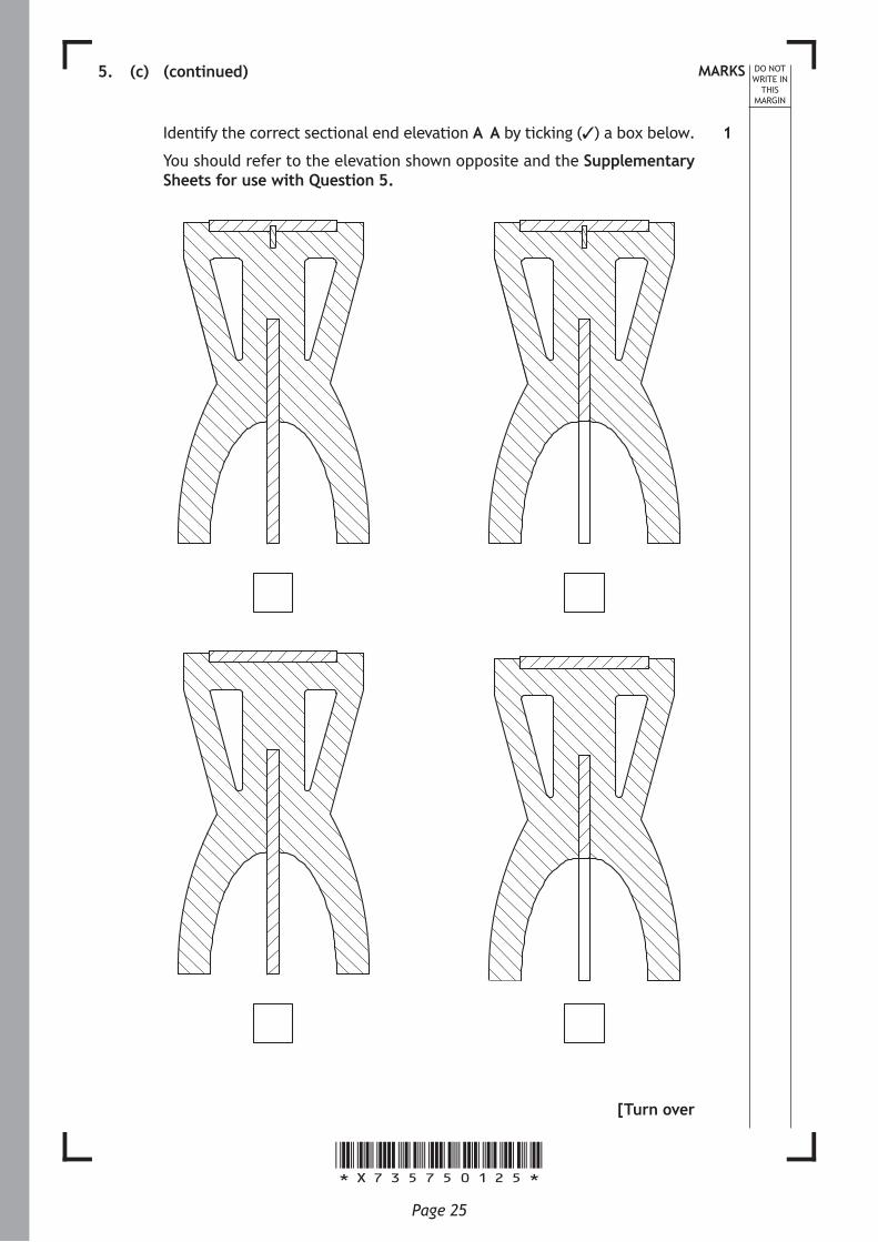
5. (c) (continued)
Identify the correct sectional end elevation A–A by ticking (✓) a box below.
You should refer to the elevation shown opposite and the Supplementary Sheets for use with Question 5.
[Turn over
1
*X735750126*Page 26
MARKS DO NOT WRITE IN
THIS MARGIN
5. (continued)
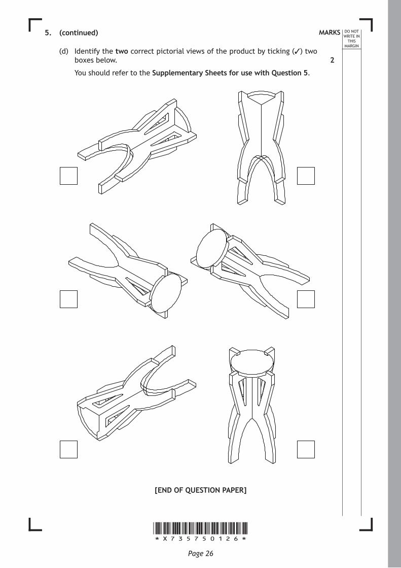
(d) Identify the two correct pictorial views of the product by ticking (✓) two boxes below.
You should refer to the Supplementary Sheets for use with Question 5.
[END OF QUESTION PAPER]
2

*X735750127*Page 27
MARKS DO NOT WRITE IN
THIS MARGIN
ADDITIONAL SPACE FOR ANSWERS
*X735750128*Page 28
MARKS DO NOT WRITE IN
THIS MARGIN
ADDITIONAL SPACE FOR ANSWERS
Acknowledgement of CopyrightQuestion 3(b) Suradech Prapairat/shutterstock.com

*X7357511*
N5
©
NationalQualications2017
Supplementary Sheets for use with Question 5.
X735/75/11 Graphic CommunicationSupplementary Sheets
WEDNESDAY, 10 MAY
1:00 PM – 2:30 PM
A/HTP
Page 02
Supplementary Sheet 1 for use with Question 5
Elevations of both leg 1 and leg 2
Both have identical dimensions w
ith the exception of the length of the slots.
R500
18200
4040
91
198298
190500
150
194 5614
LEG 1
25B
C
D
LEG 2
SEATorthographic view
s ofthe seat
Ø8
Elevation
Plan
9
ØA18
Page 03
Supplementary Sheet 2 for use with Question 5
3
2
4
Plan
1
Exploded isometric
Elevation

Page 04
[BLANK PAGE]
DO NOT WRITE ON THIS PAGE


![National 4XDOLÛFDWLRQV 2017 - SQA · An orthographic CAD drawing of Nozzle 1 is shown below. 30 R47 R1 ... AK PAGE] S PAGE ... 47 176 368 Ø50 Ø9 PARTS LIST ITEM QTY PART NUMBER](https://img.pdfslide.us/doc/110x75/5ac78ed57f8b9a5d718bdefc/national-4xdolfdwlrqv-2017-sqa-orthographic-cad-drawing-of-nozzle-1-is-shown-below.jpg)