Embed Size (px)
Citation preview

NAT L INST. OF STAND & TECH
NIST
PUBUCATtONS
NisrNational Institute of Standards and Technology
Technology Administration, U.S. Department of Commerce
NIST Special Publication 250-67
NIST Time and Frequency Radio Stations
WWV, WWVH, and WWVB
Glenn K. Nelson
Michael A. Lombardi
Dean T. Okayama

rhe National Institute of Standards and Technology was established in 1988 by Congress to "assist industry in the
development of technology ... needed to improve product quality, to modernize manufacturing processes, to ensure
product reliability ... and to facilitate rapid commercialization ... of products based on new scientific discoveries."
NIST, originally founded as the National Bureau of Standards in 1901, works to strengthen U.S. industry's
competitiveness; advance science and engineering; and improve public health, safety, and the environment. One of the
agency's basic functions is to develop, maintain, and retain custody of the national standards of measurement, and provide the
means and methods for comparing standards used in science, engineering, manufacturing, commerce, industry, and education
with the standards adopted or recognized by the Federal Government.
As an agency of the U.S. Commerce Department's Technology Administration, NIST conducts basic and applied
research in the physical sciences and engineering, and develops measurement techniques, test methods, standards, and related
services. The Institute does generic and precompetitive work on new and advanced technologies. NIST's research facilities
are located at Gaithersburg, MD 20899, and at Boulder, CO 80303. Major technical operating units and their principal
activities are listed below. For more information visit the NIST Website at http://www.nist.gov, or contact the Publications
and Program Inquiries Desk, 301-975-3058.
Office of the Director
•National Quality Program
•International and Academic Affairs
Technology Services
•Standards Services
•Technology Partnerships
•Measurement Services
•Information Services
•Weights and Measures
Advanced Technology Program•Economic Assessment
•Information Technology and Applications
•Chemistry and Life Sciences
•Electronics and Photonics Technology
Manufacturing Extension Partnership
Program•Regional Programs
•National Programs
•Program Development
Electronics and Electrical Engineering
Laboratory•Microelectronics
•Law Enforcement Standards
•Electricity
•Semiconductor Electronics
•Radio-Frequency Technology'
•Electromagnetic Technology'
Optoelectronics'
•Magnetic Technology'
Materials Science and Engineering
Laboratory•Intelligent Processing of Materials
•Ceramics
•Materials Reliability'
•Polymers
•Metallurgy
•NIST Center for Neutron Research
Chemical Science and Technology
Laboratory•Biotechnology
•Process Measurements
•Surface and Microanalysis Science
•Physical and Chemical Properties^
•Analytical Chemistry
Physics Laboratory•Electron and Optical Physics
•Atomic Physics
•Optical Technology
•Ionizing Radiation
Time and Frequency'
•Quantum Physics'
Manufacturing Engineering
Laboratory
•Precision Engineering
•Manufacturing Metrology
•Intelligent Systems
•Fabrication Technology
•Manufacturing Systems Integration
Building and Fire Research Laboratory•Applied Economics
•Materials and Construction Research
Building Environment
Fire Research
Information Technology Laboratory•Mathematical and Computational Sciences^
•Advanced Network Technologies
•Computer Security
•Information Access
•Convergent Information Systems
•Information Services and Computing
•Software Diagnostics and Conformance Testing
•Statistical Engineering
'At Boulder, CO 80305Some elements at Boulder, CO

NIST Special Publication 250-67
NIST Time and Frequency Radio Stations:
WWV, WWVH, and WWVB
Glenn K. Nelson
Michael A. Lombardi
Dean T. Okayama
Time and Frequency Division
Physics Laboratory
National Institute ofStandards and Technology
325 Broadway
Boulder, Colorado 80305
January 2005
U.S. Department of Commerce
Carlos M. Gutierrez. Secretary
Technology Administration
Phillip J. Bond, Under Secretaryfor Technology
National Institute of Standards and Technology
Hratch Semerjian, Acting Director

Certain commercial entities, equipment, or materials may be identified in this
document in order to describe a procedure or concept adequately. Such identification
is not intended to imply recommendation or endorsement by the National Institute of
Standards and Technology, nor is it intended to imply that the entities, materials, or
equipment are necessarily the best available for the purpose.
National Institute of Standards and Technology Special Publication 250-67
Natl. Inst. Stand. Technol. Spec. Publ. 250-67, 160 pages (January 2005)
CODEN: NSPUE2
Contents
Contents
Introduction vii
Acknowledgements viii
Chapter 1 . History and Physical Description 1
A. History ofNIST Radio Stations 1
1. History ofWWV 1
2. History ofWWVH 6
3. History ofWWVB 8
B. Physical Description ofNIST Radio Station Facilities 10
1. WWVFaciHties 10
a) WWV and WWVB Land 1
0
b) WWV Buildings 13
c) WWV Transmitters 15
d) WWV Antennas and Transmission Lines 16
e) WWV Back-Up Generator 2
1
f) WWV Time and Frequency Equipment 22
g) Other Equipment (Satellite Systems) 22
2. WWVB Facilities 23
a) WWVB Land 23
b) WWVB Buildings 23
c) WWVB Transmitters 24
d) WWVB Antennas 26
e) WWVB Back-Up Generator 29
f) WWVB Time and Frequency Equipment 30
3. WWVH Facilities 31
a) WWVH Land 31
b) WWVH Buildings 32
c) WWVH Transmitters 33
d) WWVH Antennas 33
e) WWVH Back-Up Generator 35
f) WWVH Time and Frequency Equipment 37
C. Organizational Control ofNIST Radio Stations 38
Chapter 2. Technical Description 39
A. How the NIST Radio Stations Work 39
B. Technical Description ofWWV 40
1 . Timing system 40
2. Broadcast Format 41
///
Remote Frequency Calibrations: The NIST Frequency Measurement and Analysis Service
a) Standard Carrier Frequencies 43
b) Voice Time Announcements 43
c) Standard Time Intervals 44
d) Standard Audio Frequencies 45
e) UTl Corrections 46
f) 100 Hz Time Code 46
g) Official Announcements 48
h) Modulations Levels and Spectrum Allocation 50
i) WWV Signal Monitoring 51
3. Frequencies and Power Levels 52
4. WWV Antennas 54
5. WWV and WWVB Broadcast Monitoring and Alarm Systems 55
6. Commercial Electrical Power Monitoring 58
7. UPS Monitors 58
C. Technical Description ofWWVB 59
1 . Standard Carrier Frequency and Phase Signature 59
2. Time Code and Time Code Generators 59
3. Frequency and Power Level 62
4. Modes of Operation 62
5. Broadcast Control 63
6. RF Switch Matrix 64
7. Control Console 64
8. Automatic Tuning 64
9. Transmitters 64
10. Helix Houses 65
1 1 . Antennas 68
12. Monitoring and Alarm Systems 69
D. Technical Description ofWWVH 70
1 . Timing System 70
2. Broadcast Format 71
a) Standard Carrier Frequencies 72
b) Voice Time Announcements 72
c) Standard Time Intervals 73
d) Standard Audio Frequencies 73
e) UTI Corrections 74
f) 100 Hz Time Code 74
g) Official Announcements 75
h) Modulation Levels and Spectrum Allocation 75
i) WWVH Signal Monitoring 76
3. Frequencies and Power Levels 76
4. WWVH Antennas 77
5. WWVH Broadcast Monitoring and Alarm Systems 79
6. Commercial Electrical Power Monitoring 80
7. UPS Monitors 81
iv
Contents
E. Telephone Time-of-Day Service 81
1. WWV Telephone Time-of-Day Service 81
2. WWVH Telephone Time-of-Day Service 82
Chapter 3. Operational Procedures 83
A. Hardware Maintenance 83
1 . Transmitters and Broadcast Equipment 83
2. Timing Equipment 84
B. Facilities Maintenance 84
C. Scheduled Tasks 85
1. WWV Task Lists 85
2. WWVB Task Lists 87
3. WWVH Task Lists 89
D. Repairs and Service of Equipment 93
1. Facility Service and Repairs at WWV and WWVB 93
2. Facility Service and Repairs at WWVH 93
3. Mission-Specific Service and Repairs at the Radio Stations 94
4. Spare Parts 94
5. Ongoing Tasks 94
E. Failure Modes 95
1. WWV/WWVH Failure Modes 95
a) Timing Failures 95
b) Broadcast Failures 95
c) Other Equipment Failure Modes 96
2. WWVB Failure Modes 97
a) Timing Failures 97
b) Broadcast Failures 97
c) Other Equipment Failure Modes 98
F. Quality Control of Broadcast Information 98
1 . Timing Control 98
2. Frequency Control 99
G. Recordkeeping 99
1 . Operational Recordkeeping 99
2. Equipment Records 100
3. Other Records 101
4. Software 101
5. Data Backup Procedures 101
H. Physical Security 102
1. Physical Security ofWWV and WWVB 102
2. Physical Security ofWWVH 102
Chapter 4. Customers 103
A. Estimated Number of Customers 103
1 . Estimated Number of Customers for WWV/WWVH 1 03
V

Remote Frequency Calibrations: The NIST Frequency Measurement and Analysis Service
2 . Estimated Number of Customers for WWVB 1 04
3. Estimated Num. of Customers for the Telephone Time-of-Day Service 105
B. Coverage Area for Radio Broadcasts 105
1 . Coverage Area for WWV 1 06
2. Coverage Area for WWVH 107
3 . Coverage Area for WWVB 1 09
a) The Effect of Receiver Sensitivity on Coverage Area Size 1 1
1
b) Field Strength Readings (Radial Measurements) 1 1
3
c) Monitoring Field Strength in Near Real-Time 1 1
5
C. How the NIST Radio Stations are Used by their Customers 1 1
5
1. WWV/WWVH Customers 115
a) Time Customers 116
b) Frequency Customers 1 1
8
c) Voice Announcement Customers (Non-Timing) 1 19
2. WWVB Customers 120
a) Time Customers 1 20
b) Frequency Customers 1 2
1
D. Customer Interaction and Support 122
1 . Distribution of Information about the NIST Radio Stations 1 22
a) Web Site 122
b) Publications 122
c) Technical support (e-mail, phone, and postal mail) 124
d) HF Station Voice Announcements 124
Chapter 5. Measurement Uncertainties 125
A. Frequency Uncertainty of Transmitted Radio Signals 125
1 . Transmitted Frequency Uncertainty ofWWV and WWVB 125
a) The Method Used to Control the Station Clock Frequency 1 26
2. Transmitted Frequency Uncertainty ofWWVH 130
B. Time Uncertainty of Transmitted Radio Signals 132
1. Transmitted Time Uncertainty ofWWV and WWVH 133
2. Transmitted Time Uncertainty ofWWVB 134
C. Frequency Uncertainty of Received Radio Signals 137
1 . Received Frequency Uncertainty ofWWV and WWVH 137
2. Received Frequency Uncertainty ofWWVB 138
D. Time Uncertainty of Received Radio Signals 142
1. Received Time Uncertainty ofWWV and WWVH 142
2. Received Time Uncertainty ofWWVB 143
E. Time Uncertainty of Telephone Time-of-Day Service 1 43
F. Summary of Measurement Uncertainties 145
G. Establishing Traceability to UTC(NIST) 146
References 147

Introduction
Introduction
The National Institute of Standards and Technology (NIST) provides standard time and
frequency information through three radio broadcast stations that are routinely used by
millions of customers. The stations, WWV and WWVB, located near Fort Collins, Colorado,
and WWVH, located on the island of Kauai in Hawaii, are the only radio stations located in the
United States whose sole purposes are to distribute standard time and frequency information.
This document was written in support of the NIST quaUty system. It provides a
comprehensive look at the NIST time and frequency radio stations. It provides a physical and
technical description of each station, and describes how the stations are operated by NIST. It
also examines how the stations are used by their customers, and estimates the measurement
uncertainties of the radio signals, both as transmitted by NIST and as received by customers.
V//
NIST Time and Frequency Radio Stations: WWV, WWVH, and WWVB
Acknowledgements
The authors thank and acknowledge the radio station staff members who help perform the tasks
described in these pages, and who contributed to the information contained in this document,
including: Matt Deutch, Douglas Sutton, Bill Yates, and Judy Folley of WWVAVWVB, and
Edward Pagaduan, Dean Takamatsu, Adele Ochinang, and Don Patterson (now retired from
NIST) ofWWVH. We also thank the current and former Time and Frequency Services group
leaders, John Lowe and Wayne Hanson (now retired from NIST), for their editorial review of
the document; Victor Zhang ofNIST for his work with the common-view GPS systems used to
synchronize the station clocks to UTC(NIST); and Andrew Novick of NIST, who provided the
cover art and several of the technical illustrations. And finally, a special thank you is due to
Peder Hansen of the Space and Naval Warfare Systems Center, who has made large
contributions to the current design of WWVB, and whose technical reports proved to be
extremely valuable to the authors while creating this document.

Chapter 1 - History and Physical Description
Chapter 1
History and Physical Description
This chapter includes the history of NIST radio stations WWV, WWVB, and WWVB, and
then provides a complete physical description of each station's facilities. It also describes the
organizational control of the NIST radio stations.
A. History of NIST Radio Stations
1. History ofWWVWWV has a long and storied history that dates back to the early days of radio broadcasting. The
National Institute of Standards and Technology (NIST) has been involved with radio and radio
frequency research almost from its founding in 1901. Scientists at the National Bureau of
Standards (NBS), as it was then known, began research in radio frequency propagation as early
as 1905. During World War I, NBS had established its Radio Section, which worked closely
with the military to research and develop radio techniques for defense and navigation.
The radio station call letters WWV were assigned to NBS in October 1919. Although the call
letters WWV are now synonymous with the broadcasting of time signals, it is unknown whythose particular call letters were chosen or assigned. Testing of the station began from
Washington, D.C. in May 1920, with the broadcast of Friday evening music concerts that lasted
from 8:30 to 1 1:00 p.m. The 50 W fransmissions used a wavelength of 500 m (about 600 kHz,
or near the low end of today's commercial AM band), and could be heard about 40 km away
from the station. A news release dated May 28, 1920 hinted at the significance of this event:
This means that music can be performed at any place, radiated into the air by
means of an ordinary radio set, and received at any other place even though
hundreds ofmiles away. The music received can be made as loud as desired by
suitable operation ofthe receiving apparatus. Such concerts are sometimes sent
out by the radio laboratory ofthe Bureau ofStandards in connection with trials
of experimental apparatus. This music can be heard by anyone in the states
near the District of Columbia having a simple amateur receiving outfit. The
pleasant evenings which have been experienced by persons at a number ofsuch
receiving stations suggest interesting possibilities of the future [1].
These early experimental musical broadcasts preceded all commercial broadcast stations by
about six months. KDKA of Pittsburgh, Pennsylvania, generally acknowledged as the first
commercial broadcast station, did not go on the air until November 2, 1920.
On December 15, 1920, WWV began assisting the Department of Agriculture in the distribution
of market news to farm bureaus and agricultural organizations. A 2 kW spark transmitter and
1

NIST Time and Frequency Radio Stations: WWV, WWVH, and WWVB
telegraphic code was used to broadcast 500-word reports, called the Daily Market Marketgram,
on 750 kHz. The operating radius was about 300 km out of Washington. These broadcasts
continued until April 15, 1921.
By December 1922, it was decided that the station's purpose would be the transmission of
standard frequency signals, as a reference standard for other radio broadcasters. The first tests of
WWV as a standard frequency station were conducted on January 29-30 of 1923, and included
the broadcast of frequencies from 200 to 545 kHz [1]. By March of 1923 [2], WWV was
broadcasting frequencies from 125 to 2000 kHz on a monthly or weekly schedule. The accuracy
of the transmitted frequency was quoted as being "better than three-tenths of one per cent." The
output power of the station was now 1 kW [3].
During the early days of the WWV broadcasts, the fransmitter was adjusted to the correct
frequency using a working standard wavemeter, which had earlier been checked against the
national standard wavemeter [4, 5]. The first quartz oscillators were developed shortly before
WWV went on the air, and soon replaced the wavemeter as a national standard of frequency. For
a short time, a working standard wavemeter was calibrated against a quartz oscillator, and then
used to adjust the transmitter, but by 1927 a 50 kHz temperature-controlled quartz oscillator was
located at the station site and used as a standard. During the transmission, the frequency of the
transmitter was held manually so that no beat note was audible between the transmitter and the
standard oscillator.
The quartz oscillator made it possible for WWV to meet the needs of the radio industry, which
desperately needed a reliable reference standard for frequency. The number of radio stations was
rapidly increasing across the United States, and it was essential for all stations to stay near their
assigned frequencies so that stations would not interfere with each other, keeping the airwaves
usable. By 1928, the Federal Radio Commission was calling for all stations to stay within 500
Hz of their assigned frequency. This prompted J. H. Dellinger, then chief of the Radio Section of
NBS, to write:
While an accuracy ofone-halfpercent was satisfactory five years ago, it is nownecessary to give consideration to accuracies a thousand times as good. It is not
merely a question of measurement. Frequencies of transmitting stations must
actually be held constant with very great accuracy. This is becoming more andmore important as the available radio channels become saturated. The
maximum number of communications can be packed into the radio spectrum
only if each stays within its own channel, as any wandering due to inaccurate
frequency adjustment causes interference with communication on the adjacent
channel [6].
WWV was able to respond to the needs of the radio industry as improvements in quartz oscillator
technology and improved measurement techniques made the transmitted uncertainty of WWVdecrease from parts per thousand to parts per million by 1931. However, WWV also faced the
problem of an inability to cover the entire United States, since for the most part its signals did not
2
Chapter I - History and Physical Description
reach the area west of the Mississippi. To address this problem, a Hst of other broadcast stations
found to be suitable as frequency references was maintained. The fi-equencies of these stations
were measured by NBS, and the list was published monthly in the Radio Service Bulletin. NBSalso sponsored and helped control other standard frequency broadcasts. Stanford University's
radio station 6XBM transmitted standard frequencies for the west coast from September 1 924 to
June 1926 [7], and frequencies of value to radio amateurs were sent from station IXM of the
Massachusetts Institute of Technology, and station 9XL of the Gold Medal Flour Company in
Minneapolis, Minnesota.
Since other stations were available as frequency references, an announcement was made in 1926
that WWV might be turned off [8]. However, many commercial, government, and private users
responded, asking that the WWV broadcasts be continued and improved. Standard frequency
broadcasts were discontinued at 6XBM, but work began at WWV to use a quartz oscillator to
directly control the transmitter, rather than using the manual zero beat technique of the past. It
was decided that only one frequency, 5 MHz, would be broadcast using this new approach.
Broadcasts on 5 MHz, controlled by quartz oscillators and accurate to parts in 10*', began from
College Park, Maryland in January 1931 from a new 150 W fransmitter. The 5 MHz frequency
was chosen for several reasons, including "its usual lack of skip distance and comparatively wide
coverage, its relative freedom from previously assigned stations, and its convenient integral
relation with most frequency standards" [9]. The transmission schedule varied, but for a time it
was every Tuesday for two hours in the morning and two hours at night [10]. Within a year, the
power was increased to 1 kW and the uncertainty was reduced to less than 1 part in 10^ [11].
Until September 1931, less accurate broadcasts were made once per month on other frequencies.
By 1932, it was clear that the station had become part of the national infrastructure, and so work
began on making the signals accessible to more Americans, by relocating the station and
designing new transmitters and antennas in order to increase the coverage area. The station was
moved in December 1932 to a Department of Agriculture site near Beltsville, Maryland. ByApril 1933, the station was broadcasting 30 kW at 5 MHz, and 10 and 15 MHz broadcasts (at 20
kW output power) were added in 1935. The 10 and 15 MHz frequencies were chosen as
harmonics or multiples of 5 MHz. By this time, the station frequency was controlled to within
about 2 parts in 10* [9]. In June 1937, standard musical pitch (A440), second pulses, standard
time intervals, and ionosphere bulletins were added to the broadcast. The 1 5 MHz carrier was
replaced by a 20 MHz transmission, although 15 MHz was restored in May 1940.
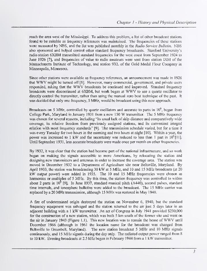
A fire of undetermined origin destroyed the station on November 6, 1940, but the standard
frequency equipment was salvaged and the station returned to the air just 5 days later in an
adjacent building with a 1 kW transmitter. An act of Congress in July 1941 provided $230,000
for the construction of a new station, which was built 5 km south of the former site and went on
the air in January 1943 (Figure 1.1). This new location was to remain the home ofWWV until
December 1966 (although in 1961 the location name for the broadcast was changed from
Beltsville to Greenbelt, Maryland). The new station broadcast 5 MHz and 10 MHz signals
continuously, and 1 5 MHz signals during the day only. The radiated output power ranged from 8
to 10 kW. Evening broadcasts at 2.5 kHz began in February 1944 from a 1 kW transmitter.
3

NIST Time and Frequency Radio Stations: WWV, WWVH, and WWVB
Figure 1.1. Station WWV in Beltsville, Maryland.
By now well established as a reference source for frequency and time interval, WWV was still
not used as a time synchronization source. The standard time interval markers broadcast by the
station were not in phase with any reference source. This changed in June 1944, when the
Superintendent of the United States Naval Observatory (USNO) authorized the synchronization
of the WWV time signals with those of the USNO. In October 1945, the station added time
announcements (Eastern Standard Time) in telegraphic code, given every 5 minutes. In
December 1946, four new carrier frequencies were added: 20, 25, 30, and 35 MHz. The station
was now broadcasting continuously on seven different frequencies, both day and night, and from
9 p.m. to 7 a.m. on 2.5 MHz [12].
Voice announcements of time, probably WWV's best known feature, began on January 1, 1950,.
helping to usher in the second half of the twentieth century. The voice announcements were
given every 5 minutes. Standard frequencies of 600 and 440 Hz were broadcast during
alternating minutes. The 30 and 35 MHz broadcasts were discontinued in January 1953, and the
25 MHz broadcast was stopped in 1977. With the exception of an almost two-year interruption in
1977 and 1978, the 20 MHz broadcasts have continued to the present day. Geophysical alert
messages began in July 1957. And as quartz oscillator technology improved, so did the
4
Chapter 1 - History and Physical Description
frequency control of the broadcast. By 1958, the transmitted frequency was routinely kept within
2 parts in lO'^of the national standard.
From 1955 to 1958, WWV played a key role in the definition of the atomic second. During this
period the United States Naval Observatory (USNO) in Washington, D.C. and the National
Physical Laboratory (NPL) in Teddington, United Kingdom made simultaneous common-viewmeasurements of the signals broadcast from WWV. The USNO compared the signal to an
astronomical time scale (UT2), and NPL compared the signal to the new cesium standard they
had just developed. The data they collected helped the USNO and NPL equate the length of the
asfronomical second to the atomic second, and led to the atomic second being later defined as the
duration of 9,192,631,770 cycles of the cesium atom [13].
An experimental time code containing year, month, day, and precise time-of-day began in April
1960 [14] and was made part of the regular broadcast in January 1961 [15]. This time code,
knowTi as the NASA 36-bit code, was produced at a 100 Hz rate using 1000 Hz modulation.
Believed to be the first digital time code broadcast in the United States, it made it possible for the
first time for self-setting, radio controlled clocks to appear. Earlier radio controlled clocks
required human interaction to initially synchronize. The current time code format (modified
slightly over the years) was a modified version of the IRIG-H code format. It was initiated on
July 1, 1971 using a 1 Hz rate and 100 Hz modulation. The new code included a daylight saving
time (DST) indicator [16]. The telegraphic time code was also permanentiy removed on this
date.
In 1966, WWV was moved to its current location, near Fort Collins, Colorado [17]. The LFstation WWVB had gone on the air in July 1963 near Fort Collins, and it was decided that WWVwould share the same 390 acre (158 hectare) site. On December 1, 1966 at 0000 UTC, the station
in Greenbelt, Maryland went off the air, and the new station simultaneously went on the air in
Fort Collins.
The current site is about 80 km from the Boulder laboratories where the national standards of
time and frequency are kept. The proximity to Boulder and the use of atomic oscillators at the
transmitter site originally made it possible to control the fransmitted frequency to within 2 parts in
lO", a factor of 10 improvement. Today, the station's frequency is confrolled to within a few
parts in lO'l
In April 1967, WWV began broadcasting Greenwich Mean Time (GMT) instead of local time,
and began its current format of using Coordinated Universal Time (UTC) in January 1974. The
time announcements were now made every minute, instead of every 5 minutes, beginning on July
1, 1971, the same date when the current form of the digital time code was added. The station
broadcast the first "leap second" in history in June 1972.
On August 13, 1991 WWV began broadcasting voice recordings that were digitized and stored in
solid state memory devices. Previous voice recordings had been played back from mechanical
drum recorders, which were more prone to failure. The change in equipment required the voice
of the announcer to be changed. Don Elliot Heald is believed to have been the original voice of
5

NIST Time and Frequency Radio Stations: WWV, WWVH, and WWVB
WWV when announcements of time began in 1950 [18]. His voice was used until August 13,
1991, when the voice equipment was changed. For a short time, the voice of John Doyle was
used for the time announcements. However, the station received a number of complaints that
Mr. Doyle's voice was significantly different from Mr. Elliott's, a voice that had been
associated with timekeeping for some forty years. As a result, the voice was changed to that of
Lee Rodgers, who remains the current announcer. Mr. Rodgers voice was chosen since it was
"close" to the voice of Mr. Elliott, and WWV's many listeners seemed to be happy with the
change.
The station has undergone a number of equipment and maintenance changes in recent years, but
the broadcast format of the station has remained essentially unchanged since 1991, when year
information was added to the time code, and the DST notification included in the time code was
improved.
2. History of WWVHWWVH began operation on November 22, 1948 at Kihei on the island of Maui, in the then
territory of Hawaii (Hawaii was not granted statehood until 1959). A meeting of the
International Telecommunications Union (ITU) held in 1947 resulted in agreements that
standard frequency stations would be allocated 2.5, 5, 10, 15, 20, and 25 MHz, frequencies
already used by WWV. NBS then made the decision to build WWVH as a second standard
frequency station to be operated simultaneously with WWV. The second station would
increase the service coverage area, would allow NBS to determine the amount of accuracy
obtainable in synchronizing two or more standard frequency stations, and would also allow
NBS to develop methods for operating separate stations on the same frequency. The Hawaii
location was chosen to maximize the coverage area and to prevent interference to existing users
ofWWV services [19].
The original WWVH station broadcast a signal of about 1 kW on 5, 10, and 15 MHz. The
station was turned off twice daily, at 0700 and 1 900 GMT, to permit reception of WWV. The
path delay between WWV (then located in Beltsville, Maryland) and WWVH was about 27 ms,
and the WWV signals were used to help calibrate the WWVH broadcast [19].
The station's frequency was controlled to within 5 parts in 10^ by 1956 [20]. The radiated
output power on 5, 10, and 15 MHz was 2 kW, and as it does today, the program schedule of
WWVH closely followed the format of WWV [21]. However, voice announcements of time
were not added to the WWVH broadcast until July 1964, some 14 years after they first
appeared on WWV. The original voice announcements broadcast Hawaiian Standard Time,
and occurred in the first half of every fifth minute during the hour [22]. A 1 kW, 2.5 MHzbroadcast began in 1965.
The original WWVH station site (Figure 1.2) was being constantly threatened by an eroding
shoreline, and much of the station's equipment and property had been damaged. It was
estimated that 75 ft of shoreline were lost in the period from 1949 to 1967. By 1965, the ocean
was within a few meters of both the main building and the 1 5 MHz antenna, and it was
obviously necessary to move WWVH to a new location.
6

Chapter 1 - History and Physical Description
Figure 1.2. The original WWVH station site in Maui.
A congressional appropriation in June 1968 was used to fund the new station. On July 1, 1971,
the station began broadcasting from its current location, a 30 acre (12 hectare) site near Kekaha
on the Island of Kauai, Hawaii. This site is located on a United States Naval base called the
Pacific Missile Range Facility (PMRP).
Many changes took place when the station moved to Kauai. The ERP was increased to 10 kWon 5, 10, and 15 MHz, and 2.5 kW (increased to 5 kW shortly afterwards) on 2.5 MHz. A new2.5 kW 20 MHz broadcast was added (but later turned off in February 1977). Voice
announcements began every minute, and a woman's voice, that of Ms. Jane Barbe, was used
for the announcements. Also, the station began transmitting a digital time code for the first
time, and the telegraphic time code was discontinued [23, 24]. The station was now offering
services nearly identical to those provided by WWV.
In August 1991, both WWV and WWVH began broadcasting voice recordings that were
digitized and stored in solid state memory devices. The voice ofJane Barbe was still used for the
announcements, but the digital storage device made her voice sound slightly different.
7

NIST Time and Frequency Radio Stations: WWV, WWVH, and WWVB
Hurricanes have harmed WWVH on at least two occasions. In 1982, Kauai was struck by
Hurricane Iwa and the station remained on emergency power for seven days. In 1992, Hurricane
Iniki passed over the station, damaging the roof, interior, antennas, and fences, as well as cutting
power and communications and blocking roads. For a few days, only the 5 MHz transmitter
remained on the air (at halfpower), but other station services were quickly restored.
Like WWV, the station has undergone a number of equipment and maintenance changes in recent
years, but the broadcast format has remained essentially unchanged since 1991, when year
information was added to the time code, and the DST notification in the time code was improved.
3. History of WWVBWWVB began operation as radio station KK2XEI in July 1956. This experimental station was
operated from 1530 to 2000 hours universal time each working day from Boulder, Colorado.
The continuous wave 60 kHz signal was not modulated, except for a call sign ID that was sent
every 20 minutes. The effective radiated power (ERP) was originally said to be 40 W [24], but
later reduced to 1.4 W. Data recorded in January 1957 showed that the frequency of the
broadcast was within a few parts in lO'^ of the national standard located in the adjacent
Boulder laboratory, proving (as expected) that a LF transmission was far more stable than the
signals from WWV and WWVH [25, 26].
The success of the 60 kHz broadcast led to the construction of a very low frequency (VLF)
radio station named WWVL, which began operation from Sunset, Colorado in April 1960
using a carrier frequency of 20 kHz. It was originally planned to use the 20 kHz for worldwide
coverage, and the 60 kHz broadcast for coverage of the United States [27]. In March 1960
[28], the call sign WWVB was obtained by NBS for the 60 kHz station. The "B" in the call
sign probably stands for Boulder, the site of the original transmitter. However, one interesting
theory is that the "B" could stand for Brown. W. W. Brown, one of the designers of the Fort
Collins station, was employed as a contractor by NBS when the call sign application was
submitted. Perhaps not coincidentally, his initials were W. W. B.
In 1962, NBS began building a new facility on a site north of Fort Collins, Colorado that would
later also become the home ofWWV. The site was attractive for several reasons, one being its
exceptionally high ground conductivity, which was due to the high alkalinity of the soil. It was
also reasonably close to Boulder (about 80 km, 49.3 mi), which made it easy to staff and
manage, but much farther away from the mountains. The increased distance from the
mountains made it a better choice for broadcasting an omni-directional signal.
WWVB went on the air on July 5, 1963, broadcasting a 5 kW signal on 60 kHz. This was later
increased to 7 kW and then 13 kW, where it remained until December 1997. WWVL began
transmitting a 500 W signal (later increased to 2 kW) on 20 kHz the following month. WWVLhad a relatively short life span, going off the air in July 1972, but WWVB went on to become a
permanent part of the nation's infrastructure [29, 30, 31].
A time code was added to WWVB on July 1, 1965 [32]. This made it possible for radio clocks
to be designed that could decode the signal, recover the time, and automatically set themselves.
8

Chapter 1 - History and Physical Description
The time code format has changed only sHghtly since 1965; it uses a scheme known as binary
coded decimal (BCD), which uses four binary digits (bits) to send one decimal number.
The WWVB broadcast continued operations up to the 1990's with only minor modification to
the format or equipment. The number of customers was relatively small, mostly calibration
laboratories who operated WWVB disciplined oscillators, devices that utilized the 60 kHzcarrier as a frequency reference. Also, the limitations of the aging transmitting equipment at
WWVB became increasingly apparent as the years passed. The situation came to a head on
February 7, 1994 when a heavy mist froze to the antenna, and the antenna tuning system could
not compensate, shutting down the WWVB broadcasts for about 30 hours [33]. After
reviewing the available options, it was decided that a redesign of the entire WWVBtransmitting system was necessary.
During the discussions about redesigning WWVB, it was decided to substantially raise the
power level of the broadcasts. It was obvious that WWVB could play a much larger role and
reach far more customers if the signal were easier to receive. In Europe, low cost radio
controlled clocks were beginning to appear, designed to synchronize to stations such as MSF in
the United Kingdom and DCF77 in Germany. These stations were very similar to WWVB, but
had a much smaller coverage area to service. As a result, European customers were able to
purchase radio controlled alarm clocks, wall clocks, and wristwatches at reasonable prices.
These products lacked the external antennas and high sensitivity of the laboratory receivers, but
would undoubtedly work well in the United States if the WWVB signals were made stronger.
Expert consultants and engineers from the U.S. Navy's LF/VLF support group were hired by
NIST beginning in October 1994 to evaluate the WWVB system and propose changes. Their
reports suggested that although the antennas themselves were in reasonably good shape, the
transmitters and matching equipment should be completely redesigned and new or upgraded
equipment installed. The project progressed in phases over the next several years, as funding
and equipment became available. Discussions between agencies at the highest levels resulted
in the transfer of modem LF transmitters and other equipment from recently decommissioned
Navy facilities to NIST. New station staff members were hired who had previous experience
with the new systems and equipment. Contractors normally employed by the Navy for LFwork were hired to design a new broadcast control system fully utilizing the assets of the
existing station.
A formal announcement that the WWVB power was to be increased was made during 1996,
and a significant number of low cost radio controlled clock products were introduced in the
United States shortly after the announcement. By December 1997, an interim stage of the
upgrade was completed and the ERP was increased to about 25 kW. By August 5, 1999, the
upgrade was complete. The new WWVB configuration used two modem transmitters
operating into two antennas that simultaneously broadcast the same 60 kHz signal. This
increased the ERP to 50 kW, about four times more power than the pre-upgrade configuration
[33]. The increase in power greatly increased the coverage area, and low cost radio controlled
clocks that synchronized to WWVB soon became commonplace throughout the United States.
9
NIST Time and Frequency Radio Stations: WWV, WWVH, and WWVB
B. Physical Description of NIST Radio Station Facilities
This section contains a physical description of the NIST radio station facilities, including the
buildings and equipment located at each site. A technical description ofhow each radio station
works is provided in Chapter 2.
1. WWV Facilities
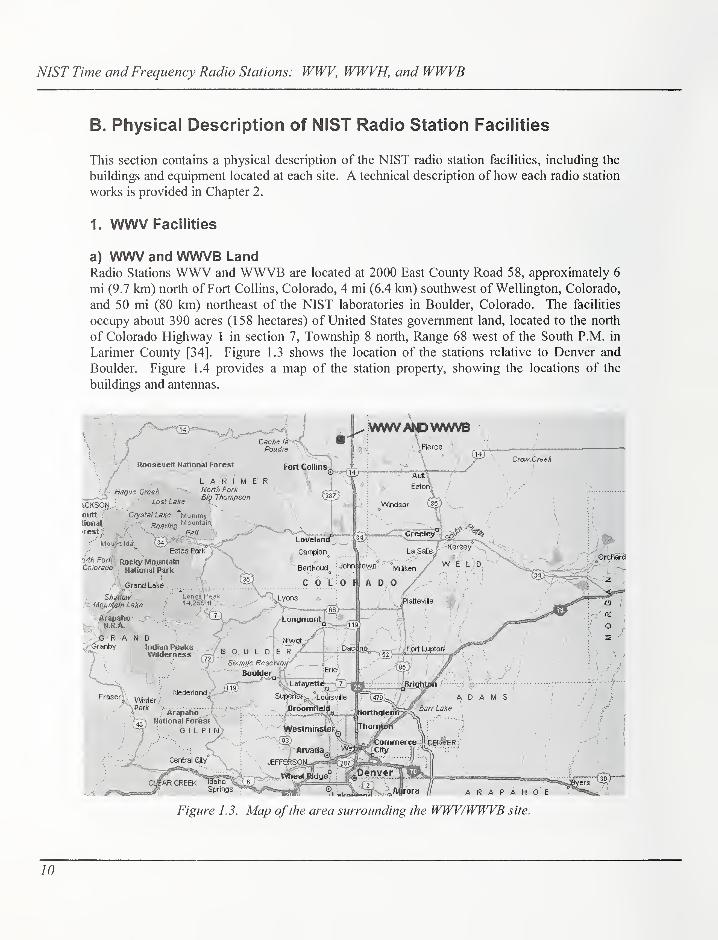
a) WWV and WWVB LandRadio Stations WWV and WWVB are located at 2000 East County Road 58, approximately 6
mi (9.7 km) north of Fort Collins, Colorado, 4 mi (6.4 km) southwest of Wellington, Colorado,
and 50 mi (80 km) northeast of the NIST laboratories in Boulder, Colorado. The facilities
occupy about 390 acres (158 hectares) of United States government land, located to the north
of Colorado Highway 1 in section 7, Township 8 north. Range 68 west of the South P.M. in
Larimer County [34]. Figure 1.3 shows the location of the stations relative to Denver and
Boulder. Figure 1.4 provides a map of the station property, showing the locations of the
buildings and antennas.
J^VWW>WWWVB
Figure 1.3. Map ofthe area surrounding the WWV/WWVB site.
10

Chapter 1 - History and Physical Description
N.W.COR.SEC. 7
S.W.COR.
SEC. 7
40°40'55,2"N
2.5MHzDIPOLE 105' 0231.3"W
\ \ -\
40" 40'50,5" N
5 MHz STBY DIPOLE 1 05° 02'26.6"W\ \ I
40° 40'47.6" NolOMHz DIPOLE 105^02'25.1"W
40"40'45.0"N^5 MHz DIPOLE
'STANDBY 105°02'24.5"W
00
00
SOUTH LINE OF SEC. 7,T8N, R68W
Figure 1.4. WWV and WWVB site map.
The terrain is gently rolling prairie, with crested wheat, buffalo grass, sagebrush, cactus, and
other vegetation found in a dry grassland environment. Some trees have been planted; most are
located near the transmitter buildings and act as wind or snow barriers as well as landscaping
elements. Lawns have also been established around the transmitter buildings, watered by
sprinkler systems. An aerial view of the site is provided in Figure 1.5.
Prior to its purchase by the federal government around 1960, the property was used as
farmland. An irrigation ditch cuts across the property from northwest to southeast, dividing it
roughly in half Another small irrigation ditch loops across the northwest comer of the
11

NIST Time and Frequency Radio Stations: WWV, WWVH, and WWVB
Figure 1.5. Aerial view of the WWV and WWVB sitefrom the south.

Chapter I - History and Physical Description
property. Water used for agricultural irrigation downstream flows through the ditches during
the local growing season, usually May to September. Two reservoirs, North Poudre Reservoir
6 and Greenwalt Lake, border the property. Both are used for irrigation during the growing
season. The water level in the reservoirs varies widely throughout the year, depending on
weather conditions and irrigation demands.
A private, members-only campground is located along the southwestern shore of Reservoir 6,
on the narrow strip of land between the station property and the lake. A guy cable anchor for
one of the towers in the WWVB antenna arrays is placed on a peninsula extending into the
northwest portion of Reservoir 6. Another peninsula extends into Greenwalt Lake; guy
anchors on this peninsula once supported a tower that has since been dismantled.
b) WWV Buildings
The WWV transmitter building was completed in 1966. It is a single-story building (Figure
1.6) of reinforced concrete block construction, and covers 6880 ft^ (639 m^). In addition to
office and utility areas, the building contains two electrically shielded enclosures, called screen
rooms, that contain the cesium frequency standards and time code generators that supply the
WWV signal to the transmitters. A laboratory area is located adjacent to the screen rooms.
The transmitters are located along an operating corridor surrounding the laboratory/screen
rooms on three sides. An equipment corridor runs behind the transmitters to allow access for
equipment maintenance and repair. The remainder of the building provides space for machine
shops and the emergency standby generator.
Figure 1.6. The WWV transmitter building.
13

NIST Time and Frequency Radio Stations: WWV, WWVH, and WWVB
The area containing the transmitters is cooled by a large evaporative cooler mounted on the
roof. In summer, outside air is taken in and passed through moistened pads, then filtered twice
before being distributed through insulated ducts to the transmitters, where it is used to cool the
equipment. From the transmitters, the air is exhausted into a ceiling plenum located above the
transmitter corridors. Four exhaust fans installed in the roof of the building are connected to a
pressure sensor; when the plenum static pressure exceeds a set point, the fans turn on and
exhaust the air to the outside. Two other manually controlled exhaust fans are ducted to the
equipment corridors. During the cooler months, the washer system is turned off and drained.
A thermostatically controlled set of louvers combines outside air with warmed transmitter
exhaust to keep the equipment operating and service areas at a moderate temperature while
cooling the transmitters. The filters remain in use year-round.
The two screen rooms are located in an area of the building that is temperature controlled by
two air conditioning systems; one is operating and the other in standby mode. The units are
switched periodically to distribute the operating hours. They include heating coils and run year
round. The systems are designed to maintain the temperature inside the screen room areas to
within 1° F of the set point, but the actual temperature varies by several degrees. The air
conditioning units currently in operation were installed in the early 1990's.
The generator room contains the electrical distribution gear. The utility company provides
power through an oil-filled, 500 kVA, Y-connected three-phase transformer. The 208 V supply
from the secondary is fed to the automatic switchgear, and then to the distribution cabinets.
Fused switches are connected to the various circuit breaker panels in the building, as well as to
each transmitter. The electrical distribution gear is original, installed when the building was
constructed in 1966.
In the event of a power outage, the switchgear automatically starts and connects the 250 kWstandby generator to the various building loads within one minute of the outage. Because the
generator is rated at a lower capacity than the utility transformer, some building loads that are
not required for station operation are not powered by the generator.
The uninterruptible power supply (UPS) installed at WWV was manufactured by Best Power
Inc., and supplies 208 V three phase power to the screen rooms and other critical loads. It is
rated at 20 kVA, and has a battery capacity of 3 1 7 minutes with the existing loads as of this
writing. It was installed in 2000. A Tripp Lite 1 kVA UPS unit is also connected to each of
the time code generators in the main screen room.
c) WWV Transmitters
The original transmitters installed at WWV were manufactured by Technical Materiel
Corporation (TMC) in the mid-1960's. These were military style transmitters of two types:
model GPT-40K, rated at 10 kW output power and used for the 5, 10, and 15 MHz broadcasts
(designated T8, T7, and T2, respectively), and model GPT-IOK, rated at 2.5 kW for the 2.5, 20,
and 25 MHz broadcasts and designated T4, T5, and T6. Each frequency then had a dedicated
transmitter and antenna, along with two standby transmitters, Tl and T3, connected to
14

Chapter 1 - History and Physical Description
broadband antennas that were capable of operating at any WWV frequency. When the 25 MHzservice was discontinued in the mid-1970's, T6 and the 25 MHz antenna were converted for
use as a standby transmitter and antenna for the 1 5 MHz broadcast. At about that same time,
signal sensing and control circuitry was installed to allow standby transmitters to be started
automatically in the event of a primary transmitter fault. Although they could be manually
reconfigured for operation at any other frequency, the two broadband transmitter/antenna
systems were normally set for operation at 5 and 10 MHz, thus providing automatic standby
systems for the three most-used WWV broadcast frequencies. Figure 1 .7 shows TMC primary
transmitter T5.
New, more efficient transmitters were
purchased for the 5, 10, and 15 MHzbroadcasts in 1990; these new 10 kWtransmitters were made by CCACorporation and designated T8-A, T7-
A and T2-A, shown in Figure 1.8. At
the same time, remote control antenna
switches were installed and connected
to the outputs of both the new CCAtransmitters and the TMC equipment
they replaced. The older transmitters
were then modified for use as standby
transmitters for the 5 MHz and 10
MHz services; when a fault occurs on
the primary CCA transmitter, the
sensing circuitry automatically starts
the standby TMC equipment and the
antenna switch connects its output to
the primary antenna. This
arrangement freed the two broadband
transmitter/antenna systems for use as
automatic standby equipment for the
2.5 MHz and 20 MHz broadcasts.
In the process of modifying the 5
MHz and 10 MHz TMC transmitters
for standby duty, it was determined
that the inefficient high-powerFigure 1.7. The 20 MHz transmitter at WWV.
amplifier section of that equipment
would be disconnected. The
transmitters were reconfigured for operation at 2.5 kW output power, making them nearly
identical to the 2.5 MHz and 20 MHz primary transmitters, which remain in operation. Figure
1.9 shows the configuration of the transmitters and antennas. The station designation,
configuration, and rated power for each transmitter are shown in Table 1.1.
15

NIST Time and Frequency Radio Stations: WWV, WWVH, and WWVB
d) WWV Antennas and Transmission Lines
Six WWV antennas are located along the top of a ridge to the north and east of the transmitter
building. The terrain in all but the southerly direction of propagation slopes downward around
the antennas. This feature of the area is used to enhance the low-angle radiation of the signal.
The transmitter building is situated at a lower elevation than the antennas to minimize its
impact on the radiation pattern [34].
The WWV primary antennas were
manufactured by Rohn, Inc. and installed
when the station was built. They are
made up of several three-sided tower
sections, measuring 18.5 in (47 cm) per
side, mounted on hinged steel bases
fastened to concrete foundations, and are
fitted with at least two sets of guy cables;
they are designed to withstand winds of
up to 112 mph (180 km/h). The sections
are made of galvanized welded steel rod.
Figure 1.10 shows one of the primary
WWV antennas.
The primary antennas and the 15 MHzstandby antenna are half-wave, vertically
polarized dipoles. They are center-fed,
that is, the connection from the
transmission line is located %-
wavelength above the ground, near the
center point of the vertical mast. The
bottom portion of the mast is electrically
grounded. The top portion is mounted on
three ceramic insulators, and makes up
the upper radiating element of the
antenna. The lower radiating element
consists of nine '/4-wavelength copper-
Figure 1.8. The 15 MHz transmitter at WWV. coated steel wires sloping downwards to
the ground at a 45° angle. Each of the
wires on this "skirt" is insulated from the ground with ceramic or fiberglass insulators. The
skirt also serves as a set of structural guy wires at the mid-point of the tower. Some WWVantennas also have a ground plane consisting of 120 tinned stranded copper wires spaced at 3°
intervals and extending outward radially from the base of the mast, each terminated at a ground
rod. WWV antenna data are shown in Table 1 .2.
16

Chapter 1 - History and Physical Description
BROADBAND#1
Tl20 MHz(STBY)
T2(OFFLINE)
BROADBAND#2
T32.5 MHz(STBY)
T2-A15 MHz
T42.5 MHz
T520 MHz
S2
T710 MHz(STBY)
T6 15 MHz(STBY)
ANTENNAFIELD
TRANSMITTERBUILDING
T7-A10 MHz
T85 MHz(STBY)
T8-A5 MHz
WWV BROADCAST CONFIGURATION
Figure 1.9. Transmitter/antenna connections at WWV.
Figure 1.10. The 15 MHz antenna at WWV.
17

NIST Time and Frequency Radio Stations: WWV, WWVH, and WWVB
Table 1.1. WWV broadcast equipment configuration.
Transmitter Frea (MHz) Configuration Power (kW) Switch 1W III iCI
T1 Anv WWVr\i 1 y V V V V V 20 MHz Standby 2.5 Rrnadhand #1
Not in Service #1
TO A1 D.U Primary 10 #1 lo ivinz "rinriary
T3 Any WWV 2.5 MHz Standby 2.5 Broadband #2
T4 2.5 Primary 2.5 2.5 MHz Primary
T5 20.0 Primary 2.5 20 MHz Primary
T6 15.0 Standby 2.5 15 MHz Primary
T7 10.0 Standby 2.5 #2 10 MHz Primary
T7-A 10.0 Primary 10 #2 10 MHz Primary
T8 5.0 Standby 2.5 #3 5 MHz Primary
T8-A 5.0 Primary 10 #3 5 MHz Primary
*Note that although transmitter T2 is connected to an antenna switch, it is not operational.
Table 1.2. WWV antenna data.
Frequency Function Height Tvnp Coordinates
Latitude Longitude
2.5 Primary 192 58.3center-fed V2-
wave dipole40° 40' 55.2" N 105° 02' 31.3" W
5.0 Primary 95 30.0center-fed 14-
wave dipole40° 40' 42.1" N 105° 02' 24.9" W
10.0 Primary 47 14.3center-fed V2-
wave dipole40° 40' 47.8" N 105° 02' 25.1" W
15.0 Primary 31 9.5center-fed V2-
wave dipole40° 40' 45.0" N 105° 02' 24.5" W
15.0 Standby 31 9.5center-fed Vz-
wave dipole40° 40' 50.5" N 105° 02" 26.6" W
20.0 Primary 23 7.0center-fed V2-
wave dipole40° 40' 53.1" N 105° 02' 28.5" W
Broadband#1
Standby 88 27.0base-fed
monopole40° 40' 44.2" N 105° 02' 29.8" W
Broadband#2
Standby 88 27.0base-fed
monopole40° 40' 50.8" N 105° 02' 32.6" W
18

Chapter 1 - History and Physical Description
13 mm mylar guys support the 10, 15,20 MHzand 1 5 MHz standby antennas - 8 mm steel cables
Precast transmission
line support post
Additional sets of guys and an additional
set of three guy anchors are used to
support the 2.5 and 5 MHz antennas
Adjustable shorted stubs -
spaced 3/8 X at operating
frequency - matches antennas
to 50 ohms
79 mm rigid line connects to
the 5-1 0-1 5 MHz antennas
41 mm rigid line connects to
the 2.5 and 20 MHz primary
and 1 5 MHz standby antennas
Figure 1.11. WWVprimary antenna and tuning stub installation.
Tuning stubs are used with the WWV primary antennas. These stubs are made of short lengths
of horizontally mounted rigid transmission line, one located at the base of the tower and
another at 3/8-wavelength toward the transmitter, each with a shorting rod inside. The rods are
moved in or out to provide the best impedance match for the transmitter, nominally 50 D..
Once set, they usually do not require adjustment. The shorting rods also provide a DC ground
for the antenna, which protects the transmitter from damage from lightning strikes. Figure 1.11
shows the details of a typical WWV primary antenna and tuning stub installation.
Two broadband monopole antennas are installed at WWV, one to the north and one to the
south of the building. These model 437C-2A antennas were manufactured by the Collins
19

NIST Time and Frequency Radio Stations: WWV, WWVH, and WWVB
Radio Company and installed whenthe station was built. They consist
of a central tower section 88 ft (27
m) tall that rests on a ceramic base
insulator, surrounded by a wire
array (Figure 1.12). A ground
plane consisting of 36 solid copper
wires extends radially irom the
tower. The wire radials are each
105 ft (32 m) long, and are
terminated at copper-clad ground
rods. Each broadband antenna is
connected to a dedicated
transmitter, and is capable of
operating at any WWV broadcast
frequency. No tuning stubs are
used in the broadband antenna
installation.
All antennas are connected to the Figure 1.12. Broadband monopole antenna at WWV.transmitters with rigid coaxial
transmission lines that are
mounted a few inches above the ground on short concrete posts (Figure 1.13). Lines to the 5,
10, and 15 MHz primary antennas, as well as one broadband standby antenna, are 3 1/8 in (79
mm) in diameter, and the lines to the other antennas are 1 5/8 in (41 mm) diameter.
The lines consist mainly of 20 ft (6.1 m) long rigid sections manufactured in the 1960's by
Prodelin Corporation. These were installed when the station was built, and extend from each
transmitter to its antenna. Most lines also have short lengths of flexible coaxial transmission
line installed to allow for bends and expansion and contraction. The flexible lengths were
installed at a later date when the original rigid fittings and elbows began to fail, and were
manufactured by Andrew Corporation with the trade name Heliax.
Three RF coaxial transfer switches are installed at WWV. The switches are made by Delta
Electronics, type 6732E, and were installed in the early 1990's. Primary and standby
transmitters are connected to the inputs of the switches, and the antenna and a dummy load are
connected to the outputs. This allows either transmitter to be operated into either load. The
switches are designed to prevent both transmitters from operating into the same load
simultaneously. Short lengths of flexible line are used inside the transmitter building to
connect the transmitters to the antenna switches.
All the transmission lines are pressurized with dehydrated air to prevent moisture from entering
the lines.
20

Chapter 1 - History and Physical Description
Figure 1.13. Transmitter to antenna transmission lines at WWV.
e) WWV Back-Up GeneratorThe WWV emergency standby generator is located in the generator room on the northwest
end of the transmitter building. It was installed when the building was constructed in 1966.
The generator is connected to an automatic transfer switch, which in the event of a
commercial power interruption will start the generator and transfer the station loads within
one minute. Sensors detect when commercial power is restored, at which time the generator
continues to carry the loads for an additional time period to allow the supply to stabilize. The
switch then transfers the loads back to commercial power.
The emergency standby generator is a Caterpillar model D343 series A, 208 V three-phase,
312 kVA 250 kW unit that is fed from an above ground ftiel storage tank. The engine is a 384
horsepower, six cylinder diesel (power ratings at sea level). The above-ground concrete fuel
tank was manufactured by Amcor Precast Inc., and installed in 1998. It has a capacity of 2000
gallons (7571 L), enough fuel to operate the station for about 4 days.
21

NIST Time and Frequency Radio Stations: WWV, WWVH, and WWVB
f) WWV Time and Frequency EquipmentTime and frequency equipment at WWV is installed in the temperature-controlled main screen
room. The "heart" of the system is three commercially manufactured cesium oscillators. Oneof the three cesium oscillators is selected as the site master clock. However, each oscillator is
connected to a time code generator (TCG), as well as other distribution and monitoring
equipment. The time code generators provide or insert all the voice and data information for
the WWV broadcast. The WWV TCGs were made by Datachron, Inc., and installed in 1991.
The master clock/TCG system is selected to send the WWV signal to the various transmitters.
However, in the event of a problem with that system, monitoring equipment automatically
disconnects it and switches to one of the other TCGs.
g) Other Equipment (Satellite Systems)Other equipment installed at the station includes two satellite earth stations, one operating on
the C band and the other on Ku band. They can be seen in Figure 1 .6. The satellite systems are
used periodically to perform time transfers with other standards laboratories, both in the United
States and abroad.
The C-band equipment consists of an Andrew model 237230 4.6 m antenna, Miteq up- and
down-converters and a Kamen high power amplifier rated at 20 W. The Ku-band equipment
consists of a Vertex model 4.5-KPK 4.5 m antenna also with Miteq converters and a 2 Wamplifier.
22

Chapter 1 - History and Physical Description
2. WWVB Facilities
a) WWVB LandWWVB was first to occupy the site it now shares with WWV (See l.a.).
b) WWVB Buildings
Construction ofWWVB began in 1962. The single-story WWVB transmitter building (Figure
1.14) is of manufactured steel panel construction, and was assembled on-site on a concrete
slab. The original building, made by Butler Manufacturing, includes a transmitter room, two
electrically shielded spaces known as
screen rooms, a laboratory area, and a
small restroom. It was completed in
1963. An administrative wing including
two offices, a reception area, conference
room, restrooms, and a small galley was
added in 1966. An additional wing for
more transmitters was added in 1996,
and a generator room was added in
2000. In total, the WWVB transmitter
building contains 5476 (508.7 m^) of
interior space.
Two smaller buildings known as helix
houses are located underneath the
antennas, near the center of each. These
buildings were also made by Butler
Mfg., and were assembled along with
the transmitter building. They contain
equipment to match the impedance of
the antennas to that of the transmitters.
The electrical connection from
transmitter to antenna is made in the
helix house. Figure 1.15 shows one of
the helix houses.Figure 1.14. View ofWWVB building.
The WWVB electrical system consists of an oil-filled 500 kVA Y-connected, three-phase
transformer located outside the west wall of the main building and connected to the utility
power feeder. The secondary of the transformer supplies 480 V, three-phase power to the main
breaker panel, which is connected to the automatic transfer switch and then to other distribution
panels that feed the transmitters, some electric heaters, and outbuildings. A step-down
transformer is used to provide 208 V three-phase power for all other loads. The electrical
distribution system was completely upgraded fi-om 1997 to 2001, with new panels and some
new circuits.
25

NIST Time and Frequency Radio Stations: WWV, WWVH, and WWVB
Figure 1.15. WWVB helix house.
The uninterruptible power supply (UPS) at
WWVB was made by Best Power, model UT-310. It has a 208 V three-phase output, and is
rated at 10 kVA. The estimated run time with a
normal load is more than three hours as of this
writing. It was installed in 2000. Three 1 kVATripp Lite UPS units are also connected to the
time code generators in the main screen room.
The transmitter rooms in the WWVB building
are heated in winter by the transmitter exhaust
air, which is recycled using thermostatically
controlled ductwork louvers to maintain
moderate room temperatures. Backup unit
heaters are also installed in one of the
transmitter rooms. In summer, the heated
transmitter exhaust air is ducted outside, and the
rooms are cooled by evaporative coolers.
The main screen room at WWVB is kept at a
constant temperature by two air conditioning
units, one operating and the other in standby
mode. The units are switched periodically to
distribute the operating hours evenly. The air
conditioning units are from the original
installation, but have been repaired and
modified many times over the years. The
auxiliary screen room at the WWVB building is
heated by the lab area heating system.
c) WWVB Transmitters
Continental Electronics, Inc. originally manufactured the WWVB transmitters for the U.S.
Navy. Given the model number 218B by the manufacturer, they are also known by their
military designation as the AN/FRT-72. They were built in the mid-1 960's and installed at
various naval communications stations around the world. As time passed, the Navy began a
transmitter overhaul program to upgrade and modernize the equipment. In the 1990's, the
Navy began to close some of the facilities using these transmitters, and the equipment was
removed and placed in storage. Discussions between agencies at the highest levels resulted in
several of these transmitters and other broadcast equipment being transferred to NISTbeginning in the mid-1990's to replace WWVB's obsolete equipment.
24

Chapter I - History and Physical Description
Figure 1.16. WWVB transmitter.
Currently, three AN/FRT-72 transmitters are installed at WWVB, and designated as low
frequency transmitters LFT-1, LFT-2, and LFT-3. All have all been overhauled as part of the
Navy's transmitter overhaul program, with further upgrades performed by NIST. Each
transmitter consists of six cabinets housing different elements of the equipment. The transmitter
cabinets are arranged side-by-side, and the entire transmitter is 24 ft (7.3 m) long by 3 ft (0.9 m)deep and 6.5 ft (2 m) high. The transmitters are rated for 50 kW average power output at 100 %duty cycle. They are wired for 480 V input, and require about 140 kVA of power per
transmitter to operate at normal output levels. Figure 1.16 shows one of the WWVBtransmitters.
The transmitters are controlled from a control console and RP switch assembly located in the
main transmitter room near LFT-3. Using the RF switch, known as a switch matrix, an operator
can connect any transmitter to either antenna or a dummy load. The control console allows an
operator to select single or dual antenna operation, as well as energize and set power output
levels for the transmitters, and also monitor forward and reflected power levels, antenna current,
configuration status, utility power quality, and weather information. Figure 1.17 shows the
WWVB broadcast equipment configuration. Figure 1.18 shows the dummy load on the left, and
the switch matrix on the right.
25

NIST Time and Frequency Radio Stations: WWV, WWVH, and WWVB
SOUTHANTENNA
NORTHANTBWA
lEGEND:
60 kHz Tȣ SIGNAL -
THBlCTRY
e MHz REFERENCE
\/
House
\/
HBJ(HOUSE
SaECTHJTine CODSGENERATOR(10F4)
SITEULSTERCLOCKATWWV
LALF
TRANSI*eTTER
#1
LF
TRANSMITTER#2
LFTRANSMITTER
#3
RFSWITCHMATRIX
DUMMYLOAD
Figure 1.
1
7. WWVB broadcast equipment configuration.
d) WWVB AntennasThe two WWVB transmitting antennas are
situated to the northwest and southeast of the
transmitter building. They are referred to as
the north and south antennas. Figure 1.19
shows an artist's rendering of the WWVBantennas. Although the two top-loaded
monopole antenna systems are nearly identical,
the north antenna was originally used for the
20 kHz WWVL broadcast. The antennas were
designed by W.W. Brown, consultant to NBS,
and were erected in 1962-63. Each antenna
system consists of three parts: four towers, a
capacitance hat or top hat and downlead, and
the ground plane.
The four towers in each antenna system areFigure 1.18. Dummy load and switch matrix..
arranged in a diamond pattern. Each tower is
held in place by three sets of guy cables, with three cables in each set. All towers except tower
2 in the south antenna are 400 ft (122 m) high; tower 2 is 415 ft (126.5 m) high, due to its base
26

Chapter I - History and Physical Description
North Antenna
" 573 m
Figure 1.19. WWVB antennas.
being at a lower elevation than the bases of the other towers. The towers are made of welded steel
rod in 30 ft (9.1 m) sections. Each section has three sides that measure 4 ft (1 .2 m) per side. The
sections are stacked and bolted one on top of another, and are painted red and white in accordance
with Federal Aviation Administration regulations. Red flashing beacons and side marker lights
are installed on each tower. The lights are controlled by a photocell, or light-activated switch, and
are turned on automatically when daylight fades. The towers are electrically grounded at their
bases; insulators are installed on each guy cable near the guy anchor.
The towers support the aerial elements of the antenna, known as the capacitance hat or top hat and
the downlead. The top hat is a series of aluminum cables arranged horizontally in a diamond
shape, with a tower at each comer of the diamond. The top hat is not fastened directly to the
towers but instead is connected to porcelain insulators, which in turn are connected to steel cables
that extend down the face of each tower to a 5000 lb (2268 kg) concrete counterweight near the
base. This allows the top hat to be electrically isolated from the towers. The cables run over
sheaves mounted at the top of each tower. This arrangement allows the top hat to "float" between
the towers, tensioned by the counterweights that keep it nearly parallel to the ground. Figure 1 .20
shows the antenna connections at the top of one tower, and Figure 1.21 shows a counterweight
assembly. The downlead is made up of six aluminum cables with steel cores arranged around a
27
NIST Time and Frequency Radio Stations: WWV, WWVH, and WWVB
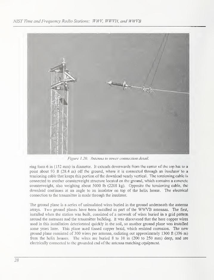
Figure 1.20. Antenna to tower connection detail.
ring form 6 in (152 mm) in diameter. It extends downwards from the center of the top hat to a
point about 93 ft (28.4 m) off the ground, where it is connected through an insulator to a
tensioning cable that keeps this portion of the downlead nearly vertical. The tensioning cable is
connected to another counterweight structure located on the ground, which contains a concrete
counterweight, also weighing about 5000 lb (2268 kg). Opposite the tensioning cable, the
downlead continues at an angle to an insulator on top of the helix house. The electrical
connection to the transmitter is made through the insulator.
The ground plane is a series of uninsulated wires buried in the ground underneath the antenna
arrays. Two ground planes have been installed as part of the WWVB antennas. The first,
installed when the station was built, consisted of a network of wires buried in a grid pattern
around the antennas and the transmitter building. It was discovered that the bare copper wires
used in this installation deteriorated quickly in the soil, so another ground plane was installed
some years later. This plane used tinned copper braid, which resisted corrosion. The newground plane consisted of 300 wires per antenna, radiating out approximately 1300 ft (396 m)
from the helix houses. The wires are buried 8 to 10 in (200 to 250 mm) deep, and are
electrically connected to the grounded end of the antenna matching equipment.
28

Chapter 1 - History and Physical Description
e) WWVB Back-UpGeneratorThe emergency standby
generator was installed in
2000 in the newlyconstructed generator roomat the northwest end of the
WWVB building. It
replaced a smaller unit that
was installed outside. It is
connected to an automatic
transfer switch, which in the
event of a commercial power
interruption will start the
generator and transfer the
station loads within one
minute. Sensors detect whencommercial power is
restored, at which time the
generator continues to carry
the loads for an additional
time period to allow the
supply to stabilize. The
switch then transfers the
loads back to commercial
power.
The WWVB emergency
standby generator is an Onani
model DFED-3370866. It is
standby rated at 625 kVA,500 kW at sea level, and has
a 480 V three-phase output.
The engine is a six cylinder supercharged diesel rated at 755 horsepower at sea level, fed from
a 1000 gallon (3785 L) above ground fliel storage tank which was installed in 1998. The
generator was installed in 2000.
Figure 1.21. Tower coimicrwcigln.
29

NIST Time and Frequency Radio Stations: WWV, WWVH, and WWVB
f) WWVB Time and Frequency EquipmentWWVB time and frequency equipment consists of four time code generators (TCGs) located in
the WWVB main screen room. These units (Model 9110) were manufactured in the late
1970's by Datum, Inc. Various distribution and monitoring equipment are also located in the
screen room.
The selected TCG is connected to a reference frequency that is supplied by the site master
clock, located in the WWV building about '/i mile (0.4 km) away and sent to the WWVBbuilding via underground cables.
30

Chapter 1 - History and Physical Description
^ MOiOKA!
PACIFICOCEAN
5^,THE NA PALI
COAST ,,
PUIJ KA ^PUi *
fORfST ^
PACIFICOCEAN
WWVH
barking
Sands
^Mana
C550
WAIM(A
'
CANYONSTATCPARK
(-jKekaha
(so;
\
- oWaimea
K/la/ika/ti
Channel
Xyanapepe^
.Airport^Mu<jntai[;
, OPrlnceville
~"o X Kilaue
iir NORTH Hanalei "SHORE 5.
3 KulliO
KalaheoO
ISUY
AnaholaO
%^ THE COCONUT M
'MX. Wiakilf
COAST
'ssf : o
O'Kealia
'Kapaa
UHUE
50
Puhi O
Cssg^i "wailua
9waipouli
>
eg?nHariamaulu
T" Lihue Airport
Lawai ILirbor
'"'"^lu^^^,V,„,„v,W,-
;^ Kaitiii
O Koloa ^ ' Channeli^y, THE POIPlT—
' RES0RT:AREA
Poipu°
'
Figure 1.22. Map ofKauai, Hawaii.
3. WWVH Facilities
a) WWVH LandWWVH occupies a 30 acre (12 hectare) site near the town of Kekaha, on the western side of
the island of Kauai, Hawaii. The land is leased from the U.S. Navy, and is surrounded by the
Navy's Barking Sands Pacific Missile Range Facility. The parcel is located on the shoreline of
the island. A map of Kauai,
showing the location of the station
is shown in Figure 1.22. The
terrain is flat, coastal land, with a
few low dunes next to the beach.
Figure 1 .23 shows a view of the
building from the entrance, and
Figure 1.24 shows an aerial view
of the site. The soil is mostly
sand. Shoreline scrub and bushes
cover the site, with a few low
trees. A lawn area has been
established around the building,
with palm trees, ornamental
bushes and flowering plants.
Figure 1.23. Entrance to WWVH site.
31

NIST Time and Frequency Radio Stations: WWV, WWVH, and WWVB
Figure 1.24. View ofWWVH sitefrom the top ofthe 5 MHz antenna.
b) WWVH Buildings
The WWVH transmitter building (Figure 1.24) is a single story concrete block structure located
at the eastern edge of the site. It was built in 1971, and covers a total area of 4482 ft^ (416.4
m^). The building contains a transmitter room, along with laboratory space, two screen rooms,
a reception area, several offices, a small kitchen, and restrooms. A central corridor runs the
length of the building from the reception area to the transmitter room entrance. A wing
contains electrical distribution equipment and a standby generator.
The transmitter room is cooled by two split-system air conditioning systems; the transmitters
are cooled by outside air that is ducted to the transmitter air intakes. Warm exhaust air is
ducted outside.
The building contains two screen rooms. The main screen room is where the broadcast time
code generators and cesium clocks are located; an adjacent auxiliary screen room is used for
monitoring equipment as well as any work that requires an electrically shielded environment.
The rooms are cooled by an air conditioning system of the split-system type, mounted inside
the main screen room. The split systems have an evaporator and fan unit mounted on an
interior wall, connected with piping and wiring to a condenser and compressor unit located
outside. Both systems cool the main screen room directly, and cool air is ducted from the
main to the auxiliary screen room.
32

Chapter 1 - History and Physical Description
c) WWVH Transmitters
WWVH operates on four frequencies: 2.5, 5, 10,
and 15 MHz, with a primary transmitter and
standby transmitter for each frequency. The first
transmitters installed at the current WWVH site
were made by AEL Corporation and installed in
1971. Seven of this type were originally installed;
in 1983, two were removed and replaced with
three newer, more efficient transmitters made by
Elcom-Bauer Corporation. These units became the
primary transmitters on 5.0, 10.0 and 15.0 MHz;Figure 1.25 shows the Elcom-Bauer 5 MHzprimary transmitter. One of the older units was
retained as the primary 2.5 MHz transmitter, while
the others were modified to be used as standby
transmitters. Figure 1.26 shows the AEL 15 MHzstandby transmitter. Table 1.3 shows the WWVHtransmitter configuration
1 _'Hi ^El 1.—
. _.. -..-i-iJ MtC£«. ^mmIT HI SiOmhz '
H .'
r
[
III
1j
Figure 1.25. The 5 MHz transmitter at WWVH.
d) WWVH Antennas
I
The WWVH antennas are of two types:
omnidirecfional and phased array. The omni-
directional antennas radiate the same power level in
every horizontal direction away from the tower, while
the phased-array antennas are designed to radiate more
power toward the west of the station. The 2.5 MHzantennas as well as the permanent standby antennas are
omnidirecfional towers, while the 5.0, 10.0, and 15.0
MHz primary antennas are phased arrays. The 15 MHzstandby antenna is a temporary, prototype phased array
consisting of two quarter-wave monopoles. The
WWVH antennas are described in more detail in Table
2.7 in Chapter 2.
A 41 ft tall (12.5 m) grounded steel tower serves as a
platform for various HF and National Weather Service
receiving antennas, but is not used for the time and
frequency broadcasts.
The original omni-directional towers were vertical steel
structures made by Rohn or Collins, similar to the
Figure 1.26. The 15 MHz standby trans- WWV antennas. However, due to the high humidity
mitter at WWVH.
33

NIST Time and Frequency Radio Stations: WWV, WWVH, and WWVB
Table 1.3. WWVH transmitter configuration.
1 ransminerdesignation
rrequency(IVIHz)
^oniiguraiion ^)AiAfArrower(kW)
AntAnnoMnienna
T1 5 Primary 10 5 MHz Primary
T2 Any WWVH 5 MHz Standby 5 Broadband #1
T3 15 Standby 5 15 MHz Standby
T4 15 Primary 10 15 MHz Primary
T5 10 Primary 10 10 MHz Primary
T6 2.5 Primary 5 2.5 MHz Primary
T7 Any WWVH 10 IVIHz Standby 5 Broadband #2
T8 2.5 Standby 5 2.5 MHz Standby
and salt spray from the nearby ocean, these towers required much more maintenance and
upkeep. Beginning in 2001, these antennas were replaced by free-standing fiberglass masts
(also known as whip antennas), manufactured by Valcom Ltd. The new monopole antennas are
made up of several hollow, tapered epoxy-fiberglass sections, which are joined together end-to-
end with threaded bronze ferrules. Embedded in the epoxy-fiberglass sections are strips of
copper extending the length of each section, usually in a spiral and connected to the threaded
ferrules. The top section is capped either with a bronze corona sphere or a hoop shaped
capacitive element. The base of the bottom section flares outward to meet the mounting
flange. The embedded copper strips end at the feed point about 46 cm above the flange, thus
the bottom 46 cm of the mast forms the base insulator. No guy cables are required. Figure
1.27 shows one of the whip antennas.
The fiberglass whip antennas have external matching equipment located in a weatherproof box
next to the antenna base. All whip antennas are mounted on hinged stainless steel plates, that
allow the tower to be lowered for painting or maintenance. Ground planes are installed at each
tower, consisting of 1 20 solid copper wires extending radially outward from a center ring at the
base of the tower. The wires are buried several inches deep, and each wire is terminated to a
ground rod, a 10 ft (3 m) long copper-coated steel rod driven into the earth. The lengths of the
ground radials vary, depending on the frequency for which the tower was designed [35].
The primary phased-array antennas were manufactured by Rohn Inc., and installed when the
station was built in 1971. Each array consists of two half-wave dipole towers spaced a quarter-
wavelength apart. Each tower consists of stacked three-sided steel sections, with ceramic
34

Chapter 1 - History and Physical Description
insulators near the mid-point of the tower. Adrawing showing an overhead and side view of
a phased array can be seen in Figure 1 .28. Theantennas are center-fed, that is, the connection
from the transmission hne is located near the
electrical center point of the vertical masts. The
bottom portions of the masts are electrically
grounded. The top portions are each mounted
on three ceramic insulators, and make up the
upper radiating elements of the antenna. The
lower radiating elements consist of nine copper-
coated steel wires per tower sloping downwardto the ground at a 70° angle. Each of the wires
on these "skirts" is isolated from electrical
ground using ceramic insulators. The skirts also
serve as a set of structural guy wires. The
antennas also have a ground plane consisting of
120 copper wires spaced at 3° intervals,
extending outward radially from the base of
both masts, each terminated at a ground rod.
Figure 1 .29 shows the 1 5 MHz primary antenna.
Each phased array antenna is connected to a
stub tuning network, located at the base of the
towers. This network is made of sections of 1
5/8 in (41 mm) diameter rigid coaxial
transmission line, and allows the antennas to be
matched precisely to the impedance of the
transmitters. Flexible transmission line, installed when the station was built, connects the stub
tuning networks to the transmitters. The 1 5/8 in (41 mm) transmission line is buried 3 ft (0.9
m) underground for the length of the run, coming to the surface at the building and antenna.
Figure 1.27. Fiberglass whip antenna at
WWVH.
e) WWVH Back-Up GeneratorThe WWVH emergency standby generator was installed in April 2003 in the transmitter
building. It replaced the original unit, which had become unreliable due to age. It is connected
to an automatic transfer switch, which in the event of a commercial power interruption will start
the generator and transfer the station loads within 20 s. Sensors detect when commercial power
is restored, at which time the generator continues to carry the loads for an additional 30 minutes
to allow the supply to stabilize. The switch then transfers the loads back to commercial power.
The WWVH emergency standby generator was manufactured by Kohler. It is standby rated at
525 kVA, 425 kW at sea level, and has a 208 V three-phase output. The engine is a six cylinder,
14.0 L (855 cu in), turbocharged diesel rated at 635 bulk horsepower at sea level, fed from a
2000 gallon above ground fiiel storage tank that was installed in 1991
.
35

NIST Time and Frequency Radio Stations: WWV, WWVH, and WWVB
Figure 1.28. Phased-array antenna at WWVH.
36
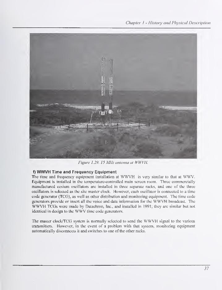
Chapter 1 - History and Physical Description
Figure 1.29. 15 MHz antenna at WWVH.
f) WWVH Time and Frequency EquipmentThe time and frequency equipment installation at WWVH is very similar to that at WWV.Equipment is installed in the temperature-controlled main screen room. Three commercially
manufactured cesium oscillators are installed in three separate racks, and one of the three
oscillators is selected as the site master clock. However, each oscillator is connected to a time
code generator (TCG), as well as other distribution and monitoring equipment. The time code
generators provide or insert all the voice and data information for the WWVH broadcast. The
WWVH TCGs were made by Datachron, Inc., and installed in 1991; they are similar but not
identical in design to the WWV time code generators.
The master clock/TCG system is normally selected to send the WWVH signal to the various
transmitters. However, in the event of a problem with that system, monitoring equipment
automatically disconnects it and switches to one of the other racks.
37

NIST Time and Frequency Radio Stations: WWV, WWVH, and WWVB
C. Organizational Control of NIST Radio StationsEach NIST Radio Station is managed, controlled, and maintained by the Services Group of the
NIST Time and Frequency Division. The engineer-in-charge (EIC) at each station reports to the
Group Leader of the Services Group, who reports to the Division Chief of the Time and
Frequency Division, who in turn reports to the Director of the NIST Physics Laboratory. The
Physics Laboratory is one of the seven operational units of NIST, which is an agency of the
United States Department of Commerce's Technology Administration.
The staff at the radio stations currently consists of an EIC, a technical staff, and one administrative
staff member. WWV and WWVB have a combined staff, with one EIC, three electronics
technicians, and a part time administrative assistant. The WWVH staff consists of the EIC, two
technicians, and an administrative assistant.
Normal staff working hours are from 6:30 a.m. to 5:00 p.m. Mountain Time, Monday through
Friday at WWV/WWVB, and 7:30 a.m. to 4:00 p.m. Hawaii Time, Monday through Friday at
WWVH. Staff members are on call outside these hours for emergency response due to broadcast
outages.
38

Chapter 2 - Technical Description
Chapter 2
Technical Description
This chapter provides a technical description ofhow the NIST radio stations work. It describes
the equipment used at each station to broadcast standard time and frequency signals to the
United States.
A. How the NIST Radio Stations WorkThe mission of the NIST Radio Stations is to distribute NIST time of day, time interval, and
standard frequency information to industry, government, and the general public in the United
States. The time and frequency information contained in the broadcasts is derived from the
NIST Time Scale, UTC(NIST), which is maintained in Boulder, Colorado. UTC(NIST), an
ensemble of commercial cesium and hydrogen maser oscillators, is calibrated using the NISTPrimary Frequency Standard, which as of this writing is a cesium fountain oscillator known as
NIST-Fl. UTC(NIST) is disseminated using a variety of means besides the radio stations
(Figure 2.1). Other broadcast services operated by the NIST Time and Frequency Division
include the Telephone Time of Day system discussed later, the Internet Time Service (ITS),
the Automated Computer Time Service (ACTS), and the time.gov web sites [36].
The radio stations are each equipped with a set of three commercial cesium oscillators or
frequency standards (WWV and WWVB share one set). The fi^equency standards are
compared with UTC(NIST) every working day using the GPS common-view technique, and
steered when necessary. They are connected to monitoring equipment that constantly
compares their outputs and removes one from service if it fails.
One of the oscillators is selected as the station standard, or site master clock. This standard is
connected to a time code generator, which creates the signal that is fed to the transmitters for
broadcasting at the various frequencies. The time code generators are also monitored for
accuracy. The WWV and WWVH audible signals are also sent to the telephone time-of-day
equipment, where they can be accessed by telephone.
The WWV and WWVH broadcast formats are very similar. The most obvious difference to
the listener is that the WWV voice time announcements are made using a male voice, and the
WWVH announcements use a female voice to avoid confusion between the two stations since
both can be received in some areas.
Since WWVB is located at the same site as WWV, these two stations share one site master
clock. Separate WWVB time code generators develop the WWVB broadcast format which is
transmitted at 60 kHz. The WWVB broadcast contains a machine readable time code, but no
audio information.
39
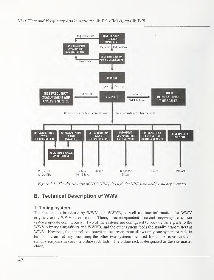
NIST Time and Frequency Radio Stations: WWV, WWVH, and WWVB
Frequency Data NIST PRIMARYFREQUENCY
\ STANDARD
INTERNATIONAL
ATOMIC TIMESCALES (TAI, UTC)
iTime Data
Periodic I Calibrations
NIST ENSEMBLE OF
ATOMIC OSCILLATORS
T
NIST FREQUENCYMEASUREMENT ANDANALYSIS SERVICE
Leap I Seconds
Satellite Links
OTHERINTERNATIONAL
TIME SCALES
Connparisons made via common-view measurements and other methods
HF RADIO STATION
WWV(FT. COLLINS, CO)
HF RADIO STATION
WWVH(KAUAI, HI)
LF RADIO STATION
WWVB(FT. COLLINS, CO)
;
AUDIO TIME SIGNALS
VIA TELEPHONE
AUTOMATEDCOMPUTER TIME
SERVICE (ACTS)
INTERNET TIME
SERVICE (ITS)
(MUTIPLE SERVERS)
1NIST.TIME.GOV
WEB SITE
2.5, 5, 10,
15, 20 MHz
2.5, 5, 60 kHz
10. 15 MHzTelephone
System
Internet Internet
Figure 2. 1. The distribution ofUTC(NIST) through the NIST time andfrequency services.
B. Technical Description of WWV
1. Timing systemThe frequencies broadcast by WWV and WWVB, as well as time information for WWVoriginate in the WWV screen room. There, three independent time and frequency generation
systems operate continuously. Two of the systems are configured to provide the signals to the
WWV primary transmitters and WWVB, and the other system feeds the standby transmitters at
WWV. However, the control equipment in the screen room allows only one system or rack to
be "on the air" at any one time; the other two systems are used for comparisons, and for
standby purposes in case the online rack fails. The online rack is designated as the site master
clock.
40

Chapter 2 - Technical Description
Figure 2.2 shows a simplified block diagram of a WWV broadcast equipment rack and its
interconnections with monitoring and control equipment. Each system is made up of a
commercial cesium frequency standard, a frequency divider/distribution amplifier, a time code
generator (TCG), monitoring and ancillary outputs, and an equipment rack. Each cesium
frequency standard produces an extremely stable 5 MHz frequency reference output that is fed
to a divider/distribution amplifier that distributes the signal to the time code generator, a 5 MHzto 1 pulse-per-second (pps) divider, and the Frequency Measurement and Analysis System
(FMAS) [37]. The 5 MHz is also divided to 1 MHz and sent to the screen room controller.
INPUT FKIMBROADCASTMONITOR
ALARMOUTPUTS
to Akrm Monioring
Company Equipm*nl
lo Ptging Sytttm
CESIUMFREQUENCYSTANDARD
5 MHz
>\
FREa DMDERANO
DISTRIBUTION
AMPLIFIER
SMHz
WWVSIGNAL
! GENERATIONSYSTEMRACK A(1 OF 3)
SMHz/ \
1MHz
TIMECODE
TIME CODEGENERATOR
6 MH2 - 1 PPSDMOER
STATIONREFERENCE
1 PPS
FREQUENCYSAMPLE ANDVMECODE
1MHzFROMRACKSBiC
TIME CODEFROM -RACKSB&C
SCREENROOM
CONTROLLERUNIT
S»l»et»d1 MHz(0 SMich
md DMributhn Uiul
Monlondl MHz
^ (o Standby
TnmmUtrModiMor
FREQUENCYSAMPLE ANDTIME CODEFROM RACKS
BiC
WWVrimtCod*to datt loggtr
FREQUENCYAMD TIME CODECOMPARATOR
^ Tant InlwlCourttr
to FMAS
Figure 2.2. WWV broadcast equipment rack.
One of the two systems that provides the signals to the primary WWV and WWVB transmitters
is designated as the site master clock. This system forms the basis of all the frequencies used
or transmitted at WWV and WWVB.
2. Broadcast FormatThe WWV broadcast format consists of several elements. The format contains standard carrier
frequencies, standard audio frequencies, time intervals, voice time announcements, a binary
41
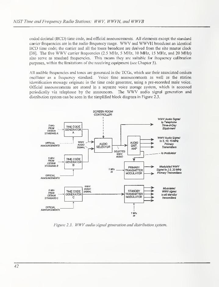
NIST Time and Frequency Radio Stations: WWV, WWVH, and WWVB
coded decimal (BCD) time code, and official announcements. All elements except the standard
carrier frequencies are in the audio frequency range. WWV and WWVH broadcast an identical
BCD time code; the carrier and all the tones broadcast are derived from the site master clock
[38]. The five WWV carrier frequencies (2.5 MHz, 5 MHz, 10 MHz, 15 MHz, and 20 MHz)also serve as standard frequencies. This means they are suitable for frequency calibration
purposes, within the limitations of the receiving equipment (see Chapter 5).
All audible frequencies and tones are generated in the TCGs, which use their associated cesium
oscillator as a frequency standard. Voice time announcements as well as the station
identification message originate in the time code generator, using a pre-recorded male voice.
Official announcements are stored in a separate voice storage system, which is accessed
periodically via telephone by the announcers. The WWV audio signal generation and
distribution system can be seen in the simplified block diagram in Figure 2.3.
SCREEN ROCOACONTROLLER
SUHzFROMCESIUM
STANDARD A
OFFICIAL
ANNOUNCEMEIfTS
5 MHzFROMCESIUM
STANDARD B
TIME CODEGENERATOR
A
WWV ^AUDIOSIGNAL^
TIME CODEGENERATOR
B
OFFICIALANNOUNCEMENTS
AUDIOSELECTOR
\
SELECTEDwmAUDIO
AUDIODIST.
AMP
1 MHzIN
PRIMARY >TRANSMFTTERMODULATOR >
WW\/ Audio Signal
to Telephone
Time-of-Day
Equipment
WWV Audio Signal:
to 5, 10, 15 MHzPrimaiy
Transmitters
to modulator
Modulated WWVSignal to 2.5, 20 MHzPrimary Transmitters
5 MHzFROMCESIUM
STANDARD C
OFFICIALANNOUNCEMENTS
TIME CODEGENERATOR
C
AUDIOSIGNAL STA^C>BY
TRANSIvffTTER
MODULATOR
1MHzIN
Modulated
WV\/V signal
to all ^andbytransmitters
Figure 2. 3. WWV audio signal generation and distribution system.
42

Chapter 2 - Technical Description
a) Standard Carrier FrequenciesThe WWV standard carrier frequencies are derived directly from the site master clock. Figure
2.4 shows a simplified block diagram of the standard carrier frequency generation system. A 1
MHz signal is sent from each time and frequency generation system rack to the screen roomcontroller. The controller sends the selected signal from system A or B to the 1 MHz switch
and distribution unit. From there, the signal is sent directly to the 5, 10, and 15 MHz primary
transmitters, and also to the 2.5 and 20 MHz primary transmitter modulators, which create the
composite audio signal for those transmitters. The controller sends the 1 MHz signal from rack
C to the standby transmitter modulator.
CESUMFREQUENCYSTAhTOARO
TIME ANDFREQUENCYGENERATIONSYSTEM A
(SELECTED)
CESIUMFREQUENCYSTANDARD
TIME ANDFREQUENCYGEhERATlONSYSTB^B
CESIUMFREQUENCYSTANDARD
TWEANDFREQUENCYGENERATIONSYSTEM
C
5 MHz FREQ. DMDERAND
DISTRIBUTION
AMPLIFIER
SMHz(0
WWVB
1 UHi
SMHz
TIME CODEGENERATOR
SMHz FREQ. DIVIDER
ANDDISTRIBUTION
AMPLIFIER
SMHzto
wwve
SMHz
TIME CODEGENERATOR
SMHz
Contmllf
iS«fecf*<ff MHzloPrimuy Tmnemilm
1 MHz SWITCHAND
DISTRIBUTION
UNIT
1 MHz oalpul
to 5. 10, 15 MHz
Audio
input
PRIMARYTRANSMITTERMODULATOR
Innamilera
ModiM»dWmaigntIto2.S 20 MHzInnamitwa
FREQ. DMDERAND
DISTRIBUTION
AMPUFIER
1MHz '
^1
1 \f
)
SMHz 1
^1 Audio
STANDBYTRANSMITTERMODULATORTIME CODE
GENERATOR
1 input
Modulated
WWV signal
to all attndby
Iranamitm
Figure 2. 4. WWV standard carrierfrequency generation system.
b) Voice Time AnnouncementsThe most popular element of the WWV broadcast is undoubtedly the voice time of day
announcements, broadcast once each minute. The WWV voice time announcement is madeusing a male voice, and begins about 7 seconds before the beginning of the minute. Anexample of the voice time announcement for 0725 UTC would read:
43

NIST Time and Frequency Radio Stations: WWV, WWVH, and WWVB
"At the tone: seven hours, twentyfive minutes, coordinated universal time."
This announcement is followed by a short 1000 Hz tone. The time announcement is
concatenated, or assembled from a variety of digitally stored phrases or enunciated words. All
the phrases and words are recordings of a human voice.
A station identification message using the same male voice is broadcast at the beginning and
mid-point of each hour. The station ID reads as follows:
"National Institute of Standards and Technology time: this is Radio Station
WWV, Fort Collins Colorado, broadcasting on internationally allocated
standard carrier frequencies of two-point-five, five, ten, fifteen, and twenty
megahertz, providing time of day, standard time interval, and other related
information. Inquiries regarding these transmissions may be directed to the
National Institute of Standards and Technology, Radio Station WWV, 2000
East County Road 58, Fort Collins, Colorado, 80524."
The WWV station ID announcement lasts about 35 seconds, and is broadcast during the minute
following the tone that marks the beginning or midpoint of each hour. For example, the
announcement runs at 1100 UTC and 1130 UTC. It is stored in its entirety in electronic
memory in the time code generator.
c) standard Time intervals
Standard time intervals broadcast on WWV are indicated by various tones of various lengths.
Intervals of seconds, ten seconds, minutes, hours, and days are all part of the broadcast. The
time intervals are indicated as follows:
• Seconds: bursts of 1000 Hz tone; most are 5 ms long, which simulates the ticking of a
clock. These pulses or "ticks" are omitted on the 29"^ and 59"^ seconds. The second that
begins each minute is indicated by a longer tone.
• Ten seconds: indicated on BCD time code.
• Minutes: 800 ms burst of 1000 Hz tone at the beginning of every minute except the
beginning of the hour.
• Hours: 800 ms burst of 1 500 Hz tone at the beginning of every hour. Also, the 440 Hz tone
is broadcast once each hour, at minute 2 on WWV and minute 1 on WWVH, except for the
first hour of each day.
• Days: There is no formal day marker, but the 440 Hz tone described above is omitted
during the first hour of each day.
44

Chapter 2 - Technical Description
d) Standard Audio FrequenciesIn addition to the inaudible standard carrier frequencies, WWV also broadcasts standard audio
frequencies during most minutes of every hour. Figure 2.5 is an illustration of the WWV audio
signals. Tones of 500 Hz and 600 Hz are broadcast on alternating minutes, and a 440 Hz tone
is broadcast once each hour, except the first hour of the day. The tones are inserted in the
broadcast for the first 45 seconds of their allocated minutes, and are followed by a silent period
and the voice announcement indicating the time (Figure 2.5 inset). The seconds pulses
interrupt the tones briefly; each pulse is preceded by 10 ms of silence and followed by 25 ms of
silence. The entire "protected zone" around each pulse is shown in Figure 2.6. This
arrangement makes the pulse easier to discern; however, the short silent periods around each
pulse are nearly unnoticeable.
Broadcast FormatVia telephone (303)499-71 1 1
(NotaToll-FreeNumber) -Station ID
440 Hz 1-Hour Mark
NIST Reserved
GPSReports
NIST Reserved
Geoalerts
Station ID
• BEGINNING OF EACH HOUR IS IDENTIFIED BY 0.!
SECOND LONG, 1500 Hz TONE.
• BEGINNING OF EACH MINUTE IDENTIFIEDBY 0.8 SECOND LONG, 1000 Hz TONE.
THE 29TH AND 59TH SECOND PULSES OF EACHMINUTE ARE OMITTED.
440 Hz TONE IS OMITTED DURING FIRSTHOUR OF EACH DAY
Figure 2.5. WWV audio broadcastformat.
Longer silent periods without tone modulation are included in several minutes of every hour of
the WWV broadcast format. However, the carrier frequency, seconds pulses, time
announcements, and the BCD time code continue during these periods. The purpose of the
silent periods on WWV is to prevent interference with voice announcements on the WWVHbroadcast. One station will normally not broadcast a tone while the other is broadcasting a
45

NIST Time and Frequency Radio Stations: WWV, WWVH, and WWVB
voice message. As shown in Figure 2.5, the silent periods for WWV are from 43 to 52 minutes
after the hour, as well as minutes 29 and 59.
TONE- 10 ms 5 ms 25 ms •TONE
Figure 2. 6. WWV and WWVHsecondpulses.
e) UT1 Corrections
UTl infonnation is broadcast on WWV during the first 16 seconds of every minute using
doubled seconds pulses, or doubled ticks. The amount of correction (in tenths of a second) can
be determined by counting the number of doubled ticks. If the ticks occur during the first eight
seconds (1 to 8) of the minute, the sign of the correction is positive; if they occur during the
second eight seconds (9 to 16), it is negative. UTl corrections are also broadcast as part of the
BCD time code (next section).
f) 100 Hz Time CodeWWV and WWVH broadcast an identical time code on a 100 Hz subcarrier. In addition, the
100 Hz frequency is usable as a standard frequency. It is audible as an intermittent low
buzzing sound on most receivers and on the telephone time-of-day service. It originates in the
time code generators, and is the only portion of the broadcasts that identify the day of year, and
the last two digits of the year.
The time code is in binary coded decimal (BCD) format, where four bits represent one decimal
number. The binary-to-decimal weighting scheme is 1-2-4-8, with the least significant bit sent
first. The binary groups and decimal equivalents are shown in Table 2.1.
46

Chapter 2 - Technical Description
Table 2.1. BCD weighting scheme used by WWV and WWVH time code.
Decimalni iTTiHpr1 ILllllL/tt.'L
Bit 1
2°
Bit 2
z.
Bits
z.
Bit 4
0 0 0 0 0
1 1 0 0 0
2 0 1 0 0
3 1 1 0 0
4 0 0 1 0
5 1 0 1 0
6 0 1 1 0
7 1 1 1 0
8 0 0 0 1
9 1 0 0 1
The WWV/VH time code is a modified IRIG-H code. IRIG stands for the Inter-Range
Instrumentation Group, a consortium of technical personnel representing the different military
services, who are responsible for standardizing communications methods at various missile
range facilities. In the standard IRIG-H format, the bits are transmitted at a rate of 1 pps on a
100 Hz or 1000 Hz carrier, using amplitude modulation. A binary 0 would be seen as a pulse
consisting of increased or "high" modulation of 200 ms duration (20 cycles of a 100 Hz tone)
and a binary 1 would see a pulse of 500 ms duration (50 cycles of a 100 Hz tone). Position
marker bits are 800 ms duration. The leading positive-going edge of each pulse occurs at the
beginning of each second. The ratio of high to low amplitude is 3.3:1 [39].
In the WWVA^H broadcasts, the 100 Hz tone (along with all other tones, see Figure 2.6) is
suppressed to allow the seconds ticks to be heard. This has the effect of deleting the first 30 ms
of a normal IRIG-H pulse. Thus, on the WWVA/^H time code a binary 0 is 170 ms long, a
binary 1 is 470 ms long, and a position marker is 770 ms duration. The leading edge of each
pulse occurs 30 ms atler the beginning of that second.
Each WWV/VH time code frame takes one minute to send. The frame contains the last two
digits of the current year, day of year, hour and minute, as well as UTl corrections. Daylight
Saving Time and standard time information, leap second indication, and various identifier and
position marker bits. The year (00 through 99), hour (00 through 23) and minute (00 through
59) are each expressed using two BCD groups or sets. The day of year (001 through 366)
47

NIST Time and Frequency Radio Stations: WWV, WWVH, and WWVB
requires three BCD sets. Seconds can be determined by counting the pulses within the frame.
All information in the time code frame is referenced to UTC at the beginning of the frame.
Figure 2.7 shows the WWV and WWVH time code format. Unlike the standard IRIG-H code,
no pulse is transmitted during the first second of the minute. This blank space, or "hole," whencombined with position marker Pq, constitutes the frame reference marker R, which marks the
beginning of a new minute. Since the first 30 ms of each pulse is deleted, the first pulse of the
new frame occurs 1 .03 s after the beginning of the minute. Position marker bits lasting 770 ms
(Po to P9) are inserted every 10 s for synchronization purposes. These position markers also
indicate the tens of seconds standard time interval.
WWV and WWVH TIME CODE FORMAT MODIFIED IRIG H FORMAT IS COMPOSED OF THEFOLLOWING:1.1 ppm FRAME REFERENCE MARKERR = (Pg and 1.03 second "HOLE")
2. BINARY CODED DECIMAL YEAR ANDTIME-OF-YEAR CODE WORD
3. 6 ppm POSITION IDENTIFIERS (Pq through P5)
4. 1 pps INDEX MARKERS
TIME FRAME 1 MINUTE
-
(index count 1 second)
30
I Ill
111 ij_nL.Lnn.njij_nnM.nn
llllllll lllllllll
-1 SECOND
iiJiiQiniVj-iJ-QO 0000
LuNITS-^ L MINUTES —I L-hqURS—^ DAYS-
OFYEAR
LEAP SECOND WARNING
SIGN (+)FOR
UTI CORRECTION
DST INDICATOR «2 (see texl)
(Pq through P5)POSITION IDENTIFIERS (0.770 second duration)
W WEIGHTED CODE DIGIT (0.470 second duration)
DURATION OF INDEX MARKERS, UNWEIGHTED CODE, AND UNWEIGHTEDCONTROL ELEMENTS = 0.170 SECONDS
TENS OF YEAR
NOTE: BEGINNING OF PULSE IS REPRESENTED BY POSITIVE-GOING EDGE.UTC AT POINT A = 2001, 173 DAYS, 21 HOURS, 10 MINUTESUTI AT POINT A = 2001, 173 DAYS, 21 HOURS, 10 MINUTES, 0.3 SECONDS
Figure 2. 7. WWV and WWVH time code diagram.
WWV and WWVH broadcasts the last two digits of the current year in two separate sections of
the time code. Bits 51 through 54 are used to transmit the decade indicator, and bits 4 through
7 are used to transmit the last digit. Therefore, the year 2004 would be indicated by a binary
equivalent of decimal 04: binary 0000 on bits 51-54 (decimal 0) and binary 0010 (decimal 4)
48

Chapter 2 - Technical Description
on bits 4-7. Likewise, the hours are transmitted on bits 20-23 and 25, 26, and the minutes onbits 10-13 and 15-17. Since the day of year function involves three decimal digits, three BCDsets are required: bits 30-33, 35-38, and 40, 41.
UTl corrections are transmitted on three bits: 56, 57, and 58. This BCD set indicates the
amount of correction when multiplied by 0.1. The sign of the correction is found in bit 50; if
that bit is high, or set at 1, the correction is added to UTC to find UTl. If bit 50 is low, the
correction is subtracted. Since only three bits are used, the UTl correction range broadcast by
WWV/VH is from -0.7 to +0.7 s.
A leap second warning is indicated on the WWV/VH time code at bit 3. If a one is present on
bit three, a leap second will be added to UTC at the end of the current month (leap seconds are
added only at the end of June or December). The warning bit is set high near the beginning of
the month, and immediately after the leap second is added, it is set low, or to zero again.
The WWV/VH time code carries Daylight Saving Time (DST) and standard time (ST)
indicators on bits 2 and 55. During standard time, both bits are set low (0). At 0000 UTC on
the day ST changes to DST, bit 55 goes high, and bit 2 goes high at 0000 UTC the following
day. When DST ends, bit 55 is set low at 0000 UTC the day of the change, and bit 2 goes low
24 hours later.
All unused bits are set to 0 and reserved for future use.
g) Official AnnouncementsSeveral minutes of every hour on WWV are allocated for official announcements by U.S.
Government agencies. The announcements are of a public service nature and are limited to 45
seconds per segment. More than one segment may be used by a particular agency.
Announcement allocations as of this writing can be seen in Figure 2.5 and are described in
Table 2.2. For more information about the content and the format of these announcements, see
NIST Special Publication 422 [38], or contact the sponsoring agency.
In addition to the announcements listed in Table 2.2, NIST reserves minutes 4 and 16 for
occasional special announcements. These segments are used to relate information of interest to
users of the time and frequency broadcasts, such as user surveys or changes to the broadcast.
When no announcement is present, a tone is usually broadcast.
The WWV voice storage systems consists of two commercially available voice storage units,
manufactured by Racom Corp., and associated filtering and monitoring equipment. Users dial
into the voice storage units and leave the messages to be broadcast on an allocated channel in
that device. At the appropriate time, the time code generators play that message as part of the
composite audio signal sent to the transmitters. All three TCGs receive the audio channel, even
though only one is "on the air." A majority logic device prevents erroneous channel triggering.
49

NIST Time and Frequency Radio Stations: WWV, WWVH, and WWVB
Table 2.2. WWV official announcements.
Minute Message Sponsor Web site
8,9
North Atlantic High
Seas Storm Warnings National Weather Service www.nws.noaa.gov
10
Eastern North Pacific High
Seas Storm Warnings National Weather Service www.nws.noaa.gov
11
Eastern North Pacific
Storm Warnings
(when necessary) National Weather Service www.nws.noaa.gov
14,15 GPS satellite status
U.S. Coast Guard
Navigation Center
www.navcen.uscg.gov
/gps/
18 Geophysical Alert
NOAA Space Environment
Center www.sec.noaa.gov
h) Modulation Levels and Spectrum Allocation
The signals fi"om WWV and WWVH are broadcast using the double-sideband, full-carrier
mode of emission, which is the same mode as typical analog commercial AM broadcasts. The
steady audio tones and the BCD time code are at a 50 % modulation level; the voice
announcements are 75 % modulated, and the seconds pulses and minute and hour markers are
100% modulated.
Since the WWV and WWVH broadcasts include a number of audio tones and announcements,
the amount of the fi-equency spectrum needed for the broadcast is greater than just the carrier
frequency. For example, the 1500 Hz hourly tone broadcast by both stations requires 3 kHz
bandwidth (±1500 Hz on both sides of the carrier). The Office of Spectrum Management of
the National Telecommunications and Information Agency (NTIA) has issued NIST radio
stations several allocations of the frequency spectrum in which to operate time and frequency
broadcasts. The allocations that are currently used by NIST are shown in Table 2.3. The
bandwidth used by the NIST broadcasts does not exceed these allocations.
Table 2.3. NIST radio station spectrum allocations.
StationCarrier frequency (kHz) - Spectrum allocation (kHz)
WWV WWVH WWVB60 X 59-61
2,500 X X 2,495 - 2,505
5,000 X X 4,995 - 5,005
10,000 X X 9,995 - 10,005
15,000 X X 14,990- 15,010
20,000 X 19,990-20,010
50

Chapter 2 - Technical Description
i) WWV Signal Monitoring
The WWV signal is compared and monitored for accuracy at several points using several
methods, including comparator and controller systems, manual timing comparisons, and the
NIST Frequency Measurement and Analysis Service (FMAS) [37]. A simplified block
diagram of the WWV signal monitoring system was shown earlier in Figure 2.2.
The WWV signal is monitored for accuracy as it is being generated. This monitoring
equipment is located in the WWV main screen room. The outputs of each frequency standard
and time code generator are monitored by the Time Code and Frequency Comparator. This
unit continuously compares the WWV time code, in DC level shift (DCLS) form, from each
time code generator. In addition, a frequency sample derived from the 5 MHz reference signal
is sent from each TCG to the frequency input of the comparator. In this way, the frequency
stability of each cesium standard is monitored. The comparator compares each of the three
units with the other two and conducts a "majority vote" to determine suitability of the signal.
If one unit is found to be different from the other two units, either in time code or frequency, a
signal is sent to the screen room controller, which disconnects the 1 MHz output from that rack
and places another rack online within 5 |is. The audio output of the defective TCG is also
switched (Figure 2.3).
The screen room controller also contains a time code comparator, which accepts the DCLStime code from each TCG. This ftinction runs in parallel with the Time Code and Frequency
Comparator unit, and serves to verify its operation. When the controller unit disconnects the 1
MHz signal from a defective rack, an alarm is sent to the security company that monitors the
stations. The security company then contacts station personnel and notifies them of the
problem.
The accuracy of the WWV signal is also monitored by manual comparisons. Using the GPScommon-view technique, the outputs of each time and frequency generation systems at WWVand WWVB are compared against UTC(NIST) in Boulder every working day.
Each TCG outputs a 1 pps signal that is derived from the 5 MHz input from its associated
cesium frequency standard. This signal is routed to a time interval counter where a manual
time comparison between systems is made every working day. The 5 MHz signal from each
cesium oscillator is also fed to a 5 MHz to 1 pps divider, whose output is also routed to the
time interval counter, where it is checked daily. The 1 pps signal from the site master clock
system is used as the station reference 1 pps. This signal is used to compare against the
standby systems and WWVB. Corrections to the frequency standards and time code generators
are entered manually when required.
The FMAS is a third method of monitoring the WWV frequency accuracy. This system
compares the outputs of each frequency standard with a GPS frequency; using a hybrid form of
the common view technique, simultaneous comparisons are made at the FMAS server in
Boulder. Data from the station FMAS system is downloaded to Boulder periodically and
analyzed [37].
51

NIST Time and Frequency Radio Stations: WWV, WWVH, and WWVB
The WWV time code is recorded as it is being generated. A decoding circuit and data logging
computer program are connected to the designated site master clock. This arrangement allows
each bit of the time code to be stored as it is being broadcast. The data are archived
periodically and stored at the station.
3. Frequencies and Power LevelsWWV broadcasts continuously on 2.5 MHz, 5 MHz, 10 MHz, 15 MHz, and 20 MHz. Normal
radiated power is 10 kW on 5, 10, and 15 MHz, and 2.5 kW on 2.5 and 20 MHz. Radiated
power during periods of standby operation, which occur during repairs or maintenance on the
primary transmitter or antenna, is 2.5 kW on all frequencies. Table 1.1 (page 17) shows the
transmitter designations and configurations.
FROMMODULATOR
208 V3 PHASE
IPA SECTION
400VDC
AUX.PLATESUPPLY
T
400 VDC
MAINPOWERCHST.
FWALPA
Z5kWTO
ANTENNA
3000 VDC
MAINPLATESUPPLY
75(X)V
DC
Figure 2.8. Block diagram ofa TMC transmitter.
The Technical Materiel Corporation (TMC) manufactured the eight original transmitters for
WWV when the station was moved to Fort Collins in 1966. The TMC transmitters were of two
types: the GPT-IOK, used for the lower powered broadcasts at 2.5 kW output power, and the
GPT-40K, with 10 kW output used for the 5, 10, and 15 MHz higher powered broadcasts. Newtransmitters (discussed below) for these frequencies were installed in 1990, and the GPT-40Ktransmitters were then modified such that they are operationally identical to the GPT-IOK.
52

Chapter 2 - Technical Description
All of the standby transmitters at WWV are TMC units, as well as the primary transmitters on
2.5 MHz and 20 MHz. The WWV signal for these transmitters, which originates in the time
code generators, is modulated with the carrier frequency in a separate modulator assembly
located in the WWV screen room. The modulated signal is then fed to the individual TMCtransmitters (Figure 2.4).
A simplified block diagram of a TMC transmitter is shown in Figure 2.8. They are class ABilinear radio frequency (RF) amplifiers employing vacuum tubes at each stage of amplification.
Four stages are used, bringing the low-level signal from the modulator up to 2.5 kW average
power. The first three amplifier tubes, the first amp, driver, and intermediate power amplifier
(IPA), are contained in the IPA subassembly within the transmitter, while the final power
amplifier tube (PA) is mounted on a separate shelf Two blowers are installed in the
transmitter to provide cooling for the tubes. The TMC transmitters are about 32 % efficient.
RFIN(1MH:)
UNEIN:208V
3 PHASE
VWVAUDIO IN
FROMTCQ
CARRIERMULTIPUER(x5,x10,
orxIS)
RFDRIVER
AMPUFERPA
2500 VDC
POWERDISTRIBUTION
RNALPA
5500 VDC
PLATEPOWERSUPPLY
AUDIOINPUT
PROCESSOR
MODULATORDRIVERAMPLFER
5500 VDC
10IWto antenna
Figure 2. 9. Block diagram ofa CCA transmitter.
The 5 MHz, 1 0 MHz and 1 5 MHz broadcasts are carried by transmitters manufactured by CCAcorporation and installed in 1990. These transmitters differ in design fi-om the TMC units in
that the WWV signal is modulated at the transmitter, rather than an external modulator; also,
the CCA transmitters' final amplifier stages operate Class C, which is more efficient than the
53

NIST Time and Frequency Radio Stations: WWV, WWVH, and WWVB
class AEi mode of the TMC transmitters. The CCA transmitters provide 10 kW output power,
and are about 54 % efficient.
A simplified block diagram of a CCA transmitter is shown in Figure 2.9. The carrier
frequency is amplified separately fi'om the audio portion of the WWV signal. A 1 MHz signal
originating from the site master clock is sent to each transmitter, where it is multiplied by 5,
10, or 15 to match the carrier fi-equency of that broadcast. It is then sent to the solid state RFdriver amplifier, then to the intermediate power amplifier (IPA) and the final power amplifier
(PA) tubes. Meanwhile, the audio portion of the signal fi-om the online fime code generator is
sent through the first two stages of amplification, the solid state audio input processor and
modulator driver amplifier, then to the modulator tubes, which are operated in push-pull
configuration. Class ABi. The greatly amplified audio output of the modulator tubes is applied
to the output of the final PA tube of the RF section, where it modulates the amplified carrier
frequency.
Each broadcast frequency has a standby transmitter. In case of a primary transmitter failure,
automated sensing and control circuitry brings the standby transmitter online within two
minutes.
4. WWV AntennasThe WWV antennas are described in Chapter l.B.l.d., and listed in Table 1.2 (page 20). All
WWV antennas have an omnidirectional radiation pattern in the horizontal plane. The
theoretical radiation pattern of an ideal vertical half-wave dipole antenna is shown in Figure
2.10 [40]. After the Fort Collins WWV facility was built, a study was done to analyze the
actual radiation pattern of the 1 5 MHz WWV antenna. The results are shown in Figure 2. 1
1
[34]
The wavelength of the WWV carrier frequencies allows the use of antennas that approach the
ideal characterisfics for these broadcasts. The WWV antennas are assumed to be nearly 100 %efficient. The voltage standing wave ratio (VSWR) for the antennas as indicated at the
transmitters is about 1.12:1.
The two Collins broadband antennas described in Chapter 1 are capable of operating at any
frequency from 2.5 MHz to 25 MHz without adjustment. They are base-fed, vertically
polarized omnidirectional monopole antennas. At the lower end of its operating range, the
antenna functions as a "fat monopole," in which the entire array radiates the signal. At higher
frequencies, only the lower inverted cone radiates, which simulates an inverted discone
antenna. The VSWR across the frequency range is nominally less than 2.5:1 [41]. No tuning
stubs are used in the broadband antenna installation.
54

Chapter 2 - Technical Description
0°
Figure 2.10. Theoretical radiation pattern ofideal vertical half-wave dipole antenna.
5. WWV and WWVB Broadcast Monitoring and Alarm SystemsSeveral independent alarm and monitoring systems are in use at WWV and WWVB to monitor
the equipment required to maintain a high quality broadcast. These systems alert personnel if
the station is off the air or if a station component is not working properly.
The WWV transmitters are monitored by a microprocessor circuit built by a staff technician.
This standby transmitter control system accepts a rectified RF sample of the signal from each
primary transmitter's output circuit. When the signal drops out, as it does when that transmitter
shuts down due to a failure, the control system brings up the standby transmitter for that
frequency, switching the antenna connections if necessary. The system will bring up a standby
transmitter within two minutes (Figure 2.12).
The status of the WWV and WWVB broadcasts is also recorded by software that accepts the
same rectified RF sample from each primary transmitter, and displays its level relative to zero
on a graphical user interface. The program indicates the status of each primary transmitter (on-
line or off) and when the last transition took place. These data are logged in a text file and
archived periodically; archived data can be retrieved and displayed on the user interface. The
phase of the WWVB signal, including the 45° phase shifts, is also displayed and logged.
WWVB is also monitored at WWVH using a phase-tracking receiver connected to a strip chart
recorder that monitors and logs the amplitude and phase of the signal.
55

NIST Time and Frequency Radio Stations: WWV, WWVH, and WWVB
The status of the
telephone and data
connections to the NISTBoulder labs is monitored
by a line monitoring
device that detects an
outage or discontinuity of
the service. When an
outage occurs, the device
pages staff members using
a separate local telephone
line.
For redundancy, and to
further insure the integrity
of the broadcasts, a
commercial security
monitoring company has
also been contracted to
monitor the status of
WWV and WWVB. The
company continuously
monitors the status of the
broadcasts from both
stations as well as fire and
burglar alarms, and the
health of the alarm
system. When a broadcast
alarm is received, an
employee of the security
company begins to
perform an alarm
notification procedure that
is not completed until a
station staff memberarrives at the site and
begins to troubleshoot and
remedy the problem. The alarm notification procedure is defined by the station staff and
reviewed and revised periodically.
Figure 2.11. Measured radiation pattern ofthe WWV 15 MHzvertical dipole.
When a broadcast outage occurs, an alarm known as the Valega system (named for the former
staff technician who built it) is triggered. The Valega system is a set of simple HF receivers
tuned to the different frequencies of the WWV broadcast. The receivers, located at the WWVBbuilding, are connected to a long-wire antenna mounted on the roof The Valega is a true "off
the air" monitor, in that when one or more of the receivers senses a loss in signal level, a set of
56

Chapter 2 - Technical Description
alarm contacts is made and the
alarm sequence started. The
sequence includes an
approximate 120 s delay to
allow for transmitter overload
recycling or standby
transmitter activation. If the
signal has not been restored
after the delay the alarm signal
is sent to the WWV screen
room controller, which is
connected to a control panel
installed by the security
company. From the panel a
code is sent via telephone to
the security company office,
where security personnel then
begin to notify radio station
personnel.
ANTENNA
RF
OUTPUT
PRMARY"mANSMmER
\o sitndljy
tnnmUtr
_Rf^AMPLE OK?
YES
STANDBYTTWNSMTTTER
RECEIVEANTENNA
FREQ. SPECIFIC
WWV BROADCASTMONITOR RECEIVER
{1 OF 6)
>
ntum
A
Figure 2. 12. WWV transmitter monitoring system.
The screen room controller is also
connected to a paging system built by a
staff technician. Every staff membercarries a pager, and the paging system
operates in parallel with the security
company system.
The paging system utilizes a
microprocessor. It receives the outage
signal from the controller and starts a
dialing routine. A sequence is followed
that is not completed until a station staff
member responds, and that allows other
staff members to know if someone has
already responded. An audible alarm also
^ Company sounds at the WWVB building when the
dialing circuit is enabled. Figure 2.13
'sy^mshows a simplified block diagram of the
monitoring and alarm system.
Figure 2.13. WWV monitoring and alarm system.
57

NIST Time and Frequency Radio Stations: WWV, WWVH, and WWVB
6. Commercial Electrical Power MonitoringThe commercial power coming into the WWVB building is monitored by a power monitoring
system made by Dranetz/BMI Inc. This system constantly monitors the incoming 480 V three-
phase power for level, quality, and phase. At present, no alarms are connected to the system,
but data are logged and are accessible after an event occurs. Data are fed to a computer located
at the WWVB transmitter control console, where they can be examined on-screen. A printer is
available for printing plots of the voltage quality.
Since the Dranetz system monitors the power from the same commercial feeder that supplies
both buildings, an event logged at WWVB will affect the WWV building also. No power
monitoring exists at the WWV building, other than the UPS monitor described in the next
section.
7. UPS MonitorsUPS units located in the WWV and WWVB buildings are equipped with computerized event
and alarm logs that document any disturbance in the power to the UPS great enough to cause
the loads to transfer. Although they offer few details of the event, they do put a time stamp on
the disturbance, which can be traced using the Dranetz system described earlier.
58

Chapter 2 - Technical Description
C. Technical Description of WWVBThe WWVB signal is derived from the site master clock, located in the WWV screen room. A5 MHz sine wave output from the selected rack is sent via buried cables to the WWVB screen
room, a distance of about 436 m. The station reference 1 PPS signal is also sent. For
comparison purposes, a second 5 MHz signal is sent from a different rack. At the WWVBscreen room, the 5 MHz signals are connected to the four WWVB time code generators. Twoof the TCGs are fed from the site master clock, and the other two are fed from one of the other
cesium oscillators. The TCGs divide the 5 MHz input down to the 60 kHz carrier frequency,
and modulate it with the WWVB time code. This is the signal which is sent to the
transmitters; no ftirther modulation is necessary.
The WWVB screen room is equipped with its own controller and time code comparator,
which monitor and control the outputs of the TCGs for accuracy using a microprocessor and
solid state relay and switching circuits. The WWVB controller and comparator accept inputs
from each TCG, and use majority vote logic to determine the health of the units. If the inputs
from one TCG are defective, the controller places that unit off-line, and ignores its inputs. If
another TCG fails, the controller shuts down all outputs to the transmitters and sends an alarm.
Each of the TCGs provides a 1 PPS output, which is manually compared against the station
reference 1 PPS every working day using a time interval counter in the WWVB screen room.
The WWVB broadcast format consists of the 60 kHz standard carrier frequency and a binary
coded decimal (BCD) time code.
1. Standard Carrier Frequency and Phase SignatureThe 60 kHz standard frequency is developed in the WWVB time code generator, and derived
from the site master clock. The TCG also advances the phase of the carrier by 45° between 10
and 15 minutes past each hour, to serve as station identification. When plotted, an hourly
phase shift of 2.1 |is becomes apparent, as shown in Figure 2.14. The time code, which is
unique to WWVB, also identifies the station.
2. Time Code and Time Code GeneratorsThe WWVB time code originates in the time code generators. It provides time of day,
standard time intervals, and other time information. No audible information is contained on
the WWVB broadcast.
The WWVB time code relates UTC minute, hour, day of year, the last two digits of the
current year, as well as UTl correction. Daylight Saving Time information, and leap second
bits. Standard time intervals of seconds, tens of seconds, and minutes are also transmitted.
Although the WWVB time code bears some resemblance to the WWV/VH time code, there
are significant differences. In the WWVB time code, the downward or negative-going edge of
each pulse indicates the beginning of each second. This negative-going edge is sometimes
called the on-time marker, or OTM. Also, although both codes are BCD codes, the WWVBcode weighting scheme is 8-4-2-1; the most significant digit is sent first. The weighting

NIST Time and Frequency Radio Stations: WWV, WWVH, and WWVB
WNSIB Phase Signature
Coordinated Universal Time (UTC), 5 minute segments
Figure 2. 14. WWVB phase signature.
scheme is shown in Table 2.4. Unhke the WWVA^H time code, the WWVB time code
includes leap year information.
The BCD time code is sent at the rate of one bit per second, using pulse width modulation. In
this mode, the output power of the transmitters is lowered 10 dB at the beginning of each
second. The duration of the period of reduced power indicates whether a binary 0, 1, or
position marker is being sent. Full power is restored 200 ms later for a binary zero, 500 msafter the beginning of the second for a binary one, and 800 ms after the start of the second for a
position marker.
A graphical representation of the WWVB time code is shown in Figure 2.15. Each time code
frame takes one minute to send. The beginning of each minute is indicated by a frame
reference marker consisting of two adjacent 800 ms position markers at seconds 59 and 0, and
minutes are expressed in bits 1-3 and 5-8. Hours are transmitted on bits 12, 13, and 15-18.
Since the day of year indicator uses three decimal digits, three sets of bits are required: 22 and
23, 25-28, and 30-33. The last two digits of the current year are broadcast on bits 45-48 and
bits 50-53. Position markers are transmitted every 10 s (on the seconds ending with 9).
60
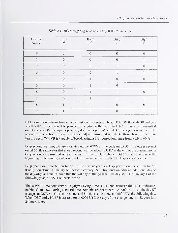
Chapter 2 - Technical Description
Table 2.4. BCD weighting scheme used by WWVB time code.
Decimal
numberBit 1 Bit 2 Bit 3
2'
Bit 42°
U (J 0 0 0
11 U
AU
AU 1
z Au AU
11
AU
-5
J Au AU 11
11
A nu 11
AU AU
5 0 1 0 1
6 0 1 1 0
7 0 1 1 1
8 1 0 0 0
9 1 0 0 1
UTl correction information is broadcast on two sets of bits. Bits 36 through 38 indicate
whether the correction will be positive or negative with respect to UTC. If ones are transmitted
on bits 36 and 38, the sign is positive; if a one is present on bit 37, the sign is negative. The
amount of correction (in tenths of a second) is transmitted on bits 40 through 43. Since four
bits are used, WWVB is capable of broadcasting a UTl correction range from -0.9 to +0.9s.
Leap second warning bits are indicated on the WWVB time code on bit 56. If a one is present
on bit 56, this indicates that a leap second will be added to UTC at the end of the current month
(leap seconds are inserted only at the end of June or December). Bit 56 is set to one near the
beginning of the month, and is set back to zero immediately after the leap second occurs.
Leap years are indicated on bit 55. If the current year is a leap year, a one is sent on bit 55,
usually sometime in January but before February 29. This ftinction adds an additional day to
the day-of-year counter, such that the last day of that year will be day 366. On January 1 of the
following year, bit 55 is set back to zero.
The WWVB time code carries Daylight Saving Time (DST) and standard time (ST) indicators
on bits 57 and 58. During standard time, both bits are set to zero. At 0000 UTC on the day STchanges to DST, bit 57 is set to a one, and bit 58 is set to a one at 0000 UTC the following day.
When DST ends, bit 57 is set to zero at 0000 UTC the day of the change, and bit 58 goes low
24 hours later.
61

NIST Time and Frequency Radio Stations: WWV, WWVH, and WWVB
WWVBTIME CODE FORMAT
— ON TIME POINT A
TIME FRAME 1 MINUTE(index count 1 second)
20 30 40
1 Ill IIIIIIIM 1 1 1 1 1 M 1 1 II IIIIIIIM IIMIMIIP1
|<-0.8 SECOND^2
-*-\*- 0.2 SECOND --|w|<- -f-l"!-*-
p-».||-«- 0.5 SECOND
^0.8 SECOND-*!
1
mvi rnirmnrrumirr rir™ui 1
C\Jt— 00 CO^CM"— 00 0000 CO'3-C
L MINUTES—^ HOURS—
I
DAYS-
1 PPM FRAME REFERENCE MARKERSBINARY CODED DECIMAL YEAR AND TIME-OF-YEAR correction
CODE WORD (31 bits)
6 PPM POSITION (IDENTIFIER MARKERS (Pq thru P5)
(reduced carrier 0.8 second duration plus 0.2 second duration pulse)
W - WEIGHTED CODE DIGIT (carrier restored in 0.5 second - binary one)
U - UNWEIGHTED CODE DIGIT (earner restored in 0.2 second - binary zero)
I y uFiiriiwrinnrruimruii'innmLQ CDQ
L J
UT1
SIGNUT1
UTC AT POINT A2001
258 DAYS18 HOURS42 MINUTES
UT1 AT POINT A2001
258 DAYS18 HOURS41 MINUTES59.3 SECONDS
LEAP SECOND WARNING BIT
LEAPYEAR INDICATOR BIT
0-=NON LEAPYEAR;r=LEAPYEAR
Figure 2. 15. WWVB time codeformat.
Standard time intervals are also broadcast on WWVB. The frame reference marker described
above indicates the beginning of a minute; tens of seconds are indicated by the position
markers. Individual seconds are indicated by counting the pulses.
3. Frequency and Power LevelWWVB broadcasts continuously at 60 kHz. Normal radiated power is 50 kW, with the
antennas operated in the normal dual antenna configuration. When in standby (single antenna)
configuration, WWVB radiates 27 kW.
4. Modes of OperationWWVB can operate in two broadcast modes: single antenna or dual antenna. The single
antenna mode consists of a the 60 kHz WWVB signal being broadcast from one antenna, with
the other antenna grounded. This mode has a normal radiated power level of about 27 kW, and
is used occasionally when maintenance or repairs are being performed on the other antenna
system.
62

Chapter 2 - Technical Description
WWVB is normally operated in dual antenna mode (see Figure 1.19). In this mode, two
transmitters are on the air, simultaneously broadcasting the same WWVB input signal. Onetransmitter feeds the north antenna, and another feeds the south antenna. The transmitters drive
the antennas at equal current levels.
5. Broadcast controlThe WWVB broadcast is controlled by the RF switch matrix and the control console. The switch
matrix allows any transmitter to be connected to either antenna or the dummy load, and the
console contains switching and monitoring equipment that enables the operator to activate or
deactivate the transmitters into these loads, and to monitor the power levels and operating status
of the transmitters.
LFT-1
LFT-3 -e
DUMMYLOAD
6. RF Switch Matrix
A simplified schematic representation of the RF switch matrix is shown in Figure 2.16. The
switch is rated for 50 kW average power, and is operated manually. The unit is a strip line
switch with three sets of RF busses on either side of a grounded vertical baseplate. Transmitter
and load connections are made with 3 1/8 in (79 mm) coaxial transmission line. The three
transmitters are connected to the rear busses, and the three loads are connected to the front set.
The busses are spaced
off the baseplate to J;}^.,. , . rrv ANTENNA ANTENNA
mamtam a 50 Qcharacteristicimpedance through the
switch. Connections
between thetransmitter and load
busses are made using
contacts mounted on
rams that pass through
holes in the baseplate.
When the rams are
manually pulled out to
the deselectedposition, the contacts
act to complete the
path to the adjacent
vertical and horizontal
rams. When a
transmitter is patched
into a particular load,
that ram is pushed in
to a locked, selected
position that interrupts
the path to adjacent
LFT-2
Figure 2. 16. RF switch matrixfor WWVB transmitters.
63

NIST Time and Frequency Radio Stations: WWV, WWVH, and WWVB
switches and connects the transmitter to the load. Interlock switches are also configured to track
the switch configurations; this information is sent to the control console.
7. Control ConsoleThe control console uses a programmable logic controller (PLC) that constantly monitors the
operating status of the broadcast.- The PLC is programmed to prevent operating modes that
would be unsafe to personnel or damaging to the equipment. For example, interlocks are
provided to prevent more than one transmitter operating into a single load, or to allow a
transmitter to operate without a load. Interlocks fitted to the access doors on the transmitters
and inside the helix houses prevent injury to personnel. The PLC also performs as part of the
automatic tuning system.
8. Automatic TuningUnlike the WWV antennas, which are single towers that have static operating characteristics, the
WWVB antennas are designed to move somewhat with wind or ice loads. When this happens,
the impedance they present to the transmitters changes with their movement. This causes the
reflected (reverse) power to increase, and the radiated (forward) power to decrease. To
compensate for this, automatic antenna tuning (autotune) systems have been installed. These
systems turn the variometers (variable inductors) located in each helix house to maintain the
optimal impedance match with the transmitters.
The autotune systems use a phase comparator located in the local control unit in each
transmitter. The comparator monitors the phase difference of current and voltage samples taken
from the output of the transmitter. When the antenna is properly tuned to the transmitter, the
current and voltage are essentially in phase. When the tuning changes due to antenna
movement, the voltage and current phase relationship changes. The comparator senses this
change, and sends a command for a change in variometer position to the PLC, which tunes the
variometer to correct the impedance mismatch. The autotune system also maintains the relative
phase of the broadcast signal.
9. TransmittersThe AN/FRT-72 transmitters are linear amplifiers, and the four power amplifier (PA) tubes are
configured for Class ABi operation. A block diagram of the transmitters is shown in Figure
2.17. The 2 V peak-to-peak WWVB signal is fed Irom the control console to the local control
unit in the transmitter. This unit interfaces the transmitter internal control circuits with the
remote console, by way of a microprocessor and communicafions bus, and also allows local
operation of the transmitter in certain configurations. The local control unit sends the low level
WWVB signal to the solid state driver amplifier, which raises the power of the signal to about 5
V peak-to-peak and sends it on to the four PA tubes.
The tubes operate in two pairs. Each pair is configured as a push-pull amplifier, and the outputs
are combined in a plate transformer. The transformer secondaries are combined in a
combiner/sampler unit, that is connected to the RF switch matrix using rigid transmission line.
Output voltage and current samples are sent to the transmitter local control unit, and fi-om there
64

Chapter 2 - Technical Description
UNEIN:
TOkVt
eOkHiWVW8SH3NALFROM
CONSOLE
HKW/7DRAND
CONmOLBUSTO CONSOLE
UNEIN:4S0v70kVi
POWERDISTRIBUTION
PLATEPOWERSUPPLY
TRANSMITTERLOCAL
CONTROL
lOkVDC
PLATEXFMR
J I OUTPUT'~ SAMPLES
lOkVDC
POWERDISTRIBUTION
PLATEPOWERSUPPLY
PIATEXFMR
RF COMBINERt SAMPLER
37 kWWWVB SIGNALTO SWITCHMATRIX
OUTPUT VOLTAGEAND CURREIfT SAMPLES
TO TRANSMITTERLOCAL CONTROL
Figure 2. 1 7. Block diagram ofWWVB transmitter.
to the console. Although the transmitters are rated at 50 kW forward power, they are normally
driven at about 37 kW in dual antenna mode, which achieves an effective radiated power of 50
kW. The transmitters are about 44 % efficient.
The transmitters contain overload circuits that will shut off the 10 kV DC plate power supply or
the RF input in case of equipment malfunctions or high reflected power levels. These overload
events could be caused by several factors, such as high wind gusts, lightning, or a defective tube
or other component. Often the events are short in duration and the transmitter can be safely
restored to normal operation in a few seconds. This is accomplished by an automatic overload
recycling system, which resets the overload relay and restores the plate power supply. The
system is set at three recycles; if after the third attempt an overload condition still exists, the
plate power supply is disabled. In the case of high wind gusts or lightning, the transmitter local
control unit monitors the reflected power levels and disconnects the drive to the transmitter if
these levels exceed a preset level. The drive is restored after a preset number of seconds; if the
abnormal condition persists after three tries, the drive is disabled.
10. Helix HousesThe two helix houses are where the on-line transmitters are connected to the antennas. They
contain components that match the 50 impedance of the transmitters to the much lower
impedance of the antennas. The matching circuits are primarily inductive to cancel the inherent
capacitance of the electrically small antennas.
65

NIST Time and Frequency Radio Stations: WWV, WWVH, and WWVB
Figure 2. 18. Interior view ofhelix house.
The helix houses are named for the large hehcal coil that was installed there as part of the
original WWVB and WWVL antenna matching equipment. When the station was upgraded, the
coils were removed and a variometer and other coupling components installed that were capable
of handling the higher power output of the newer transmitters. The two helix houses contain
identical components. A view of the interior can be seen in Figure 2.18.
A simplified schematic diagram of one of the WWVB helix houses is shown in Figure 2.19. A3 1/8 in (79 mm) flexible coaxial transmission line is run from the RF switch matrix output in
the transmitter building to each house, along with fiber optic and copper telemetry and control
cables, and line voltage cables. All conductors are run in a concrete-lined trench for protection.
The transmission line is 417 m in length to the north helix house, and 423 m long to the south
house.
At the helix house, the transmission line is terminated inside a fenced area in the building. The
cable is connected first to a "tee" network. Coupling inductors are installed in parallel with the
output of the tee; one coil is switched with an RF relay to change the impedance of the system
for single antenna operation. This is necessary because when both antennas are ungrounded, as
in dual mode, their characteristics change due to mutual coupling. In the normal dual antenna
operation mode, the relay is in the unpowered, normally open position.
66

Chapter 2 - Technical Description
ROOFBUSHING
SO OHMCOAXIALCABLE
TKANSUITTERBUILDING
TEE-NETWORK
J.
VARIOMETER
<:::>
FIBEROPTICAND COPPERTELEMETRYANDCOmPOL
CABLES<
SINGLE/ DUAL\
RELAY
HEUX HOUSE AND ANTENNATQEMETRY AND COMTFOL
StONM.
ANTENNAGROUNDINGswncH
VARIOMETERDRIVE
ANTENNASWITCHORfVE
Figure 2. 19. Simplified diagram ofWWVB helix house.
The antenna current is sampled by a current transformer, and sent to the control console in the
transmitter building via fiber optic cables. Another coil, mounted next to the variometer, is
used to supply phase and signal status information to the screen room.
The variometer is a physically large inductor consisting of a fixed horizontal winding called a
stator, with a smaller moveable winding rotor mounted inside on a vertical shaft. This rotor is
turned by means of a reversible motor installed at the base of the shaft, underneath the stator.
Telemetry and control circuits allow the variometer motor to be operated in either direction
automatically, which varies the inductance of the matching networks. In this way, the
autotuning system keeps the antenna at the optimal impedance during windy or icy conditions
that effect the impedance of the antenna.
The antenna grounding switch is mounted above the variometer, near the ceiling of the helix
house. It consists of two graphite spheres about 100 mm in diameter, one of which is fastened
to the input bus to the roof bushing. The other sphere is electrically grounded, and mounted on
the end of a spring-loaded telescoping shaft, which is operated by a wire rope connected to a
67

NIST Time and Frequency Radio Stations: WWV, WWVH, and WWVB
motor near the floor. When the ground command is given, the motor is switched on, unspooling
the cable and allowing the spring to drive the two spheres together. In the ungrounded position,
the distance between the spheres has been set to allow the open switch to function as an arc gap
for lightning protection.
Telemetry and control equipment is located outside the fenced area, where it is accessible while
the antenna is in use. Local controls are installed to allow the antenna ground switch and the
variometer drive to be actuated from the helix house.
The gate in the fence is equipped with a lock, the key to which is stored in a secure area.
Security measures are in place that require the antenna grounding switch to be actuated before
anyone can enter the fenced area. Also, the gate itself has an interlock switch that prevents the
connected transmitter from operating while the gate is open. This arrangement prevents the
antenna from being ungrounded or a connected transmitter from being activated while station
personnel are inside the fenced area.
11. AntennasThe two WWVB antennas are monopoles. Although they are physically much larger than the
WWV antennas, they are electrically quite small with respect to the wavelength of 60 kHz.
Ideally, an efficient antenna must have a radiating element of at least one-quarter wavelength.
However, at 60 kHz the wavelength is about 5000 m, meaning that a quarter-wavelength
antenna would be about 1250 m tall, which is impractical to build. One way of constructing
antennas for the low frequency band involves making the vertical element as high as possible,
and adding electrical "length" horizontally at the top of the radiating element. This technique is
known as top loading. The loading element is sometimes called a top hat or capacitance hat. As
described in Chapter 1, the two WWVB antennas each consist of a top hat, downlead, and
ground plane. The height of the towers from which the antenna is suspended is 122 m, with the
maximum distance between towers of 573 m. The north antenna coordinates (Figure 1 .4) are
40° 40' 51.308" N, 105° 03' 00.011" W; the south antenna coordinates are 40° 40' 28.298" N,
105° 02' 39.531" W. The distance between the downleads is 866 m.
Although the WWVB antennas were built in the early 1960's, they have both been overhauled
and upgraded in the late 1990's to accommodate the higher power broadcast allowed by the
installation of the AN/FRT-72 transmitters. After the upgrades, extensive engineering studies
were undertaken to determine the operating characteristics of these antennas [42, 43]. The
effective or electrical height of each antenna was determined to be approximately 86 m. Asshown in Table 2.5, the resistance of the antennas is much lower than that of the perfectly sized
WWV antennas, due to the size of the radiating element, which is extremely short whencompared with the wavelength. Whereas the WWV antennas can be built such that their gross
resistance {Rg) is very nearly 50 Q, Rg for the WWVB antennas is less than 1 Q when operated
in single mode. In dual mode, the two antennas interact and mutual resistance becomes a factor.
68

Chapter 2 - Technical Description
Table 2.5. Resistance and efficiency ofWWVB antennas.
Single Dual
North South North South Mutual
Gross resistance 0.859 0.825 1.264 1.151 0.366
Rg (ohms)
Radiation 0.464 0.464 0.104 0.104 0.360
resistance
Rr (ohms)
Radiation
efficiency 56.30 % 54.00 % 68.80 %
When operated in single antenna mode, the north antenna was found to be 56 % efficient, and
the south antenna 54 % efficient. However, when operated in dual antenna mode, the two
antennas effectively become an array, which has an efficiency of nearly 69 %. In the world of
LF broadcasting, this is an impressive figure, and it allows 50 kW to be radiated with only
about 37 kW input to both antennas. These conservative transmitter operating parameters
increase the reliability of the signal, since the transmitters are not operating near their limits
and are thus able to tolerate higher levels of reflected power and still stay on the air. Anadditional bonus is the increased life of tubes and other broadcast components.
The intrinsic bandwidth of the antennas was found to be 310 Hz for the north and 263 Hz for
the south [44]. The combined bandwidth has not been measured but has been calculated to be
about 411 Hz. When loaded by the transmitter, this increases by a factor of about 1.5 to a
estimated bandwidth of slightly over 600 Hz.
The ground side of the antenna matching circuit is connected to the antenna ground plane.
Each of the approximately 300 tinned, copper-braided wires in the ground plane is about 3 mmin diameter. These wires extend radially out trom the helix house foundation, where they are
brazed to a buried peripheral 13 mm copper cable. This cable is soldered to copper straps
which extend out of the concrete foundation at 2 m intervals; the straps are incorporated into a
network of copper straps within the foundation, and connect to stubs that protrude from the
floor at several locations within the helix house, where the connection to the antenna
equipment is made.
One reason the Fort Collins site was originally chosen was the high soil conductivity, measured
at 14.5 millimhos per meter to a depth of 0.45 m. Highly conductive soil means that ground
losses from a transmitting antenna are low, improving the antenna's efficiency [44].
12. Monitoring and Alarm SystemsMonitoring and alarm systems for WWVB are combined with the systems for WWV and are
described in that section.
69

NIST Time and Frequency Radio Stations: WWV, WWVH, and WWVB
D. Technical Description of WWVHThe design and configuration of Radio Station WWVH in Hawaii bears many similarities to that
of WWV. The main differences are found in the broadcast equipment, which is often of
different manufacture, and in the physical layout of the facility and equipment.
1. Timing SystemThe fi-equencies broadcast by WWVH originate in the main screen room. Three independent
time and frequency generation systems operate continuously, each in a separate equipment rack.
One of the systems or racks is selected as the on line unit, or site master clock. Outputs from
each rack are sent to monitoring and data logging equipment, and to a controller that sends the
RP output from the selected rack to the transmitters.
Each time and frequency generation system is made up of a frequency standard, a frequency
divider/distribution amplifier, a time code generator (TCG), and monitoring and ancillary
outputs. Normally, all the frequency standards are commercially available cesium oscillators.
A rubidium oscillator is sometimes used as a backup in case of a failure of one of the cesium
oscillators. Figure 2.20 shows a simplified block diagram of the WWVH time and frequency
^ To Aterni Eqi^ptrmt
/tl/^HHtnd Baat Stcurity Offic*
OUTPUT
FREQUENCYSTANDARD
5 MHz
>\
FREQ. DIVTOER
ANDDISTRBUnONAMPUFIER
lUHz
WWVHSIGNAL
: GENERATIONSYSTEMRACK A(1 OF 3)
1MHz
SUHz
SUHz
WWVHVMECODE
TIME CODEGENERATOR
1 MHz - 1 PPSOMDER
STAVONREFERENCE
1PPS
WWVHFREa
ANDVUECODE
5 MHzFROMRACKSBiC
VMECODEFROM -
RACKSBiC
SCREENROOM
CONTROUJERIMT
FREQUENCYANDVME -
CODE FROMRACKS BiC
SthcMSMHztoRFMuHpSfUnitnd ModiMora
VWI/VHThmCcdtto Mt loggf
WWVHTIME CODE
AND FREQUENCYCOMPARATOR
fo
Tim* Inluvtl
Counl»^D»lak>gg»r
toFMAS
Figure 2.20. Simplified diagram ofJ^'WVH time andfrequency generation system.
70

Chapter 2 - Technical Description
generation system and its interconnection with monitoring and control equipment. The 5 MHzoutput from the frequency standard is sent to a divider/distribution ampUfier, which distributes
the signal to the TCG, the FMAS system, and a 1 MHz to 1 PPS divider.
2. Broadcast FormatThe WWVH broadcast format is very similar to that of WWV. It contains standard carrier
frequencies, standard audio frequencies, time intervals, voice time announcements, an identical
BCD time code, and official announcements. All frequencies and tones are derived from the
site master clock.
The four WWVH carrier frequencies (2.5, 5, 10, and 15 MHz) serve as standard reference
frequencies. All audible frequencies and tones are generated in the TCGs. These units are
nearly identical to the WWV TCGs in construction, and differ only in their internal
programming, and in that they output a higher frequency (1200 Hz vs. 1000 Hz) seconds and
minutes tone. Voice time announcements and the station identification message are stored in
the TCG, using a pre-recorded female voice. Official announcements are stored in a separate
voice storage system, that is accessed via telephone by the announcing agencies. Figure 2.21 is
a simplified block diagram of the WWVH audio signal generation and distribution system.
SCREEN ROOMCONTROLLER
2 kHzALARMTONE
I
SUHzFROM
FREQUENCYSTANDARD A
OFFICIAL
ANNOUNCEMENTS
SUHzFROM
FREQUENCYSTANDARDS
OFFICIAL
ANNOUNCEMENTS
TIME CODEGENERATOR
A
TftCCODEGENERATOR
B
5 MHzIN
WWVHAUDIOSIGNAL
PRIMARYTRANSMITTERMODULATOR
TIME CODEGENERATOR
C
OFFICIAL
ANNOUNCEMENTS
ALDIOSELECTOR
SELECTEDWWVHAUDIO
I .
WWVHAUDIOSIGNAL
AUDIODIST.
AMP
Modulated wm/HSignal to 15 MHzPrimary Transmitter
WWVHAudio Signal
to 5, 10, 15 MHzPrimary Transmitters
SMHzIN
STANTDBYTRANSMrTTERMODULATOR
Modulated
vmVH signal
to all standby
transmitters
vmVH Audio Signal
to Telephone
Time-of-Day
Equipment
Figure 2.21. Simplified diagram ofWWVH audio signal generation system.
71

NIST Time and Frequency Radio Stations: WWV, WWVH, and WWVB
a) Standard Carrier Frequencies
WWVH standard carrier frequencies are derived from the site master clock. Figure 2.22 shows
a simpHfied diagram of the carrier frequency generation system. A 5 MHz signal is sent from
each time and frequency generation rack to the screen room controller, which sends the selected
signal on to an RP multiplier unit, which outputs a 5, 10, and 15 MHz signal that is sent directly
to the primary transmitters for those frequencies. The selected 5 MHz output from the controller
is also sent to the modulator for the 2.5 MHz primary transmitter, as well as the standby
transmitter modulator. These units create the composite audio signal for these transmitters.
b) Voice Time AnnouncementsThe WWVH voice time announcements are broadcast once each minute. They are made using a
female voice, and begin about 15 s before the beginning of the minute. The announcements last
about 7 s. For 1452 UTC, the announcement would read:
"At the tone, fourteen hours, fifty two minutes, coordinated universal time."
FREQUENCYSTANDARD
TO/EANDFREQUENCYGENERATIONSYSTEM A(SELECTED)
FREQUENCYSTANDARD
TIME ANDFREQUENCYGENERATIONSYSTHvlB
FREQUENCYSTANDARD
TIME ANDFREQUENCYGENERATIONSYSTEM C
5 MHz FREQ. DMDERAND
DISTRIBUTION
AMPUFIER
SHHz
TIME CODEOENERATOR
5MWz FREQ. DMDERAND
DISTRIBUTION
AMPURER
TBtlECODEGENERATOR
5 MHz FREQ. DMDERAND
DISTRBUTIONAMPLffER
TIME CODEGENERATOR
5 MHz
SMHz
5 MHz
iL
Cortmlttr
A
Corimtltr
A
RF MULTIPUERUNIT
^ cmhrfnqutncltato 6, 10. IS MHz
w tmttinMtta
Audio
75 mzPRIMARY
TRANSMfTTERMODULATOR
UodiModWWVHaIgn*!(0 2.6 MHztnnmilor
2 kHz I
•term'
ton*Audio
kpul
STANDBYTRANSMTTTERMODULATOR
UoduUttdWmHalgntIf0 it et*ndby
tmnamlttm
Figure 2.21. Simplified diagram ofWWVH carrierfrequency generation system.
72

Chapter 2 - Technical Description
The announcement is followed by about 8 seconds of ticks without a tone, then a short 1200 Hztone indicates the top of the minute. A station identification message is broadcast twice each
hour. The station ID reads as follows:
"National Institute of Standards and Technology Time: this is Radio Station
WWVH, Kauai, Hawaii, broadcasting on internationally allocated standard
carrier frequencies of two-point-five, five, ten, and fifteen megahertz,
providing time of day, standard time interval and other related information.
Inquiries regarding these transmissions may be directed to the National
Institute ofStandards and Technology, Radio Station WWVH, Post Office Box417, Kekaha, Hawaii, 96752. Aloha.
"
The WWVH station ID announcement lasts for about 37 seconds, and is broadcast during the
minute that precedes the tone marking the beginning or midpoint of the hour. For example, the
announcement runs at 1059 UTC and 1129 UTC. It is stored in its entirety in read-only
memory in the TCGs.
c) Standard Time Intervals
Like WWV, standard time intervals broadcast on WWVH are indicated by various tones of
various lengths. Intervals of seconds, ten seconds, minutes, hours, and days are all part of the
broadcast. The time intervals are indicated as follows:
• Seconds: bursts of 1200 Hz tone; most are 5 ms long, which simulates the ticking of a
clock. These ticks are omitted on the 29"^ and 59"^ seconds. The second that begins each
minute is indicated by a longer tone.
• Ten Seconds: indicated on BCD time code.
• Minutes: 800 ms burst of 1200 Hz tone at the beginning of every minute except the
beginning of the hour.
• Hours: 800 ms burst of 1 500 Hz tone at the beginning of every hour. Also, the 440 Hz tone
is broadcast on minute 1 of each hour, except for the first hour of each day.
• Days: the 440 Hz tone described above is omitted during the first hour of each day.
d) Standard Audio FrequenciesWWVH also broadcasts standard audio frequencies during most minutes of every hour. Figure
2.23 illustrates the WWVH audio broadcast format. Audio tones of 500 Hz and 600 Hz are
broadcast on alternating minutes, and a 440 Hz tone is broadcast once each hour, except the
first hour of the day. The tones are normally broadcast in the reverse order of WWV; for
example, if a 500 Hz tone is being broadcast on WWV on a particular minute, a 600 Hz tone is
broadcast on WWVH on that same minute. The 440 Hz tone is broadcast on minute 2 on
73
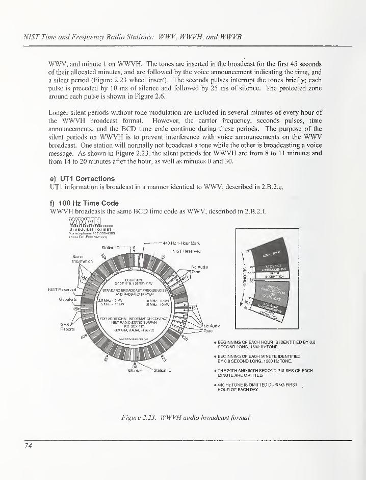
NIST Time and Frequency Radio Stations: WWV, WWVH, and WWVB
WWV, and minute 1 on WWVH. The tones are inserted in the broadcast for the first 45 seconds
of their allocated minutes, and are followed by the voice announcement indicating the time, and
a silent period (Figure 2.23 wheel insert). The seconds pulses interrupt the tones briefly; each
pulse is preceded by 10 ms of silence and followed by 25 ms of silence. The protected zone
around each pulse is shown in Figure 2.6.
Longer silent periods without tone modulation are included in several minutes of every hour of
the WWVH broadcast format. However, the carrier frequency, seconds pulses, time
announcements, and the BCD time code continue during these periods. The purpose of the
silent periods on WWVH is to prevent interference with voice announcements on the WWVbroadcast. One station will normally not broadcast a tone while the other is broadcasting a voice
message. As shown in Figure 2.23, the silent periods for WWVH are from 8 to 11 minutes and
firom 14 to 20 minutes after the hour, as well as minutes 0 and 30.
e) UT1 Corrections
UTl information is broadcast in a manner identical to WWV, described in 2.B.2.e.
f) 100 Hz Time CodeWWVH broadcasts the same BCD time code as WWV, described in 2.B.2.f
Broadcast FormatVia telephone (808)335-4363(NotaToll-Free Number)
NIST Reserved
Geoalerts
440 Hz 1- Hour Mark
No Audio
GPS/^Reports
No Audio
Tone
• BEGINNING OF EACH HOUR IS IDENTIFIED BY 0.8
SECOND LONG, 1500 Hz TONE.
• BEGINNING OF EACH MINUTE IDENTIFIEDBY 0.8 SECOND LONG, 1200 Hz TONE.
Minutes Station ID • THE 29TH AND 59TH SECOND PULSES OF EACHMINUTE ARE OMITTED.
• 440 Hz TONE IS OMITTED DURING FIRSTHOUR OF EACH DAY
Figure 2.23. WWVH audio broadcastformat.
74

Chapter 2 - Technical Description
g) Official AnnouncementsWWVH also carries official announcements by U.S. Government agencies. Theannouncements are of a public service nature and are limited to 45 seconds per segment. Morethan one segment may be used by a particular agency. Announcement allocations as of this
writing can be seen in Figure 2.23 and are listed in Table 2.6. For more information about the
content of the announcements, see NIST Special Publication 432 [38], or contact the
sponsoring agency.
Table 2. 6. WWVH official announcements.
Minute Message Sponsor Web Site
43,44 GPS satellite status
U.S. Coast Guard
Navigation Center
www.navcen.uscg.gov/
RPS/
45 Geophysical alerts
NOAA Space
Environment Center www.sec.noaa.gov
48
West Pacific high seas storm
warning National Weather Service www.nws.noaa.gov
49
East Pacific high seas storm
warning National Weather Service www.nws.noaa.gov
50
South Pacific high seas
storm warning National Weather Service www.nws.noaa.gov
51
North Pacific high seas
storm warning National Weather Service www.nws.noaa.gov
52
Other Pacific storm
warnings (when necessary) National Weather Service www.nws.noaa.gov
In addition to the announcements shown above, NIST reserves minutes 3 and 47 of the WWVHbroadcast for occasional special announcements. These segments are used to relate
information of interest to users of the time and frequency broadcasts, such as user surveys or
changes to the broadcast. When no announcement is present, a 500 Hz tone is usually
broadcast.
The WWVH voice storage system was designed and built by station personnel, and is
connected to an incoming telephone line dedicated to that purpose. An alternate telephone line
is available if the primary line goes down. Users dial into the voice storage system and leave
the messages to be broadcast on an allocated channel in that device. At the appropriate time,
the time code generators play that message as part of the composite audio signal sent to the
transmitters.
Ii) Modulation Levels and Spectrum Allocation
Described earlier; see 2.B.2.h.
75
NIST Time and Frequency Radio Stations: WWV, WWVH, and WWVB
i) WWVH Signal Monitoring
As with WWV, the WWVH signal is monitored at several points: comparator and control
circuits, manual timing comparisons, and FMAS. The WWVH system includes a time code and
frequency comparator, identical to the unit at WWV, described in 2.B.2.i. This unit monitors
the accuracy of the WWVH timing and the stability of the frequency standards.
The WWVH screen room controller communicates with the time code and frequency
comparator; if an alarm is sensed the controller switches racks and sends an alarm signal to the
WWVH alarm panel.
The WWVH signal is also monitored by manual comparisons. Daily comparisons are made
with UTC(NIST) in Boulder, using the GPS common-view technique. The TCG 1 PPS outputs
are compared against each other and against a 1 PPS output derived from the frequency
standards. Corrections to the frequency standards and time code generators are entered using a
nanosecond stepping unit, when required.
The stability of the WWVH frequency standards is monitored by phase comparisons of their
outputs. A 1 00 kHz output from each standard is routed to phase error detection equipment, and
the result is sent to a Honeywell (DPR3000) strip chart recorder. The configuration allows
comparisons of all standards against each other. The recorder also accepts phase and amplitude
inputs from a 60 kHz WWVB receiver, providing a valuable remote monitoring service for that
station. A PC is used to download the data from the recorder; it is archived on CD-R disks. The
FMAS system [37] also tracks the stability of the WWVH standards.
A microprocessor-controlled time interval counter, designed and built by NIST, is installed in
the WWVH screen room. This unit accepts 1 PPS inputs from each frequency standard and
TCG, and logs the difference hourly. The data can be used to troubleshoot and isolate problems
in the timing systems. A computer is connected to the counter and is used to archive the data.
3. Frequencies and Power LevelsWWVH broadcasts continuously on 2.5 MHz, 5 MHz, 10 MHz, and 15 MHz. Normal radiated
power is 10 kW on 5, 10, and 15 MHz, and 5 kW on 2.5 MHz. When standby transmitters are
operating, radiated power is 5 kW for all frequencies. Table 1.3 shows the transmitter
designations and configuration.
New transmitters made by AEL Corporation were installed when WWVH was moved from
Maui to Kauai in 1971. These units were linear amplifiers, with the final amplifier tube
operated class ABi. The final amplifier is a (4CX50,000J) high power vapor-cooled tube, which
has an overall efficiency of about 20 %. A simplified block diagram of a modified AELtransmitter can be seen in Figure 2.24. The low-level RF WWVH signal is sent from the
modulator to the transmitters, which amplify it through three stages to 5 kW at the output of the
transmitter. After the Elcom-Bauer transmitters were installed for the 5, 10 and 15 MHzbroadcasts in 1983, the 2.5 MHz primary and standby transmitters were refitted with smaller,
air-cooled final amplifier tubes that raised their efficiency to about 33 %.
76

Chapter 2 - Technical Description
MODULATEDWWVH -
SIGNAL
20SV3 PHASE
*/- 180 VDC
DRIVERAMP
FINAL
PA
3000 VDC
MAIN MAINPOWER PLATEDIST. SUPPLY
7500 VDC
5MVTO
ANTENNA
The Elcom-Bauer
transmitters have a
final ampUfier
stage operated class
C, with an overall
efficiency of about
45 %. A simplified
block diagram of
this transmitter is
shown in Figure
2.25. The Elcom-
Bauer transmitter
receives the carrier
fi-equency from an
RP multiplier
circuit, and the
WWVH composite audio signal from the selected TCG. The carrier is amplified by the solid-
state RF exciter and driver amplifiers, then fed to the unbiased grid of the 4CX15,000A power
tube. The audio signal fi-om the selected TCG is amplified separately using two solid-state
amplifiers, then fed to
dual 4CX5,000A power
tubes configured as a
Class ABi push-pull
amplifier. The power
tubes, together with a
choke and modulation
transformer, create the
10 kW modulated
signal.
Figure 2.24. Simplified block diagram ofmodified AEL transmitter.
RFW.5, (0 -
OR)5 MHz
UNEIN:208V
3 PHASE
WWVHAUaOIN
RFEXCITER
POWERaSTRBUnON
PLATEPOWERSUPPLY
AUDIOPUT
PROCESSOR
MOOU.ATORDRIVER
AMPUFER
10 KWlo Bnlenna
4. WWVHAntennasWWVH antenna data is
listed in Table 2.7.
Each primary phased-
array antenna for the 5,
10, and 15 MHzbroadcasts consists of
dipole towers spaced
one quarter-wavelength apart, aligned to a bearing of 260° east of true north. A recent antenna
modeling study done by the WWVH staff revealed that the antennas have a cardioid radiation
pattern with a 20 dB fi-ont-to-back ratio; the maximum gain of the signal is to the west. Each
antenna is equipped with a double-stub tuning network installed between the bases of the
towers, which precisely matches the antenna impedance to the 50 Q. output impedance of the
Figure 2.25. Simplified block diagram ofElcom-Bauer transmitter.
77

NIST Time and Frequency Radio Stations: WWV, WWVH, and WWVB
Table 2. 7. WWVH antenna data.
Frequency
(MHz)Use Height
(m)
Type Latitude Longitude
r 1 llllal y 70 QZ. -7." quarter-wave base-
fed monopole1 SQ" 4S' S9 4" W
2.5 Standby 22.9
base-fed monopole
with adjustable
matching
equipment
21° 59' 19.2" N 159° 45' 46.2" W
Primarv 36.3phased array, two
half-wave dipoles21° 59' 10.8" N 159° 45' 44.8" W
10.0 Primary 18.3phased array, two
half-wave dipoles21° 59' 18.2"N 159° 45' 51.3" W
15.0 Primary 12.2phased array, two
half-wave dipoles21° 59' 15.3" N 159° 45' 50.0" W
15.0 Standby 5.5
phased array, two
quarter-wave
base-fed mono-
poles (prototype)
21° 59' 23.9" N 159° 45' 58.03" W
Broadband
#1Standby 16.5
base-fed monopole
with adjustable
matching
equipment
21° 59' 26.12" N 159° 45' 56.47" W
Broadband
#2Standby 16.5
base-fed monopole
with adjustable
matching
equipment
21° 59' 30.22" N 159° 45' 59.53" W
transmitters. The output of the tuning network is directly connected to the rear (easternmost)
tower, but an additional length of transmission line shifts the phase of the signal 90° to the
forward (westernmost) tower, which causes the cardioid effect.
A U. S. Navy engineering report was prepared on the current state of the WWVH antennas in
1999. Figure 2.26 shows the radiation of an idealized 5 MHz phased array antenna obtained
from this report. The modeled antenna is similar (but not identical) to the WWVH antenna, so
Figure 2.26 should be considered an approximation of the actual radiation pattern.
The omnidirectional antennas for the 2.5 MHz primary broadcast, the 2.5 MHz standby antenna,
and two broadband antennas (normally configured for the 5 and 10 MHz broadcasts) are all
base-fed monopoles made of fiberglass, as described in Chapter 1 . The matching equipment for
all standby antennas is manually adjustable for any frequency broadcast by WWVH, although
the 2.5 MHz broadcast would normally be broadcast only on the taller 2.5 MHz standby
antenna. All standby antennas are rated for 10 kW; the radiation pattern for the monopole
antennas is similar to that of the WWV half-wave dipole antennas (Figure 2.10) [40].
78

Chapter 2 - Technical Description
0
180
Figure 2.26. Approximation ofradiation patternfrom 5 MHz phased array antenna.
5. WWVH Broadcast Monitoring and Alarm SystemsWWVH is manned during normal working hours. Automated systems are installed to monitor
the timing, broadcast, and other equipment. WWVH has three independent alarm and
monitoring systems.
Transmitter status is monitored by an RF carrier/audio detection system similar in principle to
the one installed at WWV. The system senses a sample from each on-air transmitter and
demodulates the signal to the carrier and audio component. A 1200 Hz filter is applied to the
audio portion and a missing-pulse detector circuit is used to detect the 1 pps tick. If the carrier
or tick is not detected, the primary transmitter is turned off and the standby transmitter for that
frequency is activated. If an RF sample is not detected from the standby antenna, an alarm is
sent to the WWVH Alarm Panel.
All major alarms are monitored by the WWVH Alarm Panel. Tlie system monitors fransmitter
failure, high/low screen and transmitter temperatures, TCG and screen room controller failure.
79

NIST Time and Frequency Radio Stations: WWV, WWVH, and WWVB
status of the incoming electrical power, and the fUel level in the standby generator day tank. If a
major alarm is not resolved in 5 minutes, signals are sent to the automatic dialing system, naval
base security office and an off-site radio receivers.
The automatic dialing system dials the phones and pagers of station personnel in a
predetermined order. When the call is answered, a coded signal is heard that indicates a specific
problem. An alarm is also sent to the naval base security office, which also monitors fire and
security alarm systems.
Another alarm system operates in parallel with the two described above. It is independent of
the telephone system and has been used exclusively after the hurricanes in 1982 and 1992. In
the event of one of the alarm conditions mentioned earlier, an audio tone of about 2 kHz is
placed on the 2.5 MHz broadcast for the first 45 s of every minute (the tone is not derived from
the site master clock and is intended for alarm purposes only). The tone is removed during the
time-of-day voice announcement. Each staff technician and the station engineer has a modified
WWV/WWVH receiver which "listens" for the 2 kHz tone. When the tone is detected, a light
on the receiver is activated. The receiver also has a loop antenna to null the WWV broadcast. In
case of a problem with the 2.5 MHz broadcast, the receiver notes its absence and another light is
turned on. The indicator lights will remain in the on condition until manually reset by the user.
The 2 kHz tone is removed from the 2.5 MHz broadcast 20 minutes after the alarm is first
indicated.
A data logging system, consisting of a programmable microcontroller circuit and PC, is used to
record events occurring at the station. The data logging circuit continuously monitors the status
of each transmitter and logs any change of state, and the duration of that change. It also
monitors the "silent periods" in the broadcast, and the status of the equipment alarm panel and
security alarm. The data is time tagged on the PC and archived as a text file. The PC clock is
synchronized to UTC using the Automated Computer Time Service (ACTS) [36].
The IRIG-H code (described in 2.D.2.f) from the TCG is also monitored using a programmable
microcontroller circuit and PC. The pulse width modulated signal is translated to a 60 character
string of "1", "0" and "P" then stored to the PC. If necessary, the archived data can be used to
determine whether a customer's radio controlled clock is correctly decoding the broadcasted
signal. All monitoring, logging, and alarm systems discussed above were designed and built by
station personnel.
6. Commercial Electric Power MonitoringThe status of the incoming 208 V AC electric power is monitored and logged by a three-phase
voltage disturbance analyzer made by Powertronics (PQR2020). The system measures nine
types of disturbances (frequency, voltage and noise) and can log 6000 events in nonvolatile
RAM. When necessary the data is downloaded to a PC for analysis and archived on disk.
80

Chapter 2 - Technical Description
7. UPS MonitorsThe Powerware (9170+) uninterruptible power supply (UPS) is a double conversion unit with
near zero switching time. It is a true on-line unit used to protect the sensitive electronic
equipment in both screen rooms. The unit is equipped with computerized event and alarm logs
that document any major disturbance in the electrical power. The unit has two independent
power supplies, giving it built-in redundancy if one power supply fails.
E. Telephone Time-of-Day ServiceNIST radio stations WWV and WWVH both offer a telephone-time-of-day service (TTDS)
where callers can hear an audio simulcast of the radio broadcast by telephone. This section
describes how this service works.
1. WWV Telephone Time-of-Day ServiceSince 1971, the WWV audio signal has been available by telephone by dialing 303-499-71 1 1
.
The system uses components or services located at the local telephone company, at the NISTlaboratories in Boulder, and at WWV and WWVB.
Customers dialing 303-499-7111 are connected to a call forwarding system at the telephone
company central office in the Boulder area, where calls are immediately forwarded on a
dedicated channel to the Boulder labs private branch exchange (PBX) system. The Boulder
PBX is connected with a similar WWV/WWVB PBX via a Tl voice/data connection; 15
channels of the Tl are dedicated to the TTDS. At the Boulder PBX, incoming calls are
converted to digital format, placed in a queue or "hunt group," and routed to the next available
channel of the Tl. At the station PBX, the calls are demodulated and sent to one of five
commercial call screening units. These devices are normally found at offices or businesses to
route callers to various extensions, and are sometimes referred to as a "phone tree." In that
application, the caller would normally hear a prerecorded greeting, followed by a list of options
or extensions that could be accessed. After making a selection, the caller would hear music
while on hold, unfil the extension was rung. However, in the TTDS application, no greefing is
played. The caller is immediately placed on hold, and instead of music, the caller hears the
audio signal from the on-air WWV time code generator. The screening unit disconnects the
call after a preset fime, normally 3 minutes. The length of call can be shortened, if necessary,
to accommodate more calls.
The TTDS system can handle up to 15 incoming calls simultaneously. Although the call
forwarding system cannot connect two calls arriving at the same instant, the transfer rate is
very rapid and is able to process traffic in a way that is transparent to the user. Once a call is
answered by the screening unit, that channel is active for the fiill 3 minutes even if the caller
hangs up beforehand. Therefore, the capacity of the system is 300 calls per hour (20 calls per
hour X 15 channels). A simplified diagram of the WWV TTDS system is provided in Figure
2.27.
As of this writing, Qwest Communications, Inc. provides local telephone service to the Boulder
labs, and owns and maintains the TTDS call forwarding system. Qwest also provides the Tl
81

NIST Time and Frequency Radio Stations: WWV, WWVH, and WWVB
service between Boulder and the station. The PBX at the Boulder labs is a Nortel Meridian
system, as is the PBX at WWV/WWVB. The call screening units are made by Interalia, Inc,
and are located next to the station PBX in the WWVB building.
TELEPHONECOMPANY
CALL FORWARDING
BOULDER LABSD«3(TAL
PRfVATEBRANCHEXCHANGE
(PBX) SYSTEM
INCOMINGm-499-7111
CALLS
ISCHANNELSOFT1
3UNSSPER
SCREENING UNIT
WWV AUDIOFROMSELBDTS}
TCO
VWWWWWBDtGITAL
PBX SYSTEM
CALL SCREENINGLMT
(1 OF 5)
DEDICATEDCALL TRANSFER
CHANNEL
12UNBSTOOTHER CALLSCREENING
UNITS
CALLSCREEhBNGLMT
CAU-SCRffiNWG
Figure 2.27. Block diagram ofWWV Telephone Time-of-Day System.
2. WWVH Telephone Time-of-Day ServiceThe WWVH Telephone Time-of-Day service was initiated in April 1973 and designed and built
by station staff. A caller dials 808-335-4363 and is connected to the WWVH audio signal. The
system is capable of handling a maximum of 480 calls per day.
82

Chapter 3 - Operational Procedures
Chapter 3
Operational Procedures
This section describes the operational procedures of the NIST radio stations. These procedures
must be performed to keep the station running smoothly, and to control the quality of the
broadcast signal. It also discusses how failures at each station are reported and addressed.
A. Hardware Maintenance
1. Transmitters and Broadcast EquipmentThe NIST radio stations' transmitting equipment requires frequent maintenance to keep it
operating smoothly. High voltage and RF circuits in the transmitters and antenna gear have
specific requirements for cleanliness, grounding, and general upkeep not found in other
electrical gear.
Each piece of broadcast equipment is subject to routine periodic maintenance. For the
transmitters in all stations, this involves taking the unit off line and bringing up a standby
transmitter to take over the broadcast during the maintenance period. A transmitter will be
disconnected from electrical power and all tubes and readily detachable components removed.
The entire transmitter is cleaned and inspected for burned, worn, or broken components. Parts
are lubricated, serviced, or replaced as required, and the transmitter is reassembled and tested
in a dummy load or on the air before being placed back in service. The maintenance interval
varies with the stations; at WWVH, the corrosive effects of the salt air from the nearby ocean,
coupled with high relative humidity require bimonthly maintenance routines for the primary
transmitters; the dry air and semi-arid climate around Fort Collins, as well as the fact that
WWV transmitter intake air is well filtered allows a six month maintenance interval.
However, the WWVB LF transmitters use a much higher volume of cooling air than the HFtransmitters, and their higher operating voltages require a bimonthly maintenance cycle.
Standby transmitters at both HF stations are usually subject to an annual maintenance interval;
at WWYB, all the transmitters are identical, and are rotated into service as required.
Transmitter matching equipment also requires periodic cleaning and inspection. At WWVB,the matching equipment resides in two three-story helix houses, with coils and transformers
that operate at high voltages and currents. Maintenance is performed semi-annually. Surface
areas are cleaned with laboratory alcohol and compressed air, electrical connections are
checked for tightness, and the variometer drive systems are lubricated. At WWVH, the
antenna matching equipment is mounted in weatherproof boxes at the base of each fiberglass
whip, and is inspected bi-monthly.
Antenna maintenance is also performed periodically. At WWV, the climate is very kind to
electrical connecfions and metal surfaces; maintenance consists of semi-annual visual and
83

NIST Time and Frequency Radio Stations: WWV, WWVH, and WWVB
mechanical inspections of hardware and connections, usually from the ground. Light bulbs
must be changed annually in the WWVB towers and the 2.5 MHz antenna; this is performed by
contractors. WWVB antenna maintenance is much more involved; it involves deploying four
gasoline powered generators to electric winch motors at the base of each tower, and lowering
the antenna to the ground. The connections are then inspected and repaired as required.
At WWVH, the steel antenna structures require a rigorous maintenance routine, due to the
corrosive effect of the salt air. The tower hardware and RF connections are inspected bi-
weekly and repaired as necessary, and the towers are painted every two years. The fiberglass
towers were installed beginning in 2001, and require periodic painting. Historically, station
staff have performed these ftinctions.
2. Timing EquipmentTiming equipment at the radio stations requires minimal maintenance; the equipment is housed
in air-conditioned screen rooms, and the incoming supply voltage to the equipment is
conditioned by UPS units to minimize disturbances and potential damage to the sensitive
equipment. The frequency standards, time code generators and distribution equipment are all
monitored continuously for errors or long term drifts.
B. Facilities IViaintenanceThe screen rooms have redundant air conditioning systems, which are cycled periodically to
verify their operation. Standby generator engines are run weekly, and a load test is performed
quarterly, where the transmitters and all building loads are placed on the generator for at least
one hour.
The remote location of the NIST Radio Stations relative to the Boulder labs requires station
personnel to take on a number of other tasks normally associated with support staff. Routine
tasks are performed on buildings, roads, antenna fields, air conditioning and ventilation
systems, lighting, air compressors, standby generators, electrical wiring and power distribution
systems, and portable gasoline powered generators.
More involved facilities maintenance projects and upgrades are handled by the NISTEngineering, Maintenance, Safety and Support Division (EMSS) and/or contractors. Recent
major upgrades to station electrical and air conditioning systems have been performed or
funded by EMSS. Facilities maintenance requirements such as servicing the standby
generators semi-annually are funded by EMSS.
84

Chapter 3 - Operational Procedures
C. Scheduled TasksSchedules of the various tasks performed by personnel at the radio stations are shown below.
All aspects of station operations and procedures including maintenance, repairs, service, etc.
are included in the list.
1. WWV Task Lists
Daily Tasks
• Check status of site master clock vs. UTC(NIST) via GPS common-view method.
• Complete daily log and data sheet with the following elements:
• Check transmitter status, note overloads/abnormal conditions.
• Check transmitter monitor program (logs any brief outages during
overnight/weekend periods).
• Check waveform of each broadcast frequency on oscilloscope; tune transmitters as
required.
• Check time and frequency generation systems in screen room: cesium oscillators,
time code generators, audio announcements, DUT corrections, ambient
temperature, etc.
Weekly Tasks
• Log meter readings for each main transmitter; note and investigate any deviations from
normal (non-emergency repairs are made during the normal maintenance cycle).
• Exercise standby generator engine (automated). Engine runs 30 minutes, station remains
on commercial power.
Bi-weekly Tasks
• Rotate on-line screen room air conditioning units.
• Log dehydrator hours and investigate unusual activity.
• Check electrolyte in generator battery.
Monthly Tasks
• Open new data-logger file on time code monitor program on computer in screen room.
Quarterly Tasks (or as required)
• Perform an emergency load test on the generator. This involves simulating a commercial
power outage and observing the station system's performance as the generator comes
online. Automatic restart frinctions on the transmitters are checked, as well as the UPSsystem that carries the screen room equipment. After about 30 minutes, the commercial
power is restored and system switchover is observed.
85

NIST Time and Frequency Radio Stations: WWV, WWVH, and WWVB
Semi-annual Tasks
• Insert or remove Daylight Saving Time information from the broadcast. At WWV this is a
program entry that can be performed days or weeks ahead of the actual event, which occurs
the first Sunday in April and the last Sunday in October.
• Perform preventive maintenance on all transmitters: main and standby. This consists of
thoroughly cleaning, inspecting, and lubricating each of the 10 active HF transmitters,
repairing or replacing any deficient or broken parts, and testing the unit prior to placing it
back in service. Meter readings are logged on standby transmitters.
• Perform preventive maintenance on evaporative coolers. This task is normally performed
by EMSS from Boulder. In spring, the units are cleaned, bearings are lubricated, filters are
replaced and the units are filled with water. In autumn, the units are drained and
winterized.
• Perform small engine generator maintenance and testing: these four 3 kW portable
generators are used primarily to drive the winch motors when lowering the LF antennas, as
well as powering a portable water pump when fighting or controlling grass fires. In either
case, they need to be ready at a moment's notice. Maintenance consists of changing or
servicing the spark plug, filters, oil, and fires as required, and load testing the generator.
• Perform emergency generator preventive maintenance and repairs. This task is performed
by EMSS.
• Perform UPS battery test. This test intentionally loads the battery bank of the UPS system
to determine its run time. The test is performed using the user interface.
Annual Tasks
• Replace light bulbs on the 2.5 MHz broadcast antenna beacon and side marker. Performed
by contractor annually or as required.
• Inspect and lubricate tower beacon flasher assemblies.
• Perform screen room air conditioning preventive maintenance. This task is performed by
EMSS every spring.
Other Tasks (performed as required)
• Interact with users of the broadcasts as required.
• Effect emergency and scheduled repairs as necessary.
• Develop new and replacement hardware and software as directed.
• Insert leap year information into broadcast every four years.
• Insert DUTl correction into the broadcast when necessary. This can be programmed days
or weeks in advance.
• Insert leap second correction into the broadcast prior to the arrival of leap seconds, which
occur on June 30th or December 3 1st.
86

Chapter 3 - Operational Procedures
2. WWVB Task Lists
Daily Tasks
• Check broadcast status. Observe monitoring programs and note any overnight aberrations
(sHght changes in phase or power levels).
• Check transmitter status at console; log transmitter/antenna configuration, forward and
reverse power levels, tune position of each variometer, and wind/weather conditions.
• Log transmitter meter readings for each on-air transmitter.
• Log screen room numbers; each TCG vs. master clock, phase of radiated signal, 10 dBdropout, signal quality, screen room temperature, alarm status, etc.
Weekly Tasks
• Log number of telephone time-of-day calls.
• Exercise emergency generator engine (automated). Generator engine starts and runs 30
minutes while station remains on commercial power.
Bi-weekly Tasks
• Rotate on-line screen room air conditioning units.
• Check electrolyte in generator battery.
Monthly Tasks
• Open new file in data logger program on computer in screen room.
Bi-monthly Tasks (approximately)
• Perform transmitter preventive maintenance. Thoroughly clean, inspect, lubricate and test
each LF transmitter, repairing or replacing deficient or broken parts. Each unit of the
transmitter has a written maintenance procedure that is followed. The transmitter is then
operated into a dummy load at fiill power for one hour before being placed back in service.
This maintenance is performed every 1400 operating hours.
Quarterly Tasks
• Perform an emergency load test on the standby generator. This involves simulating a
commercial power outage and observing the station system's performance as the generator
comes online. Automatic restart functions of the transmitters are checked, as well as the
UPS system that carries the screen room equipment. After 30 minutes, the commercial
power is restored and system switchover is observed.
Semi-annual Tasks
• Insert or remove Daylight Saving Time information from the broadcast. At WWVB this
must be performed manually on Saturday evening and again on Sunday evening. DSTbegins the first Sunday in April and ends the last Sunday in October.
87

NIST Time and Frequency Radio Stations: WWV, WWVH, and WWVB
• Perform preventive maintenance on the helix house equipment. This involves placing the
WWVB broadcast in single mode, and grounding the antenna at the helix house to be
inspected. The variometer and matching equipment are cleaned and inspected, the
variometer drive mechanism is lubricated, and all connections are checked for tightness.
The antenna downlead connection, feed-through insulator, and lightning arc gaps on the
roof are also cleaned and inspected. The antenna grounding assembly and the interior of
the feed-through insulator are cleaned and inspected as required, using temporary
scaffolding erected that day for the purpose. Outside the building, any weeds and
underbrush are cleared and herbicide is applied to the gravel area near the building.
• Perform UPS battery test. This test intentionally loads the battery bank of the UPS system
to determine its run time.
Annual Tasks
• Change year setting at WWVB Time Code Generators. Must be performed manually on
December 31st.
• Perform preventive maintenance on the antenna switch matrix. This involves shutting
down the broadcast completely, since all transmitter outputs are fed through the switch
matrix. The unit is disassembled to expose the contacts, which are cleaned, inspected and
serviced as required. The switch mechanisms are lubricated and adjusted for smooth
operation, and the unit is reassembled.
• Perform preventive maintenance on the dummy load. Clean and inspect, tighten
connections, and check the resistors. Lubricate the blower motor and bearings as required.
Change the blower belt as necessary.
• Perform preventive maintenance on the WWVB time code generators. Involves taking the
unit off line, removing it to a bench, and thoroughly cleaning and inspecting all circuit
cards and chassis connections. This is particularly important since the units are wired
using a wire-wrap method of termination, which is prone to connections loosening with age
and use.
• Change light bulbs in 400 foot (122 m) tower beacons and side markers. Inspect fixtures
and repair where necessary. Performed annually or as required.
• Inspect and lubricate tower beacon flasher assemblies.
Every Five Years
• Lower north and south antennas; inspect, renew each connection, replace hardware and
cabling as required. Broadcast continues in single antenna mode.
Other Tasks (performed as required)
• Interact with users of the broadcasts as required.
• Effect emergency and scheduled repairs as necessary.
• Develop new and replacement hardware and software as directed.
• Insert leap year information into broadcast every four years.
88

Chapter 3 - Operational Procedures
• Insert DUTl correction into the broadcast when necessary. Must be programmed manually
the day before the insertion.
• Insert leap second correction into the broadcast when leap seconds occur. Must be
programmed manually the day before the insertion. Leap seconds are inserted December31st or June 30th.
Monthly Maintenance for WWV/WWVB Site
• Drive around the perimeter of station property (in station four-wheel drive vehicle) to
inspect condition of the security fence.
Annual Maintenance for WWVAVWVB Site
• Weed spraying: state law requires landowners to control noxious weeds on their property.
A contractor performs this fiinction at the stations.
• During the summer months, long grass in the antenna fields and other areas can cause a fire
hazard. To alleviate this, the dead grass from the previous season is burned off of sections
of the property every spring. This also helps prevent the spread of weeds. Firebreaks are
cut using a tractor and disc harrow, and a water trailer with pump is used to control the
blaze.
3. WWVH Task Lists
Daily Tasks
• Transmitter Room• Station logbook
• Log overnight events (outages and alarms) captured on PC datalogger and
alarm panel since the last workday.
• Log mission related events of the day.
• Transmitter logbook
• Log all transmitter meter readings.
• Log nitrogen tank pressure (regulated/unregulated) for all heliax cables to
antennas.
• Log water level of reservoir for vapor-phase cooled transmitter.
• Check modulation of all active transmitters on oscilloscope.
• Check operation of strip chart recorders, PC datal logger, and power monitoring
unit.
• Screen Rooms
• Screen room logbook
• Log meter readings of cesium, room temperature, time intervals ofTCG 1
pps, and power supplies.
• Log status ofTCG announcement, message system, and UPS.
89

NIST Time and Frequency Radio Stations: WWV, WWVH, and WWVB
• Check operation of IRIG-H datalogger, strip chart recorder, ACTS, FMAS,and 2 kHz alarm.
• Time and frequency logbook
• Log common-view GPS data and results between WWVH and Boulder.
• Log and analyze downloaded data of 1 pps readings from microprocessor-
controlled time interval counter datalogger.
• Log and perform steering corrections of all TCG units.
• Security logbook
• View and log activity recorded on (time-lapse) video surveillance system.
• Visually inspect all backup batteries.
• Track movement of Pacific hurricanes (June to November) on map.
• Generator Room• Generator room logbook
• Log generator/transfer switch meter readings.
• Log main and daytank fiiel readings.
• Log observation of fuel tanks for leaks.
• Log amount of rain water drained from secondary containment tank.
• Log water meter reading and report high water consumption.
• Check National Weather Service (NWS) weather radio receiver for quality of
KBA-99 broadcast and report problem to NWS, Lihue, Hawaii.
• Visually inspect batteries (primary/standby for 450 kW generator and cesium
standards).
• Antenna Field
• Perform ground inspection of antenna structure, guy anchors, corral safety fencing,
and surrounding areas.
• Log unusual observations and take corrective action if critical.
• At end ofwork day, visually verify all transmitter and screen room readings
Weekly Tasks
• Screen room
• Cut off strip chart paper and log phase comparisons in time and frequency
logbook.
• Alternate online air conditioner units.
• Download and archive (amplitude and phase) data from WWVB receiver and base
water pressure.
• Transmitter room
90

Chapter 3 - Operational Procedures
• Test and log (clamp-on ampmeter) high/low readings of tower beacons, climb and
replace as necessary.
• Generator Room• Exercise Kohler generator for 30 minutes with no load.
• Log engine/generator meter readings while they are running.
• Air conditioning logbook
• Log runtime meter readings of all air conditioner units.
• Hazardous Materials (hazmat) Log inspection
• Lockers are orderly and no leaky containers.
• Only authorized PMRF hazmat products are stored in the lockers.
Bi-weekly Tasks
• AC maintenance
• Wash air conditioning cooling fins on all ground and rooftop units.
• Check plumbing drain pipes are clear of debris.
• Wash down area.
• Antenna Field
• Closer inspection of antenna, fence structures and foliage.
• Log and take corrective actions.
Monthly Tasks
• Frequency standards logbook
• Log all meter readings of cesium and rubidium standards.
• Vehicle check
• Check fluid levels (oil, coolant, power steering, brake, washer, etc.).
• Perform corrosion maintenance.
• Perform battery inspection and charging, peak charge idle batteries.
• Operate trucks if not in used during the month, take on mail run.
• Antenna Field, Property Inspection and Repair
• Check antenna hardware, corral and perimeter fencing, posted warning signs.
• Control weeds in corral and around guy blocks.
• Lubricate fence hardware.
• Ensure that anti-climb skirts around towers are secured and clear of bird nests.
• Mow antenna road, as necessary, limit maximum height of weeds to 6 in.
• Spot clear antenna field of larger plants and shrubs around hardware.
• Repair property fencing if necessary.
91

NIST Time and Frequency Radio Stations: WWV, WWVH, and WWVB
• Standby Generator
• Check all fluid levels.
• Check condition of fan belt, strobe light and battery electrolyte levels.
• Clean out debris from secondary containment tank.
• Test day tank fuel alarm.
• Wipe off dirt and salt accumulation on engine/generator.
• Sprinkler system
• Ensure valves and heads are functioning properly.
Bi-monthly Tasks
• Service all transmitters as described in WWV procedures.
• Test security/equipment alarms
• Contact PMRF security office and manually trigger alarms.
• Test portable (gasoline) generators with load (voltage and frequency).
• Mow antenna field as necessary, 12 in maximum height of foliage.
Quarterly Tasks
• Generator Room• Test Kohler 450 kW generator with station load by disconnecting commercial
power.
• Log engine/generator meter readings to generator logbook.
• Service air conditioner filters.
• Start all portable gasoline equipment not used during the previous quarter.
• Verify with PMRF inventory of all hazardous materials in lockers.
Semi-annual Tasks
• Perform DST changes.
• Perform generator maintenance (EMSS contractor)
• Perform battery maintenance.
• Load test all backup batteries and log performance, including all UPS.
• Swap battery in security/equipment alarms at PMRF security office.
• Climb antenna towers to inspect corrosion and repair if necessary.
Annual Tasks
• Climb antenna towers to inspect corrosion (repair if necessary) and replace beacon lamps.
• Replace all power tube sockets in main transmitters.
• Replace gasoline in portable engines (old gasoline filtered and recycle in station vehicle).
92

Chapter 3 - Operational Procedures
Bi-annual Tasks
• Climb and paint antennas orange and white.
Other Tasks (performed as required)
• Insert leap year, leap second, and DUTl information as described in WWV task list.
D. Repairs and Service of EquipmentRepairs and service performed at the WWV/WWVB site can be divided into two categories,
facilities and mission specific. Facilities are defined as structures or components that are part
of the buildings or physical infrastructure of the radio stations. Facilities upgrades, repairs and
service are usually funded by EMSS or another entity in Boulder.
Mission specific items are part of the broadcast system, such as transmitters or cesium
standards. These items are supported using division funding.
1 . Facility Service and Repairs at WWV and WWVBEMSS is responsible for maintenance of the buildings and structures. Major upgrades and
renovations are headed by a project engineer working with a technical representative, usually
with a member of the station staff as a point of contact. Numerous upgrades have been
performed in recent years, including electrical upgrades, roof repairs, and air conditioning and
heating improvements.
Emergency standby generators are serviced semi-annually and repaired as required. The work
is performed by a contractor and directed by EMSS. The heating, ventilating, and cooling
systems are serviced and maintained annually or as required. The screen room systems are the
most important. Other units serviced include the transmitter building evaporative coolers and
the office and lab area heat pumps. This servicing is usually performed by EMSS technicians.
Minor adjustments or service is performed by station staff, especially when it directly affects
the broadcast operations.
The electrical systems maintenance includes service and maintenance to the UPS systems and
surge suppressors, and repairs to electrical distribution equipment as required. This work is
performed by contractors and EMSS personnel. Minor or emergency repairs may be performed
by station staff members. Plumbing systems are also maintained by EMSS personnel.
It is important to note that in an emergency situation, station staff members will perform any
facility repairs or adjustments necessary to maintain the broadcast.
2. Facility Service and Repairs at WWVHRepairs and service at the WWVH facilities depend much more on station personnel, due to the
remote location of the station. Many of the items mentioned above as performed by support
personnel at WWV and WWVB are performed by station staff at WWVH, or by Naval base
93

NIST Time and Frequency Radio Stations: WWV, WWVH, and WWVB
support personnel. Major project and upgrades are usually funded by EMSS, and performed by
local contractors. Still, logistics require a greater level of involvement for station staff even in
these instances.
3. Mission Specific Service and Repairs at the Radio StationsMaintenance, service, and repairs to mission specific items are performed by station personnel,
or contractors as required. Many of these items have been discussed in Section A. Typically,
troubleshooting, testing, and repair of broadcast equipment are handled at the technician level.
A typical scenario would be that a technician observes a problem with a broadcast transmitter,
either by an alarm or by observation of the equipment. The immediate impact on the service is
addressed; for instance, if a transmitter was off the air due to a malfunction, a standby unit
would be brought up as soon as possible to resume the service (most transmitters have
automatic backup systems). The defective transmitter would be connected to a dummy load if
necessary, and troubleshooting techniques employed to isolate the problem to the lowest level
possible. The defective component would then be repaired or replaced, and the transmitter
placed back in service. One or more technicians could be working on a transmitter in a
scenario like this. For safety reasons, testing or troubleshooting involving high voltage
measurements requires at least two technicians.
The stations are equipped with adequate test equipment and tools for troubleshooting the
broadcast equipment, including oscilloscopes, spectrum analyzers, a vector impedance meter,
and a frequency selective voltmeter. Each station has a laboratory and auxiliary screen room
for working on equipment.
4. Spare PartsThe stations stock an extensive inventory of spare parts, both new and used. In addition, NISThas access to parts support from the U.S. Navy's LF Support Facility, which carries a complete
inventory for the LF transmitters, as well as other broadcast equipment. Spare parts for items
that are unique to the NIST installations have been stocked at the radio stations. A machine
shop including welding, sheet metal, and other metalworking equipment is available on site for
fabrication of parts or components when required.
5. Ongoing TasksIn addition to the maintenance and repair duties, station staff are tasked with other projects
related to improving the stations' reliability and performance, and its value to the users. These
include designing, building, and testing new or replacement circuits, equipment, and parts, and
writing software to control them. Much of the equipment and software used in the operation of
the stations were designed and built or written by station personnel. The telephone time of day
system and the official announcement voice storage systems at WWVH, and the broadcast
alarm and paging system at WWV and WWVB are examples. The Time and Frequency
Division's Engineering Support Group in Boulder also assists in developing hardware for the
stations; this group recently built new modulators for some of the WWV transmitters, and is
working to develop replacements for other time and frequency generation equipment.
94

Chapter 3 - Operational Procedures
Interacting with users of the broadcasts is another ongoing task. All station staff members are
required to handle inquiries about the broadcasts from users, by telephone, email or postal mail.
E. Failure Modes
1. WWV/WWVH Failure ModesWWV and WWVH can fail due to a timing failure or a broadcast failure as described below.
a) Timing Failures
The time and frequency generation systems at WWV and WWVH are monitored by screen
room controllers, described in Chapter 2. These units monitor the outputs of the three systems
continuously, and conduct a "majority vote" of the systems. When an individual system rack
experiences a failure, due to a problem in one of its components (frequency standard, TCG, or
distribution gear), the controller transfers that rack offline. If the failed rack was the site master
clock, the standby rack outputs are connected to the transmitters and becomes the site master
clock. If the failed rack was the designated standby rack, it is taken offline. In either case, the
failed rack's outputs are no longer considered in the majority vote calculations. When a rack
failure occurs, a rack transfer alarm is sent. The alarm systems outlined in Chapter 2 are
activated; if the failure occurs during normal working hours, personnel will be on hand to
address the situation in a matter of minutes. If the failure occurs during non-working hours,
personnel respond as soon as is practical.
Although a rack transfer event is a system failure, the station is still on the air due to the
redundant configuration. Two racks (a majority) are still in service. If, in this situation,
another rack were to fail, the screen room controller disconnects all inputs to the transmitters,
and the station is off the air. A failure in the screen room controller could also cause a station
outage.
b) Broadcast Failures
Broadcast outages at WWV and WWVH can occur at several levels. Since these stations
broadcast on four or five frequencies, respectively, using separate transmitters, an outage can
occur with an equipment failure at one of the main or standby transmitters, which would affect
one frequency. A commercial power outage or generator failure could also cause a station-
wide outage.
Some types of equipment problems can cause overload conditions in a transmitter. These
conditions are often temporary, and have many causes such as a power fluctuation or a
lightning strike, or a temporary fault within the equipment. The transmitters are equipped with
automatic overload recycling circuits that will reset an overload up to six times. Overload
resets typically activate in less than four seconds; that frequency's broadcast is off the air for
that period. Should the overload reset hold, the transmitter resumes normal operation. After
the sixth reset, a lockout is enabled and the transmitter's high voltage power supplies are
disabled until the equipment can be repaired.
95

NIST Time and Frequency Radio Stations: WWV, WWVH, and WWVB
When a broadcast or transmitter outage occurs, an automatic backup system (described in
Chapter 2) is enabled. A microprocessor circuit monitors RP current samples from each main
transmitter. When the circuit senses a loss of signal level from a transmitter, a routine is
initiated whereby after a delay to allow for overload recycling, a standby transmitter is brought
online automatically. The time from outage to standby on-line is less than two minutes. The
effective radiated power of the standby transmitters is less than that of the main transmitters.
Should the standby transmitter experience a failure, that frequency is off the air; an alarm is
sent notifying personnel of the problem. During non-duty hours, a responder can usually be at
the station within 30 to 45 minutes.
In the event of a commercial power outage, the emergency standby generator automatically
starts and transfers the station load. Restart circuitry in each transmitter activates, and the
transmitters come back on-line in less than two minutes. After commercial power is restored,
the generator continues to carry the load for 30 minutes before automatically transferring back
to commercial power.
c) other Equipment Failure IVIodes
Other equipment failures can affect the WWV/WWVH broadcasts. The screen room air
conditioning systems are redundant; if the on-line unit fails, the standby unit is brought online.
If the standby unit fails, excessive heat can disrupt the outputs of the time and frequency
generation systems. In this case, the screen room temperature alarms located at both stations
alert staff of the problem.
The standby generator could fail to start after a commercial power outage. This would cause a
transmitter alarm, since they would be off the air. The alarm systems are powered by UPSunits. These units are sized to keep power to the time and frequency generation systems and
other screen room equipment after an outage. The WWVH frequency standards have a
separate battery backup system that can power the oscillators for 24 hours.
The WWV and WWVH coaxial transmission lines from the transmitters to the antennas are
pressurized to prevent moisture from entering. Lines at WWV are rigid and pressurized using a
dehydrated air system, and are run above ground. The flexible transmission lines at WWVHare buried, but come to the surface at the antenna base. They are pressurized with a nitrogen
gas system. In either case, leaks can allow moisture to enter the lines, causing the active center
conductor to short to the grounded outer conductor. This would cause an outage on that
antenna until the problem is fixed. The WWV systems are more susceptible to leaks since the
rigid lines are made up of sections about 5 m long, and have many more connections than the
continuous runs of flexible line at WWVH. A failure of the dehydrator system at WWV could
cause failures of multiple frequencies.
The flexible WWVB transmission lines are buried in a concrete-lined trench, except for short
distances above ground at the helix house and transmitter building. They are charged with
dehydrated air. Two dehydrators are in service at WWVB; one is designated as primary and
the other as a standby. Line pressure is monitored by an alarm; station personnel are notified if
the pressure drops below a set point, either by a leak or by dehydrator failure.
96

Chapter 3 - Operational Procedures
2. WWVB Failure ModesThe WWVB broadcast consists of one frequency, 60 kHz, normally carried by two transmitters
operating simultaneously into separate antennas.
a) Timing Failures
WWVB timing uses two of the cesium frequency standards located at WWV (see Figure 2.4).
The frequency outputs are monitored by the WWVB screen room controller, and is not affected
by the actions of the WWV controller. The frequency standard outputs are fed to the WWVBscreen room via buried cables run between the buildings. The timing equipment is monitored
by a screen room controller that compares each of the four time code generators for accuracy.
Should a failure occur in one of the units, another is automatically placed on-line. If another
failure occurs, the entire system is shut down.
b) Broadcast Failures
As with WWV and WWVH, in the event of a transmitter failure, overload recycling circuits are
enabled. After three recycle attempts, the overload locks out until the problem can be
investigated. Current sensors in each helix house detect a loss of signal level, and the screen
room controller sends an alarm signal as described earlier. Once a staff member has
responded, the situation is analyzed. If the problem with the transmitter cannot be corrected
quickly, a standby transmitter is brought on-line and placed on the air, allowing resumption of
the broadcast. There is no automatic backup transmitter in the WWVB broadcast system.
Each antenna system at WWVB is suspended from four towers; the antennas are designed to
float between the towers, and are subject to movement due to wind. The autotuning circuit has
been designed to handle the change in tuning that occurs during windy conditions; however,
sudden gusts can move the antenna too rapidly for the autotuning system to respond. This
results in an excessive reflected power level, which can damage the transmitters. The level of
reflected power to the transmitters in monitored by a carrier cutoff (CCO) circuit; if the level
exceeds a setpoint, the drive to the transmitters is disconnected for several seconds to allow the
wind gusts to subside. The CCO makes three attempts to restore the drive to the transmitter; if
a CCO event occurs after the third attempt, the drive is shut down and the station is off the air
until reset by station personnel.
The screen room controller at WWVB was designed for an earlier transmitter system. The
controller is programmed to disconnect the outputs of the TCGs if the transmitters are off the
air for more than about 90 seconds. If any of the above conditions persists for more than 90
seconds, the station is taken off the air.
The WWVB broadcast system is made up of two separate antennas connected to separate
transmitters. Normal operation involves both antennas operated simultaneously, and is known
as dual operation. Should a problem occur with one of the antennas or antenna matching
equipment, the other antenna can be manually placed in service in single mode. The effective
radiated power in single mode is 28 kW.
97

NIST Time and Frequency Radio Stations: WWV, WWVH, and WWVB
c) Other Equipment Failure ModesIn the event of a commercial power outage, the emergency standby generator starts and
transfers the building load within one minute. Restart circuitry in each active transmitter brings
the units back on line automatically. After commercial power is restored, the generator
continues to carry the load for 30 minutes before automatically transferring back to commercial
power.
The screen room air conditioners could fail, leading to disruption of the outputs of the time
code generators.
F. Quality Control of Broadcast InformationThe ultimate goal for all NIST radio stations is for the broadcast to always be available, and for
the information contained in the broadcast (standard time and frequency) to always be correct.
This section focuses on the quality control of the broadcast information, by looking at how the
broadcast time and frequency information is controlled at each station.
1. Timing ControlThe timing of the radio stations is compared to UTC(NIST) using the GPS common view
technique. A common view comparison against UTC(NIST) is performed every working day,
and the stations' offset is recorded.
The time signal broadcast by the NIST radio stations is derived from the frequency standards in
place at each site. However, the time code generators can drift slightly independent of their
frequency standards. Adjustments to the outputs of the time code generators are occasionally
needed, and are entered manually as required. Corrections are typically in the hundreds of
nanoseconds range.
Daily record keeping, described below, is used to monitor the long-term accuracy of the time
code generators as compared with each other, the outputs of the three frequency standards, and
UTC(NIST). The outputs are kept within 1 \is ofUTC(NIST) as described in Chapter 5.
Periodic adjustments are made to the radio station broadcasts as directed by the International
Earth Rotation and Reference System Service (lERS). The following occur as directed by the
lERS:
• Insert DUTl correction into the broadcast. This can be entered days or weeks in advance
in the WWV and WWVH TCGs, but must be programmed manually the day before
insertion at WWVB.
• Insert leap second correction into the broadcast. The same entry criteria as above apply
here. When required, leap seconds are inserted on December 3 1st or June 30th.
• Although it does not affect the timing of the radio stations. Daylight Saving Time
information is entered in the broadcast twice yearly (contained in the time code).
98

Chapter 3 - Operational Procedures
2. Frequency ControlThe frequencies broadcast by the radio stations are derived from the frequency standards at
each site. The outputs of the three standards are each monitored by comparing their outputs
with each other, and UTC(NIST). At WWV/WWVB, this is accompHshed with daily
comparisons with UTC(NIST) via the GPS common view technique, and by manual twice-
daily readings using a time-interval counter. The frequency standards are connected to the
FMAS system, which also monitors the standards. At WWVH, the above routines are
performed, but the outputs of the frequency standards are also monitored using phase-error
detection systems. The phase of the frequency standards' outputs is tracked using a strip chart
recorder. The data from the recorder are downloaded via a data connection to a computer,
where they are archived. Frequency is controlled to within a few parts in lO'^ as described in
Chapter 5. Corrections are entered manually.
G. Recordkeeping
1. Operational RecordkeepingThe operating condition of the transmitters is monitored closely. Transmitter meter readings
are taken daily; these records provide a tool for observing long term trends or short term
aberrations in performance. The output waveform of each on-line transmitter is checked daily
with an oscilloscope for fidelity. Each station has datalogging devices that are interrogated
daily for problems during non-duty hours.
The status of the time and frequency generation systems at the radio stations is logged
manually every working day. These records compare each frequency standard and time code
generator against other units in the system and UTC(NIST). These paper records are filed at
the stations, or entered and saved as computer files. The frequency stability of the frequency
standards are logged by the FMAS system, and at WWVH, with a strip chart recording system.
The FMAS continuously measures and reports the health of the different oscillators (up to five
oscillators can be connected). The strip chart recorder at WWVH is connected to a computer
that downloads the data in text form for archiving. The paper strip charts are also stored.
The actual time code of the signals broadcast by the stations is recorded as it is being
generated. A data logger circuit built by NIST personnel accepts a DCLS output from the on-
line time code generator and displays and records the actual code in one minute frames. These
data are also archived. Figure 3.1 shows a segment of the WWVH time code as recorded by
the data logger. Each station is equipped with a time code data logger.
The phase and amplitude of the WWVB signal are recorded as received at WWVH in Hawaii.
As of this writing, the WWVB broadcast is also being monitored by a calibrated receiver at the
Boulder labs that is connected to a computer that logs the signal strength of the broadcast. This
system also provides a record of WWVB broadcast outages. Outages of more than five
minutes are reported on the Time and Frequency division website. After a final design has
been proven, plans call for receivers to be installed at various locations around the country, so
that the field strength can be monitored at distances further away from the station.
99

NIST Time and Frequency Radio Stations: WWV, WWVH, and WWVB
He Edit View Options Data Joois Window Help
DOIOOPOOOIOIOIOPOOOOOOOOOPIOOOOOOOIPIOC:0100P100101010POOOOOOOOOP100000001P1GC5010OP0D0OO000OP10GO000O0P10O000OO1P1OC50100P100000000P100000000P100D00001P10C30100P010000000P100000000P100000GD1P1GCDOIOOPIIOOOOOOOPIOOOOOOOOPIOOOOOOOIPIOCDOIOOPOOIOOOOOOPIOOOOOOOOPIODOOOOOIPIOCDOIO.OPIOIOOOOOOPIOOOOOOOOPIGDOOOOOIPIOC
30100P011GOOOOGP10GOOOOOOP100000001P10C3010GP111G0
:010GPOOG1D
OOGOPIOOOOOOGPIOOO
OOOOOPlOOOOOOOlPlOCOOOOOPlOOOOOOOlPlOC
:0100P100100000P100000000P100000001P10C30100P000001000P100000000P100000001P10C50100P100001000P100000000P100000001P10C50100P0100G1000P100000000P100000001P10C
50100P110G01000P100000G00P10000G001P10C5010GP001G010GOP10GOOOGOOP10000G001P10CDOIOOPIOIGOIOOOPIOGOOOGOOPIOOOOGOOIPIOCDOIOGPOIIGOIOGOPIGGOOGGOOPIOOOOGOOIPIOC5010GP1110010GDP1GGOOOGDOP100D00001P10CDOlOGPOOGlOiOGOPlOGOOOGOOPlOOOOOOOlPlOCJOIOGPIOGIOIOGOPIOOOOGOOOPIOOOOOOOIPIOCDOIOOPOOGOOOIOOPIGOOOOOOOPIOOOOOOOIPIOCDOIOOPIOGOOOIOOPIGOOOOOOOPIOOOOOOOIPIOC
Capture File Opened -06-23-2004 19_48_40 UTC TCGJRIGH.tst
i^siartj: v3 ij B a H ®-^-^^—^^
lOOOllOlP?
]00G1101P$
50001101P$
]00G1101P$
]00G1101P$
3D001101PS
]0001101P$
]0001101P$
D0001101P$
]0001101P$
]0001iOlP$
DOOOIIOIPS
]0001101P$
]0001101P$
DOOGllOlP?
]00G1101P$
300G1101PS
]00G1101P$
]00G1101P$
]0001101P$
]0001101P$
30001101P?
]0001101P$
]000l|
06/29/200406/29/200406/29/200406/29/200406/29/200406/29/2004
06/29/200406/29/2QG406/29/20G406/29/200406/29/200406/29/200406/29/200406/29/200406/29/200406/29/20040 6/2 9/2004
06/29/200406/29/20G406/29/20G406/29/200406/29/20040 6/2 9/2004
Connected 05:33:14
Figure 3.1. Screen displayfrom WWVH time code data logger.
The operational status of the transmitters is monitored by software that works in conjunction
with the alarm circuits described in Chapter 2. The monitoring shows which transmitters are
operating, when they fail, and for how long. These data are reviewed daily and archived at the
stations. The temperature of the screen rooms is also logged.
The status of the telephone time of day services, and the number of callers is also logged
manually on a weekly basis. The status of the incoming electric power is logged bycommercially available monitoring systems that are controlled from a computer. These
systems store their data for at least three months.
2. Equipment RecordsOperating conditions of the various broadcast equipment are monitored and logged at the radio
stations. Daily or weekly meter readings are taken at the transmitters, and maintenance logs
are kept of all problems observed and repairs made. Logs are also maintained for screen roomequipment, antennas and antenna matching equipment, generators, and screen room air
conditioning systems.
100

Chapter 3 - Operational Procedures
The purchase of power amplifier tubes is a significant part of the station's budget. These tubes
are expendable items. As part of the equipment logs, extensive documentation is kept on the
power amplifier and modulator tubes for the transmitters. Manufacturer, serial number, and
date of purchase information are logged upon receipt of the tube. Many tubes can be used in
more than one type of transmitter; for example, modulator tubes used in WWV's CCAtransmitters can also be used as a final power amplifier tube in the TMC transmitters. The
operating position of each tube is logged, and the number of hours it serves in that location; the
tube's operating characteristics can be tracked using the transmitter log sheets. In this way, the
maximum usefijl life can be extracted from each tube. When a tube is spent, it is sometimes
returned to the manufacturer to be rebuilt.
3. Other RecordsStation logs are kept at each NIST radio station that record the daily and weekly activities of
the staff members, and the status of various tasks they are working on. These logs are kept by
the station engineer in charge. Logs of official correspondence with users of the broadcasts,
such as QSL cards, are kept at the stations. E-mail correspondence is also saved and backed up
periodically.
4. SoftwareMost of the software running at the radio stations is used in monitoring and data logging
programs. Some of the software is proprietary; such as the software used with the electric
power monitoring equipment, other software has been developed by station staff for particular
logging fiinctions, such as the time code data logger program. Copies of these programs are
kept at the stations.
The WWVB broadcast, with its autotuning and complicated interlock configurations, is
controlled by a programmable logic controller (PLC). This commercially available device is
installed in the control console; several copies of the program are stored at the stations. In
addition, a complete replacement PLC with the program already loaded is kept in the spare
parts inventory. Each transmitter contains a local control panel, made specifically for the
WWVB installation. These panels are microprocessor controlled; if the microprocessor circuit
is replaced, the program can be loaded using copies kept at the station. A laptop computer with
a serial port is used to load software to the PLC and local control panel.
5. Data Backup ProceduresData and software backups are performed periodically at the radio stations. As mentioned
above, copies of software used for station processes or monitoring functions are kept on disks
in a safe at the stations. Data collected by the various monitoring programs are backed up
periodically to CD-R or DVD-R media and stored at the stations.
lOI
NIST Time and Frequency Radio Stations: WWV, WWVH, and WWVB
H. Physical SecurityThis section describes a few of the key features of the physical security system for the radio
stations. However, the actual security procedures followed by NIST personnel are proprietary
to the United States government and are not disclosed here. Access to the stations is restricted,
and off limits to the general public.
I . Physical Security ofWWV and WWVBThe radio station site covers about 390 acres (158 hectares), just north of Colorado Highway 1.
The station property is accessed through a manually operated gate near the highway.
A chain link fence topped with barbed wire has been installed on the perimeter of most of the
property; a portion of the south end of the property remains outside the fence. A motorized
gate is installed where the fence line crosses the entrance road, about 1.5 km from the highway.
The gate is controllable from the building. Video surveillance equipment allows unrestricted
views of the gate area from inside the building. The gate is also controlled by a keypad
mounted on a pedestal outside the fence line. Motorists approaching the gate can reach the
keypad from their vehicle. A telephone is also mounted near the keypad to allow authorized
visitors to ring station personnel for entry. The main buildings are wired with a security system
monitored by a local security company.
2. Physical Security of WWVHThe WWVH site is located on an active U.S. Navy facility. Naval security personnel control
all access to the base and provide 24 hour security for the station. The WWVH building
interior and grounds are continuously monitored by NIST security cameras. Security systems
in the building are connected to the Navy security office on the base.
102

Chapter 4 - Customers
Chapter 4
Customers
This section provides a detailed look at the customers of the NIST time and frequency
broadcast stations. It discusses the number and type of customers, the signal coverage area,
and how NIST interacts with and supports its customer base. The discussion focuses on
United States customers, although the broadcasts are often used outside the United States.
A. Estimated Number of CustomersIt is difficult to accurately estimate how many customers use the NIST time and frequency
radio services, since after the signals leave NIST, they can potentially be received by a nearly
infinite number of receivers within the coverage area (section 4.B). NIST receives feedback
from only a tiny fraction of these customers, so estimates of the number of receivers in use
must be obtained from other sources. This section provides rough estimates for the number of
radio users, and definitive data for the telephone time-of-day service.
1. Estimated Number of Customers for WWV/WWVHWWV and WWVH can potentially be received by anyone possessing a shortwave radio
(sometimes called a world band receiver, or a communications receiver). A general coverage
shortwave radio covers the spectrum from 530 kHz, the bottom of the commercial AMbroadcast band, to 30 MHz. All of the frequencies broadcast by both WWV and WWVH fall
within this range. Some lower cost shortwave radios receive only the frequencies most
commonly used for international broadcasts, tj^ically from about 4 to 12 MHz. These radios
can still receive WWV and WWVH on 5 and 10 MHz.
Although shortwave radio is a primary means of communication in other countries, it is
estimated from surveys conducted by the Voice of America (VOA) and the British Broadcast
Corporation (BBC) that no more than 1 % of the United States population listens to shortwave
radio during a given week [45]. While this means that the potential combined audience for
WWV and WWVH is probably less than 3 million (based on a populadon of 281.4 million
from the year 2000 census), this is still a very substantial figure. It is a safe assumption that
most shortwave listeners are aware of the presence of WWV and/or WWVH, since they are
among the easiest shortwave stations to receive in the United States, and since they occupy
easy-to-remember dial locations (5, 10, and 15 MHz). Anyone with a shortwave radio is likely
to "stumble across" one of the broadcasts. Perhaps surprisingly, informal research conducted
by the international broadcasters and sales figures provided by shortwave receiver
manufacturers show that the size of the shortwave listening audience has been increasing since
about 1990, even in the United States.
The group of shortwave listeners probably includes nearly all of the technically savvy amateur
radio community, a group that is highly likely to know about and use the NIST radio
103

NIST Time and Frequency Radio Stations: WWV, WWVH, and WWVB
broadcasts. According to Federal Communications Commission (FCC) licensing data, there
were about 685,000 licensed radio amateurs in the United States as of October 2002 (a five-
year high). While many of these amateurs operate in bands outside the HF band, most own HFreceiving equipment, and they are avid listeners, users, and supporters of the broadcasts.
There are also indirect customers of WWV who use time code displays, or telephone services
referenced to WWV, without ever actually listening to the station. More information about
these applications can be found in Chapter IV.C. Based on the information presented here, wefeel that the number of people who at least occasionally use the services of WWV and/or
WWVH in the United States easily numbers over 1 million.
2. Estimated Number of Customers for WWVBIt is probably true that WWVB has more customers than any NIST service, with the possible
exception of the NIST Internet Time Service [36]. It is also true that most WWVB customers
are unaware that they are customers at all. They own or use WWVB controlled clocks or
watches that automatically synchronize to the time code without any customer interaction.
How many WWVB radio-controlled clocks are in operation? NIST has no access to precise
sales figures, but it is believed that the number now exceeds several million, and that sales
should continue to increase for years to come. Several timepiece manufacturers have projected
that sales of radio-controlled clocks exceeded 10 million units in 2003, with at least 10 % of
these units sold to the United States marketplace for WWVB reception. The United States
marketplace is expected to grow rapidly. Rough estimates list the number of clocks sold per
year in the United States to be about 100 million, and the number of watches sold to be about
50 million. It seems quite reasonable to expect that more than 5 % of the clocks and watches
sold in the U.S. could be radio controlled by WWVB by 2008, meaning that annual sales could
reach or exceed 10 million units [46].
WWVB clocks are found in homes, schools, public buildings, and businesses across the United
States. The availability ofWWVB products continues to go up, and the prices continue to go
down. Public awareness of the fact that you can purchase a low cost clock that always displays
the correct time also continues to go up. At this writing (2004), wall clocks are available in
major U.S. department stores for as little as $10, and wrist watches for as little as $20. The
first products sold in the United States came primarily from Europe, modified versions of
products designed to receive signals from station DCF77 in Mainflingen, Germany on 77.5
kHz, or from the British station MSF on 60 kHz. Today, however, many products are designed
specifically for the United States marketplace, and others are truly international products,
capable of working with one or more stations. Many products now work with more than one or
all of the available stations: WWVB, DCF77, MSF, and both the 40 and 60 kHz broadcasts
from station JJY in Japan. Although each of these stations broadcasts time in a different
format, the trend of designing products to be compatible with several stations is expected to
continue. This makes it possible for companies to make the same product available
internationally, and increase the number of units sold.
104

Chapter 4 - Customers
3. Estimated Number of Customers for the Telephone Time-of-Day ServiceThe telephone time-of-day service provides an audio simulcast of the WWV broadcast to callers
who dial 303-499-7111, a long distance call outside the 303 area code (Denver-Boulder,
Colorado area). This service began in July 1971, and at its peak in the 1980's received more than
5,000 telephone calls per day on average, a total of nearly 2 million per year. The number has
diminished in recent years, probably due to the fact that many new time references have becomeavailable, including low-cost radio-controlled clocks, and the various computer time services
offered by NIST [36] and other organizations. However, over 900,000 calls were received yearly
in both 2001 and 2002 for the WWV simulcast, and about 40,000 for the WWVH simulcast that
is available by dialing 808-335-4363, a long distance call outside of Hawaii.
Figure 4.1 shows the total number of calls received in 2002 at WWV. The two peaks on the
graph are for the weeks containing the transition days for standard time to daylight saving time
(and vice versa), when many people call to reset their clocks after making the one-hour
adjustment.
45000
40000
35000
75 30000O«^o 25000
k.0) 20000n.
E 150003z 10000
5000
Calls to WWV Telephone Time-of-Day Service
during 2002 at (303) 499-71 1
1
1
tMtMeslCMCMCSCNNCMM CM CM CNo o o ooooooooooooooT- n T- CM CM
CO T- in to Cl CM U5
(Mi; i:: <D i:: s:
(N CM CM
N (5 oCi S £!
Day of Year (values are approximate weekly totals)
Figure 4. 1. Calls to WWV Telephone Time-of-Day Service during 2002.
B. Coverage Area for Radio BroadcastsAs the national metrology laboratory, NIST's goal for its radio stations is to make the signals
available to essentially all United States citizens. This section discusses the coverage area of all
three NIST radio stations.
105

NIST Time and Frequency Radio Stations: WWV, WWVH, and WWVB
1 . Coverage Area for WWVPrior to WWV's move to Colorado in 1966, a propagation study was conducted to predict the
coverage area of the signal at both 100 kW and 10 kW of radiated power [34]. It was
determined to use 10 kW on the station's most widely used frequencies (5, 10, and 15 MHz).
This projection was made for the summer months during periods of high solar activity,
averaging daytime and night time propagation, and based on a receiver with a noise figure of
10 dB or less. During these far less than optimal conditions, the study showed that 10 kW was
enough power to reliably cover essentially all of the United States.
While the 1960's study provided a rough estimate of the reliable range of WWV, the nearly
countless variables that affect HF propagation and the varying quality of receiving equipment,
make it impossible to determine the true range of the signal. It is clear that the WWV signal
has been heard by many outside the predicted coverage area, and that under optimal conditions
the coverage is essentially worldwide.
Like many radio stations, WWV sends out QSL cards (a telegrapher's abbreviation for
confirmation) to listeners who send in reports documenting reception. About 30,000 QSLcards have been sent since the station went on the air in Colorado in 1 966 through the end of
2002. The WWV staff has received reception reports from as far away as the South Pole, and
reports from Europe, Asia, and Australia are common. Although the practice of requesting
QSL cards has diminished in recent years, the station still receives a number of requests. Table
4. 1 provides a summary of countries where reception of WWV has been verified by a QSLcard during 2001 and 2002.
Table 4. 1. Countries verifying WWV reception in 2001 and 2002.
Broadcast frequency (MHz) Countries outside the United States
wliere reception lias been verified
(listed alphabetically)
2.5 Peru
5 Brazil, Canada, Italy, Peru, United King-
dom10 Australia, Brazil, Canada, Cuba, Finland,
Germany, Italy, Japan, Mexico, Sweden,
United Kingdom, Uzbekistan, West Indies
15 Argentina, Australia, Belarus, Brazil, Costa
Rica, Finland, France, Germany, Hungary,
India, Indonesia, Italy, Japan, Latvia,
Lithuania, Mexico, Netherlands, Nigeria,
Poland, Spain, United Kingdom, Ukraine
20 Mexico, Peru
106

Chapter 4 - Customers
Another variable affecting WWV coverage is interference from other stations. Both WWV and
WWVH use frequencies internationally allocated for standard time and frequency broadcasts,
and these same frequencies are used by stations in other countries (although in some cases, the
foreign stations do not broadcast 24 hours per day). Table 4.2 provides a list of stations that
currently share frequencies with WWV and WWVH. Since WWV and WWVH share the
same frequencies (with the exception of 20 MHz, which is exclusive to WWV), care was taken
so that the voice announcements on each station are made when the other station is silent. It is
sometimes possible to hear both stations, with the male voice identifying WWV, and the
female voice identifying WWVH.
Table 4.2. Time and frequency stations that share the WWV/WWVH carrier frequencies.
Call sign Country Shared frequencies (MHz) Always on? Language
BPM China 2.5, 5, 10, 15 Yes (5 and 10
MHz only)
Chinese
BSF Taiwan 5, 15 Yes No voice
HD2IOA Ecuador 5 No Spanish
HLA Korea 5 Yes Korean
LOL Argentina 5, 10, 15 No Spanish
WWV United States 2.5,5, 10, 15,20 Yes English
WWVH United States 2.5, 5, 10, 15 Yes English
YVTO Venezuela 5 Yes Spanish
The High Frequency Active Auroral Research Program (HAARP) continuously monitors the
1 5 and 20 MHz broadcasts from their facility in Gakona, Alaska and displays the results in near
real-time on their web site (http://www.haarp.alaska.edu). The graphs on the HAARP web site
show the received signal level (Figure 4.2). The 15 MHz chart shown in the figure (from
March 1, 2003) shows the sum of the signal powers from WWV and WWVH (both
broadcasting 10 kW at 15 MHz), as well as the predicted signal level. The power level shown
on the 20 MHz chart is understandably lower, since only WWV uses this frequency and the
radiated output power is lower at 2.5 kW.
2. Coverage Area for WWVHThe principal coverage area for WWVH is the parts of the United States not reliably covered
by WWV, primarily the states of Hawaii and Alaska. Prior to the station's move to Kauai in
1971, a computer study was performed showing that the directional antennas of the station
would project a cardioid pattern of radio illumination which will cover Alaska to the North,
New Zealand to the South, and reach the major cities of Saigon, Singapore, Hong Kong and
Calcutta. The study showed that WWVH signals would have reception reliability at these key
cities of from 90 % to 99 % during the hours between 0600 and 1600 UTC, and only slightly
less reliability during other hours [23]. Like WWV, the station sends out QSL cards to confirm
reception, and reports have been received from as far away as South Africa, a distance of
107

NIST Time and Frequency Radio Stations: WWV, WWVH, and WWVB
Frequency = 20 MHz
2/25 2/26 2/26 2/26 2/27 2/27 2/27 2/28 2/28 2/28 3/1 0:00
16:00 0:00 8:00 16:00 0:00 8:00 16:00 0:00 8:00 16:00
Date / Time (UTC)
Figure 4. 2. Sample graphs ofWWV/WWVHfield strength
as recorded by HAARP in Gakona, Alaska.
108

Chapter 4 - Customers
19300 km. About 22,000 QSL cards have been sent since the station went on the air in Kauai
in 1971 through the end of 2002. Although the practice of requesting QSL cards has
diminished in recent years, the station still receives a number of requests. Table 4.3 provides a
list of countries where reception ofWWVH has been verified by a QSL card from 1990 though
2002.
Table 4.3. Countries verifying WWVH reception from 1990 through 2002.
Broadcast frequency (MHz) Countries outside the United States where reception has
been verified (listed alphabetically)
2.5 Australia, Brazil, Germany, Japan, Poland, Slovakia
5 Argentina, Austria, Australia, Brazil, Canada, Columbia,
Cuba, Germany, Indonesia, Israel, Italy, Japan, Korea, Mex-
ico, Netherlands, New Guinea, New Zealand, Reunion Is-
land, Russia, South Africa, Sweden, Switzerland, United
Kingdom, Uzbekistan, Venezuela
10 Antigua, Argentina, Austria, Australia, Belgium, Brazil,
Canada, Chile, Columbia, Cuba, Czech Republic, Finland,
France, Germany, Hungary, India, Indonesia, Italy, Japan,
Korea, Mexico, Netherlands, New Zealand, Peru, Reunion
Island, Romania, Russia, South Africa, Spain, Sweden,
Switzerland, Uzbekistan, Venezuela
15 Algeria, Argentina, Australia, Bangladesh, Belarus, Bel-
gium, Brazil, Bulgaria, Canada, Chile, Columbia, Cuba,
Czech Republic, Denmark, Ecuador, Finland, France, Hun-
gary, India, Indonesia, Israel, Italy, Japan, Korea, Latvia,
Lithuania, Luxembourg, Malaysia, Mexico, Norway, Paki-
stan, Peru, Poland, Puerto Rico, Philippines, Reunion Is-
land, Russia, Solomon Islands, South Africa, Spain, Sri
Lanka, Sweden, Switzerland, Tanzania, Ukraine, United
Kingdom, Uruguay, Uzbekistan, Venezuela
3. Coverage Area for WWVBPrior to 1997, the effective radiated power (ERP) ofWWVB was listed by NIST as 13 kW. Adetailed report of the station's coverage at that power level was published in 1969 [47]. Whenengineering studies to upgrade the station and increase the power began in 1994, it was found
that the transmitting hardware had perhaps degraded and that the current ERP was probably
closer to 10 kW [48]. The ERP was increased by 4 dB on December 19, 1997, and an
additional 3 dB on August 5, 1999, bringing the ERP to its current level of about 50 kW [33].
This increase in the ERP greatly increased the coverage area.
109

NIST Time and Frequency Radio Stations: WWV, WWVH, and WWVB
INI
1 11
1 11
1 11
1 1
11 1
11 1
11 1
1 1 I1
I I
I
1 1
1 1 I 1 1 r
. . I . . I . . I .I . .
I . I I 1 I I I 1 I I 1 1 1 1 1 i 1 1 1 L
180E ISOW l^OW 90W 60W .30W OE 30E 60E 90E :20E ISOE 180E
Figure 4.3. Predicted WWVB coverage at 1600 UTC (day).
Computer simulations of the coverage area of the 50 kW signals were done by the Space and
Naval Warfare Systems Command (SPAWAR) for various times of the day during the various
seasons. Figure 4.3 simulates field strength at 1600 UTC (daytime) when the coverage area is
near its smallest size, and Figure 4.4 simulates field strength at 0400 UTC (night) when the
coverage area is near its largest size. Both figures represent simulations for the month of
October. The shaded areas on the coverage maps show where the field strength is expected to
be 100 \iWlm or more; or sufficient power for most commercial WWVB receivers to work,
provided that there is not an excessive amount of ambient background noise.
It should be noted that radio station MSF shares the 60 kHz Irequency allocation with WWVB,and broadcasts a 16 kW signal continuously from the United Kingdom. This signal produces a
small amount of interference with the WWVB signal along the eastern coast of the United
States, although the effect on the coverage area is believed to be minimal. Radio station JJY
also shares the 60 kHz fi-equency allocation, and began broadcasting a 12.5 kW signal fi'om

Chapter 4 - Customers
Japan on October 1, 2001. At this writing, the JJY broadcasts have created no reported
problems with the WWVB signal coverage, although JJY reception has been reported in
Hawaii at both 40 and 60 kHz, and in California at 40 kHz.
Figure 4.4. Predicted WWVB coverage at 0400 UTC (night).
a) The Effect of Receiver Sensitivity on Coverage Area Size
Another factor affecting the size of the coverage area is receiver sensitivity. While some users
continuously track the WWVB carrier as a frequency calibration reference (4.C.2), the great
majority of WWVB customers use the signal only to obtain time-of-day. They use low-cost
receivers with small antennas designed to work indoors. Rather than continuously tracking the
signal, these receivers simply attempt to successftilly decode one time code frame (or a few
time code frames) every 24 hours. This attempt is made at night, since the signal is sfronger
once the sun goes down (Figure 4.4). The signal is strongest when it is dark at both the
WWVB transmitter and at the receiving site. Once a complete time code frame is successftilly
111

NIST Time and Frequency Radio Stations: WWV, WWVH, and WWVB
decoded, a quartz clock is set on time. A typical quartz crystal found in a radio controlled
clock can keep time to within 1 s for a few days or longer. Therefore, the customer won't
notice any visible error when they view their clock display, even though it has probably gained
or lost a fraction of a second since the last synchronization.
Receiver sensitivity figures provide an estimate of how much field strength is required before
the receiver can decode a time code. This required level of field strength needs to be present
only at night when synchronization attempts are made, and maps like Figure 4.4 can provide a
rough idea of where the required field strength (100 \xWlva in the figure) will be obtainable.
However, some receivers have better sensitivity than 100 |iV/m (often specified as < 50 |iV/m),
and what especially matters is the signal-to-noise ratio, or the level of the signal compared to
the level of the electrical noise near the same frequency. Raising the noise level is just as
harmfril as reducing the signal level. For example, if the radio-controlled clock is near a source
of interference (such as a computer monitor) the noise level will increase, and the clock might
not be able to synchronize. If the radio-controlled clock is in a building with a metal roof, muchof the signal will be blocked. Therefore, the signal level will be reduced, and the clock might
not be able to synchronize. As a consequence, we have heard from many customers whose
radio controlled clocks do not work inside the coverage area shown on the maps. This is
probably due to a local source of interference, or due to a very low quality receiver design. The
NIST staff has also had numerous reports from Alaska and Hawaii that the clocks work fine,
even though these states are outside the coverage area shown in Figure 4.4. This is probably
due to the low amount of ambient background noise found in a sparsely populated area.
A radio controlled clock's ability to decode a time code often depends more on the quality of
its digital signal processing (DSP) software than the sensifivity of the receiver. The WWVBtime code is sent at the very slow rate of 1 bit per second. A complete time code contains 60
bits of information, and requires a fijll minute to be sent. In order for a RCC to synchronize, it
has to be able to successfiilly read and decode 60 consecutive time code bits beginning at the
start of a UTC minute. Some products require at least two time codes to be read before they
display the received time, meaning that at least 120 consecutive time code bits must be
successftilly decoded. Fluctuations in the signal strength, even if the signal is strong, might
make it very difficult for clocks with unsophisticated DSP software to read that many bits in a
row and successftilly decode the time.
Given cost restraints, signal restraints, and especially size restraints (the length of the ferrite bar
antenna is less than 60 mm in most WWVB clocks, and about 1 5 mm in most wristwatches),
radio clock manufacturers have done a remarkable job. Several manufacturers have produced
very small, low power consumption receivers with sophisticated DSP technology that can
separate the signal from the noise, even under less than optimal conditions. Of course, not all
products are created equal, and some low quality units struggle to receive the signal even under
the best of the conditions. We expect that receiver technology will continue to improve due to
the competitive nature of the marketplace, and that the projected coverage area will eventually
be equivalent to the actual reliable coverage area for even the lowest priced WWVB clocks.
112
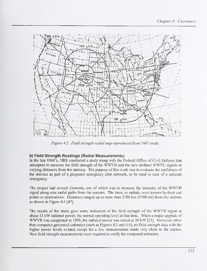
Chapter 4 - Customers
Figure 4.5. Field strength radial map reproducedfrom 1967 study.
b) Field Strength Readings (Radial Measurements)In the late 1960's, NBS conducted a study along with the Federal Office of Civil Defense that
attempted to measure the field strength of the WWVB and the now-defunct WWVL signals at
varying distances from the stations. The purpose of this work was to evaluate the usefulness of
the stations as part of a proposed emergency alert network, to be used in case of a national
emergency.
The project had several elements, one of which was to measure the intensity of the WWVBsignal along nine radial paths from the stations. The lines, or radials, were known by their end
points or destinations. Distances ranged up to more than 2700 km (1700 mi) from the stations
as shown in Figure 4.5 [47].
The results of the study gave some indication of the field strength of the WWVB signal at
about 13 kW radiated power, the normal operating level at that time. When a major upgrade of
WWVB was completed in 1999, the radiated power was raised to 50 kW [33]. However, other
than computer-generated estimates (such as Figures 4.3 and 4.4), no field strength data with the
higher power levels existed except for a few measurements made very close to the station.
New field strength measurements were required to verify the computed estimates.
113

NIST Time and Frequency Radio Stations: WWV, WWVH, and WWVB
It was determined that data should be taken along the same radial paths used during the original
study, so that the new data could be compared to the old. Although the details of the actual
measurement techniques used for the first study were sketchy, the new measurements were to
be made using techniques developed by the U. S. Navy for accurately measuring field strength
of LF and VLF signals [49]. A specially constructed receiving antenna was purchased and
used with a selective level voltmeter to take the measurements. The measurement sites were
carefially chosen to avoid objects or terrain features that would interfere with the signal [44].
Two sets of measurements were taken. The first, in the fall of 2000, involved taking daytime
readings along the east coast from Maine to North Carolina, and then returning to the
transmitter on the radial path that ends at Cape Fear, North Carolina (Table 4.4). The
following year another set of daytime measurements were taken along the Jupiter, Florida
radial path, then along the coast of the Gulf of Mexico, returning along the Brownsville, Texas
radial (Table 4.5).
Table 4. 4. Samplefield strength data, East coast/Cape Fear radial, September-October 2000.
Location Distance (km) Signal strength (^V/m)
Bangor, Maine 2960 43
Laurel, Maryland 2408 240
Elizabethtown, North
Carolina
2418 170
Mammoth Cave, Kentucky 1688 380
Fulton, Missouri 1131 240
Hiawatha, Kansas 828 1202
Trenton, Nebraska 342 4786
Table 4.5. Samplefield strength data, Jupiter-Brownsville radial, January-February 2001.
Location Distance (km) Signal strength (|uV/m)
Miami, Florida 2828 85
Jacksonville, Florida 2632 76
Madison, Florida 2267 120
Hancock County,
Mississippi
1801 569
Beaumont, Texas 1531 1135
Brownsville, Texas 1713 631
The results of these measurements are "snapshots" ofWWVB signal levels on a particular day
in a particular area. While a full-fledged study of WW\^ field strength would involve
continuous readings over a period of months from many locations (a fijture possibility
114

Chapter 4 - Customers
discussed in the next section), these radial measurements seem to vahdate the computer-
generated estimates, and more radial measurements are planned for the future. One interesting
finding of the radial measurements was the daytime field strength of 43 \iWlm recorded in
Bangor, Maine. This suggests that a properly designed receiver could successfully decode the
WWVB signal in the far northeast comer of the United States, even during the daylight hours.
c) Monitoring Field Strength in Near Real TimeAt this writing (2004), NIST is developing a field strength monitoring system that will
continuously collect signal strength readings from WWVB receivers located across the United
States. This information will be sent back to the NIST Boulder laboratories via an Internet
connection and displayed in near real-time on the Time and Frequency Division web site at
http://tfnist.gov. This will help WWVB customers determine whether there are any current
problems with the broadcast. This system was not completely operational at the time of this
publication, but signal strength meters have already been installed at both NIST campuses
(Boulder, Colorado and Gaithersburg, Maryland). Once completed, this system is expected to
provided more valuable data than any previous field strength study.
An informal, internal monitoring program has been in place for several years, using data
collected fi-om receivers located at the NIST laboratories in Boulder, Colorado, at station
WWVH in Hawaii, and until recently, at a United States Naval facility in Annapolis, Maryland.
Data collected from these sites help NIST personnel determine whether the WWVB signal is
being transmitted properly.
C. How the NIST Radio Stations are Used by their CustomersThree surveys of the radio station audience have been conducted by NBS/NIST in an attempt to
find out how the radio stations are used, and to determine the overall level of customer
safisfaction. The first survey, conducted in 1975, received over 12,000 responses and the
results were published as NBS Technical Note 674 [50]. The second survey, conducted in
1987 to 1988, received over 6,000 responses. The survey results were not formally published
by NIST, but a summary of the results appeared in an International Telecommunication Union
(ITU) document [51]. The most recent survey, conducted in 2001, had nearly 15,000
respondents, and the results were made available by NIST via the Internet [52]. The 1975
survey was specific to HF radio and did not include questions about WWVB. The two more
recent surveys were extended to cover all NIST time and frequency services, including
WWVB.
The information in this section was compiled from survey results, and from information
obtained from customer letters, phone calls, and emails.
1. WWV/WWVH CustomersThis section looks at WWV and WWVH customers, and describes some of the ways they use
the service. It categorizes customers based on their primary application: time, frequency, or
use of the non-timing related voice announcements.
115

NIST Time and Frequency Radio Stations: WWV, WWVH, and WWVB
a) Time CustomersNot surprisingly, all three surveys identified the voice time-of-day announcements as the most
widely used feature on WWV, and that nearly all users of the broadcasts use this feature.
Figure 4.6 shows results from the 2001 survey. All three surveys also showed that the most
common application for the voice time-of-day announcements is the manual synchronization of
clocks and watches. Since WWV and WWVH are the only precision wireless time signals
available by radio in the United States, they are acknowledged as the best available source for
manual clock synchronizations. Many wireless time codes exist, but only WWV and WWVHprovide a signal that can be listened to and used with no decoding equipment other than the
human ear. A number of other timing applications have been identified as listed below.
Which types of information on WWV and WWVH do you
yse at least occasionally?
GPS status
GEO Alerts
Marine Weatfier
DUT1 Values
Standard Frequency
1 -Second Ticks
BCD Time C<&de
Voice Time of Day
a 2000 4000 ^00 8000 10000 12000
Figure 4.6. Resultsfrom 2001 survey regarding WWV/WWVH usage.
Time Code - The WWV time code (on a 1 00 Hz subcarrier) serves as a reference signal for
radio-controlled clocks that drive timing displays or provide time information to a computer
system. The nature of the HF signal makes WWV radio-controlled clocks harder to design,
116
Chapter 4 - Customers
more expensive (both the antenna and receiver), and perhaps less reliable than their WWVBcounterparts. However at this writing, at least three U.S. companies (listed alphabetically) still
produce and sell WWV time code receivers: Chrono-Log (Havertown, Pennsylvania), ESE (El
Segundo, California), and U.S. Traffic Corporation (Santa Fe Springs, California). In addition,
many older, discontinued time code receivers manufactured by other companies remain in use.
These products automatically synchronize to the WWV signal without operator intervention.
Since the time code actually consists of audio information, there have been, at various times,
low cost products available that synchronize computer clocks after decoding the time from the
WWV/WWVH station audio. These products have used various schemes to obtain the audio,
such as a cable connected to the headphone jack of a shortwave receiver, or an acoustic coupler
connected to a telephone after dialing the telephone time-of-day service.
One noteworthy example of time code usage was a project begun by the city of Los Angeles,
California in 1988 to use WWV/WWVH receivers to synchronize traffic lights at more than
1,000 intersections. City officials estimated that this project saved motorists 55,000 hours a
day in driving time, 22 million gallons a year in fiael, and 6,000 to 7,000 tons of pollutants per
year [53].
Hobbyists and Educators - WWV and WWVH certainly have value as educational tools, as
evidenced by the many thousands of letters, phone calls, and e-mails received by NIST over the
years from teachers, scout leaders, parents, amateur radio operators, and others. These
educators have related numerous examples of using the signals to teach and mentor young
people about timekeeping, science, radio, and other related topics.
Mariners (navigational use) - Even in today's world where GPS receivers are widely
available, a few sailors still engage in celestial navigation, and many others use it as an
emergency backup to GPS. Celestial navigation requires a small amount of equipment
(sextant, calculator, compass, astronomical tables, etc.), and an accurate time source, which can
be the audio time announcements from WWV or WWVH received with a low cost shortwave
portable [54]. Several comments from the 2001 Customer Survey [52] pertained to celestial
navigation, including this one (edited slightly for clarity):
"My family is interested in sailing. We have crossed the Atlantic three times
between U.S. & U.K. in our 26 ft. boat. We have always used our sextant, your
signal (WWV) and BBC time signalsfor navigation. Many thanks!
"
Local Telephone Time-of-Day Services - ft was estimated in the 1970s that about four billion
telephone calls were made annually to local telephone time-of-day services, and that nearly all
of these services used WWV as their synchronization reference [55]. The number of calls
made to local phone services is undoubtedly much smaller today, since there are many alternate
ways to get the time; and phone companies can synchronize their services to other time
sources, such as WWVB or GPS. However, we are aware that some phone companies in large
metropolitan areas synchronize their time-of-day services to WWV using equipment that has
been in place for many years. While estimating their numbers is difficult, it is clear to us that a
117

NIST Time and Frequency Radio Stations: WWV, WWVH, and WWVB
substantial number of people still indirectly get the time from WWV when they call their local
phone company's time number.
Astronomers - The 2001 Customer Survey [51] contained a number of comments from
customers using WWV/WWVH signals to time astronomical observations, including lunar
occultations and meteor showers. Audio time signals can be heard in the dark when clock
displays can not be seen, or when the light from clock displays cannot be tolerated. Another
technique used by astronomers is to film an astronomical event with a camcorder and play
WWV in the background as a "soundtrack." The time accuracy of this technique is limited by
the frame length of the video, which is typically about 33 ms. This audio track authenticates
the time of the filmed observation, and is invaluable when sightings from different locations
are compared [56].
Time Interval Calibrations - Many private and government calibration laboratories
(particularly state metrology laboratories) use WWV or WWVH as a reference signal for time
interval calibrations, such as the calibration of stop watches and timers. This allows the
laboratory to establish traceability for time interval measurements back to NIST and to the
International System (SI) definition of the second. The audio tones are used as signals to start
and stop the timer being calibrated [57].
b) Frequency CustomersThe performance of WWV and WWVH as a reference source for frequency calibrations is
severely limited by the instability of the HF radio path. While oscillator performance has
improved by many orders of magnitude since WWV first went on the air, the received
frequency uncertainty of HF broadcasts has remained virtually unchanged [58]. Thus, it has
been many years since HF radio broadcasts have been capable of calibrating the best available
oscillators. As early as the 1950's, WWV had been supplanted by U. S. military VLFbroadcasts as the primary frequency reference at many calibration laboratories [59]. From the
1960's to the 1990's, frequency calibration laboratories employed a number of reference
signals with lower uncertainties than HF, including television signals, satellite signals, and LFsignals from WWVB and LORAN-C [60]. And shortly after the Global Positioning System
(GPS) satellites were declared fiilly operational in late 1993, GPS had become by far the most
widely used signal for frequency calibrations of the best available oscillators [61].
Although it has been some 50 years since WWV and WWVH have been the frequency
calibration reference of choice, they still are widely used for frequency calibrations with
modest uncertainty requirements, including:
Radio Transmitter and Receiver Calibrations - When WWV began broadcasting in the
1920's, radio was in its infancy. The burgeoning number of new broadcast stations created a
huge frequency calibration problem. Broadcasters had to stay near their assigned frequencies
so that they did not interfere with adjacent stations. Radio receivers needed tuning dials that
were at least reasonably accurate so that listeners could find the station they were looking for.
By broadcasting as accurate a frequency signal as was then possible, WWV played a very
118
Chapter 4 - Customers
important role in solving this problem. It quickly became a reference for the calibration of both
radio transmitters and receivers [3].
As oscillator technology improved, beginning with the appearance of the first quartz oscillators
in the late 1920's, the radio frequency problem became less serious, and today it is relatively
easy for most broadcasters to stay within tolerance of their assigned frequency allocation (20
Hz for AM radio, 2000 Hz for FM, and 1000 Hz for television video signals) [62]. However,
all transmitted frequencies need to be checked periodically, and the 2001 Customer Survey [52]
indicated that WWV is still widely used for the calibration of both commercial and amateur
transmitters, and especially by radio amateurs and shortwave listeners who use the signals to
calibrate their receiver dials.
Audio Frequency Calibrations Including Standard Musical Pitch (440 Hz tone) -
WWV/WWVH broadcast standard audio frequencies of 440, 500, and 600 Hz for use as a
traceable calibration source. The 440 Hz is particularly noteworthy, since it serves as the
ultimate reference for the calibration of pianos and other musical instruments. Since 1939,
A440 (the musical note A above middle C at 440 Hz) has been the internationally recognized
standard for musical pitch [63]. The piano tuner listens to a standard musical pitch and
compares it to the same note on the piano keyboard. The piano is then adjusted by tightening or
loosening strings, until it agrees with the audio standard. The actual piano tuning is generally
done with a transfer standard such as a tuning fork or an audio tone generator, since those
devices are easy to bring to the piano site and their signals are always available. However, the
audio from WWV/WWVH is often used as a reference for calibrating the transfer standard.
Low Cost Test Equipment - WWVAVWVH are used by some calibration laboratories to
provide traceable frequency calibrations of low cost test equipment, such as signal generators
and frequency counters. The signals serve as an acceptable reference if the uncertainty
requirement for the device under test does not exceed 1 x 10"'. They are also used for a quick
check of test equipment that does not require certification.
Calibration of Police Radar Devices - State metrology labs are often responsible for the
calibration of tuning forks used by law enforcement agencies to check the radar devices that
measure vehicle speed. The calibration of tuning forks is a simple frequency calibration where
uncertainties of 1 x 10"^ are adequate for measuring vehicle speed to within a fraction of a mile
per hour. WWV/WWVH provides a convenient and accepted way to establish traceability for
these measurements using techniques that utilize either the 600 Hz audio tones as a reference
for calibrating tuning forks [64], or that use the 10 MHz carrier as a reference for calibrating a
frequency counter that is then used to calibrate tuning forks [65].
c) Voice Announcement Customers (Non-Timing Announcements)As Figure 4.6 indicates, a number of WWV/WWVH listeners use the non-timing information
contained in the voice announcements. A few types of these customers are described below.
119

NIST Time and Frequency Radio Stations: WWV, WWVH, and WWVB
Radio amateurs and short wave listeners - Since WWV and WWVH are widely used by the
amateur radio community, it is probably no surprise that the geophysical alerts provided by
NOAA are the station's second most popular feature, next to time and standard frequency
information (Figure 4.6). The geophysical alerts provide information about the current
conditions for HF radio propagation. They allow users to estimate how far radio signals will
travel, and the maximum usable frequency and lowest usable frequency for a given time and
location [38]. Although this information is available by telephone and hitemet, it is convenient
for radio operators to get it from their radio without requiring any additional equipment.
Mariners - The National Weather Service (a division of NOAA, and like NIST part of the
United States Department of Commerce) provides voice announcements of marine storm
warnings on both the WWV and WWVH broadcasts. Atlantic high seas warnings can be heard
at 8 and 9 minutes past the hour on WWV; Pacific high seas warnings can be heard at 10
minutes past the hour on WWV, and at 48 to 5 1 minutes past the hour on WWVH. Since the
time announcements are sometimes used for celestial navigation (as previously discussed), the
HF broadcasts have long been recognized as a good medium for marine storm warnings.
GPS Users - Users of the Global Positioning System (GPS) can hear a 45 s long status report
at 14 and 15 minutes after the hour on WWV, and at 43 and 44 minutes after the hour on
WWVH. The reports are provided by the United States Coast Guard. Figure 4.6 indicates that
a substantial number of customers listen to these reports.
2. WWVB CustomersWWVB customers (described in 4.A.2) now number in the millions, due to the large number of
radio controlled clocks and wrist watches that synchronize to the 60 kHz signal. While the
huge number of time-of-day users is what the station is primarily known for, this section will
focus on other types of customers who get time and/or frequency from WWVB.
a) Time CustomersWWVB time distribution receivers are used at many organizations that require time legally
traceable to NIST, and that need more reliable reception than can be provided by
WWV/WWVH. The largest manufacturer of these products has historically been the
Spectracom Corporation of East Rochester, New York, which entered the WW^B marketplace
in 1972. Time distribution receivers continually track the signal, and require an outdoor
antenna for best results. They are used to distribute time to communications systems, computer
networks, wall clocks (synched to a master clock), voice recorders, radio consoles, phone
systems, 9-I-I emergency systems, police dispatch systems, and so on. This type of receiver
includes a large digital clock display, and typically outputs a time code in several different
formats. Time codes in text and binary format are output in computer readable format using
standard serial interfaces such as RS-232 and RS-485. Standard time code formats like those
defined by the Inter-Range Instrumentation Group (IRIG) or the National Emergency NumberAssociation (NENA) are also available. In some systems, a WWVB receiver serves as a
backup or alternative time source to a Global Positioning System (GPS) receiver.
120

Chapter 4 - Customers
Another large group ofWWVB timing customers use the signals to satisfy the requirements of
the Order Audit Trail System (OATS) prescribed by the National Association of Securities
Dealers (NASD) Securities and Exchange Commission. Under NASD Rule 6957, all clocks
used by member firms must be synchronized to within 3 seconds of UTC(NIST). This includes
all computer clocks used to record time associated with electronic order handling or execution
software (a requirement in effect since August 7, 1998). It also includes all mechanical clocks,
including manual devices used to record time (a requirement in effect since July 1, 1999). This
means that NASD members that use mechanical time-stamping devices or record order receipt
time on order tickets manually must do so from a synchronized business clock. Obviously,
both the NIST computer time services [36] and the low-priced WWVB clocks play a huge role
in allowing NASD members to achieve OATS compliance.
Some WWVB receivers produce an on-time 1 pulse per second (pps) signal that can be used
for synchronization purposes. However, synchronization to within better than 1 ms is generally
not attempted with WWVB. The factors that limit the accuracy of WWVB receivers as a
synchronization source are fiilly discussed in the measurement uncertainty sections found in
Chapter 5, but we can briefly describe them here. Receivers that generate a 1 pps signal have
to choose a cycle of the carrier to use as the on-time marker (OTM). The period of the 60 kHzcarrier is 16.67 )is, so the OTM shifts by that amount whenever a new cycle is selected. There
might be a range of 30 or more cycles that could be chosen as the OTM, leading to an
ambiguity of 500 jis or more. This is in addition to the path delay (a function of the receiver's
distance from the station) which would need to be estimated and corrected for.
b) Frequency CustomersPrior to the advent of low priced radio controlled clocks, the largest group of WWVBcustomers were those who used the signals as a frequency reference. Numerous calibration
laboratories and electric power companies relied on the signals as the reference for their
frequency measurements. The path of the 60 kHz signal is very stable, particularly in the
contiguous 48 states, where mostly groundwave signals are received. It is possible to measure
frequency with an uncertainty of a few parts in lO'^ when averaging for one day, and lower
uncertainties are possible over longer intervals. This probably makes WWVB the best
alternative to GPS as a frequency calibration reference, with the possible exception of the 1 00
kHz LORAN-C system, whose long range future has yet to be decided at this writing (2004).
WWVB receivers designed to work as frequency standards can distribute standard frequencies
or be used as a reference to calibrate other oscillators. These devices are known as carrier
phase tracking receivers. They discipline a stable quartz oscillator to agree with the WWVBsignal and outputs standard frequencies such as 100 kHz, 1 MHz, 5 MHz, and 10 MHz. Somereceivers designed as frequency standards ignore the time code entirely and do not output time-
of-day or an on-time pulse. WWVB frequency standards were once easy to find (sold in the
United States by companies such as Spectracom, Hewlett-Packard, Tracor, and others), but
have currently disappeared from the marketplace, although hundreds of existing units still
remain in use. We hope to see new products of this type reappear on the marketplace, both as
an alternative and as a back-up to GPS disciplined oscillators. To help support WWVB
121

NIST Time and Frequency Radio Stations: WWV, WWVH, and WWVB
frequency users, NIST publishes phase monitoring data that is collected by averaging the
signals received in Boulder against the UTC(NIST) time scale for one day. This information
is available on the Time and Frequency division web site (Table 4.6).
D. Customer Interaction and SupportThis section describes how NIST interacts with customers via telephone, e-mail, and postal
mail. It also describes how information about the radio stations is distributed to customers.
1. Distribution of Information about the NIST Radio Stations
This section describes how information about the NIST radio stations is distributed to existing
customers and potential new customers. A good portion of this activity is educational. NISTattempts to make the public aware of the existence of the services, and to educate the public on
how to use the services.
a) Web Site
The NIST web site contains separate sections for all three NIST radio stations, and a large
amount of information about each station. The web is used to distribute information about
broadcast outages, broadcast formats, sources for receivers, and to answer frequently asked
questions. The amount of material presented on the Web about the radio stations was expanded
in the period from 2001 to 2004, and further expansion is planned. Table 4.6 lists some of the
topics covered on the web site, and provides links to each topic.
b) Publications
The primary publication describing the radio stations is NIST Special Publication 432, entitled
NIST Time and Frequency Services, which was last revised in January 2002 [38], the first
revision in about 1 1 years. The SP 432 contains most of the information found on the web site,
and some unique information not found elsewhere. It is intended both as an introduction to the
NIST radio stations, and as a guide to their use.
Guides to the NIST (formerly NBS) Time and Frequency Broadcast Services have historically
been very popular, with many thousands of copies printed. In recent years, even more copies
have been distributed electronically. Since 1976, four guides have been published as Special
Publication 432. From 1960 until 1974, eleven guides were published as NBS Special
Publication (or Misc. Publication) 236. Other publication numbers were used prior to 1960.
These guides are now available from the http://tf.nist.gov web site as historical references.
While the SP 432 provides a general introduction to the NIST radio stations, it does not provide
much information about advanced measurements using the broadcasts. For this information,
NIST offers "The Time and Frequency User's Manual," NIST Special Publication 559,
published in 1976, 1979, and most recently in 1990 [60]. The SP 559 is one of the most
popular downloads from the NIST web site, with thousands of copies downloaded monthly,
and it is expected that a new edition will be written and published. It has chapters dedicated to
both HF and LF radio broadcasts.
122

Chapter 4 - Customers
Table 4. 6. Web links to NIST radio station information.
WWV Home Page http://tfnist.gov/stations/wwv.html
Information broadcast by WWV http://tfnist.gov/stations/iform.html
WWV time code http://tfnist.gov/stations/ww^timecode.htm
WWV broadcast format http://tfnist.gov/stations/wwv-wheel.htm
WWV station library http ://tfni St .gov/stations/h flibrary .htm
WWV broadcast outages http://tfnist.gov/stations/wwvoutages.htm
WWVH Home Page http ://tfn i st .gov/stations/wwvh.htm
Information broadcast by WWVH http://tfnist.gov/stations/iform.html
WWVH time code http://tf.nist.gov/stations/wwvtimecode.htm
WWVH broadcast format http://tfnist.gov/stations/wwvh-wheel.htm
WWVH station library http ://tfni St .gov/stations/h flibrary .htm
WWVH broadcast outages http://tfnist.gov/stations/wwvoutages.htm
WWVB Home Page http://tfnist.gov/stations/wwvb.htm
WWVB coverage area http://tfnist.gov/stations/wwvbcoverage.htm
WWVB time code http://tfnist.gov/stations/wwvbtimecode.htm
WWVB station library http://tfnist.gov/stations/lflibrary.htm
WWVB broadcast outages http://tfnist.gov/stations/wwvboutages.htm
WWVB phase monitoring data http ://tfn i st .gov/service/wwvbtrace .htm
General information about radio-controlled
clocks
http://tfnist.gov/stations/radioclocks.htm
Manufacturers of time and frequency radio
receivers
http://tfnist.gov/general/receiverlist.htm
Telephone Time-of-Day Service http://tfnist.gov/stations/sig.html
Many other publications about the radio stations are available in the ''station libraries" found on
the web site (the links are listed in Table 4.6). It should be noted that many of the publications
about the stations date back to the 1970's or earlier. Very little about the stations was
published in the 1980's and 1990's. This is probably because the stations represent a well-
established, "tried and true" technology, and most of the new documents published by the
division focus on recent experiments, measurements, and discoveries. However, the document
you are reading, the recent revision of the SP-432 [38], and the material recently added to the
NIST web site are tangible examples of an attempt to reverse this trend.
123

NIST Time and Frequency Radio Stations: WWV, WWVH, and WWVB
c) Technical Support (E-mail, Phone, and Postal Mail)
NIST personnel quickly respond to queries made by customers about the radio stations, and
offer technical support whenever necessary, as described below.
E-mail - NIST typically receives (on average) about 20 e-mails per week about the radio
stations, with the majority dealing with radio-controlled clocks. Some e-mails go directly to
the radio stations, others go to the Time and Frequency Services group in Boulder, Colorado.
E-mail addresses are listed on the division web site at http://tfnist.gov. Most e-mails are
answered within 24 to 48 hours, unless research is required to answer the question. In some
cases, when the initial e-mail is ambiguous or incomplete, and an e-mail conversation is
necessary, but most issues are resolved with one or two e-mails.
Phone calls - While e-mails are preferred, NIST staff is available during normal business
hours on Monday through Friday to field telephone calls about the radio stations. It is
estimated that at least 10 calls per week are received, and most questions are immediately
answered.
Postal mail - The stations receive several letters per week via regular postal mail. Somequalify as "fan mail" from enthusiastic customers. Others ask questions, or make the QSLrequests discussed earlier. Letters/QSLs are usually responded to within two or three business
days after their receipt.
d) HF Station Voice AnnouncementsNIST sometimes inserts announcements into the WWV and/or WWVH broadcasts that inform
customers about news related to the broadcast services. Past experience has shown that these
voice announcements are an effective way to reach our customer base, particularly those whohaven't visited (or seldom visit) the division web site. For example, the 2001 Customer Survey
[52] was publicized using broadcast voice announcements, and this resulted in several thousand
respondents either requesting printed survey forms or responding through the web site.
124

Chapter 5 - Measurement Uncertainties
Chapter 5
Measurement Uncertainties
This section discusses the measurement uncertainties of the signals transmitted by the NISTradio stations, and of the signals received by customers. It also discusses establishing
traceability to UTC(NIST).
A. Frequency Uncertainty of Transmitted Radio SignalsThis section discusses the frequency uncertainty of the signals broadcast by NIST radio
stations as they leave the transmitter sites. It also describes the allowable tolerances for each
broadcast with respect to the UTC(NIST) standard maintained in Boulder, Colorado and howthe quality control system at NIST maintains these tolerances.
The frequency uncertainty of the stations is essentially determined by how well station
personnel steer the frequency of the station clock to agree with UTC(NIST). The delays
through the station hardware, including the transmitters and antenna systems are expected to
remain relatively constant, and therefore they only impact the time uncertainty, and not the
frequency uncertainty. The average frequency of the station clocks is expected to deviate
from UTC(NIST) by only about 1x10"'^ when averaged over the course of a day or longer.
1. Transmitted Frequency Uncertainty of WWV and WWVBSince WWV and WWVB share the same site, they share the same station clock, a commercial
cesium standard. Two backup cesium standards are always on-line, and one will automatically
replace the on-line standard in the event of a failure, as described in Chapter 2. WWV is
located in the same building as the station clock, and both 5 MHz and I Hz signals are
distributed from the station clock to the transmitters (Figure 2.2). WWVB is in a separate
building, and is connected to the station clock by an underground transmission line that is
approximately 436 m in length, and that has a transmission delay of approximately 1.9 |as.
The station clock provides the reference for all time and frequency functions performed by the
station. On WWV, all five carrier frequencies (2.5, 5, 10, 15, and 20 MHz) are derived from
this clock, as are the 100 Hz subcarrier, the 1 Hz on-time marker (OTM), and the audio
frequencies (440 Hz, 500 Hz, 600 Hz, 1000 Hz, and 1500 Hz). On WWVB, the 60 kHz carrier
and the I Hz OTM are derived from this clock. Therefore, the frequency uncertainty of the
signals transmitted by both stations is directly tied to the performance of the station clock, and
to how well the clock can be steered to agree with the national frequency standard located
approximately 80 km away in Boulder.
125

NIST Time and Frequency Radio Stations: WWV, WWVH, and WWVB
a) The Method Used to Control the Station Clock FrequencySince the transmitters operated by NIST have always been located "off-site", far away from the
laboratory where the national standards are maintained, controlling the station clock at each
transmitter site to closely agree with UTC(NIST) has always presented a unique challenge.
Many methods were used in the early days to steer the station clock, including carrying
working standard wavemeters to the station [4, 5], carrying portable oscillators to the station,
the monitoring of VLF and LF signals at the station site [28], transmitting a 50 MHz timing
signal from the Boulder laboratories to the station [66], or the common-view reception of
television signals [67].
While all of the above methods met the uncertainty requirements of their respective eras, the
situation became much easier with the launch of the GPS satellite constellation (which began in
1978), and the introduction of the common-view GPS measurement technique [68]. Common-view GPS has been used to continuously compare the WWV/WWVB station clock to UTC(NIST) since the 1980's. Two common-view GPS receivers are located at the Fort Collins site.
One of the receivers is an original NBS single-channel receiver designed by NIST (then NBS)personnel in the 1980's [69]. The other is a commercial single-channel model that performs a
nearly identical fimction. Both receivers follow the common-view tracking schedule published
by the Bureau International des Poids et Mesures (BIPM), recording 13 minute tracks from
each satellite listed on the schedule [61]. They compare the on-time I Hz signal from the
station clock to UTC(NIST), using signals from the GPS satellites as a common-view
reference. Both receivers are connected by analog modems to dedicated telephone lines, and
the data can be downloaded at any time for analysis.
Common-view measurements have a long history in time and frequency metrology, since they
provide a usefiil way to compare clocks at different locations. The premise is simple: two
laboratories can measure the time difference between their clocks by each comparing their
local clock to the same reference at the same time. The laboratories record and exchange their
measurements, and the difference between the measurements is the difference between the
times kept by the two clocks. The common-view reference drops out of the equation.
To visualize how the common-view technique works, imagine two people living at opposite
ends of town who want to compare the time on the grandfather clocks in their living rooms.
This would be an easy problem to solve if they could get the clocks together in the same place
and compare them side by side. However, moving the clocks is not possible. Therefore, each
person agrees to write down the time displayed by their clock when the fire whistle (located
midway between them) blows in their town, an event that happens each day around noon.
They then call or e-mail each other and exchange the time readings. If the first clock read
12:01:35 and the second clock read 12:01:47, then simple subtraction tells them that the second
clock was 12 seconds ahead of the first clock when the fire whistle blew. Whether the fire
whistle blew exactly at noon or not is unimportant. It only matters that it was heard at the same
time at both locations. If so, the measurement reveals the difference between the two clocks,
and the comparison is successfiil.
126

Chapter 5 - Measurement Uncertainties
Instead of a fire whistle, common-view GPScomparisons (Figure 5.1) employ a satellite (S)
and two receivers (A and B). The satellite
transmits a time signal that is simultaneously
received by both receivers. Both receivers
compare the received signal to their local clock
and record the data. Receiver A receives the
signal over the path dsA and compares the
reference to its local clock (S - Clock A).
Receiver B receives the signal over the path dse
and records (S - Clock B). The two receivers
then exchange and difference the data. Delays
that are common to both paths dg^ and dgg
cancel out, but delays that aren't common to bothtroposphere
paths contribute uncertainty to the measurement.'
The result of the measurement is (Clock A -
Clock B) with an error term of (dsA - dse)- This
error term can be estimated and applied as a
correction to the measurement.
ionosphere
Clock A
data exchange
Clock B
On average, nearly 40 common-view tracks are
recorded between Boulder and Fort Collins each
day, and the data are exchanged via telephone
lines. There are several reference GPS receivers
located at the NIST laboratories in Boulder that
are used to compare individual GPS satellite
broadcasts to UTC(NIST). These receivers have been carefully calibrated and their delays are
known to within a few nanoseconds or less. Like the receivers at Fort Collins, they are
connected via analog modems to dedicated telephone lines.
Figure 5.1. Common-view GPS technique.
A dedicated computer system, called the Radio Station Time Monitor (RSTM), dials the GPSreceivers once per day, and downloads data from one or more of the reference receivers in
Boulder, and from the two receivers in Fort Collins, and then automatically stores, graphs, and
displays the data. An RSTM is also installed at WWVH in Kauai and in Boulder. The RSTMcan be configured to dial as many receivers as desired, making it possible for WWV/WWVBnot only to compare their clock to UTC(NIST) in Boulder, but also to compare their clock to
WWVH simply by making a telephone call to Kauai. Station personnel are trained to
download and process the common-view data without using the RSTM, if necessary.
Figure 5.2 shows the RSTM software with a graph displayed containing 325 days of data from
2002 and 2003. The graph shows three traces, one a comparison between UTC(NIST) and
WWV/WWVB, one a comparison between UTC(NIST) and WWVH, and one a comparison
between WWV/WWVB and WWVH.
127

NIST Time and Frequency Radio Stations: WWV, WWVH, and WWVB
1,7, November: 2002)
Daily Averaged Common-vrew Difference
tvtJD.days
M.JD 52709 2003-03-11 2351.27 (Scheduled CV Diff. Time 125000)
Figure 5.2. A graph displayed using the Radio Station Time Monitor (RSTM) software.
Station personnel use the results of the common-view measurements to apply time and/or
frequency corrections to the station clock used as the reference for the broadcasts, enabling
them to control the transmitted frequency to less than 1 x 10''^ with respect to UTC(NIST)when averaged over multiple days. Figure 5.3 shows the daily frequency offset values of the
WWV/WWVB station clock with respect to UTC(NIST) over the 1 year period from May 10,
2003 to May 16, 2004. Some daily values (about 30 days) were lost since the GPS receivers
can store only a few days of data in memory, and data are lost if a phone call is not successfrilly
completed within several days, or if the receiver memory is reset. The average daily frequency
offset seldom exceeds 2 x 10"'^ and that the average frequency offset is near 1 x 10'^ The
largest daily frequency offsets occur on days when station personnel are adjusting the station
clock. Figure 5.4 shows the frequency stability as estimated with the Allan deviation, <3y{x), is
about 8 x 10""* at 1 d, and near 2 x 10"''' after about 2 weeks.
It is important to note that common-view GPS is simply a measurement technique, and that
GPS time is not the reference for any of the NIST stations. GPS satellites are simply used as
the link between the clocks maintained in Boulder, Fort Collins, and Kauai. By design, NISTradio station time is completely independent of the time broadcast by the GPS satellites; a shift
128

Chapter 5 - Measurement Uncertainties
-4.50
WWV/WWVB Station ClockDN10_WWVB.005
80 120 160 200 240 280 320 360
Days (May 2003 to May 2004)
Figure 5. 3. Dailyfrequency offset estimatesfor WWV/WWVB station clock.
or error in GPS time would not change the time broadcast by the radio stations, and the NISTstations would continue to keep and broadcast time without interruption even if GPS were
unavailable. However, in the unlikely event that GPS were unable for an extended period,
another measurement technique would be required to link the station clock to the national
standard. Two candidates would be two-way satellite time transfer [70] since a satellite earth
station exists at the Fort Collins site, or carries of a portable clock from the Boulder
laboratories.
The station clock and all of the backup cesium standards at WWVAVWVB are also monitored
using the NIST Frequency Measurement Service [37], the same service that NIST makes
available to calibration and testing laboratories on a subscription basis. This service allows up
to five oscillators to be simultaneously measured with an uncertainty of 2 x 10"'^ over a 1 day
interval, and allows station personnel to note the performance of all of their cesium standards at
all times.
129

NIST Time and Frequency Radio Stations: WWV, WWVH, and WWVB
Frequency Stabilityl^WV/WWVB station Clock
Averaging Time, x. Seconds
Figure 5. 4. Estimatedfrequency stability ofWWV/WWVB station clock.
2. Transmitted Frequency Uncertainty of WWVHWWVH also uses a commercial cesium standard as its station clock. At least one backup
cesium standard (usually two) is always on-line, and will automatically replace the on-line
standard in the event of a failure, as described in Chapter 2.
The station clock provides the reference for all time and frequency functions performed by the
station. All four carrier frequencies (2.5, 5, 10, and 15 MHz) are derived from this clock, as are
the 100 Hz subcarrier, the 1 Hz on-time marker (OTM), and the audio frequencies (440 Hz,
500 Hz, 600 Hz, 1200 Hz, and 1500 Hz). Therefore, the frequency uncertainty of the signals
transmitted by WWVH is directly tied to the performance of the station clock, and to how well
the clock can be steered to agree with the national frequency standard located about 5495 kmaway in Boulder.
The WWVH station clock is compared to UTC(NIST) using the same common-view GPStechnique previously described in Section 5.A.l.a). Even though the baseline between Kauai
and Boulder is about 70 times longer than the baseline between Fort Collins and Boulder, on
average there are still about 22 common-view satellite observations (each 13 minutes in
duration) recorded each day between Boulder and Kauai. Figure 5.5 shows the daily frequency
offset values of the WWVH station clock with respect to UTC(NIST) over the 1 year period
130

Chapter 5 - Measurement Uncertainties
from May 10, 2003 to May 16, 2004. Some daily values (about 60 days) were lost since the
GPS receivers can store only a few days of data in memory, and data are lost if a phone call is
not successfully completed within several days, or if the receiver memory is reset. The
average daily frequency offset seldom exceeds 4 x 10''^ and that the average frequency offset is
near 2 x 10"'^ The largest daily frequency offsets occur on days when station personnel are
adjusting the station clock.
WWVH Station ClockDN10_WWVH1.005
80 160 240 320
Days (May 2003 to May 2004)
Figure 5.5. Dailyfrequency offset estimatesfor WWVH station clock.
Figure 5.6 shows that the frequency stability as estimated with the Allan deviation, Oy(T), is
near 1 x 10"'^ at 1 d, and near 3 x lO''"* after about 1 month. These uncertainties are larger than
those shown for the WWV/WWVB station clock (Figures 5.3 and 5.4). This can be attributed
to at least two factors: the cesium standard used at WWVH during this period is older and less
stable than the device used at WWV/WWVB and requires more frequent adjustments, and
larger temperature fluctuations occur at the Kauai site than at the Fort Collins site due to a
poorer quality ventilation and air conditioning system. It is important to note, however, that the
Fort Collins site supports both an HF and an LF broadcast, whereas only HF is broadcast from
Kauai. Since the received frequency uncertainty of an LF broadcast is potentially several
orders of magnitude smaller than the receiver frequency uncertainty of an HF broadcast, the
frequency control requirements for the station clock are necessarily more stringent in Fort
Collins then they are in Kauai.
151

NIST Time and Frequency Radio Stations: WWV, WWVH, and WWVB
Frequency Stability^A/WVH station Clock
Averaging Time, x. Seconds
Figure 5. 6. Estimatedfrequency stability ofWWVH station clock.
To assure quality control of the broadcasts, the WWVH staff also calculates their daily offset
(via GPS common-view) relative to the United States Naval Observatory (USNO) in
Washington, DC, and to the Communication Research Laboratory (CRL) in Tokyo, Japan.
Daily comparisons of the station clock are also made against signals received from the
WWVB transmitter. The results of all of these measurements are entered into the station
logbooks.
The station clock and all of the backup cesium standards at WWVH are also monitored with
the NIST Frequency Measurement Service [37], the same service that NIST makes available to
calibration and testing laboratories on a subscription basis. This service allows up to five
oscillators to be simultaneously calibrated with a measurement uncertainty of 2 x 10"'^ over a 1
day interval, and allows station personnel to note the performance of all of their cesium
standards at all times.
B. Time Uncertainty of Transmitted Radio SignalsEach station transmits an on-time marker (OTM) that is synchronized as closely as possible
with UTC(NIST). The station clocks produce a 1 pulse per second (pps) timing signal that is
synchronized to UTC(NIST) to within ±1 ^s. This allowable tolerance is easily met, and
normally the OTM is synchronized at its source to within a few hundred nanoseconds or less.
132
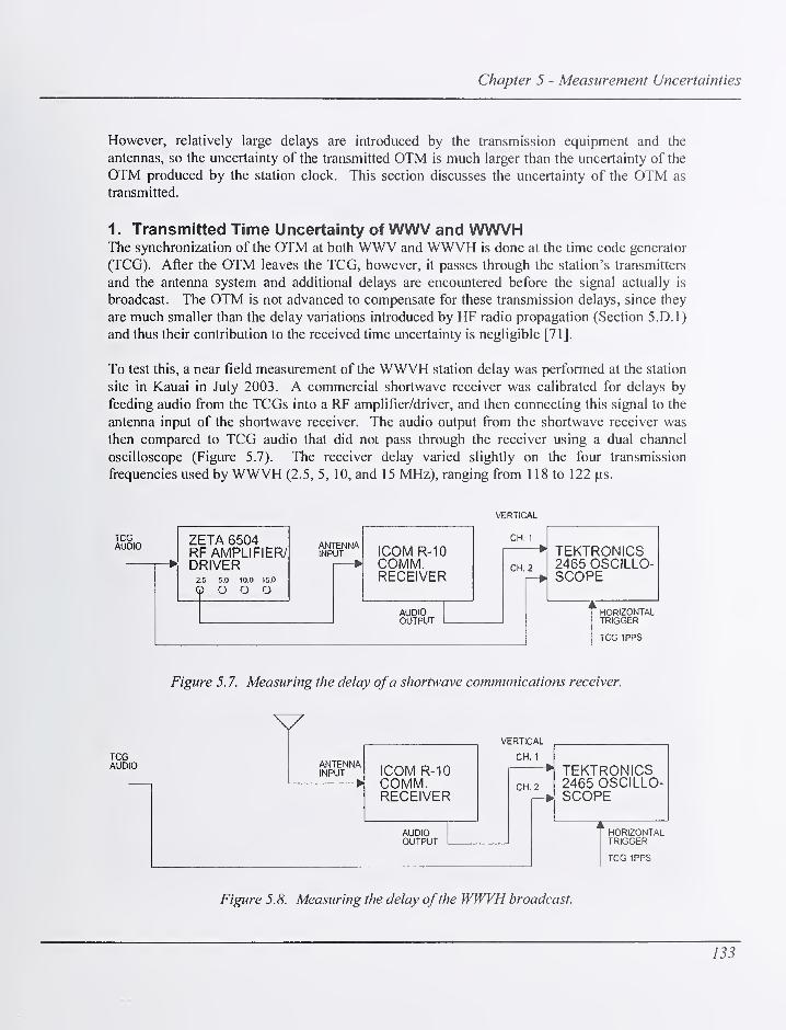
Chapter 5 - Measurement Uncertainties
However, relatively large delays are introduced by the transmission equipment and the
antennas, so the uncertainty of the transmitted OTM is much larger than the uncertainty of the
OTM produced by the station clock. This section discusses the uncertainty of the OTM as
transmitted.
1 . Transmitted Time Uncertainty of WWV and WWVHThe synchronization of the OTM at both WWV and WWVH is done at the time code generator
(TCG). After the OTM leaves the TCG, however, it passes through the station's transmitters
and the antenna system and additional delays are encountered before the signal actually is
broadcast. The OTM is not advanced to compensate for these transmission delays, since they
are much smaller than the delay variations introduced by HF radio propagation (Section 5.D.1)
and thus their contribution to the received time uncertainty is negligible [71].
To test this, a near field measurement of the WWVH station delay was performed at the station
site in Kauai in July 2003. A commercial shortwave receiver was calibrated for delays by
feeding audio from the TCGs into a RP amplifier/driver, and then connecting this signal to the
antenna input of the shortwave receiver. The audio output from the shortwave receiver was
then compared to TCG audio that did not pass through the receiver using a dual channel
oscilloscope (Figure 5.7). The receiver delay varied slightly on the four transmission
frequencies used by WWVH (2.5, 5, 10, and 15 MHz), ranging from 1 18 to 122
TCGAUDIO ZETA 6504
RF AMPLIFIER/DRIVER
2.5 5.0 10.0 15.0
Q O O O
ANTENNAINPUT ICOM R-10
COMM.RECEIVER
AUDIOOUTPUT
VERTICAL
CH. 1
CH. 2
*1 TEKTRONICS2465 OSCILLO-SCOPE
HORIZONTALTRIGGER
TCG 1PPS
Figure 5. 7. Measuring the delay ofa shortwave communications receiver.
TCGAUDIO ANTENNA
INPUT—-—
H
ICOM R-10COMM.RECEIVER
VERTICAL
CH. 1
AUDIOOUTPUT
CH. 2
TEKTRONICS2465 OSCILLO-SCOPE
HORIZONTALTRIGGER
TCG 1PPS
Figure 5.8. Measuring the delay ofthe WWVH broadcast.
133

NIST Time and Frequency Radio Stations: WWV, WWVH, and WWVB
The calibrated receiver was then used to receive the WWVH signal off the air at each of the
four frequencies. The distance between the receiving antenna and the transmitting antennas
ranged from 107 to 214 m, and the free space delay was calculated for each measurement.
Then, the audio output from the broadcast was compared to the TCG audio that did not pass
through the station's transmission system using a dual channel oscilloscope (Figure 5.8). The
results of the test are shown in Table 5.1 and show that the station delay ranged from 3.3 to
59.6 |is, depending upon the transmission frequency. Similar delays exist at WWV.
Table 5. 1. Results ofWWVH broadcast delay measurements.
Frequency Receiver- Measured
(MHz) transmitter reception
distance (m) delay (|is)
Receiver
delay
(MS)
Free space WWVHtransmission broadcast
delay (|is) delay (|j,s)
2.5 214 126 122 0.71 3.3
5 183 178 118 0.61 59.4
10 142 150 119 0.47 30.5
15 107 178 118 0.36 59.6
2. Transmitted Time Uncertainty of WWVBThe delay through the WWVB transmission system was measured by consultants from the U.S.
Navy's LF/VLF support group in September-October 2000 [42] and in a follow up study
performed in June-July 2003 [43]. The original goal of this study was to measure the group
delay from the WWVB TCG through the dual antenna system, which was found to be about
500 ^is [42]. However, it was found that the antenna group delay does not apply to the WWVBOTM because the bandwidth of the OTM is much wider than the bandwidth of the antenna
system. The group delay of the antenna does vary widely over the bandwidth of the OTM and
distorts the waveform, but it is not added to the OTM delay.
Table 5.2. WWVB component delays contributing to OTM delays.
Component Delay (|is)
Time code generator 0.00
Microprocessor switch 1.02
Cable to control console 0.17
Control console 0.91
Console to switch through transmitter 11.12
Transmission line / antenna network 3.89
Cumulative delay {\xs) 17.11
134

Chapter 5 - Measurement Uncertainties
The transmitted time delay ofWWVB was estimated by measuring the delay of all components
between the TCG and the antenna terminals, including a microprocessor controlled switch, a
cable that runs from the switch to the control console, the control console itself, the
transmitters, and the transmission line and antenna (Figure 1.19). There are multiple paths
through the transmission system since different TCGs, transmitters, and antennas can be
selected, and several different combinations of components were measured [43]. It was
determined that the typical delay from the TCGs to the antenna system is about 17.1 ^s, as
shown in Table 5.2. Recommendations were given providing ways to reduce or compensate
for this delay and they are being considered at this writing (2004).
The delay through the system is relatively insignificant because it is difficult for receivers to
consistently identify the OTM and use the signal as a precision timing reference (Section
5.D.2). The WWVB OTM is produced by an instantaneous 10 dB power drop of the 60 kHzcarrier that is synchronized with the UTC second as shown on an oscilloscope in Figure 5.9.
The oscilloscope is triggered with the UTC second, and shows the 60 kHz waveform output by
the TCG. However, since the bandwidth of the antenna is much narrower than the OTM step
flinction, the instantaneous 10 dB down step is distorted into a long tailed transient with an
Figure 5.9. WWVB OTM.
135
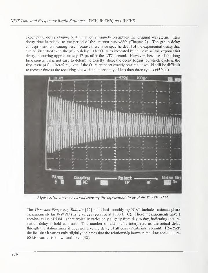
NIST Time and Frequency Radio Stations: WWV, WWVH, and WWVB
exponential decay (Figure 5.10) that only vaguely resembles the original waveform. This
decay time is related to the period of the antenna bandwidth (Chapter 2). The group delay
concept loses its meaning here, because there is no specific detail of the exponential decay that
can be identified with the group delay. The OTM is indicated by the start of the exponential
decay, occurring approximately 17 |as after the UTC second. However, because of the long
time constant it is not easy to determine exactly where the decay begins, or which cycle is the
first cycle [43]. Therefore, even if the OTM were set exactly on-time, it would still be difficult
to recover time at the receiving site with an uncertainty of less than three cycles (±50
Figure 5.10. Antenna current showing the exponential decay ofthe WWVB OTM.
The Time and Frequency Bulletin [72] published monthly by NIST includes antenna phase
measurements for WWVB (daily values recorded at 1300 UTC). These measurements have a
nominal value of 5.64 \is that typically varies only slightly fi"om day to day, indicating that the
station delay is held constant. This number should not be interpreted as the actual delay
through the station since it does not take the delay of all components into account. However,
the fact that it varies only slightly indicates that the relationship between the time code and the
60 kHz carrier is known and fixed [42].
136

Chapter 5 - Measurement Uncertainties
C. Frequency Uncertainty of Received Radio SignalsNIST does not certify or maintain tolerances on the received frequency uncertainty of its radio
stations. The actual uncertainty can vary considerable depending upon the measurement
technique, the type of receiver and antenna used, and environmental conditions. With this in
mind, the following sections provide examples of the measurement uncertainties that can be
typically expected.
1. Received Frequency Uncertainty of WWV and WWVHThe frequency uncertainty of WWV and WWVH signals as received is limited by the
propagation effects of HF radio, which is a much noisier medium than LF radio or signals
broadcast by satellite. ]n theory, much of this propagation noise could be removed or reduced
by averaging. However, in practice, this usually isn't possible. Another limitation ofHF radio
signals is that it is usually not possible for a receiver to stay locked to the same broadcast for a
duration long enough to average down the noise. Therefore, most frequency measurements
made with WWV and WWVH are "instantaneous" measurements, or spot checks of the
frequency of inexpensive quartz oscillators.
WWW/WWVH frequency calibration techniques have been extensively documented in other
NIST publications [73, 74, 38]. Audio frequency calibrations typically have uncertainties of
parts in lO'', but the oscilloscope pattern drift method has been shown to be capable of
measuring the audio frequency tones (such as 500 Hz) with an uncertainty of 1 x 10'^ [73].
Most calibrations of standard frequency oscillators, such as the time base oscillators found in
radio receivers or test equipment, are made using a variation of the "beat frequency" technique,
where the output frequency of an oscillator (the device under test or DUT) is mixed with the
frequency of the RF carrier. This generates a beat frequency that represents the difference
between the two frequencies, or the DUT frequency offset. In some cases, the DUT is adjusted
until the beat frequency is no longer detectable, the condition known as "zero beat." The
simplest form of these measurements produces an audio beat note that is usually listened to
with headphones or "viewed" on the signal strength meter of a receiver [75]. If the 10 MHzcarrier is used, and we assume that the operator can hear an audio beat note down to about 20
Hz, this limits the frequency uncertainty to about 2 x 10"^. Ways of electronically detecting
the beat note obviously work better and have been described by customers [76, 77], but
generally it is difficult to detect anything smaller than 0.1 Hz (1 x 10"* at 10 MHz). For this
reason, 1 Hz (1 x 10"^) is often thought of as the practical limit for an instantaneous
measurement.
There are no dedicated WWVAVWVH receivers marketed as frequency standards, but some
commercially available models do have the ability to produce a 1 pps timing signal. This
signal is derived from the receiver's local quartz oscillator, and coarsely synchronized using the
broadcast information. A measurement was performed at NIST in Boulder using one such
receiver, and using a time interval counter to compare the 1 pps signal to UTC(NIST). Five
minute averages were recorded for a period of six days (Figure 5.11). The receiver used for the
test scans all of the available transmission frequencies and locks to the frequency with the best
reception. The receiver provides no indication when it changes frequencies, and it is not
137
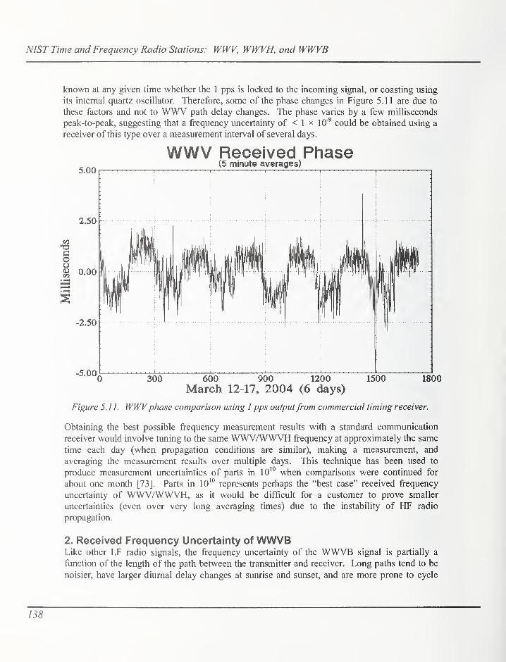
NIST Time and Frequency Radio Stations: WWV, WWVH, and WWVB
known at any given time whether the 1 pps is locked to the incoming signal, or coasting using
its internal quartz oscillator. Therefore, some of the phase changes in Figure 5.11 are due to
these factors and not to WWV path delay changes. The phase varies by a few milliseconds
peak-to-peak, suggesting that a frequency uncertainty of < 1 x 10'^ could be obtained using a
receiver of this type over a measurement interval of several days.
WWV Received Phase(5 minute averages)
5.00 1 ! I I. . .
,
°. ,
I,
2.50 -
^*°^0300 600 900 1200 1500 1800
March 12-17, 2004 (6 days)
Figure 5.11. WWVphase comparison using 1 pps outputfrom commercial timing receiver.
Obtaining the best possible frequency measurement results with a standard communication
receiver would involve tuning to the same WWV/WWVH frequency at approximately the same
time each day (when propagation conditions are similar), making a measurement, and
averaging the measurement results over multiple days. This technique has been used to
produce measurement uncertainties of parts in lO'" when comparisons were continued for
about one month [73]. Parts in lO"^ represents perhaps the "best case" received frequency
uncertainty of WWV/WWVH, as it would be difficult for a customer to prove smaller
uncertainties (even over very long averaging times) due to the instability of HF radio
propagation.
2. Received Frequency Uncertainty of WWVBLike other LF radio signals, the frequency uncertainty of the WWVB signal is partially a
ftinction of the length of the path between the transmitter and receiver. Long paths tend to be
noisier, have larger diurnal delay changes at sunrise and sunset, and are more prone to cycle
1'58

Chapter 5 - Measurement Uncertainties
slips. The quality of the receiving antenna and receiver also impacts the received frequency
uncertainty. A receiver selective enough to filter out interference from other LF sources, and
sensitive enough to stay locked to the same cycle of the carrier will obviously produce the best
results.
The WWVB carrier is continuously tracked at the NIST Boulder, Colorado laboratories using
several carrier phase tracking receivers, and the output of these receivers are compared to UTC(NIST). Cycle slips are rare over this short path (about 80 km), and the diurnal phase shift that
C0
ooCOO(-1
0.6
0.0
-0.6
-1.2
-1.8
-2.4
WWVB Received Phase{compared to UTC(NIST) in Boulder)
1 ''
1'
''
1'
'
iiMiklkllLi
\
•i
1
1'1 1
i
I
\
i
I
4000 8000 12000
Seconds16000 20000
Figure 5. 12. WWVB receivedphase compared to UTC(NIST) for 20000 s.
occurs at sunrise and sunset is typically less than 1 |is. A larger problem than the diurnal when
using WWVB for short term frequency measurements is the phase signature of the station,
which is signaled by advancing the carrier phase 45° for 5 minutes each hour This results in a
phase shift of approximately 2.1 |is occurring at 10 minutes after each hour, and lasting until 15
minutes after the hour [38]. Figure 5.12 shows WWVB phase as recorded for 20000 s (5 h, 33
min, 20 s) during the daylight hours in Boulder. Note that the phase signature is clearly visible
every hour. If frequency calibrations are made using a WWVB receiver and a chart recorder,
these phase shifts can be useful, since they serve as hour markers on the strip chart. However,
if a I pps output from a WWVB receiver is used as a frequency calibration reference on a time
interval measurement system, it is important to average over periods long enough to average
out the effects of the phase signature. This is illustrated in the Allan deviation plot shown in
139

NIST Time and Frequency Radio Stations: WWV, WWVH, and WWVB
Figure 5.13, using the same set plotted in Figure 5.12. Note the sharp drop in the graph at an
averaging time of exactly 1 h. This illustrates that the frequency stability improves
dramatically if data are averaged for 1 h (or more even multiples of an hour) since that
guarantees that the entire 5 minute long phase shift is included in the data and therefore is
averaged out.
O oa>
C!
>
o
Frequency StabilityWWVB Received Phase
: ;. jSiqma For All Tau
i M i M i i
10^ 10^ 10^
Averaging Time, x. Seconds
Figure 5. 13. Estimated short-termfrequency stability ofWWVB carrierphase receiver.
Figure 5.14 shows WWVB received phase recorded over an entire month (each data point is a
1 h average). A close look at the phase data reveals the diurnal variations at sunrise and sunset,
which typically have an amplitude of 500 ns or less over the 80 km path between Boulder and
Fort Collins, an amplitude that can be expected to increase over a longer path. The peak-to-
peak variation for the entire month is about 1 .2 )is. The frequency stability as estimated by the
Allan deviation, ay(T), reaches 2.6 x 10"'^ at an averaging time of 1 d as shown in Figure 5.15.
This indicates that the frequency instability of the WWVB disciplined oscillator used for this
measurement is approximately 30 times larger than that of a high quality GPS disciplined
oscillator [61], but the uncertainties are still sufficiently low to calibrate all time base
oscillators found in test and measurement equipment. Therefore, a WWVB disciplined
oscillator can serve as a backup or alternative to a GPS disciplined oscillator as a frequency
standard for calibration laboratories.
140
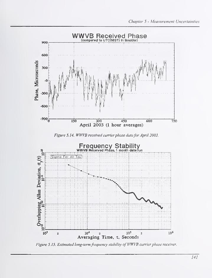
Chapter 5 - Measurement Uncertainties
900
WWVB Received Phase(compared to UTC(NIST) In Boulder)
150 300 450 600April 2003 (1 hour averages)
750
Figure 5. 14. WWVB received carrier phase datafor April 2003.
Frequency StabilityWWVB Received Phase, 1 month data run
10 10* 2 10= 2
Averaging Time, x. Seconds
Figure 5. 15. Estimated long-termfrequency stability ofWWVB carrierphase receiver.
141

NIST Time and Frequency Radio Stations: WWV, WWVH, and WWVB
D. Time Uncertainty of Received Radio SignalsThe NIST radio stations are used primarily for time-of-day information, since most
applications requiring precise time synchronization now rely on GPS, which can provide time
synchronization uncertainties much smaller than 1 |is, whereas the practical limit for the NISTstations is typically about 1 ms. This section takes a brief look at the time synchronization
uncertainty of the received NIST radio signals, and the factors that limit the uncertainty. It also
discusses their measurement uncertainties when used as a time interval reference.
1 . Received Time Uncertainty of WWV and WWVHIn the 1950's, prior to the availability of LF and satellite timing signals, WWV and WWVHwere routinely used for time synchronization experiments and remote clock comparisons, and
uncertainties as small as 0.1 ms were reported under "ideal" conditions [78]. These
measurements required considerable effort, including detailed studies of HF propagation,
particularly knowing how many times the signal was refracted off the ionosphere as it traveled
the path between the transmitter and receiver. Several methods of using the signals for time
synchronization with uncertainties of < 1 ms have been described in detail in previous NBS/NIST publications [73, 74]. These methods require the audio output of a shortwave receiver,
an oscilloscope, knowledge of the propagation delay, and in some cases, other pieces of
standard test equipment. The OTM is synchronized with the start of the 5 ms duration tone
(1000 Hz on WWV, 1200 Hz on WWVH) that occurs every second. This tone, known as the
seconds tick, is preceded by 10 ms of silence and followed by 25 ms of silence. The silence
before and after the pulses makes it easier to identify the seconds tick (Figure 2.6).
Once better time transfer signals became available and atomic clocks were introduced, little
attention was paid to HF signals as a precision time synchronization source. The fundamental
limitations of HF signals made them unsuited for synchronizing the best clocks [58], and better
results could be obtained with less effort using other techniques. Today, most customers whouse WWV or WWVH for time synchronization have modest requirements, and make no
attempt to calibrate the signal path. Since the signals travel at the speed of light, the time is late
by roughly 3.3 ms per 1000 km of signal path. For customers within the continental United
States or near Hawaii, this means that the time uncertainty should be < 15 ms. If a customer
chooses to calibrate the path delay, they can use software that computes the distance between
the transmitter and their receiver. Even then, the practical limit for this path delay estimate is
about 1 ms, and customers would need to be aware of changing HF propagation conditions to
consistently obtain 1 ms uncertainty over all but the shortest paths. Therefore, customers whodepend upon 1 ms time synchronization would probably choose another signal source.
WWV and WWVH are still commonly used as references for time interval measurements,
particularly by state and industrial metrology laboratories that calibrate stopwatches and timers,
since they supply the only precision audio time signals available in the United States. The
audio tones from the stations are used as the signal to manually start and stop the device under
test, and the uncertainty contributed by WWV/WWVH is insignificant when compared to
human reaction time [57].
142

Chapter 5 - Measurement Uncertainties
2. Received Time Uncertainty of WWVBSince WWVB signals are primarily groundwave, the signal path is much more stable than the
skywave path followed by WWV/WWVH signals. The biggest difficulty with using WWVBfor time synchronization is the identification of the OTM, which has a long exponential decay
time (Figure 5.10). The OTM is the first cycle transmitted after the 10 dB power drop, but
selecting this cycle is a difficult task for the receiver, particularly if the signal amplitude is
constantly changing. Commercially available receivers that synchronize a 1 pps signal to
WWVB have a considerable problem with cycle ambiguity, in other words, they are likely to
identify a different cycle as the OTM each time the receiver is turned on and off. A simple test
performed at NIST in 2003 measured the 1 pps timing output of a commercial WWVB receiver
versus UTC(NIST) using a time interval counter. The receiver was turned off, turned back on,
and allowed to lock to the signal before the measurement was made. This process was repeated
about 30 times. The peak-to-peak OTM variation was about ±30 cycles (±500 |iis). This same
receiver has a switch setting that allows the customer to calibrate the signal path, but with a
resolution of just 1 ms, which is understandable due to the cycle selection ambiguity. If the
receiver is left on it might stay locked to the same cycle for many days or weeks, but the simple
test described above suggests that the OTM might be in error by as much as 500 \xs, even if the
customer has calibrated the path.
If a receiver with an RF output is available, the signal can be viewed on an oscilloscope, and
the location of the OTM can be more precisely determined [74]. A detailed 1968 study of the
OTM identification problem presented measurements of the WWVB OTM from Boulder, and
of the OTM fi-om the Swiss station HBG (75 kHz) as received in Brussels. The uncertainty
limitation for time transfer was identified as ±40 \is, or about ±2.5 cycles in the case ofWWVB[79] which is similar to the ±2 cycle ambiguity figure published elsewhere [74]. An informal
experiment performed in 2003 at NIST in Boulder showed a cycle ambiguity of about ±1 cycle
(±16.67 |is) when a receiver was turned off and allowed to reacquire the signal 20 times, using
a modem digital oscilloscope with a At fiancfion. Even so, when you consider the WWVBstation delays (Table 5.2), plus the delays in the receiver and the receiving antenna which are
often unknown and difficult to calibrate, it seems that ±100 ^s is probably the practical
uncertainty limit for WWVB time synchronization, or about a factor of 10 better than the
practical limit of the HP broadcasts.
E. Time Uncertainty of Teleplione Time-of-Day ServiceThe telephone time-of-day services (TTDS) fi^om WWV and WWVH are used to obtain time-
of-day messages, or as a measurement reference for time interval measurements, such as the
calibrations of stop watches and timers [57]. The signals are not suitable for use as a ft^equency
reference.
The uncertainty of the time-of-day message is essenfially equal to the delay through the
telephone circuits (type B uncertainty), since the variation in the delay (type A uncertainty) is
relatively small during a phone call. However, the time received by the customer is always late
by some amount. Callers in the continental United States using "land lines" or ordinary
J43
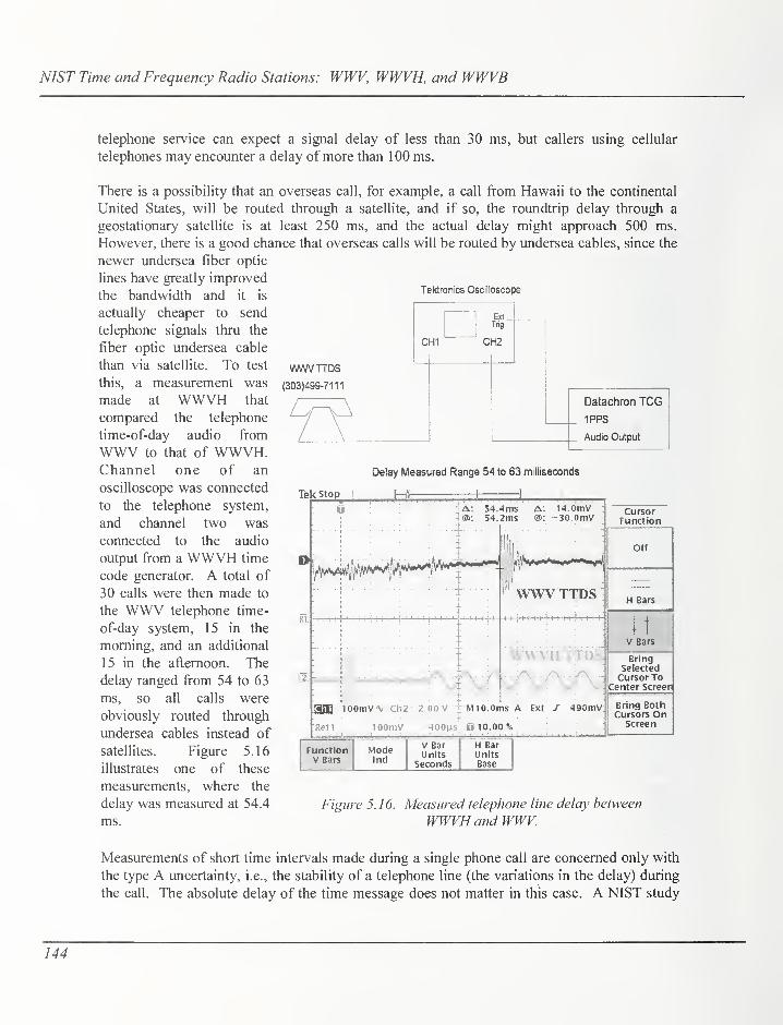
NIST Time and Frequency Radio Stations: WWV, WWVH, and WWVB
telephone service can expect a signal delay of less than 30 ms, but callers using cellular
telephones may encounter a delay of more than 100 ms.
Tektronics Oscilloscope
WWVTTDS
(303)499-7111
CHI
Ext_Trig.
CH2
Datachron TCG
1PPS
Audio Output
Delay Measured Range 54 to 63 milliseconds
Tekstop
There is a possibility that an overseas call, for example, a call from Hawaii to the continental
United States, will be routed through a satellite, and if so, the roundtrip delay through a
geostationary satellite is at least 250 ms, and the actual delay might approach 500 ms.
However, there is a good chance that overseas calls will be routed by undersea cables, since the
newer undersea fiber optic
lines have greatly improved
the bandwidth and it is
actually cheaper to send
telephone signals thru the
fiber optic undersea cable
than via satellite. To test
this, a measurement was
made at WWVH that
compared the telephone
time-of-day audio from
WWV to that of WWVH.Channel one of an
oscilloscope was connected
to the telephone system,
and channel two was
connected to the audio
output from a WWVH time
code generator. A total of
30 calls were then made to
the WWV telephone time-
of-day system, 15 in the
morning, and an additional
15 in the afternoon. The
delay ranged from 54 to 63
ms, so all calls were
obviously routed through
undersea cables instead of
satellites. Figure 5.16
illustrates one of these
measurements, where the
delay was measured at 54.4
ms.
0 a: 54.4ms A: I4.0mvt®: S4.2ms @: -30.0mV
+
Bin 1 0OmV \ Ch2 2.00 V
WWVTTDS
WWVHTTDS
MIO.Oms A Ext J 490mV
Refl lOOinV 400|JS U 10.00%
CursorFunction
Off
H Bars
V Bars
BringSelectedCursor To
Center Screen
Bring Botli
Cursors OnScreen
FunctionV Bars
Mode!nd
V BarUnits
Seconds
H BarUnitsBase
Figure 5.16. Measured telephone line delay between
WWVH and WWV.
Measurements of short time intervals made during a single phone call are concerned only with
the type A uncertainty, i.e., the stability of a telephone line (the variations in the delay) during
the call. The absolute delay of the time message does not matter in this case. A NIST study
144

Chapter 5 - Measurement Uncertainties
Table 5.3. Summary ofmeasurement uncertainties.
Measurement Quantity Type A ( 1 d average) 1 ype B
WWV/WWVB transmitted rrequency 1 1/-V-131x10 < 1 X 10"'^
WWVH transmitted frequency 2x10 < 1 X 10
wwv/vvwvri iransmiueu iime <r 1 nn 1-10^ luu ns ^ DU I^S
WWVB transmitted time < 100 ns < 20 |is
WWV/WWVH received frequency 1 X 10"^1 X 10-'°
WWVB received frequency ~5 X 10-'^ < 1 X 10"'^
WWV/WWVH received time < 1 ms 1 ms *
WWVB received time < 1 ^s 100 ^s *
Telephone transmitted time < 100 ns < 100 \is
Telephone received time (landline) 1 ms <30ms
* when corrected for path delay
involving the Automated Computer Time Service (ACTS) [36, 38], a service that sends a
digital time code over telephone lines, showed phone line stability at x = 1 s to be better than
0.1 ms over both a local phone network, and a long distance network between Boulder,
Colorado and WWVH in Kauai [80]. While it is not possible to guarantee this stability during
all phone calls, it is probably safe to say that the 2a stability should be much less than 1 msduring a typical call, which are limited to about 3 minutes in length.
The type B uncertainty does matter when longer time intervals are measured with two phone
calls; a typical scenario during stopwatch calibrations, where the watch might be run for
several hours. For example, the first call is made to obtain the signal to start the stopwatch, and
the second call is made to obtain the signal to stop the stopwatch [57]. If both calls are routed
through the same phone circuit, the delay through the circuit (type B uncertainty) should be the
same for both calls. In practice, the delays will not be identical, and a "time step" will be
introduced. However, the customer can normally assume that the time step will be a few
milliseconds or less in magnitude.
F. Summary of Measurement UncertaintiesTable 5.3 includes estimates of the station and telephone time signal uncertainties as
transmitted and as received, based on the information presented in the previous sections of
Chapter 5. The Type A uncertainties are 2a values obtained using the Allan deviation or a
similar statistic. They are essentially equivalent to the stability of the broadcasts at an
averaging time of 1 d. The Type B uncertainties are systematic. They are related to the
145

NIST Time and Frequency Radio Stations: WWV, WWVH, and WWVB
accuracy of the broadcast with respect to UTC(NIST), and are obtained by non statistical
means, such as adding together the various components of station delays. The combined
measurement uncertainty can be thought of as the Type B uncertainty, plus or minus the Type
A uncertainty.
G. Establishing Traceability to UTC(NIST)The time and frequency broadcasts described in this booklet are referenced to and controlled by
UTC(NTST), the United States national standard for time and frequency. Therefore customers
can use the NIST broadcasts to establish traceability through UTC(NIST) back to the
International System of units (SI). In order to establish traceability, customers must document
each link of the traceability chain and specify the uncertainty for each link [81, 38]. The
uncertainty information provided in this chapter and summarized in Table 5.3 can be used as a
guideline when estimating the uncertainty of the various links, but the actual uncertainties will
vary depending upon the receiving equipment and the calibration methods used. Figure 2.1
illustrates the part of the traceability chain that extends from the SI second down to the NISTtime and frequency services, including the radio stations described in this publication.
146
References
References
1] W. F. Snyder and C. L. Bragaw, Acheivement in Radio: Seventy Years of Radio Science,
Technology, Standards and Measurement at the National Bureau of Standards, Natl. Inst. Stand.
Technol. Spec. Publ. 555, October 1986, 863 pp.
2] J. H. Dellinger, Reducing the Guesswork in Tuning, Radio Broadcast 16, 241-245, December 1923.
(available at: http://tf.nist.gov/general/pd&'757.pdf)
;3] H. J. Walls, The Standard Frequency Set at WWV, QST 8(10), 9-12, October 1924. (available at:
http://tf.nist.gov/general/pdf/1054.pdf)
[4] R. T. Cox, Standard radio wavemeter. Bureau of Standards type R70B, J. Opt. Soc. Amer. 6, 162-
168, March 1922. (available at: http://tf.nist.gov/general/pdf/730.pdf)
[5] E. L. Hall, The Standard Wavemeters of the Bureau of Standards, Sibley J. Eng. 38 (5), 123-126,
May 1924. (available at: http://tfnist.gov/general/pdfl053.pdf)
[6] J. H. Dellinger, The Status of Frequency Standardization, Proc. IRE 16, 579-592, May 1928.
(available at: http://tf.nist.gov/general/pdf/1604.pdf)
[7] H. H. Henline, The Pacific Coast Standard Frequency Station 6XBM, QST 9, 26, November 1925.
[8] Possible discontinuance of radio signal transmission of standard frequency. Radio Service Bull. No.
109, 13, April 1926. (available at: http://tf.nist.gov/general/pdf/1906.pdf)
[9] L. Mickey and A. D. Martin, Development of Standard Frequency Transmitting Sets, Nat. Bur.
Stand. (U. S.) J. Res. 12, 1-12, January 1934. (available at: http://tf.nist.gov/general/pdf71616.pdf)
[10] Uses of Transmissions of Standard Radio Frequencies, Nat. Bur. Stand. (U. S.) Letter Circ. 335,
October 1932, 18 pp. (available at: http://tf.nist.gov/general/pdf/1613.pdf)
[11] J. H. Dellinger and E. L. Hall, Radio dissemination of the national standard of frequency. Radio
Engineering 12, 23, May 1932. (available at: http://tf.nist.gov/general/pdf/1907.pdf)
[12] W. D. George, WWV Standard Frequency Broadcasts, FM and Television 7, 25-27, 44, June 1947.
(available at: http://tf.nist.gov/general/pdf/1625.pdf)
[13] T. Jones, Splitting the Second: The Story of Atomic Time, Institute of Physics Publishing, Bristol,
UK (2000), pp. 123-126.
[14] Experimental Timing Code Added to WWV Broadcasts, NBS Tech. News Bull. 44, 1 14-115, July
1960. (available at: http://tf.nist.gov/general/pdC1670.pdf)
147

NIST Time and Frequency Radio Stations: WWV, WWVH, and WWVB
[15] Changes in WWV/WWVH Standards Broadcasts, Nat. Bur. Stand. (U.S.) Tech. News Bull. 45, 1 1-
13, January 1961. (available at: http://tf.nist.gov/general/pdf/1684.pdf)
[16] NBS Frequency and Time Broadcast Services, Nat. Bur. Stand. (U.S.) Spec. Publ. 236, July 1971,
17 pp. (available at: http://tf.nist.gov/general/pdf/1771.pdf)
[17] Y. Beers, WWV moves to Colorado, Parts 1 and II, QST, 11-14, January 1967, 30-36, February
1967. (available at: http://tfnist.gov/general/pdf271.pdf)
[18] Improvements in the NBS Primary Standard of Frequency, Nat. Bur. Stand. (U.S.) Tech. News Bull.
37, 8-12, January 1953. (available at: http://tf.nist.gov/general/pdf/1636.pdf)
[19] G. H. Lester, Experimental Standard-Frequency Transmitting Station, WWVH, Communications
29, 20-23, September 1949. (available at: http://tfnist.gov/general/pdf71629.pdf)
[20] Improvements in Standard Frequencies Broadcast by Radio Stations WWV and WWVH, Nat. Bur.
Stand. (U.S.) Tech. News Bull. 40, 37-38, March 1956. (available at:
http://tfnist.gov/general/pdf/1641.pdf)
[21] Standard Frequency and Time Signals from NBS Stations WWV and WWVH, Nat. Bur. Stand.
(U.S.) Misc. Publ. 236, July 1961, 8 pp. (available at: http://tfnist.gov/general/pdf/1681.pdf)
[22] Standards Frequency and Time Services of the National Bureau of Standards, Nat. Bur. Stand.
(U.S.) Misc. Publ. 236, January 1965, 12 pp. (available at: http://tfnist.gov/general/pdC1718.pdf)
[23] New WWVH Facility, Nat. Bur. Stand. (U.S.) Tech. News Bull. 54, 137, June 1970. (available at:
http ://tfnist.gov/general/pdf/ 1 767 .pdf)
[24] L. Fey, New Signals from an Old Timer ... WWV, Broadcast Engineering 13, 44-46, July 1971.
(available at: http://tfnist.gov/general/pdf479.pdf)
[25] W. D. George, Low Frequency Standards Transmissions, Proc. 1957 Frequency Control
Symposium, (April 1957), 574-585. (available at: http://tfnist.gov/general/pdf71535.pdf)
[26] Experimental Standard Frequency Broadcast on 60 Kilocycles, Nat. Bur. Stand. (U.S.) Tech. NewsBull. 41, 99-100, July 1957. (available at: http://tfnist.gov/general/pdf/1649.pdf)
[27] New Standard Frequency Broadcasts, Nat. Bur. Stand. (U.S.) Tech. News Bull. 44, 120-121, July
1960. (available at: http://tfnist.gov/general/pdf/1671.pdf)
[28] B. E. Blair and A. H. Morgan, Control of WWV and WWVH Standard Frequency Broadcasts by
VLF and LF Signals, Nat. Bur. Stand. (U.S.) Radio Sci. J. Res. 69D, 323-336, July 1965. (available
at: http://tfnist.gov/general/pdf/1724.pdf)
[29] New Facilities Dedicated for WWVB and WWVL, Nat. Bur. Stand. (U.S.) Tech. News Bull. 47,
178-180, October 1963. (available at: http://tfnist.gov/general/pdf/1707.pdf)
[30] J. M. Richardson, Establishment ofNew Facilities for WWVL and WWVB, Nat. Bur. Stand. (U.S.)
Radio Sci. J. Res. 68D, 135, January 1964. (available at: http://tfnist.gov/general/pdC1710.pdf)
148
References
[31] R. Brown, Fort Collins Becoming World's Time Center, Fort Collins Coloradoan, 8A, November 7,
1965.
[32] WWVB adds Time Code to Broadcast, NBS Tech. News Bull. 50, 15-16, January 1966. (available
at: http://tf.nist.gOv/generai/pdf/l 73 1 .pdf)
[33] M. Deutch, D. W. Hanson, G. Nelson, C. Snider, D. Sutton, W. Yates, P. M. Hansen, and B.
Hopkins, WWVB Improvements: New Power From An Old Timer, Proc. 1999 Precise Time and
Time Interval Meeting (PTTI), December 1999, 523-535. (available at:
http://tfnist.gov/general/pdf/1406.pdf)
[34] P. P. Viezbicke, NBS Frequency-Time Broadcast Station WWV, Fort Collins, Colorado, Nat. Bur.
Stand. (U.S.) Tech. Note 611, October 1971, 33 pp. (available at:
http://tfnist.gov/general/pdf/ 1 420.pdf)
[35] Valcom Limited, Valcom Antenna Installation Manual, Guelph, Ontario, Canada, 2000.
[36] J. Levine, M. A. Lombardi, and A. N. Novick, NIST Computer Time Services: Internet Time
Service (ITS), Automated Computer Time Service (ACTS), and time.gov Web Sites, Natl. Inst.
Stand. Technol. Spec. Publ. 250-59, May 2002, 79 pp. (available at:
http://tfnist.gOv/general/pdf/l 55 1 .pdf)
[37] M. A. Lombardi, Remote Frequency Calibrations: The NIST Frequency Measurement and Analysis
Service, Natl. Inst. Stand. Technol. Spec. Publ. 250-29, June 2004, 90 pp. (available at:
http://tfnist.gov/general/pdf/I950.pdf)
[38] M. A. Lombardi, NIST Time and Frequency Services, Natl. Inst. Stand. Technol. Spec. Publ. 432,
January 2002, 80 pp. (available at: http://tfnist.gov/general/pdf/1383.pdf)
[39] Timing Committee, Telecommunications and Timing Group. IRIG Serial Time Code Formats.
Secretariat, Range Commanders Council, U.S. Army White Sands Missile Range, New Mexico.
IRIG Standard 200-98, May 1998. 51 pp.
[40] Stewart, J. W. Navy Electricity and Electronics Training Series (NEETS), Module 10: Introduction
to Wave Propagation, Transmission Lines, and Antennas. Naval Education and Training Program
Development Center, Pensacola, Florida. 1983 ed., 191 pp.
[41] Collins Radio Company. Broadband HF Monopole Antenna, Model 437C Instruction Book.
Collins Radio Company, Dallas Division, Dallas, Texas. June 1964. 46 pp.
[42] P. M. Hansen and J. Birkett, WWVB Year 2000: Post Upgrade Baseline, Space and Naval Warfare
Systems Center (SSC San Diego) Technical Report 1833, December 2003, 46 pp.
[43] P. M. Hansen and D. Gish, WWVB Post Repair: Antenna Performance Measurement, Space and
Naval Warfare Systems Center (SSC San Diego) Technical Report 1834, December 2003, 32 pp.
[44] P. M. Hansen and D. Gish, WWVB Antenna and Antenna Tuning System: Baseline Measurements,
Naval Command, Control and Ocean Surveillance Center, RDT&E Division. Tech. Rep. 1693,
February 1995, 66 pp.
149

NIST Time and Frequency Radio Stations: WWV, WWVH, and WWVB
[45] Rough estimates obtained from BBC and Voice of America reports about shortwave radio
listenership.
[46] Data compiled from correspondence with leading manufacturers of radio controlled clock
components.
[47] J. B. Milton, WWVB/WWVL Field Studies, Nat. Bur. Stand. (U.S.) Rep. 9725, March 1969, 131
pp. (available at: http://tf.nist.gov/general/pdf/458.pdf)
[48] P. M. Hansen and D. Gish, WWVB Baseline Measurements: Summary, Findings and
Recommendations, Naval Command, Control and Ocean Surveillance Center, RDT&E Division.
Tech. Rep. 1692, February 1995, 26 pp.
[49] J. M. Birkett, Technique for Building and Calibration VLF/LF Receive Loop Antennas, Naval
Command, Control and Ocean Surveillance Center, RDT&E Division. Tech. Rep. 1742, April 1997,
February 1995, 25 pp.
[50] J. A. Barnes and R. E. Beehler, Report on the 1975 Survey of Users of the Services of Radio
Stations WWV and WWVH, Nat. Bur. Stand. (U.S.) Tech. Note 674, October 1975, 93 pp.
(available at: http://tfnist.gov/general/pdfl89.pdf)
[5 1 ] International Telecommunication Union (ITU), Standard Frequencies and Time Signals, Reports of
the CCIR, 1990: Annex to Volume VII, Geneva, 1990, 89-100.
[52] J. P. Lowe, Results of 2001 Customer Satisfaction Survey, September 2001. (available at:
http://tf.nist.gov/survey/survey.htm)
[53] C. W. Stevens, Los Angeles County Taps Atomic Clock to Improve the Timing of Its Stoplights,
Wall Street Journal, November 7, 1988.
[54] Radio Navigation Aids, Natl. Imagery and Mapping Agency (NIMA) Pub. 1 17, 2002.
[55] A. S. Risley, The National Measurement System for Time and Frequency, Nat. Bur. Stand. (U.S.)
Spec. Publ. 445-1, June 1976,74 pp. (available at: http://tf.nist.gov/general/pdf88.pdf)
[56] The International Occultation Timing Association (IOTA) web site, (available at http://www.lunar-
occultations.com/iota)
[57] J. C. Gust, R. M. Graham, and M. A. Lombardi, Stopwatch and Timer Calibrations, Natl. Inst.
Stand. Technol. Spec. Publ. 960-12, May 2004, 60 pp. (available at:
http://tfnist.gov/general/pdf/1930.pdf)
[58] J. T. Stanley, The Use and Limitations of HF Standard Broadcasts for Time and Frequency
Comparisons, Proc. 1972 Precise Time and Time Interval Meeting (PTTI), November 1972, 249-
258. (available at: http://tfnist.gov/general/pdf/534.pdf)
[59] R. R. Stone, Jr., Synchronization of Local Frequency Standards with VLF Transmissions, Proc.
1962 IEEE Frequency Control Symposium, 227-240.
150

References
[60] G. Kamas and M. A. Lombardi, Time and Frequency User's Manual, Natl. Inst. Stand. Techno!.
Spec. Publ. 559, September 1990, 164 pp. (available at: http://tf.nist.gov/generai/pdf/461.pd0
[61]M. A. Lombardi, L. M. Nelson, A. N. Novick, and V. Z. Zhang, Time and Frequency Measurements
Using the Global Positioning System (GPS), Cal Lab Int. J. Metrology 8, 26-33, July-September
2001. (available at: http://tfnist.gov/general/pdf/1424.pdf)
[62] Federal Communications Commission Rule 73.1545.
[63] Standard Musical Pitch, NBS Tech. News Bull. 41, 120-121, August 1957. (available at:
http://tfnist.gov/general/pdf/I650.pdf)
[64] D. W. Allan and F. H. Brzoticky, Calibration of Police Radar Instruments, Report of the 60"'
National Conference on Weights and Measures, Natl. Bur. Stand. Spec. Publ. 442, May 1976, 42-47.
(available at: http://tfnist.gov/general/pdf/87.pdf)
[65] W. L. Young, Legal Calibration (Certification) of Police Traffic Control Devices, Proc. 1998 Natl.
Conf Stand. Lab., 199-201.
[66] R. L. Fey, J. B. Milton, and A. H. Morgan, Remote Phase Control of Radio Station WWVL, Nature
193, 1063-1064, March 1962. (available at: http://tfnist.gov/general/pdC477.pdf)
[67] Commercial Television Aids NBS Standard Broadcasts, NBS Tech. News Bull. 53, 111, May 1969.
(available at: http://tfnist.gov/general/pdfl757.pdf)
[68] D. W. Allan and M. A. Weiss, Accurate Time and Frequency Transfer During Common-View of a
GPS Satellite, Proc. 1980 IEEE Frequency Control Symposium, 334-346. (available at: http://
tfnist.gov/general/pdf/1 92.pdf)
[69] D. D. Davis, M. A. Weiss, A. J. Clements, and D. W. Allan, Construction and Performance
Characteristics of a Prototype NBS/GPS Receiver, Proc. 1981 IEEE Frequency Control Symposium,
546-552. (available at: http://tfnist.gov/general/pdf/558.pdf)
[70] D. W. Hanson, Fundamentals of Two-Way Time Transfers by Satellite, Proc. 1989 IEEE Frequency
Control Symposium, 174-178. (available at: http://tfnist.gov/general/pdf/836.pdf)
[71] J. B. Milton, Standard Time and Frequency: Its Generation, Control, and Dissemination by the
National Bureau of Standards, Nat. Bur. Stand. (U.S.) Tech. Note 656, June 1974, 25 pp. (available
at: http://tfnist.gov/general/pdf948.pdf)
[72]NIST Time and Frequency Bulletins are available at:
http://tfnist.gov/pubs/bulletin/timescaleindex.htm
[73] N. Hironaka and C. Trembath, The Use of National Bureau of Standards High Frequency Broadcasts
for Time and Frequency Calibrations, Nat. Bur. Stand. (U.S.) Tech. Note 668, May 1975, 49 pp.
(available at: http://tfnist.gov/general/pdf/453.pdf)
[74] G. Kamas and S. L. Howe, Time and Frequency User's Manual, Nat. Bur. Stand. (U.S.) Spec. Publ.
559, November 1979, 256 pp. (available at: http://tfnist.gov/general/pdfl792.pdf)
151

NIST Time and Frequency Radio Stations: WWV, WWVH, and WWVB
[75] J. J. Carr, Elements of Electronic Instrumentation and Measurement, Prentice Hall, New Jersey, 3rd
ed.,(1996), pp. 439-440.
[76] R. Evans, A Laboratory-Grade 10-MHz Frequency Standard, QEX, 13-21, May/June 2002.
[77] W. F. Bain, Simple Skywave Frequency Calibration Approaching One Part-Per-Billion, QEX, 19-
22, June 1996.
[78] A. H. Morgan, Precise Time Synchronization of Widely Separated Clocks, Nat. Bur. Stand. (U.S.)
Tech. Note 22, July 1959, 72 pp. (available at: http://tf.nist.gov/general/pdfl659.pdf)
[79] D. H. Andrews, C. Chaslain, J. DePrins, Reception of Low Frequency Time Signals, Frequency 6
(9), 13-21, September 1968. (available at: http://tfnist.gov/general/pdfl749.pdf)
[80] D. W. Allan, D. D. Davis, J. Levine, M. A. Weiss, N. Hironka, and D. Okayama, New Inexpensive
Frequency Calibration Service from NIST, Proc. 1990 IEEE Frequency Control Symposium, 107-
1 16. (available at: http://tf.nist.gov/general/pdf889.pdf)
[81] M. A. Lombardi, Traceability in Time and Frequency Metrology, Cal Lab Int. J. Metrology 6, 33-
40, September-October 1999. (available at: http://tfnist.gov/general/pdf/1305.pdf)
152

Technical Publications
Periodical
Journal of Research of the National Institute of Standards and Technology—Reports NIST research and
development in metrology and related fields of physical science, engineering, applied mathematics, statistics,
biotechnology, and information technology. Papers cover a broad range of subjects, with major emphasis on
measurement methodology and the basic technology underlying standardization. Also included from time to time are
survey articles on topics closely related to the Institute's technical and scientific programs. Issued six times a year.
Nonperiodicals
Monographs—Major contributions to the technical literature on various subjects related to the Institute's scientific
and technical activities.
Handbooks—Recommended codes of engineering and industrial practice (including safety codes) developed in
cooperation with interested industries, professional organizations, and regulatory bodies.
Special Publications—Include proceedings of conferences sponsored by NIST, NIST annual reports, and other
special publications appropriate to this grouping such as wail charts, pocket cards, and bibliographies.
National Standard Reference Data Series—Provides quantitative data on the physical and chemical properties of
materials, compiled from the world's literature and critically evaluated. Developed under a worldwide program
coordinated by NIST under the authority of the National Standard Data Act (Public Law 90-396). NOTE: The
Journal of Physical and Chemical Reference Data (JPCRD) is published bimonthly for NIST by the American
Institute of Physics (AlP). Subscription orders and renewals are available fi'om AIP, P.O. Box 503284, St. Louis,
MO 63150-3284.
Building Science Series—Disseminates technical information developed at the Institute on building materials,
components, systems, and whole structures. The series presents research results, test methods, and performance
criteria related to the structural and environmental functions and the durability and safety characteristics of building
elements and systems.
Technical Notes—Studies or reports which are complete in themselves but restrictive in their treatment of a subject.
Analogous to monographs but not so comprehensive in scope or definitive in treatment of the subject area. Often
serve as a vehicle for final reports of work performed at NIST under the sponsorship of other government agencies.
Voluntary Product Standards—Developed under procedures published by the Department of Commerce in Part
10, Title 15, of the Code of Federal Regulations. The standards establish nationally recognized requirements for
products, and provide all concerned interests with a basis for common understanding of the characteristics of the
products. NIST administers this program in support of the efforts of private-sector standardizing organizations.
Order thefollowing NISTpublications—FIPS and NISTIRs—from the National Technical Information Service,
Springfield VA 22161.
Federal Information Processing Standards Publications (FIPS PUB)—Publications in this series collectively
constitute the Federal Information Processing Standards Register. The Register serves as the official source of
information in the Federal Government regarding standards issued by NIST pursuant to the Federal Property and
Administrative Services Act of 1949 as amended. Public Law 89-306 (79 Stat. 1 127), and as implemented by
Executive Order 11717 (38 FR 12315, dated May 1 1,1973) and Part 6 of Title 15 CFR (Code of Federal
Regulations).
NIST Interagency or Internal Reports (NISTIR)—The series includes interim or final reports on work performed
by NIST for outside sponsors (both government and nongovernment). In general, initial distribution is handled by
the sponsor; public distribution is handled by sales through the National Technical Information Service, Springfield,
VA 22161, in hard copy, electronic media, or microfiche form. NISTIRs may also report results ofNIST projects of
transitory or limited interest, including those that will be published subsequently in more comprehensive form.
NIST

U.S. Department of CommerceNational Bureau of Standards and Technology325 BroadwayBoulder, CO 80305-3328
Official BusinessPenalty for Private Use $300


![[XLS] · Web viewESEI Intl Business School Inst Nat Form Agents Santé Canadian University of Dubai Inst Tec Santo Domingo Centro Posgrad Admin Inform AC Univ Advent Rwanda Beijing](https://img.pdfslide.us/doc/110x75/5b0450317f8b9a8c688d6f00/xls-viewesei-intl-business-school-inst-nat-form-agents-sant-canadian-university.jpg)