Embed Size (px)
Citation preview

NASA’s New Spacecraft: OrionThe Orion spacecraft will launch aboard the Space Launch System (SLS). Together they will serve as our nation’s next generation exploration vehicles transporting transport humans to asteroids, the moon, Lagrange points –– and ultimately to Mars.
Drawing from more than 50 years of
spaceflight research and experience, Orion features
dozens of technology innovations and advancements such as
unique life support, propulsion, thermal protection and avionics systems.
These advanced systems will support long-duration deep space missions, and
bring future crews home safely.
The spacecraft includes a crew module, a service module, a spacecraft connector, and a
launch abort system which ensures the safety of the crew during an emergency on the launch
pad or during ascent. The crew module can support up to four astronauts for short or
long-duration spaceflight missions. The service module is the powerhouse that fuels and
propels the spacecraft. It also stores the life-sustaining air and water that astronauts
need during space travel. Additionally, the service module’s structure will provide
areas to mount scientific experiments and cargo.
The Orion and SLS will take astronauts farther into the solar system than
ever before, continuing America’s journey of discovery.
To learn more about human spaceflight at NASA visit:www.nasa.gov/exploration
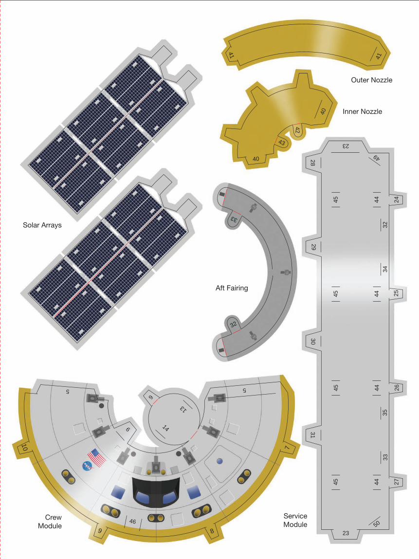
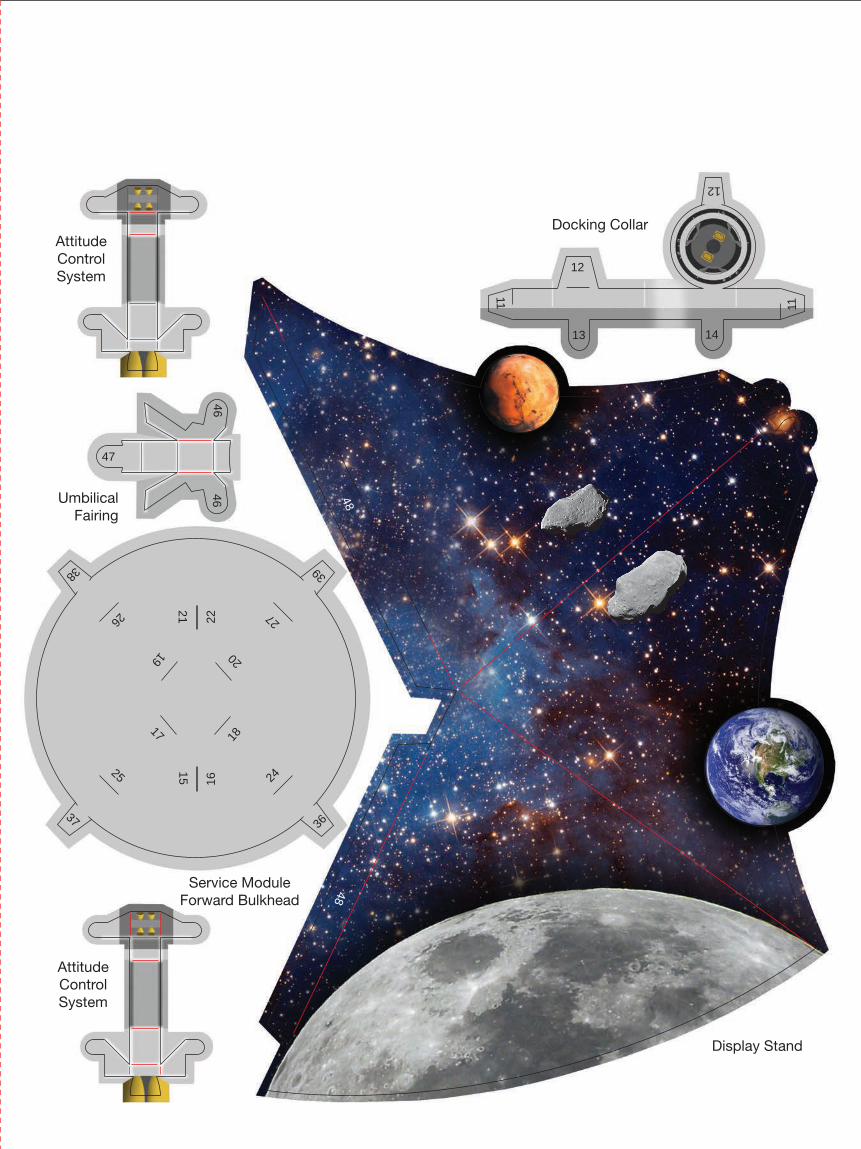
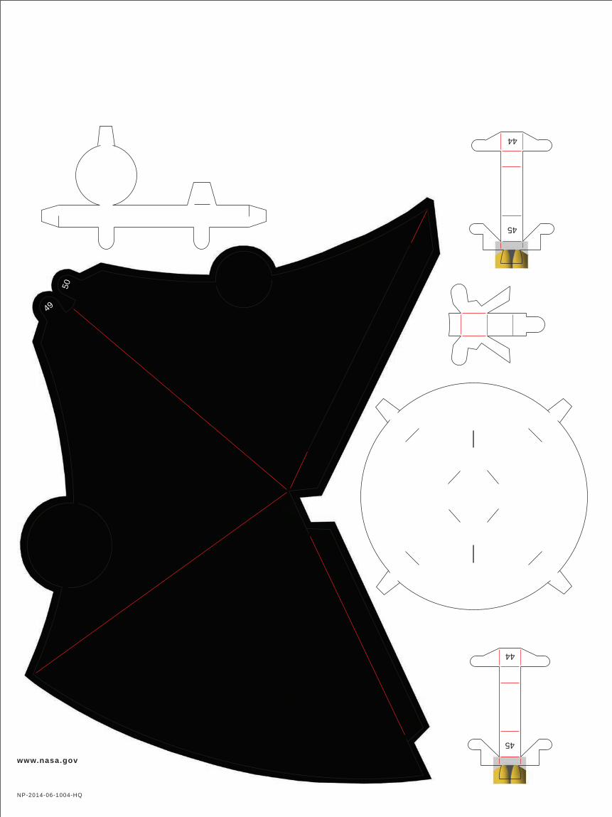
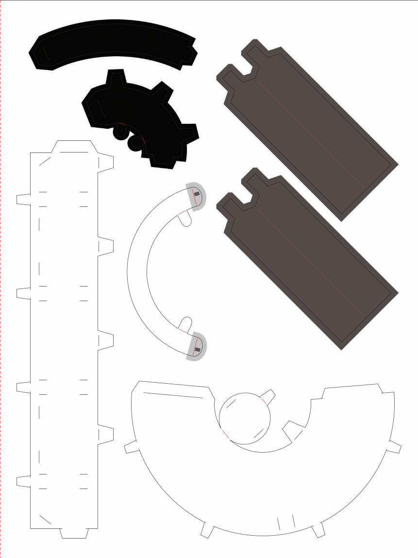
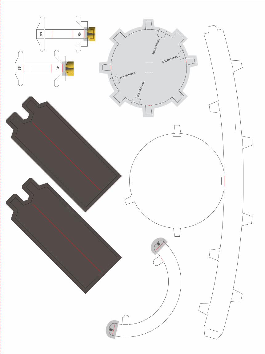
Step-by-Step Assembly DiagramFollowing these steps, align numbered tabs to their corresponding locations in consecutive order.
Docking Collar
Crew Module
Crew Module Fairing
Service Module
Service Module Aft Bulkhead
Solar Array (4)
Service Module For-ward Bulkhead
Crew Module Assembly from Step 1
Aft Fairing with High Gain
Antenna
Aft FairingOuter Nozzle(Black on inside)
Inner Nozzle(Black on inside)
Umbilical Fairing
Display Stand
Starfield/planets on inside surface
Twist planets outward slightly. Do not break off!
Carefully insert Display Stand into two slits under-neath model
Attitude Control System (4)
1 2 3
54Fold each solar panel in half and tape together. Tape the 4 solar panels to the inside of Service Module Aft Bulkhead before attaching the Aft Bulkhead to the Service Module.

36
3738
39
1
1
2
3
4
3
42
78
9
10
28
29
30
31
35
34
4243
47
Solar Arrays
Aft Fairing
Service Module Aft Bulkhead
Crew Module Fairing
Attitude Control System
Attitude Control System
36
3738
39
7
89
10
40
40
41
41
43
5 5
6
6
13
14
23
23
2425
2627
3130
2829
32
33
3233
3435
46
49
50
Solar Arrays
Outer Nozzle
Inner Nozzle
Service Module
Crew Module
Aft Fairing7
89
10
40
40
41
41
42
43
4445
4445
4445
4445
11 11
12
12
13 14
15
2018
1719
1622
21
24
27
25
26
36
37
38 39
4646
47
4848Umbilical
Fairing
Docking Collar
Display Stand
Service Module Forward Bulkhead
Attitude Control System
Attitude Control System
www.nasa.gov
NP-2014-06-1004-HQ
44
45
44
45
49
50
46
46
44 45
44 45
46
46
SOLAR PANEL
SOLAR PANEL
SO
LAR
PA
NEL
SO
LAR
PA
NEL
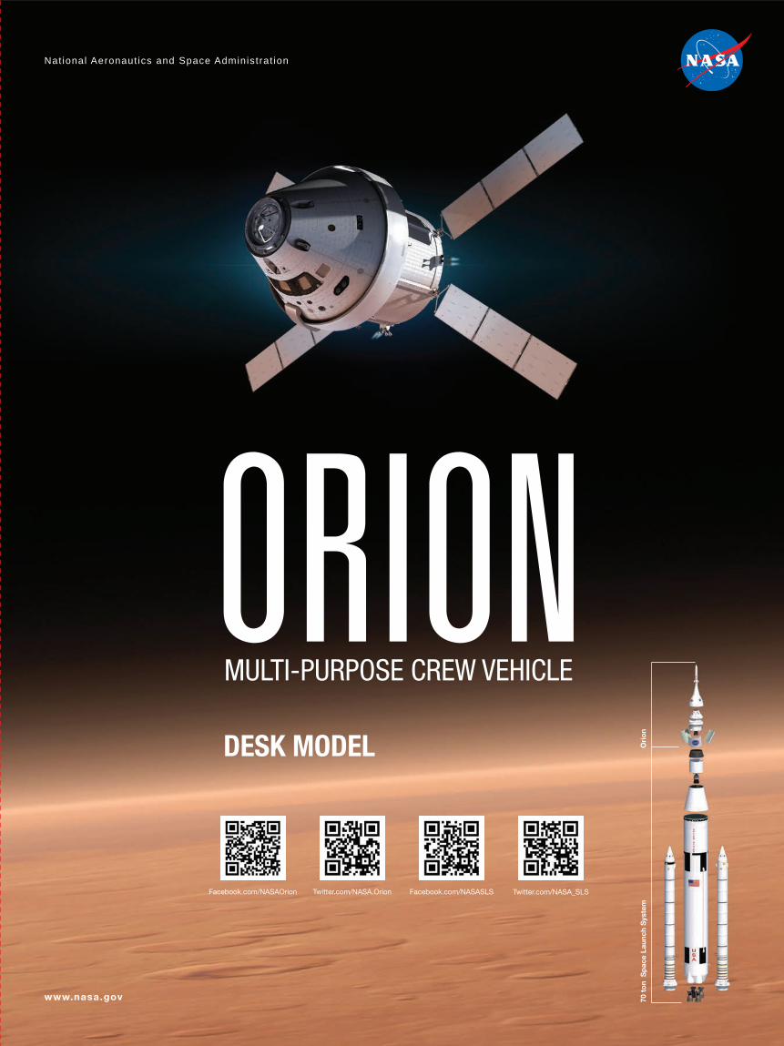
ORION
National Aeronaut ics and Space Administrat ion
www.nasa.gov
MULTI-PURPOSE CREW VEHICLE
DESK MODEL
70 t
on
Sp
ace
Laun
ch S
yste
m
Ori
on
Facebook.com/NASAOrion Twitter.com/NASA.Orion Facebook.com/NASASLS Twitter.com/NASA_SLS