Embed Size (px)
Citation preview

NASA/ASEE SUMMER FACULTY RESEARCH FELLOWSHIP PROGRAM
MARSHALL SPACE FLIGHT CENTER
THE UNIVERSITY OF ALABAMA
FUEL OPTIMAL MANEUVERS OF SPACECRAFT
ABOUT A CIRCULAR ORBIT
Prepared By: Thomas E. Carter, Ph°D.
Academic Rank: Associate Professor
University and Department: Eastern Connecticut State CollegeMathematical Sciences
NASA/MSFC:Division:Branch:
Control Systems DivisionDynamics & Trajectory Analysis
Branch
MSFC Counterpart: Harry J. Buchanan
Date: August 20, 1982
Contract No. NGT 01-002-099The University of Alabama
xl-i
https://ntrs.nasa.gov/search.jsp?R=19830009099 2019-03-21T16:30:10+00:00Z
FUEL OPTIMAL MANEUVERS OF SPACECRAFT
ABOUT A CIRCULAR ORBIT
By
Thomas E. Carter
Associate Professor of Mathematical Sciences
Eastern Connecticut State College
Willimantic, Connecticut
ABSTRACT
Fuel optimal maneuvers of spacecraft relative to a body in circular orbit
are investigated using a point mass model in which the magnitude of the thrust
vector is bounded. All nonsingular optimal maneuvers consist of intervals of
full thrust and coast and are found to contain at most seven such intervals in
one period. Only four boundary conditions where singular solutions occur are
possible. Computer simulation of optimal flight path shapes and switching
functions are found for various boundary conditions. Emphasis is placed on the
problem of soft rendezvous with a body in circular orbit.
XI-ii

ACKNOWLEDGEMENTS
The author expresses appreciation to Stan Carroll of the Dynamics and
Trajectory Analysis Branch of the George C. Marshall Space Flight Center
whose suggestions and insights were of much value to this project. He also
thanks Roger Burroughs of the Flight Mechanics Branch of the George C. Marshall
Space Flight Center who wrote the computer program which was used to solve the
two-point-boundary value problems and who instructed the author in the use of
this program.
XI-iii
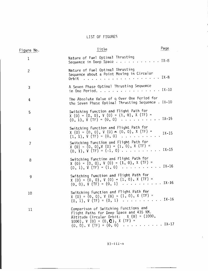
LIST OF FIGURES
Figure No.
1
6
7
8
i0
ii
Title Pa_ge-
Nature of Fuel Optimal ThrustingSequence in Deep Space ........... IX-8
Nature of Fuel Optimal ThrustingSequence about a Point Moving in CircularOrbit ................... IX-8
A Seven Phase Optimal Thrusting Sequencein One Period ................ IX-IO
The Absolute Value of q Over One Period forthe Seven Phase Optimal Thrusting Sequence IX-IO
Switching Function and Flight Path forX (0) = (0, 0), V (0) = (1, 0), X (TF) =(0, 1), V (TF) = (0, O) .......... IX-15
Switching Function and Flight Path forX (0) = (0, 0), V (0) : (0, 0), X (TF) =(I, 1), V (TF) = (0, O) ..........
IX-15
Switching Function and Flight Path forX (0) = (0, O)_V (0) = (i, 0), X (TF) =(0, 1), V (TF) = (-i, O) .......... IX-15
Switching Function and Flight Path forX (0) = (0, 0), V (0) = (1, 0), X (TF) =(0, 1), V (TF) = (1, O) .......... IX-16
Switching Function and Flight Path forX (0) = (0, 0), V (0) = (1, 0), X (TF) =(0, 0), V (TF) = (0, I) .......... IX-16
Switching Function and Flight Path forX (0) = (0, 0), V (0) = (I, 0), X (TF) =(0, i), V (TF) = (0, I) .......... IX-16
Comparison of Switching Functions andFlight Paths for Deep Space and 435 KM.Altitude Circular Orbit: X (0) = (1000,I000), V (0) = (0,_), X (TF) =(0, 0), V (TF) = (0, O) .......... IX-17
Xl-iii-a
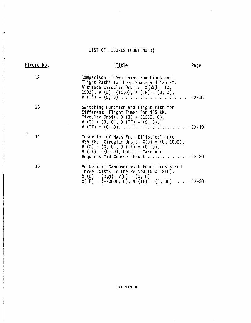
LIST OF FIGURES (CONTINUED)
Figure No.
12
13
15
Title Page
Comparison of Switching Functions and
Flight Paths for Deep Space and 435 KM.
Altitude Circular Orbit: X(O) = (0,I000), V (0) =(I0,0), X (TF) = (0, 0),
V (TF) = (0, O) .............. IX-18
Switching Function and Flight Path for
Different Flight Times for 435 KM.
Circular Orbit: X (0) = (1000, 0),V (0) = (0, 0), X (TF) = (0, 0),
V (TF) = (0, O) ............... IX-IB
Insertion of Mass From Elliptical into
435 KM. Circular Orbit: X(O) = (0, 1000),
V (0) = (0, 0), X (TF) = (0, 0),
V (TF) -- (0, 0), Optimal Maneuver
Requires Mid-Course Thrust ......... IX-20
An Optimal Maneuver with Four Thrusts and
Three Coasts in One Period (5600 SEC):
X (0) = (0,0), V(O) = (0, O)X(TF) = (-73000, 0), V (TF) = (0, 35) IX-20
Xl-iii-b

Io
II.
III.
IV.
CONTENTS
FUEL OPTIMAL MANEUVERS OF SPACECRAFT ABOUT A CIRCULAR ORBIT
Introduction
Mathematical Analysis
I. Solutions in the Orbital Plane
2. Solutions Out of the Orbital Plane
Computer Simulations
Conclusions
Xl-iv

I. INTRODUCTION
Most of the immediate applications of space involve a body in circular
orbit. Fuel optimal maneuvers of a spacecraft relative to such a body constitute
the subject of this investigation.
We assume the spacecraft to be a point mass with a variable thrust vector
of bounded magnitude. The mass of the spacecraft is assumed constant over a
fixed flight time tf and a minimum fuel maneuver will be regarded as a maneuver
in which the integral of the magnitude of the thrust is minimized. The position
x and velocity v of the spacecraft are relative to a coordinate system fixed in
the rotating body whose angular speed is _. The positive x I axis is in the
direction of the orbital velocity, the positive x 2 axis is toward the center,
and the positive x 3 axis completes a right handed system. Relative to this
coordinate system, the acceleration of the spacecraft is determined by the
applied thrust, a coriolis acceleration, and a centrifugal acceleration.
The case where _ = 0 is equivalent to the problem of fuel optimal maneuvers
relative to a fixed point in deep space. This problem of minimum fuel translation
or its mathematical equivalent, minimum fuel rotation, has been discussed by
several authors [1-5] and is a special case of other second order linear systems
that have been studied [6, 7]. It is well known that the nonsingular solutions
of this problem consist of intervals of full thrust and coast with at most one
coast interval. Minimum fuel control of other and more general linear systems
have been investigated [8-12] and, in general, the solutions are not so
restrictive. The nonsingular fuel optimal solutions for the case where _ _ 0
XI-1
have also been found to consist of intervals of full thrust and coast but more
than one coast interval is possible [13]. We extend that result here to show
that as many as three coast intervals can occur for flight times less than or
equal to 2_/_ and more can occur for flight times exceeding one period. We
show also that there are only four boundary conditions for which singular
solutions exist. Finally we present the results of computer simulation of
optimal maneuvers for various boundary conditions.
XI-2

II. MATHEMATICAL ANALYSIS
The problem of minimum fuel maneuvers of a spacecraft about a body moving
in a circular orbit is formulated as follows.
Let U denote the set of all Lebesque measurable functions which map the
real closed interval [0, tf] into the closed unit ball in _3. We seek u_U
to minimize the functional
tfJ[u] : f lu(t) Idt (I)
o
(where I I denotes the Euclidean norm or magnitude) subject to the differential
equations
x(t) : v(t)
_(t) = Ax(t)+Bv(t)+bu(t) (2)
which hold a.e. on [0, tf] and the boundary conditions
x(O) = x 0 x(tf) : xf
v(O) = v 0 v(tf) : vf (3)
where x O, vO, xf, and vf are specified points in _3 and
(oo:)(! o1A : 0 3_ 2 B = a 0 0 (4)
0 0 -_ 0 0 .
The scalar _ is the orbital angular speed of the body in circular orbit and the
scalar b is the maximum thrust magnitude divided by the mass of the spacecraft.
Since the integrand in Eq. l is independent of x and v the Pontryagin
Maximum Principle provides both necessary and sufficient conditions for a minimum
Xl-3
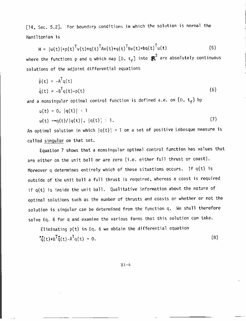
[14, Sec. 5.2]. For boundary conditions in which the solution is normal the
Hamiltonian is
H = lu(t) l+p(t)Tv(t)+q(t)TAx(t)+q(t)TBv(t)+bq(t)Tu(t) (5)
where the functions p and q which map [0, tf] into _3 are absolutely continuous
solutions of the adjoint differential equations
p(t) = -ATq(t)
q(t) = -BTq(t)-p(t) (6)
and a nonsingular optimal control function is defined a.e. on [0, tf] by
u(t) = O, lq(t) I < 1
u(t) =-q(t)/lq(t) I, lq(t)l :, I. (7)
An optimal solution in which lq(t)l = 1 on a set of positive Lebesque measure is
called singular on that set.
Equation 7 shows that a nonsingular optimal control function has values that
are either on the unit ball or are zero (i.e. either full thrust or coast).
Moreover q determines entirely which of these situations occurs. If q(t) is
outside of the unit ball a full thrust is required, whereas a coast is required
if q(t) is inside the unit ball. Qualitative information about the nature of
optimal solutions such as the number of thrusts and coasts or whether or not the
solution is singular can be determined from the function q. We shall therefore
solve Eq. 6 for q and examine the various forms that this solution can take.
Eliminating p(t) in Eq. 6 we obtain the differential equation
• - T-q(t)+B q(t)-ATq(t) = O. (8)
XI-4
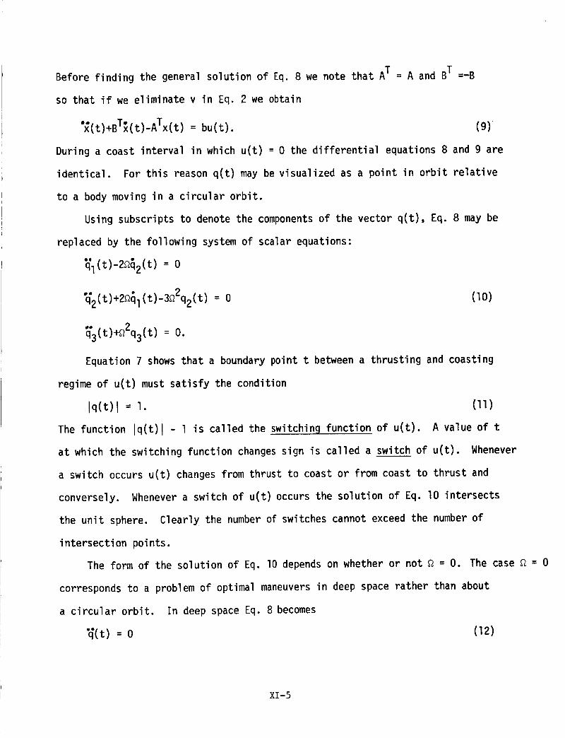
Before finding the general solution of Eq. 8 we note that AT = A and BT =-B
so that if we eliminate v in Eq. 2 we obtain
'_(t)+BT_(t)-ATx(t) = bu(t). (9)_
During a coast interval in which u(t) = 0 the differential equations 8 and 9 are
identical. For this reason q(t) may be visualized as a point in orbit relative
to a body moving in a circular orbit.
Using subscripts to denote the components of the vector q(t), Eq. 8 may be
replaced by the following system of scalar equations:
Q#
ql(t)-2_2(t) = 0
°_2(t)+2_l(t)-3_2q2(t) = 0 (lO)
_3(t)+a2q3(t) = O.
Equation 7 shows that a boundary point t between a thrusting and coasting
regime of u(t) must satisfy the condition
lq(t)l = I. (ll)
The function lq(t)l - l is called the switching function of u(t). A value of t
at which the switching function changes sign is called a switch of u(t). Whenever
a switch occurs u(t) changes from thrust to coast or from coast to thrust and
conversely. Whenever a switch of u(t) occurs the solution of Eq. lO intersects
the unit sphere. Clearly the number of switches cannot exceed the number of
intersection points.
The form of the solution of Eq. I0 depends on whether or not _ = O. The case _ = 0
corresponds to a problem of optimal maneuvers in deep space rather than about
a circular orbit. In deep space Eq. 8 becomes
_(t) = 0 (12)
XI-5

and its general solution is
q(t) = -Pot+qo (0 _ t j tf) (13)
where PO and qo are constants in _3. Geometrically, this solution describes
a straight line segment in _3. This shows, in view of Eq. II, that an optimal
maneuver in deep space can have at most two thrust intervals and one coast interval.
A detailed discussion of this case which also includes singular controls can be
found in [13].
There is more variety in the type of optimal maneuvers that can occur about
a body in circular orbit. In the case where _ _ 0 the general solution of Eq. I0
is
ql(t) = 2 p sin (_t+_)-3clt+c 2
q2(t) = p cos (_t+_)-2c I (0 j t _ tf) (14)
q3(t) = a sin (_t+_)+b cos (_t+@).
Geometrically this solution resembles a helical segment if p, cl, and either a
or b is nonzero. Less general situations can occur which we shall consider. Of
special interest is the case in which a = b = O. In this case the solution curve
is confined to the plane of the circular orbit.
I. Solution in the Orbital Plane
If the third component of each of the vectors xO, vo, xf, and vf in Eq. 3
is zero, then the solutions u(t), q(t), and x(t) from Eqs. 7-9 are each contained
in the orbital plane.
In this case the plane curve obtained from Eq. 14 resembles a type of cycloid
if cI and p are nonzero. The relationship to a cycloid can be demonstrated by the
following transformation.
XI-6

Y1 = -ql/2
Y2 : -q2 •
The curve defined by y = (YI' Y2 ) is a type of cycloid.
following change of variables:
C)= _t+_
= 3c l
2_
c =-3c I - c2 .
2_ 2
the curve takes the standard form
Yl = aC) - p sin @ + c
(15)
If we introduce the
(16)
Y2 = _ - p cos 0 + _/3 (17)
This curve is a cycloid if p = lal and p > O, a prolate cycloid if p > Is] > O,
and a curtate cycloid if 0 < p < lal. In each case the curve is periodic with
a period of 2_. For this reason the curve defined by q is a segment of a periodic
curve having the orbital period 2_/_. It has periodic loops if and only if
p>3lCll >o.2_
The nature of the optimal thrusting sequence is determined by the relationship
of q(t) to the unit circle in the orbital plane. This is depicted in Fig. l for
the case where _ = O. Since a straight line can intersect a circle in at most two
points, it is seen that a fuel optimal maneuver in deep space can have at most two
switches. If _ _ 0 more switches can occur as is demonstrated in Fig. 2 where
q(t) takes a cycloidal shape. There is an essential difference between the deep
space case and the circular orbit case even if tf is small. This is because even
Xl-7

UNIT CIRCLE
/THRUST
q (t)
FIGURE I. NATURE OF FUEL OPTIMAL THRUSTING SEQUENCE
IN DEEP SPACE
COASTTHRUST
TH _/__,,_ q (t)_'__
/ k_°_:>" )
FIGURE 2. NATURE OF FUEL OPTIMAL THRUSTING SEQUENCE ABOUT A
POINT MOVING IN CIRCULAR ORBIT
X_-8
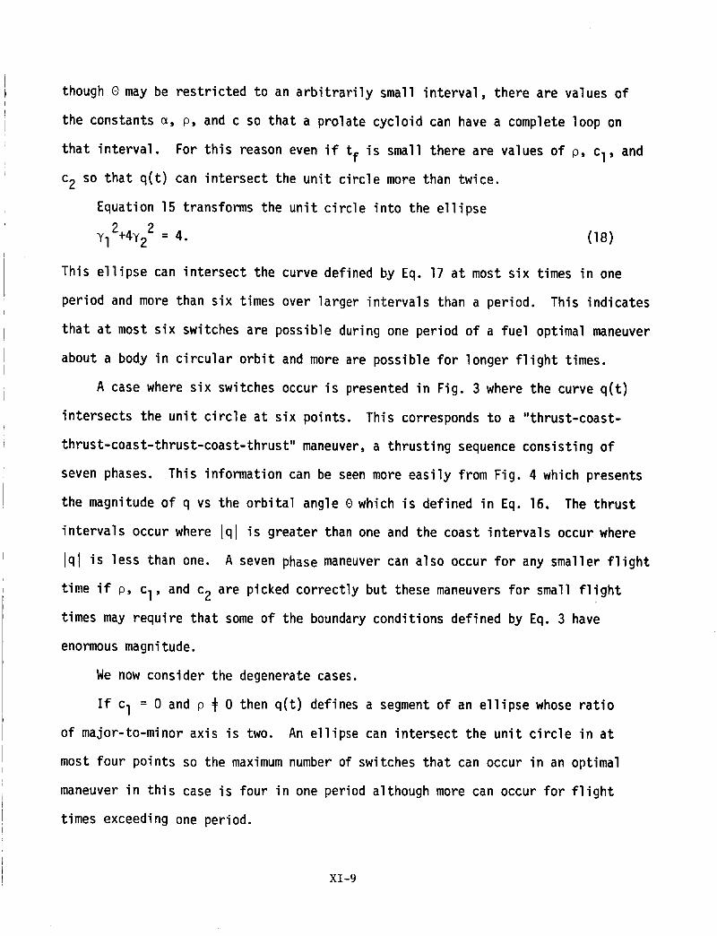
though 0 may be restricted to an arbitrarily small interval, there are values of
the constants _, p, and c so that a prolate cycloid can have a complete loop on
that interval. For this reason even if tf is small there are values of p, cl, and
c2 so that q(t) can intersect the unit circle more than twice.
Equation 15 transforms the unit circle into the ellipse
yl2+4Y2 2 = 4. (18)
This ellipse can intersect the curve defined by Eq. 17 at most six times in one
period and more than six times over larger intervals than a period. This indicates
that at most six switches are possible during one period of a fuel optimal maneuver
about a body in circular orbit and more are possible for longer flight times.
A case where six switches occur is presented in Fig. 3 where the curve q(t)
intersects the unit circle at six points. This corresponds to a "thrust-coast-
thrust-coast-thrust-coast-thrust" maneuver, a thrusting sequence consisting of
seven phases. This information can be seen more easily from Fig. 4 which presents
the magnitude of q vs the orbital angle 0 which is defined in Eq. 16. The thrust
intervals occur where lqlis greater than one and the coast intervals occur where
lql is less than one. A seven phase maneuver can also occur for any smaller flight
time if p, cl, and c2 are picked correctly but these maneuvers for small flight
times may require that some of the boundary conditions defined by Eq. 3 have
enormous magnitude.
We now consider the degenerate cases.
If cI = 0 and p # 0 then q(t) defines a segment of an ellipse whose ratio
of major-to-minor axis is two. An ellipse can intersect the unit circle in at
most four points so the maximum number of switches that can occur in an optimal
maneuver in this case is four in one period although more can occur for flight
times exceeding one period.
XI-9

q2
|.4
4.$
4.4
-4 .$
-| .Q
/\
_r
f
_Je..1 7
\J
j'"-'-'------ -O
-!.$
_._ -I.Q -Q.$ O.I Q.$ I,I I,$
ql
FIGURE 3 : A SEVEN PHASE OPTIMAL THRUSTING SEQUENCE
IN ONE PERIOD
lql
I .?_, -
IIQ 201
DEG
FIGURE 4 " THE ABSOLUTE VALUE OF q OVER ONE PERIOD FORTHE SEVEN PHASE OPTIMAL THRUSTING SEQUENCE
xr- 1o

If p = 0 and cI _ 0 then q(t) defines a straight line segment as in the
deep space situation and at most two switches are possible.
If both Cl and p are zero, no switches can occur. This is the only situation
in the orbital plane case where singular solutions can occur and this happens if
c2 = ±l. This fact will be shown in the material which follows.
2. Solutions Out of the Orbital Plane
We now examine the other cases where q(t) as defined by Eq. 14 is not in the
orbital plane.
We first consider the cases where cI # O.
We note, first of all, that singular solutions are impossible for these cases
because cI _ 0 in Eq. 14 shows that Eq. II cannot be satisfied identically.
If a and b are not both zero and if p is nonzero then the solution of Eq. 14
defines a helical type path that intersects the unit sphere on at most six points
during one period. This establishes at most six switches of u(t) during one period
of an optimal maneuver.
If p = 0 and a and b are not both zero then Eq. 14 defines a shifted sine
curve. This curve can intersect the unit sphere at six points but not more. In
this situation also an optimal maneuver has at most six switches in one period.
We now consider the cases in which cI = O.
Singular solutions occur if and only if Eq. II is satisfied identically, that
is
b2-a 2 = 3p2, ab = O, c2P = O, p2+b2+c22 = I. (19)
Equation 19 is satisfied only in the following cases:
XI-I i
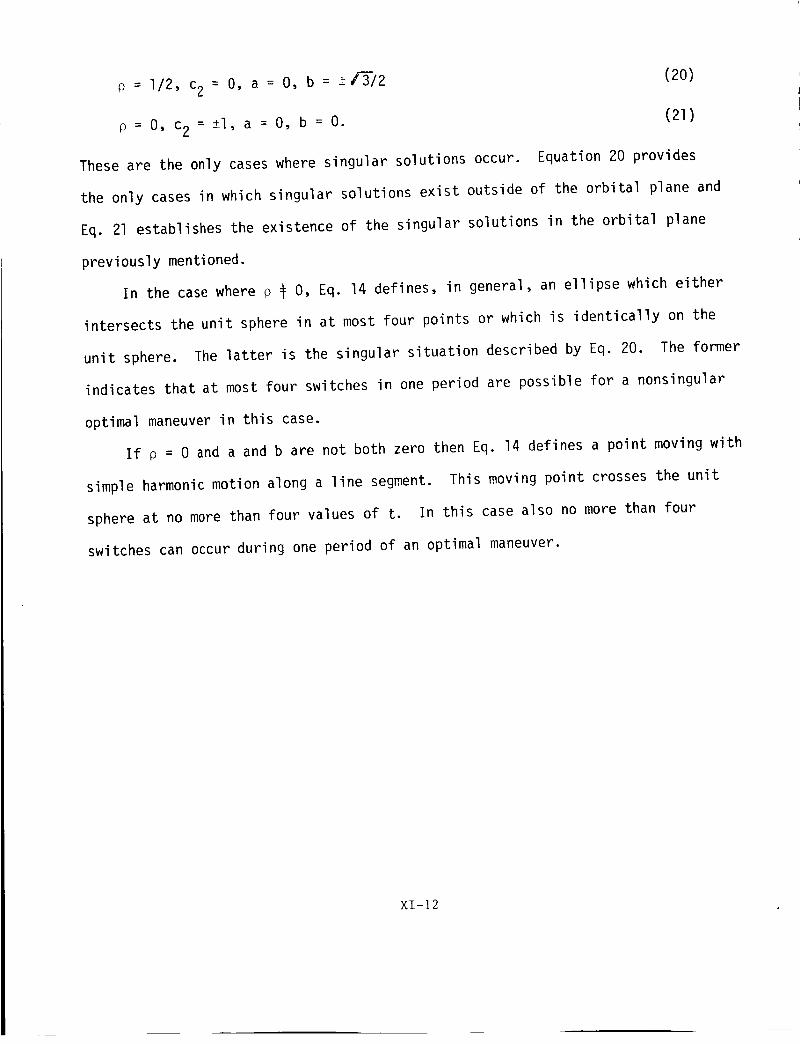
o = I/2, c2 = O, a = O, b = -+f3"/2
p = O, c2 = -+I,a = O, b = O.
These are the only cases where singular solutions occur.
(2O)
(21)
Equation 20 provides
the only cases in which singular solutions exist outside of the orbital plane and
Eq. 21 establishes the existence of the singular solutions in the orbital plane
previously mentioned.
In the case where p _ O, Eq. 14 defines, in general, an ellipse which either
intersects the unit sphere in at most four points or which is identically on the
unit sphere. The latter is the singular situation described by Eq. 20. The former
indicates that at most four switches in one period are possible for a nonsingular
optimal maneuver in this case.
If p = 0 and a and b are not both zero then Eq. 14 defines a point moving with
simple harmonic motion along a line segment. This moving point crosses the unit
sphere at no more than four values of t. In this case also no more than four
switches can occur during one period of an optimal maneuver.
Xl-]2
III. COMPUTER SIMULATIONS
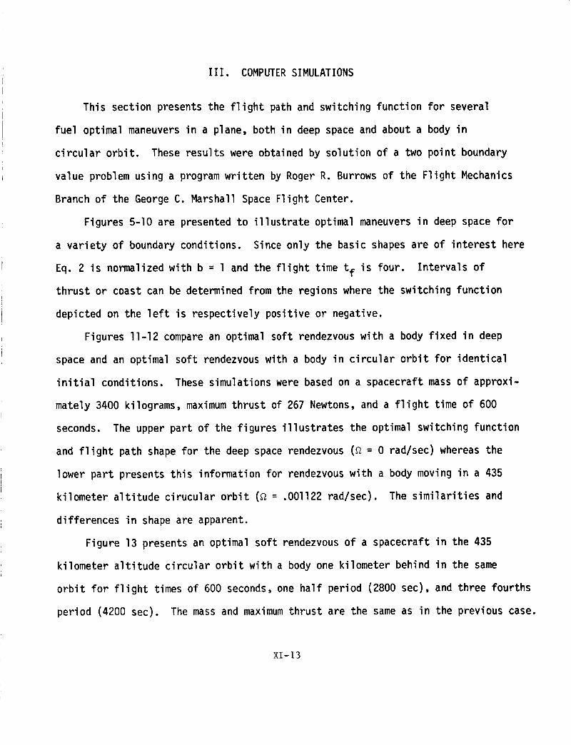
This section presents the flight path and switching function for several
fuel optimal maneuvers in a plane, both in deep space and about a body in
circular orbit. These results were obtained by solution of a two point boundary
value problem using a program written by Roger R. Burrows of the Flight Mechanics
Branch of the George C. Marshall Space Flight Center.
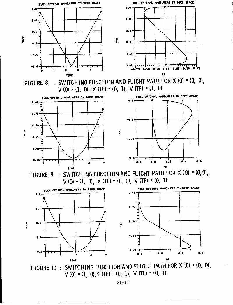
Figures 5-I0 are presented to illustrate optimal maneuvers in deep space for
a variety of boundary conditions. Since only the basic shapes are of interest here
Eq. 2 is normalized with b = l and the flight time tf is four. Intervals of
thrust or coast can be determined from the regions where the switching function
depicted on the left is respectively positive or negative.
Figures ll-12 compare an optimal soft rendezvous with a body fixed in deep
space and an optimal soft rendezvous with a body in circular orbit for identical
initial conditions. These simulations were based on a spacecraft mass of approxi-
mately 3400 kilograms, maximum thrust of 267 Newtons, and a flight time of 600
seconds. The upper part of the figures illustrates the optimal switching function
and flight path shape for the deep space rendezvous (_ = 0 rad/sec) whereas the
lower part presents this information for rendezvous with a body moving in a 435
kilometer altitude cirucular orbit (_ = .001122 rad/sec). The similarities and
differences in shape are apparent.
Figure 13 presents an optimal soft rendezvous of a spacecraft in the 435
kilometer altitude circular orbit with a body one kilometer behind in the same
orbit for flight times of 600 seconds, one half period (2800 sec), and three fourths
period (4200 sec). The mass and maximum thrust are the same as in the previous case.
XI-13

Figure 14 also presents a soft rendezvous in which the same spacecraft is
ferrying a mass nine times heavier than itself to a body in the 435 kilometer
circular orbit, The spacecraft begins one kilometer above the body with the
same velocity. The flight time is long, six sevenths of a period (4800 sec) and
the optimal thrusting function has four switches. The thrusting sequence is
"thrust-coast-thrust-coast-thrust."
Figure 15 depicts a situation in which the spacecraft pushes a mass nine
times heavier than itself out of circular orbit to a point in an elliptical orbit
73 kilometers behind. This optimal maneuver has a flight time of one period
(5600 sec) and the optimal switching function is determined from the curve q(t)
presented in Fig. 3. This can be seen from the similarity between Fig. 4 and the
switching function shown in Fig. 15. This is an example of an optimal maneuver
which has a thrusting sequence requiring the maximum of seven phases in one period.
XI-14

FIlL OPTIRdiL IMl',i£tJ_R$ XN DEEP SP_E
2,O-
O.S- _
\O,O"
-O.S-
-1 .O o
JJv
• 1 P. 3 4
FIGURE5 :
FU£L OPTI_L RFeNEAJUEI_ ZN KEP I_1
l.O-I_0.8-
.,11.4, .
0*2-
O.O"
|.O
i •
\
0.8 0.4 O.E
Tin( Xl
SWITCHINGFUNCTIONAND FLIGHTP_H FORX 10)- 10,V 10)=11, 0), X (TF)= 10, 1), V (TF)=10, O)
0),
8[-4N_ °
*O.n-
-O.SO-
-O."il_-
FU[L OPTIRAL tWIRUU[RS XN DEEP $PI4CE
O.U"_
\\
\
//
FUEL OPTIIqAL IW, I[IN(IIS ZN DEEP SPACE
FIGURE6 :
O.?S-
e.2S O.SO O.?S I.N
XlTZR[
SWITCHINGFUNCTIONANDFLIGHTPATHFORX (0) - (0,V (0) = (0, 0), X (TF)=(1, 1), V (TF)= (0, O)
0),
0.08-
O iS• °
0.04 -
O.Oa o
e.eo-
.
-O.O2-
.
-O.e4-
O
FUEL OPTZI_L R44NEUUERS ZN DEEP SPACE
1 a 3 4
TIRE
FUEL OPTIRAI. Iqi4NEUQ(IIIS IN DEEP SPACE
I,. LNJ-
|,N °
O.?S -
e.SO
e.2S-
• O O.|
e.eo °
jJ0.4
Xt
O.g
FIGURE 7 : SWITCHINGFUNCTIONANDFLIGHTPATHFORX (0) = (0, 0)V (0)=(I,0),X (TF)=(0,.I),V (TF)=(-I,O)
XI-15
FUEL OPTII_L RNIEU_RS IN DEEP SPACE
1.S-
,.._-'\
:\l.S--"
o.o-"
°0.$£
.
-t.o-"O 1
FIGURE 8 :
//
a 3
/
4 S
1.00-
TXlq(
IrLll[L OPTIMAl. HAH[UA.P[RS XN I)[P
0.$0-
1.0--
0.8-
0.6-
0*4-
0*2-
0*0-
f--
\\\
\
\
-0,?S-e.Se-O.ZS 0.00
Xl
J
0.2S 0.S0 0.71;
SWITCHING FUNCTIONAND FLIGHT PATHFORX (0) = (0,V (0) = (1, 0), X (TF)- (0, 1), V (TF) = (1, O)
FUEL OPTZIqAL RNIEUA.P[RS IN DEEP SPRCE
0.?S-
0.2S.
O*_"
\-0. L"J-
e 1
FIGURE 9 :
O0
/
0*4-
0.0"
FURL QPTIflAL R/4HEUUERS IH DEEP SPRCI
0.0-
.
-0.6-
E 3 4 -O,a 0.0 O.| 0.4
TIME XL
0),
-t) 2• °
e
o.4
SWITCHING FUNCTIONAND FLIGHT PATHFORX (0) -" (0, 0),
V (0)--(1, 0), X (TF): (0, 0), V (TF): (0, 1)FUEL OPTIMAL M_NELIQERS IN DEEP SP_CE FUEL OPTIRItL H_NELNERS IN DEEP SPI_C|
1 g 3
TIME
1 .O0-
e.?S-
e.se-
41.2S-
v
FIGURE 10 :
e.ee- , ' ,
0.e e.2 0.4 0.6
x!
SWITCHING FUNCTIONAND FLIGHT PATH FORX 10) : 10,
V (0):11,O),X(TF):10,1),V (TF): (0,11
0),
Xl-16

FUEL OPTIflRL RANEUUERS IN DEEP SPACE
e.ES--
BE-e6-
-Q.2S
-e.SO -
-O.?S-
*z .co J
e ilee 4oe
x
2
(M)
FUEL OPTIMAL RANEUUERS IN DEEP $P_CE
leee-
8ee-
Gee-
4ee
Eee-
Q--
//
//
see e aee 4ee see see ;eee
TXlq[ (SEC) XI (M|
FUEL OPTIRRL RANUEUERS kbUUT R CIRCULAR ORIZT
e 2
0*0-
-e.a
-0.4
-e.ll-
-e.8-
FUEL OPTIMRL MRNUEUERS MBUUT R CIRCULMR ORE|T
X
2
(M)
leo_ --
800
6OO
40_ -
20e - f
//
J! ii
i_ee 4ee see e 2;);) 4ee Gee Bee leee
T! nE(SEC) x l (M)
FIGURE11 : COMPARISONOFSWITCHINGFUNCTIONSANDFLIGHTPATHSFORDEEPSPACEAND435 KM. ALTITUDECIRCULARORBIT:X (0) = (1000, 1000),V (0) = (0, 0), X (TF)= (0, 0), V (TF)= (0, O)
Xl-17

FUEL OPTIRRL flANEUUERS IN DEEP SP_¢E FuEL OPTIMAL MANEUUERS IN DEEP SPACE
O.?S
e.se-
_.ES-
e.ee
-e.as-
-e.se-
-o.?s-,
\
!
4ee
! " !
e eee 6ee
TIME (SEC)
x
(M)
leee -
?$e -
see
2se -
e
/)
-2se-
-2ee e 2co 40e Bee
!
Gee
XZ(M)
FU(L OPTIMAL MRNU(UERS RDOUT R CIRCULAR OR)I?
6.Se-
;).25-
6E-e6
-e.2S-
-O.S;) o
-e.75 !
;ee
x
(M)
FUEL OPTIMAL IqRHUEUERS RgOUT A CIRCULAR OR|IT
3-1o----o5-1leee --(,
-,.,--,..
?Se -
50e -
;_SO -
-2SG - ! !
TIME (SEC) XI(M)
FIGURE 12 : COMPARISON OF SWITCHING FUNCTIONS AND FLIGHT PATHS
FOR DEEP SPACE AND 435 KM. ALTITUDE CIRCULAR ORBIT:
X (0)= (0,1000),V (0)=(10,0),X (TF)= (0,0),V (TF)=(0,O)
X1-18

FUEL OPTZfl_L MANUEUER$ RE_T R CIRCULAR OR|IT
O.2-
-O.2--e.4-
-O.l;-
-0.8-
1) 2OO 4OO 6cO
TIP,[(SEC)
Xa
(M)
°
-50 -
.
-lee-
-ISe-
FUEL OPTZNAL FIANUEUERS ABOUT A CIRCULAR CRIlZT
//
/11 25t) See ?Se Iee1)
FUEL OPTIMAL NRNUEUERS _bOUT R CIRCULAR ORBIT
e.a
E -1) 6 .._
-e.;_
*e.4
-1).6-
-e.9-
-! .1)-
e
b
\\
v
i I I 1 1 v I !
1)ee
L%
/
//
FUEL
1).-(
-leO"
X:s,
(M)
-3ee
)PTIN*L PI_MUEVERS _IIOuT A CIRCUL*q Ol]
I l I I
a1)1)1) 3o1)o e aee 4t_e
TIME ($EC) Xl I_,_1
FUEL 0PT][RnL I_RNUEUERS ABOUT A ¢IRCULMR 0RIIT
1).;!--
0+0-
-1).a
-e.4
-;).6 -
-1).8
\ / f
FIGURE13 :
FUEL OPTIr_nL m_'_VE_.'E;_S A)OU'r a C:_C-'_.ao )=.e:-
-50 -
-100-
X2
(M) - ++o
-200 -
/
-aSO" , , , • , , , •
lee9 ae1)e 31)ee 4eee 51)e1) -aSo (_ _.=+ .=(_e ":.ce 1_o," : _'_ ,"
T I elE (SEC) × 1 (',_)
SWITCHINGFUNCTIONANDFLIGHTPATHFORDIFFERENTFLIGHTTIMES FOR435 KM. CIRCULARORBIT:X(0) =(1000, O)V (0) = (0, 0), X (TF)= (0, 0), V (TF)= (0, O)
XI-19

FJ_L nPTIMAL RAHUEUERS ABOUT A CIRCULAR ORBIT FUEL OPTIMAL MANUEUER$ ABOUT A CIRCULAR ORBIT
Qo4--
O.a--
Q.Q-
-e.a -
-I,4" I I I i
g tee+ aeoe
xa
(M)
15e0-
leee-
see - \
-see-
-see e 5eg lees 1see 25e$
TIRE (SEC) X! (M)
FIGURE 14 : INSERTION OFMASS FROMELLIPTICAL INTO 435 KM.
CIRCULAR ORBIT:X (0)=(0, I000), V(O)=(0, 0),X (TF) = (0, 0), V (TF) = (0, 0),OPTIMAL MANEUVERREQUIRESMID-COURSE THRUST
FUEL OPTIRAL RAHUEUERS ABOUT A CIRCULAR ORBIT FUEL OPTIRAL RANUEUERS ABOUT A CIRCULAR ORBIT
$.?S- I --
II.511
$.25
$.gg -
-e.25-
e 51
xE
(M)
X16 4
Q-
-t
-2-
/
/! -3-
e £eee -8 -6 -4 -2 e a
x% (M) Xle 4
FIGURE 15 : AN OPTIMAL MANEUVER WITH FOURTHRUSTSAND THREE
COASTS IN ONE PERIOD (5600 SEC):X (0) = (0, 0), V (0) -- (0, O)X (TF) = (-73000, 0), V (TF) = (0, 35)
Xl-20
IV. CONCLUSIONS
Several different forms of solutions to Eq. lO can occur. If _ = 0 the
solution is a line segment and the optimal control consists of intervals of full
thrust and coast with at most two switches. If _ # 0 the solution may be a
helical type segment, a shifted sine curve segment, a horizontal straight line
segment, a prolate or curtate cycloidal type segment, or a segment of an ellipse.
The optimal control consists of intervals of full thrust and coast in each of
these cases. More than two switches are possible even for small flight times.
If cI # 0 there is a maximum of six switches possible in one period. If cI = 0
the maximum number of switches that can occur in one period is four.
If _ # 0 only two cases exist in which singular solutions (defined by Eq. 20)
can occur outside of the orbital plane. Also only two cases where singular
solutions (defined by Eq. 21) exist can occur on the orbital plane.
Computer simulations were run for solution of Eqs. 2, 3, 6, and 7 for cases
where _ = 0 and where _ = 2_/5600 rad/sec. It was found generally that for small
flight times and boundary conditions of small magnitudes the optimal maneuvers
contained no more than two switches. Boundary value problems whose solutions
consisted of four switches and six switches were found.
XI-21
REFERENCES
I. I. Flugge-Lotz and H. Marbach, "The Optimal Control of Some Attitude
Control Systems for Different Performance Criteria," Trans. ASME J.
Appl. Mech. (1964) pp. I07-I15.
2. J. S. Meditch, "On Minimal Fuel Satellite Attitude Controls," Preprintsof the 1963 JACC.
3. L. Schwartz, "Minimum Energy Attitude Control for a Class of Electric
Propulsion Devices," Proceedings, 1964 JACC.
4. D. A. Conrad, "Minimum Fuel Closed-Loop Translation," AIAA J. (May 1965).
5. W. F. Keller, "Study of Spacecraft Hover and Translation Modes Above the
Lunar Surface," AIAA Preprint 64-341.
6. H. O. Ladd and R. Friedland, "Minimum Fuel Control of a Second Order Linear
Process With a Constraint on Time-to-Run," Trans. ASME J. Appl. Mech. (1964)
pp. 165-176.
7. D. R. Snow, "Singular Optimal Controls For a Class of Minimum Effort Problems,"
SIAM J. Control, (1964) pp. 203-219.
8. M. Athans, "Minimum-Fuel Control of Second-Order Systems With Real Poles,"
1963 JACC, pp. 232-240.
9. A. J. Craig and I. Flugge-Lotz, "Investigation of Optimal Control With
Minimum-Fuel Consumption Criteria for a Fourth-Order Plant With Two Control
Inputs: Synthesis of an Efficient Sub-Optimal Control," 1963 JACC.
lO. M. Athans, "On Optimal Control of Self Adjoint Systems," 1963 JACC.
II. W. C. Grimmell, "The Existence of Piecewise Continuous Fuel Optimal Controls,"
SIAM J. Control (1967), pp. 515-519.
12. D. L. Grey and M. Athans, "Computation of Fuel-Optimal Control via Newton's
Method - Theory," 1968 JACC.
13. T. E. Carter, "Fuel Optimal Maneuvers for Spacecraft with Fixed Thrusters,"NASA CR -161855 (1981).
14. E. B. Lee and L. Markus, Foundations of Optimal Control Theory, Wiley, 1967.
XI-22