Embed Size (px)
Citation preview
NASA TECHNICAL MEMORANDUM ) NASA TM-88388
PERFORMANCE OF THE HIGH SPEED ANECHOIC WIND TUNNELAT LYON UNIVERSITY
M. Sunyach, B. Bruiel , G. Comte-Bellot
(NASA-TM-88388) PERFORMANCE OF THE HIGH N86-28965SPEED ANECHOIC W I N D T U N N E L AT LYONU N I V E R S I T Y {National: Aeronautics and SpaceAdministration) 23 p CSC1 14B Unclas
G3/09 43460
Translation of "Performances de la soufflerie anechoique agrandes vitesses de 1'ecole centrale de Lyon", Revue d'Acoustique, vol. 18, no. 73, 15 pages, 1985.
NATIONAL AERONAUTICS AND SPACE ADMINISTRATIONWASHINGTON D.C. 20546 MARCH 1986
https://ntrs.nasa.gov/search.jsp?R=19860019493 2018-06-19T04:42:10+00:00Z
ITAW&ARO
1. Rveoil N*.NASA TM-88388
8. I A<«eo«!oo MID, ]. 'o Co»«l»g He.
4. Till. V.b«tl«
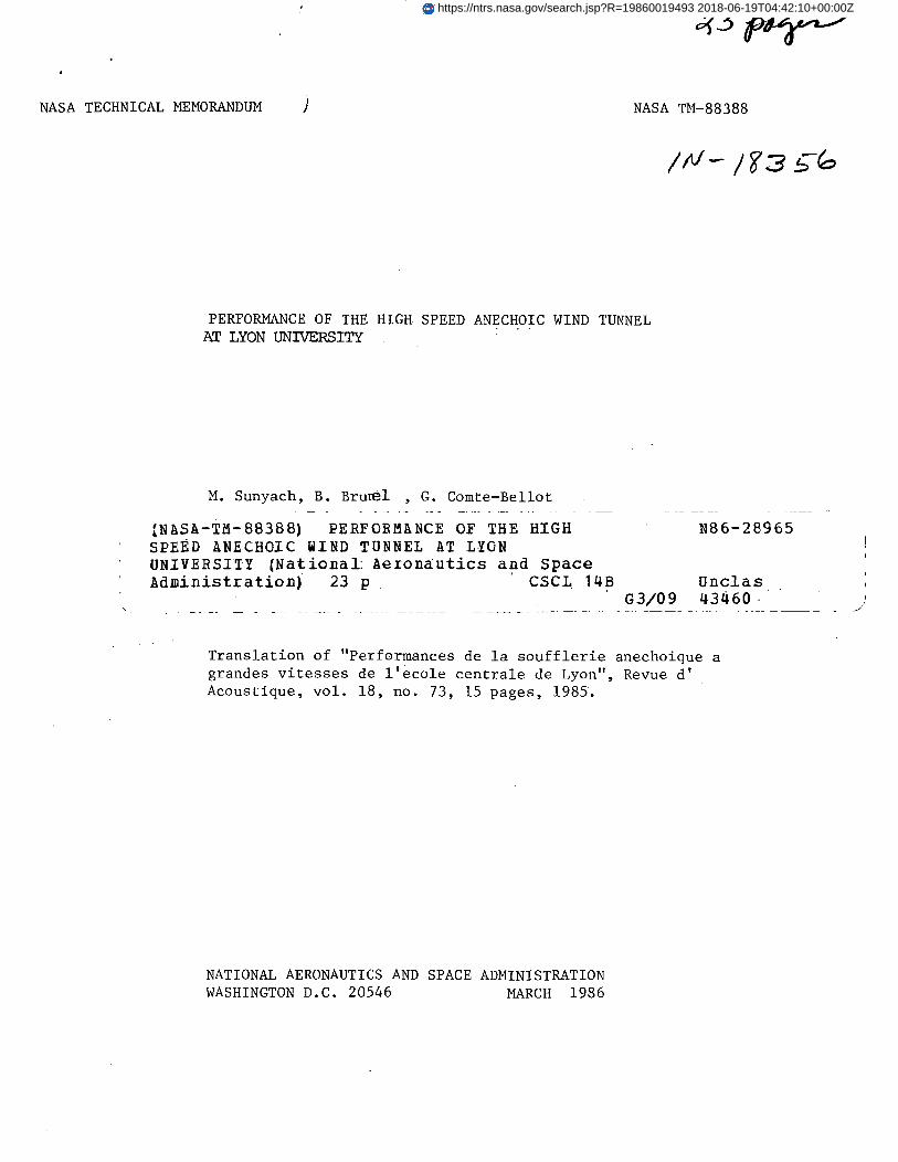
PERFORMANCE OF THE HIGH SPEED ANECHOIC WINDTUNNEL OF THE "ECOLE CENTRALE DE LYON"
MARCH, 1986
7. Org«n)io>len Rapafi Mo.
M. Sunyach, B.Brunei, . G. Comte-Bellot 10. Wo/h Unit H..
9. P informing 0'(cnil«li*H Homo »*4 AJ^'«»
SCITRANBox 5456
Barbara . CA 9"U fifl
11. Centred or C'enlNASw- '4004
13. Tyfo •( Rop»'l Mi4
TranslatioaU.
National Aeronautics and Space Administrationa, D.C. *0546 IS. C»4o
19. H»»»»
Translation of "Performances de la soufflerie anechoique a grandes vitessesde 1'ecole centrale de Lyon", Revue d' Acoustique, vol. 18, no. 73, 15 pages,1985. (A85-44049)
16.
The characteristics of the feed duct, the wind tunnel and the: experiments run in the convergent-divergent anechoic wind tunnel at Lyon >.University are described. The wind tunnel was designed to eliminatenoise from the entrance of air or from flow interactions with thetunnel walls so that noise caused by the flow-test structure interactionscan be studied. The channel contains 1 x 1 x 0.2 m glass and metal foilbaffles spaced 0.2 m apart. The flow is forced by a 350 kW fan in theprimary cirucit, and a 110 kW blower in the secondary circuit.'Theprimary circuit features a factor of four throat reductions, followed bya 1.6 reduction before the test section. Upstream and downstream sensorspermit monitoring of the anechoic effectiveness of the channel. Othersensors allow modeling of the flow structures in the tunnel. The tunnelhas been used to examine turbulent boundary layers in flows up to 140 m/sec., turbulence-excited vibrations in walls, and the effects of laminar andturbulent, flows on the appearance and locations of noise sources.
l@. CXeeriimMoa Stet*
Unclassified and Unlimited
CI««tU. (,(
Uncl&eeifie4 23IS. Prim
"\
PERFORMANCE OF THE HIGH SPEED ANECHOIC WIND TUNNEL ar LYON UNIVERSITY
By M. Sunyach, B. Brunnel, G. Comte-Bellot*
Abstract
This continually adjustable anechoic wind tunnel gives the following/316*
maximum speeds:
160 m/s in a cross section of 0.4 m x 0.2 m
80 m/s in a cross section of 0.6 m x 0.4 m
35 m/s in a cross section of 1.4 m x 0.6 m
It has several specific technical characteristics:
1 The motor portion is on the upstream side which enables direct evacuation
of the flow from the chamber thanks to a wall composed of an adjustable
opening and movable baffles.
2 The jet feed system is of the bypass type which reduces the noise
specific to the primary airflow at high speeds.
3 An associated system of lateral manifolds and passages with baffles
controls the flow of the jets thus immensely reducing secondary flows which ,
exist in the anechoic chamber. j
The presentation points out the various aerodynamic and acoustic
properties of the system, in particular acoustic insulation of the
*TSfumt»ers in margin indicate foreign pagination.
facility, the map of secondary flows, the chamber cutoff frequency, and the
noise itself.
Some examples illustrating the research presently conducted on this
test facility are then presented.
I. INTRODUCTION
Analysis of flow noise generation and radiation of structures excited
by flows is greatly facilitated if one has available a test facility
combining both a silent air input and an anechoic chamber.
There exist some set-ups of this type, in particular at the David
Taylor Naval Ship Research and Development Center (Bethesda, USA), in
several NASA laboratories (Ames, Langley, and Lewis, USA), at the National
Gas Turbine Establishment (Farnborough, GB), at Dassault-Brequet (Velizy,
France), and at the Ecole Centrale de Lyon. More recently, two more modern
facilities were constructed:
317
the CEPRA-19 wind tunnel in Saclay and the Dutch-German (DNW) wind tunnel
in the North Polder near Amsterdam. The operating principles employed vary
from one facility to another: set-up in a closed system [1, 2, 3], use of
an output manifold with an evacuation system [4], placing of the high
pressure section on the upstream side [5],
This last principle was chosen for construction of the new test
facility built at the ECL. It has several advantages:
. Possibility of having a large anechoic chamber free of any obstacles such
as pick-up manifolds;
. Good acoustic and aerodynamic control of the airflow arriving in the
chamber;
. Direct elimination of the flow after traveling through the chamber;
. Possibility of setting up several coaxial or adjacent jets in order to
reduce the noise level of the primary jet such as in aeronautical bypass
systems;
. Possibility of combining lateral air inputs in order to supply the jets
with drawn air and to thereby reduce the recirculation flows which would
exist in the confined space.
This report presents the properties of the chamber, the wind tunnel,
and some examples of use of the test facility.
II. DESCRIPTION OF THE FACILITY
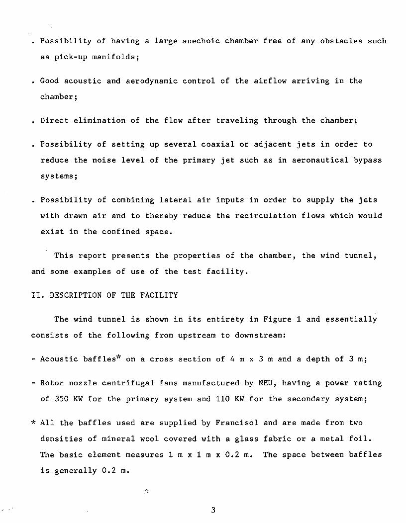
The wind tunnel is shown in its entirety in Figure 1 and essentially
consists of the following from upstream to downstream:
- Acoustic baffles* on a cross section of 4 m x 3 m and a depth of 3 m;
- Rotor nozzle centrifugal fans manufactured by NEU, having a power rating
of 350 KW for the primary system and 110 KW for the secondary system;
- All the baffles used are supplied by Francisol and are made from two
densities of mineral wool covered with a glass fabric or a metal foil.
The basic element measures 1 m x 1 m x 0.2 m. The space between baffles
is generally 0.2 m.
ORIGINAL PAGE ISOF POOR QUALITY 318
Figure 1
Sketch of new high-speed anechoic wind tunnel at the Ecole Centrale de
Lyon
- Acoustic baffles placed in the ducts over a 5-meter length for the
primary system and a 4-meter length for the secondary system;
- The subdivision system of the secondary airflow on either side of the
primary system;
- Grids and honeycomb structures;
- An initial reduction with a ratio of 4 for the primary airflow as well as
the secondary airflows;
- A second reduction at the input of the flows into the chamber with a
ratio of 1.6 for the primary system and 1.4 for the secondary system;
- Jet nozzles with a reduction of 3.9 for the primary jet (with an output
cross-section of 0.4 m x 0.2 m) and a reduction of 2.8 for the two
secondary jets combined (with an output cross-section of 2 x 0.4 m x 0.2
m).
319
The anechoic chamber with its slightly diverging walls has the
following average effective dimensions: 10.3 m, 8 m, and 7.6 m. It is
semi-buried except for the face opposite the jet input which is made up of
3 rows of 26 vertical baffles (thickness 0.2 meters; total depth 3 meters)
on a cross-section of 8.15 m x 8.4 m. The air can pass between the baffles
and, what's more, the middle row of baffles is set on a sliding mount in
order to free a central opening of 3.20 m x 2.20 m which is used for direct
evacuation of the jet to the outside. The five other faces are covered on
the inside with fiberglass in panels 40 mm thick and 450 mm, 675mm, and -850
mm long, and a density of 37 kg/m3 and 70 kg/m3 combined with a base mesh
measuring 0.60 m x 0.60 m.
Two open lateral channels on the exterior (cross-section of 2 m x 1.5
m) are arranged on either side of the chamber and communicate with acoustic
baffles surrounding the airflows right at their input into the anechoic
chamber on a cross-section of 3 m x 3.50 m and a depth of 2 m. These
channels supply the jets with drawn air (cf. chapter VI).
A grating which can be moved over its largest portion provides for
communication with the chamber. It can reach the outside so that machines
to be tested in the chamber can be brought in. Support bars and attachment
points are used to mount the various pieces of measuring equipment which
must be put in the chamber.
III. ANECHOIC PROPERTIES OF THE CHAMBER
The anechoic nature of the chamber was analyzed by measuring the
decrease in the sound pressure from a near tnonopolar source (loud speaker,
Focal 5N 81 dB, diameter 13 cm, in a small closed box) with emissions in
the 40 Hz to 4 kHz frequency range. Two Neutrik electret microphones of
the 3281 type are used, one stationary 1 meter to the downstream side of
the source and the other movable. Two decrease directions were explored in
the horizontal median plane of the chamber: the longitudinal direction
toward the baffles and the crosswise direction toward the lateral walls.
In an initial phase an impulse emitted by the loud speaker is
digitally recorded (transiscope DIFA TR 1030, 1 MHz sampling) so that the
microphone emitting distance can be determined. Next, a wide band
measurement is made using a two-channel FFT analyzer type HP 3582 A. The
results are then processed by a POP 11-03 minicomputer in order to give the
results in thirds of an octave and automatic plotting of the decreasing
curves.
8.888
-2.888 _
-6.880 _
-8.880 _
-18.800 _
-12.880 _
/ FREQUENCE CENTRALE < 783
ORIGINAL PAGEOF POOR QUALITY
320
4. 5.DISTANCE Con *>
W
n
8.388
-2.888
-4.888
-€.888
-8.888
-10.
-12.
FREQUENCE CENTRALE t 78
4. 5.DISTANCE <•* m>
3
1 »>
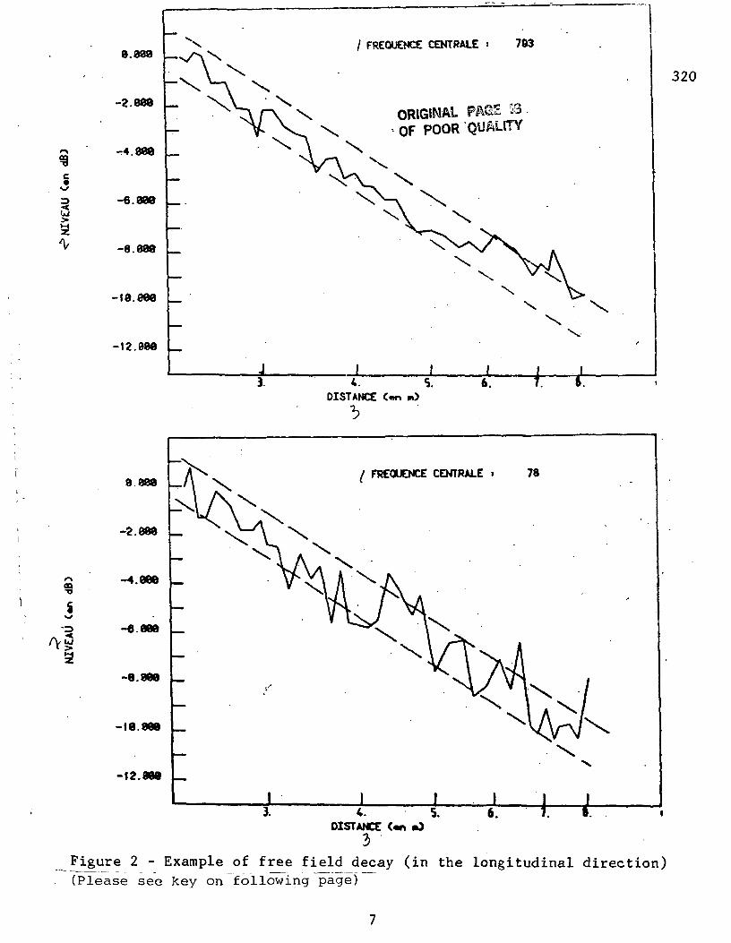
Figure 2 - Example of free field decay (in the longitudinal direction)(Please see key on following page)
Key to Figure 2
1: Central frequency 2: Level (in dB) 3: Distance (in meters)
321
The results obtained for the longitudinal direction and for two
typical frequencies N = 78 Hz and 783 Hz, are presented in Figure 2 with
indication of the theoretical decrease in 1/r and a bandwidth precision of ±
1 dB. In spite of a slight reflection which occurs on the baffles at low
frequencies, the anechoic nature of the chamber is good for N approximately
greater than 75 Hz, even in the direction in which the acoustic response of
the baffles was not known previously.
V. AERODYNAMIC CHARACTERISTICS OF THE OUTPUT AIRFLOWS
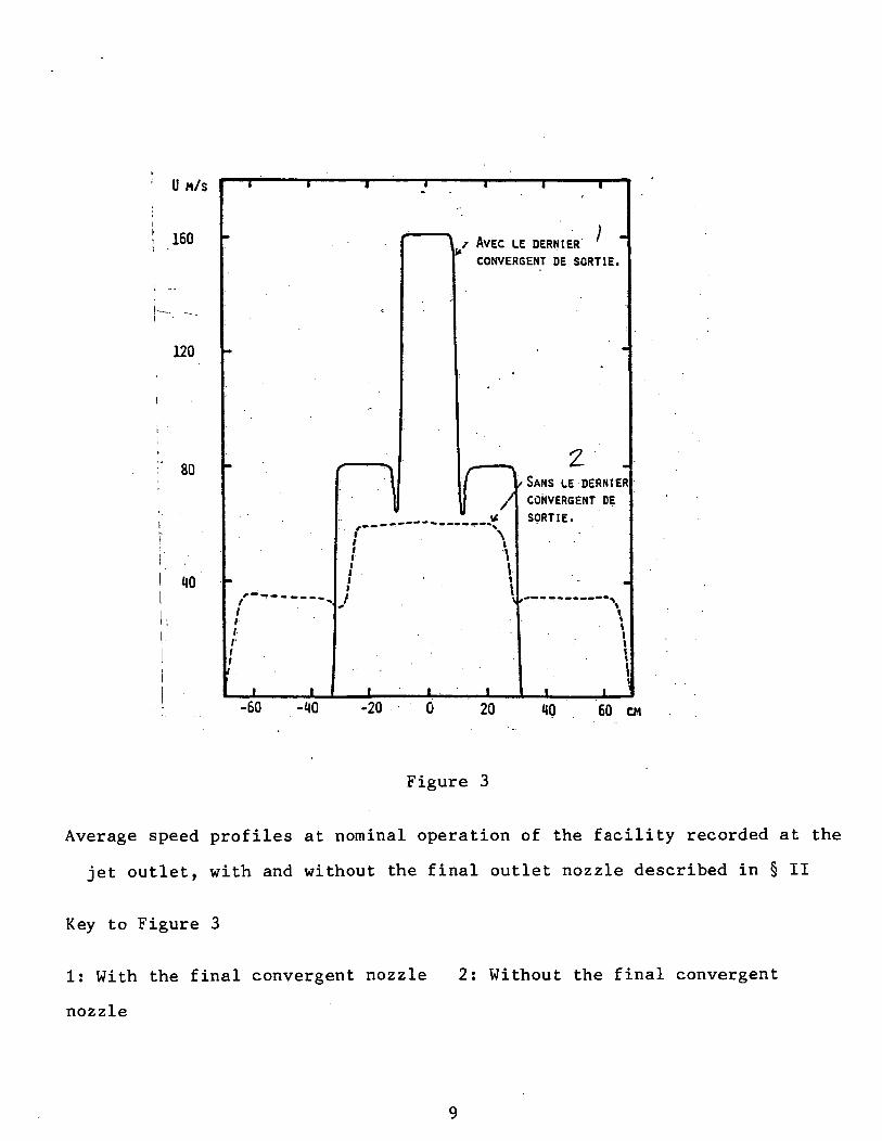
The average speed profiles were determined at the output of the jets
at a point level with the covering for the large section of the airflow and
1 meter from this point when the nozzles mentioned in § II are in place.
The results obtained are given in Figure 3 and show that by acting on the
speeds of the primary jet and the secondary jet respectively we can obtain:
8
1 U M/S
\ 160
120
80
! 1)0
r•ii/
/ AVEC LE DERNIER
CONVERGENT DE SORTIE.
-60 -40 -20
SANS LE DERNIER
CONVERGENT DE
SORTIE.
20 60 CM
Figure 3
Average speed profiles at nominal operation of the facility recorded at the
jet outlet, with and without the final outlet nozzle described in § II
Key to Figure 3
1: With the final convergent nozzle 2: Without the final convergent
nozzle
322
160 m/s for a cross-section of 0.40 m x 0.20 m with two adjacent flows of
half that speed
80 m/s for a cross-section of 0.60 m x 0.40 m.
35 m/s for a cross-section of 1.40 m x 0.60 m.
> -The ratio X • us/
up of the secondary speed to the primary speed (
= 0.5 at nominal operation) as well as the ratio B1 of the secondary
section to the primary section (in this case set at B1 = 2) are defined by
searching for an acoustic optimum of a bypass system, cf. [6, and 7] and §
VII.
The preturbulence level of the flows is 0.2% at the outlets of the
jets and 0.4% at the input of the airflows in the chamber. The
measurements were made according to the traditional method with a hot wire
anemometer: a ten-micron tungsten wire, 0.8 overheat, DISA 55 D01 constant
temperature anemometer.
The potential lengthening of the cone of the primary jet under the
effect of the secondary adjacent jets is being studied. The first tests
indicate that even without the lateral jet guide baffles it is about 30%.
V. ACOUSTIC DAMPING OF THE DUCT SILENCERS
The acoustic damping which may be provided by the duct silencers was
studied by placing a noise source in the machinery room and by measuring
the remaining sound levels on the downstream side in the anechoic chamber
at the center of the primary jet nozzle. The measurements are made by
thirds of an octave using a BK 4145 1" microphone and a BK 4417 analyzer.
10
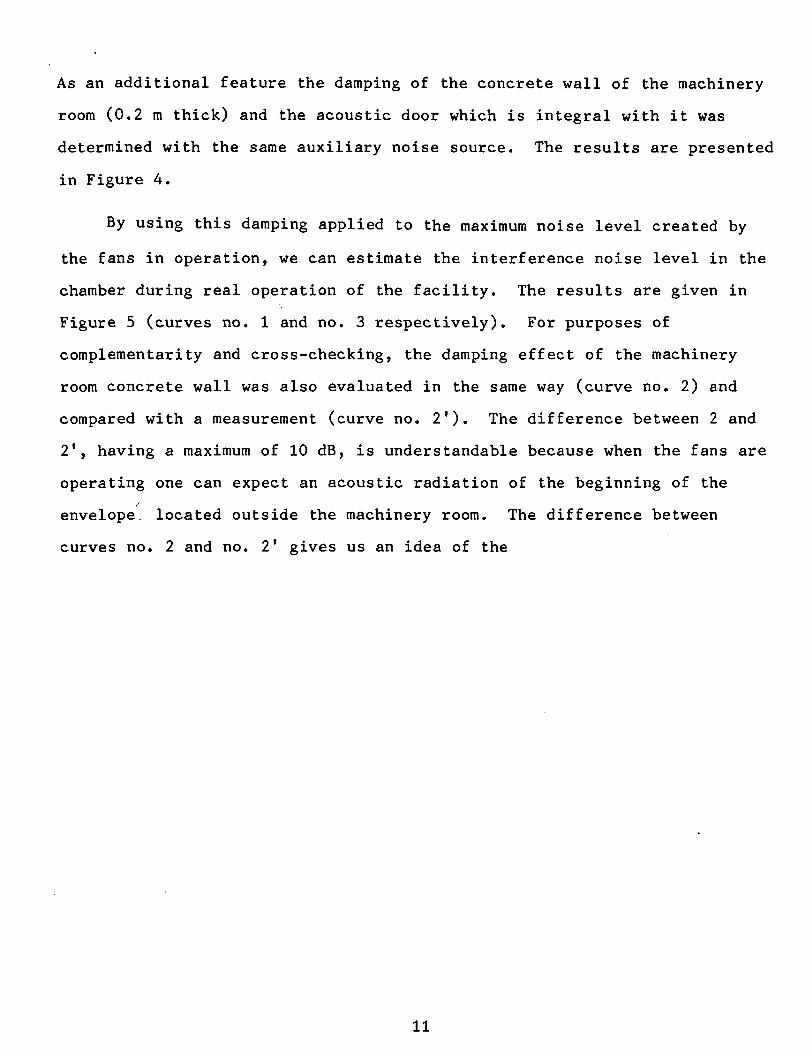
As an additional feature the damping of the concrete wall of the machinery
room (0.2 m thick) and the acoustic door which is integral with it was
determined with the same auxiliary noise source. The results are presented
in Figure 4.
By using this damping applied to the maximum noise level created by
the fans in operation, we can estimate the interference noise level in the
chamber during real operation of the facility. The results are given in
Figure 5 (curves no. 1 and no. 3 respectively). For purposes of
complementarity and cross-checking, the damping effect of the machinery
room concrete wall was also evaluated in the same way (curve no. 2) and
compared with a measurement (curve no. 21). The difference between 2 and
2', having a maximum of 10 dB, is understandable because when the fans are
operating one can expect an acoustic radiation of the beginning of the/
envelope, located outside the machinery room. The difference between
curves no. 2 and no. 2* gives us an idea of the
11
ORIGINAL :PA6E ISOF POOR QUALITY
dB
70
50
50
10
LOCAL VENTILATEURS \
HALL DES CONDUITS /-
A LA BUSE PRIMAIRE /
BRUIT DE FOND U
0,1 0>16 0.25 0,<» 0,63 1 1,6 2,5 "« 6,3 KHZ
Figure 4
Acoustic Transmission loss of in-duct silencers
Measurement with an acoustic source located in the machinery room
Key to Figure 4
1: machinery room 2: duct chamber 3: at the primary nozzle 4:
background noise
323
12
ORIGINAL PASE ISOF POOR QUALITY
dB
90
70
50
30
MM
...
••
MM1
^ ™
MM
•~*
...
—^ ™
mm*
\
}
^m
....
...
.... ...
...
i
.
—
—
• • •
^~
nr.
i
M iM
• •*«
• •«
iMM
1^
I MH>
"".
...
• •1
••i
•• •M
__
• • • 1
MM*
••i
...
—
•M
Lo
HA
HA
A
0,1 0,16 0,2S 0,<» 0,63 1 1,6 2,5 t 6,5 KHZ
LOCAL VENTILATEURS (1) \
HALL DES CONDUITS (2)(HESURES)
HALL DES CONDUITS (2')(ESTIMATIONS)
A LA BUSE PRIMAIRE (3)(ESTIMATIONS)
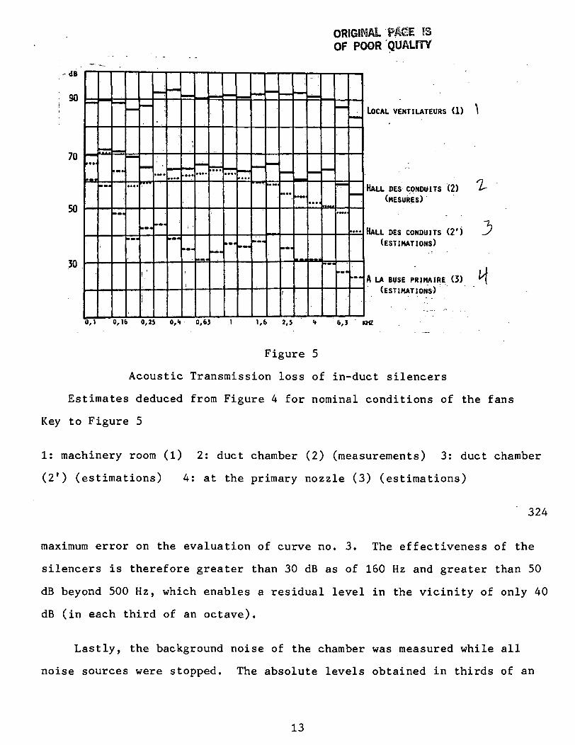
Figure 5
Acoustic Transmission loss of in-duct silencers
Estimates deduced from Figure 4 for nominal conditions of the fans
Key to Figure 5
1: machinery room (1) 2: duct chamber (2) (measurements) 3: duct chamber
(21) (estimations) 4: at the primary nozzle (3) (estimations)
324
maximum error on the evaluation of curve no. 3. The effectiveness of the
silencers is therefore greater than 30 dB as of 160 Hz and greater than 50
dB beyond 500 Hz, which enables a residual level in the vicinity of only 40
dB (in each third of an octave).
Lastly, the background noise of the chamber was measured while all
noise sources were stopped. The absolute levels obtained in thirds of an
13
octave are also indicated in Figure 4.
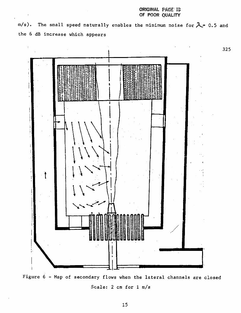
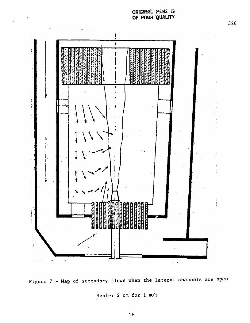
VI. SECONDARY FLOW MAPS IN THE CHAMBER
The secondary flows were measured in the median horizontal plane of
the chamber using an Anemotherm probe equipped with a clinometer with the
wind tunnel operating at its nominal speed (primary airflow at 160 m/s,
secondary airflow at 80 m/s). Two configurations were compared: one with
the lateral manifolds closed (Figure 6) and one with the lateral manifolds
open (Figure 7) in which case a speed of 2.80 m/s is produced. One can
clearly see that when the supply of the jets is allowed through the
acoustic baffles surrounding the nozzles, a reduction by a factor of about
2 occurs at nearly all the points explored. The flows do not exceed 1 m/s
in the entire useful zone for the acoustic measurements (some checks in the
median vertical plane of the chamber are presently being made). It can
also be observed that in a relatively large zone the speeds are even lower
(approximately less than 0.20 m/s) enabling fairly simple use of acoustic
probes of the interferometry type and vector acoustic intensitometers.
VII. ACOUSTIC EFFECTIVENESS OF THE BYPASS SYSTEM
The acoustic gain of the bypass system was checked by overall level
measurements and spectrum measurements. In these tests the microphone
(1/2" BK 4133) was placed in the vertical plane of symmetry of the jets 1.5
m above the horizontal median plane and 1 m downstream of the jet outlet
plane. The spectrums were obtained with a Hewlett Packard 3582 A analyzer.
In the first series of tests the noise level of just the primary jet,
Jl, and the noise level of both the primary jet and the secondary jets, J^
+ J2 were measured for various speeds of the secondary jet. The results
are indicated in Figure 8 for two values of the primary speed (160 and 80
14
ORIGINAL R40£ ISOF POOR QUALITY
m/s). The small speed naturally enables the minimum noise f or
the 6 dB increase which appears
.= 0.5 and
325
Figure 6 - Map of secondary flows when the lateral channels are closed
Scale: 2 cm for 1 m/s
15
ORIGINAL PASE ISOF POOR QUALITY
326
Figure 7 - Map of secondary flows when the lateral channels are open
Scale: 2 cm for 1 m/s
16
327
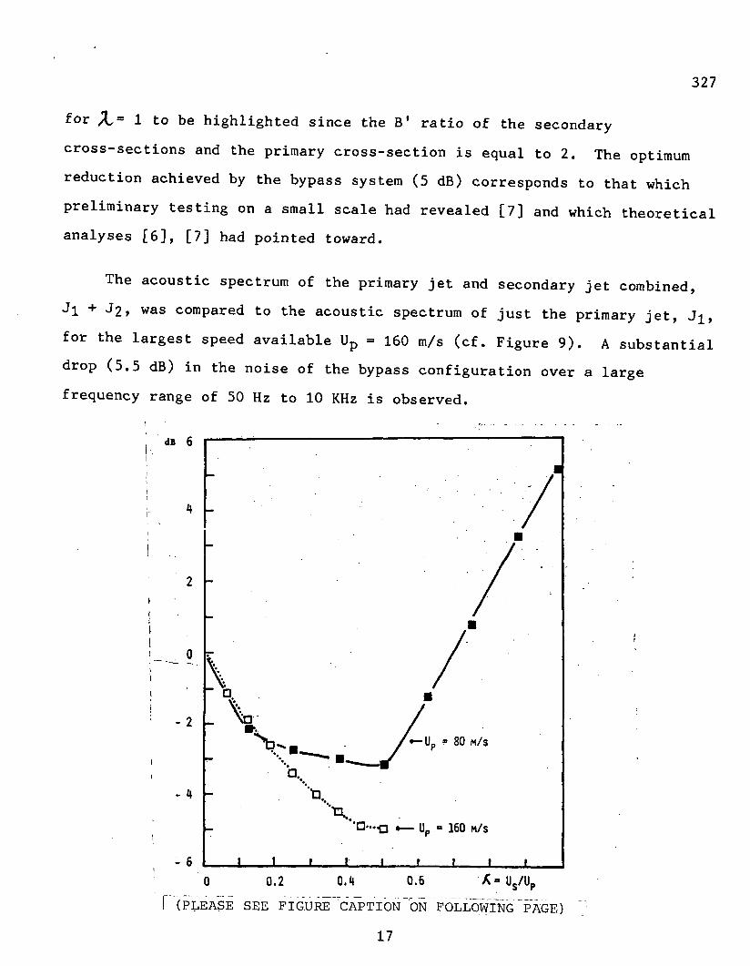
for X- 1 to be highlighted since the B1 ratio of the secondary
cross-sections and the primary cross-section is equal to 2. The optimum
reduction achieved by the bypass system (5 dB) corresponds to that which
preliminary testing on a small scale had revealed [7] and which theoretical
analyses [6], [7] had pointed toward.
The acoustic spectrum of the primary jet and secondary jet combined,
Jl + J2> was compared to the acoustic spectrum of just the primary jet, Jj,
for the largest speed available Up = 160 m/s (cf. Figure 9). A substantial
drop (5.5 dB) in the noise of the bypass configuration over a large
frequency range of 50 Hz to 10 KHz is observed.
dB 6
- 2
- 6
V'b.
r«-l) = 80 M/S
160 M/S
0.2 0.4 0.6 Us/Up
T (PLEASE SEE _ FIGURE CAPTION ON FOLLOWING ' PAGE)
17
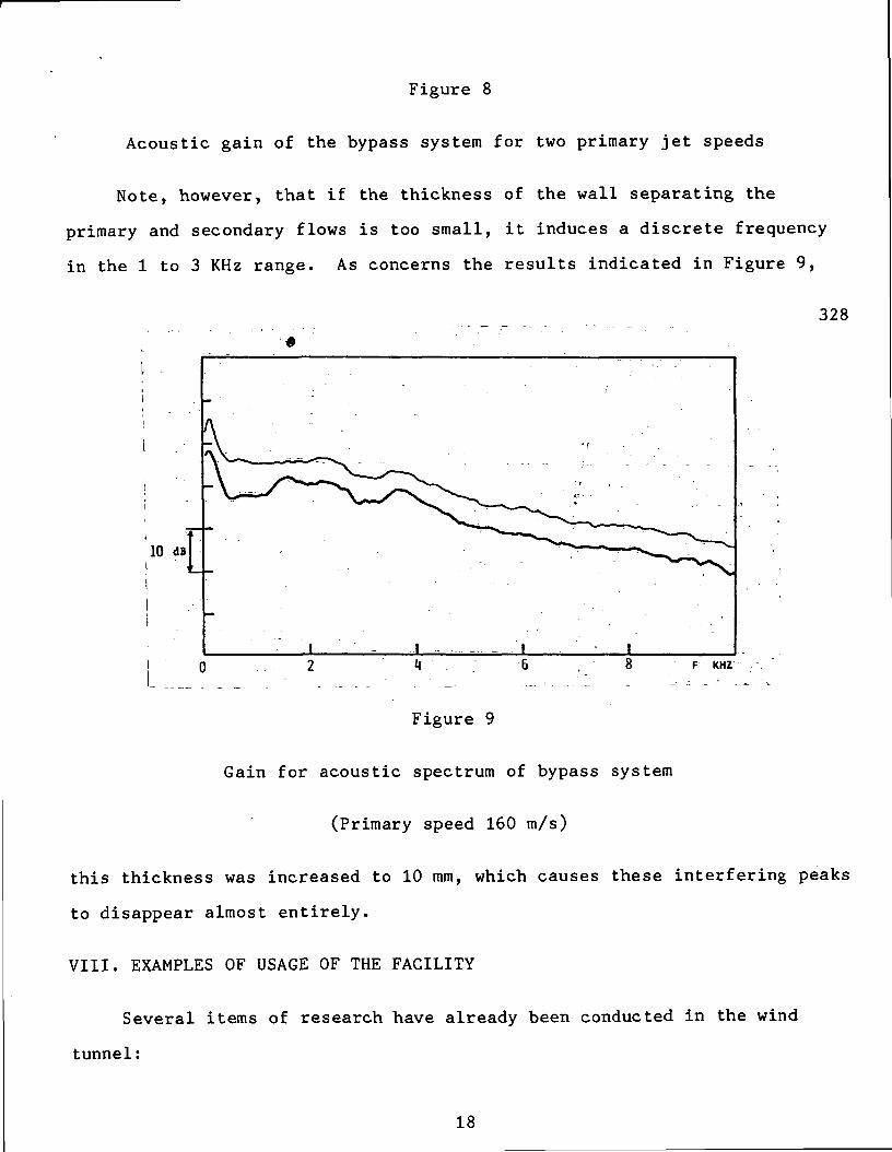
Figure 8
Acoustic gain of the bypass system for two primary jet speeds
Note, however, that if the thickness of the wall separating the
primary and secondary flows is too small, it induces a discrete frequency
in the 1 to 3 KHz range. As concerns the results indicated in Figure 9,
328
10 dB
F KHZ
Figure 9
Gain for acoustic spectrum of bypass system
(Primary speed 160 m/s)
this thickness was increased to 10 mm, which causes these interfering peaks
to disappear almost entirely.
VIII. EXAMPLES OF USAGE OF THE FACILITY
Several items of research have already been conducted in the wind
tunnel:
18
- Study of the parietal pressure fields under the turbulent boundary layers
up to 140 m/s. In particular, the very low level of the interfering
signals (upstream noise, wall vibrations) was a very interesting property
of the facility [8] (in cooperation with Metraflu);
- Study of the vibro-acoustic response of walls excited by turbulent
boundary layers and analysis of the phenomena of coincidence between the
aerodynamic convection speed of the exciting field and the speed of the
deflection waves in the plate [8] (in cooperation with Metraflu);
- Study of the effect of a laminar or turbulent boundary layer on the
localization of noise sources using an interferometry probe [9] (in
cooperation with Metraflu);
- Effect of a high speed flow on an ultrasound thermometer which is to be
airborne on an aircraft (in connection with the University of Paris VI).
329
Other research projects are presently in progress: analysis of
disturbances to acoustic wave propagation caused by thermal turbulence;
measurement of turbulent pressure fields in three-dimensional and detached
zones.
As we near the completion of one year's usage, it appears that the
facility is flexible and likely to accommodate various types of test
configurations.
ACKNOWLEDGEMENTS
We are very grateful to the personnel of the fluid mechanics
laboratory design office of the ECL, and especially to Mr. J.C. Robert and
19
Mr. P. Dutheil for their substantial help in drawing up the plans of the
facility and their follow through on items manufactured externally.
We also wish to extend thanks to the organizations which gave their
financial support to the project: the National Center of Scientific
Research, the Rhone-Alpes Regional Public Entity, the General Delegation on
Scientific and Technical Research, the Territorial Development Agency
(DATAR), and the Ecole Centrale de Lyon.
REFERENCES
[1] Al. Bowers, E. Brian, 1973
"The anechoic flow facility aerodynamic calibration and evaluation"
Naval Ship Research and Development Center, Report SAD-48E-1942.
[2] F.C. Demetz, M.J. Casarella, 1973
"An experimental study of the intermittent properties of the boundary
layer pressure field during transition on a flat plate"
Naval Ship Research and Development Center, Report 4140.
[3] J.C.A. Van Ditshuizen, G.D. Courage, R. Ross and K.J. Schultz, 1982
"Acoustic Capabilities of the German-Dutch Wind Tunnel, DNW"
Paper no. 9.5, 8th European Rotorcraft Forum, Aix-en-Provence, France.
[4] J. Bongrand, P. Lienard, 1977
"Design and construction of an anechoic chamber with an aerodynamic
wind tunnel for aeroacoustic research"
9th Int. Congress Acoustics Vol. I, p. 227.
[5] J.P. Berhault, M. Sunyach, H. Arbey, G. Comte-Bellot, 1973
"Construction of an anechoic chamber covered with panels and intended
for the study of aerodynamic noise"
Acustica 29(2), pp. 69-78.
20
330
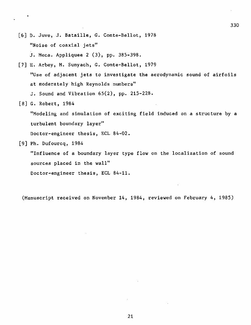
[6] D. Juve, J. Bataille, G. Comte-Bellot, 1978
"Noise of coaxial jets"
J. Meca. Appliquee 2 (3), pp. 385-398.
[7] H. Arbey, M. Sunyach, G. Comte-Bellot, 1979
"Use of adjacent jets to investigate the aerodynamic sound of airfoils
at moderately high Reynolds numbers"
J. Sound and Vibration 65(2), pp. 215-228.
[8] G. Robert, 1984
"Modeling and simulation of exciting field induced on a structure by a
turbulent boundary layer"
Doctor-engineer thesis, ECL 84-02.
[9] Ph. Dufourcq, 1984
"Influence of a boundary layer type flow on the localization of sound
sources placed in the wall"
Doctor-engineer thesis, ECL 84-11.
(Manuscript received on November 14, 1984, reviewed on February 4, 1985)
21


![{NASA-TM-78Ol7) PsONKEPS AS SOURCE OF N86-28625 II … · cellular pneumonia [39]. Most of the animals develop changes in the medulla oblangata and pons * Moscow Scientific-Research](https://img.pdfslide.us/doc/110x75/5d50ce5988c993b11b8bd7bd/nasa-tm-78ol7-psonkeps-as-source-of-n86-28625-ii-cellular-pneumonia-39.jpg)