Embed Size (px)
Citation preview

NASA TECHS:ICAL MEMORANDUM
EFFECTS OF SPOILERS AND GEAR ON B-747
WAKE VORTEX VELOCITIES
A. B. Luebs, J . C . Bradfute, and D. L. Ciffone
Ames Research Center Moffett Field. Calif. 94035
.A
z NASA TM X- 73,197 a
August 1976
.- A .
/" , . . . 1
,' ' , 1. ~
!.
\ >,
IKPIIT BRil:IZH '
(NASA-TM-X-73197) EFFECTS OF SPOILERS AND N77- 18052 GEAR ON i3-747 MAKE VORTEX VELOCITIES (NASA) 25 p HC A02/dP A01 CSCL 018
Unclas G3/02 17197
https://ntrs.nasa.gov/search.jsp?R=19770011108 2018-11-04T19:50:36+00:00Z
'For ule tr+ the National Tchn~crl lnfwnut~on Slrvlce. Sprrngfield. Vlrglnta 22161
1 Rqxvt No. 2. Gomnmnt kcr*on No.
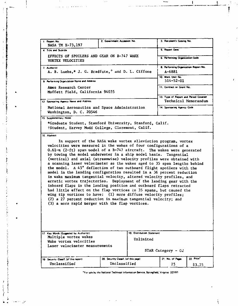
NASA TM X-73,197 4 Title md Subtitle
EFFECTS OF SPOILERS AND GEAR ON B-747 WAKE VORTEX VELOCITIES
7. Author(s1
A. B. Luebs,* J. G. ~radfute,~ and D. L. Ciffone .
9 Psrfarn~rq Orgm~utwn Name 8nd Mdrm
Ames Research Center Moffett Field, California 94035
12 Sponurirq ~ p m c v t&m and ~ d d r c s
National Aeronautics and Space Administration Washington, D. C. 20546
3. Ra~pirntk CIuloq No.
5. ~ e p w t hn
6. Performinp ~qmizat ion Cods
8. Performing Olpnizrtion Report No.
A-6881 10. Work Unit No.
514-52-01
11. contract IN Gnnt NO.
13. Typs of Rapoft a d %~od Cowad
Technical Memorandum
14. ~ p ~ o r i n g A p c y code
15 S~pplemmtary Notes
*Graduate Student, Stanford University, Stanford, Calif. +Student, Harvey Mudd College, Claremont, Calif.
16. Abtrrct
In support of the NASA wake vortex ~lleviation program, vortex velccities were measured in the wakes of four configurations of a 0.61-m (2-ft) span model of a B-747 aircraft. The wakes were generated by towing the model underwater in a ship model basin. Tangential (vertical) and axial (streamwise) velocity profiles were obtained with a scanning laser velocimeter as the wakes aged to 35 span lengths behind the model. A 45O deflection of two outboard flight spoilers with the model in the landing configuration resulted in a 36 percent reduction in wake maximum tangential velocity, altered velocity profiles, and erratic vortex trajectories. Deployment of the landing gear with the inboard flaps in the landing position and outboard flaps retracted had little effect on the flap vortices 20 35 spans, but caused the wing tip vortices to have: (1) more diffuse velocity profiles; (2) a 27 percent reduction in maxim~m tangential velocity; and (3) a more rapid merger with the flap vortices.
17 ~ e y Word, (Suppated bv A~llrhor(r))
Multiple vortex wakes Wake vortex velocities Laser velocimeter measurements
-
18. Distribut~on Statement
Unlimited
STAR Category - 02 19. Snur~tv Omif. (of thn R W ~ )
Unclassified 20. k u r i t v Clr9if. (of this pq)
Unclassified 21. No. of Pqps
25
22. Price'
$3.25

SYMBOLS
wing span, 0.61 m
l i f t c o e f f i c i e n t
LV s i g n a l frequency
LV Bragg C e l l s h i f t e d frequency f S
LDG l and ing conf igura t ion , t r a i l ing-edge f l a p s d e f l e c t e d 46", leading-edge f l a p s deployed
LDG (S)
LDG/O
same a s LDG bu t wi th s p o i l e r s d e f l e c t e d upward 45"
same a s LDG b u t wi th outboard t r a i l ing-edge f l a p s r e t r a c t e d
same a s LDG/O b u t wi th l and ing gear r e t r a c t e d
l a s e r velocimeter
towing speed, m/sec
v o r t e x a x i a l (s treamwise) v e l o c i t y component
v o r t e x t a n g e n t i a l ( v e r t i c a l ) v e l o c i t y component
streamwise p o s i t i o n , p o s i t i v e downstream of wingt ip t r a i l i n g zdge
spanwise p o s i t i o n , p o s i t i v e outboard from fuse lage c e n t e r l i n e i n d i r e c t i o n of r i g h t semlspan
v e r t i c a l p o s i t i o n , p o s i t i v e upward from wingt ip t r a i l i n g edge
model ang le of a t t a c k
u n i t change
i n t e r s e c t i o n ang le of t h e crossed l a s e r beams
index of r e f r a c t i o n
iii

EFFECTS OF SPOILERS AND GEAR ON B-747 WAKE VORTEX VELOCITIES
A. B. Luebs,* J. G. ~ r a d f u t e , ~ and D. L. Cif fone
Ames Research Center
SUMMARY
In suppor t of t h e NASA wake vor tex a l l e v i a t i o n program, v o r t e x veloc- i t i e s were measured i n t h e wakes of f o u r c o n f i g u r a t i o n s of a 0.61-m (2 - f t ) span model of a B-747 a i r c r a f t . The wakes were genera ted by towing t h e model underwater i n a s h i p model bas in . Tangen t i a l ( v e r t i c a l ) and a x i a l (streamwise) v e l o c i t y p r o f i l e s were obta ined wi th a scanning l a s e r velocim- e t e r a s t h e wakes aged t o 35 span l e n g t h s behind t h e model. A 45' d e f l e c t i o n of two outboard f l i g h t s p o i l e r s w i t h t h e model i n t h e landing c o n f i g u r a t i o n r e s u l t e d i n a 36 percent r educ t ion i n wake maximum t a n g e n t i a l v e l o c i t y , a l t e r e d v e l o c i t y p r o f i l e s , and e r r a t i c vor tex t r a j e c t o r i e s . Deployment of t h e l and ing gear wi th t h e inboard f l a p s i n t h e l and ing p o s i t i o n and outboard f l a p s r e t r a c t e d had l i t t l e e f f e c t on t h e f l a p v o r t i c e s t o 35 spans , bu t caused t h e wing t i p v o r t i c e s t o have: (1) more d i f f u s e v e l o c i t y p r o f i l e s ; (2) a 27 percent r educ t ion i n maximum t a n g e n t i a l v e l o c i t y ; and (3) a more r a p i d merger wi th t h e f l a p v o r t i c e s .
INTRODUCTION
This experimental s tudy is p a r t of a concer ted e f f o r t t o reduce t h e hazard p o t e n t i a l of l i f t - g e n e r a t e d wake vort!.ces t r a i l i n g heavy a i r c r a f t . Recent r e sea rch ( r e f . 1 ) h a s e s t a b l i s h e d t h a t t x b u l e n c e produced by f l i g h t s p o i l e r s and favorab le span load g r a d i e n t s induced by s e l e c t i v e f l a p s e t t i n g s a r e e f f e c t i v e i n a l l e v l a t i n g concentra ted wake v o r t i c i t y . Both of t h e s e concepts have been shown ( r e f . 1) t o be a p p l i c a b l e t o t h e B-747 a i r p l a n e . However, i t is not completely understood how land ing gear deployment can adverse ly a f f e c t wake a l l e v i a t i o n obta ined by span load modi f i ca t ion ( r e f . 1 ) o r what flow mechanisms a r e r espons ib le f o r t h e a l l e - v i a t i o n achieved wi th p roper ly placed s p o i l e r s ( r e f . 2) .
To h e l p c l a r i f y t h e s e u n c e r t a i n t i e s , t h i s paper p resen t s q u a n t i t a t i v e measurements obta ined i n t h e wake downstream of a B-747 a i r c r a f t model configured wi th s p o i l e r s and f l a p s t o a l l e v i a t e concentra ted wake v o r t i c i t y . The experiment was performed i n t h e Univers i ty of C a l i f o r n i a ' s s h i p model b a s i n a t Richmond, C a l i f o r n i a . Time-dependent t a n g e n t i a l ( v e r t i c a l ) and
*Graduate Student , S tanford Univers i ty , Stanford , C a l i f . tS tuden t , Harvey Mudd College, Claremont, C a l i f .

a x i a l (streamwise) v e l o c i t y d i s t r i b u t i o n s i n t h e wakes of a 0.61-m (2-f t ) span model were measured wi th a scanutng l a s e r velocimeter . Data were obtained t o d i s t a n c e s of 35 span l eng ths behind t h e model. The model was f i t t e d wi th removable t r i p l e - s l o t t e d f l a p s , f l i g h t s p o i l e r s , and landing gear. The mean chord t e s t Reynolds nuniber was 82,000.
EXPERIMENTAL APPARATUS AND PROCEDURE
F a c i l i t y and Model Descr ip t ion
The Univers i ty of C a l i f o r n i a ' s s h i p model basj?, l o c a t e d i n Richmond, Califor::ia, is 61 m long, 2.44 m wide, and 1 .7 m de p. The model was s t r u t - mounted t o an e l e c t r i c a l l y d r iven c a r r i a g e and towed through t h e water p a s t a viewing s t a t i o n ( f i g . 1 ) . A t t h i s s t a t i o n , l a r g e g l a s s windows i n t h e s i d e of t h e tank a l low t h e model wake t o be observed a s i t ages and descends. A l l d a t a were obta ined at a towing speed of 1 m/sec.
Four conf igura t ions of a 0.01 s c a l e model of a B-747 a i r c r a f t were t e s t e d ( f i g . 2) : (1) landing, LDG, wi th inboard and outboard f l a p s d e f l e c t e d 46' and leading-edge f l a p s extended; (2) LDG (S), same as LDG but wi th two outboard f l i g h t s p o i l e r s d e f l e c t e d upward a t 45'; (3) LDG/O, same a s LDG but wi th outboard f l a p s r e t r a c t e d ; and (4) LDG/O (CR), same a s LDG/O but wi th landing gear r e t r a c t e d . The s p o i l e r s were l o c a t e d forward of t h e outboard h a l f of t h e outboard f l a p from 0.59 t o 0.69 of t h e semispan ( f i g . 2) . To a l low observat ion of t h e wake v o r t i c e s t h a t it genera tes i n t h e wa te r , t h e model i s equipped wi th dye-ejection o r i f i c e s ( r e f . 3).
Experimental Procedure
It has been concluded t h a t t h e s c a l i n g laws f o r modeling f l u i d phenomena, p e r t i n e n t t o t h e study of wake v o r t i c e s , a r e e s s e n t i a l l y t h e same f o r tests i n water a s i n air ( r e f s . 4-7), and t h a t t h e f o r c e s a c t i n g on h y d r o f o i l s operated a t depths g r e a t e r than two chord l e n g t h s a r e e s s e n t i a l l y unaffected by t h e f r e e s u r f a c e and a r e equal t o those obtained on a wing opera t ing i n an i n f i n i t e medium ( r e f . 8). The model c e n t e r l i n e i n t h e s e tests was loca ted approximately f i v e chord l eng ths (0.75 of a span) below t h e f r e e su r face . Although t h e t e s t Reynolds number (82,000 based on chord) was considerably l e s s than f u l l s c a l e , general agreement i n wake appearance ( r e f . 1 ) and vor tex t r a j e c t o r i e s (ref . 9) was ev iden t comparisons could be made wi th f l i g h t d a t a . Wake d a t a obtained i n t h i s test should, t h e r e f o r e , be i n d i c a t i v e of f l i g h t r e s u l t s . This seeming l a c k of Reynolds number s e n s i t i v - i t y does n o t come a s a complete s u r p r i s e s i n c e previous wake vor tex v e l o c i t y measurements obta ined i n t h i s f a c i l i t y ( r e f . 5) on a v a r i e t y of wing config- u r a t i o n s c o r r e l a t e d wel l ( r e f . 10) wi th both wind-tunnel and f l i g h t measure- ments.
Dye was emit ted from t h e model t o a l low v i s u a l t r ack ing of t h e wake v o r t i c e s a s they moved through t h e water . I n add i t ion , t h e viewing s e c t i o n

of the tank was seeded with polystyrene copolymer latex spheres to provide sufficient scattering particles to ensure laser velocimeter signals with adequate strength and resolution. The combination of a small particle size (2 to 15 LI diameter) and a specific gravity of 1.06 for these spheres ensures flow-tracing fidelity. The laser velocimeter began scanning the flow field prior to the model's arrival at the viewing station, and the timing for a run was initiated as the streamlined strut passed the outgoing laser beams. During each run, the elevation of the laser velocimeter was kept constant and the aging vortices allowed to descend through the LV's optical axis. After each run, the carriage was returned to the starting end of the tank, and the laser was used to monitor water motion to ensure a calm tank prior to the next run (eddy velocities 50.004 m/sec). At a towing speed of 1 mlsec, the laser scanning rate was such that the rate of change of the age of the wake with lateral position of the focal point of the laser beams was A(X/b)/A(Y/b/2) = 2. Hence, during the scan of the vortex cores, the wake aged approximately one-third of a spsn (-0.2 sec).
Data Acquisition and Presentation
The trailing vortex flow was spatially scanned using the single com- ponent laser velocimeter shown installed at the viewing station of the tank, in figure 1, and schematically in figure 3. A prism splits the green (5145 A) output beam of the argon-ion laser into two parallel beams, one of which is then frequency-shifted 40 MHz by a Bragg Cell to achieve directional sensitivity in the signal. The two beams then pass through a scanning lens, which is mounted on a motorized slide, and are subsequently crossed at a focal point in the water by the collector lens. The beam splitter prism and Bragg Cell can be rotated as a unit to measure vertical or streamwise flow velocities. Light scattered from particles at the focal point is collected through the same optical system and focused onto a photomultiplier tube. The frequency detected by the photomultiplier is linearly related to flow- field velocity by
(5145 A) (f - fs) v = 2u sin 812
where fs is the Bragg Cell shift freqaency, 40 MHz. This equation represents the vortex axial velocity Vx or tangential velocity, Vz (depending on the orientation of the LV) when a core centerline penetration of the vortex is achieved. The crossing angie 0 of the two laser beams and the distance of their focal point from the tank wall are dependent on the scanning lens posi- tion. The index of refraction of water was used in the above equation (u = 1.33).
A spectrum analyzer and signal sampler vere used to process the photo- multiplier output dignal. The signal sampler provided an analog output proportional to frequency. This voltage, together with the voltage across potentiometers mounted on the scanning lens mechanism and the lift supporting the laser, was digitized and recorded on tape. During the interval between test runs, while water motions were settling, the data stored on tape from

t h e just-completed test run were reduced and p l o t t e d . This o n s i t e da ta review c a p a b i l i t y g r e a t l y a s s i s t s i n providing r e p r e s e n t a t i v e d a t a i n a mini- mum amount of test runs , and a l lows f o r f u r t h e r i n v e s t i g a t i o n o f unexpected r e s u l t s .
Flow f i e l d v e l o c i t i e s a r c presented a s f r a c t i o n s of towing speed lJm. Streamwise p o s i t i o n X ( p o s i t i v e downstresm) , spanwise p o s i t i o n Y (posi- t i v e outboard along t h e r i g h t semispan), and v e r t i c a l p o s i t i o n Z ( p o s i t i v e upward) a r e nondimensionalized by wingspan b. The o r i g i n of t h e s e coordi- n a t e s is t h e p ro jec ted l o c a t i o n of t h e wingt ip t r a i l i n g edge onto t h e fuse lage c e n t e r l i n e .
DISCUSSION OF RESULTS
The wakes of four conf igura t ions of t h e B-747 model were i n v e s t i g a t e d . Velocity p r o f i l e s through t h e wake v o r t i c e s were measured and compared a t t h r e e v e r t i c a l p o s i t i o n s below t h e model. These p o s i t i o n s were Z/b = -0.16 (nearf i e l d ) , -0.44 (midf ie ld ) , and -0.69 ( f a r f i e l d ) . Of primary i n t e r e s t was t h e e f f e c t of s p o i l e r s on t h e LDG conf igura t ion and t h e e f f e c t of landing gear on t n e LDG/O conf igura t ion . The r e s u l t s a r e presented a s : (a) ran- g e n t i a l and a x i a l v e l o c i t y p r o f i l e s f o r t h e dominant v o r t i c e s ( f i g s . 5-8); maximum vor tex v e l o c i t y downstream dependence ( f i g s . 9 and 1 0 ) ; and (c) vor tex t r a j e c t o r i e s ( f i g s . 11 and 12) .
Vortex Veloci ty P r o f i l e s
I n t h e landing conf igura t ion , t h e B-747 sheds f i v e v o r t i c e s from each s i d e of t h e wing. Four of t h e s e v o r t i c e s a r e due t o t h e span-loading gradi- e n t s caused by t h e f l a p s and t h e f i f t h is due t o t h e span-load gradient a t t h e wing t i p . The dominant v o r t e x is shed from t h e outboard edge of t h e outboard f l a p . The wing t i p vor tex merges wi th t h i s vor tex , and the r e s u l t is a p e r s i s t e n t vor tex. It has been e s t a b l i s h e d ( r e f . 1 ) t h a t a 45" d e f l e c t i o n of t h e two outboard f l i g h t s p o i l e r s ( f i g . 2) r e s u l t s i n a 15 t o 50 percent reduct ion of t h e r o l l i n g moment on an encountering a i r c r a f t , depending on t h e wing span r a t i o of generator t o fol lower ( r e f s . 1 , 2 ) . However, t h e mechanism of i n t e r a c t i o n between s p o i l e r and vor tex is not completely understood.
The measured e f f e c t of s p o i l e r s Jn t h e t a n g e n t i a l v e l o c i t y p r o f i l e of t h e dominant vor tex i n t h e wake of t h e LDG conf igura t ion is shown i n f i g u r e 5. The models' two outboard f l i g h t s p o i l e r s were d e f l e c t e d upward 45'. L i f t c o e f f i c i e n t wi th and without s p o i l e r s was kept a t a nominal va lue of 1 .3 by a d j u s t i n g model angle of a t t a c k . I n t h e nearf i e l d ( a t Z/b = -0.16), t h e s p o i l e r s inc rease t h e vor tex s i n k r a t e by an average of 48 percent and reduce t h e maximum t a n g e n t i a l v e l o c i t y by 28 percen t , ' Hence, wi th s p o i l e r s , t h e
' Maximum t a n g e n t i a l v e l o c i t y i s def ined a s t h e average va lue of inboard and outboard peak t a n g e n t i a l v e l o c i t y from a given v e l o c i t y p r o f i l e . Vortex s i n k r a t e is es t imated from t h e p o s i t i o n of t h e v o r t e x c e n t e r wi th respec t t o zero v e l o c i t y .
4

f l a p vortex a r r i v e s a t t h i s nea r f i e ld v e r t i c a l s t a t i o n two span lengths sooner and has a lower tangent ia l ve loc i ty . Negative v e r t i c a l ve loc i ty components r e s u l t i n g from the downward motion of the vortex cause t h e ve loc i ty p r o f i l e t o be biased downward toward negat ive values of t angent ia l ve loc i ty . The da ta of f i gu re 5 have not been corrected f o r t h i s motion. Although the saddle shapc of t he ve loc i ty p r o f i l e a t t he 0.7 semispan pos i t ion fo r the LDG (S) configuration appears a t a spanwise loca t ion j u s t behind the outboard edge of t he spo i l e r s , it is believed tha t t h i s region of low veloci ty is the r e s u l t of the l ike-s ign wingtip vortex merging with t h e f l a p vortex. The same depression is not seen i n t he LDG configurat ion ve loc i ty p r o f i l e because, by 7.2 span lengths , t h e merging process has been completed ( r e f . 3 ) , and only t he s ing l e f l a p vortex is dis t inguishable .
I n the midfield ( a t Z/b = -0.44) the averhge vortex s ink r a t e of each configurat ion increased s l i g h t l y , while t h e i r maximum tangent ia l ve loc i ty did not change. Figure 5 shows the major e f f e c t of the s p o i l e r s a t t h i s s t a t i o n t o be a more d i f fu se f l a p vortex with a broadened core. However, some of t h i s broadening may be due t o vortex curvature i n t he plane orthogonal t o the one containing the l a s e r beams. A t t h i s loca t ion below the model, the LDG (S) f l a p vortex i s moving l a t e r a l l y i n an e r r a t i c path toward the obser- va t ion windows (vortex t r a j e c t o r i e s a r e discussed l a t e r ) . The f l a p and wing- t i p merger has been completed a t t h i s s t a t i o n and the saddle shape i n the ve loc i ty p r o f i l e of the LDG (S) configurat ion is no longer evident. Further downstream a t X/b = 27.2, 28.3 and Z/b = -0.69, the maximum tangent ia l v e l o c i t i e s remain unchanged, t he average vortex s ink r a t e of t he LDG (S) configurat ion has slowed and become comparable t o t h a t of t he LDG configura- t i on , and the ve loc i ty p r o f i l e of the LDG (S) configurat ion shows a recon- cen t ra t ion of v o r t i c i t y (reduced core s i z e ) . While the r e l a t i v e l y small core diameter indicated by the LDG (S) ve loc i ty p r o f i l e is su rp r i s ing and sugges- t i v e of an off-center core penetrat ion, t he magnitudes of t angent ia l ve loc i ty agree with the r e s t of f i gu re 5 and the apparent reconcentrat ion of v o r t i c i t y are i n agreement with flow v i sua l i za t i on s tud i e s ( r e f . 6) .
In the LDG/O (GR) configurat ion, the outboard f l a p is r e t r ac t ed and th ree vo r t i ce s a r e shed from each s i d e of the wing - one from each s i d e of t h e inboard f l a p and the wingtip. F i r s t , t he vortex from t h e inboard s i d e of the f l a p merges with the one from the f l aps ' outboard s ide ( r e f . 11) , and then t h e wingtip vortex moves inboard and merges with t h i s r e su l t i ng f l a p vortex, causing a very d i f fu se res idua l vortex. Compared t o t he landing configurat ion, reductions of 50 percent i n r o l l i n g moment on an encountering a i r c r a f t (depending on the wing span r a t i o of generator t o follower) have been measured fo r t h i s LDG/O (GR) configurat ion ( r e f . 1 ) . However, i t is not completely understood why t h e vortex reconcentrates when the landing gear is deployed.
The measured e f f e c t of landing gear i s shown i n a comparison of the LDG/O (GR) vortex ve loc i ty p r o f i l e s of f igures 6 t o 8. Tangential ve loc i ty p r o f i l e s from the outboard vortex of the f l a p and from the wingtip a r e compared i n f igures 6 and 7, respec t ive ly , while f i gu re 8 compares f l a p a x i a l ve loc i ty p ro f i l e s . L i f t coe f f i c i en t was 1.16 f o r a l l of t h i s data . Although reference 11 suggests a d i f fe rence i n the merging c h a ~ a c t e r i s t i c s of t he f l a p

vor t i ce s due t o t he presence of t h e landing gear. Figure 6 ind ica tes t h a t within the s c a t t e r of t he da t a , t he landing gear does not appear t o a f f e c t e i t h e r the magnitude o r p r o f i l e of the f l a p vortex tangent ia l ve loc i ty t o 29 span lengths behind the model. This vortex is qu i t e concentrated and has high tangent ia l v e l o c i t i e s i n the near f ie ld . The upvash seen i n the ve loc i ty p r o f i l e i n the v i c i n i t y of t he wingtip f o r t he LDG/O configurat ion a t Z/b = -0.44 and -0.69 is probably associated with r e s idua l v e l o c i t i e s from the wingtip vortex a f t e r merger with t he f l ap . This merger is completed by about 21 spans. The presence of the landing gear does a f f e c t t he wingtip vortex ve loc i ty p r o f i l e i n t h i s configuration. This is shown i n f i gu re 7. A t 7 t o 8 spans behind the model, t h e wingtip vortex i s located above and inboard of the f l a p vortex ( r e f . 3) and is moving rap id ly downward. This rapid downward movement V,/U, -0.075 is the reason t h a t t he measured ve loc i ty p r o f i l e s a t Z/b = -0.154 a r e almost e n t i r e l y negative. For t he LDG/O (GR) configurat ion, the wingtip vortex is very concentrated and well- defined. The presence of t he landing gear makes the vortex more d i f f u s e and reduces its maximum tangent ia l ve loc i ty by 27 percent. The upwash evident i n the ve loc i ty p r o f i l e over the outer half of the semispan is due t o c i rcu la - t i o n from the f l a p vortex, which is outboard and below the t i p vortex. A t 12 span lengths behind the model, t he wingtip vortex has moved downward t o a posi t ion almost d i r e c t l y inboard of the f l a p vortex. The increased f luctua- t i ons i n the ve loc i ty p r o f i l e s over t he outboard s ec t ion of the semispan a r e due t o the c loser proximity of t he f l a p vortex. Due t o t he gear , the LDG/O i i p vortex is s t i l l more d i f f u s e and has lower tangent ia l v e l o c i t i e s than the LDG/O (GR) configuration. A t t h i s s t a t i o n , the LDG/O t i p vortex i s a l s o f a r the r outboard, which is cons is ten t with flow v i sua l i za t i on r e s u l t s ( r e f . 3). These flow v i sua l i za t i on s tud i e s a l so i nd i ca t e t h a t t he wingtip vortex merges with t he f l a p vortex a t -18 span lengths when the gear i s deployed and is delayed t o -21 spans when the gear i s r e t r ac t ed . Figure 7 suggests t h i s a t a v e r t i c a l posi t ion of 0.69 span below the model where a wingtip vortex tangent ia l ve loc i ty p r o f i l e was measured f o r t h e LDG/O (GR) configurat ion a t 21.4 spans, but none was measurable fo r the gear-retracted configuration. A t t h i s s t a t i o n , the LDG/O (GR) wingtip vortex is below and outboard of the f l a p vortex, the loca t ion where merger general ly occurs ( r e f . 3) .
Axial ve loc i ty p r o f i l e s of the f l a p vortex f o r t h e LDG/o and LDG/O (GR) configurations a r e shown i n f i gu re 8 . Since t h i s l a s e r velocimeter can measure only one ve loc i ty component a t a time, these p r o f i l e s were taken separately from the data of f i gu re 6 , It is seen t h a t a t Z/b = -0.16, the f l a p outboard edge vortex has a c l ea r ly defined a x i a l ve loc i ty defect . An a x i a l ve loc i ty defect being defined a s ( 1 - V,/U,) > 1.0 and represent ing a streamwise flow i n t he core of the v o r t e x , i n an upstream d i r ec t i on towards the model. Figure 8 shows tha t by the time t h i s vortex has descended t o 0.44 span below the model, f l uc tua t ions appear i n the a x i a l ve loc i ty p r o f i l e f o r the LDG/O (GR) configurat ion. These f l uc tua t ions a r e a consequence of t \e wingtip vortex-flap vortex merger. For t he LDG/O (GR) configurat ion, the merger i s i n i ts f i n a l s tages and a double peak is seen i n the ve lg~ci ty p ro f i l e . Axial v e l o c i t i e s fo r t he LDG/O configurat ion were measured a t e a r l i e r times a t t h i s v e r t i c a l s t a t i o n , and the merging process was not a s f a r along. The maximums i n ve loc i ty a t 0.55 and 0.8 semispan is due t o the f l a p and wingtip vo r t i ce s , respect ively. Axial flow enhancement seen a t

severa l pos i t ions along t h e semispan fo r t he LDG/O configurat ion might be due i n p a r t t o a measured a x i a l component r e s u l t i n g from a downward curvature of the vortex. A t Z/b = -0.69, there is s t i l l evidence of vor tex merger i n t he LDG/O configurat ion; both ve loc i ty p r o f i l e s have become q u i t e d i f fuse . In summary, t h e e f f e c t of landing gear on the a x i a l ve loc i ty p r o f i l e of t h e f l a p outer-edge vor tex appears t o be a reduct ion i n ve loc i ty defec t and a more d i f fu se core . The reduced ve loc i ty defec t is surpr i s ing , s i n c e it was an t ic - ipated t ha t the gear drag would r e s u l t i n an increased a x i a l ve loc i ty defec t . Perhaps the momentum defec t associated with the gear does not become trans- ported i n t c the vortex core u n t i l f u r the r downstream.
Vortex Maximum Veloc i t ies
Comparisons of the downstream dependence of vortex maximum tangent ia l ve loc i ty normalized by l i f t coe f f i c i en t , f o r t he conf igura t ions t e s t e d , is presented i n f i gu re 9. The v e l o c i t i e s of the outboard f l a p outer-edge vortex f o r both t he LDG and the LDG (S) configurat ions d i sp lay t he now famil- i a r plateau ( r e f . 5 ) . Although, f o r these configurat ions, t he re is l i t t l e decay i n t h e normalized maximum v e l o c i t i e s once wake ro l l up and merging have been completed ( - ~ / b > 6), t he s p o i l e r s reduce t h i s ve loc i ty by 35 percent. I n con t r a s t , there is l i t t l e , i f any, e f f e c t of t he landing gear on t h e maximum ve loc i ty of t he inboard f l a p outer-edge vortex, and no plateau region is evident f o r t h i s vortex. The absence of t h e p la teau is due t o t he longer time required f o r t he wingtip-flap vortex merger, The flow v i sua l i za t i on ind ica tes t h a t t h i s merger is not completed u n t i l -18 t o 20 span lengths down- stream, and the ve loc i ty p r o f i l e s ( f i g . 6) suggest t h a t it may go on longer than t h a t . A t 30 span lengths downstream, the wake maximum t angen t i a l ve loc i ty of the LDGIO and LDG (S) configurat ions is comparable. However, there is evidence ( r e f s . 1,7) t h a t fu r the r downstream the LDG/O f l a p vortex experiences a reconcentration of v o r t i c i t y . Also shown i n f i gu re 9 is the LDG/O l a s e r velocimeter wind tunnel r e s u l t of r , t ference 12. The hgreement with t he present measurements is surpr i s ing ly good (within 17 percent) considering the d i f f i c u l t y of making these n e s r f i e l d measurements.
A l imited number of streamwise v e l o c i t i e s were measured f o r t he LDG, LDGIO and LDG/O (GR) configurat ions. The va r i a t i on of f l a p vortex maximm a x i a l ve loc i ty defec t with downstream d is tance fo r these configurat ions is shown i n f i gu re 10. The vortex core streamwise ve loc i ty towards t h e model f o r the LDG configurat ion remains constant a t about 12 percent of t he towing speed from 5 t o 25 spans behind the model. For the LDG/O and LDG/O (GR) configurat ions, t h e vortex a x i a l ve loc i ty defec t is 50 percent higher i n t he nea r f i e ld , p r io r t o merger of t he f l a p and wingtip vortex.
Vortex T ra j ec to r i e s
Although the primary purpose of t h i s experiment did not include obtain- ing vortex t r a j ec to ry information, vortex-position t ime-his tor ies can b e he lpfu l i n explaining the measured ve loc i ty p r o f i l e s . Vortex t r a j e c t o r i e s can be only roughly deduced from ve loc i ty measurements a t j u s t th ree

e leva t ions below the model. For t h i s reason, the t r a j ec to ry information presented i n f i gu re s 11 and 12 has been supplemented with t he flow v i sua l i - za t ion d a t a of reference 6. These f i gu re s r e l a t e prominent vor tex spanwise and v e r t i c a l loca t ion . Figure 11 shows what e f f e c t two outboard f l i g h t s p o i l e r s have on the t r a j ec to ry of t he vortex shed from the outboard edge of t ne outboard f l a p i n the landing configuration. The l a s e r and flow v i eua l i . - - t i o n data show the same general t rend - w i t h spo i l e r s , the vortex i n i t i a l l y moves fu r the r inboard o f , then fu r the r outboard o f , and eventual ly ~pproaches the path o f , tLe vortex without spo i l e r s . The t r a j ec to ry with spo i l a r e is i much more e r r a t i c and, fo r t he f i r s t 25 spans behind the model, i t descends much more rap id ly ( re f . 6) . Figure 11 shows t h a t a t about 0.4 span be: ow the model, the movement of t h i s vortex in the v e r t i c a l plane is almost e n t i r e l y l a t e r a l i n t he outboard d i r e . t i o n . Figure 12 shows the t r a j e c t o r i e s of the outboard edge f l a p vortex and wing t i p vortex f o r the LDG/O and LDG/O (GR) configurat ions. Selected X/b's a r e noted on the f i gu re t o allow r e l a t i v e pos i t ion comparisons. The e f f e c t of t he landing gear on the f l a p vortex t r a j e c t o r y was negl ig ib le t o 30 spans. A t 12 span lengths downstream of t he model, with gear deployed, the wing t i p vortex begins t o move outboard sooner. This is suggested by the l a s e r da ta presented i n t he f i gu re and is q u i t e evident i n t he flow v i sua l i za t i on da ta of references 6 and 7. No l a s e r da ta f o r t he wing t i p vor tex with gear extended is shown beyond 12 span lengths due t o its accelerated outboard movement r e su l t i ng i n a merger with t he f l a p vor tex before the next v e r t i c a l test pos i t ion was reached ( f i g . 7) . For reasons of c l a r i t y , only gear-retracted flow v i sua l i za t i on da ta a r e pre- I
seuted i n t h e f igure . The agreement between the l a s e r and flow v i sua l i za t i on . data is good.
SUMMARY AND CONCLUSIONS
The wakes of four configurat ions of a B-747, 0.01 sca l e (0.61-m span) model t ranspor t a i r c r a f t were invest igated. The wake v e l o c i t i e s were mea- sured a t th ree d i f f e r e n t v e r t i c a l positions below the model and tqmpared i n an attempt t o determine the e f f e c t s of f l i g h t spo i l e r s and 1andih.g gear. The following is a summary of the r e s u l t s of t h i s experimental inves t iga t ion :
(1) A t a l i f t coe f f i c i en t of 1.3, the following changes were noted i n t he wake of the landing configurat ion when the two outboard f l i g h t spo i l e r s were deployed a t 45' def lect ion: (a) the maximum tangent ia l ve loc i ty of the wake's pe r s i s t i ng vortex (shed from the outboard edge of the outboard f l ap ) was reduced by 36 percent from the 5 t o 28 span lengths behind the model where v e l o c i t i e s were recorded; (b) a t 12 spans, the f l a p vortex was q u i t e d i f fu se , but oy 28 span lengths its v o r t f c i t y appeared t o be reconcentrating; (c) the vortex t r a j ec to ry was more e r r a t i c , s inking almost twice a s f a s t and moving fu r the r inboard a t 5 span lengths , and then swinging fu r the r outboard a t 12 span lengths. However, i t . eventual ly s e t t l e d down and approached the t r a j ec to ry of the unspoiled con- f i gu ra t i on by 28 span lengths . These l imited r e s u l t s suggest t h a t the major inf luence of spo i l e r s on the wake r e s u l t s from t h e i r generation of turbulence.

A. a l i f t coe f f i c i en t of 1.2, t he following changes were noted i n the wake of t he landing configurat ion with outboard f l a p s r e t r ac t ed , a s a r e s u l t of landing gear deployment: (a) the wing t i p vortex was more d i f fu se a s it orb i ted about t he outboard edge f l a p vortex, its maximum tangent ia l ve loc i ty was reduced by 27 percent , and i t merged sooner with the f l a p vortex; (b) contrary t o what was expected, the f l a p vortex had less of an a x i a l vc loc i ty defec t although i t s core was more d i f fuse . The weakening of the wing t i p vortex appears t o be asso=iated with its passage through t h a t por- t i o n of t he wake t h a t i s transporting landing gear turbulence. This weakening r e s u l t s i n t he wiarg t i p vortex merging sooner with the l i k e s ign f l ap vortex. A t 29 span lengths behind the model, there was s t i l l no evidence of t he res idua l , merged, f l a p vor tex recon- cen t r a t i ng its v o r t i c i t y . Hence, it is s t i l l not evident how the landing gear adversely a f f e c t s the f l a p vortex.

REFERENCES
2 . NASA Symposium on Wake Vortex 'Minimization, NASA SP-409, 1976.
2. Corsiglia, V. R.; and Rossow, V. J.: Wind-Tunnel investigation of the Effect of Porous Spoilers on the Wake of a Subsonic Transport Model. NASA TM X-73,091, 1976.
3. Ciffone, D, L.: Vortex Interactions in Mt ,:iple Vortex Wakes Behind Aircraft. J. Aircraft, April 1977.
4. Kirkman, K. L.; Brown, C. E.; and Goodman, A.: Evaluation of Effective- nees of Various Devices for Attenuation of Trailing Vortices Based on Model Test in a Large Towing Basin. NASA CR-2202, 1973.
5. Ciffone, D. L.; and Orloff, K. L.: Far-Field Wake-Vortex Characteristics of Wings. J. Aircraft, vol. 12, no. 5, May 1975, pp. 464-470.
6. Ciffone, D. L.: Alleviation and Ground Plane Effects on DC-10-30 and B-747 Wakes. Paper to be presented at Conference on Aircraft Wake Vortices, March 1977, U. S. Department of Transportation.
7. Ciffone, D. L.; and Lonzo, C.: Flow Visualization of Vortex Interactions in Multiple Vortex Wakes Behind Aircraft. NASA TM X-62,459, 1975.
8. Wadlin, K. L.; Ramen, J. A.; and McGehee, J. R.: Tank Tests at Sub- cavitation Speeds of an Aspect Fiatio 10 Hydrofoil with a Single Strut. NACA RM L9K14a, 1950.
9. Brashaars, M.; Zalay, A. D.; and Hallock, J.: Laser Doppler Flight Test Meascrement~ of B-747 Wake Vortex Characteristics. Lockheed-Huntsville Reseerch and Engineerinp, tenter. Paper to be presented at Conference on Aiicraft Wake Vortices, March 1977, U. S. Department of Transporta- t icn .
10. Iversen, J. D.: Correlation of Turbulent Trailing Vortex Decay Data. J. Aircraft, vol. 13, no. 5, 1976, pp. 338-342.
11. Corriglia, V, R.; Rorrow, V. J.; and Ciffone, D. L.: Experimental Study of the Effect of Span Loading on Aircraft Wakes. J. Aircraft, vol, 13, no. 12, December 1976, pp. 968-973.
12, Coreiglia, V. R,; and Orloff, K. L.: Scanning Laber Velocimeter Surveys and Analysis of l*lulriple Vortex Wakes of an Aircraft. NASA TM X-73,169, 1976.


FLAPS ZERO
LANDING
SECTION A-A DETAILS
INBOARD FLAP
OUTBOARD FLAP TEST SPOILERS
ALL DIMENSIONS, cm
Figure 2 . - 0.01 sca le model of Boeing 747 airplane.

1.
AR
GO
N L
AS
ER
(6
wa
tt)
7.
SC
AN
NIN
G L
EN
S
2.
MIR
RO
R
8.
CO
LL
EC
TO
R L
EN
S
3.
BE
AM
RA
ISE
R
9.
MIR
RO
R
4.
BE
AM
SP
LIT
TE
R &
BR
AG
G C
EL
L
10.
LE
NS
5.
M
IRR
OR
WIT
H 4
HO
LE
S
11.
PH
OT
OM
UL
TIP
LIE
R T
UB
E
6.
SC
AN
NIN
G M
EC
HA
NIS
M
TR
AN
SM
ITT
ED
LIG
HT
(51
45 A
. GR
EE
N)
--- R
EC
EIV
ED
LIG
HT
Figure 3.-
Data acquisition and reduction system schematic.
ST
RE
AM
WIS
E
VE
LO
CIT
Y.
Vx
1
L
- - \2
4 --
- -
L
- !I
- &'3
6 -
- --
d -
- --
--
- -
8 -
8
10
v
4
t

DIG
ITA
L
OU
T
TY
PE
WR
ITE
R
m
PR
OG
RA
MM
AB
LE
C
AL
CU
LA
TO
R
TR
AN
SIE
NT
C
AP
TU
RE
DE
VIC
E
(i) 4
CH
AN
NE
L
MU
LT
IPL
EX
(ii)
AID
CO
NV
ER
TE
R
(iii
) T
AP
E C
AS
SE
TT
E
ST
OR
AG
E
SIG
NA
L
DIG
ITA
L P
LO
TT
ER
SP
EC
TR
UM
A
NA
L Y
ZE
R
Figure 4.- Laser velocimeter schematic.
Parallel light beams oriented
to measure streamwise velocity.
(HO
RIZ
) *-
A A
SIG
NA
L O
UT
4
- - (VE
LO
CIT
Y)
(VE
RT
)
FR
EQ
UE
NC
Y
I
SIG
NA
L
SA
MP
LE
R
- -
x P
OS
ITIO
N
RA
MP
GE
NE
RA
TO
R
- -
1
y P
OS
ITIO
N
LA
SE
R
VE
LO
CIM
ET
ER
.
z P
OS
ITIO
N

C
h 0 LOG CL = 1.27 a 2.9' 0 LDG (S) CL = 1.35 6.8'
0 x l b = 7.2 0 xlb = 4.9
Figure 5.- Effect of flight spoilers on flap vortex tangential velocity profile. Landing configuration.

Figure 6.- Effect of landing gear on f lap vortex tangential ve loc i ty prof i le . LDG/O con£ iguration, CL = 1.16, a = 5.8'.

0 xlb = 8.1 0 x/b = 7.1
zlb = -0.154
I L 1 l l l L 1 ~ l l l ' l
o x/b = 11.8 o x/b = 11.9
zlb = -0.44
Figure 7 . - Effect of landing gear on wing t i p vortex tangential velocity pro f i l e . LDG/O configuration, CL = 1.16, a = 5.8'.

0 LDGIO (GR) 0 LDGIO
. . L . 1. -. .L L. .... I - - .L.--L- 1 - 1
Figure 8.- Effect of landing gear on f lap vortex axia l ve loc i ty pro f i l e . LDG/O configuration, CL = 1.16, a = 5.8'.

0 LDG, CL = 1.27, ol = 2.9' h - LDG (S), CL = 1.35, a = 5.8' h
A LDGIO (GR) 0. LDGIO } CL = 1.16, a = 5.8'
h A LDGIO, REF. 12
FAlRlNGTHRU 0 DATA ..
FAIRING THRU 0 DATA -- ' _I
Figure 9.- Downstream dependence of flap vortex maximum tangential velocity.

FA
IRIN
G T
HR
U D
AT
A
Figure 10.- Downstream dependence of flap vortex m
axiu
um axial velocity
defect.

FLOW VISUALIZATION DATA, REF. 6 -- LDG (S), CL = 1.35, cr = 5.8'
LDG ,CL = 1 . 2 7 , ~ ~ = 2 . 9 ~
LV DATA
0 LDG (S), CL = 1.35, a = 5.8' LDG ,C~=1.27,cr=2.9'
Figure 11.- Effect of f l ight spoilers on flap vortex trajectory. Landing configuration.

xlb =
DATA
-.6 FLAP VORTEX: \ \
0 LDG/O 1 O LDGIO (GR)
-.8 1 WING TIP VORTEX: xlb = 29' \ ' x/b = 21.5
t A LDGIO 0 LDGIO (GR)
FLOW VISUALIZATION DATA, REF. 6 LDGIO (GR), FLAP VORTEX
-- LDGIO (GR), WING TIP VORTEX
Figure 12 . - Effect of landing gear on f l a p and wing t i p vortex trajectories, CL - 1.16, a - 5.8'.