Embed Size (px)
Citation preview
NASA TECHNICAL NOTE
00 0 40
T n z c 4 m 4 z
- N A S A - - TN e . /
--- D-3608
COMPARISON OF EXPERIMENTAL A N D THEORETICAL STRESSES AT A MISMATCH I N A CIRCUMFERENTIAL J O I N T I N A CYLINDRICAL PRESSURE VESSEL
by WiZZium C. Morgun und, Peter T. Bizon
Lewis Reseurch Center CZeveZuad, Ohio
1 N A T I O N A L AERONAUTICS A N D SPACE A D M I N I S T R A T I O N W A S H I N G T O N ,i
https://ntrs.nasa.gov/search.jsp?R=19660026833 2018-06-02T20:51:21+00:00Z
TECH LIBRARY KAFB. NM
I 111111 11111 lllll l11l1 I WII 111 ill 1111 0130328
COMPARISON OF EXPERIMENTAL AND THEORETICAL STRESSES
A T A MISMATCH IN A CIRCUMFERENTIAL JOINT IN A
CYLINDRICAL PRESSURE VESSEL
By Wil l iam C . Morgan and Peter T. Bizon
Lewis R e s e a r c h C e n t e r Cleveland, Ohio
NATIONAL AERONAUTICS AND SPACE ADMINISTRATION
For sale by the Clearinghouse for Federal Scientific and Technical Information Springfield, Virginia 22151 - Price $1.00
COMPARISON OF EXPERIMENTAL AND THEORETICAL STRESSES AT A MISMATCH
IN A CIRCUMFERENTIAL JOINT IN A CYLINDRICAL PRESSURE VESSEL
by W i l l i a m C. M o r g a n a n d Peter T. B i z o n
Lewis Research Center
SUMMARY
An experimental evaluation was made of a theoretical analysis of the elastic s t ress
The test cylinders used in the in- distribution at a mismatched circumferential junction between thin-walled, internally pressurized cylinders (nominal s t ress field, 2 to 1). vestigation were of uniform wall thickness but had dissimilar radii on each side of the junction.
Stress distributions were determined with electric-resistance strain gages which were mounted on the interior and exterior walls of four test cylinders, each with a differ ent mismatched junction. Three cylinders were provided with tapered-fillet discontinu- ities of various degrees of mismatch; the fourth cylinder was made with an abrupt dis- continuity at the mismatched junction.
A correlation between test results and an analytically predicted s t ress distribution was established for each case.
The nominal ratio of radius to wall thickness was 75.
I NTRO D U CTlO N
An experimental investigation was conducted to evaluate a theoretical procedure (ref. 1) for prediction of the elastic stress distribution in the region of a mismatch at the circumferential junction between thin-walled internally pressurized cylinders (nomi- nal s t ress field, 2 to 1).
This type of mismatch may occur when a number of cylinders must be joined by welding to provide a long tank structure characteristic of pressure-bottle or space- vehicle design. An appreciable percentage of mismatch may result from a quantitatively small middle-surface discontinuity at a junction in a thin-shelled structure. In this re- port, a middle surface is defined as the surface generated by rotating a meridian midway through the wall thickness of a cylinder about the axis.
The case for such a discontinuity with negligible fillets at the junction has been con- sidered in other investigations (refs. 2 and 3). The more recent study of reference 1 es- sentially is a further development of that analysis and includes consideration of the effect of tapered fillets.
The purpose of the present investigation was to provide experimental verification of the theoretical analysis. In that part of the analysis applicable to the specific configura- tion under consideration, the principal simplifying assumptions were that radial symme- t ry existed, that there would be no effect of local s t ress concentration, and that the rela- tion between pressure and strain would be linear.
which was machined with a different mismatch at a circumferential junction, all with nominal ratios of radius to wall thickness of 75. Three of the specimens had 45' tapered fillets at their junctions and were made with discontinuities of 20, 60, and 100 percent, respectively, based on the radial difference between middle surfaces compared to wall thickness. The junction of the fourth cylinder incorporated an abrupt-discontinuity mis- match of 60 percent. This cylinder was included to evaluate the analysis of reference 1 as applied to a junction with negligible fillets.
pared to theoretical values. All data were obtained in the elastic range of the specimen material.
,-
The scope of the investigation included tests of four cylindrical specimens, each of
Stress distributions were determined experimentally from strain-gage data and com-
TH EORETl CA L ANALY S I S
This section does not describe in detail the analyses for the configurations tested in the experimental investigation; the theoretical studies a r e presented in full in references 1 to 3. However, a brief outline of the methods used to determine s t ress distribution might prove of interest in this report.
In the analysis that included the effect of tapered fillets, the structure is considered as separated into three parts, the filleted junction (considered as a rigid ring of uniform cross section) and two individual cylinders, as shown in figure l(a). Under pressure, radial expansion will be dissimilar among these components, and the maintenance of structural integrity will impose shear forces and bending moments between the ring and each of the cylinders. The loads on the ring can be resolved into radial forces and twist- ing couples uniformly distributed around the ring, and the cylinders can be considered as simple edge-loaded cylinders. The shears and moments may be evaluated by equating the slopes and displacements at the ring-cylinder junctions and then by obtaining simul- taneous solutions of the four equations. Substitution of these values into equations from reference 4 provides a solution for that part of the stress distribution attributable to the
2
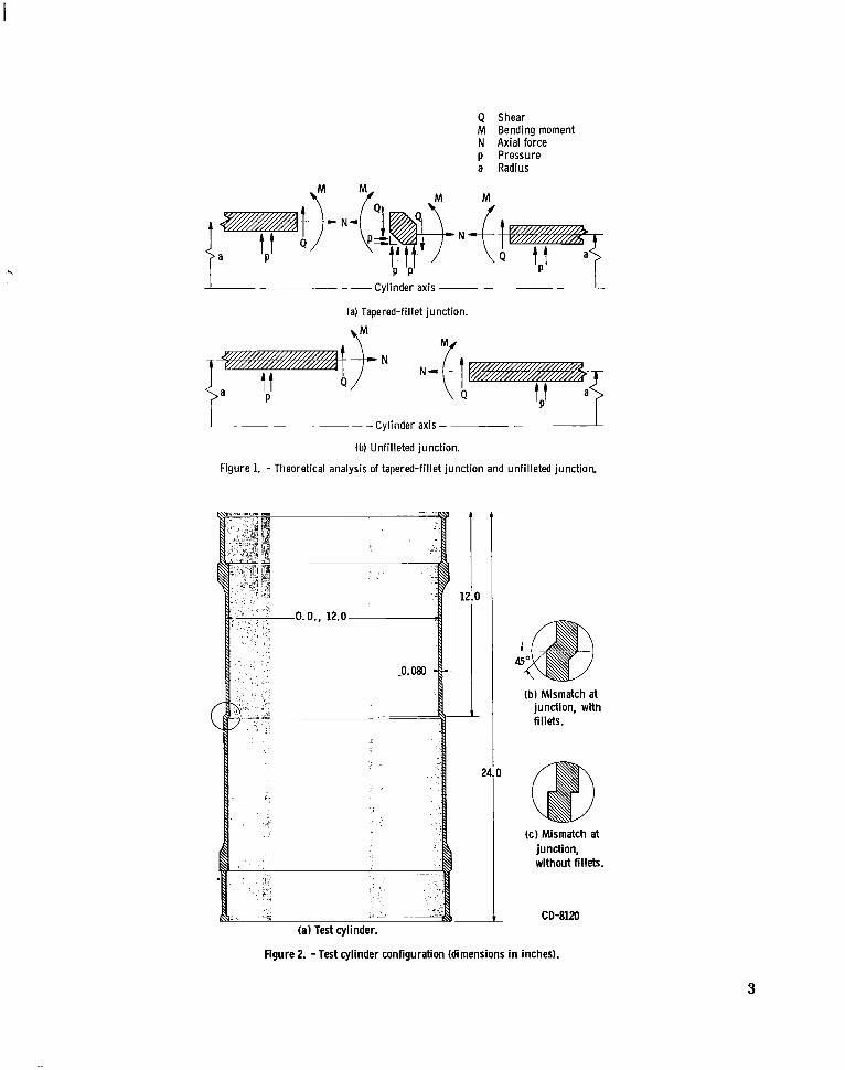
Q Shear M Bending moment N Axial force p Pressure a Radius
Cylinder axis ~ - ~ - 1 -~
(a) Tapered-fillet junction.
I Cylinder axis -
(b) Unfilleted junction.
Figure 1. - Theoretical analysis of tapered-fillet junction and unfilleted junction.
(bl Mismatch at junction, with fillets.
( c l Mismatch at junction, without fillets.
CD-8120 (a) Test cylinder.
Figure 2. -Test cylinder configuration (dimensions in inches).
3
discontinuity. This stress distribution may be added to the membrane stresses for the final solution.
structure is considered as separated into two cylinders, as shown in figure l(b). Stress distribution is determined essentially as described for the filleted mismatch; absence of the ring segment permits a less complicated solution.
In the case of a cylindrical vessel with a circumferential mismatch and no fillets, the
APPARATUS AND PROCEDURE
Test Cylinders
The test cylinders were fabricated with a nominal ratio of radius to wall thickness of 75. Figure 2(a) shows the basic configuration of the cylinders used in the investiga- tion. Three cylinders were made with circumferential junctions with mismatches of 20, 60, and 100 percent, respectively, based on the radial difference between middle sur- faces compared to wall thickness, and the junctions were provided with 45' tapered fil- lets, as shown in figure 2(b). Values for percent of mismatch were selected arbitrarily to provide a range of mismatch and were not intended to be acceptable limits of e r ror in space-vehicle assembly. A fourth cylinder was provided with a 60-percent mismatch and minimum fillet radii at the junction, as shown in figure 2(c).
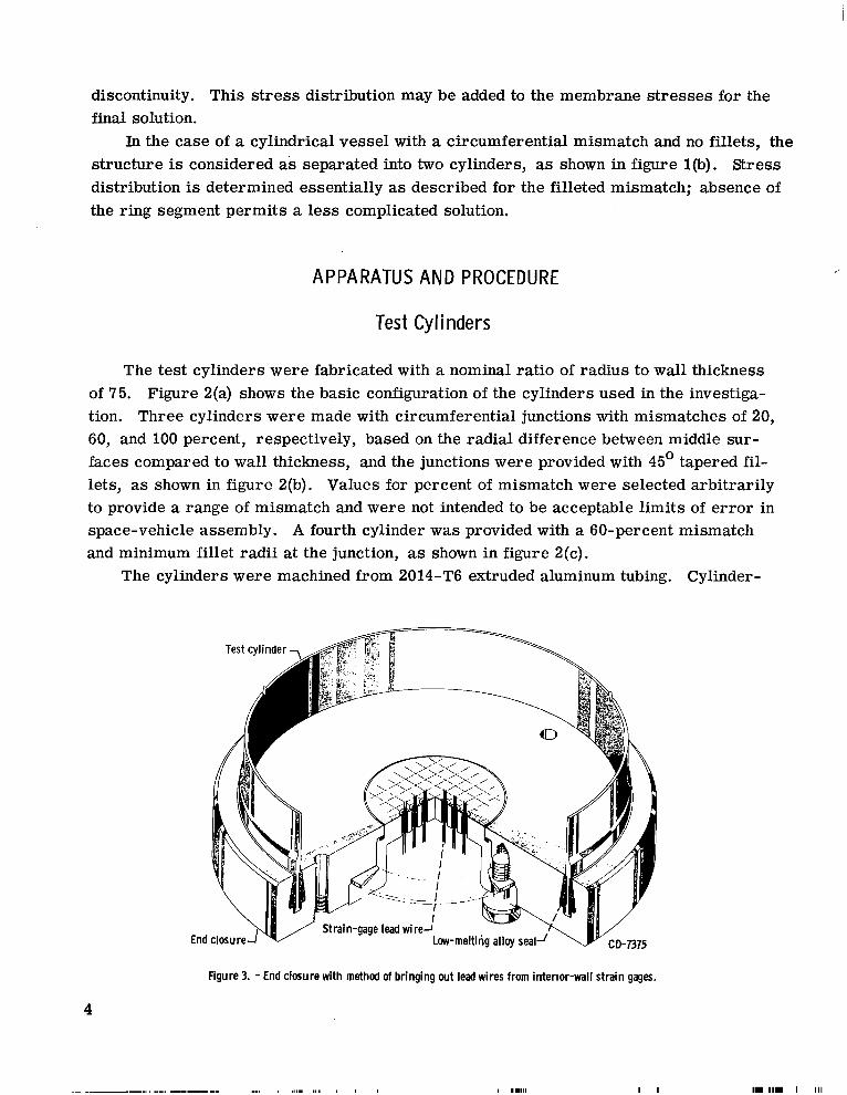
The cylinders were machined from 2014-T6 extruded aluminum tubing. Cylinder-
End
Test cylinder -, ~
Strain-gage lead wireJ Low-melting alloy sea
Figure 3. - End closure with method of bringing wt lead wires from interior-wall strain gages.
4
I I .I11 1 1 1 1 1 I 111
wall thickness was 0.080*0.001 inch; diameters were within *O. 002 of specified values, and out-of-roundness did not exceed 0.001 inch. End closures of the type shown in figure 3 were provided. Assembly and dis- assembly of these closures required that the parts be brought to the tem- perature required to liquefy the alloy that forms the seal (325' F).
- m c
E 0
z
.-
O L-
2 1 I
I Strai n-Gage Installation
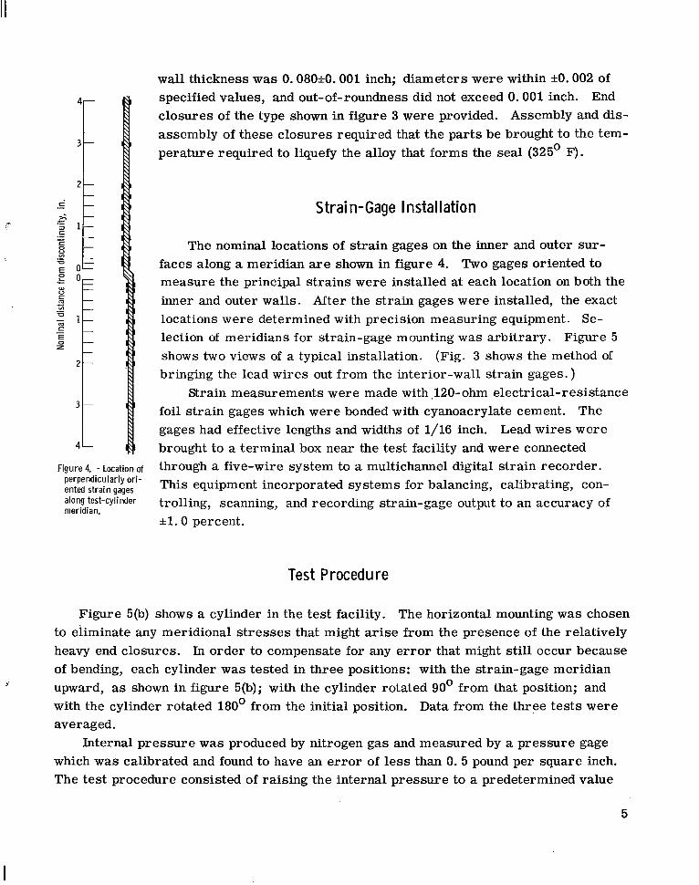
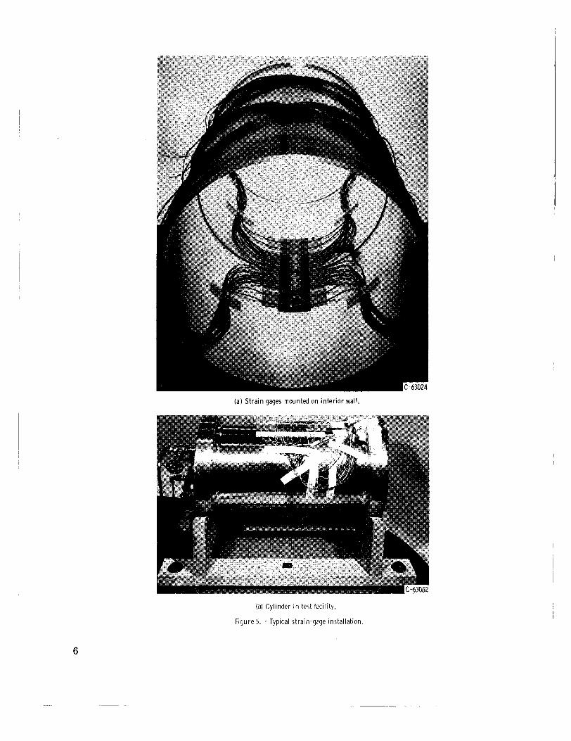
The nominal locations of strain gages on the inner and outer sur- faces along a meridian are shown in figure 4. Two gages oriented to measure the principal strains were installed at each location on both the inner and outer wal ls . After the strain gages were installed, the exact locations were determined with precision measuring equipment. Se- lection of meridians for strain-gage mounting was arbitrary. Figure 5 shows two views of a typical installation. (Fig. 3 shows the method of bringing the lead wires out from the interior-wall strain gages. )
Strain measurements were made with $120-ohm electrical-resistance foil strain gages which were bonded with cyanoacrylate cement. The gages had effective lengths and widths of 1/16 inch. brought to a terminal box near the test facility and were connected through a five-wire system to a multichannel digital strain recorder. This equipment incorporated systems for balancing, calibrating, con- trolling, scanning, and recording strain-gage output to an accuracy of *l. 0 percent.
Lead wires were 4 I[
Figure 4 - Location of perpendicularly ori- ented strain gages
test-cylinder meridian.
Test Procedure
Figure 5(b) shows a cylinder in the test facility. The horizontal mounting was chosen to eliminate any meridional s t resses that might arise from the presence of the relatively heavy end closures. In order to compensate for any error that might still occur because of bending, each cylinder was tested in three positions: with the strain-gage meridian upward, as shown in figure 5(b); with the cylinder rotated 90° from that position; and with the cylinder rotated 180' from the initial position. Data from the three tes ts were averaged.
which was calibrated and found to have an er ror of less than 0. 5 pound per square inch. The test procedure consisted of raising the internal pressure to a predetermined value
9
Internal pressure was produced by nitrogen gas and measured by a pressure gage
5
(a) Strain gages mounted on inter ior wall.
(b) Cylinder in test facility.
Figure 5. - Typical strain-gage installation.
6
and returning it to zero pressure according to a time schedule that provided sufficient in- tervals for stabilization of the strain gages. This basic cycle was repeated for progres- sively higher pressures until the maximum required pressure had been achieved. The purpose of making successive increases in pressure was to provide data for correction of any nonlinearity in strain-gage output. Data were recorded at pressures of 100, 110, 120, 130, 140, and 150 pounds per square inch, and duplicate tests were made at each of the three cylinder positions.
Reduction of Data
The computer program used to reduce the data read in the strain-gage outputs, cor- rected for zero drift, corrected any nonlinearity by using the method of least squares, averaged the strains, and converted strains to principal s t resses and effective s t resses (yield criterion based on distortion- energy theory) by using the following relations (with the material assumed to be isotropic):
Meridional stress
Cir cumf e r entia1 s t r e s s
1 - v'
Effective s t r e s s
where
u st ress , psi
E modulus of elasticity, psi
v Poisson's ratio, 1/3
E strain, in./in.
7
and the subscripts x, 8, and e denote meridional, circumferential, and effective stresses, respectively.
RESULTS AND DISCUSSION
The strain data were reduced to principal and effective s t r e s s values, as described in the section Reduction of Data, and these experimental results were compared with the s t ress distributions obtained by theoretical analysis. In order to provide a parameter useful in comparisons among the different cases tested, the stress values were divided by membrane s t ress computed on the basis of thin-wall theory, using an average radius for an individual cylinder.
Mismatch with Fi l lets
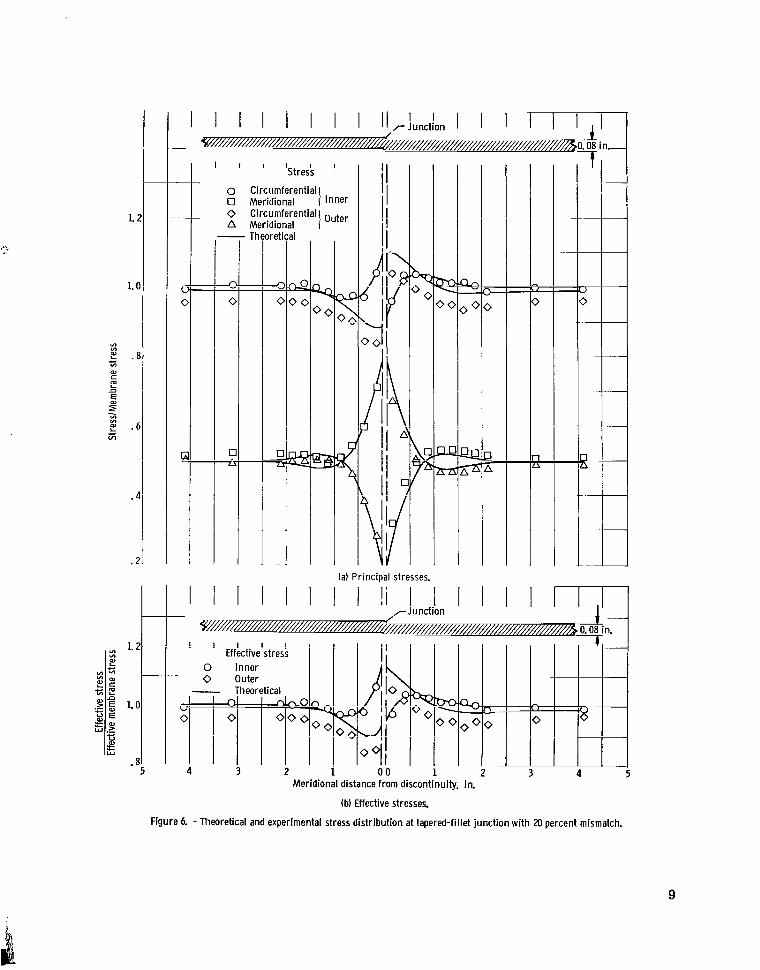
Comparisons are shown in figures 6, 7, and 8, for the tapered-fillet junctions with mismatches of 20, 60, and 100 percent, respectively. In general, there appeared to be good correlation.
s t resses determined by experiment were substantially in agreement with analytical val- ues, and approximately the same degree of correlation was established for the inner-wall circumferential stress distribution. The most marked disparity between experimental and analytical values was observed for outer-wall circumferential stresses, as will be discussed in the section Experimental Error. results closely followed the trends predicted by theory. This is shown more clearly by the comparison of effective stress distributions in figure 6(b). The inner-surface s t ress values obtained experimentally were nearly coincident with analytical curves of s t ress distribution, and the experimental stress points for the outer surface varied from the analytical curve by a fairly constant value.
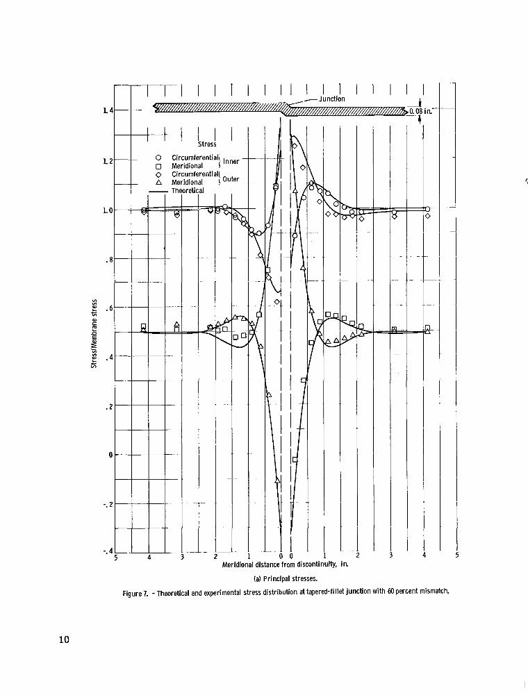
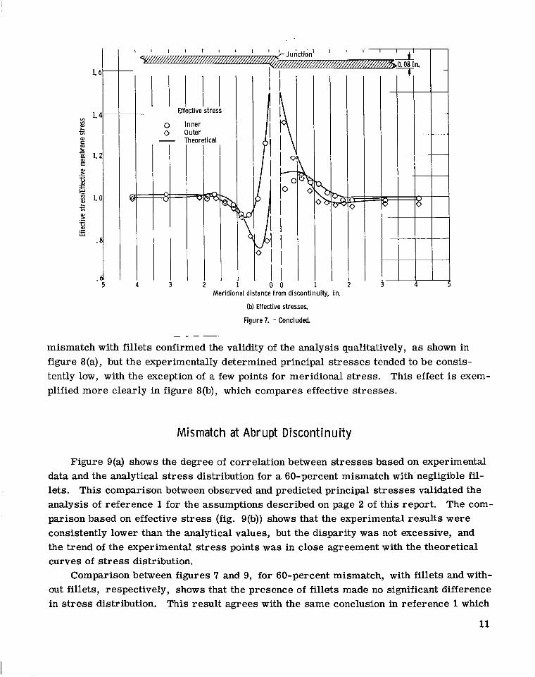
the analytical s t ress distribution for the 60-percent mismatch with fillets. In general, correlation was satisfactory, both quantitatively and qualitatively, although there was some disparity between the experimental values and the theoretical s t ress distribution for the inner-wall meridional and outer-wall circumferential stresses. The effect of this difference is shown in the comparison based on effective stress (fig. 7(b)). The test results tended to follow the theoretical curve for s t ress distribution, but considerable quantitative discrepancy occurred near the junction.
In the case of the 20-percent mismatch with fillets (fig. 6(a)), the meridional
On a qualitative basis the experimental
Figure 7(a) presents the principal s t resses obtained from strain data compared with
Comparison between test results and theoretical curves for the case of 100-percent
8
I l l 1 St re is '
0 Circumferential 0 Meridional } inner 0 Circumferential} Outer A Meridional
(a) Principal stresses.
Meridional distance from discontinuity, in.
(b) Effective stresses.
Figure 6 - Theoretical and experimental stress distribution at tapered-fillet junction with 20 percent mismatch.
9
- + Stress
0 Circumferential} - 0 Meridional 0 Circumferential A Meridional /Outer -
4
v- PI I 1 I
11 I I
.. 0 0
Meridional distance from discontinuity, in.
(a) Principal stresses.
Figure 7. - Theoretical and experimental stress distribution at tapered-fillet junction with M) percent mismatch.
10
1.
L VI * I VI
al c
t
E n
E E 1.
al >
u al
.- c
c i5 3 1. E
5
- c * al > .- r: W
I I I I I Effective stress
0 Inner o Outer
Theoretical m 3 2
Y <
I 02
1 Meridional distance from discontinuity, in.
(b) Effective stresses.
Figure 7. - Concluded
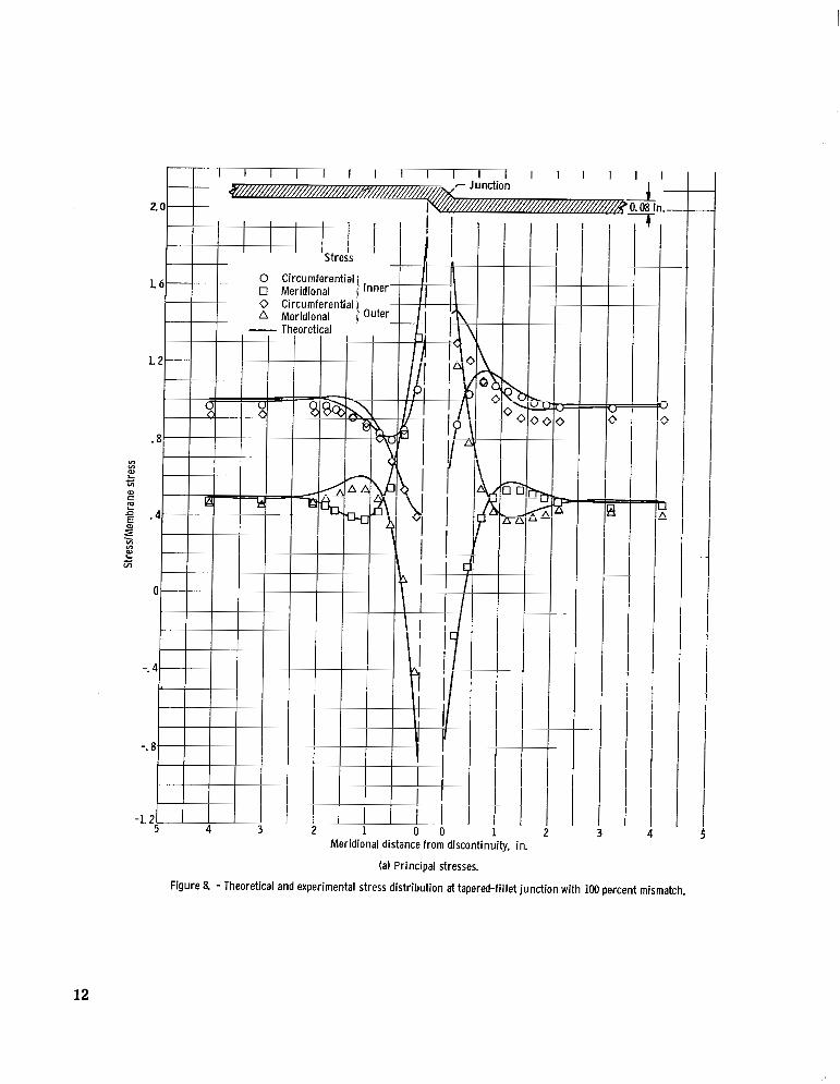
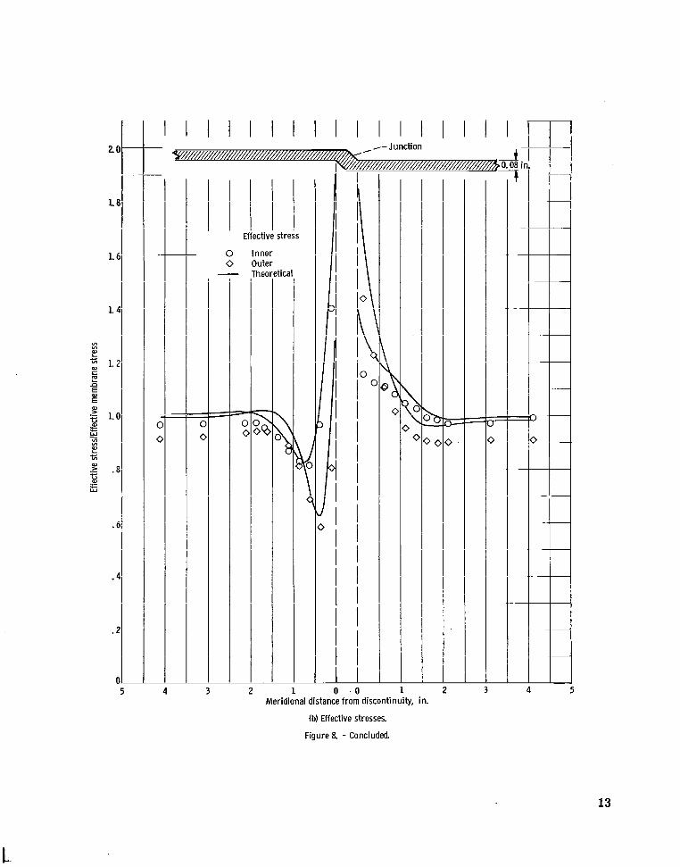
mismatch with fillets confirmed the validity of the analysis qualitatively, as shown in figure 8(a), but the experimentally determined principal s t resses tended to be consis- tently low, with the exception of a few points for meridional s t ress . plified more clearly in figure 8(b), which compares effective stresses.
This effect is exem-
Mismatch at Abrupt Discontinuity
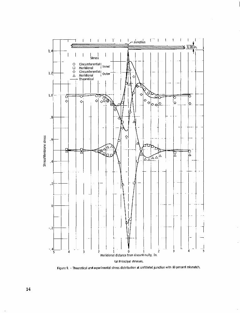
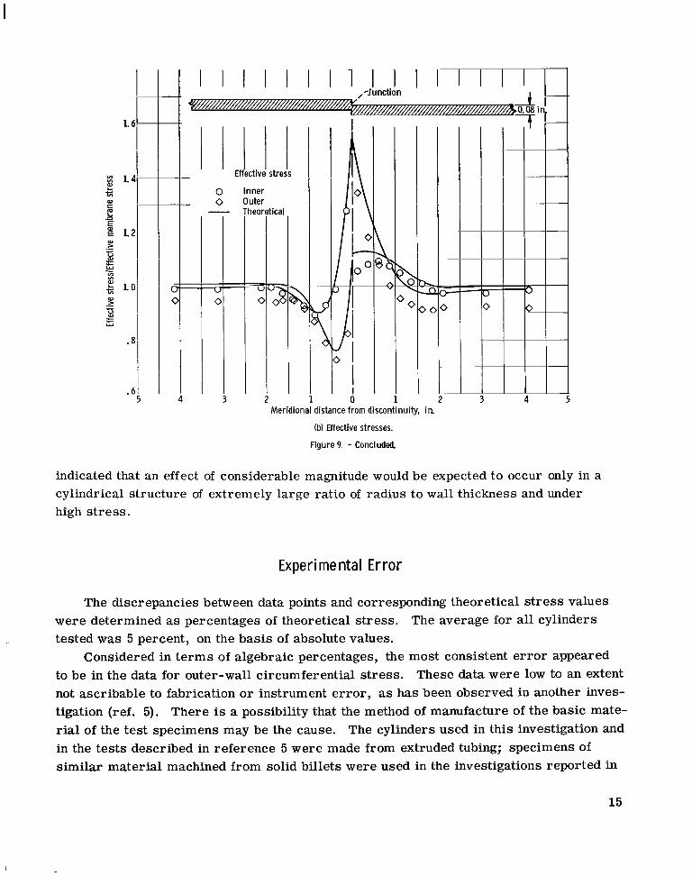
Figure 9(a) shows the degree of correlation between s t resses based on experimental data and the analytical s t ress distribution for a 60-percent mismatch with'negligible f i l - lets. This comparison between observed and predicted principal s t resses validated the analysis of reference 1 for the assumptions described on page 2 of this report. The com- parison based on effective s t ress (fig. 9(b)) shows that the experimental results were consistently lower than the analytical values, but the disparity was not excessive, and the trend of the experimental stress points was in close agreement with the theoretical curves of stress distribution.
Comparison between figures 7 and 9, for 60-percent mismatch, with fillets and with- out fillets, respectively, shows that the presence of fillets made no significant difference in stress distribution. This result agrees with the same conclusion in reference 1 which
11
- 2.0 n.-
Meridional distance from discontinuity, in.
(a) Principal stresses.
Figure 8. - Theoretical and experimental stress distribution at tapered-fillet junction with 100 percent mismatch.
12
VI 111
E
E
c VI
m c
n
E m w .- H E ? - VI 111
c v1
al > 1-
H = w
I I I I I I I I I I I I I I I I I
4
I I I t I I
Effective stress
0 Inner 0 Out6
0
I
I I I
I i I I I i
i L
C
0 . o I
Meridional distance from discontinuity, in.
(b) Effective stresses.
Figure 8. - Concluded.
13
i I - - I I I i I
1 I I I I I I
Stress
1. 2 IT LO
.8
- 0 Circumferential 0 Meridional 1 Inner 0 circumferential! Outer- A Meridional
Th
7 C
4 -i --
1 I L
- 1
0 Meridional distance from discon
(a) Principal stresses.
2 iuity, in.
I
Figure 9. - Theoretical and experimental stress distribution at unfilleted junction with 60 percent mismatch.
14
Meridional distance from discontinuity, in.
(b) Effective stresses.
Figure 9. - Concluded
indicated that an effect of considerable magnitude would be expected to occur only in a cylindrical structure of extremely large ratio of radius to wall thickness and under high s t ress .
Experimental Error
The discrepancies between data points and corresponding theoretical s t ress values were determined as percentages of theoretical stress. The average for all cylinders tested was 5 percent, on the basis of absolute values.
to be in the data for outer-wall circumferential stress. These data were low to an extent not ascribable to fabrication or instrument error , as has been observed in another inves- tigation (ref. 5). There is a possibility that the method of manufacture of the basic mate- rial of the test specimens may be the cause. The cylinders used in this investigation and in the tests described in reference 5 were made from extruded tubing; specimens of similar material machined from solid billets were used in the investigations reported in
Considered in te rms of algebraic percentages, the most consistent e r ror appeared
15
references 6 and 7, and for these specimens the data were not characterized by low val- ues for outer-wall circumferential stress.
It should be pointed out, however, that the possible presence of orthotropic material properties does not provide an adequate reason for the discrepancy between experimental and theoretical outer-wall circumferential stresses. An examination of the equations for an orthotropic stress field indicated that the experimentally determined meridional s t resses also should have shown an appreciable effect, and this was not the case. No entirely satisfactory explanation can be advanced at the present time.
CONCLUDING REMARKS
The investigation included tests of three tapered-fillet junctions with mismatches of 20, 60, and 100 percent, respectively, and one abrupt junction with a 60-percent mis- match. The results of the experimental investigation substantiated the theoretical analy- sis of reference 1 for the stress distribution in the region of a circumferentially mis- matched junction between thin-walled cylinders under internal pressure.
Lewis Research Center, National Aeronautics and Space Administration,
Cleveland, Ohio, May 19, 1966, 124-11-06-01-22.
REFERENCES
1. Bizon, Peter T. : Elastic Stresses at a Mismatched Circumferential Joint in a Pres- surized Cylinder Including Thickness Changes and Meridional Load Coupling. NASA
TN D-3609, 1966.
2. Johns, Robert H. ; and Orange, Thomas W. : Theoretical Elastic Stress Distributions Arising from Discontinuities and Edge Loads in Several S%ell-Type Structures. NASA TR R-103, 1961.
3. Johns, Robert H. : Theoretical Elastic Mismatch Stresses. NASA TN D-3254, 1966.
4. Hetgnyi, M. : Beams on Elastic Foundation. Univ. of Mich. Press , 1964.
5. Morgan, William C. ; and Bizon, Peter T. : Experimental Investigation of Stress Dis- tributions Near Abrupt Change in Wall Thickness in Thin-Walled Pressurized Cylin- ders. NASA TN D-1200, 1962.
16
6. Morgan, William C. ; and Bizon, Peter T. : Experimental Evaluation of Theoretical Elastic Stress Distributions for Cylinder-to-Hemisphere and Cone-to- Sphere Junc- tions in Pressurized Shell Structures. NASA TN D-1565, 1963.
7. Johns, Robert H. ; Morgan, William C. ; and Spera, David A. : Theoretical and Exper- imental Analysis of Several Typical Junctions in Space Vehicle Structures. Appendix - Stress Analysis of Edge-Loaded Pressurized Cone. Preprint No. 2427-62, Am. Rocket Soc., Inc., 1962.
NASA-Langley, 1966 E-3019 17
“The aeronautical atid space activities of the United States shall be conducted so as to contribute . . . t o the expansion of human RzowI- edge of phenomena i n the atmosphere and spare. T h e Administration shall provide for the widest practicable and appropriate dissemination of information comerning its actiujties and the results tbereo f .”
-NATIONAL AERONAUTICS AND SPACE ACT OF 1958
NASA SCIENTIFIC AND TECHNICAL PUBLICATIONS
TECHNICAL REPORTS: important, complete, and a lasting contribution to existing knowledge.
TECHNICAL NOTES: of importance as a contribution to existing knowledge.
TECHNICAL MEMORANDUMS: Information receiving limited distri- bution because of preliminary data, security classification, or other reasons.
CONTRACTOR REPORTS: Technical information generated in con- nection with a NASA contract or grant and released under NASA auspices.
TECHNICAL TRANSLATIONS: Information published in a foreign language considered to merit NASA distribution in English.
TECHNICAL REPRINTS: Information derived from NASA activities and initially published in the form of journal articles.
SPECIAL PUBLICATIONS: Information derived from or of value to NASA activities but not necessarily reporting the results .of individual NASA-programmed scientific efforts. Publications include conference proceedings, monographs, data compilations, handbooks, sourcebooks, and special bibliographies.
Scientific and technical information considered
Information less broad in scope but nevertheless
Details on the availability o f these publications may be obtained from:
SCIENTIFIC AND TECHNICAL INFORMATION DIVISION
N AT1 0 NAL AERONAUTICS AND SPACE ADM I N ISTRATI 0 N
Washington, D.C. PO546
4