Embed Size (px)
Citation preview
I . I I
I I I
NASA TECHNICAL NOTE N A S
c i
A N ANALYTICAL EVALUATION OF THE DENTING OF AIRPLANE SURFACES BY HAIL
J+
by Robert G. Thomson dud Robert J. Huydzdk
LungZey Research Center LungZey Station, Humpton, Vu.
A TN D-5363 - - I_I
N A T I O N A L AERONAUTICS A N D SPACE A D M I N I S T R A T I O N W A S H I N G T O N , D . C . AUGUST 1 9 6 9
https://ntrs.nasa.gov/search.jsp?R=19690024042 2018-06-29T20:58:11+00:00Z
TECH LIBRARY KAFB, NM
Elastic deformations Th in sheets Dynamic Hailstone dents . . . ; ~ . . . . . . .
I111111 11111 lllll11111lllll11111 IIIII 1111 Ill
_ . . .
2. Government Accession No. I 1. Report No. NASA TN D-5363
4. T i t l e and Subt i t le
AN ANALYTICAL EVALUATION OF THE DENTING
OF AIRPLANE SURFACES BY HAIL
7. Author(s) Robert G. Thomson and Robert J. Hayduk
9 . Performing Orgonization Name and Address
NASA Langley Research Center
Langley Station
Hampton, Va. 23365
2. Sponsoring Agency Name ond Address
National Aeronautics and Space Administrat ion
Washington, O.C. 20546
15. Supplementary Notes
16. Abstract
3. Recipient 's Cotalog No.
5. Report Dote August 1969
6. Performing Orgonizotion Code
8. Performing Organization Report No. 1-6494 - .
0. Work Un i t No. 126-61-01-07-23
1. Contract or Grant No.
3. Type o f Report and Per iod Covered
Technical Note
14. Sponsoring Agency Code
Hailstone damage to a i rc ra f t i s exhibited as denting o r complete penetration. A n analytical evaluation of
such denting characterist ics of aircraft surfaces i s idealized by having a crushable spherical project i le impact
normal to a flat plate. Separate elastic and rigid-plastic andyses have been developed previously by us ing the
classical thin-plate bending approach. As applied in t h i s paper, t he elastic analysis determines the area of t he
sheet around the center of impact, wh ich has become plastic. The rigid-plastic analysis applied to t h i s central
plastic region determines the resul t ing permanent deformation (dent). Numerical resul ts are presented in
detail for t he permanent deformations of two specific sheet thicknesses.
17. Key Words Suggested by Author(s) Impulse loading Plastic deformations
18. Distr ibut ion Stdement
Unclassified - Unlimited
' .

AN ANALYTICAL EVALUATION OF THE DENTING
OF AIRPLANE SURFACES BY HAIL
By Robert G. Thomson and Robert J. Hayduk Langley Research Center
SUMMARY
Hailstone damage to airplanes is exhibited as denting or complete penetration. An analytical evaluation of such denting characteristics of airplane surfaces is idealized by having a crushable spherical projectile impact normal to a flat plate. Separate elastic and rigid-plastic analyses have been developed previously by using the classical thin- plate bending approach. As applied in this paper, the elastic analysis determines the a rea of the sheet around the center of impact, which has become plastic. The rigid- plastic analysis applied to this central plastic region determines the resulting permanent deformation (dent). Numerical results a r e presented in detail for the permanent defor- mations of two specific sheet thicknesses.
INTRODUCTION
Because of the high velocity of modern airplanes, the probability of surface damage caused by impact with hail, and possibly with other meteorological precipitants, has become a design consideration. Meteorological damage can take the form of either surface-material erosion, permanent deformation, or , i f the impact is severe enough, complete penetration of the surface. flight with photographic documentation of damage and an extensive bibliography is given in reference 1.
A summary of the effect of hail on airplanes in
No design criterion for hail encounter has been available to the aircraft designers until recently. In reference 2 a testing procedure is proposed to aid the designer in minimizing hail damage. The suggested approach is to test the affected structure by impacting it with representative samples of hail at various impact velocities to assure that no appreciable damage occurs. able, and the purpose of the present paper is to present an approximate analytical method to complement established laboratory testing procedures.
An analytical approach does not appear to be avail-
When a hailstone impacts the thin skin of an airplane, the resulting skin deforma- tions usually are plastic near the point of impact and elastic in the surrounding area. If

the impact is severe enough, both bending and membrane action a r e present in the skin. A rigorous, but difficult, approach to the problem would require a sophisticated, dynamic, elastic-plastic, large-deformation analysis. The analytical development in this paper, however, attempts to approximate the analysis of the problem to circumvent the difficul- t ies of the more rigorous approach.
In reference 3 an elastic analysis was developed by using the classical thin-plate bending approach for the impact of a spherical projectile on a thin infinite sheet. The results of that analysis determine the time-dependent expressions for the deformation, velocity, and moment distributions of the elastically deforming sheet. The elasticity assumptions, however, preclude any permanent -type deformations.
The rigid-plastic bending response of a finite circular sheet subjected to a trans- verse impulse loading has also been investigated. sis considers the entire finite sheet as plastic, and when deformations occur, the whole sheet experiences a permanent type of deformation. impact, if the extent of the plastic a r ea around the center of impact is knowrl, a rigid- plastic analysis can be used to predict the permanent-deformation characteristics (denting) of this region.
(See ref. 4.) The rigid-plastic analy-
Therefore, in regard to hailstone
In the present paper the elastic analysis of reference 3 is used to determine the radial and circumferential bending-moment distributions in an infinite elastic sheet impacted by a crushable spherical projectile. herein for a simply supported finite circular sheet impacted by a crushable spherical pro-
A rigid-plastic analysis is also developed
jectile, and the resulting permanent deformation is found. initial conditions on loading: assumed to impose an initial, instantaneous, finite velocity distribution over the region of impact, the rest of the plate being at rest . In both analyses the circumferential and radial moments a r e at a maximum at the center of the impact and decrease monotonically with increasing radius. For the infinite elastic sheet the bending moments around the center of impact a r e shown to exceed the dynamic elastic yield-moment resultant Mo.
The two analyses have identical a crushable spherical projectile in which the projectile is
In the present approach the simply supported, rigid-plastic boundary conditions on the radial and circumferential bending moments of the plastic analysis a r e matched with those of the elastic analysis at some radius near the center of impact called the plastic radius. The rigid-plastic analysis, using this plastic radius as the radius of the finite circular sheet, is then to be used to determine the permanent deformations. contention of the present paper is that sufficiently accurate results may be obtained when only the boundary conditions on the bending moments a r e satisfied between the elastic and plastic analyses in determining the plastic radius.-
The principal
-.-_ .. ... .
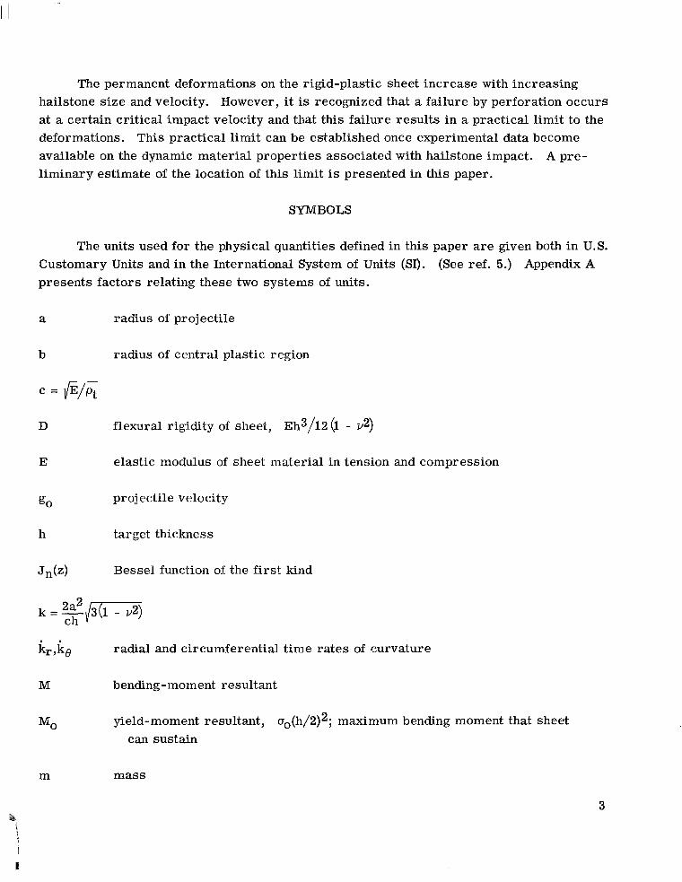
The permanent deformations on the rigid-plastic sheet increase with increasing hailstone size and velocity. However, it is recognized that a failure by perforation occurs at a certain critical impact velocity and that this failure results in a practical limit to the deformations. This practical lirriit can be established once experimental data become available on the dynamic material properties associated with hailstone impact. A pre- liminary estimate of the 1ocati.m of this limit is presented in this paper.
SYMBOLS
The units used for the physical quantities defined in this paper a r e given both in U.S. Customary Units and in the International System of Units (SI). presents factors rel.atiiig these two systems of units.
(See ref. 5.) Appendix A
a radius of projectile
b radius of central plastic region
c = f i
D flexural rigidity of sheet, ~ h 3 / 1 2 (I - v2)
E elastic modulus of sheet material in tension and compression
g0 projectile velocity
h target thickness
Jn(z) Bessel function of the first kind
kr,ko radial and circumferential time rates of curvature
M bending-moment resultant
MO yield-moment resultant, ~ ~ ( h / 2 ) ~ ; maximum bending moment that sheet can sustain
m mass
3
I
I

P Hankel transform parameter
Qr transverse shear - s t ress resultant
q impulse loading
r,e,z
t time
t*
t 1
radial, Circumferential, and transverse coordinates, respectively (see fig. 1)
time of cessation of all sheet motion after impact
time at which hinge-circle radius has decreased to zero
vo =
2a Pp h Pt go --
W
6 permanent center deflection, w(O,t*)
c
7 = r/a
P
sheet deflection in transverse direction (z-direction)
radius of hinge circle separating regimes A and AI3
V
5 = r/b
P
OO
mass per unit a rea of sheet, pth
Poisson's ratio
mass density
yield s t r e s s in simple tension o r compression (assumed to be identical in magnitude)
or 3 06 principal radial and circumferential s t resses , respectively
4
T = t/k
momentum constant (see eq. (7))
Subscripts:
c r critical
11 indicates order of Bessel function
P projectile
r radial
t target
e circumfer entia1
A dot over a symbol indicates partial differentiation with respect to time t. An asterisk denotes time at which the entire sheet comes to rest .
MATHEMATICAL ANALYSES
Determination of Initial Velocity Distribution
Lj.near, small-deflection plate theory was used in reference 3 to study the response of an infinite elastic sheet subjected to an axisymmetric impulse. The analysis assumed that the momentum exchange was the primary loading mechanism, that the exchange was instantaneous, and that the mass of the projectile was negligible after impact compared with the mass of the sheet. The three specific projectile shapes studied in reference 3 were cone, sphere, and cylinder. Reference will be made in this paper to the solution for the spherical projectile only, and the momentum distribution shown in figure 1 is derived from this shape.
The assumed instantmeous momentum exchange between projectile and sheet yields In an initial sheet velocity over the centrally impacted area, but no initial displacement.
the present analysis the mass of the projectile after impact is not neglected as in refer- ence 3. The momentum balance for a completely inelastic impact is
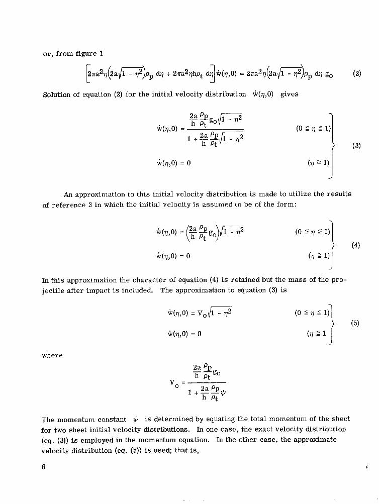
or, from figure 1
[ zKa2q(2a l / ' s )pp dq + 2aa2qhpt dq 1 ~ ( q , O ) = 2na2q(2a{G)pp dq go (2)
Solution of equation (2) for the initial velocity distribution w(q ,O) gives
W(q,O) = 0
An approximation to this initial velocity distribution is made to utilize the results of reference 3 in which the initial velocity is assumed to be of the form:
W(V,O) = - -go \I1 - 773, (E; ) -- W(q,O) = 0
(0 5 q i 1) 1 In this approximation the character of equation (4) is retained but the mass of the pro-
W(7,O) = v o / s
W(q,O) = 0
where
jectile after impact is included. The approximation to equation (3) is
(0 5 q 5 1)
(q 2 1
vo = 2a Pp 1 + - - * h Pt
The momentum constant is determined by equating the total m t for two sheet initial velocity distributions. In one case, the exact velocity distribution (eq. (3)) is employed in the momentum equation. In the other case, the approximate velocity distribution (eq. (5)) is used; that is,
6
mentum of the she

I
, . I ,
J~ 1 +--/- 2a PP Jo 1+2"%* h pt h Pt
and the momentum constant * becomes
The values of * used in the specific calculations in this paper are presented in table I along with the target (2024-T4 aluminum) and projectile material (ice) properties. comparison of the exact initial velocity distribution (eq. (3)) with the approximate initial velocity distribution (eq. (5)) is shown in figure 2 for a 0.25-inch-radius (0.64-cm) hail- stone impacting a 0.063-inch-thick (0.160-cm) plate (* = 0.71).
A
Determination of Moments in the Elastic Region
The boundary conditions of zero deflection, slope, and shear per unit length at infinity a d of zero slope and finite shear a t the origin were assumed in reference 3 i n order to obtain a solution in single integral form for the deflection of the dynamically deforming plate. The deflection (eq. (31) of ref. 3) can be written as
where in the present paper - 2a $go will be replaced by Vo. The expressions for the
radial and circumferential moments from elasticity theory are , respectively, h Pt
The radial and circumferential moments for can be written in the form (see appendix B):
v = 1/3 (eqs. (8), (9), and (10) combined)
*-
I 7
J
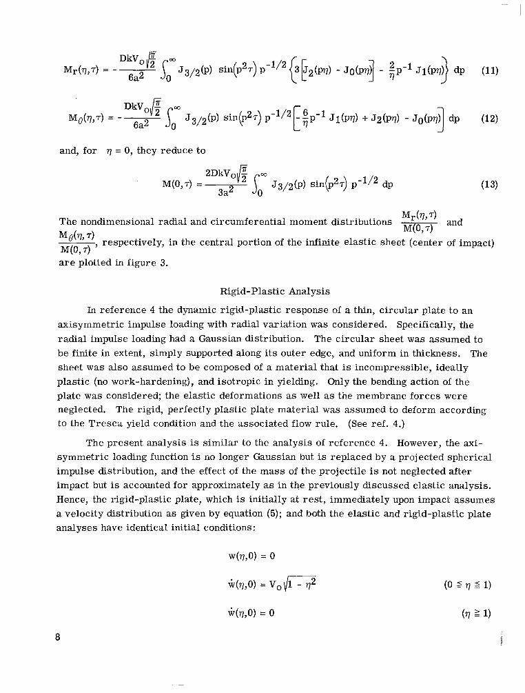
and, for q = 0, they reduce to
Mr(q,T) and M(0, 7)
The nondimensional radial and circumferential moment distributions
Mg(q'7), respectively, in the central portion of the infinite elastic sheet (center of impact)
a r e plotted in figure 3. M(0, 7)
Rigid-Plastic Analysis
In reference 4 the dynamic rigid-plastic response of a thin, circular plate to an axisymmetric impulse loading with radial variation was considered. Specifically, the radial impulse loading had a Gaussian distribution. be finite in extent, simply supported along its outer edge, and uniform in thickness. sheet was also assumed to be composed of a material that is incompressible, ideally plastic (no work-hardening), and isotropic in yielding. Only the bending action of the plate was considered; the elastic deformations as well as the membrane forces were neglected. The rigid, perfectly plastic plate material was assumed to deform according to the Tresca yield condition and the associated flow rule.
The circular sheet was assumed to The
(See ref. 4.)
The present analysis is similar to the analysis of reference 4 . However, the axi- symmetric loading function is no longer Gaussian but is replaced by a projected spherical impulse distribution, and the effect of the mass of the projectile is not neglected after impact but is accounted for approximately as in the previously discussed elastic analysis. Hence, the rigid-plastic plate, which is initially at rest, immediately upon impact assumes a velocity distribution as given by equation (5); and both the elastic and rigid-plastic plate analyses have identical initial conditions:
~ ( q , O ) = v o \ / i T i
W(q,O) = 0
8
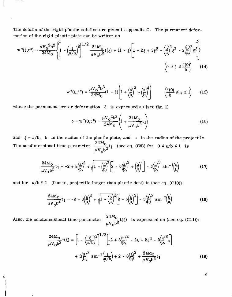
The details of the rigid-plastic solution a r e given in appendix C. mation of the rigid-plastic plate can be written as
The permanent defor-
where the permanent center deformation 6 is expressed as (see fig. 1)
and 5 = r/b, b is the radius of the plastic plate, and a is the radius of the projectile. - - 24M0
The nondimensional time parameter - t i (see eq. (C9)) for 0 5 a/b 2 1 is PVOb2
and for a/b 2 1 (that is, projectile larger than plastic dent) is (see eq. (C10))
24M0 Also, the nondimensional time parameter - t(5) is expressed as (see eq. (Cll)):
PVOb2
24M0 t(5) = [1 - ( & - r n [ 2 + 8($ - 25 + 2 t 2 - 3(tr5] PVOb2
+ 3($r sin-l(&) + 2 - 8 ( i r + - 24Mo pVob2 t1 (19)
9

.-
RESULTS AND DISCUSSION
Determination of Radius of Plastic Center
The simple-support boundary conditions of the rigid-plastic sheet, according to
plasticity theory (see appendix C), a r e that the radial moment M r equal zero and the circumferential moment Me equal Mo. Hence, the particular radial location b/a of the central plastic portion of the infinite elastic sheet was taken to be at the radial loca- tion where Mr = 0; this radial location changes with time. For different specific t imes the value of the circumferential moment Me at the radial location where M r = 0 will possess values that range from above to below the yield moment Mo (assuming that the sheet and hailstone properties remairi constant). When Me = Mo (with M r = 0), and only then, a r e the boundary conditions met for the simply supported plastic sheet; and it follows that this radius is the only radius of plastic yielding on the elastic sheet at which the boundary conditions a r e satisfied.
Typical (T = 1.5) radial (eq. (If)) and circumferential (eq. (12)) moment distribu- tions in the central portion of the infinite elastic sheet a r e plotted in figure 3. mum (and only) radius of the rigid-plastic region for a particular hailstone-sheet combi- nation is determined inversely by matching the rigid-plastic boundary conditions at a particular radius of the infinite elastic sheet. For example, in figure 3 b/a is chosen to be at the radial location q = 2.74 where M r = 0; the value of Me at q = 2.74 depends on the sheet and hailstone properties. I3 the sheet and hailstone properties a r e then selected so that Mo equals Mo, the yield moment, then the radius of the rigid- plastic sheet b/a equals 2.74 for this particular hailstone-sheet combination. Hence, any elastic moment distribution specifies the radius of a rigid-plastic sheet for a particu- lar hailstone diameter, plate thickness, and material when the hailstone velocity is selected to make the elastic circumferential moment Me (eq. (12)) equal to the yield moment Mo.
The maxi-
By calculating various moment distributions at a number of specific times, such as the one shown in figure 3, and applying the criterion for determining the maximum radius of plastic yielding (shown as the dashed line in fig. 31, a relationship between b/a and the initial projectile velocity can be established. Such a relationship is shown plotted in figure 4 for three different hailstones of 0.50-, 0.25-, and 0.125-inch radius (1.27-, 0.64-, and 0.32-cm). In figure 4 two typical aircraft skin thicknesses were chosen as target- plate thicknesses: 0.04 inch (0.10 cm), shown as the solid line, and 0.053 inch (0.160 cm), shown as the dashed line, respectively. The nondimensional plastic radius is shown in figure 4 to increase, for a particular velocity, as either the target thickness decreases and/or the projectile radius increases. Also, the plastic radius increases as the projec- tile velocity increases, as is expected.
10 I
At extremely small values of T (that is, T S 0.2) corresponding to values of b/a > 1, it should be noted, however, that an anomaly occurs in the moment distributions. Since it is known that classical plate theory predicts a spurious response at all points of a plate immediately after the application of a sharp impulse (ref. 6), the anomaly in the moment distributions is felt to be mathematical rather than physical. to distort the smooth monotonically decreasing form of the moment distributions as pre- sented in figure 3 and also the computed values of the plastic radius as shown in fig- ure 4. The computed values of the plastic radius begin to oscillate as b/a decreases below 0.5, and the curves presented in figure 4 have been faired between b/a = 0.5 and b/a = 0. The value of the projectile velocity at b/a = 0 can be easily (and accurately) determined by setting M ( ~ , T ) in equation (13) equal to Mo. Fortunately, this oscilla- tion in the computed values of b/a occurs in the region where the plastic dent has a '
smaller radius than the impacting hailstone and generally is of less interest than in the region where b/a > 1.
The anomaly tends
Determination of Permanent Center Deformation
The radius b, which is the maximum radius of plastic yielding from the elastic analysis, is now to be used as the finite radius of the rigid-plastic plate. tion (16) and the appropriate values of a, b, h, Mo, p, and others (see table I) for target and projectile material properties, the permanent center deflection 6 of the plastically deformed plate is determined. In figure 5, a logarithmic plot of the permanent center deformation as a function of projectile velocity is shown for three different hail- stones of 0.50-, 0.25-, and 0.125-inch radius (1.27-, 0.64-, and 0.32-cm) and with a target-sheet thickness of 0.063 inch (0.160 cm). The permanent center deformation is seen to approach a linear asymptote (shown as a dashed line) as the projectile velocity increases for the three sizes of hailstones. This linear asymptote has a constant slope of 2.85. tile size, probably because of the thinness of the target sheet relative to the mass of the hail st ones.
By use of equa-
The permanent center deformation is also shown to be very sensitive to projec-
In figure 6 the shape of the permanent deformation is plotted (eqs. (14) and (15)) for three specific projectile impact velocities of the 0.50-inch-radius (1.27-cm) hailstone. The projectile velocities a r e 330, 500, and 1100 ft/sec (0.10, 0.15, and 0.34 km/s) and show a progression from a shallow, circular, dish-shaped dent to a deep conical cavity. Thus, the shape of the dent, as well as the center deformation, changes as the projectile velocity is varied. The limited damage information available (ref. 1) indicates that the indentation predictions of the analysis a r e reasonable; however, adequate data for com- parison a r e not available.
11

I, I I I. I, I I I. 1.11.. ,.I, , . , .-.-
In figure 7, a logarithmic plot of the permanent center deformation as a function of projectile velocity is shown for hailstones of 0.50-, 0.25-, and 0.125-inch radius (1.27-, 0.64-, and 0.32-cm) but for a target-sheet thickness of 0.04 inch (0.10 cm). The perma- nent center deformation is again seen to approach a linear asymptote as the projectile velocity increases, in fact, the same asymptote as in figure 5. From the results given in figures 5 and 7 it is apparent that the permanent center deformation, in the high velocity
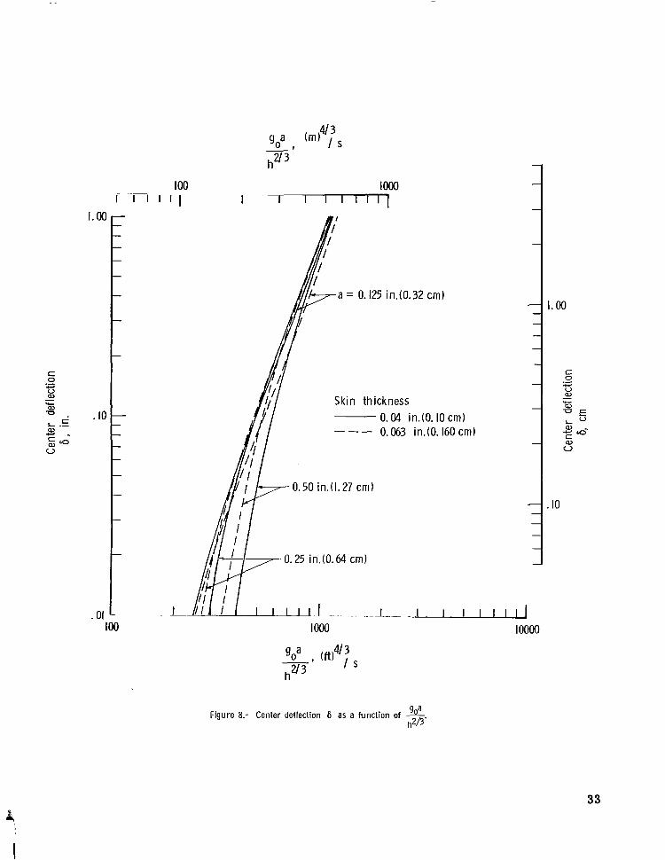
range, is a function of the projectile velocity go raised to the 2.85 power. In an attempt to show the six curves given in figures 5 and 7 on a single curve, the permanent center deformation is plotted as a function of gOa/h2l3 in figure 8 to a logarithmic scale. The curves in figure 8 show a general tendency toward a common linear asymptote in the high velocity range, but some spread does exist among the curves. This spread can be attrib- uted, in part, to the choice of the abscissa parameter gOa/h2l3.
Critical Impact Velocity
The critical impact velocity is defined as the minimum impact velocity for a given sheet and projectile combination that barely allows the projectile to perforate the sheet. An analytical expression for the critical impact velocity of a thin sheet impacted by a spherical projectile is presented in reference 7. of the sheet by assuming a failure criterion based on a maximum fracture s t ress . critical impact velocity of a thin visco-plastic sheet impacted by a cylindrical projectile was studied in reference 8. By comparing the results presented in references 7 to 10, it can be shown that the relation between the critical sheet thickness and the critical impact velocity is linear, as is reported in both the elastic and visco-plastic analyses. The fol- lowing analytical relationship (ref. 7) is felt to be a reasonable statement of proportion- ality to determine the critical sheet thickness hcr for thin sheets impacted by spherical projectiles:
It was derived from the elastic response The
A proportionality constant, which would be a function
(20)
of the sheet material properties, can be determined once meaningful experimental data on the dynamic material properties of thin sheets impacted with hailstones become available. Limiting ballistic envelopes are plotted in figures 5 and 7 as the long-short, dashed curves. envelope is presumed to be known at present; its location has been estimated and is sub- ject to change.
The shape of this limiting
12

CONCLUDING REMARKS
The present analysis, although not an exact elastic-plastic treatment, has combined separate elastic and rigid-plastic analyses to study hail damage to airplane surfaces. The results of this analysis indicate that thin structural members, such as the large skin a reas of airplanes a r e quite susceptible to denting by hailstones. greater the damage, of course, but the analysis also indicates great sensitivity to impact velocity as the hailstone size increases. In fact, the permanent center of deformation of an impacted skin has been shown to approach a function of the impact velocity to the 2.85 power for center deformations of 0.10 inch (0.25 cm) o r over.
The larger the hailstone the
The analytical results presented herein must await experimental verification. Although the magnitudes of the permanent deformations may be found to be in need of adjustment because of the neglect of membrane action and the numerous simplifying assumptions of the present analysis, it is hoped that the parametric study made herein and especially the impact-velocity dependency uncovered may prove to be useful. It is realized also that the results presented a re for normal impact onto flat sheets, and that some of the most severe hail damage to aircraft occurs at the leading edge of wing and tail assemblies, which a r e highly curved. nected with curvature of the sheet need to be evaluated. It is suggested that for oblique impact the normal component of the impact be considered as a first approximation.
The strengthening and geometric factors con-
Perforation of the airplane skin occurs at some critical impact velocity, but the pre- diction by analysis of the magnitude of this impact velocity awaits experimental determina- tion of some material properties at impact conditions.
Langley Research Center, National Aeronautics and Space Administration,
Langley Station, Hampton, Va., May 15, 1969, 126-61-01-07-23.
13
i

I I l11111l11111111111111l1Il I l l IIIII I Ill I II I I
APPENDIX A
CONVERSION OF U.S. CUSTOMARY UNITS TO SI UNITS
The International System of Units (SI) was adopted by the Eleventh General Confer- ence on Weights and Measures, Paris, October 1960, in Resolution No. 12 (ref. 5). Con- version factors for the units used herein a r e given in the following table:
Physical quantity
Length . . . . . . Density . . . . . . Stress . . . . . . Velocity. . . . . .
U.S. customary unit
in. lbm/ft3 ps i (lbf/in2) ft/sec
Conversion factor
(4 0.0254 16.02 6.895 X 10³ 0.3048 ~
SI unit
meters (m) kilograms per cubic meter (kg/m3) newtons per square meter (N/m2) meters per second (m/s)
aMultiply value given in U.S. customary unit by conversion factor to obtain equiva- lent value in SI unit.
Prefixes to indicate multiple of units a r e as follows:
Prefix Multiple
centi (c) kilo (k)
14
APPENDIX B
MOMENT EXPRESSIONS FOR CRUSHABLE SPHERICAL PROJECTILE
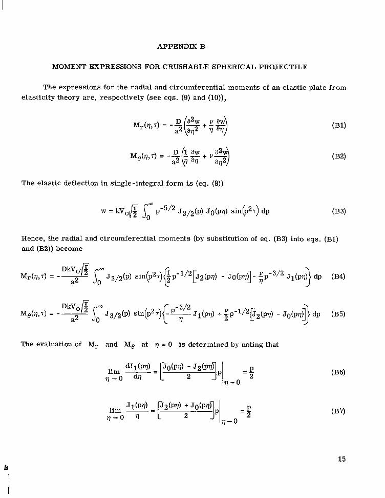
The expressions for the radial and circumferential moments of an elastic plate from elasticity theory are, respectively (see eqs. (9) and (lo)),
The elastic deflection in single-integral form is (eq. (8))
Hence, the radial and circumferential moments (by substitution of eq. (B3) into eqs. (Bl) and (B2)) become
The evaluation of Mr and Me at q = 0 is determined by noting that
15
APPENDIX B
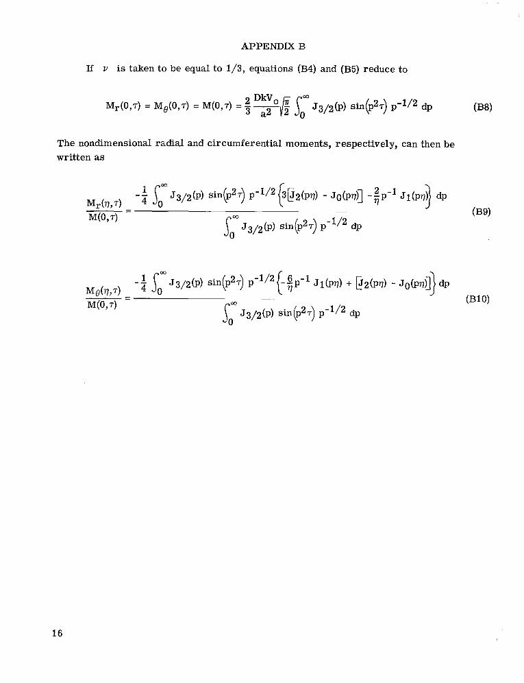
If v is taken to be equal to 1/3, equations (B4) and (B5) reduce to
The nondimensional radial and circumferential moments, respectively, can then be written as
16

APPENDIX C
RIGID-PLASTIC SOLUTION FOR SPHERICAL PROJECTILE IMPACT
The analytical derivation of the deflection of the plastically deforming, simply sup- ported circular plate presented in this appendix is similar in approach to existing dynamic rigid-plastic solutions. The development of the governing equations closely parallels that of reference 4, except for a change in the functional form of the initial velocity distribu- tion across the plate. (For a more complete discussion of rigid-plastic theory of plas- ticity, utilizing the Tresca yield condition and the associated flow rule, the reader is referred to reference 4.) The development of the deflection expressions for the plasti- cally deforming plate is divided in this appendix into two sections. sents the solution for the motion of the plate when the plate is divided into two distinct plasticity regimes, separated by a hinge circle, up to the time of the disappearance of this hinge circle. it continues to deform, up to the time of cessation of all motion. brief and concise as possible because the analytical development is similar to that pre- sented in reference 4, and a more complete treatment is not deemed to be necessary.
The first section pre-
The second section contains the solution for the motion of the plate as Both sections will be as
Solution With Hinge Circle of Finite Radius
The rigid-plastic plate, which is initially at rest , immediately upon impact assumes an axisymmetric velocity distribution in the central portion of the plastic plate (designated regime A of the Tresca yield hexagon in fig. 9) of the form
where the magnitude of the velocity Vo is a function of the projectile and plate param- e te rs (see eq. (5)),
and c(t) is the radius of the hinge circle separating regimes A and AB, and 5 = r/b.
In the surrounding annulus of the remaining portion of the plastic plate (designated regime AB of the Tresca yield hexagon in fig. 9), the proper velocity distribution according to the dictates of rigid-plastic theory (see ref. 4) is linear in 5, continuous
17
APPENDIX C
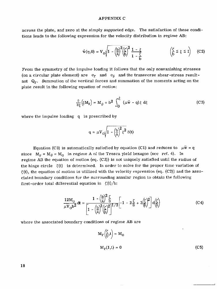
across the plate, and zero at the simply supported edge. tions leads to the following expression for the velocity distribution in regime AB:
The satisfaction of these condi-
From the symmetry of the impulse loading it follows that the only nonvanishing s t resses (on a circular plate element) a r e O r and 06 and the transverse shear-s t ress result- ant Qr. Summation of the vertical forces and summation of the moments acting on the plate result in the following equation of motion:
where the impulse loading q is prescribed by
Equation (C3) is automatically satisfied by equation (Cl) and reduces to ,uw = q since Mr = MQ = Mo in regime A of the Tresca yield hexagon (see ref. 4). regime AB the equation of motion (eq. (C3)) is not uniquely satisfied until the radius of the hinge circle c(t) is determined. c(t), the equation of motion is utilized with the velocity expression (eq. (C2)) and the asso- ciated boundary conditions for the surrounding annular region to obtain the following first-order total differential equation in <(t)/b:
In
In order to solve for the proper time variation of
where the associated boundary conditions of regime AB are
M (2 t) = Mo I- b’
Mr(17t) = 0
18
APPENDIX C
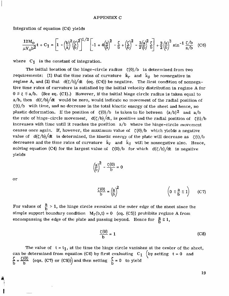
Integration of equation (C4) yields
where C1 is the constant of integration.
requirements: (1) that the time ra tes of curvature kr and k6 be nonnegative in regime A, and (2) that d(</b)/dt (eq. (C4)) be negative. The first condition of nonnega- tive time rates of curvature is satisfied by the initial velocity distribution in regime A for 0 5 t; S a/b. a/b, then d(</b)/dt would be zero, would indicate no movement of the radial position of <(t)/b with time, and no decrease in the total kinetic energy of the sheet and hence, no plastic deformation. If the position of <(O)/b is taken to lie between (a/b)2 and a/b the rate of hinge-circle movement, d(</b)/dt, is positive and the radial position of <(t)/b increases with time until it reaches the position a/b where the hinge-circle movement ceases once again. If, however, the maximum value of <(O)/b which yields a negative value of d(</b)/dt is determined, the kinetic energy of the plate will decrease as <(t)/b decreases and the time rates of curvature kr and ke will be nonnegative also. Hence, solving equation (C4) for the largest value of <(O)/b for which d(</b)/dt is negative yields
The initial location of the hinge-circle radius <(O)/b is determined from two
(See eq. (Cl).) However, if the initial hinge circle radius is taken equal to
o r
(0 5 ; 5 I) (C7)
For values of 5 > 1, the hinge circle remains at the outer edge of the sheet since the
simple support boundary condition Mr(b,t) = 0 encompassing the edge of the plate and passing beyond. Hence for a 2 1,
b (eq. (C5)) prohibits regime A from
b -
The value of t = t i , at the time the hinge circle vanishes at the center of the sheet, can be determined from equation (C6) by first evaluating C1 setting t = 0 and 1 = b b b
(eqs. (C7) o r (C8))) and then setting 2 = 0 to yield
19
I
APPENDIX C
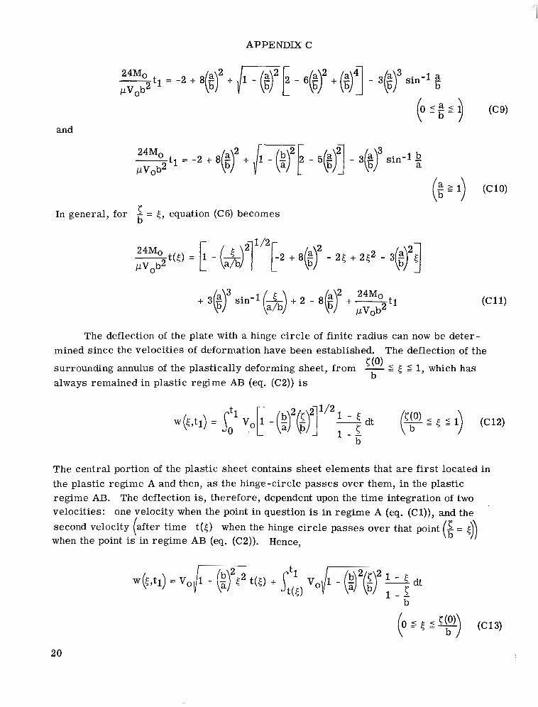
and
In general, for 2 = 5, equation (C6) becomes b
24Mo t(5) = 1 - (--&)2]1'2[2 + 8(f$ - 25 + 252 - 3 W0b2
The deflection of the plate with a hinge circle of finite radius can now be deter- mined since the velocities of deformation have been established.
surrounding annulus of the plastically deforming sheet, from b
always remained in plastic regime AB (eq. (C2)) is
The deflection of the
5 5 5 1, which has - - 5 (0)
The central portion of the plastic sheet contains sheet elements that are first located in the plastic regime A and then, as the hinge-circle passes over them, in the plastic regime AB. velocities:
when the point is in regime AB (eq. (C2)).
The deflection is, therefore, dependent upon the t ime integration of two one velocity when the point in question is in regime A (eq. (Cl)), and the
second velocity (after time t(5) when the hinge circle passes Over that point Hence,
1 - - b
20
I
APPENDIX C
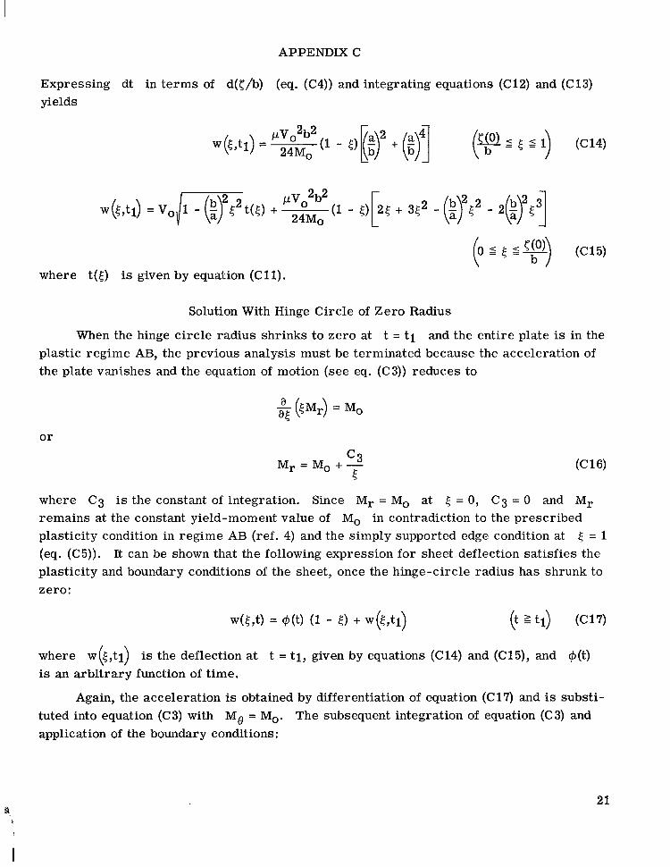
Expressing dt in te rms of d([/b) (eq. (C4)) and integrating equations (C12) and (C13) yields
where t(5) is given by equation (C11).
Solution With Hinge Circle of Zero Radius
When the hinge circle radius shrinks to zero at t = t i and the entire plate is in the plastic regime AB, the previous analysis must be terminated because the acceleration of the plate vanishes and the equation of motion (see eq. (C3)) reduces to
or
where C3 is the constant of integration. Since M r = Mo at 5 = 0, C3 = 0 and Mr
remains at the constant yield-moment value of Mo in contradiction to the prescribed plasticity condition in regime AB (ref. 4) and the simply supported edge condition at 5 = 1 (eq. (C5)). It can be shown that the following expression for sheet deflection satisfies the plasticity and boundary conditions of the sheet, once the hinge-circle radius has shrunk to zero:
where w(<,tl) is the deflection at t = t i , given by equations (C14) and (C15), and +(t) is an arbitrary function of time.
Again, the acceleration is obtained by differentiation of equation (C17) and is substi- tuted into equation (C3) with Mo = M,. The subsequent integration of equation (C3) and application of the boundary conditions:
21 L
P
I I I I I I I I ll111ll111111 IIIIII II I I1 II
APPENDIX C
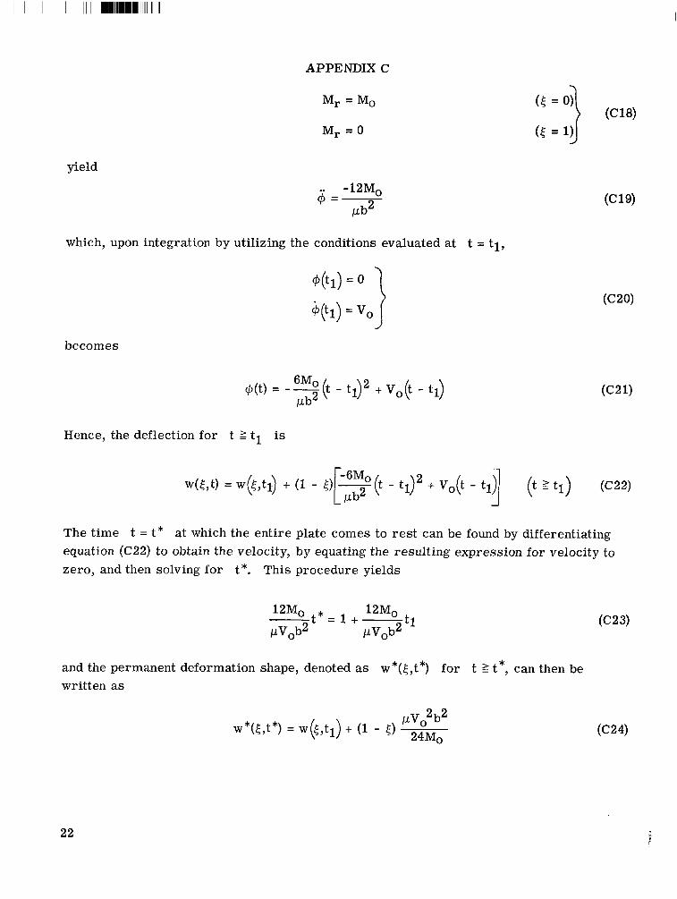
Mr = Mo
Mr = 0
yield
.. -12M0 @ = -
Pb2
which, upon integration by utilizing the conditions evaluated at t = tl ,
becomes
@(t) = -+t 6MO - t p + vo(t - tl) !Jb
Hence, the deflection for t 2 tl is
The time t = t * at which the entire plate comes to res t can be found by differentiating equation (C22) to obtain the velocity, by equating the resulting expression for velocity to zero, and then solving for t*. This procedure yields
and the permanent deformation shape, denoted as w*(E,t*) for t 2 t*, can then be written as
22

APPENDIX C
The permanent center deformation becomzs (eqs. (C15) and (C24) with 4 = 0)
23

REFERENCES
1. Souter, Robert K.; and Emerson, Joseph B.: Summary of Available Hail Literature and the Effect of Hail on Aircraft in Flight. NACA TN 2734, 1952.
2. Anon.: Tentative Airworthiness Standards for Supersonic Transports. Flight Stand- ards Service, FM, Nov. 1, 1965; Revision 4, Dec. 29, 1967.
3. Hayduk, Robert J.: The Response of a Single Wall Space Structure to Impact by Come- ta ry Meteoroids of Various Shapes. M.S. Thesis, Virginia Polytech. hst., 1968.
4. Thomson, Robert G.: Plastic Behavior of Circular Plates Under Transverse Impulse Loadings of Gaussian Distribution. NASA TR R-279, 1968.
5. Comm. on Metric Pract.: ASTM Metric Practice Guide. NBS Handbook 102, U.S. Dep. Com., Mar. 10, 1967.
6. Medick, M. A.: On Classical Plate Theory and Wave Propagation. ASME, Ser. E: J. Appl. Mech., vol. 28, no. 2, June 1961, pp. 223-228.
7. Hayduk, Robert J.: Response of an Infinite Elastic Plate to Axisymmetric Initial Velocity Distributions With Application to Hypervelocity Impact. 1969.
NASA TN D-5118,
8. Thomson, Robert G.; and Kruszewski, E. T.: Effect of Target Material Yield Strength on Hypervelocity Perforation and Ballistic Limit. Proceedings of the Seventh Hypervelocity Impact Symposium, vol. V, Feb. 1965, pp. 273-320. (Sponsored by U.S. Army, U.S. Air Force, and U.S. Navy.)
9. Fish, Richard H.; and Summers, J ames L.: The Effect of Material Properties on Threshold Penetration. Proceedings of the Seventh Hypervelocity Impact Sympo- sium, vol. VI, Feb. 1965, pp. 1-26. (Sponsored by U.S. Army, U.S. Air Force, and U.S. Navy.)
10. Alfaro-Bou, Emilio; and Thomson, Robert G.: Ballistic Limit of Aluminum Plates Determined by an Exploding Foil Gun Technique. NASA TN D-4259, 1967.
24

TABLE 1.- TARGET AND PROJECTILE MATERIAL PROPERTIES
AND VALUES O F THE MOMENTUM CONSTANT +
~~
Property I U.S. unit
(a) Target and projectile material properties
SI unit
Yield stress, o0 . . . . . . . Modulus of elasticity, E . . . Density, pt . . . . . . . . . . c = /fi . . . . . . . . . . .
~
68 000 psi 0.47 GN/m2
10.6 X lo6 psi 73.1 GN/m2
5.37 slugs/ft3 2767 kg/m3
16 900 ft/sec 5.15 km/s
. . . . . . . . Specific gravity I 0.916 I 0.916 I Density, pp . . . . . . . . . . 1.78 slugs/ft3
(b) Values of the momentum constant + computed from equation (7)
917 kg/m3
-7 Values of + at various projectile radii
a = 0.50 in. (1.27 cm)
0.70
a = 0.25 in. (0.64 cm)
0.71 0.72
I I .71 I .69 .70
0.063
.04
25
0.160
.10
Ini t ia l momentum distribution
Figure 1.- Elastic and r igid-plast ic regions.
26

.4
. 3
. 2
.1
0 .2 .4 . 6 .8 1.0
II
Figure 2.- I n i t i a l velocity d is t r ibut ion resul t ing f rom momentum balance between the spherical project i le and the target plate.
27

1.0
. 8
.6
Nondimensional moment
. 4
. 2
0
rl
Figure 3.- Typical moment distr ibutions i n central port ion of in f in i te elastic plate. ‘I = 1.5.
3.0 -
2.0
Dimensionless rad ius of b plastic region - a
I . 0
0
g o , m/s
200 400 600 800 1000
-
a = 0.50 in (1.27 cm
I I I I I
- 0.25 in (0.64 C m )
..
Z
Ski n t h ickn ess 0.04 in.(O. IO cm)
--- 0.063 in.(O. 160 cm) /E?’ 1000 2000 3000
Figure 4.- Radius of plastic region as a function of projectile velocity.
Figure 5.-
I
100
Projecti le velocity, go, m l s
1000 ~
IO0 I I 1 1 ' 1 I - i = = = i = - 1 7 7
impact
1 1 1000
Projecti le velocity, go, ft/s
Center deflection b as a funct ion of projectile velocity go. 0.063-inch-thick (0.160-cm) 2024-T4
11 10000
a luminum sheet; b = g,2eg5.
30

(a) Impact velocity, 330 ft/sec (0.10 km/s).
(b) Impact velocity, 500 fl/sec (0.15 km/s).
in.(O. I6 cm)
(c) Impact velocity, 1100 ff/sec (0.34 km/s).
Figure 6.- Var ia t ion in permanent deflection of 2024-T4 a luminum sheet impacted w i th I - inch-d iameter projecti le at various velocities. a = 0.50 in. (1.27 cm).
31
I. 00
c 0
V W
W
.I
-I-.
- - -0 . I O L .G c a- W
W
- 0
Projecti le velocity, go, m l s 1000 100
I I I l l 1 I I I I I I I I I
impact deflection
I I I -1.t I J .01 IO0 1000 10000
Projecti le velocity, go, f t l s
Figure 7.- Center deflection 6 as a funct ion of projectile velocity go. 0.M-inch-thick (0.10-cm) 2024-T4 a luminum sheet; 6 = g$.85.
32
41 3 y, I s hY3
IO0 IO00 I - T I I I I 1-
I . 00
c 0 e u al W
.- - re
:s 3 -- I= a, 0
. IO
Figure 8.- Center deflection 6 as a funct ion of =. $/3
10000
33

.T M
f M
L
34
Me 4
r M
Figure 9.- Tresca yield hexagon.
P i NASA-Langley, 1969 - 32 L-6494
NATIONAL AERONAUTICS AND SPACE ADMINISTRATION WASHINGTON, D. C. 20546
OFFICIAL BUSINESS FIRST CLASS MAIL
POSTAGE AND FEES PAID NATIONAL AERONAUTICS ANC
SPACE ADMINISTRATION
"The nero?mrtical and space nctiztities of the United States shall be coizditcted 10 ,ds t o contribztte . . . t o the expansion of h i m a n Knowl- edge of pheizortiena in ihe atmosphere and space. T h e Administration shd provide for the widest prncticable and appyopriate dissenzination of iizforitintion corzcerning its aciivities and the resiilts thereof?
L >
-' ' -NATIONAL AERONAUTICS AND SPACE ACT OF 1958
NASA SCIENTIFIC 'AND TECHNICAL PUBLICATIONS
TECHNICAL REPORTS: Scientific and technical information consideredaimportant, complete, and a lasting contribution to existing knowledge.
TECHNICAL NOTES: Informarion less broad in scope but nevertheless of imbortance as a contribution to existing knowledge.
TECHNICAL MEMORANDUMS : Information receiving limited distribution becaiise of preliminary data, security classifica- tion, or other reasons.
, .
. .
TECHNICAL TRANSLATIONS: Information published in a foreign language considered to merit NASA distribution in English.
SPECIAL PUBLICATIONS: Information derived from or of value to NASA activities. Publications include conference proceedings, monographs, data compilations, handbooks, sourcebooks, and special bibliographies.
TECHNOLOGY UTILIZATION PUBLICATIONS: Information on technology used by NASA that may be of particular interest in commercial and other non-aerospace applications. Publications include Tech Briefs, TEchno~ogy Utilization Reports and N ~ ~ ~ ~ , and Technology Surveys.
CONTRACTOR REPORTS: Scientific and technical information generated under a NASA contract or grant and considered an important contribution to existing knowledge.
Details on the availability of these publications may be obtained from:
SCIENTIFIC AND TECHNICAL INFORMATION DIVISION
NATIONAL AERONAUTICS AND SPACE ADMINISTRATION Washington, D.C. 20546