Embed Size (px)
Citation preview
.
N A S A T E C H N I C A L M E M O R A N D U M
I GPO PRICE $
CSFTl PRlCE(S) $
Hard copy (HC) .- Microfiche ( M F) -
ff 653 July 65
NASA TM X-52391
EXPLORING IN AEROSPACE ROCKETRY 4. THERMODYNAMICS
by Marshall C. Burrows Lewis Research Center Cleveland, Ohio
Presented to Lewis Aerospace Explorers Cleveland, Ohio 1966 -67
N
NATIONAL AERONAUTICS AND SPACE ADMINISTRATION WASHINGTON, D.C. 1968
https://ntrs.nasa.gov/search.jsp?R=19680010371 2018-07-03T07:04:47+00:00Z
EXPLORING IN AEROSPACE ROCKETRY
4. THERMODYNAMICS
Marshall C. Burrows
Presented to Lewis Aerospace Explorers Cleveland, Ohio
1966 -67
Advisor, James F. Connors
NATIONAL AERONAUTICS AND SPACE ADMINISTRATION
NASA Technical
Memorandum Chapter
1
2
3
4 I
5
6
7
8
9
10
11
12
13
14
15
16
17
18
19
20
21
AEROSPACE ENVIRONMENT John C. Evvard . . . . . . . . . . . . . . . . . . . . . . . . . . .
PROPULSION FUNDAMENTALS James F. Connors . . . . . . . . . . . . . . . . . . . . . . . . . .
CALCULATION OF ROCKET VERTICAL-FLIGHT PERFORMANCE John C. Evvard . . . . . . . . . . . . . . . . . . . . . . . . . . . .
THERMODYNAMICS Marshall C. Burrows . . . . . . . . . . . . . . . . . . . . . . . .
MATERIALS William D. Klopp . . . . . . . . . . . . . . . . . . . . . . . . . . .
SOLID-PROPELLANT ROCKET SYSTEMS Joseph F. McBride . . . . . . . . . . . . . . . . . . . . . . . . . .
LIQUID-PROPELLANT ROCKET SYSTEMS E. William Conrad . . . . . . . . . . . . . . . . . . . . . . . . . .
ZERO - GRAVITY EFFECTS William J. Masica . . . . . . . . . . . . . . . . . . . . . . . . . .
ROCKET TRAJECTORIES, DRAG, AND STABILITY Roger W. Luidens . . . . . . . . . . . . . . . . . . . . . . . . . .
SPACE MISSIONS Richard J. Weber . . . . . . . . . . . . . . . . . . . . . . . . . . .
LAUNCH VEHICLES Arthur V. Zimmerman . . . . . . . . . . . . . . . . . . . . . . . .
INERTIAL GUIDANCE SYSTEMS Daniel J. Shramo . . . . . . . . . . . . . . . . . . . . . . . . . . .
TRACKING John L. Pollack. . . . . . . . . . . . . . . . . . . . . . . . . . . .
ROCKETLAUNCHPHOTOGRAPHY William A. Bowles . . . . . . . . . . . . . . . . . . . . . . . . . .
ROCKET MEASUREMENTS AND INSTRUMENTATION Clarence C. Gettelman . . . . . . . . . . . . . . . . . . . . . . . .
ELEMENTS O F COMPUTERS Robert L . Miller . . . . . . . . . . . . . . . . . . . . . . . . . . .
ROCKET TESTING AND EVALUATION IN GROUND FACILITIES John H. Povolny. . . . . . . . . . . . . . . . . . . . . . . . . . . .
LAUNCH OPERATIONS Maynard I. Weston . . . . . . . . . . . . . . . . . . . . . . . . . .
NUCLEAR ROCKETS A. F. Lietzke. . . . . . . . . . . . . . . . . . . . . . . . . . . . .
ELECTRIC PROPULSION Harold Kaufman. . . . . . . . . . . . . . . . . . . . . . . . . . . .
BIOMEDICAL ENGINEERING KirbyW. Hiller. . . . . . . . . . . . . . . . . . . . . . . . . . . .
X-52388
X-52389
X-52390
X-52391
X - 523 92
X-52393
X-52394
X-52395
X-52396
X - 52397
X-52398
X-52399
X-52400
X - 5240 1
X - 52 402
X - 52 403
X-52404
X-52405
X-52406
X-52407
X - 52 408
iii
4. THERMODYNAMICS
Marshall C. Burrows*
By using the equations which were presented in chapter 2, it can be shown that specific impulse, or the pounds of force exerted by the rocket per pound of propellant flowing each second, is dependent on the composition and temperature of the combustion products. Therefore, studying the various kinds of propellants and noting what happens when they react or burn is important. Observing how fast heat is produced by each pound of propellant that enters the combustion chamber is also important, since this determines the size and weight of the chamber.
The study of propellants, their reactions, and the energy changes needed to perform work is called thermodynamics. This practical subject gives engineers many tools they need to improve systems that interchange energy and work. Some such systems a r e rocket engines, automotive engines , and even refrigerators. We will not concern our- selves with the details of this subject but will only examine several rules or laws of thermodynamics that are important to remember. The first rule concerns temperature, a term which we hear applied to the weather every day. The point to remember is that a group of bodies (or molecules) all at the same temperature are said to be in "thermal equilibrium" with each other. The second rule to remember is that we cannot get more useful energy out of a system than we put into it. In other words, we cannot get more useful thrust out of a rocket engine than we put into it in the form of energy-containing propellants. This is analogous to the adage which states that "you can't get something for nothing. I' The final rule that we will consider is that heat flows only from hotter to cooler bodies. cause the inventor forgot one of these basic rules. Even the refrigerator in your home obeys these rules. The fluid that absorbs heat from the inside of the box is compressed and pumped to the bottom or back of the refrigerator where heat is rejected to the room.
Now that we have discussed some rules which govern the operation of a rocket en- gine, we shall examine in greater detail the characteristics and combustion processes of some available propellants.
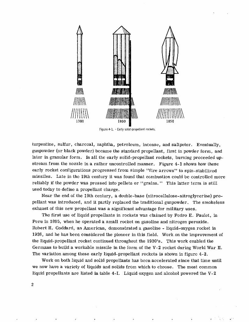
"arrows of flying fire" in the 13th century. Ingredients may have included tow, pitch,
Many novel methods of propelling a rocket engine have failed be-
The first genuine rocket propellant was probably made by the Chinese for their
* Aerospace Scientist, Rocket Combustion Section.
1111 Ill\\ 1850
Figure 4-1. - Early solid-propellant rockets.
turpentine, sulfur , charcoal, naphtha, petroleum, incense, and saltpeter. Eventually, gunpowder (or black powder) became the standard propellant, first in powder form, and later in granular form. In all the early solid-propellant rockets, burning proceeded up- stream from the nozzle in a rather uncontrolled manner. Figure 4-1 shows how these early rocket configurations progressed from simple "fire arrows" to spin-stabilized missiles. Late in the 19th century it was found that combustion could be controlled more reliably if the powder was pressed into pellets o r "grains. * ' This latter term is still used today to define a propellant charge.
pellant was introduced, and it partly replaced the traditional gunpowder. The smokeless exhaust of this new propellant was a significant advantage for military uses.
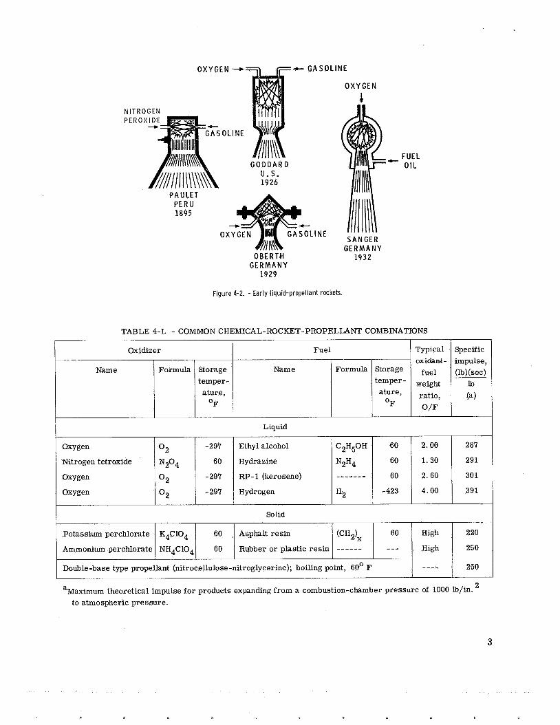
The first use of liquid propellants in rockets was claimed by Pedro E. Paulet, in Peru in 1895, when he operated a small rocket on gasoline and nitrogen peroxide. Robert H. Goddard, an American, demonstrated a gasoline - liquid-oxygen rocket in 1926, and he has been considered the pioneer in this field. Work on the improvement of the liquid-propellant rocket continued throughout the 1930's. This work enabled the Germans to build a workable missile in the form of the V-2 rocket during World War II. The variation among these early liquid-propellant rockets is shown in figure 4-2.
Work on both liquid and solid propellants has been accelerated since that time until we now have a variety of liquids and solids from which to choose. The most common liquid propellants a r e listed in table 4-1. Liquid oxygen and alcohol powered the V-2
Near the end of the 19th century, a double-base (nitrocellulose-nitroglycerine) pro-
2
O X Y G E N 4- F- G A S O L I N E
Oxidizer Fuel
Name Formula Storage Name Formula Storage
ature, ature, O F O F
temper-
N I PE
Typical oxidant -
fuel
ratio,
O D
weight
bOLINE
-297 Ethyl alcohol C2H50H 60
60
-297 RP-1 (kerosene) - - - - - - - 60
-423 -297 Hydrogen
Oxygen 0 2
Oxygen 0 2
Oxygen 0 2
Nitrogen tetroxide N2°4 60 Hydrazine N2H4
H2
G O D D A R D U.S . 1 9 2 6
2.00 287
1.30 291
2.60 301
4.00 391
PAULET P E R U 1 8 9 5
0 L I N E
Potassium perchlorate
Ammonium perchlorate
OBERTH G E R M A N Y
1 9 2 9
K4C104 60 Asphalt resin (CH,Ix 60 High 220
NH4C104 60 Rubber or plastic res in ------ --- High 250
O X Y G E N
c
Double-base type propellant (nitrocellulose-nitroglycerine); boiling point, 60' F
Figure 4-2. - Early l iquid-propellant rockets.
---- 250
FUEL - O I L
SANGER G E R M A N Y
1 9 3 2
3
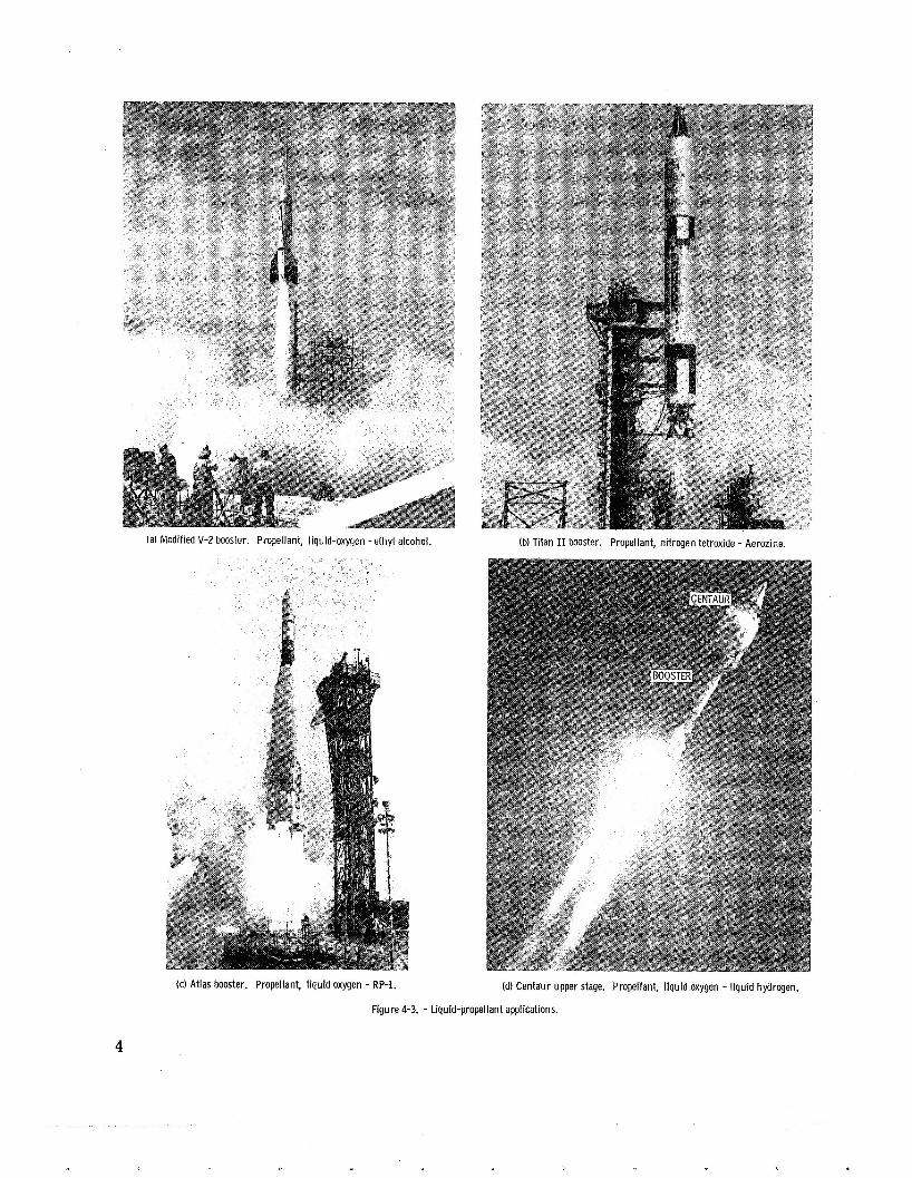
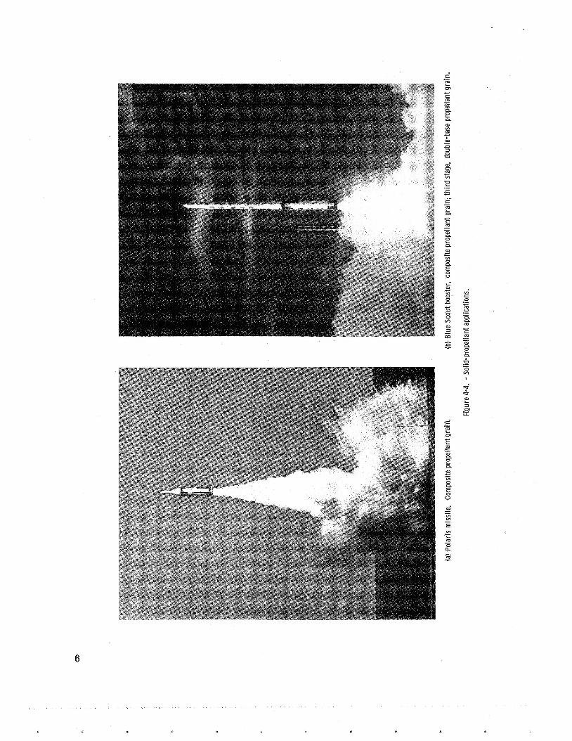
(a) Modified V-2 booster. Propellant, liquid-oxygen -ethyl alcohol. (b) Titan I1 booster. Propellant, nitrogen tetroxide - Aerozine.
(c) Atlas booster. Propellant, liquid oxygen - RP-1. (d) Centaur upper stage. Propellant, liquid oxygen - liquid hydrogen.
Figure 4-3. - Liquid-propellant applications.
4
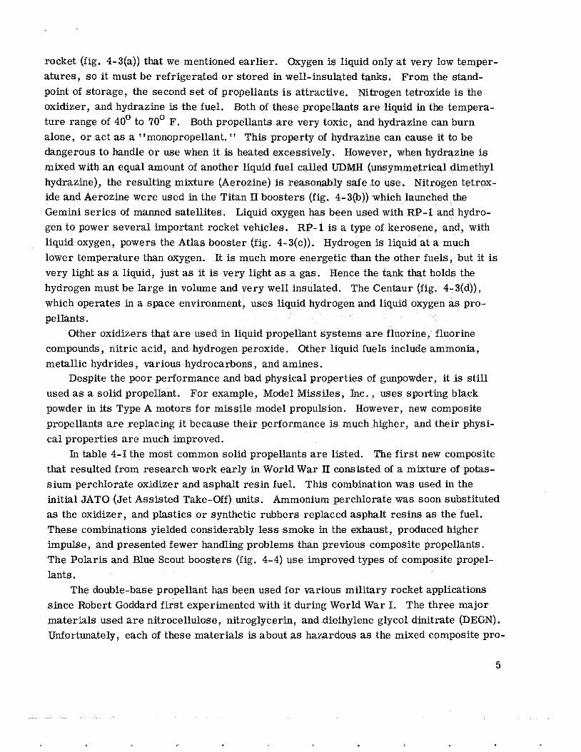
rocket (fig. 4-3(a)) that we mentioned earlier. Oxygen is liquid only at very low temper- atures, so it must be refrigerated o r stored in well-insulated tanks. From the stand- point of storage, the second se t of propellants is attractive. Nitrogen tetroxide is the oxidizer, and hydrazine is the fuel. Both of these propellants are liquid in the tempera- ture range of 40' to 70' F. Both propellants a r e very toxic, and hydrazine can burn alone, or act as a "monopropellant. '' This property of hydrazine can cause it to be dangerous to handle o r use when it is heated excessively. However, when hydrazine is mixed with an equal amount of another liquid fuel called UDMH (unsymmetrical dimethyl hydrazine), the resulting mixture (Aerozine) is reasonably safe to use. Nitrogen tetrox- ide and Aerozine were used in the Titan I1 boosters (fig. 4-3(b)) which launched the Gemini series of manned satellites. Liquid oxygen has been used with RP-1 and hydro- gen to power several important rocket vehicles. RP-1 is a type of kerosene, and, with liquid oxygen, powers the Atlas booster (fig. 4-3(c)). Hydrogen is liquid at a much lower temperature than oxygen. It is much more energetic than the other fuels, but it is very light as a liquid, just as it is very light as a gas. Hence the tank that holds the hydrogen must be large in volume and very well insulated. The Centaur (fig. 4-3(d)), which operates in a space environment, uses liquid hydrogen and liquid oxygen as pro- pellants.
compounds, nitric acid, and hydrogen peroxide. Other liquid fuels include ammonia, metallic hydrides, various hydrocarbons, and amines.
used as a solid propellant. For example, Model Missiles, Inc. , uses sporting black powder in its Type A motors for missile model propulsion. However, new composite propellants a r e replacing it because their performance is much .higher, and their physi- cal properties a r e much improved.
In table 4-1 the most common solid propellants a r e listed. The first new composite that resulted from research work early in World War 11 consisted of a mixture of potas- sium perchlorate oxidizer and asphalt resin fuel. This combination was used in the initial JATO (Jet Assisted Take-Off) units. Ammonium perchlorate was soon substituted as the oxidizer, and plastics o r synthetic rubbers replaced asphalt resins as the fuel. These combinations yielded considerably less smoke in the exhaust, produced higher impulse, and presented fewer handling problems than previous composite propellants. The Polaris and Blue Scout boosters (fig. 4-4) use improved types of composite propel- lants.
The double-base propellant has been used for various military rocket applications since Robert Goddard first experimented with it during World War I. The three major mater-hls used are nitrocellulose, nitroglycerin, and diethylene glycol dinitrate (DEGN) . Unfortunately, each of these materials is about as hazardous as the mixed composite pro-
Other oxidizers that are used in liquid propellant systems are fluorine, fluorine
Despite the poor performance and bad physical properties of gunpowder, it is still
5
.- a L 01
6
c I= m W - - n n
n
n
e W w m
W - a U
W- 01 m c VI
E 5 .- .- I= a L m .-
i W c z 0 n c 3 0 V lA
W 3 - m
VI
I= 0 c m u .- .- - n n m c I= a
I
f W L 3 01
L L .-
r' E .- 01 .,-. I= m W - - n n e W c
VI 0 LI
.-
5 0
W. - .- VI VI .- E VI
L m 0 a
.- -
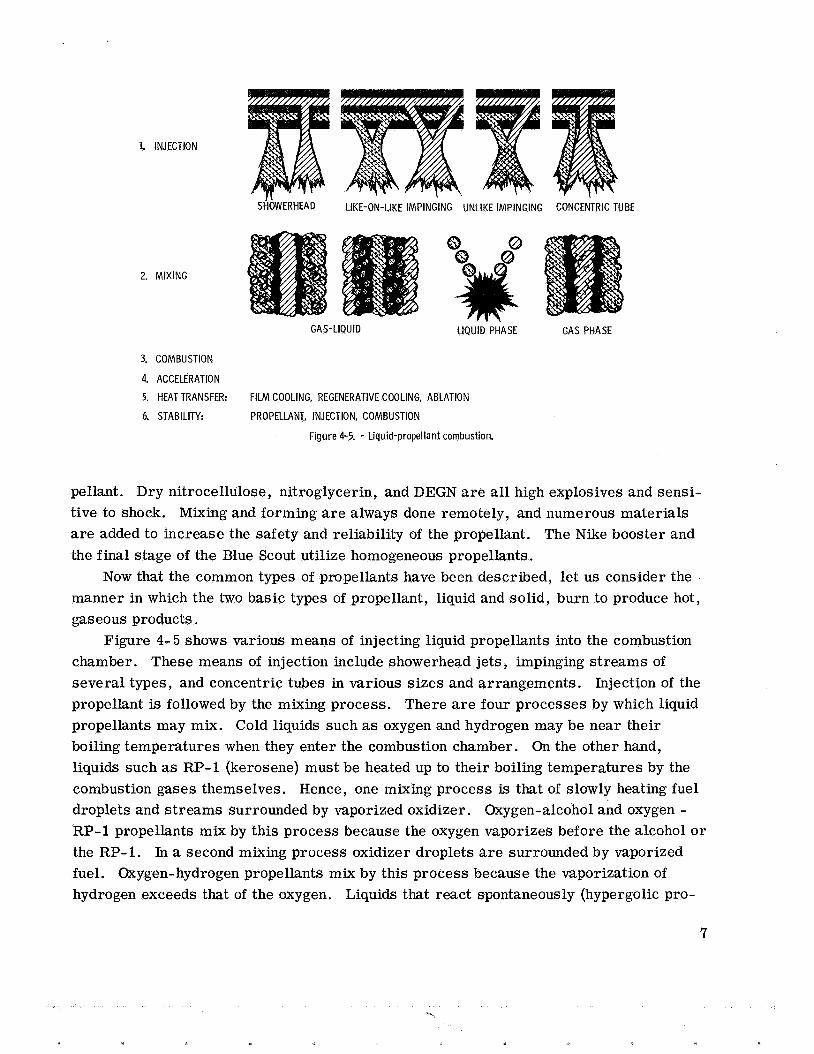
1. INJECTION
2. MIXING
S ~ ~ W E R H E A D LIKE-ON-LIKE IMPINGING UNLIKE IMPINGING CONCENTRIC TUBE
GAS-LIQUID
3. COMBUSTION
4. ACCELERATION
5. HEAT TRANSFER: FILM COOLING, REGENERATIVE COOLING,
6. STABILITY: PROPELLANT, INJECTION, COMBUSTION
LIQUID PHASE GAS PHASE
ABLATION
Figure 4-5. - Liquid-propellant combustion.
pellant. Dry nitrocellulose, nitroglycerin, and DEGN are all high explosives and sensi- tive to shock. Mixing and forming a r e always done remotely, and numerous materials are added to increase the safety and reliability of the propellant. The Nike booster and the final stage of the Blue Scout utilize homogeneous propellants.
manner in which the two basic types of propellant, liquid and solid, burn to produce hot, gaseous products.
chamber. These means of injection include showerhead jets, impinging streams of several types, and concentric tubes in various sizes and arrangements. Injection of the propellant is followed by the mixing process. There are four processes by which liquid propellants may mix. Cold liquids such as oxygen and hydrogen may be near their boiling temperatures when they enter the combustion chamber. On the other hand, liquids such as RP-1 (kerosene) must be heated up to their boiling temperatures by the combustion gases themselves. Hence, one mixing process is that of slowly heating fuel droplets and streams surrounded by vaporized oxidizer. Oxygen-alcohol and oxygen - RP-1 propellants mix by this process because the oxygen vaporizes before the alcohol o r the RP-1. In a second mixing process oxidizer droplets are surrounded by vaporized fuel. Oxygen-hydrogen propellants mix by this process because the vaporization of hydrogen exceeds that of the oxygen. Liquids that react spontaneously (hypergolic pro-
Now that the common types of propellants have been described, let us consider the
Figure 4-5 shows various means of injecting liquid propellants into the combustion
7
c.,
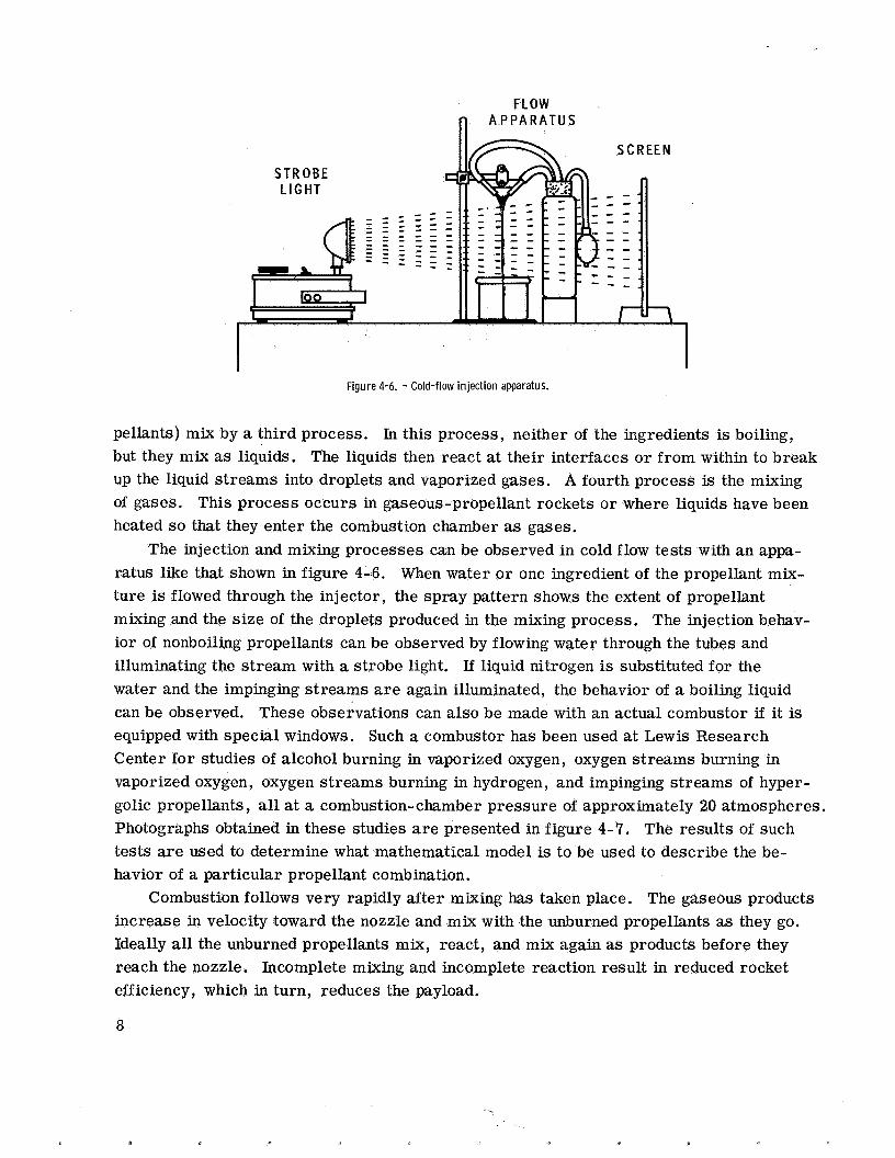
FLOW fl A P P A R A T U S
Figure 4-6. - Cold-flow inject ion apparatus.
pellants) mix by a third process. In this process, neither of the ingredients is boiling, but they mix as liquids. The liquids then react at their interfaces or from within to break up the liquid streams into droplets and vaporized gases. A fourth process is the mixing of gases. This process occurs in gaseous-propellant rockets o r where liquids have been heated so that they enter the combustion chamber as gases.
The injection and mixing processes can be observed in cold flow tests with an appa- ratus like that shown in figure 4-6. When water or one ingredient of the propellant mix- ture is flowed through the injector, the spray pattern shows the extent of propellant mixing and the size of the droplets produced in the mixing process. The injection behav- ior of nonboiling propellants can be observed by flowing water through the tubes and illuminating the stream with a strobe light. If liquid nitrogen is substituted for the water and the impinging s t reams are again illuminated, the behavior of a boiling liquid can be observed. These observations can also be made with an actual combustor if it is equipped with special windows. Such a combustor has been used at Lewis Research Center for studies of alcohol burning in vaporized oxygen, oxygen streams burning in vaporized oxygen, oxygen streams burning in hydrogen, and impinging streams of hyper- golic propellants, all at a combustion-chamber pressure of approximately 20 atmospheres. Photographs obtained in these studies are presented in figure 4-7. The results of such tests a r e used to determine what mathematical model is to be used to describe the be- havior of a particular propellant combination.
increase in velocity toward the nozzle and mix with the unburned propellants as they go. Ideally all the unburned propellants mix, react, and mix again as products before they reach the nozzle. Incomplete mixing and incomplete reaction result in reduced rocket efficiency, which in turn, reduces the payload.
Combustion follows very rapidly after mixing has taken place. The gaseous products
8
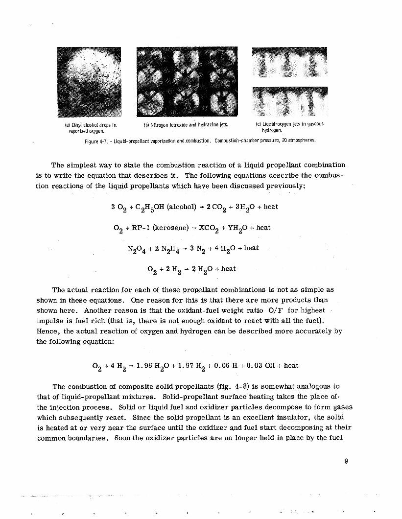
(a) Ethyl alcohol drops in (b) Nitrogen tetroxide and hydrazine jets. (c) Liquid-oxygen jets in gaseous vaporized oxygen. hydrogen.
Figure 4-7. - Liquid-propellant vaporization and combustion. Combustion-chamber pressure, 20 atmospheres.
The simplest way to state the combustion reaction of a liquid propellant combination is to write the equation that describes it. The following equations describe the combus- tion reactions of the liquid propellants which have been discussed previously:
3 O2 + C2H50H (alcohol) - 2 C02 + 3H20 + heat
O2 + RP-1 (kerosene) - XC02 + YH20 + heat
N204 + 2 N2H4 - 3 N2 + 4 H 2 0 + heat
O2 + 2 H2 - 2 H 2 0 + heat
The actual reaction for each of these propellant combinations is not as simple as shown in these equations. One reason for this is that there are more products than shown here. Another reason is that the oxidant-fuel weight ratio O/F for highest impulse is fuel rich (that is, there is not enough oxidant to react with all the fuel). Hence, the actual reaction of oxygen and hydrogen can be described more accurately by the following equation:
O 2 + 4 H 2 - 1 . 9 8 H 2 0 + 1 . 9 7 H 2 + O . 0 6 H+O.O3OH+heat
The combustion of composite solid propellants (fig. 4-8) is somewhat analogous to that of liquid-propellant mixtures. Solid-propellant surface heating takes the place of the injection process. Solid o r liquid fuel and oxidizer particles decompose to form gases which subsequently react. Since the solid propellant is an excellent insulator, the solid is heated at o r very near the surface until the oxidizer and fuel start decomposing at their common boundaries. Soon the oxidizer particles are no longer held in place by the fuel
9
x
1. B U R N I N G R A T E
2. M I X I N G
3. C O M B U S T I O N
4. A C C E L E R A T I O N
5. H E A T TRANSFER:
6. S T A B I L I T Y :
P R O P E L L A N T , A D D l T l V E S , I N H I 9 I T O R
P R O P E L L A N T , C O N F I G U R A T I O N , C O M B U S T I O N
Figure 4-8. - Composite-propellant combustion.
binder, and they break loose to be carried along in the gas stream with the decomposing binder. Other materials such as metallic particles of aluminum a r e sometimes added to the composite propellant for better combustion and higher impulse. Also, the burning aluminum is a great aid in the observation of the burning of the propellant (fig. 4-9).
the oxidizer and fuel of the double-base propellant are chemically mixed rather than just in physical proximity to each other. In order to describe the burning of a double-base propellant it is necessary to consider three zones called the foam, fizz, and flame zones. Heating very close to the surface melts some of the propellant and causes some low-
The reaction of a double-base propellant is different from that of a composite because
Figure 4-9. - B u r n i n g composite propellant w i t h added aluminum. Pressure, 1 atmosphere.
10
temperature reactions. Bubbles of gas are released (foam zone) which rise and enter the fizz zone, where the remaining propellant decomposes. Final reactions and flame tem- perature occur in the flame zone.
propellants. The following discussion pertains to the combustion chamber. At the end of the chamber opposite the nozzle, there is an injector in the liquid-propellant engine, and there is usually a layer of solid propellant and inhibitor in the solid-propellant engine. In the liquid-propellant engine there is sufficient liquid entering the combustion chamber from the propellant manifold to prevent melting or burning of the injector face. However, care must be taken to prevent very hot, oxidizer gases from hitting the surface of the chamber wal l at high velocity, because these gases can act just like a cutting torch. In the solid-propellant engine, a layer of propellant and inhibitor prevents overheating of the combustion-chamber walls, so the walls need only be strong enough to withstand the chamber pressure. As the solid propellant is burned away, the inhibitor acts as a heat shield and as a very slow burning fuel (fig. 4-10). Latex paint is a good example of an inhibitor.
Thus far the discussion has centered on the characteristics and the behavior of the
Figure 4-10. - B u r n i n g strand of solid propellant.
The combustion-chamber wal ls of a liquid-propellant engine are more complex than those of a solid-propellant engine. One of the liquid propellants, usually the fuel, passes at high velocities through thin tubes on i t s way to the injector. The tubes form part of the outside chamber walls, This procedure is called regenerative cooling and helps to prevent overheating of the chamber walls. Sometimes regenerative cooling is not suffi- cient to ensure cool walls. Then part of the liquid fuel is sprayed on the inner surfaces of the walls to act as a liquid o r vapor shield against the heat from the combustion
11

gases. This procedure is known as film cooling. Of course, the walls must be strong enough to contain the chamber pressure.
(regenerative and film cooling). But the nozzle of a solid-propellant engine is necessarily uncooled. Therefore, it is made of a strong heat-resistant material such as tungsten, graphite,' o r a metal-ceramic combination.
chamber walls. These cool gases help to shield the walls from the high-velocity, hot gases in the center of the chamber. If the cool gases are removed, the wall surfaces may burn out in the liquid-propellant engine, or they may erode in the solid-propellant engine. Pressure oscillations within the chamber can have the same effects, and they can even rupture the chamber walls themselves. These pressure oscillations are known as combustion instability. One form of combustion instability is called chugging and is characterized by severe oscillations in pressure at 1 ow frequencies (<lo0 cps). Another form of combustion instability is characterized by severe, high-f requency oscillations in pressure and is called screaming.
low and high velocities. The chamber pressure then responds to this flow behavior. Chugging may not be destructive to the engine itself, but it can result in violent shaking of the whole rocket structure.,
Screaming can be compared to the pressure vibrations in pipe-organ tubes. Pres- sure waves can travel at sonic velocities up and down the chamber length, around it, across it, o r radially in and out (fig. 4-11). All these high-frequency oscillations have been measured in research engines. Waves around the chamber have recently been pro- duced in a specially built engine which can burn liquid propellants (02 and H2) o r solid composite propellants. Figure 4-12 shows stable and unstable combustion with both types of propellant
The nozzle of a liquid-propellant engine is cooled the same way as the chamber walls
Normally, there are low-velocity, cool gases close to the inside surfaces of the
Chugging can be compared to a surging in which the propellants flow alternately at
0 - J ) LONGlTU DlNAL @ RADIAL
STANDING TRANSVERSE SPINNING TRAN SVER Si
Figure 4-11. - Fundamental modes of acoustic combustion instability.
12
STABLE TRANSITION UNSTABLE
(a) Combustion of liquid-oxygen - l iquid-hydrogen propellant.
STABLE TRANSITION UNSTABLE
(b) Combustion of composite propellant.
Figure 4-12. - Screaming in l iquid- and solid-rocket combustors.
13
In this chapter, a general discussion of the development, uses, burning processes, and problems of propellants has been presented. However, no attempt has been made to select the "best" propellant, injection method, or combustion-chamber shape. There really is no absolute best in these things, because no one propellant has all the desirable characteristics, and because the combustion-system hardware must be optimized for each propellant combination. The principal desirable features of propellants and of com- bustion systems are presented in the following lists. Propellants :
(1) High chemical energy (high impulse, high temperature) (2) Low molecular weight of combustion products (3) Chemical stability during storage (4) Small variation of physical properties with temperature (5) No change in state at storage temperature (6) High propellant density (7) Predictable physical and combustion characteristics (8) Easily ignitable, but safe and nontoxic during storage (9) Stable, efficient burning behavior
(10) Nonluminous, smokeless, nontoxic exhaust
Combustion systems: (1) Injector o r grain optimized for most stable, efficient combustion (2) Use of minimum chamber volume necessary for maximum system efficiency (3) Nozzle shape optimized for propellants and mission
14
GLOSSARY
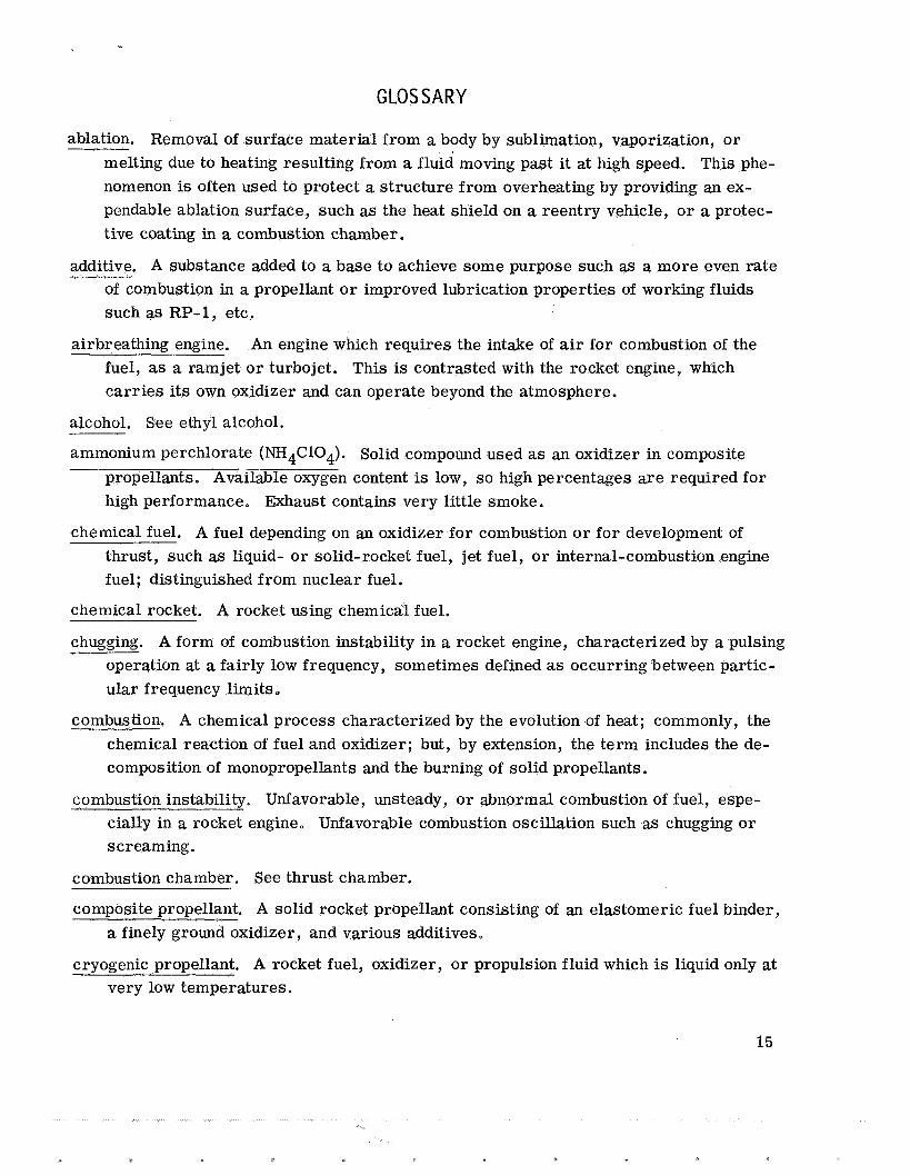
ablation. Removal of surface material from a body by sublimation, vaporization, or melting due to heating resulting from a fluid moving past it at high speed. This phe- nomenon is often used to protect a structure from overheating by providing an ex- pendable ablation surface, such as the heat shield on a reentry vehicle, or a protec- tive coating in a combustion chamber.
additive. A substance added to a base to achieve some purpose such as a more even rate of combustion in a propellant o r improved lubrication properties of working fluids such as RP-1, etc.
airbreathing engine. An engine which requires the intake of air for combustion of the fuel, as a ramjet or turbojet. This is contrasted with the rocket engine, which carr ies its own oxidizer and can operate beyond the atmosphere.
alcohol. See ethyl alcohol.
ammonium perchlorate (NH4C104). Solid compound used as an oxidizer in composite propellants. Available oxygen content is low, so high percentages are required for high performance, Exhaust contains very little smoke.
chemical fuel. A fuel depending on an oxidizer for combustion or for development of thrust, such as liquid- or solid-rocket fuel, jet fuel, or internal-combustion engine fuel; distinguished from nuclear fuel.
chemical rocket. A rocket using chemical fuel.
chugging. A form of combustion instability in a rocket engine, characterized by a pulsing operation at a fairly low frequency, sometimes defined as occurring between partic- ular frequency limits
combustion. A chemical process characterized by the evolution of heat; commonly, the chemical reaction of fuel and oxidizer; but, by extension, the term includes the de- composition of monopropellants and the burning of solid propellants.
combustion instability. Unfavorable, unsteady, or abnormal combustion of fuel, espe- cially in a rocket engine, Unfavorable combustion oscillation such as chugging or screaming.
combustion chamber. See thrust chamber.
composite propellant. A solid rocket propellant consisting of an elastomeric fuel binder, a finely ground oxidizer, and various additives,
cryogenic propellant. A rocket fuel, oxidizer, or propulsion fluid which is liquid only at very low temperatures.
15
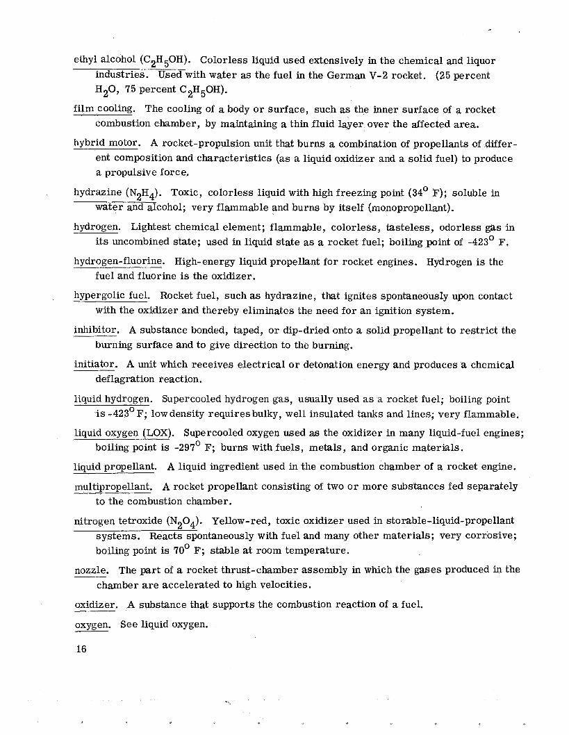
ethyl alcohol (C2H50H). Colorless liquid used extensively in the chemical and liquor industries. Used with water as the fuel in the German V-2 rocket. (25 percent H20, 75 percent C2H50H).
combustion chamber, by maintaining a thin fluid layer over the affected area. film cooling. The cooling of a body o r surface, such as the inner surface of a rocket
hybrid motor. A rocket-propulsion unit that burns a combination of propellants of differ- ent composition and characteristics (as a liquid oxidizer and a solid fuel) to produce a propulsive force.
hydrazine (N2H4). Toxic, colorless liquid with high freezing point (34' F); soluble in water and alcohol; very flammable and burns by itself (monopropellant).
its uncombined state; used in liquid state as a rocket fuel; boiling point of -423' F. hydrogen. Lightest chemical element; flammable, colorless, tasteless, odorless gas in
hydrogen-fluorine. High-energy liquid propellant for rocket engines. Hydrogen is the fuel and fluorine is the oxidizer.
hypergolic fuel. Rocket fuel, such as hydrazine, that ignites spontaneously upon contact with the oxidizer and thereby eliminates the need for an ignition system.
inhibitor. A substance bonded, taped, o r dip-dried onto a solid propellant to restrict the burning surface and to give direction to the burning.
initiator. A unit which receives electrical o r detonation energy and produces a chemical deflagration reaction.
liquid hydrogen. Supercooled hydrogen gas, usually used as a rocket fuel; boiling point is -423' F; low density requires bulky, well insulated tanks and lines; very flammable.
boiling point is -297' F; burns with fuels, metals, and organic materials. liquid oxygen (LOX). Supercooled oxygen used as the oxidizer in many liquid-fuel engines;
liquid propellant. A liquid ingredient used in the combustion chamber of a rocket engine.
multipropellant. A rocket propellant consisting of two o r more substances fed separately to the combustion chamber.
nitrogen tetroxide (N204). Yellow-red, toxic oxidizer used in storable-liquid-propellant systems. Reacts spontaneously with fuel and many other materials; very corrosive; boiling point is 70' F; stable at room temperature.
nozzle. The part of a rocket thrust-chamber assembly in which the gases produced in the chamber are accelerated to high velocities.
oxidizer. A substance that supports the combustion reaction of a fuel.
oxygen. See liquid oxygen.
16
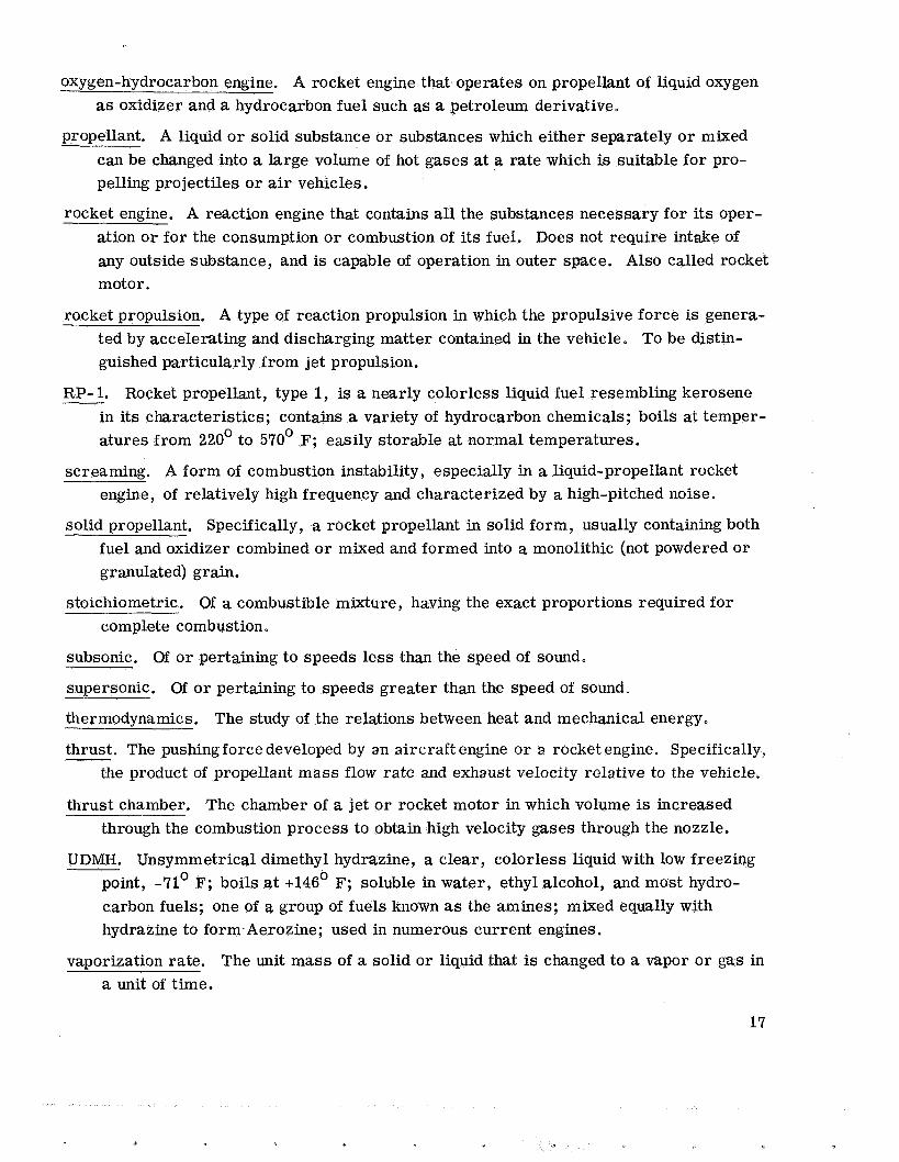
oxygen-hydrocarbon engine. A rocket engine that operates on propellant of liquid oxygen as oxidizer and a hydrocarbon fuel such as a petroleum derivative.
propellant. A liquid o r solid substance or substances which either separately or mixed can be changed into a large volume of hot gases at a rate which is suitable for pro- pelling projectiles or air vehicles.
rocket engine. A reaction engine that contains all the substances necessary for its oper- ation or for the consumption or combustion of its fuel. Does not require intake of any outside substance, and is capable of operation in outer space. Also called rocket motor.
rocket propulsion. A type of reaction propulsion in which the propulsive force is genera- ted by accelerating and discharging matter contained in the vehicle, To be distin- guished particularly from jet propulsion.
RP- 1. Rocket propellant, type 1, is a nearly colorless liquid fuel resembling kerosene in its characteristics; contains a variety of hydrocarbon chemicals; boils at temper- atures from 220' to 570' F; easily storable at normal temperatures.
screaming. A form of combustion instability, especially in a liquid-propellant rocket engine, of relatively high frequency and characterized by a high-pitched noise.
solid propellant. Specifically, a rocket propellant in solid form, usually containing both fuel and oxidizer combined or mixed and formed into a monolithic (not powdered o r granulated) grain.
stoichiometric. Of a combustible mixture, having the exact proportions required for complete combustion.
subsonic. Of o r pertaining to speeds less than the speed of sound.
supersonic. Of o r pertaining to speeds greater than the speed of sound,
thermodynamics.
thrust. The pushingforce developed by an aircraft engine o r a rocket engine. Specifically, the product of propellant mass flow rate and exhaust velocity relative to the vehicle.
The study of the relations between heat and mechanical energy.
thrust chamber. The chamber of a jet or rocket motor in which volume is increased through the combustion process to obtain high velocity gases through the nozzle.
UDMH. Unsymmetrical dimethyl hydrazine, a clear, colorless liquid with low freezing point, -71' F; boils at ~146' F; soluble in water, ethyl alcohol, and most hydro- carbon fuels; one of a group of fuels known as the amines; mixed equally with hydrazine to form.Aerozine; used in numerous current engines.
vaporization rate. The unit mass of a solid o r liquid that is changed to a vapor or gas in a unit of time.
17
BIBLIOGRAPHY
Hill, Philip G , ; and Peterson, Carl R. : Mechanics and Thermodynamics of Propulsion. Addison-Wesley Publ. Co., 1965.
Sutton, George P. : Rocket Propulsion Elements. Third ed., John Wiley and Sons, 1963.
Siegel, Bernard; and Schieler , Leroy: Energetics of Propellant Chemistry. John Wiley and Sons, Inc., 1964.
NASA-CLEVELAND, OHIO E-3364-4
18