Embed Size (px)
Citation preview

*/
NASA Technical Memorandum 1 0 0 5 3 1
.
MODERN WING FLUTTER ANALYSIS BY COMPUTATIONAL FLUID DYNAMICS METHODS
(WASA-TH-toQ531) 1OD&E11 U I I C PLOTTER 188-1 4965 AEALYSIS BY COPlWTATXOIAL FLUID DYIIAMXCS HETBODS [UASA) 11 p CSCL OlA
tlaclas 63/02 0118990 -
HERBERT J. CUNNINGHAM JOHN T. BATINA ROBERT M. BENNETT
JANUARY 1988
National Aeronautics and Space Administration
Langley Research Center Harnpton, Virginia 23665-5225
https://ntrs.nasa.gov/search.jsp?R=19880005583 2018-08-31T11:04:54+00:00Z

MODERN WING FLUrrER ANALYSIS BY COMPUTATIONAL FLUID DYNAMICS METHODS
ABSTRACT
Herbert J. Cunningham John 1. B a t h
Robert M. Bennett
Unsteady Aerodynamlcr Branch Loads and Aeroelasticlty Division
NASA Langley Research Center Hampton, Virglnla 23665-5225
INTRODUCTION
The paper describes the application and assessment of the recently-developed CAP-TSD transonic small-disturbance code for flutter prediction. The CAP-TSD code has been developed for aeroelastic analysis of complete aircraft configurations and was previously applied to the calculation of steady and unsteady pressures with favorable results. Generalized aerodynamic forces and flutter characteristics are calculated and compared in the present study with linear theory results and with experimental data for a 450 sweptbadc wing. These results are in good agreement with the experimental flutter data which Is the first step toward validating CAP-TSD for general transonic aeroelastic applications. The paper presents these results and comparisons along with general remarks regarding modern wing flutter analysis by computational fluid dynamics methods.
NOMENCLATURE
Aij
P (0, (0j. (0a
generalized aerodynamic force coefficient from the surface integral of hi Api/[c2pU2/2] reference length, c12 reference length; root chord coefficient of lifting pressure, Ap/(pU2/2) reduced frequency, (0 W U freestream Mach number lifting pressure; time marching value and that for mode hi, respectively; positive up generalized coordinate of motion for mode I time freestream speed right-hand orthogonal coordinates ratio of wing mass to mass of air in the truncated cone that encloses the wing freestream flow density circular frequency, in general; of mode j and of the first torsion mode, respectively
Research on the application of computational fluid dynamics (CFD) methods to unsteady flows and aeroelastic analysis is presently being actively pursued. Edwards and Thomas (1) gave a recent survey, for example, on computational methods for unsteady transonic flows with emphasis on applications to aeroelastic analysis and flutter prediction. The transonic speed range is of primary interest because the flutter dynamic pressure is typically critical (i.e., lower) there. The main effort. especially for three-dimensional configurations, has been at the transonic small disturbance (TSD) equation level, of which the XTRAN3S program is an important example (2). For the higher equation levels such as the Euler and Navier-Stokes equations, efforts on aeroelastic applications have been limited to simple two-dimensional airfoils because of the larger computational cost involved. Two recent efforts are reported by Bendiksen and Kousen (3) and by Wu, Kaza, and Sankar (4).
The advantage of the TSD formulation, though, is the relatively low computational cost. the simplicity of the gridding and geometry preprocessing, and the ability to treat complete aircraft configurations. The XTRAN3S code, for example, employs an alternating-direction implicit (ADI) finite- difference algorithm for solution of the TSD equation, with several terms treated explicitly. This type of solution has a numerical stability restriction, however, that requires a large number of sufficiently small time steps, often much smaller than are needed for a time-accurate solution of the physical process. Batina (5) described the development of a time-accurate approximate factorization (AF) algorithm applied to the TSD equation. The AF algorithm was devebped to alleviate or avoid the numerical stability restriction of the AD1 algorithm. Furthermore, the rate of convergence per time step is greatly enhanced by the AF procedure, which reduces proportionately the cost of computation.
The AF algorithm has subsequently been developed into a new computer code called CAP-TSD (for Gomputational Aeroelasticlty Erogram - Iransonic Small Usturbance) for transonic aeroelastic analysis of complete aircraft configurations (6).

The CAP-TSD program emphasizes a combination of economy, stability, and accuracy of calculation. CAP-TSD has been used to calculate steady and unsteady pressures on wings and configurations at subsonic, transonic. and supersonic Mach numbers. Comparisons of these results with other methods and with experimental data have been favorable (Refs. (6) and (7)). However, the CAP-TSD code has been developed primarily for aeroelastic analysis. Such analysis involves the coupling of the aerodynamics with the structural characteristics of the configuration under consideration. The resulting equations of motion for a time-domain or time-marching aeroelastic analysis are based upon the aircraft natural vibration modes. These equations are integrated in time along with the finite- difference solution of the flow field. Initial conditions for each mode are input and free decay transients are calculated. Aeroelastic stability is then deduced from the free decay records or time histories. Both the underlying theory and the numerical procedures require evaluation. Thus, the purpose of the present paper is to report on the preliminary results of this evaluation. Generalized aerodynamic forces and flutter boundaries are presented for a 450 sweptback wing. Comparisons of these results with parallel linear theory calculations as well as with the experimental flutter data of Yates, et al. (8) provide an assessment of CAP-TSD for aeroelastic applications. The paper presents these results and comparisons along with general remarks regarding modern wing flutter analysis by CFD methods.
COMPUTATIONAL PROCEDURES
In this section, the computational procedures are described including the CAP-TSD code, the aeroelastic equations of motion, the time-marching solution of these equations, and the modal identification of the resulting free decay transients. Although the emphasis of the discussion is on the CAP-TSD code, the general computational procedures regarding time-marching flutter analysis apply to other CFD codes as well.
The CAP-TSD code is a finite-difference program which solves the general-frequency modified transonic small- disturbance (TSD) equation. The TSD potential equation is defined by
The linear potential equation is recovered by simply sening F, 0, and H equal to zero.
Equation (1) is solved within CAP-TSD by a time-accurate approximate factorization (AF) algorithm developed by Batina (5). In Refs. (5) to (7), the AF algorithm was shown to be efficient for application to steady or unsteady transonic flow problems. It can provide accurate solutions in only several a hundred time steps yielding a significant computational cost savings when compared to alternative methods. Recently several algorithm modifications have been made which improve the stability of the AF algorithm and the accuracy of the results (9). These algorithm modifications include: (1) Engquist-Osher (E-0) type-dependent differencing to more accurately and efficiently treat regions of supersonic flow, (2) extension of the E-0 switch for second-order-accurate upwind differencing in supersonic regions to improve the accuracy of the results. (3) nonreflecting far fieid boundary conditions for more accurate unsteady applications, and (4) several modifications which accelerate convergence to steady state. The capabilities employed in the present study include the E-0 switch and the nonreflecting boundary conditions. The CAP-TSD code can treat configurations with arbitrary combinations of lifting surfaces and bodies including canard, wing, tail, control surfaces, tip launchers, pylons, fuselage, stores, and nacelles. Results have been presented for several complex aircraft configurations in Ref. (6). The calculated results were in good agreement with available experimental pressure data which validated CAP-TSD for multiple component applications with mutual aerodynamic Interference effects.
s of MollQn
The aeroelastic equations of motion which have been incorporated in CAP-TSD are based on a right-hand orthogonal coordinate system with the x-direction defined as positive downstream and the z-direction positive upward. The presentation herein is limited to the case of an isolated wing with motion in the z-direction from an undisturbed position in the z = 0 plane. The general motion of the wing is assumed to be described by the separation of time and space variables
( 3 )
Several choices are available for the coefficients F. G, and H depending upon the assumptions used in deriving the TSD equation. For transonic applications, the coefficients are herein defined as
1 2 2
F = - - ( y + l ) M
1 G = 7 (7- 3) M2
L
and further that the motion can be well approrimated as a finite modal series
where for each mode, hi is the mode shape and qi is the generalized coordinate of modal motion. The equations of motion are then formulated by considering Lagrange's equations. The principal of virtual work as expressed by a set of Lagrange's equations (one equation per mode i) is
2

where T is the kinetic energy, U is the potential energy of the structure, and Qi is the generalized force aslloclated with qi, which is obtained from the virtual work due to the external (aerodynamic) forces. The kinetic energy is
where S is the planform area and dWdS is the area distrikrtbn of wing mass. The potential energy is
( 7 )
where o(x,y) represents the effective stiffness rate of the wing elastic restoring force.
Application of Lagrange's equations in the absence of external forces gives
For a linear (or nearly linear) structure in the absence of external forces
where a is the circular frequency of vibratory motion. From Eq. (8) this gives for each normal mode j
which is the usual Rayl€ilgh-type representation for replacing the elastic restoring forces involving u in terms of the mass- inertia terms involving dWdS.
4
b
The virtual work bW done by the lifting pressure Ap acting through the virtual displacement hi 6 qi Is then
e-- ''' c2Jhi-- Ap dS
s pu2/2 c2 2
is the generalized aerodynamic force associated with the lifting pressure Ap. and with the virtual work weighting mode hi. The resulting set of equatbns of motbn Is
where M is the generalized mass matrix, K is the stiffness matrix, and 0 is the vector of generalized aerodynamic forces. From Eq. (13)
tlc sol-
The aeroelastk soluHon procedure implemented within CAP- TSD for Integrating Eq. (14) is similar to that described by Edwards, et. el. (10). Reference (10) describes for a lwo- dimensional. two-degree-of-freedom system an aeroelastic solution in terms of a state equation formulation. Here, by a parallel formulation, a linear state equation is developed from Eq. (14). Each element of Eq. (14) is a normal mode equation which may be expressed in first-order state-space form as
xi = Axi + Bui
where
-1 pu2 2 [ ;] B = m i -c 2
ui = [ J AC P ' h. dS/cz] S
AP AC,, - pu2n
from which
3

In these definitions, mi and ki are elements of the mass and stiffness matrices, respectively, corresponding to mode I. Equation (15) is a finite-dimensional linear dlfferentlal equation and its solution is given by
Amplitude
t
xi(t) = @(t) xi(0) + jexp [A (t - z)] Bu (z) d.r ( 1 6 ) 0
r
Mode4 -- .
The state transition matrix @(t) - exp [At], In general, can be calculated to any assigned accuracy by using a sufficient number of terms of the series expansion of the matrix exponential function. For the aeroelastic problem considered here, O(1) is computed exactly using simple closed-form expresslons for each element of the matrix. As explained in Ref. (lo), the first term in Eq. (16) is the homogeneous response portion of Eq. (15). while the second term Is a convolution Integral which represents the forced response. Numerically, the solution Is advanced from any time step n to step n + 1, by
xi [(n + l)At] = 0 (At) xi (nAt)
I (n+t)At
+ I exp [A ((n + 1) At - T)] Bu (z) d% ( 1 7 ) I nAt
~
I
~
where At is the step size. The simplest approximation for the integral is to assume that u(s) is constant, u(f) = u(nAt). A betler approximation is to assume that u varies linearly from un to un+l, estimating un+l as un + (un - un-1). The resulting algorithm is
n+l xi = cp x; + e B (3u" - Un-l) n
where e is the integral of the state-transltlon matrix O. Reference (1 1) describes a comparative evaluation of seven alternative structural integration algorithms Including that of Eq. (18). The modified state-transition matrix Integrator of Eq. (18) was shown to be superior to the others In terms of numerical stability and accuracy.
For aeroelastic analysis, two steps are generally required in performing the calculations. In the first step. the steady-state flow field is calculated to account for wing thickness, camber, and mean angle of attack thus providing the starting flow field for the aeroelastic analysis. The second step is to prescribe an initial disturbance to begin the structural integration. Disturbance velocities in one or more modes, rather than displacements, have been found to be distinctly superior in avoiding nonphysical, strictly numerical transients and their possible associated instabilities. For the applications presented below, 1000 time steps were typically used to compute about three cycles of the dominant flutter mode and about 20 cycles of the higher frequency fourth mode (second torsion). In determining a flutter point, the freestream Mach number M and the associated freestream speed U were held fixed. A judiciously chosen value of the dynamic pressure pU2M Is used to compute the free decay transients. These resulting transients of the
generalized coordinates are analyzed (see below) for their colrt€m! Of Umpd or growing sine-waves, with the rates of growth or decay Indicating whether the dynamic pressure Is above or below the flutter value. This analysis then Indicates whether to Increase or decrease the value of dynamic pressure In subsequent runs to determine a neutrally stable result. Further details are given in the following section on modal Identification.
0 .01 .08 .12 .16 20
Time, SBcOnds
( a ) aeroelastk transient and least-squares curve fit.
Mode3
Model ~h I I
I
wwpJ v 0 .04 .08 .12 .16 20
T i , seconds
( b ) mmponent modes from curve fit.
Fig. 1 Sample modal identification from free decay transient for a 450 sweptback wing calculated using CAP-TSD.
--+. As previously mentioned, CAP-TSD generates free decay
transients that must be analyzed for the modal stability characteristics. An example transient for a 450 sweptback wing, calculated using CAP-TSD is shown in Fig. l(a). All four modes used in the analysis were excited by a velocity initial condition which produces a complicated decay record. This record is analyzed using a least-squares curve-fit with complex exponential functions with a program that is a derivative of the one described in Ref. (12). The components of the transient of Fig. l(a) are plotted in Fig. l(b) to the same scale. The free decay properties of each mode for this condition are readily apparent. A sufficient range of dynamic pressure must be considered to determine all relevant flutter points.
i
WING FLUTTER TEST CASE
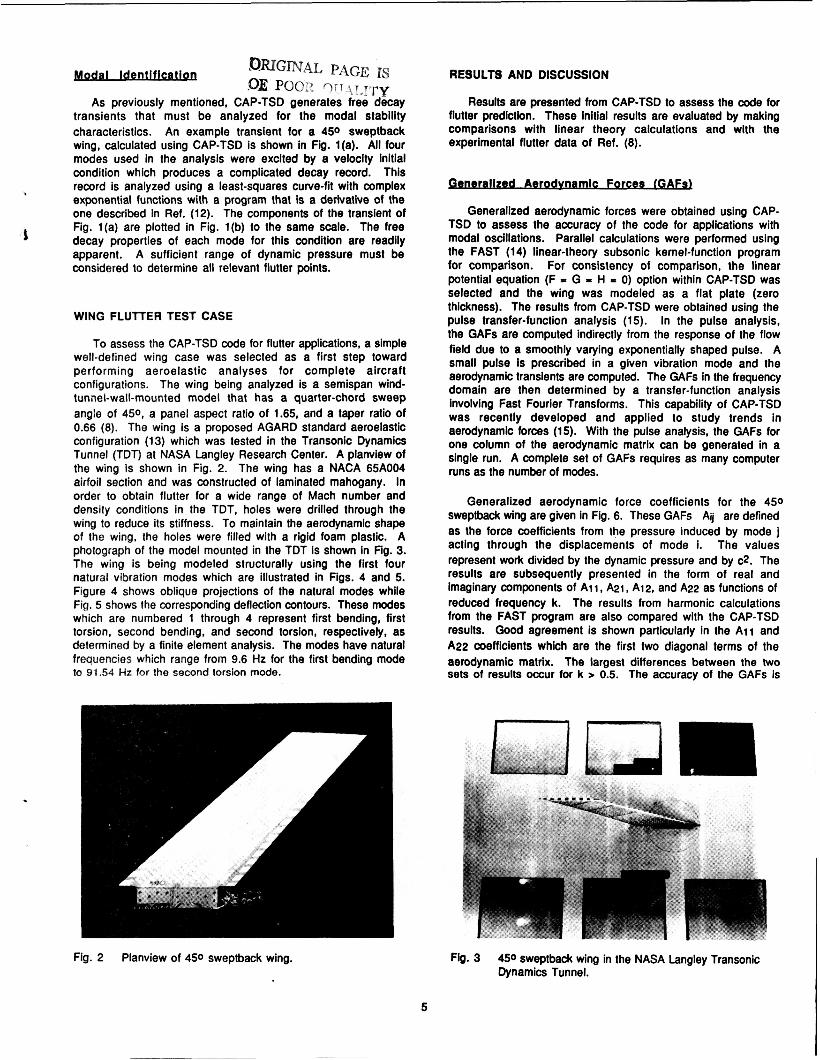
To assess the CAP-TSD code for flutter applications, a simple well-defined wing case was selected as a first step toward performing aeroelastic analyses for complete aircraft configurations. The wing being analyzed is a semispan wind- tunnel-wall-mounted model that has a quarter-chord sweep angle of 450, a panel aspect ratio of 1.65, and a taper ratio of 0.66 (8). The wing is a proposed AGARD standard aeroelastic configuration (13) which was tested in the Transonic Dynamics Tunnel (TDT) at NASA Langley Research Center. A planview of the wing is shown in Fig. 2. The wing has a NACA 65A004 airfoil section and was constructed of laminated mahogany. In order to obtain flutter for a wide range of Mach number and density conditions in the TDT, holes were drilled through the wing to reduce its stiffness. To maintain the aerodynamic shape of the wing, the holes were filled with a rigid foam plastic. A photograph of the model mounted in the TDT is shown in Fig. 3. The wing is being modeled structurally using the first four natural vibration modes which are illustrated in Figs. 4 and 5. Figure 4 shows oblique projections of the natural modes while Fig. 5 shows the corresponding deflection contours. These modes which are numbered 1 through 4 represent first bending, first torsion, second bending, and second torsion, respectively, as determined by a finite element analysis. The modes have natural frequencies which range from 9.6 Hz for the first bending mode to 91.54 Hz for the second torsion mode.
Fig. 2 Planview of 450 sweptback wing.
RESULTS AND DISCUSSION
Results are presented from CAP-TSD to assess the code for flutter prediction. These Initial results are evaluated by maklng comparisons with linear theory calculations and with the experimental flutter data of Ref. (8).
Aerodvmlc Forces IGAFa
Generalized aerodynamic forces were obtained using CAP- TSD to assess the accuracy of the code for applications with modal oscillations. Parallel calculations were performed using the FAST (14) linear-theory subsonic kernel-function program for comparison. For consistency of comparison, the linear potential equation (F I G = H - 0) option within CAP-TSD was selected and the wing was modeled as a flat plate (zero thickness). The results from CAP-TSD were obtained using the pulse transfer-function analysis (1 5). In the pulse analysis, the GAFs are computed indirectly from the response of the flow field due to a smoothly varying exponentially shaped pulse. A small pulse Is prescribed in a given vibration mode and the aerodynamic transients are computed. The GAFs in the frequency domain are then determined by a transfer-function analysis involving Fast Fourier Transforms. This capability of CAP-TSD was recently developed and applied to study trends in aerodynamic forces (15). With the pulse analysis, the GAFs for one column of the aerodynamic matrix can be generated in a single run. A complete set of GAFs requires as many computer runs as the number of modes.
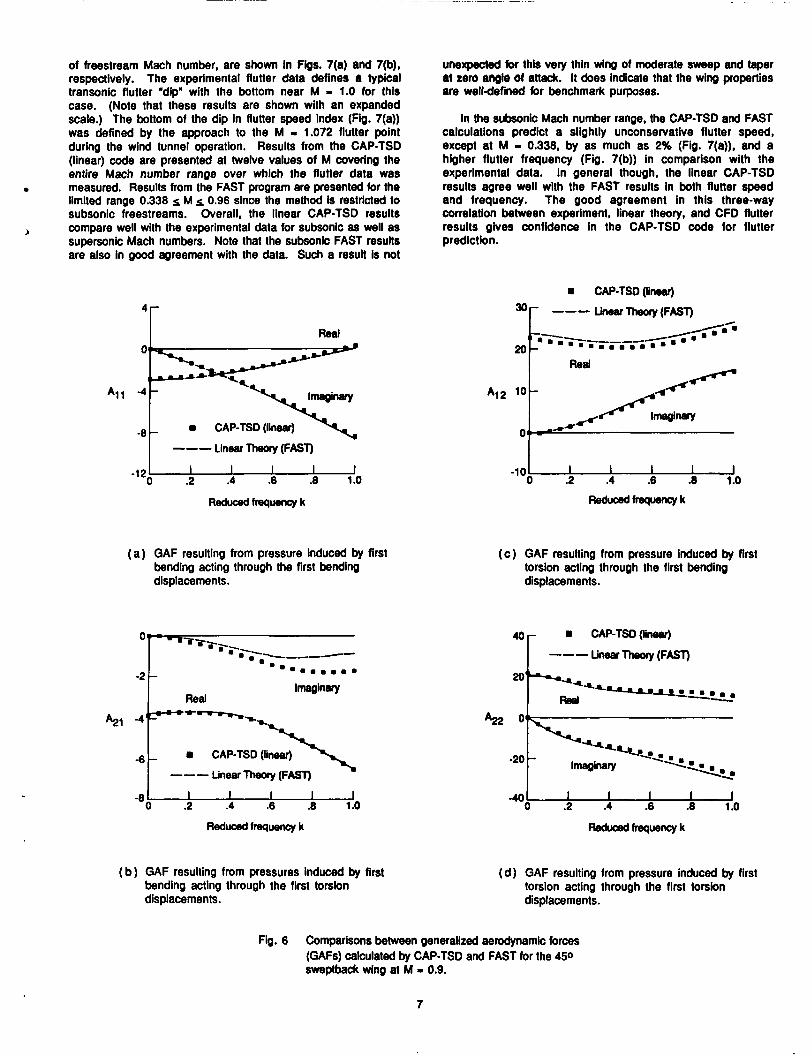
Generalized aerodynamic force coefficients for the 450 sweptback wing are given in Fig. 6. These GAFs Aij are defined as the force coefficients from the pressure induced by mode j acting through the displacements of mode i. The values represent work divided by the dynamic pressure and by c2. The results are subsequently presented in the form of real and Imaginary components of A i 1, A21, A12, and A22 as functions of reduced frequency k. The results from harmonic calculations from the FAST program are also compared with the CAP-TSD results. Good agreement is shown particularly in the A i 1 and A22 coefficients which are the first two diagonal terms of the aerodynamic matrix. The largest differences between the two sets of results occur for k > 0.5. The accuracy of the GAFs is
E
Fig. 3 450 sweptback wing in the NASA Langley Transonic Dynamics Tunnel.
5

ORIGINAL PAGe .oE POOR QUALITY
most important, however, for 0.1 k c 0.5, since this Is the range of reduced frequency where flutter typically occurs. The higher two modes, second bending and second torsion, have only a small Influence on flutter for this case. Although there are slightly larger differences between results for the higher modes (not shown), the GAFs from CAP-TSD agree well with those from FAST. This good agreement thus verifies the CAP-TSD d e for generalized force computation and indicates that the finite- difference grid is adequate for such applications.
E h m u m u a
Flutter calculations were performed for the 450 sweptback wing using CAP-TSD to assess the code for aeroelastic applications. Two sets of results are presented corresponding to:
(a ) Model,fl =9.60Hz
( b ) MOde2,12=38.17HZ
(1) using the linear potential equation and modeling the wing aerodynamlcally as a flat plate (zero thickness) and (2) using the complete (nonlinear) TSD equation and Including wing thickness. The first set of results allows for direct comparison wlth parallel linear theory calculations performed using FAST. The second set of results more accurately models the wing geometry as well as the flow physics. All of the results are compared wlth the experlmental flutter data of Ref. (8) which spans the range 0.336 s M s 1.141.
Comparisons of flutter characteristics from the linear calculations with the experimental data are given In Fig. 7. Plots of flutter speed index (defined as Ul(bo ma 6)) and nondlmenslonal flutter frequency (defined as dm) as functions
4
a (b) Mode2,12=38.17HZ
Fig. 4 Oblique projections of natural vibration modes of 450 sweptback wing.
Mode 3. I n = 48.35 HZ fl/
Fig. 5 Deflection contours of natural vibration modes of 450 sweptback wing.
6
of freestream Mach number, are shown in Figs. 7(a) and 7(b), respectively. The experimental flutter data defines a lypical transonic flutter ,dip" with the bottom near M I 1.0 for this case. (Note that these results are shown with an expanded scale.) The bottom of the dip in flutter speed index (Fig. 7(a)) was defined by the approach to the M I 1.072 flutter point during the wind tunnel operation. Results from the CAP-TSD (linear) code are presented at twelve values of M covering the entire Mach number range over which the flutter data was measured. Results from the FAST program are presented for the limited range 0.338 s M s 0.96 since the method Is restricted to subsonic freestreams. Overall, the linear CAP-TSD results compare well with the experimental data for subsonic as well as supersonic Mach numbers. Note that the subsonic FAST results are also In good agreement with the data. Such a result Is not
b
4r I Real
Linear Theory (FAST) I --- 1 -lzO .2 .4 .6 .8 1.0
Reduced freqwncy k
( a ) GAF resulting from pressure induced by first bending acting through the first bending displacements.
CAP-TSD (linear)
A21 -4
Linear Theory (FAST) -6
-8 4 .8 1.0 0 .2 .4 .6
Reducedfrequencyk
( b ) OAF resulting from pressures induced by first bending acting through the first torsion displacements.
unexpected for this very thin wing of moderate sweep and taper at zero angle of attack. It does indicate that the wing properties are well-defined for benchmark purposes.
in the subsonic Mach number range, the CAP-TSD and FAST calculations predict a slightly unconsewative flutter speed, except at M I 0.338, by as much as 2% (Fig. 7(a)), and a higher flutter frequency (Fig. 7(b)) in comparison with the experimental data. In general though, the linear CAP-TSD results agree well with the FAST results In both flutter speed and frequency. The good agreement in this three-way correlation between experiment, linear theory, and CFD flutter results gives confidence in the CAP-TSD code for flutter prediction.
CAP-TSD (linear)
Linear Theory (FAST)
- 1 0 2 0 .2 .4 .6 .8 1.0
M f r e q u e n c y k
( c ) GAF resulting from pressure induced by first torsion acting through the first bending displacements.
CAP-TSD(lineor)
Linear Theory (FAST)
I I I I I .2 .4 .6 .8 1.0
Reduced frequency k
(d ) GAF resulting from pressure induced by first torsion acting through the first torsion displacements.
Fig. 6 Comparisons between generalized aerodynamic forces (GAFs) calculated by CAP-TSD and FAST for the 450 sweptback wing at M = 0.9.
7

Comparisons of flutter characteristics from the linear and nonlinear CAP-TSD calculations with the experimental data are given in Fig. 8. Figure 8(a) shows flutter speed index versus Mach number and Fig. 8(b) shows nondimensionai flutter frequency versus Mach number. Three flutter points are pbtted from the nonlinear CAP-TSD calculations corresponding to M = 0.678. 0.901. and 0.96. Comparisons between the hno sets of CAP-TSD results show differences due to wing thickness and nonlinear effects. With increasing Mach number these differences become larger. For example, at M I 0.678, 0.901, and 0.96, the flutter speed index decreased by 1%. 5%, and 19%. respectively, as shown in Fig. 8(a). Similar decreases
e S 5 r
.so
.45
i& *40
.35
.30 L --- Linear Theory (FAST)
0 .2 .4 .6 .8 1.0 1.2 1.4
M
.25 L I I I I I I I
(a ) flutter speed index versus Mach number.
.’ r
8 CAP-TSD(linear)
--- LinearTheory (FAST)
.2 .4 .6 .8 1.0 1.2 1.4
M
( b ) nondimensionai flutter frequency versus Mach number.
Fig. 7 Comparisons between linear flutter caiculations with experimental data for the 450 sweptbedc wing.
also occur in the flutter frequency (Fig. 6(b)). The decrease in flutter speed at M I 0,901 is largely due to including wing tkldtness s i m lhm are no supersonic points in the flow at this condition. The decrease in flutter speed at M - 0.96 is attributed to both wing thickness and nonlinear effects since an embedded supersonic regbn of moderate site was detected in the wing tip region. The nonlinear CAP-TSD results at both M - 0.901 and 0.96 are slightly conservative In comparison with the experimental flutter speed index value. Nonetheless, the nonlinear CAP-TSD flutter results compare favorably with the experimental data, which is the first step toward validating the code for general transonic aeroelastic applicatbns.
t
.45
U bo”,J;; **
.35
.30 L 0 CAP-TSD(n0nli
0 .2 .4 .6 .0 1.0 1.2 1.4 M
25 1 I I I I I I I
(a ) flutter speed index versus Mach number.
r .6
.s 4L
.4 O0.
8 CAP-TSD(linearl
O CAP-TSD(rorJinear) .2
0 .2 .4 .6 .8 1.0 1.2 1.4
M
( b) nondimensbnal flutter frequency versus Mach number.
Fb. 8 Comparisons between linear and nonlinear CAP-TSD flutter predictions with experimental data for the 450 sweptback wing.
I 8

CONCLUDING REMARKS
The application and assessment of the recently-developed CAP-TSD (Computational Aeroelasticity erogram - Iransonic Small Disturbance) code for flutter prediction was presented and discussed. The CAP-TSD code has been developed for aeroelastic analysis of complete aircraft configurations in the flutter-critical transonic speed range. The code was previously applied to the calculation of steady and unsteady pressures on
Mach numbers. Comparisons of these results with other methods and with experimental data have been favorable. However, the purpose of CAP-TSD is for aeroelastic analysis. The evaluation and assessment of the CAP-TSD aeroelastic capability was the subject of the present study. Although the emphasis of the discussion was on CAP-TSD, the general computational procedures regarding time-marching flutter analysis apply to other computational fluid dynamics codes as well.
wings and configurations at subsonic, transonic, and supersonic
4
Generalized aerodynamic forces (GAFs) and flutter boundaries were presented for a 450 sweptback wing. The OAFS from CAP-TSD, calculated using the linear potential equation, agreed well with those from a linear-theory subsonic kernei- function program. This agreement thus verifies CAP-TSD for generalized force computation. The flutter boundaries from CAP-TSD (linear) were in agreement with parallel subsonic linear theory results and cornpared well with the experimental flutter data for subsonic and supersonic freestream Mach numbers. The nonlinear CAP-TSD flutter results also compared favorably with the experimental data which is the first step toward validating the code for general transonic aeroelastic applications.
REFERENCES
1. Edwards, J. W.; and Thomas, J. L.: 'Computational Methods for Unsteady Transonic Flows,' AIAA Paper No. 87- 0157, Presented at the A I M 25th Aerospace Sciences Meeting, Reno, NV, Jan. 12-15. 1987.
2. Borland, C. J.; and Rizzetta. D. P.: 'Nonlinear Transonic Flutter Analysis," AIAA u, vol. 20, Nov. 1982, pp. 1606- 1615.
3. Bendiksen, 0. 0.; and Kousen, K.: 'Transonic Flutter Analysis Using the Euler Equations," AlAA Paper No. 87-091 1. Presented at the AlAAlASMElASCElAHS 28th Structures, Structural Dynamics, and Materials Conference, Monterey, CA, April 6-8, 1987.
4. Wu. J. C.; Kaza, K. R. V.; and Sankar, N. L.: 'A Technique for the Prediction of Airfoil Flutter Characteristics in Separated Flows," AlAA Paper No. 87-0910. Presented at the AIANASMWASCUAHS 28th Structures, Structural Dynamics, and Materials Conference, Monterey, CA, April 6-8, 1987.
. *
5. Ballna, J. 1.: 'An Efficient Algorithm for Solutbn of the Unsteady Transonic Small-Disturbance Equation.' AlAA Paper No. St-OtW, h s e n t e d at the AlAA 25th Aerospace Sciences Meeting, Reno, NV. Jan. 12-15. 1987.
6. Batina, J. T.; Seidel, D. A.; Bland, S. R.; and Bennett, R. M.: "Unsteady Transonic Flow Calculations for Realistic Aircraft Configurations," AlAA Paper No. 87-0850. Presented at the AIANASMUASCUAHS 28th Structures, Structural Dynamics, and Materials Conference, Monterey, CA, April 6-8, 1987.
7. Bennett. R. M.; Bland, S. R.; Batina, J. T.; Gibbons, M. D.; and Mabey, D. 0.: 'Calculation of Steady and Unsteady Pressures on Wlngs at Supersonic Speeds with a Transonic Small- Disturbance Code,' AlAA Paper No. 87-0851. Presented at the AIANASMUASCElAHS 28th Structures, Structural Dynamics, and Materials Conference, Monterey, CA, April 6-8, 1987.
8. Yates, E. C., Jr.; Land, N. S.; and Foughner, J. T., Jr.: 'Measured and Calculated Subsonic and Transonic Flutter Characteristics of a 450 Sweptback Wing Planform in Air and in Freon-12 in the Langley Transonic Dynamics Tunnel,' NASA TN D-1616, March 1963.
9. Batina, J. T.: "Unsteady Transonic Algorithm Improvements for Realistic Aircraft Applications,' AlAA Paper No. 88-0105, to be presented at the AlAA 26th Aerospace Sciences Meeting, Reno. NV, January 11-14, 1988.
10. Edwards, J. W.; Bennett, R. M.; Whitlow, W., Jr.; and Seidel, D. A.: "Time-Marching Transonic Flutter Solutions Including Angle-of-Attack Effects,' JQJKMI of ALtcraft vol. 20, no. 11, Nov. 1983, pp. 899-906.
11. Edwards, J. W.; Bennett, R. M.; Whitlow, W., Jr.; and Seidel, D. A.: "lime-Marching Transonic Flutter Solutions Including Angle-of-Attack Effects,' AlAA Paper No. 82-3685, Presented at the AIAA/ASME/ASCUAHS 23rd Structures, Structural Dynamics, and Materials Conference, New Orleans, LA, May 10-12, 1982.
12. Bennett, R. M.; and Desmarais, R. N.: "Cunre Fitting of Aeroelastic Transient Response Data with Exponential Functions,' In 'Flutter Testing Techniques.' NASA SP-415, pp. 43-50, May 1975.
13. Yates. E. C., Jr.: 'AGARD Standard Aeroelastic Configurations for Dynamic Response. Candidate Configuration 1. - Wing 445.6," NASA TM 100492, August 1987.
14. Desmarais, R. N.; and Bennett, R. M.: "Useh Guide for a Modular Flutter Analysis Software System (FAST Version 1 .O),' NASA TM 78720, May 1978.
15. Mohr, R. W.: "Effects of Wing Geometry Variation on Transonic Aeroelastic Forces and Flutter Characteristics.' M.S. Thesis, Purdue Unhrersity, West Lafayette, Indiana, December 1987.
9

Report Documentation Page 1. Report No. 2. Government Accession No.
NASA TM-100531 4. Title and Subtitle
Modern Wing F l u t t e r Analys is By Computational F l u i d Dynamics Methods
7. Authorb)
H. J . Cunningham, J. T. Batina, and R. M. Bennett
9. Performing Organization Name and Address NASA Langley Research Center Hampton, V i r g i n i a 23665-5225
2. Sponsoring Agency Name and Address National Aeronautics and Space Admini s t r a t i o n Washington, DC 20546
5. Supplementary Notes
3. Recipient's Catalog No.
5. Report Date
January 1988 6. Performing Organization Code
8. Performing Organization Report No.
10. Work Unit No.
505-63-21-01 11. Contract or Grant No.
13. Type of Report and Period Covered
Technical Memorandum 14. Sponsoring Agency Code
This paper w i l l be presented a t t h e ASME Winter Annual Meeting, Boston, Massachusetts, December 13-18, 1987 as ASME Paper No. 87-WA/Aero-9.
6. Abstract
This paper describes the appl i c a t i o n and assessment o f t h e recently-developed The CAP-TSD code
Generalized aerodynamic forces and f l u t t e r c h a r a c t e r i s t i c s are
AP-TSD t ranson ic smal 1 -disturbance code f o r f l u t t e r p red ic t i on . as been developed f o r ae roe las t i c ana lys is o f complete a i r c r a f t con f i gu ra t i ons and 'as p rev ious ly app l ied t o the c a l c u l a t i o n o f steady and unsteady pressures w i t h avorable r e s u l t s . a l cu la ted and compared i n the present study w i t h l i n e a r theory r e s u l t s and w i t h xperimental data f o r a 450 sweptback wing. These r e s u l t s a re i n good agreement I i t h the experimental f l u t t e r data which i s t he f i r s t s tep toward v a l i d a t i n g CAP-TSD o r general t ranson ic ae roe las t i c app l i ca t ions . The paper presents these r e s u l t s anc omparisons along w i t h general remarks regard ing modern wing f l u t t e r ana lys is by omputational f l u i d dynamics methods.
7. Key Words (Suggested by Author(s)) I 18. Distribution Statement 'ransonic Unsteady Aerodynamics :omputational F1 u i d Dynamics , e r o e l a s t i c i t y l u t t e r
Unc lass i f i ed - Un l im i ted
Subject Category - 02 I
9. Security Classif. (of this report) 20. Security Classif. (of ths page)
l nc lass i f i ed Unc lass i f i ed 21. No. of pages I 22. Price
10 I A02 ~~
&SA FORM 1626 OCT 86