Embed Size (px)
Citation preview
/
NASA Technical Memorandum 109016
j-
AERODYNAMICS OF A SPHERE AND AN OBLATE SPHEROID
FOR MACH NUMBERS FROM 0.6 TO 10.5 INCLUDING SOME
EFFECTS OF TEST CONDITIONS
M. LEROY SPEARMAN
AND
DOROTHY O. BRASWELL
AUGUST 1993(NASA-TM-I0qoIb) AERODYNAMICS OF
SPHERE AN0 AN OBLATE SPHEROID FOR
MACH HU_BERS FROM 0.6 TO 10.5
[NCLUDING SOME EFFECTS OF TEST
CONDITIONS (NASA} 26 O
N94-13172
Uncles
G3/02 0181212
National Aeronautics andSpace Administration
Langley Research CenterHampton. Virginia 23681-0001
https://ntrs.nasa.gov/search.jsp?R=19940008699 2018-05-31T20:23:15+00:00Z
AERODYNAMICS OF A SPHERE AND AN OBLATE SPHEROIDFOR MACH NUMBERS FROM 0.6 TO 10.5 INCLUDING
SOME EFFECTS OF TEST CONDITIONS
M. Leroy SpearmanLangley Research Center
Hampton, Virginia
Dorothy O. BraswellLangley Research Center
Hampton, Virginia
Summary
Wind tunnel tests were made for spheres of various sizes and for anoblate spheroid over a range of Mach numbers and Reynolds numbers. Tests forthe oblate spheroid indicated drag values about 10 percent higher than that for asphere. The oblate spheroid results also indicated a region at high Machnumbers where inherent positive static stability might occur with the oblate-faceforward. Drag results from the present tests are compared with those for variousother shapes from other sources. The drag results for the sphere and the oblatespheroid were predicted accurately over the supersonic and hypersonic speedrange using impact methods.
The results indicated some conditions where the drag was affected bychanges in the afterbody pressure due to a shock reflection from the tunnel wall.This effect disappeared when the Mach number was increased for a givensphere size or when the sphere size was decreased for a given Mach number.Drag measurements and Schlieren photographs are presented that show thepossibility of obtaining inaccurate data when tests are made with a sphere toolarge for the test section size and Mach number.
Introduction
Blunt shapes are of interest for use as aerodynamic decelerators foraerobraking systems or as reentry vehicles. For such applications, the drag andstability characteristics must be determined for a wide range of operatingconditions. Past studies (references 1 to 5) point out some of the problems thatmay be encountered in determining the aerodynamics of sphere-like shapes.These problems are generally associated with unsteady flow conditions resultingfrom the blunt shapes. The past studies have included both free-flight tests andtests in wind tunnels. While both of these techniques are of value, it is believedthat wind-tunnel testing may provide for better control of test conditions. Theintent of the present paper is to supplement the aerodynamic data base forspheres and spheroids through the presentation of some previously unpublishedexperimental wind-tunnel results for such shapes over a Mach number range
from 0.6 to 10.5. In addition, the supersonic drag values are compared withvalues calculated by impact methods.
Symbols
A cross-sectional area at the maximum diameter
A c cross-sectional area of balance chamber
a.c. aerodynamic center location
CD drag coefficient, drag/qA
CDc balance chamber drag coefficient, (Pts - Pc ) Ac/qA
CLc ¢ lift curve slope
d diameter of sphere
M free-stream test section Mach number
Pc static pressure in balance chamber
Pts static pressure in test section
q free-stream dynamic pressure
R free-stream test section Reynolds number per foot
angle of attack, degrees
Models and Tests
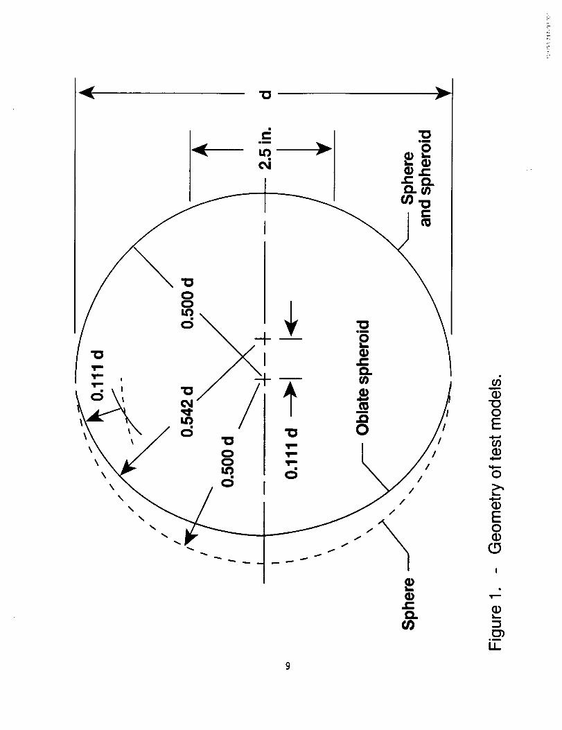
The geometry of the test models is shown in Figure 1. The sphere modelshad diameters of 6, 9, and 12 inches. The 6-inch oblate spheroid was derivedfrom the basic spherical shape but with the forward face blunted as indicated.Each model had a cutout in the rear to accommodate the housing for a strain-gage balance which, in turn, was mounted to a sting support strut. Severalstrain-gage balances were used in order to match the drag-beam load limit to theexpected drag level of the different models. Balance-chamber pressure wasmeasured by means of a single static-pressure orifice located in the balancechamber. The estimated accuracy of the drag coefficients is about 0.01 basedon repeatability of the data.
The angle of attack was corrected for deflection of the balance and stingdue to loads and for tunnel airflow angularity. The drag values were adjusted to
2
correspond to free-stream static pressure acting over the base cutout region.Tests of the spheres were made at zero angle of attack. Tests of the oblatespheroid were made at angles of attack from -4 to 10 degrees. Schlierenphotographs were made for most of the test runs.
The tests were made in three different wind tunnels at the LangleyResearch Center. Descriptions of these tunnels may be found in Reference6.Tests were made of the 6-inch sphere and oblate spheroid in the 8-FootTransonic Pressure Tunnel for Mach numbers from 0.60 to 1.20 at Reynoldsnumbers of 3.0 and 5.53 million per foot. The tunnel is a single-returnclosed-circuit type with a 7.1-foot square test section that is capable of providingcontinuous Mach numbervariations from 0.20 to 1.30.
Tests were made of each model in the Unitary Plan Wind Tunnel at Machnumbers from 1.50 to 4.63 for a Reynolds number range from 1.0 to 6.5 millionper foot. The tunnel is of the continuous-flow,asymmetric sliding-block type andthere are two test sections, each 4-feet square and 7 feet long. One test sectioncovers a Mach number range from 1.47 to 2.86 and the other, a Mach numberrange from 2.29 to 4.63.
Tests were made of the 6-inch sphere and oblate spheroid in theContinuous-Flow HypersonicTunnel in the continuous-flow mode at a Machnumber of 10.5 for Reynolds numbers from 0.2 to 1.0 million per foot. The tunnelis a variable-pressure, return-flowfacility with a 31-inchsquare test section. Thetest core is 14 inches square. Some limited results for a 3-inch and a 1-inchsphere at hypersonicspeeds are also included.
Presentationof Results
Figure
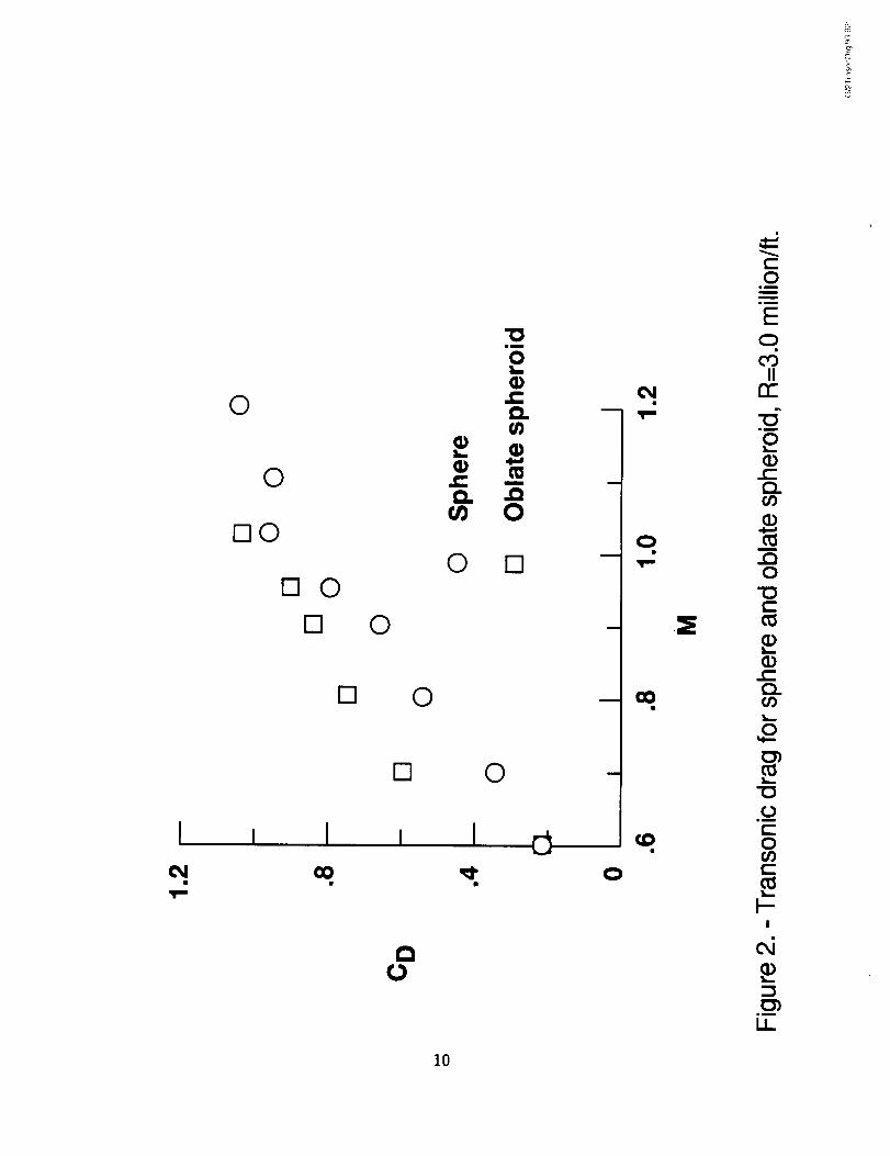
Transonic drag for sphere and oblate spheroid, R=3.0 million/ft....................... 2
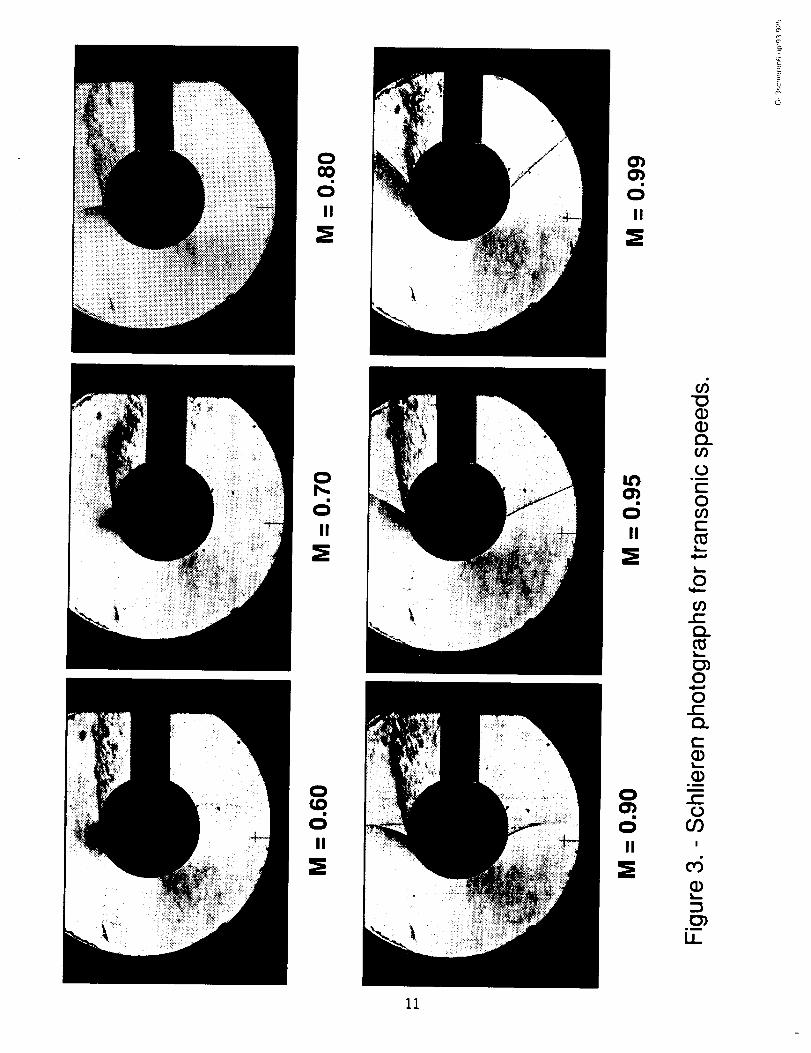
Schlieren photographs for transonic speeds .....................................................3
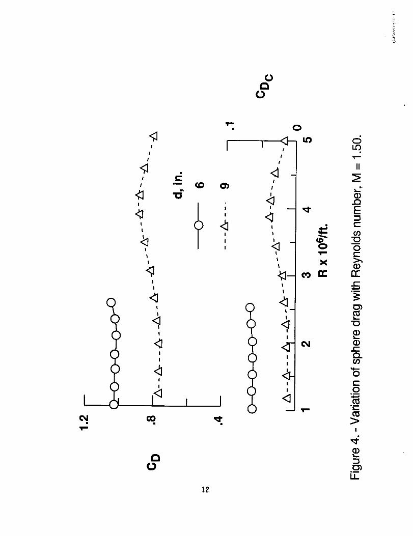
Variation of sphere drag with Reynolds number, M=1.50 .................................4
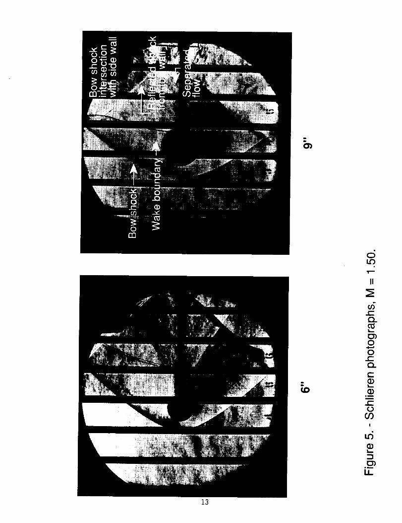
Schlieren photographs, M=1.50 ........................................................................5
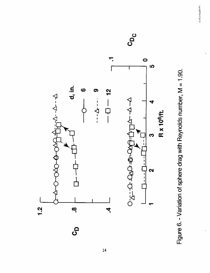
Variation of sphere drag with Reynolds number, M=1.90 .................................6
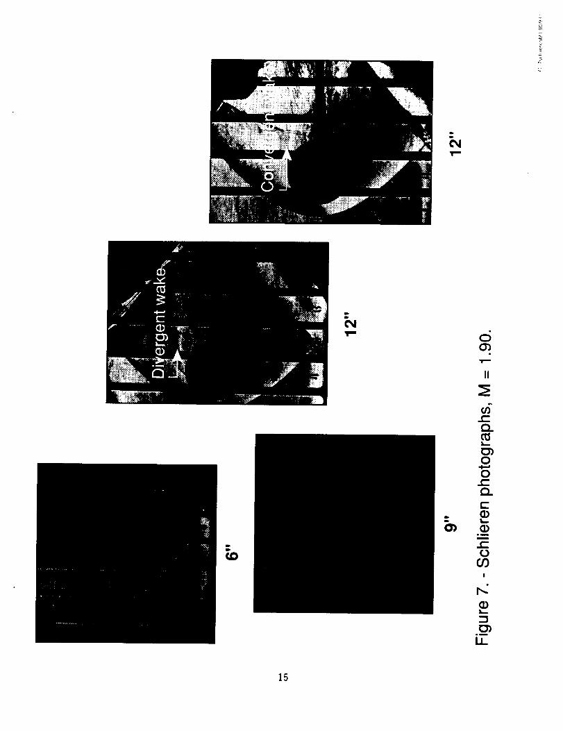
Schlieren photographs, M--1.90 ........................................................................7
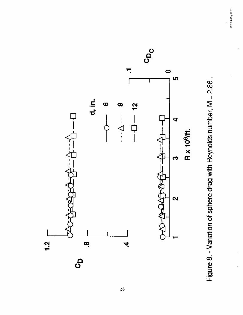
Variation of sphere drag with Reynolds number, M=2.86 .................................8
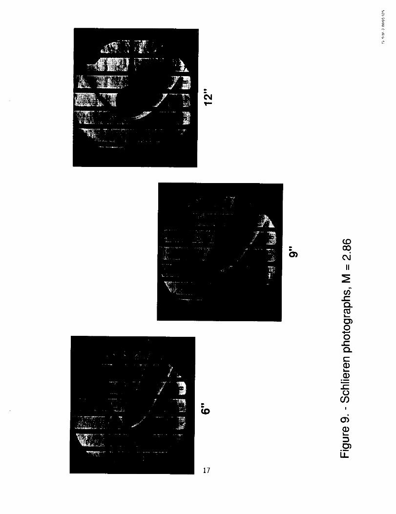
Schlieren photographs M=2.86 ......................................................................... 9
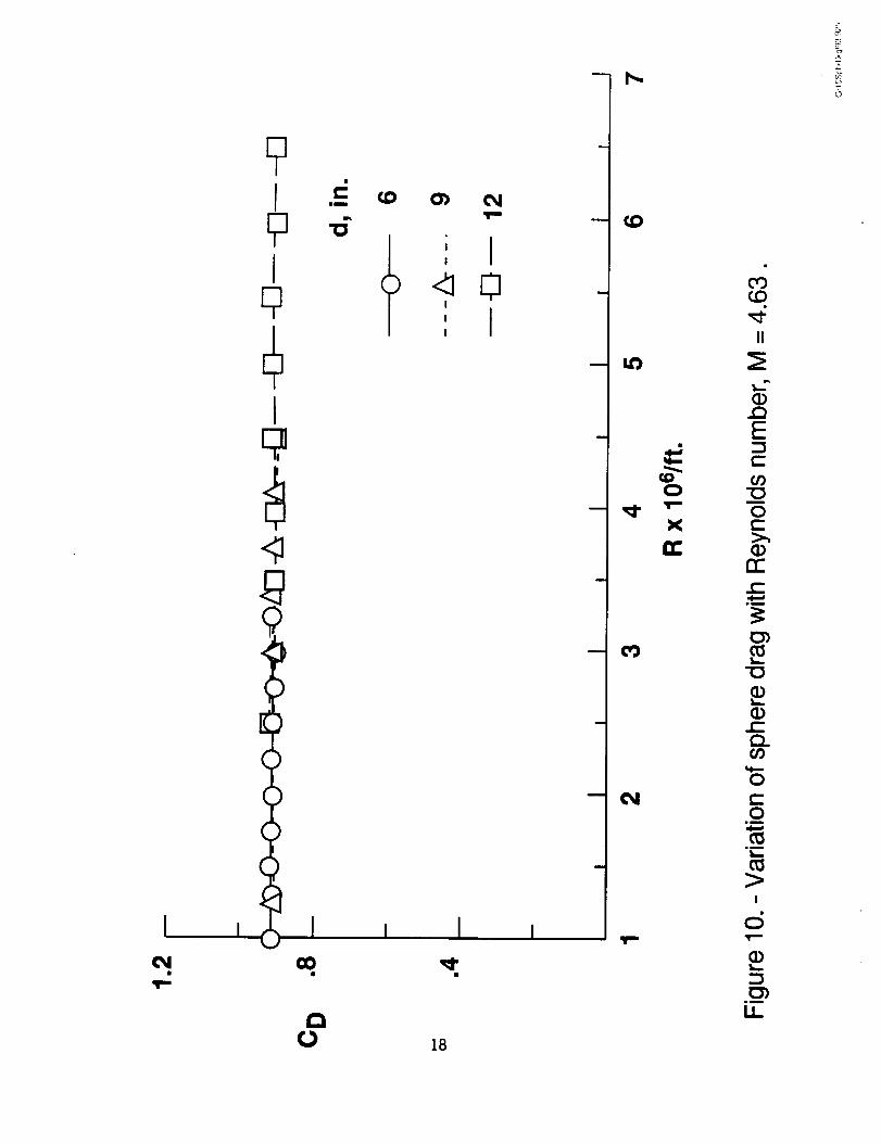
Variation of sphere drag with Reynolds number, M=4.63 ............................... 10
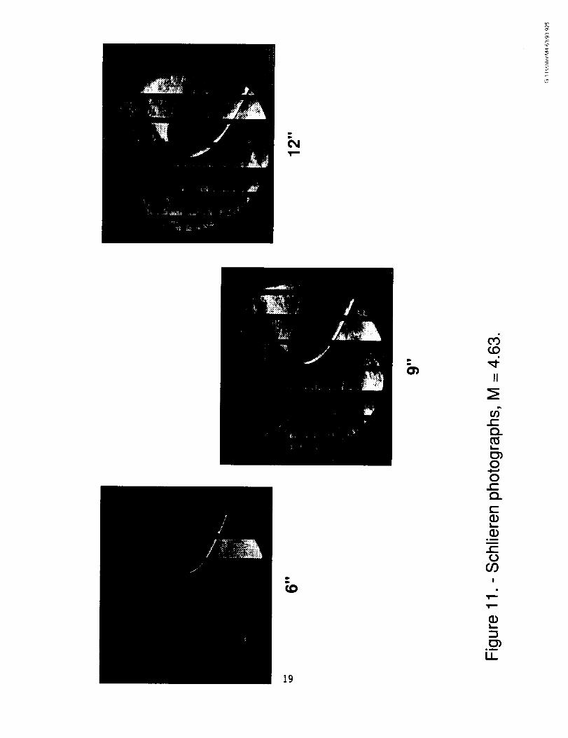
Schlieren photographs, M=4.63 ......................................................................11
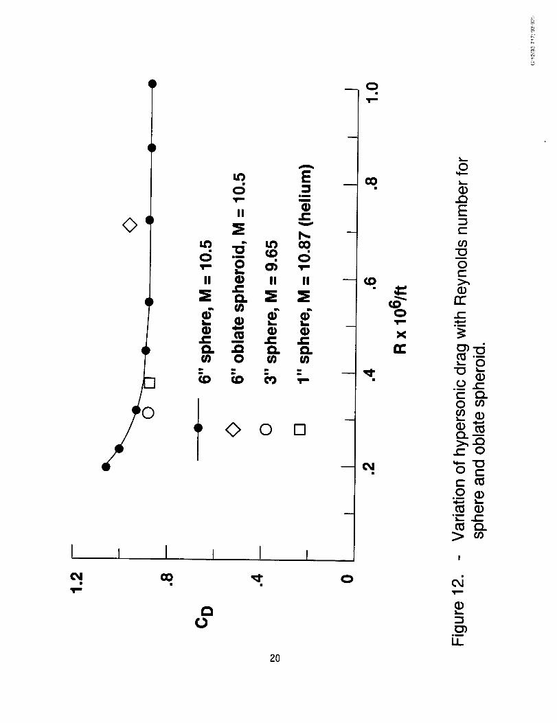
Variation of hypersonic drag with Reynolds number, sphere, and spheroid ... 12
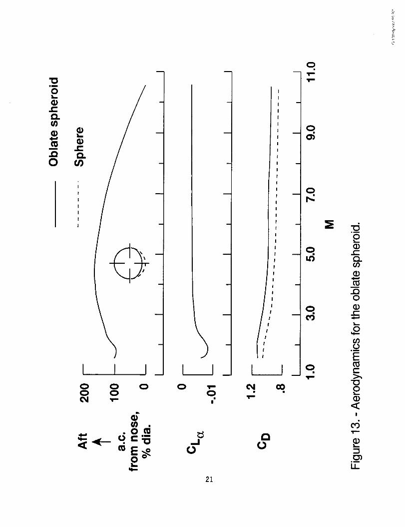
Aerodynamics for the oblate spheroid ............................................................. 13
Drag characteristics for various shapes .......................................................... 14
Comparison with Hoerner summary ................................................................ 15
Computer-generated drawings of the sphere and spheroid ............................ 16
Comparison with calculated results ................................................................. 17
Discussion
Transonic Results
The variations of drag with Mach number for the transonic tests arepresented in Figure 2 for the sphere and the oblate spheroid for a Reynoldsnumber of 3 million per foot. The drag results show a general increase withincreasing Mach number with the oblate spheroid producing the higher values.The drag variations are somewhat irregular because of the compressibility effectson the poorly streamlined shapes. Schlieren photographs (Fig. 3) show localsonic flow near the maximum diameter of the sphere at M=0.60 which isapproximately the critical Mach number for a sphere. The disturbance becomesmore pronounced with increasing Mach number. A local normal shock is wellestablished at M=0.80 and is coalesced into a supersonic shock on the model atM=0.95 The wake pattern for all of the transonic Mach numbers is divergent.
Supersonic Results
Effects of Sphere_ Size - The effects of sphere size at M =1.50 are presented inFigure 4 for a range of Reynolds numbers. The drag coefficients for the 9-inchsphere is substantially lower than that for the 6-inch sphere and the difference isreflected in the balance chamber drag coefficients. The reason for the differencecan be seen in the Schlieren photographs (Fig. 5). The reflection of the bowshock from the test section walls is very close to the rear of the model andcauses an increase in pressure at the model base that reduces the balancechamber drag coefficients. The flow field, as indicated in Figure 5, consists of thebow shock, the reflected shock from the top and bottom walls, the reflected shockwith the side wall, the separated flow field and the wake boundary. The reflectedshock, which can also be seen for the 6-inch sphere, is much further aft and hasno effect on the model base. The pressure differences at the rear of the modelsproduces wake patterns that are different - divergent for the 9-inch sphere and
4
slightly convergent for the 6-inch sphere. With the 12-inchsphere installed, itwas not possible to establish M=1.50 flow in the test section.
The effects of sphere size at M=1.90 (Fig. 6) indicategood agreement inthe drag coefficient values for the 6- and 9-inch models. The 12-inch modelindicates substantially lower drag coefficient values at the lower Reynoldsnumbers and a hysteresis effect near a Reynolds number of about 3 million perfoot where the drag results approach those for the two smaller models. Thedifferences are again seen in the balance chamber drag. The arrows on thefigure indicate the test sequence showing the hysteresis in the drag results.Schlieren photographs (Fig. 7) show that the reflected shock is well aft for the 6-and 9-inch models and the wake patterns are convergent for both models. Forthe 12-inch model, however, the reflected shock is close to the base and causes
an unsteady pressure field that randomly produces a convergent wake or adivergent wake.
The effects of sphere size for a Mach number of 2.86 are shown in Figure8. The drag coefficient results are similar for all three model sizes and thechamber drag is quite small. The Schlieren photographs (Fig. 9) indicate similarconvergent wake patterns for each model and the reflected shock is not visible.
The effects of sphere size for a Mach number of 4.63 are illustrated inFigure 10. The drag coefficient values are essentially the same for all threemodels and the balance chamber drag was negligible. The Schlierenphotographs (Fig. 11) show similar convergent wake patterns and the reflectedshocks are well downstream.
It is apparent from these results that, even though supersonic flow may beestablished in the test section, there are cases when the reflected shock from the
model may affect the pressure over the rear of the model and result in erroneousdrag values. Such conditions disappear, of course, as the model size isdecreased for a given Mach number or as the Mach number is increased for agiven model size.
Hypersonic Results
The variation of drag coefficient with Reynolds number for the hypersonictests (Fig. 12) show the drag level to be essentially invariant with Reynoldsnumber above about 0.5 million per foot. At lower Reynolds number it is believedthat the results are affected by tunnel blockage. This belief appearssubstantiated by the results shown from some unreported tests for smallerdiameter spheres. A single test point for the oblate spheroid at R=0.7 million perfoot indicates a slightly higher level of drag than that for the sphere.
5
Aerodynamics for the Oblate Spheroid
Some aerodynamic characteristics for the oblate spheroid are presented inFigure 13 for Mach numbersfrom 1.5to 10.5. The drag coefficient for the oblatespheroid decreasesvery slightly with increasing M as does that for the sphereand the values are about 10percent higher than for the sphere. The lift curveslope variation with M is similar to that for conventionalairfoils except for beinginverted. The negative lift curve slope results from the shape of the oblatespheroid. As the angle of attack is increased for this shape the curvature of theupper surface decreaseswhile the curvature of the lower surface increases.Thus the shape behaves like an inverted airfoil. The oblate shape also producesa pitching moment as the angle of attack is varied. The variations of lift andpitching moment with angle of attack were linear for the test range from -4 to 10degrees. By dividing the lift curve slope into the pitching moment curve slope,the aerodynamic center (a.c.) was determined and referenced to the nose of thebasic sphere. The a.c. variation with M thus obtained for the oblate spheroid isrearward up to about M=5 but then begins to move forward. In order to haveinherent static longitudinal stability when the lift curve slope is negative, it isnecessary that the a.c. be forward of the center of gravity. It is, therefore,interesting to note that, at the higher Mach numbers, it may be possible to attaininherent positive static stability with the oblate shape.
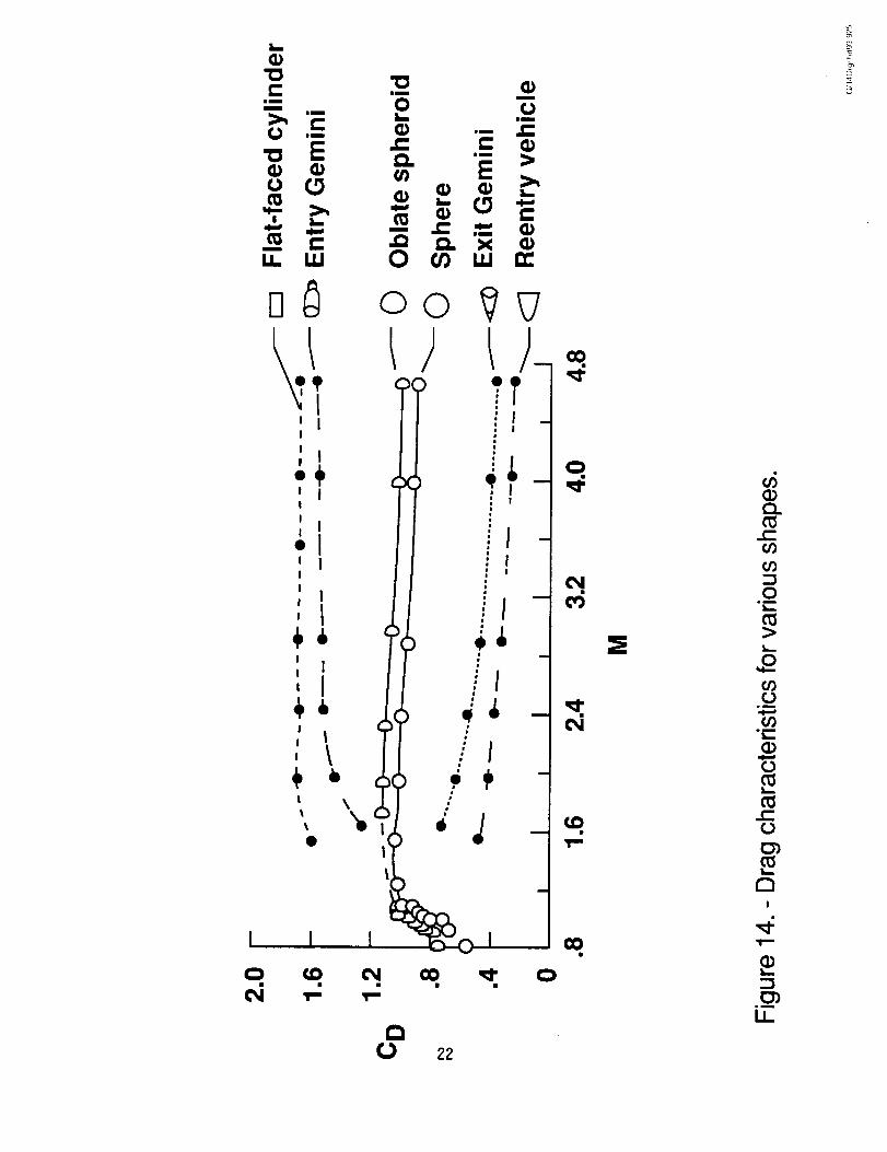
Effects of Shape
The variation of the drag coefficients with Mach number for the sphere andthe oblate spheroid are shown in Figure 14 for the transonic and supersonictests. The results indicate drag values for the oblate spheroid that are about 10percent higher than those for the sphere over the speed range. For comparison,the drag characteristics for various other shapes as obtained from someunpublished results from the Langley Unitary Plan Wind Tunnel at supersonicspeeds for a test Reynolds number of 2.5 million per foot are also presented inFigure 14. A flat-faced cylinder and a reentry Gemini capsule show substantiallyhigher drag than the sphere or the spheroid whereas a reentry shape and an exitGemini capsule have considerably lower drag.
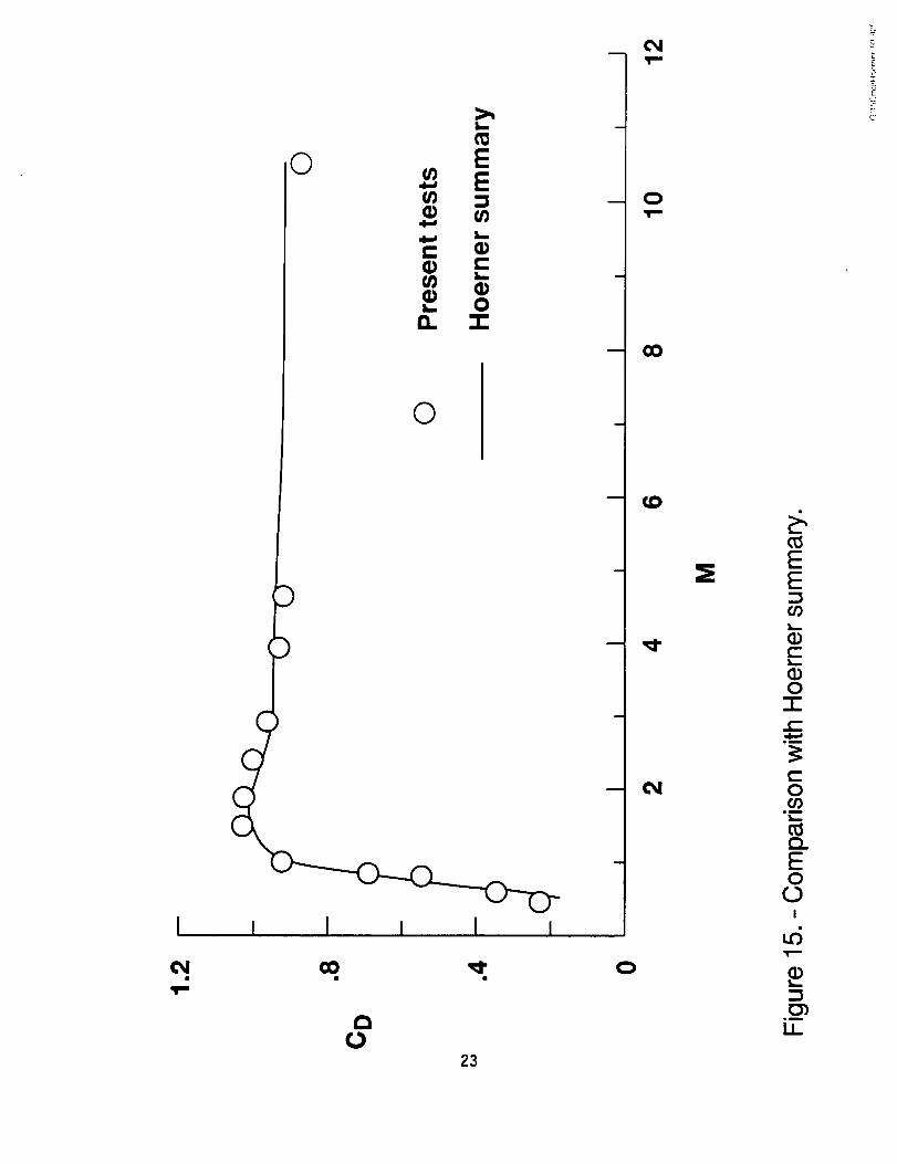
Comparisons with Other Results
- The experimental sphere drag results from the present tests arecompared in Figure 15 with a summary of sphere drag test results from a varietyof sources as compiled by Hoerner (Ref. 1). These data are for conditions abovethe critical Reynolds number. The comparison indicates close agreement andpresumably could be used to establish the level of sphere drag over the rangefrom subsonic speeds up to M=10.5.
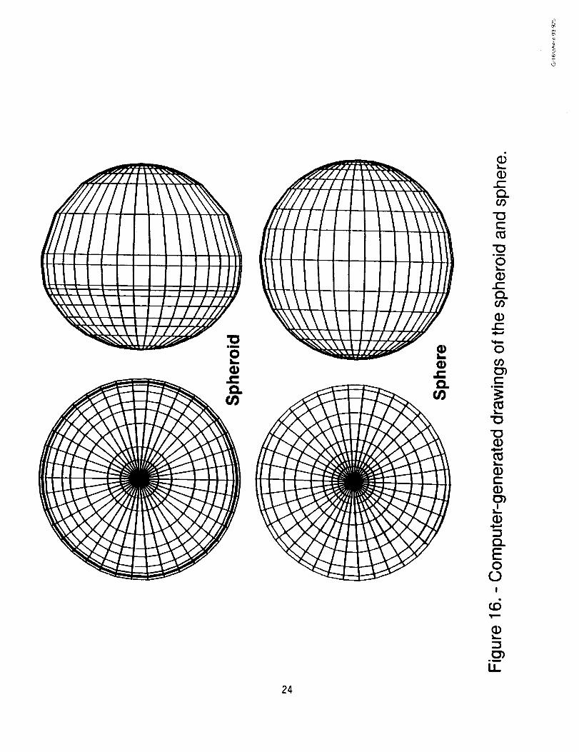
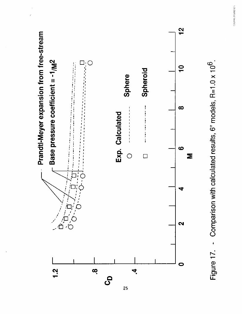
- The calculated drag results for the sphere and the oblate spheroidat supersonic and hypersonic speeds were obtained through the use ofReference 7. Computer-generated drawings of the sphere and the spheroid are
6
shown in Figure 16. The comparison of experimental and calculated drag resultsis presented in Figure 17. The drag in the impact region (forward face) wascalculated by use of the Modified Newtonian method for both the sphere and thespheroid. The drag in the shadow region (rear face) was calculated by twodifferent methods. One was the PrandtI-Meyer expansion from free-streammethod. The comparison is reasonably good - the Mach number trend beingessentially exact and the calculated values being only about 5 percent higher forboth the sphere and the spheroid. The second method used in the shadow
region assumed that the base pressure coefficient was equal to -1/M 2. Theseresults indicate almost exact agreement for the Mach number range from 1.90 to4.63 but the calculated results at M=10.5 were the same for both methods. Skin
friction values for all cases were calculated for a turbulent boundary layer by themethod of Spaulding and Chi.
Concluding Remarks
It has been the purpose of this paper to assess the aerodynamics of asphere and an oblate spheroid over a Mach number range from 0.60 to 10.5.Comparisons are made with results from various sources as well as with somecalculated results. Some concluding observations are:
• The results for an oblate spheroid indicated drag values about 10 percenthigher than those for a sphere.
• Results for the oblate spheroid indicated the possibility of attaininginherent positive static stability at high Mach numbers.
• The experimental drag results for the sphere were in good agreement withthe results from a variety of other experimental sources.
Calculated drag results for the sphere and the oblate spheroid indicatedgood agreement with the experimental values for the supersonic andhypersonic speed range.
• Erroneous drag values may be obtained if careful attention is not given tothe relation between model size and the test conditions.
o
2.
References
Hoerner, Sighard F.: Fluid-Dynamic Drag. Published by the Author, 1965.
Herrere, J. G.: Maximum Model-Size Determination and Effects of Sting
Diameter on an Entry Shape and Sphere for Low SupersonicMach-Number Testing. Technical Memorandum No. 33-191, JetPropulsion Laboratory, California Institute of Technology, Pasadena,California, October 30, 1964.
7
.
.
So
o
.
Charters, A. C.; and Thomas, R. N.: The Aerodynamic Performance ofSmall Spheres from Subsonic to High Supersonic Velocities. Journal of
Aeronautical Sciences, Vol. 12, No. 4, October 1945, Page 468.
Hodges, A. J.: The Drag Coefficient of Very High Velocity Spheres.Journal of Aeronautical Sciences, Vol. 24, No. 10, October 1957, Pages755-758.
Berger, E.; Scholz, D.; and Schumm, M.: Coherent Vortex Structures inthe Wake of a Sphere and a Circular Disk at Rest and Under Forced
Vibrations. Journal of Fluids and Structures, Vol. 4, May 1990, Pages231-257.
Schaefer, William T., Jr.: Characteristics of Major Active Wind Tunnels atthe Langley Research Center. NASA TM X-1130, 1965.
Gentry, A. E.: Vol. I-Users Manual. Gentry, A. E.; and Smyth, D. N.: Vol.II-Program Formulation and Listings. Hypersonic Arbitrary AerodynamicComputer Program (Mark III Version). Rep. DAC 61552, McDonnellDouglas Corp., April 1968. (Air Force Contract Nos. F33615 67 C 1008and F33615 67 C 1602.) (Available from DTIC as AD 851811 and AD861812.)
8
"13
"(3
\
d /\
\
\
\
ID
0,,
r_
Q_
1.1_
r_
0
0
nO
0 0
0
0
0
0
"0me
06
.C
.C --
0
0 0
n 0
I I I I I
0
0
oO
C0
INmn
O
or)IIrY-
-c:F5c--
or)
m
..C)0
O)
(I)(.-
or)
0
(.)IN
ell0or)(,..-
!
c',j
.-i
IN
U...
IO
0CO
0
II
:E
0
dII
=E
0¢JD
0
II
11
(2)
0
II
=E
W')
0
II
=E
00)
0
II
:E
"0(D
Q.cJo
(.-0
Cc_I,.-
0
(JO(.-Q_c_
0
0..CQ.
C
I,B
..CC.)
C_I
c_
1,m
0")
LI_
C,
0
0
I
C)
C
)
I
I
I
I
I
¢1I
I
|
I
I
I
I
I
I
I
I
I
I
I
I
0
12
I
I
I
I
I
C(
C()
I()
0
I
I
I
4 -I
I
I
<_| u
I
I
I
<_ -I
l
I
!
I
0
X
II
CD
E
n
0c->_
n-c-
_D
¢-Clu_
0
.m
>I
U_
O_j
LD(D
dt.O
.Tro-
ll
..CO.c_
00(--O.
(.-(1)L_
Q)
(-.(_
oO!
CD
0")on
LI_
!3
ii
<_I
I
<_I
I
<_
()
,I.==
I
I
I
I
I ,, I J IC'd GO
14
oa
0
0
m
-
9 I
!
It')
s(N==
0,N=..
X
_, [
0 -- _"
,Ni=
II
..QE"7{..-(I)
u
0¢-
c-
"0
c-O.
0
c-O
>I
.m
U_
a-
o
_2
b0)
6C_
II
(-.O_C_Im
0
0c-O_
im
CD
c-O
!
I,,B
Im
Ii
15
I
TI
DI
l
ii
l
!
: l
I
Oao
O
c_
O
X
_300
c_
H
c_Ee-
lOc-
¢-
"t3
c-Q.
O
Ul
!
t_gl
Li.
16
(N
II
0
0
r-
l--
I
Im
17
I
I9r
6
E
(
)
C)
()
C)
C
I () I
¢,D
I
: I
18
r,,,,
o
x
I1:
c.D
II
2_
Ef-
ff)"Om
0c-
o"
t3_
"t3
c"(3..
0
8.m
I
d
mB
Ii
S
o_
c_
,ira
r.D
DDCTJ
CD
H
c-O.
1in
C_0
.omw
0.CC1
C
in
!
mD
LL
19
I IO0
A
Eimm
II ._Z
IJD "1_ I_D O0• _Do "-^ d
II q) II II
s_ (1) s._ s_
4) "=' 4) 4)
0 E3
I
2O
_ 0
0
X
n-
m
m
0
0
(D.Q
E
r-
"O
0r-
rr
c-
-_•- 0
.0 t-r-- t-)o oo
>., ..Qi-" 0
_"'00 e'-
._0 _
•e- e-
ai
um
LI_
k
$
"¢3im
0!,_
cl)r..Q.¢n
cu4d
(0
.Q0
I,,,,
.C:Q.co
I I I_ I0 00 0
0 0
.0_
_EoO_s._
0|
21
I
I
#
I
I
I
I
I
I
I
I
I
I
I
I
I
I I
Qm
0m •
-b:
0
0
0
-d
e-
m
..Q0
(.-
0
E(-->.,
0
!
ed
gm
LI_
I
0
B_
ti I!
oo?_
I
_ ._ _i i!
Ii I.Ii II
!i I,!
!i I
, I
0i |! \
ID
\
÷t
I
u_(1)CL
(1(/)(/)
C).i
0
co0
(/)
a_
(II.(Z0
r_I
II
©
O
I i I i I i
23
O
¢O
Et./3
c'-
O-l-t,-
t-O
.D
EO
r,.3I
03
.m
Ii
a_
////Xli I\\\\\liJ'/?'i
,71////Illl ,l. ,Ittiii ii iiii i " '
N xx\. "=o
g
$_5
8_6
t__
.m
U_
24
i I I i
25
X
O.i
EO
O
O
I,.:
.m
Ii
REPORT DOCUMENTATION PAGE oM_ ,_ :_o._-o_F
.......: =" ........ " -* " -=" ....... ' .... ..... = .L._'.:::" .. : /,:.i. : :*__;..... _ii .._ :.'L'__--'-:; _.: -..: _:.: ..
1, AGENC _' USE ON.." :Leav_ _an,,, [ -, F,,_POKT D.-TE ] :., EEr-.O_,- "'_PE _r,,S DATES C._q,,'£F,ED
•[ August 1993 l Technical Memorandum_4. TITLEAND SUBTITLE
Aerodynamics of a SphereNumbers From 0.6 to 10.5Conditions
and an Oblate Spheroid for MachIncluding Some Effects of Test
6. AUTHOR(S)
M. Leroy Spearman and Dorothy 0. Braswell
7. PERFORMING ORGANIZATION NAME(S) AND ADDRESS(ES)
NASA Langley Research CenterHampton, VA 23681-0001
9.SPONSORING/MONITORINGAGENCY NAME(S)AND ADDRESS(ES)
National Aeronautics and Space AdministrationWashington DC 20546-0001
S FUNDING NLJMBERS
WU 505-69-20-01
8. PERFORMING ORGANIZATIONREPORT NUMBER
10. SPONSORING / MONITORINGAGENCY REPORT NUMBER
NASA TM-10g016
I1. SUPPLEMENTARY NOTES
Iaa.DISTRIRUTION/AVAI_BILITYSTATEMENT
Unclassified - Unlimited
Subject Category 02
12b. DISTRIBUTION CODE
! 13. ABSTRACT (Ma_mum 200 words)
Hind-tunnel tests were made for spheres of various sizes over a range of Machnumbers and Reynolds numbers. The results indicated some conditions where the dragwas affected by changes in the afterbodE pressure due to a shock reflection from thetunnel wall. This effect disappeared when the Mach number was increased for a givensphere size or when the sphere size was decreased for a given Mach number. Drag__asurements and Schlieren photographs are presented that show the possibility ofobtaining inaccurate data when tests are made with a sphere too large for the testsection size and Mach number.
Tests were also made of an oblate spheroid. The results indicated a region athigh Mach numbers where inherent positlve static stability might occur with theoblate-face forward. The drag results are compared with those for a sphere as wellas those for various other shapes. The drag results for the oblate spheroid and thesphere are also compared with some calculated results.
_a. su_tCT TERMSSphere; Drag;Blunt Bodies
|1
Spheroid; Aerodynamics; Decelerators; Aerobra kes;
17. SECURITY CLASSIFICATIONOF REPORT
UnclassifiedNSN 7540-01-2B0-5500
18. SECURITY CLASSIFICATIONOF THIS PAGE
Unclassified
lg. SECURITY CLASSIFICATIONOF ABSTRACT
Unclassified
1S. NUMBER OF PAGES
261G. PRICE CODE
A0320. LIMITATION OF ABSTRACT
Standard Form 29B (Rev. 2-8g)Pr_ by ANSI Std. Z39-10
298-102


![International spheroid[1]](https://img.pdfslide.us/doc/110x75/5447026db1af9fdc3a8b4784/international-spheroid1.jpg)