Embed Size (px)
Citation preview

National Aeronautics and Space Administration
NASA Sounding Rockets Annual Report 2016

2
Phil EberspeakerChief, Sounding Rockets Program Office
Mes
sage
from t
he
Chie
f
Another year has passed, and the NASA Sounding Rockets Program has once again completed a wide variety of impres-sive scientific, educational, and technology demonstration missions. We launched eight missions from sites in Norway, New Mexico and Virginia that carried science payloads to study the Earth's near space environment, deep space ob-jects, and our own local star, the sun. We also supported two student flight missions and three technology test flights to flight qualify new components and support systems offered to our customers. These new components and systems will enhance scientific return on future missions.
The missions we supported continue our long tradition of training the next generation of engineers and scientists. The instruments that were flown on our missions collected important scientific data that will help us better understand the Earth, the solar system, and the universe we live in. Our missions helped develop new detectors and instruments that will be applied to larger more sophisticated NASA missions. As an example, the Johns Hopkins Far-Ultraviolet Off-Rowland Telescope for Imaging and Spectroscopy (FORTIS) payload, which has also flown in previous years, validated the performance of a Micro Shutter Array (MSA) to be used on the massive James Webb Telescope, and the NextGenFOR-TIS instrument is currently under development and will test an even more advanced MSA with electronic shutters and other new technologies for future telescopes. Sounding rockets are the ultimate platforms for these types of continu-ous improvement projects, leading to overall efficiencies in the Nation’s space program.
The Sounding Rockets Program also made world-class sci-ence discoveries over the past year. Our geospace missions continued to collect data to better understand the Sun-Earth interaction and space weather. The University of Miami Dif-fuse X-ray emission from the Local Galaxy (DXL) mission collected critical data that has helped scientists solve the questions of the origins on X-rays emanating in the Local Hot Bubble (LHB) that was generated by multiple, ancient supernova explosions that occurred in our region of space.
The program once again push the boundaries of technol-ogy, not only for the program itself, but also for NASA as a whole. For example, we flew several technology demonstra-tion experiments for NASA's Space Technology Mission Directorate (STMD) Flight Opportunities Program (FOP). This included the RadPC, a computer system that uses a novel architecture and off-the-shelf parts to increase flight computer reliability in the presence of high-energy radia-tion at a fraction of the cost of existing rad-hard computer systems. Another technology involved the VIP, a vibration isolation platform which will be used to reduce spacecraft disturbances during microgravity. We engaged in numerous other technology development efforts to enhance data trans-mission rates, more precisely deploy sub-payloads, enable long range water recovery, and enable higher altitude flights. The program also continued its long tradition of training undergraduate and graduate students on our core science missions. Sounding rockets continue to be excellent plat-forms upon which graduate students can earn their PhD’s by participating as critical members of the PI’s science teams. Sounding rockets continue to serve as the perfect tool for teaching STEM education to undergraduates and other students. We once again flew two university level RockOn and RockSat-X missions which hosted over 100 student experimenters. We also continued our tradition of K-12 STEM education by offering multifaceted hands-on teacher workshops, lectures, school visits, and tours of our facilities.As I look back on our accomplishments over the past year I am once again impressed by the creativeness, dedication, and quality of our personnel. This not only includes technical staff, but also the business and administrative staff that make the program run so well and efficiently.
I am once again proud to lead this organization in providing NASA and the nation with low-cost, flexible access to space and I look forward to many more years of the Sounding Rockets Program serving the nation.
3
Table of ContentsMessage from the Chief 2
Sounding Rockets Overview 5Solar Physics Missions 2016 6
Extreme ultraviolet Variability Experiment (EVE) 8High Resolution Coronal Imager (Hi-C) 10
Astrophysics Missions 2016 12Planet Imaging Coronagraphic Technology Using a Reconfigurable Experimental Base (PICTURE-B) 14The Far-Ultraviolet Off-Rowland Telescope for Imaging and Spectroscopy (FORTIS) 15Diffuse X-rays from the Local Galaxy (DXL) 17Colorado High-resolution Echelle Stellar Spectrograph (CHESS) 19
Geospace Missions 2016 22Rocket Experiment for Neutral Upwelling (RENU 2) 24Cusp Alfven and Plasma Electrodynamics Rocket (CAPER) 25
Education Missions 2016 29RockOn! & RockSat-C 30RockSat-X 34
Technology and Special Projects Missions 2016 39Technology - Test and Support 40Multiple User Suborbital Instrument Carrier (MUSIC) 42Special Projects 43
STEM Education 45Wallops Rocketry Academy for Teachers and Students 46Internships and Outreach 47
Technology Development 49Water Recovery Shutter Door 51Clamshell Skin Development 51Free-Flying Ampule Development 52High Data Rate Encoder 52Upcoming Technology Development Flights 53Peregrine Static Firing 54Prototype Spin Motor 54Medium Mobile Launcher (MML) 55Side-Opening Vacuum Doors 55Manufacturing Cells 56
On the Horizon 59Kwajalein 2017 60Grand Challenge (GC) - Norway FY 2018 60Australia Campaign 62
Charts 64Mission Success History 64Sounding Rocket Vehicles 65Sounding Rocket Vehicle Performance 66Sounding Rocket Launch Sites 67Contact Information 68Sounding Rockets Program Office personnel 69

Technology
Vacuum Doors
Water Recovery
SUB-PAYLOAD development for SWARMS
Clam Shell Skin
Mobile LauncherThe Medium Mobile Launcher (MML) is the first launcher to be developed in-house by NSROC and is designed to launch vehicles as large as a Black Brant X (Terrier-Black Brant-Nihka) with a 1,000 pound payload.
Side-opening vacuum doors have been developed and tested to accommodate very large detectors requiring vacuum sealing for cleanliness.
New sub-payload systems have been developed for distributed measurements in space. To enable data collection over a larger area (volume) small rocket propelled sub-payloads are deployed to distances as far as 20 km from the main payload.
Telescope instruments are frequently reused after flight and to facilitate launches over water a new vacuum shutter door has been developed and tested. The new door will protect the instrument from saltwater after impact.
The Sounding Rockets Program Office (SRPO) and the NASA Sounding Rocket Operations Contract (NSROC) carry out NASA's sub-orbital rocket program. A fleet of vehicles acquired from military surplus or pur-chased commercially is used to carry scientific and technology payloads to altitudes between 50 and 1,500 kilometers. All payload support systems, such as Telemetry, Attitude Control, and Recovery are designed and fabricated by NSROC machinists, techni-cians and engineers. Launch operations are conduct-ed worldwide to facilitate science requirements, for example Geospace research is often conducted in the arctic from launch sites in Norway and Alaska. In-creasing mission complexities are addressed through continuous improvement in systems design and devel-opment.
Load bearing clamshell skin have been developed and flown. The new design is intended as a replacement for both long skirts and large deployable doors. By replacing a conventional skirt, the clamshell skin removes the chance of the skin touching the structure as it deploys. When used to replace a large blow-off door, the clamshell provides the structural support of a skin while allowing the same working volume as a blow-off door system.

Mis
sio
ns
Manufa
cturin
g
Integration and testing
Sounding Rockets Overview
Automated Inspection
Manufacturing Cells
Thirteen missions from three different launch sites, covering seven disciplines, were conducted in Fis-cal Year 2016.
The custom manu-facturing required for sounding rockets is enabled by state of the art machines and tooling. Efficiencies and throughput have been increased through the creation of manufactur-ing cells. This allows one machinist to operated several Computer Neumatic Control (CNC) machines simultaneously.
The increasing complexity of sounding rocket mission profiles and payload support system requirements leads to increasingly complex integration and testing processes. Mission profiles can involve deploying sub-payloads at specific intervals in specific directions at varying velocities. Payloads with multiple science instruments may require multiple Telemetry and Attitude Control Systems. In 2016 approximately twenty payloads were integrated and tested for flight.
Automated inspection of electrical components verifies assembly of cir-cuits prior to utilization in payloads.

6
304 Å: Emitted by helium-2 (He II) at
around 50,000 Kelvin. This light is emitted
from the chromosphere and transition
region.
211 Å: Emitted by iron-14 (Fe XIV) at
temperatures of 2,000,000 Kelvin. These
images show hotter, magnetically active
regions in the Sun’s corona.
193 Å: Emitted by iron-12 (Fe XII) at
1,000,000 Kelvin (hotter region of
the corona) and iron 24 (Fe XXIV) at
20,000,000 Kelvin (hotter material in
a flare). 94 Å: Emitt
ed by iron-18 (Fe XVIII) at tem
peratures of 6,000,000 Kelvin. Tem
peratures like this represent regions of the corona during a solar flare.
171 Å: Emitted by iron-9
(Fe IX) at around 600,000
Kelvin. This wavelength
shows the quiet corona
and coronal loops.
131 Å: Emitt
ed by iron-20 (Fe XX) and iron-23 (Fe XXIII) at tem
peratures greater than 10,000,000 Kelvin, representing the m
aterial in flares.
335 Å: Emitted by iron-16 (Fe XVI) at
temperatures of 2,500,000 Kelvin. These
images also show hotter, magnetically
active regions in the corona.
1700 Å: Ultraviolet light continuum, shows
surface of the Sun. As well as a layer of the Sun’s
atmosphere called the chromosphere, which lies
just above the photosphere and is where the
temperature begins rising.1700 Å
4,500 K
193 Å
1.6
mil K
211 Å
2 mil K
304 Å 50,000 K
335 Å~2.2 mil K
1600 Å10,000 K
13
1 Å
10
mil K
171 Å
~600,0
00 K
094 Å
6 m
il K
The 2016 Solar Physics Sounding Rocket missions focused on studying the sun in the Extreme Ultraviolet (EUV) part of the spectrum. The two missions included EUV Variability Experiment (EVE) and High Resolution Coronal Imager (HI-C). Extreme Ultraviolet radiation is created by very energetic processes occurring in several layers of the Sun. The Hi-C mission focused on the corona and the EVE mission was an underflight calibration of NASA’s Solar Dynamics Observatory (SDO) spacecraft.
Solar Physics Missions 2016
Convection Zone
Radiative Zone
Inner Core
Subsurface flows
Photosphere
Chromosphere
Corona
EVE
Credit: Multispectral background image NASA/SDO/GSFC Visualization Studio
Hi-C
1600 Å: Emitted by carbon-4 (C IV) at around 10,000 Kelvin. C IV at these temperatures is present in the upper photosphere and what’s called the transition region. The transition region is where the temperature rapidly rises.

7
Extreme ultraviolet Variability Experiment (EVE)
The EVE sounding rocket instrument is used for calibrating a similar instrument onboard the SDO spacecraft. The EVE sounding rocket is launched annually to enable correction of the satellite data. The SDO mission provides measurements and models of solar magnetic fields, active region dynamics, and the solar extreme ultraviolet (EUV) radiation that can dramatically disturb Earth’s space weather environment. EVE measures the solar EUV irradiance, the power per unit area (mW/m2), produced by the Sun in the form of electromagnetic radiation. Physics based models are used to advance the understanding of irradiance variations based on the activity of the solar magnetic features. EVE measures spectral irradiance at wavelengths of 0.1 - 1216 Å.
High Resolution Coronal Imager (Hi-C)
The main objective of the Hi-C investigation was to determine the geometric configuration and topology of the structures making up the inner corona. The mission was designed to study the mechanisms for growth, diffusion, and reconnection of magnetic fields, and the coupling of small-scale dynamic and eruptive processes to large-scale dynamics. Hi-C observations were coordinated with several NASA spacecraft. The scientific objectives of Hi-C are central to the goal of understanding the Sun’s activity and its effects on the terrestrial environment, by providing unique and unprecedented views of the dynamic activity in the solar atmosphere. Hi-C studied the sun at the 171 Å wavelength.
This plot of SDO EVE data shows time series of 5 strong EUV emission lines. Also shown is a Dark value, which is a detector that is blocked from seeing the Sun, which shows energetic particles from the Sun that can penetrate the EVE instrument and cause false counts. This Dark diode will increase during solar storms
Top - HI-C image from the 2012 sounding rocket flight. Bottom - the same region imaged with SDO Atmospheric Imaging Assembly.
Electromagnetic Radiation
Most of the radiation emitted by the Sun is blocked by the Earth’s atmosphere. In order to study the Sun at these wavelengths, instruments have to be placed in space. Spacecraft such as the Solar Dynamics Observatory (SDO) include multispectral instruments and have mission durations of several years. Sounding rockets are used for both fundamental science exploration and development of future technologies for spacecraft. With short mission lead times and lower cost, sounding rockets enable world class science discovery.
Instruments for Solar Physics
Spectrographs are commonly used instruments for solar physics. A spectrograph measures radiation intensity as a function of wavelength. All elements
in the periodic table have associated characteristic spectra. When energy is added to an element, i.e., when electrons in an atom are excited and then transition back from this excited state to their
ground energy levels, they emit radiation at specific wavelengths. Scientists have cataloged spectral wavelengths of the elements and use that information to determine the presence of these elements in the Sun and other stars. Elements found on the Sun, using spectroscopy, include hydrogen and helium
with smaller amounts of other elements such as carbon, nitrogen, oxygen, neon, magnesium, silicone, sulfur, and iron.
Knowing which elements are present, and their ionization temperatures, allows scientists to determine the temperature of the various regions of the Sun. To ionize an atom, enough energy has to be added to
free electron(s) from the atom. For example, to ionize iron, which in its neutral state has 26 electrons (Fe I), temperatures around one
million Kelvin are required. When the iron atoms encounter these temperatures eight or nine of the electrons are freed and ions of Fe
IX and Fe X are created and EUV radiation at a wavelength of 171 Å is emitted.
Part of a solar ultraviolet emission line spectrum was obtained with NASA's Solar Extreme-ultraviolet Research Telescope and Spectrograph (SERTS) sounding
rocket experiment. Wavelength increases from 300 Å on the far left to 350 Å on the far right. The graph in the bottom frame is a different way to show how bright
the lines are at each different wavelength. Intensity, how bright the line is, in the y-axis, and wavelength is in the x-axis. The most prominent lines are labelled with their
respective elements.Credit: Dr. Jeffrey Brosius/NASA GSFC
Si X
I He
II
Fe X
VFe
XV
II
8
Ext
rem
e ult
ravi
ole
t Va
riability
Exp
erim
ent
(EVE)
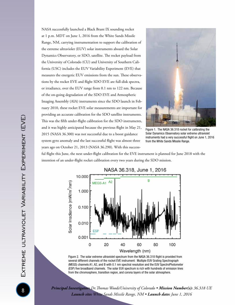
Principal Investigator: Dr.Thomas Woods/University of Colorado • Mission Number(s): 36.318 UELaunch site: White Sands Missile Range, NM • Launch date: June 1, 2016
NASA successfully launched a Black Brant IX sounding rocket
at 1 p.m. MDT on June 1, 2016 from the White Sands Missile
Range, NM, carrying instrumentation to support the calibration of
the extreme ultraviolet (EUV) solar instruments aboard the Solar
Dynamics Observatory, or SDO, satellite. The rocket payload from
the University of Colorado (CU) and University of Southern Cali-
fornia (USC) includes the EUV Variability Experiment (EVE) that
measures the energetic EUV emissions from the sun. These observa-
tions by the rocket EVE and flight SDO EVE are full-disk spectra,
or irradiance, over the EUV range from 0.1 nm to 122 nm. Because
of the on-going degradation of the SDO EVE and Atmospheric
Imaging Assembly (AIA) instruments since the SDO launch in Feb-
ruary 2010, these rocket EVE solar measurements are important for
providing an accurate calibration for the SDO satellite instruments.
This was the fifth under-flight calibration for the SDO instruments,
and it was highly anticipated because the previous flight in May 21,
2015 (NASA 36.300) was not successful due to a boost guidance
system gyro anomaly and the last successful flight was almost three
years ago on October 21, 2013 (NASA 36.290). With this success-
ful flight this June, the next under-flight calibration for the EVE instrument is planned for June 2018 with the
intention of an under-flight rocket calibration every two years during the SDO mission.
Figure 1. The NASA 36.318 rocket for calibrating the Solar Dynamics Observatory solar extreme ultraviolet instruments had a very successful flight on June 1, 2016 from the White Sands Missile Range.
Figure 2. The solar extreme ultraviolet spectrum from the NASA 36.318 flight is provided from several different channels of the rocket EVE instrument: Multiple EUV Grating Spectrograph (MEGS) channels A1, A2, and B with 0.1 nm spectral resolution and the EUV SpectroPhotometer (ESP) five broadband channels. The solar EUV spectrum is rich with hundreds of emission lines from the chromosphere, transition region, and corona layers of the solar atmosphere.
9
The mission principal investigator Tom Woods, from the University of Colorado at Boulder, reports that these
under-flight data are excellent and are one of the highest quality measurements due to lower noise from the
cooled CCD sensors than previous flights. The solar EUV irradiance spectrum from this flight is shown in
Figure 2. In addition to updating the calibration for the SDO satellite instruments, this rocket measurement
is also valuable for the broader solar international community because this rocket measurement will validate
solar EUV observations from NASA Solar Terrestrial Relations Observatory (STEREO), NASA Solar Radiation
and Climate Experiment (SORCE), NASA Thermosphere Ionosphere Mesosphere Energetics and Dynamics
(TIMED), NASA/ESA Solar and Heliospheric Observatory (SOHO), NASA/JAXA Hinode, NOAA Geosta-
tionary Operational Environmental Satellites (GOES), and ESA Proba2 missions.
The web links for SDO EVE and LASP rocket programs are:
http://lasp.colorado.edu/home/eve/
http://lasp.colorado.edu/home/missions-projects/lasp-rockets/current-launch-status/
Principal Investigator: Dr.Thomas Woods/University of Colorado • Mission Number(s): 36.318 UELaunch site: White Sands Missile Range, NM • Launch date: June 1, 2016

10
Hig
h R
esolu
tion
Corona
l Im
ager
(Hi-C
)
Principal Investigator: Dr. Jonathan Cirtain/NASA Marshall Space Flight Center • Mission Number(s): 36.314 NS Launch site: White Sands Missile Range, NM • Launch date: July 27, 2016
The High-resolution Coronal Imager (Hi-C)
mission flew for the second time in 2016.
Hi-C is designed to capture the highest-
resolution images of the sun’s million-degree
atmosphere, called the corona, in the extreme
ultraviolet wavelength. This higher energy
wavelength of light is optimal for viewing the
hot solar corona.
The science goal of the second flight was to
identify the connection between the solar
chromosphere, transition region, and corona
in the hottest and most active regions of the
corona. To meet this science goal, the high
resolution coronal images from Hi-C would
be combined with data from the Interface Re-
gion Imaging Spectrograph (IRIS), the Solar
Dynamics Observatory Atmospheric Imaging
Array (AIA) and Helioseismic Magnetic Im-
ager (HMI) and the instruments on the Hinode spacecraft. Additionally, the mission was designed to study the
mechanisms for growth, diffusion, and reconnection of magnetic fields of the corona, and to help understand
the coupling of small-scale dynamic and eruptive processes to large scale dynamics.
Hi-C was a pathfinder mission designed to place significant new limits on theories of coronal heating and
dynamics by measuring the structures at size scales relevant to reconnection physics. The Hi-C instrument used
normal-incidence EUV multilayer technology, as developed in the Normal Incidence X-ray Telescope (NIXT)
and Transition Region And Coronal Explorer (TRACE) programs. A dual-channel long focal-length telescope
and large format back-illuminated CCD camera provided spectroscopic imaging of the corona at 0.3 arcsec
resolution.
Due to a failed electrical connection, the instrument shutter did not open in flight and science data was not
collected.
Patrick Champey (University of Alabama – Huntsville graduate student), Richard Gates and William Podgorski (Smithsonian Astrophysical Observatory) complete an alignment procedure on the Hi-C instrument in a clean room at the National Space Science Technology Center in Huntsville, Alabama, prior to shipping to White Sands Missile Range in New Mexico for its July 19, 2016, launch.

11Setting up to align the Solar Pointing Attitude Rocket Control System (SPARCS).

12
Astrophysics seeks to understand the universe and our place in it and aims to discover how the universe works, explore how it began and evolved, and search for life on planets around other stars.
Spectrometers and telescopes are frequently flown onboard sounding rockets for Astrophysics research. Telescopes focus the incoming radiation from a target object and spectrometers spread light out into specific wavelengths creating a spectra.
All atoms and molecules have characteristic spectra that produce absorption or emission lines at specific wavelengths. This allows scientists to get information about composition, temperature, and other variables of the astronomical target of their study.
Emission line spectra are created when an electron drops down to a lower orbit around the nucleus of an atom and loses energy. Absorption line spectra occur when electrons move to a higher orbit by absorbing energy.
The Far-Ultraviolet Off-Rowland Telescope for Imaging and Spectroscopy (FORTIS)
FORTIS is an innovative, multi-object, far-Ultraviolet (UV) spectro/telescope that splits the light from the target galaxy into its composite wavelengths. How much of each wavelength is present holds clues to the atoms present in the space through which the light is traveling. Scientists studied the wavelengths of energy emitted and absorbed by different types of hydrogen to quantify how much material is flowing in and out of the target galaxy NGC 1365, the Great Barred Spiral Galaxy.
Planet Imaging Concept Testbed Using a Rocket Experiment (PICTURE)
The goal of this mission was to obtain a direct image of a planetary environment around another star, Epsilon Eridani (ε Eri). ε Eri contains at least one planet and a substantial dust disk, discovered around the star in 1998. The primary goal of PICTURE was to directly image this inner 3 AU dust belt in reflected visible light. This would provide a measurement of the dusty background to help guide future attempts to image the planet.
Astrophysics Missions 2016

13
Visible light is what we are most familiar with on Earth. Visible light ranges in wavelength from 400 nm to 700 nm, with violet being the shortest wavelength and red the longest. Absorption and emission
spectra of objects in the Universe reveal information about the elements present, the temperature, and density of those elements and the presence of a magnetic field and many other variables. Continuos spectra are created by hot opaque objects.
An absorption spectrum is created when energy from a hot opaque object travels through cooler transparent gas.
Hot transparent gas, such as gaseous nebulae, create emission spectra.
High energy and high temperature processes in the Universe radiate in the Ultraviolet part of the spectrum. Knowledge of star formation and evolution, growth
of structure in the Universe, physics of jet phenomena on many scales, aurora on and atmospheric composition of the gas giant planets, and of the physics of protoplanetary
disks has been expanded through UV observations.
To emit X-rays, gas must be under extreme conditions, such as temperatures of millions of degrees, superstrong magnetic fields, or electrons must be moving at nearly the speed of
light. Extreme conditions can be found in disks of matter orbiting black holes or in supernova remnants. Strong magnetic fields, like those created in the wake of a supernova explosion, can
also accelerate fast moving ions in spirals around the field lines to the point of X-ray emission. X-rays are classified into two types: soft X-rays and hard X-rays. Soft X-rays fall in the range of the EM spectrum
between (UV) light and gamma-rays. Soft X-rays have relatively short wavelengths — about 10 nanometers (nm), to about 100 picometers (pm). Hard X-rays have wavelengths of about 100 pm to about 1 pm and are very close to
gamma-rays. The only difference between them is their source: X-rays are produced by accelerating electrons, while gamma-rays are produced by atomic nuclei.
Colorado High-resolution Echelle Stellar Spectrograph (CHESS) 2
CHESS studied translucent clouds in the interstellar medium (ISM). CHESS allowed measurement of the composition, motion and temperature of this interstellar material in unprecedented detail. CHESS also took a snapshot of the raw materials available that were needed to develop planets, such as, carbon, nitrogen, and oxygen. High-resolution absorption line spectroscopy when looking toward hot stars, such as ε Persei (epsilon Persei) the target for CHESS, provides a rich set of diagnostics with which to simultaneously measure the temperature, composition, and velocity fields of the solar neighborhood.
Diffuse X-rays from the Local Galaxy (DXL)
DXL studied the irregularly shaped cavity, the Local Hot Bubble (LHB) filled with X-ray-emitting hot gas. These X-ray emissions have long been thought to originate from remnants of supernovae which formed the local hot bubble. The first flight of DXL, in 2012, found that around 40 percent of this radiation is a result of the Solar Wind Charge Exchange (SWCX) i.e. solar wind stripping away electrons from neutral gas in space and emitting X-rays. The purpose of the 2016 flight was to better understand the nature and characteristics of the local hot bubble, the solar wind charge exchange, and their fundamental physics. Results from this flight will improve modeling capability of X-ray data for past, present, and future missions.
Hydrogen absorption spectra in visible wavelengths.
Hydrogen emission spectra in visible wavelengths.
Electromagnetic Radiation

14
Pla
net
Imag
ing C
orona
gra
phic
Tec
hno
logy
Usi
ng a
Rec
onfi
gura
ble
Exp
erim
enta
l Bas
e (P
ICTU
RE-B
)
Principal Investigator: Dr. Supriya Chakrabarti/University of Massachussetts - Mission Number(s): 36.293 UG Launch site: White Sands Missile Range, NM - Launch date: November 25, 2015
The PICTURE-B (36.293) sounding rocket mission was designed to directly image the exozodiacal dust and
debris disk around the Sun-like star Epsilon Eridani. In addition to the science contributions of PICTURE-
B, the mission also matured essential technology for the detection and characterization of visible light from
exoplanets for future larger missions currently being imagined. These technologies include: an ultralight-weight
0.5 m diameter silicon carbide primary mirror, a wavefront control system that uses a 32x32 element MEMS
deformable mirror (DM), a milliarcsecond pointing control system, and the heart of the PICTURE instrument,
the Visible Nulling Coronagraph (VNC, nuller). The VNC attenuates the overwhelmingly bright light from a
star, while enabling dim light from material around the star (dust and planets) to reach the science camera. The
electronics section on PICTURE-B includes three networked computers controlling the nuller, the science and
wavefront sensing cameras, and the fine pointing system.
The experiment was launched from the White Sands Missile Range in New Mexico on November 24, 2015 and
demonstrated the first space operation of a nulling coronagraph and a deformable mirror. Regrettably, the ex-
periment did not achieve null due to a slight shift in the deformable mirror position on launch. Because of this,
it did not return any science results. The fine pointing system performed extremely well, optically stabilizing the
pointing to between 3 and 5 milliarcseconds. The wavefront control system successfully sensed the wavefront at
the required precision of 1 nm RMS.
The next generation PICTURE-C mission has been selected by NASA to fly aboard a high-altitude balloon in
2017 and 2019.
Electronics Instrument Telescope

15
The
Far-U
ltra
viole
t Off
-Rowla
nd T
eles
cope
for Imag
ing a
nd S
pec
trosc
opy
(FORTIS)
Principal Investigator: Dr. Stephan McCandliss/Johns Hopkins University - Mission Number(s): 36.312 UG Launch site: White Sands Missile Range, NM - Launch date: December 18, 2015
The Far-Ultraviolet Off-Rowland Telescope for Imaging and
Spectroscopy (FORTIS 36.312) launched from the White Sands
Missile Range in New Mexico to investigate the properties of galaxy
NGC 1365, also known as the Great Barred Spiral Galaxy. FORTIS
aimed to contribute knowledge to one of the remaining mysteries
about the evolution of the universe, namely, how did it get reion-
ized about 400 million years ago.
FORTIS has a multi-object spectroscopic capability between 800
- 2000 Å and an imaging bandpass of 1300 - 2000 Å and uses a
novel prototype Micro Shutter Array (MSA) with 64 x 128 indi-
vidually selectable slitlets addressed by a zero-order microshutter
interface (ZOMI) module controlled by a National Instruments
cRIO. cRIO selects only the brightest regions of the target galaxy in each row of microshutters for observation,
resulting in 43 different spectra in each of the two redundant spectral orders.
FORTIS was designed to detect Lyman α (Lyα) escape from nearby starforming galaxies, and to serve as a
pathfinder mission for enabling observations of Lyman Continuum (LyC) escape. The primary science goal was
to determine the Lyα escape fraction and relate it to other observable properties, such as the gas-to-dust ratio.
The 2016 flight was an engineering success (notably successful actuation of the Microshutter Array), but did
not produce actionable science, as the target was too faint to detect in the face of higher than anticipated geo-
coronal oxygen and hydrogen emissions. The data gathered during flight are an indispensable guide for efforts
to develop a next generation FORTIS, the goal for which is to reduce the sensitivity to geocoronal emissions by
a factor of ~ 200. Evaluation of new baffle materials and configurations to enable this reduction is in progress.
NextGenFORTIS will also employ two new technologies in the form of large area borosilicate microchannel
plate (MCP) detectors coated with CsI (Cesium Iodide), and an advanced Microshutter Array featuring a purely
electronic, pulsed actuation technique for opening the shutters; as opposed to the previous mechanical tech-
nique that employed a scanning magnet. The new MCPs have larger open area ratios and are more immune
to electron gain sag, which will lead to higher quantum efficiency and provide a more linear response at higher
count rates. The pulse actuated MSA assembly will be smaller, have a longer lifetime, and be simpler to operate.
Results from a previous FORTIS mission, 36.296 UG flown November 20, 2013 to study Comet ISON,
were published in 2016 in The Astronomical Journal (152:65 (10pp), 2016 September). This flight successfully
returned images from ISON of Lyman alpha emission and neutral carbon emission (see Figure 1).
NGC1365 is a giant Seyfert type galaxy in Fornax with a diameter of 200,000 light years.

16
Radial profiles were extracted, showing that the peak brightnesses
were 625K rayleighs for Lyman alpha (Figure 2) and 27K rayleighs
for carbon (Figure 3) in the 1657 Angstrom multiplet (in compari-
son, the night time brightness of geocoronal Lyman alpha is ~ 3K
rayleighs; during the day it is a factor of 10 stronger). Water and
carbon production rates were found to be Q(H2O) = 8e29/sec,
Q(C)=4e28/sec. The profile of C emission was consistent with pro-
duction from a parent molecule with a lifetime of less than a day,
which is much shorter than the lifetime of CO ~ 15 days. An up-
per limit to the CO production rate of Q(CO) < 5e28/sec, yielding
an upper limit to the abundance of CO relative to water of < 6%.
In future work the intent is to examine the data in the context of
nearly contiguous far-UV spectral observations acquired over 19
to 21 November 2013 made by Mercury Atmospheric and Surface
Composition Spectrometer (MASCS) on NASA’s MESSENGER
spacecraft to further investigate the water production variability and
to place more stringent limits on the CO production, during this
extremely volatile period. These results appeared in McCandliss et
al. 2016 AJ, 152, 65. Link:
http://iopscience.iop.org/article/10.3847/0004-6256/152/3/65/pdf
Figure 2. Radial profile for Lyman alpha.
Figure 3. Radial profile for carbon.
Figure 1. Images of Lyman Alpha emission and neutral carbon emission from ISON acquired by FORTIS.
17
Dif
fuse
X-r
ays
from t
he
Local
Gal
axy
(DXL)
Principal Investigator: Dr Massimiliano Galeazzi/University of Miami - Mission Number(s): 36.305 UH Launch site: White Sands Missile Range, NM - Launch date: December 5, 2015
The objective of the Diffuse X-ray emission from the Local Galaxy (DXL) sounding rocket experiment was to
distinguish the soft X-ray emission (with energies of 0.12-5 keV, kilo electron Volts) emanating from the Local
Hot Bubble (LHB) from those produced via Solar Wind charge exchange (SWCX). The 300 light years long
bubble is filled with very thin hot gas and was formed by a cluster of supernova explosions about 10 million
years ago.
The first flight of DXL in 2012
found that around 40 percent
of the Diffuse X-ray emission is
a result of the solar wind charge
exchange, that is, solar wind tak-
ing away electrons from neutral
gas in space and emitting X-rays.
The purpose of the 2016 flight
was to better understand the
nature and characteristics of the
LHB and SWCX. Additionally
the flight will enhance the un-
derstanding of the fundamental
physics of the LHB and SWCX
and the results will improve
modeling capability of X-ray
data for past, present, and future missions.
DXL uses Proportional counters refurbished from Aerobee rockets in the 70s and 80s. The instrument is de-
signed for heliophysics, astrophysics, and planetary physics applications. DXL consists of two large proportional
counters refurbished from the Aerobee payload used during the Wisconsin All Sky Survey. The counters utilize
P-10 fill gas (P10 is 90% argon and 10% methane) and are covered by a thin Formvar (polyvinyl formaldehyde)
window with Cyasorb UV-24 additive supported on a nickel mesh. DXL also includes the Cusp Plasma Imag-
ing Detector (CuPID) instrument. CuPID is a Soft X-ray camera that utilizes slumped micropore ('lobster‐eye')
optics to focus X-rays onto a position sensitive, chevron configuration micro channel plate detector. The Cube-
Sat version of CuPID, DXL/STORM, flew successfully with DXL on the 2012 flight.
To differentiate between X-rays from the two sources DXL was launched in December when the Earth passes
through the helium focusing cone, a region where neutral helium from the interstellar helium wind is concen-
trated by the gravitational influence of the Sun. The helium focusing cone is a strong source of interplanetary
SWCX, but planets, including Earth, may have stronger emission. The X-ray glow of the helium could not
account for all of the X-rays measured, leading to the conclusion that the difference is emitted by the hot gas in
the LHB.
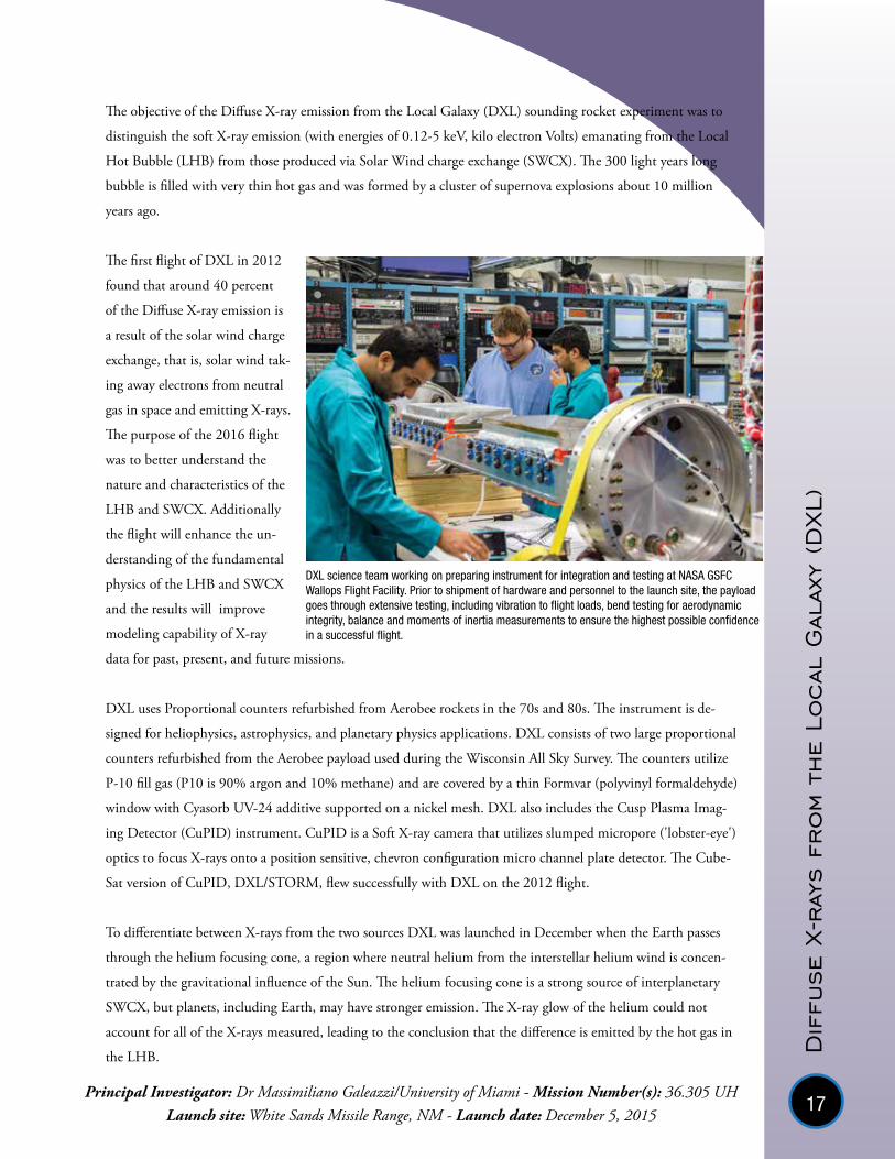
DXL science team working on preparing instrument for integration and testing at NASA GSFC Wallops Flight Facility. Prior to shipment of hardware and personnel to the launch site, the payload goes through extensive testing, including vibration to flight loads, bend testing for aerodynamic integrity, balance and moments of inertia measurements to ensure the highest possible confidence in a successful flight.

18
Good data was received during the flight and preliminary analysis confirms the finding from DXL 1 that the
X-ray contribution from the SWCX is about forty percent in the galactic plane, and even less elsewhere, and
the remaining X-rays must come from the Local Hot Bubble. DXL 2 also investigated the exact direction of the
cone, which relates directly to the motion of the Sun in the Galaxy.
DXL payload sequence testing. Sequence testing involves going through all payload inflight events, such as door openings, Attitude Control Systems operations, recovery system deployments etc. as they would happen in flight. Conducting a sequence test shows that the instrument and all payload support systems are still in working condition after all other testing is complete.

19
Colo
rado
Hig
h-r
esolu
tion
Echel
le S
tell
ar S
pectr
ogra
ph (CHESS)
Principal Investigator: Dr. Kevin France/University of Colorado - Mission Number(s): 36.297 UG Launch site: White Sands Missile Range, NM - Launch date: February 22, 2016
NASA and the University of Colorado at Boulder collaborated to launch an astrophysics experiment into Earth’s
near-space environment in order to study the life-cycle of stars in our Milky Way galaxy. The NASA/CU 36.297
UG – France mission launched off of the Athena launcher at Launch Complex 36, White Sands Missile Range,
21:15 MST, 21 Feb 2016. The CHESS-2 instrument acquired data on sightline to the hot star epsilon Persei
for the entire 400 seconds of available observing time with detector high-voltage on. The payload was success-
fully recovered the following morning at ~8am; all science-critical subsystems are alive and well, and are being
refurbished for the next flight of the CHESS payload. Comprehensive success was achieved for 36.297 UG.
CHESS was designed to study the interstellar medium (ISM), the matter between stars, and specifically translu-
cent clouds of gas which provide fundamental building blocks for star and planet formation. These clouds have
very low densities and the only way to study them is to measure absorption spectra of light from stars passing
through the cloud. CHESS was pointed at the star Epsilon Persei, in the constellation Perseus. When radiation
from this star travels through the cloud some wavelenghts of energy are absorbed by the cloud. The absorbed
wavelengths indicate the presence of specific elements, all of which have their unique spectral signatures. This
allows scientists to take a snapshot of the raw materials available, such as carbon, nitrogen, and oxygen, that
are needed to build future generations of stars and planets. The CHESS spectrograph enables the University of
Colorado team to also quantify the temperature and motions of the clouds along the line of sight.
Energy created through nuclear reactions is radi-ated by the star. .
Some wavelengths of energy are absorbed by gas that the light travels through.
The spectrograph separates radiation into wavelengths.
Scientists analyze the spectra and deduce which elements are present in the gas cloud due to the lack of energy at wavelengths corresponding to specific elements.
Absorption spectra are created when radiation from an object travels through a gas, such as a nebula, or in the case of CHESS, a translucent cloud in the ISM. The gas absorbs some of the wavelenghts of energy leading to dark bands in the spectrum. For example, molecular hydrogen (H2) has a system of absorption lines near 1100 Å, a wavelength where the Hubble Space Telescope does not have high-resolution spectroscopic capability. H2 traces cool molecular material (100 K), and makes up 99.99% of the total molecular gas in the Galaxy. If H2 is present in the cloud that the starlight passes through, the spectrograph will show less energy at wavelengths near 1100 Å. The CHESS spectrograph measures energies in the Ultraviolet part of the spectrum, 1000 - 1600 Angstrom. This covers wavelengths of, for example, Oxygen VI, H2, several levels of ionized Carbon, Fe II and Mg II (once ionized Iron and Magnesium). These elements are all important for star and planet formation.
This spectrum extracted from raw CHESS flight data shows interstellar absorption features. It shows warm (Si III) and cool (N I) interstellar features against the stellar continuum.

20
Almost all of the target absorption lines were detected by the CHESS instru-
ment, ranging from cool molecular gas (H2, T ~ 100 K) to Si IV (three times
ionized silicon, T ~ 60,000 K). Figure 1 shows an echellogram; about 120 spec-
tral orders across the 8196 pixel x 8196 pixel detector were recorded, and each
spectral order is a horizontal stripe. There is a lot of data (about 5 million science
counts in the flight were recorded). The two-dimensional spectrum shows several
neutral and ionized species (labeled). A high-level science extraction has taken
place (Figure 2), science and technical results were presented at the SPIE meeting
in June 2016 and a subsequent publication led by the project’s lead graduate
student (Keri Hoadley) is in preparation.
The refurbished high-count rate cross-strip MCP (developed, in part, as a Strategic Astrophysics Technology
program at the University of California at Berkeley, - J. Vallerga SAT program) worked beautifully in-flight,
a new echelle grating provided almost 10x the collecting efficiency as CHESS-1 (Figure 3), and this mission
served as the second flight of the new high data rate suborbital telemetry system. The PI and science team
are very happy with the performance of the CHESS system and will continue improvements as part of their
research and development program on dispersive optics, projecting another factor of ~2 increase in throughput
while decreasing instrumental scatter for the next flight, CHESS-3, June 2017.
Figure 1- 36.297 CHESS flight data, full two-dimensional echellogram with relevant molecular and atomic absorption features labeled.
Figure 3 - Component-level research and development (diffraction grating, at left) carried out as part of the CU rocket program provided ~10x the instrumental sensitivity (at right, 36.297, pink x’s) compared to CHESS-1 (36.285, blue x’s).
Figure 2 - 36.297 CHESS flight data, one-dimensional extraction.

21
The lead graduate student, Keri Hoadley, led all phases of the build-up, calibration, and integration of the
CHESS payload. She was at the command system for real-time control of the rocket during flight, “driving” the
payload to center the target stars in the aperture. The CHESS project scientist, Dr. Brian Fleming, directed a
significant portion of the field activities, gaining the PI-training that is one of the goals of the Colorado rocket
program. The University of Colorado field team also included 3 other graduate students (Nick Kruczek, Nick
Erickson, Nicholas Nell) and one undergraduate student (Jack Swanson).
CHESS and the follow on mission under development, Suborbital Imaging Spectrograph for Transition region
Irradiance from Nearby Exoplanet host stars (SISTINE), also are pathfinders and technology demonstrators for
an ultraviolet spectrograph for the NASA cosmic origins mission, Large UV/Optical/IR Surveyor (LUVOIR),
currently under study. The Combined High-resolution and Imaging Spectrograph for the LUVOIR Surveyor
(CHISL) would address topics ranging from characterizing the composition and structure of planet-forming
disks to the feedback of matter between galaxies and the intergalactic medium.
Link: http://cos.colorado.edu/~kevinf/
36.297 Recovery. Left to right: Nick Kruczek (Colorado grad student), Keri Hoadley (Colorado grad student), Brian Fleming (Colorado, CHESS project scientist)

22
Geospace Missions 2016
Rocket Experiment for Neutral Upwelling (RENU 2)
RENU studied the relationship between the inflow of electrons that creates the cusp aurora, electric currents flowing along magnetic field lines, and dense columns of heated neutral atoms in the upper atmosphere. The neutral upwelling was discovered when satellites travelling through the magnetic cusp experienced increased drag. When solar wind electrons collide with atmospheric electrons, they transfer some of their energy, heating the atmospheric electrons. The higher heat means the electron populations expand upward along the magnetic field lines.
Cusp Alfven and Plasma Electrodynamics Rocket (CAPER)
CAPER was designed to investigate electromagnetic (EM) waves that can accelerate electrons down into Earth’s atmosphere or up out to space. The electrons that are accelerated downward collide with particles in the atmosphere, releasing light and creating the cusp aurora.
Geospace science focuses on the study of interactions between Earth and the space environment surrounding our planet. Part of the broader research discipline, Heliophysics, geospace scientists study Sun-Earth connections such as effects of the solar wind on the Earth’s magnetosphere and ionosphere.
Sounding rockets are uniquely suited for many geospace research applications due to their ability to take measurements in a region of space too high for balloons and too low for satellites.
The aurora borealis, or northern lights, created when charged particles from the Sun are carried to Earth with the solar wind, are frequently studied with sounding rockets. When these solar particles reach Earth, they get trapped in the magnetic field lines created by Earth’s magnetic core. At the geomagnetic poles, the field lines extend through the lower atmosphere, allowing the charged particles to interact with atoms of mostly Oxygen and Nitrogen. The charged particles, mostly electrons, energize the atoms by exciting their electrons, causing them to move to a higher energy level. This higher energy level is not stable and when the electron transits back to its initial level it emits a photon, causing the auroral light show. High energy electrons cause oxygen to emit green light, while low energy electrons cause a red light. Nitrogen generally gives off a violet-blue light.
The higher level is unstable and when the electron transits back it releasesenergy by emitting a photon
Electrons in the gas atom or molecule (mostly oxygen and nitrogen) are energized and move to a higher level around the nucleus
Incoming energetic particles (mostly electrons) collide with atmospheric gases.
Red
620-
700
nm
Ora
nge
597-
620
nm
Yello
w57
7-59
7 nm
Gre
en49
2-57
7 nm
Blue
455-
492
nm
Viol
et40
0-45
5 nm
Red Aurora emitted by oxygen at 630 nm.
Green Aurora emitted by oxygen at 577.7 nm.
Violet-Blue Aurora emitted by nitrogen at 427.8 nm.
Light Emission

23
Complex interactions govern the Sun-Earth space environment. Coronal Mass Ejections (CME), solar flares, solar wind, and regular solar radiation influence the behavior of Earth’s atmosphere. The atmosphere is divided into several layers; starting with the troposphere closest to the Earth, the stratosphere where the ozone layer is, followed by the mesosphere and thermosphere. Of particular interest, since the beginning of the space age and the use of orbiting satellites, has been the ionosphere, a layer of partially charged or ionized gas extending in altitude from about 90 km to over 500 km. The thermosphere and ionosphere
almost overlap spatially, but the ionosphere can vary temporally, i.e., with time.
The lower ionosphere/thermosphere (90-130 km) represents a critical transition region between the neutral and ionized gas populations; this is where the two gases
couple and exchange energy. This is also the region where much external energy is deposited, from above and below, producing heating and instabilities. The thermosphere/ionosphere is coupled energetically, dynamically, and chemically to the mesosphere below and the exosphere above. Atmospheric tides, gravity waves, and planetary waves propagate upward from the mesosphere. Pressure gradients resulting from temperature differences, with the absorption of solar EUV being the dominant source of heating, influence the region from above.
The ionosphere is created by the ionization of the neutral atoms and molecules of the atmosphere. This electrical charging is the result of the Sun’s ultraviolet light bombarding the atmospheric gas, which is mainly oxygen and nitrogen molecules. The ultraviolet light knocks electrons off the gas molecules, leading to electrically charged particles or ions. Neutral molecules exist alongside the ions. Gases in the troposphere, where life
on Earth exists, are neutral, meaning that they are not electrically charged. In a neutral gas, the number of electrons surrounding the nuclei is the same
as the total number of protons in the nuclei. It is difficult to conduct large scale studies of this region, yet characterizing the ionosphere/thermosphere is
important for understanding our planet and the space surrounding it.
Changes in the ionosphere caused by variations in solar activity has an impact on everyday life on Earth and in near-space. Solar storms can disrupt the ionosphere and
cause communication black-outs. Availability and accuracy of GPS signals are impacted by changes in the ionosphere as are signals from other Earth orbiting satellites. Long conductors,
such as power grids and overhead power lines, experience additional currents due to geomagnetic storms that create electric currents in the magnetosphere and ionosphere.
The Sun’s energy is carried toward the Earth in the solar wind, a stream of electrically charged particles (mostly protons and electrons) flowing out from the Sun. The Earth’s magnetic field deflects most of these particles. Most of the highly visible aurorae occur where the magnetic field guides the electrons from the tail of the magnetosphere into the atmosphere where they produce the aurora. A different type of aurora, the cusp aurora, is produced when energetic particles are accelerated downward into the atmosphere directly from the solar wind.
The graphic shows Earth’s atmosphere and types of solar radiation and the altitudes at which the various energies are blocked. On the right is a depiction of the Ionosphere and chemical composition of molecular oxygen, nitrogen, and atomic oxygen.

24
Rocke
t Exp
erim
ent
for N
eutr
al U
pwel
ling
(RENU 2
)
Principal Investigator: Dr. Marc Lessard/Univeristy of New Hampshire• Mission Number(s): 52.002 UELaunch site: Andoya Space Center, Norway • Launch date: December 13, 2015
Rocket Experiment for Neutral Upwelling 2, studied the relationship between the flowing electrons that create
the cusp aurora and dense columns of neutral atoms in the upper atmosphere.
The cusp regions are the two funnel-shaped features
near the Earth’s magnetic poles where Earth’s magnetic
field lines connect with those of the sun. The cusp
aurora, is produced when energetic particles are ac-
celerated downward into the atmosphere directly from
the solar wind. The density of neutral atoms, meaning
they are not charged, in the atmosphere can change
throughout the day because of heating by sunlight.
The original understanding was that the increased
density of neutral particles was driven horizontally.
But satellites orbiting through Earth's magnetic cusp
experienced increased drag, which indicates a small vertical slice of
higher-density neutral atoms that are harder to travel through.
When solar wind electrons collide with atmospheric electrons, they
transfer some of their energy, heating the atmospheric electrons. The
higher heat means the electron populations expand upward along the
magnetic field lines. This upward flow of negatively-charged particles
creates a vertical electric field, which in turn, pulls up the positively-
charged and neutral particles, increasing the atmospheric density in
columns rather than horizontal layers.
RENU 2 was successfully launched on December 13, 2015 and
transited the cusp region while taking measurements. Data from this
flight is currently being analyzed.
Graphic showing upwelling in the cusp region.
RENU 2 during integration activities at NASA GSFC Wallops Flight Facility.

25
Cusp
Alf
ven
and
Pla
sma
Ele
ctr
ody
namic
s Rocke
t (C
APER)
Principal Investigator: Dr. Jim Labelle/Darthmouth College • Mission Number(s): 49.003UELaunch site: Andoya Space Center, Norway • Launch date: November 30, 2015
Cusp Alfven and Plasma Electrodynamics Rocket (CAPER) was designed to investigate the interactions be-
tween electrical waves and charged particles in a region of space known as the "polar cusp." The polar cusps are
structures in the Earth's magnetic field above the north and south poles, where the magnetic field lines converge
in a funnel-shape. The cusps are significant because they are connected directly to the solar wind, a stream of
charged particles coming out of the sun and striking the Earth's environment, giving rise to space weather ef-
fects such as loading of the radiation belts, intense auroral activity known as substorms, and strong natural elec-
trical currents lasting several days known as geomagnetic storms. These processes can have a significant impact
on ground- and space-based technical systems. By probing the cusp regions, CAPER was designed to measure
particle and wave phenomena related to these processes.
The Earth's magnetic poles are offset from its spin axis, so that the polar cusps occur at significantly higher
geographic latitudes in Europe than in North America. Furthermore, the pressure of the solar wind against
the Earth's magnetic field distorts the field, shifting the polar cusps toward the dayside. Therefore, the optical
auroral signatures of the cusp, which need to be observed in order to know when to launch CAPER, occur near
noon local time. CAPER had to be launched from Norway, because only in the European sector is the cusp
located far enough north so that it lies in darkness at noon, with cusp aurora visible, during a couple of months
of the year around Winter solstice (December/January). Over North America, the cusp occurs at lower geo-
graphic latitudes and is always daylit, implying that it is impossible to observe cusp aurora from the ground at
any time of year, and hence impossible to determine when to launch CAPER.
CAPER in the Magnetic Calibration Facility at NASA GSFC Wallops Flight Facility.

26
CAPER carried multiple instruments, providing: measurements of electric and magnetic fields of low-frequen-
cy waves, measurements of electric fields of high frequency waves, and measurements of charged particles of a
wide range of energies. Most importantly, CAPER included a unique instrument called a wave-particle correla-
tor, which combines the data of the other instruments in order to measure exactly how the charged particles
behave in the electric fields of the waves. This correlator, never before flown in the cusp region, was designed to
reveal the detailed physics whereby the charged particles are accelerated upward or downward by the waves. The
electrons, which are accelerated downward, collide with particles in the atmosphere, releasing light and creating
the cusp aurora; charged particles accelerated upward may escape Earth's gravity entirely and be lost to outer
space. CAPER was designed to reveal how these acceleration processes, which are highly significant but not
fully understood, work in detail.
Due to an anomaly in the sequence of events during the flight, the payload did not reach its intended apogee,
and no data were recorded. A re-flight "CAPER-2" is being proposed.
CAPER ready to launch from Andoya Space Center, Norway.

27Eric Taylor and Walt Suplick working on CAPER at Wallops Flight Facility.


RockOn!Level 1
RockSat-X
Level 2
Level 3
RockSat-C
RockSat-C and RockOn! experiments share payload space, but RockSat-C experiments are designed and built by students at their home institutions and brought to Wallops for integration with the payload. Students participate in payload integra-tion and testing activities and view the launch of their payload on Wallops Island.
The most advanced of the student flight opportu-nities, RockSat-X offers sounding rocket payload support systems, such as de-spin, attitude control, and deployable skins to expose the experiments to the space environment. Students are responsible for completing the design and construction of their experiment and attend integration, testing and launch activities at Wallops.
RockOn! is the first level student sounding rocket experiment. Teams of students and faculty experi-ence first hand the full scope of a sounding rocket mission, all accomplished during a one week work-shop. Participants build, test, and integrate sensors and program a datalogger, which are flown on a sounding rocket before the end of the workshop.
Education Missions 2016
RockOn! RockSat-C RockSat-X

30
RockO
n! &
RockS
at-C
Principal Investigator: Mr. Chris Koehler/Colorado Space Grant Consortium• Mission Number(s): 41.116 UOLaunch site: Wallops Island, VA • Launch date: June 24, 2016
The RockOn! workshop was held at NASA Wallops Flight Facility, June 18 - 24, 2016. Seventy-three students
and faculty members participated in this year's workshop, which was the ninth since the inception of the
program in 2008. RockSat-C experiments are flown in the same payload as the workshop experiments but are
more advance and completely designed and fabricated by the students. Ninty-three students participated in the
RockSat-C flight opportunity.
The goal of the RockOn! mission is to teach university faculty and students the basics of rocket payload
construction and integration. RockOn! also acts as the first step in the RockSat series of flight opportunities,
and workshop participants are encouraged to return the following year to design, build, test, and fly their own
experiment. The RockOn! experiments are designed to capture and record 3-axis accelerations, humidity, pres-
sure, temperature, and radiation counts over the course of the mission. All items and instruction necessary to
complete the experiment are provided for the participants during the workshop week, and teams of students
and faculty work together to build their experiment. The workshop culminates with the launch of the experi-
ments on a Terrier-Improved Orion sounding rocket.
The chart above shows the workflow for the RockOn! and RockSat-C programs.
1. RockOn! workshop participants build their experiment during the workshop.
2. All materials and instructions are provided to complete the experiment.
3. Experiment boards are stacked on an internal structure that accommodates five boards.
4. Experiment stacks are housed in canisters (RockOn!). RockSat-C experiments are not board based but are also
housed in canisters.

31
5. All canisters are integrated with the payload structure.
6. Payload is tested prior to flight. Tests include Moments of Inertia measurement (roll moment measurement
shown in picture), vibration, and balancing.
7. Payload is launched with a two-stage Terrier-Improved Orion sounding rocket before the end of the work-
shop week. Participants view the launch from Wallops Island.
RockSat-C offers students an opportunity to fly more complex experiments of their own design and construc-
tion. The intent is to provide hands-on experiences to students and faculty advisors to better equip them for
supporting the future technical workforce needs of the United States and/or helping those students and faculty
advisors become principal investigators on future NASA science missions. Teaming between educational
institutions and industry or other interests is encouraged.
The following schools and experiments flew on RockSat-C in 2016:
Community Colleges of Colorado
The experiment aimed at launching an inter-school payload to: test viability of carbon fiber shielding, gather
successful Cherenkov radiation data, and test durability of DNA under ascent and reentry conditions.
Eastern Shore Community College (Virginia)
The Eastern Shore Community College aims to expose local students (middle school and up) to aerospace
career possibilities by involving them in a STEM based project that records and saves data from a 3-axis acceler-
ometer on the RockSat-C 2016 Flight.
Hobart and William Smith Colleges (New York)
The purpose of this experiment was to determine the flux of muons at various levels within the atmosphere us-
ing a plastic scintillator detector with a solid state silicon photomultiplier
RockOn! workshop participants.

32
Old Dominion University (Virginia)
The mission of Monarch-Two was to evaluate and design a smartphone based flight system and transmitter with
flight data collection capabilities
Oregon State University
This mission aimed to measure the polarization of gamma radiation coming form outside our solar system
Stevens Institute of Technology (New Jersey)
The objective of this experiment was to test the effects of high gs and microgravity on 3D prints and to measure
High-Speed Boundary Layer Transitions from laminar to turbulent pressure waves using a piezoresistive and
pizoelectric pressure sensor combination mounted in a custom window on the skin of the rocket.
Temple University (Pennsylvania)
The goal of this experiment was to determine the concentration of sulfate based aerosols in the troposphere and
stratosphere using a series of filters and valves that were designed to open/close during the descent of the flight,
and to determine the volumetric flow rate and pressure differential between the dynamic and static port of the
rocket.
University of Delaware
The experiment was designed to study ionizing radiation during the rocket flight. The main goal this year was to
establish a permanent RockSat team at the University of Delaware.
West Virginia University
The West Virginia University team aimed to capture near infrared Earth images from space, measure plasma
density in upper atmosphere, measure atmospheric pressure and magnetic field of Earth, gather redundant flight
dynamics data, determine attitude in space relative to the sun, and test the strain of
ABS plastic in space
Cubes in Space is a program for middle school students that allows them the
opportunity to design an experiment that fits in a 1" x 1"x 1" cube. The cubes are
flown inside the nose cone of the RockOn! payload. Seventy-five middle school
payloads with approximately 375 student participants were flown on the RockOn!
mission.
Cubes in Space experiments.

33RockSat-C students and NSROC staff with the 41.116 payload on the vibration table.

34Principal Investigator: Mr. Chris Koehler/Colorado Space Grant Consortium • Mission Number(s): 46.014 UO
Launch site: Wallops Island, VA • Launch date: August 17, 2016
RockSat-X was successfully launched from Wallops Island, VA on August 17, 2016. RockSat-X carried student
developed experiments and is the third, and most advanced, student flight opportunity. The other two student
flight missions are RockOn!, an introductory workshop for building and flying experiments, and RockSat-C,
which allows students to design their own experiment, but does not offer exposure to the space environment.
RockSat-X had an ejectable skin and nose cone that fully exposed the experiments to the space environment
above the atmosphere. Power and telemetry were provided to each experiment deck. Additionally, this payload
included an Attitude Control System (ACS) for alignment of the payload. These amenities allow experimenters
to spend more time on experiment design and less on power and data storage systems.
The following experiments were flown on RockSat-X in 2016:
University of Hawaii Community Colleges
Four community colleges in Hawaii teamed up to encourage students
to explore STEM-based careers. The first primary experiment was to
measure thermal neutron and gamma background radiation using
scintillators and photomultiplier tubes. The second primary experi-
ment deployed a naphthalene sublimation mini-rocket made from
3D printed materials and capture imagery of the sublimation rocket’s
release. The secondary experiments onboard were designed to evaluate
a 9-axis IMU motion tracking device and wirelessly transfer video
from the sublimation rocket-mounted cameras back to the experiment.
University of Nebraska Lincoln
This experiment aimed to develop and streamline the mechanism
for a deployable boom and solar panel system. The deployable boom
system could be used for suborbital and small satellite missions. For
the 2016 flight, this experiment flew as a mechanical experiment only,
in order to test the resilience of the retracted boom system.
Capitol Technology University (Maryland)
This experiment, TRAPSat, used a silica aerogel to capture micro-
debris. CTU utilized this RockSat-X mission as a proof of concept
both for the use of aerogel as a medium to remove debris, as well as
to prove the viability of using aerogel blanketing as an alternative
to Multi-Layer Insulation. A camera imaged the micro-debris and
recorded data about their impact.
RockS
at-X

35
Northwest Nazarene University (Idaho)
This experiment tested flexible electronics in the space environment. Utiliz-
ing passive flexible radio frequency identification (RFID) tags, provided
by American Semiconductor, temperature was recorded, transmitted, and
received during the space flight. A boom extended an RFID tag away from
the experiment, during which temperature and transmit power was recorded
via the RFID reader powered by a smartphone. Additionally, the experiment
used a microcontroller to control and sample the American Semiconductor
FleX-Analog to Digital Converter (ADC) accelerometer alongside a tradi-
tional ADC to compare the use of flexible electronics in space.
Virginia Tech
This experiment demonstrated the capability of software defined radio
(SDR) in spaceflight communication systems. Additionally, it tested the
possibility of using economically priced SDR devices such as the Ettus
E310. Data was transmitted to the Virginia Tech Ground Station using
the Ettus E310 and a helical transmit antenna that deployed from the
rocket and pointed in the direction of the Virginia Tech Ground Station.
The transmitted packages contained gyroscope, acceleration, pressure, and
temperature data.
Carthage College (Wisconsin)
The objective of this experiment was to observe very low frequency
electromagnetic waves that come from lightning discharges. As the pay-
load increased in altitude, the experiment observed the impact that the
ionosphere has on these low frequency waves. This experiment utilized
two electric field plate antenna pairs and three magnetic loop antennas
(x,y,z-axis) to detect electromagnetic waves. The signals from the anten-
nas were amplified and then stored onboard in an xCORE computer with
microSD card.
University of Colorado Boulder
The RockSat-X High Definition video payload was intended to provide a
view of the experiments from space. The system housed four HD cameras
that recorded the flight and any deployments or activations on student
experiments. Each camera was housed in a sealed container with a pres-
sure and temperature sensor to give important data on the integrity of the
system during the flight to space.

36
University of Puerto Rico
The experiment allowed the detection of high density particles
found between 130-165 kilometers above sea level using the UPR
early micrometeorite impact detection system, collector, and vari-
ous other measuring devices. This project could aid in developing a
clearer image of space particles, and potentially lead to the discov-
ery and subsequent genome sequencing of organic materials found
within the particles. The experiment utilized a Leica SL UHD 4K
video camera pointed aft to record video of the flight. The Leica SL
was selected as an ongoing research collaboration with Bifröst Corporation to test optical behavior and camera
functionality during flight. These experiments provided data to evaluate camera performance for future missions
to visualize the aurora borealis.
This flight included the first clam shell skins. The skins were successfully deployed during flight. For more infor-
mation on the clam shell skin, see the Technology Development section of this report.
The payload was not recovered. Telemetered data was received as designed, but on-board recorded data was not.

37John Yackanech, Nic Marks, and Ahmed Ghalib (left to right) working on RockSat-X.

38

39
Technology and Special Projects Missions 2016
Sounding rockets have served as technology test beds since the beginning of the space age. New technologies and support system upgrades for the Sounding Rockets program, such as Telemetry, Attitude Control, and Recovery, to mention a few, are tested on both dedicated technology missions or as add-ons to scheduled flights. New science
instruments are tested on sounding rockets to evaluate their feasibility and functionality before committing to a longer
duration spacecraft mission.
In 2016, three dedicated technology development missions were flown and included testing of deployable sub-payloads, a standard
instrument carrier development mission, and a flight in support of NASA's Space Technology Mission Directorate (STMD) Flight Oppor-
tunities Program (FOP). All three missions were successfully flown from Wallops Island, VA. In addition, the new clam shell skin was tested
on the RockSat-X student mission.

40
Techno
logy
- Te
st a
nd S
upp
ort
Principal Investigator: Ms. Catherine Hesh/NASA GSFC Wallops Flight Facility • Mission Number(s): 36.310 GTLaunch site: Wallops Island, VA • Launch date: October 7, 2015
This NASA technology test mission’s primary goal was to fully test
and characterize the new Black Brant Mk4 motor in a sounding
rocket vehicle configuration. This was be the first flight test of the
next Mk4 version of the Black Brant rocket motor.
Additionally, the mission provided NASA and NSROC an opportu-
nity to test new technology experiments, as well as, further develop
rocket propelled sub-payload ejection technology for the Sounding
Rockets Program.
The NSROC technologies on this mission included: HD Camera
System, Quasonix transmitter SOQPSK encoding, Kulite pressure
transducers, Ampule Control Module (ACM) with rocket propelled
sub-payload ejection, and Vehicle diagnostics package.
Two new technologies, the Advanced Near Net Shape Technol-
ogy (ANNST) experiment and a materials testing experiment with
Orbital ATK, sponsored by the NASA Game Changing Office, were
also onboard. The objective of the ANNST project was to develop
and mature manufacturing technology to enable fabrication of
single-piece, integrally-stiffened launch vehicle structures to replace
expensive, heavy, and risky multi-piece welded assemblies. The novel
integrally stiffened cylinder (ISC) process improves manufacturing
efficiency and structural performance by producing single-piece stiff-
ened barrels in one manufacturing process through combined spin-
and flow-forming operations. Such a technique has never before been
applied to launch vehicle structures. A 25” flow formed aluminum
skin replaced the standard NSROC Ogive Recovery System Assem-
bly (ORSA) adapter and was flown on this mission.
The NASA and Orbital ATK experiment consisted of advanced
materials in three different designs and configurations for evaluation
of radiation and thermal heat shields, ultra-lightweight structure
design, and carbon based conductive wire.
36.310 GT launches from Wallops Island, VA.
Payload sequence testing. Open sub-payload doors are visible on the left.
NASA/Orbital ATK materials experiment mounted on deck.

41
The Autonomous Flight Safety System (AFSS), which also flew on this mission, is a joint effort by NASA’s
Wallops Flight Facility (WFF) and Kennedy Space Center (KSC) to develop an autonomous, onboard sys-
tem that can augment or replace the function of the traditional ground commanded system. The AFSS is an
independent, self-contained subsystem mounted onboard a launch vehicle. The system autonomously makes
flight termination/destruct decisions using configurable software-based rules implemented on redundant flight
processors using data from redundant GPS/IMU navigation sensors. The Low Cost Transmitter (LCT) 2 is a
WFF project to enable a launch vehicle to communicate via satellite rather than line of sight TM. Although
AFSS can act autonomously, it is anticipated that data to evaluate its actions will be required. LCT2 provides
bi-directional communication through NASA's Tracking and Data Relay Satellite System (TDRSS) that meets
suborbital and orbital launch vehicle needs for Space Based Range (SBR) communications.

42
Mult
iple
Use
r S
uborbital
Ins
trumen
t Car
rie
r (M
USIC
)NASA has long recognized the utility of sounding rockets with
respect to workforce training and development. Sounding rocket
mission and instrument development provide hands-on experi-
ence for technicians, engineers, and managers. Design, fabrica-
tion, and testing phases of a sounding rocket mission, while
technically rigorous, are relatively fast compared with other
spaceflight opportunities, with a mission completion time, from
design to launch, of about 18-months.
MUSIC provided NASA Applied Engineering and Technology Directorate (AETD) personnel an opportunity
to gain experience in developing sounding rocket technology, conduct systems engineering processes, and test
NASA AETD experiments. This mission resulted in a standard payload carrier with predefined mechanical,
te lemetry, power, and attitude control capabilities to be offered to reimbursable customers and other Wallops
Flight Facility organizations.
The payload carried experiments/instruments developed by AETD including, Wheel Tracker Experiment
(WTE), Diminutive Assembly for Nanosatellite deploYables (DANY), GoPro camera, solid state altimeter,
Temperature and Strain measurement, Strain Gauge management System (SGMS), and Iridium GPS Beacon.
Some of these experiments have been improved and are considered for upcoming Sounding Rocket flights.
Additional experiments from West Virginia University’s Undergraduate Student Instru ment Program (USIP)
include instruments for Plasma Physics and Flight Dynamics with GPS and camera.
Launch occurred on Tuesday, March 1, 2016. The vehicle flew to an Apogee of 185.5 km with all payload sys-
tems performing nominally. The payload was recovered.
Principal Investigator: Mr. Carsell Milliner/NASA GSFC Wallops Flight Facility • Mission Number(s): 46.011 GPLaunch site: Wallops Island, VA • Launch date: March 1, 2016
West Virginia University students integrating their experiment.
MUSIC team with payload during integration at Wallops Flight Facility.

43
Spe
cial
Proje
cts
Principal Investigator: Mr. Paul De Leon/NASA Ames Research Center • Mission Number(s): 41.114 NPLaunch site: Wallops Island, VA • Launch date: March 7, 2016
Three new technologies sponsored by NASA's Space Technology Mis-
sion Directorate (STMD) Flight Oppor tunities Program (FOP) were
supported by this mission. The technologies included Montana State
University’s RadPC, Controlled Dynamics Vibration Isolation Platform
(VIP), and NASA Ames Sub-Orbital Aerodynamic Re-Entry Experi-
ments (SOAREX-9). Sounding rockets enable rapid devel opment and
testing of new technologies, thereby increasing the Technical Readiness
Level (TRL) of instruments intended for future space flight missions.
The RadPC is a computer system that uses a novel architecture designed
and built using off-the-shelf parts. This technology provides increased
reliability in the presence of high-energy radiation at a fraction of the
cost of existing rad-hard computer systems, where spare circuits are
brought online to replace other circuits that may have been struck
by ionizing radiation. During this test, the engineers were looking to
increase the TRL by demonstrating it in increasingly challenging space
environments. The system has been tested on commercial high-altitude
balloons, NASA scientific balloons, and commercial subor bital rockets.
The VIP, a vibration isolation platform, is used to reduce spacecraft disturbances during microgravity. VIP has
also flown on developmental flights on both the space shuttle mission STS-73 and two commercial suborbital
rockets. VIP provides a free-floating mounting platform that is completely isolated from the disturbances and
vibrations of the host vehicle or other payloads. Non-contact isolation allows the experiment to float freely in
the sway space between the host vehicle and the platform. Active stabilization allows the platform to cancel any
disturbance from the experiment or connected umbilicals, and allows for precisely controlled acceleration envi-
ronments uniquely tailored to the mounted payload. For optical payloads, this includes scanning and precision
tracking. For g-sensitive research experiments, this includes programmable excitations designed to influence and
optimize the research results.
The SOAREX-9 experiment tested several technologies for the first time,
and matured other components that have evolved from a previous test
flight conducted from Wal lops in July 2015. Wireless Sensor Modules
(WSM) are now much smaller and more capable. Also, the camera tech-
nology was improved. This was an incremental test flight, and the results
are being applied to the TechEdSat 6 and TechEdSat 7 nano-sat missions
which are planned to be launched from the ISS in 2017. SOAREX-9 also
enabled development of techniques needed to get optical and WSM data
through the downlink directly to the satellite telemetry receivers at Wallops during a TechEdSat-5 over flight.
Link: http://www.nasa.gov/directorates/spacetech/flightopportunities/index.html
PI Mr. De Leon with the vehicle on the launcher.
RadPC team.
SOAREX-9 team.

44

45
STEM Education
Educating the next generation of engineers and scientists starts with opportunities to engage in exciting projects. The Sounding Rockets Program Office (SRPO) and NASA Sounding Rocket Operations Contract (NSROC) offer opportunities for teachers and students to participate in rocketry related activities.
The Wallops Rocketry Academy for Teachers and Students (WRATS) workshop is offered annually to High School teachers
interested in incorporating rocketry activities in their teaching.
NSROC and SRPO staff visit schools to give lectures, arrange rocketry activities and judge science fairs. Additionally, tours are
given to groups of all ages of the payload manufacturing and testing areas.
NSROC manages the internship program and recruits about 10 - 15 interns annually from Universities and Colleges. The interns work with
technicians and engineers on rocket missions and gain invaluable work experience.

46
Wal
lops
Rocke
try
Acad
emy
for T
eacher
s an
d Stu
dent
sThe Wallops Rocketry Academy for Teachers and Students (WRATS)
workshop is hosted by the Sounding Rockets Program Office and
NSROC with support from the Wallops Education Office. 2016 was
the 5th year of the workshop with 20 teachers selected from over 80
applicants. Teachers came from as far away as New York state and as
near as Accomack County, VA. All participating educators teach STEM
topics at the High School Level.
WRATS offers a unique, in-depth learning experience where teachers
not only get hands-on practice building rockets, but are exposed to
rocket physics through interactive lectures conducted by Office Chief,
Phil Eberspeaker. Topics such as aerodynamics, propulsion, recovery
system design, and trajectory simulations are covered in detailed presen-
tations and then put into practice with rocket and payload construction
activities.
WRATS starts with overviews of the Sounding Rockets Program and
model rocketry, followed by construction of an E-powered model
rocket. Tours of sounding rocket Testing and Evaluation facilities and a
visit with the RockOn! workshop students are also included. By the end
of the first day, all teachers have a flyable model rocket.
On the second day, teachers build an electronic payload to measure
acceleration, temperature. and pressure during flight. The payload is
based on the Arduino microprocessor and inexpensive sensors. Recov-
ery system design and construction are also completed.
Once all the construction activities are completed, the models are
launched and recovered at Wallops Flight Facility. Flight data is then
plotted and analyzed.
The week ended with the launch of the RockOn! mission from Wallops
Island.

47
Inte
rns
hip
s an
d Outr
each
Internships
Over 190 students have participated in the internship program managed for the
Sounding Rockets Program Office by NSROC. The program, now in its 17th
year, provides internships and co-op opportunities for students studying engineer-
ing, computer science, electrical or mechanical technology, as well as business
disciplines. Students work side-by-side with experienced engineers and managers
to perform significant, valuable tasks, leading to a better understanding of the
work in a highly technical environment. Almost 90 percent of undergraduate
students who intern or participate in the co-op program return for additional em-
ployment. Several participants in the program have gone on to pursue
higher education in the engineering and science fields.
In 2016, NSROC provided opportunities for nine internships involv-
ing all engineering disciplines.
Outreach
Throughout the year, SRPO and NSROC personnel support local schools by providing speakers, judging sci-
ence fairs, and conducting special programs, such as model rocket launches. Additionally, speakers are provided
upon request to local civic organizations through the NASA Office of Communications.

48
49
Technology Development
The SRPO and NSROC are actively engaged in upgrading and developing new technologies for the program. This year has seen several new and major initiatives to enhance program capabilities including firings of a prototype rocket motor and spin motors, a new launcher, and several payload systems upgrades.
Continuous development efforts allow new and emerging technologies to be incorporated into payload systems fairly
quickly. Thorough testing ensures that these technologies are ready for operational use. In-house technology flights are often
used to validate new technologies without exposing science missions to any risks that this may involve. Also, several new
technologies can share a flight, reducing cost for any one system.
50
The NASA Sounding Rocket Program (NSRP) continues to assess new technologies in order to expand the ca-
pabilities for our science and technology customers, address obsolescence, and to improve efficiency. The major
initiatives of the NSRP technology roadmap continue to focus on (1) providing increased scientific observation
time for Solar and Astrophysics missions, (2) increasing the telemetry data rates from the current capability of
10 to 20 Mbps to systems with rates ranging from 40 to ~400 Mbps, and (3) developing free-flying sub-payload
technologies. The NSRP leverages resources from NSROC, the NASA Applied Engineering and Technology
Directorate, the WFF Technology Investment Board, Small Business Innovative Research (SBIR), and Internal
Research and Development (IRAD) programs to meet our growing technology needs.
In pursuit of the initiative to increase scientific observation time, the NSRP assesses opportunities to utilize
alternate surplus and commercial solid rocket motor assets, assesses alternate launch vehicle configurations
utilizing the current stable of assets, and assesses alternate concepts for mission operations. One approach is
to conduct missions at water-based launch ranges to address the vehicle performance limitations driven by
land-based ranges. The Solar and Astrophysics sounding rocket missions are typically flown from the land-based
White Sands Missile Range (WSMR). While this facilitates recovery, the relatively narrow range boundaries of
WSMR limit the type of vehicle that can be launched from WSMR, consequently limiting the science observa-
tion time. Conducting such a mission from a water-based range would allow for higher performing launch ve-
hicles and increased science data periods. However, water-based ranges come with the increase risk to recovery.
In an attempt to mitigate that risk, NSROC has focused on test and evaluation of the existing vacuum shutter
door and modified shutter doors. 2016 brought promising test results for the enhanced shutter door design
and has led to a planned flight test on the 36.317 Hesh (SubTEC-VII) mission in the coming months. Based
on analysis, ground testing, and the upcoming flight demonstration, NSRP hopes to offer this capability for
water recoverable missions launching on BBIX and larger vehicles. The NSRP continues investing in flotation
technologies, over-the-horizon location aides, and alternate recovery capabilities to facilitate the move to BBX
and larger vehicles.
In the avionics area, the Program continues to ensure we maintain the standard systems and assess new avionics
systems that can provide increased telemetry data rates, improved power density, and new avionics capabilities.
The major goal of the new capabilities assessment is to increase the telemetry system data rates and to provide
high data rate on-board storage. The program continues to utilize 10 and 20Mbps S-band telemetry systems
to transmit data from the sounding rocket payload to the ground stations. There are ongoing efforts to signifi-
cantly increase data rates, potentially up to 400 Mbps, by assessing commercially available hardware as well as
purpose-built custom hardware. A portion of the currently utilized systems can be tuned to alternate bands,
such as C-band, and products are available that provide dual channel (S and C-bands) or C-band capability. The
Program will continue to pursue flight systems capable of providing higher data rates and alternate frequency
band compatibility while we pursue the authorization to utilize alternate frequency bands and work with launch
ranges to assess ground support system upgrades.

51
In recent years, the science community has pushed for enhance capabilities for deployable, free-flying sub-pay-
loads capable of carrying chemical tracers or science instruments. Numerous hardware and software develop-
ments have been made to develop and enhance support systems for these ampules, including ejection systems
and control logic to activate deployment and detonation (chemical tracers) to ensure science and safety criteria
are met. In 2016, much focus has been on improving the ignition system for the rocket propelled ampules and
enhancing the ignition system for the chemical tracer ampules. Recent activities include analysis, ground-based
testing of ignition train components, ground-based testing of ignition systems, and planning for an upcoming
flight test. A summary of some of the major 2016 technology activities follows.
Water Recovery Shutter Door
NSROC developed a modified vacuum shutter door assembly for water recovery payloads, with a goal of en-
abling water recovery for telescope payloads on BBIX class vehicles. The system leverages the heritage vacuum
shutter door design and incorporates a water-wedge feature similar to the crushable bumper design commonly
utilized for telescope payloads. NSROC conducted a series of drop tests to evaluate the performance of the
heritage shutter door assembly and the new design under conditions anticipated for a water impact. The new
design performed well and has been chosen to be flown on an upcoming test flight to be launched from WFF.
The water recovery shutter door system is anticipated to become operational upon successful completion of the
test flight.
Clamshell Skin Development
NSROC continued development of a load bearing clamshell
skin design which is intended as a replacement for both long
skirts and large deployable doors. By replacing a convention-
al skirt, the clamshell skin removes the chance of the skin
touching the structure as it deploys. When used to replace
a large blow-off door, the clamshell provides the structural
support of a skin, while allowing the same working volume
as a blow-off door system. NSROC completed the initial Clam shell skin deployment testing.
Water recovery testing,
Engineering drawings of shutter door with water wedge and payload.

52
round of prototype testing in 2015 and continued into 2016 with additional
structural testing and functional testing. The clamshell skin system was success-
fully tested on the 46.014 Koehler (RockSAT-X) mission in August of 2016.
Free-Flying Ampule Development
The NSRP, through NSROC, AETD, industry, and the science communi-
ty, has continued the development of the rocket-propelled ampule system.
This design initially conceived by the science community for chemical
tracer distribution also has utility for spatial distribution of small instru-
ment packages. The NSROC team worked with vendors and industry
experts to improve the reliability of ignition for the small, commercially
available solid motors used to deploy the ampules. The team conducted
analysis, design modifications, and ground tests in an attempt to improve
the reliability for upcoming science missions.
High Data Rate Encoder
NSROC continues to work closely with Ulyssix to develop the 50 Mbps Phoenix PCM En-
coder. In 2016, the team continued to develop and test prototype decks for this next genera-
tion encoder.
Embedded Engineering:
The NSRP has brought in dedicated engineer staff to support research and development initiatives. This staff
will focus on early concept technologies for the program and work closely with other teams and programs to
seek out areas for collaboration and development of cross-cutting technologies. Highlights of some of these
developments are as follows.
Microcontroller Altimeter: Designed as a solid state architecture replacement to the
legacy plenum chamber. The new design will increase reliability and precision as well as
lower manufacturing costs.
Solid State Lanyard: Designed as a “drop-in” replacement for the legacy mechanical
lanyard switch, the solid state design seeks to improve reliability, precision, manufacturability,
and cost. The new design provides the same functionality as the legacy design but increases the
channel capacity.
Autonomous Rocket Tracker (A.R.T.): Designed to facilitate recovery of expended solid
rocket motor stages for clean-up of land-based launch range areas, this Iridium/GPS bea-
con is designed to mount on the exterior of a solid rocket motor, function autonomously,
and survive the harsh flight and re-entry environment. This capability will aide the NSRP
and launch ranges in locating and removing expended motor stages.
Engineering drawing of Clam shell skin.
Ampules being prepared for integration at Wallops.

53
Upcoming Technology Development Flights
36.317 Hesh (Sub-TEC 7) – Winter 16/17 from Wallops Island, VA.
Objectives for this mission include providing NASA and NSROC an opportunity to test new technology
experiments and demonstrate water recoverable vacuum shutter door. Additionally NASA's Space Technology
Mission Directorate (STMD) is sponsoring experiments flying on this mission.
Planned Experiments include
Reimbursable – Sponsored by NASA STMD/Game Changing Development Office:
NASA Glenn Carbon Nanotube Composite Overwrap Pressure Vessel (CNT COPV)
Orbital ATK LEO-2 CubeSat experiment with 3D printing and nanotechnology
NASA Langley Mars Rover Packing Efficiency Experiment (self-contained)
Reimbursable – Commercial Experiments
Tyvak nano avionics experiment (NASA SBIR)
Science Flight Opportunity
RIT CSTARS Cryogenic Star Tracker (36.281 Bock)
NASA AETD Experiments:
Low cost star tracker
Autonomous rocket tracker
Microcontroller Altimeter
Solid state lanyard
NSROC Experiments:
Water Recovery Shutter Door (22”)
NSROC Forward OGIVE Recovery Section (N-FORSe)
40-50 Mbps Ulyssix PCM stack
Solar sensors
Current sensor
Vacuum monitor
Power supply
Timer
Uplink stack and receiver
Transmitter
Vibrometers
Processor in a frame
Analog to Serial Board
Inertial Measurement Unit (IMU)

54
Peregrine Static Firing
Two static firings of the prototype Peregrine sustainer motor were
conducted on Wallops Island. The firings were conducted in a
purpose-built horizontal safety restraint cage. The motors were
instrumented with pressure, thermal, strain, and vibration sensors. In
addition, photographic, video, high speed video, and thermal imag-
ing products were recorded to support evaluation of performance.
Even though the firings resulted in anomalous insulation perfor-
mance, they provided valuable design evaluation information. Data
collected will be used in a NESC sponsored re-design effort.
Prototype Spin Motor
The first test firing of the prototype spin motor was successfully con-
ducted. The goal of the effort is to upgrade the existing spin motor
design to a safer, less restrictive propellant hazard classification. The
new classification will reduce safety concerns in addition to minimiz-
ing logistical, shipping, and storage issues. Six prototype cartridge
grains have been cast with the first successful static test being con-
ducted in September 2016. The first firing was conducted in a newly
designed all aluminum motor case and was very successful, verifying
all new design elements of the prototype motor.
Peregrine static firing on Wallops Island, VA.
Thermal camera overlay of Peregrine plume.Aerial view of test firing operation on Wallops Island, VA.
Prototype aluminum spin motor case.
Spin motor firing.Spin motor grains.

55
Medium Mobile Launcher (MML)
The Medium Mobile Launcher (MML)
is the first launcher to be developed
in-house by NSROC. The project
began in 2014, and has progressed
through design, fabrication, and test-
ing and is nearly ready to be declared
operational. The MML was designed
to fill a void between the capacity of
the mobile Missouri Research Labora-
tory (MRL) launcher and that of the
semi-permanent Astro Met Laboratories
(AML) 20K launcher, both already in
use by SRPO. The MML is designed to
launch vehicles as large as a Black Brant
X (Terrier-Black Brant-Nihka) with a
1,000 pound payload. The launcher can
also accommodate an extension on the
forward end for umbilical rigging and
for a retractable “zero-length” rail mechanism. The entire system will be stored and shipped in two standard
shipping containers: one 40’ long and one 20’ long. The first intended use of the MML is the 2019 sounding
rocket campaign in Australia.
The development of the new launcher was executed by a team of NSROC personnel from various groups. These
include Launcher Systems, Mechanical, Electrical, Flight Performance, and Launch vehicle Engineering, as well
as the Machine Shop, the Electrical Fabrication Shop, Safety & Mission Assurance, and Mission Management.
Side-Opening Vacuum Doors
Mission 36.305 Galeazzi featured a particularly exciting engineering
and fabrication challenge for NSROC. The science instrument had
five detectors that were very large and required a field of view that
could only be achieved by orienting them to look out the side of the
payload. Furthermore, the cleanliness requirements for the three of
the five detectors necessitated a vacuum-sealed enclosure while in the
Earth’s atmosphere. The mission team responded by developing five
large, side-opening doors, three of which were vacuum-sealed.
MML launcher on Wallops Island.
SolidWorks model of the MML.
SolidWorks model of the Side-Opening Vacuum Door.

56
The complex nature of the doors each required multiple moving parts and
fine adjustments during assembly for proper opening, closing, sealing, and
locking. Furthermore, environmental testing of the fully built payload
required additional effort due to the doors. For example, mass properties
measurements were conducted with doors closed, and again with doors
open. Also, because of the extreme length of the payload, spin balance was
conducted in two separate operations.
The doors performed nominally during launch, maintaining the required
vacuum level on the three vacuum-sealed doors. All five operated properly
by fully opening and closing on either side of science data collection. The
two non-vacuum-sealed doors experienced anomalies on re-entry, however,
resulting in damage to two science detectors. In the end, the Principal
Investigator received good science data.
Manufacturing Cells
NSROC has implemented an approach in the Machine Shop
where one machinist operates multiple machines. This has
proved effective at increasing operator efficiency. One example
of this approach may feature a lathe making an individual skin
section and a milling machine doing high volume runs of small
parts, with a single machinist setting up and operating both.
This work cell implementation has resulted in an increase in
overall production capacity in the Machine Shop, reducing
back-log. This has also reduced the need for outsourcing, while
maintaining the NSROC mission schedule. Furthermore, an
overall cost reduction per part has been achieved from the im-
proved efficiencies.Machining cells - one machinist operating several machines.
36.305 UH Galeazzi payload with side-opening vacuum doors prior to launch at White Sands.

57Nate Wroblewski with the water wedge.

58

59
On the Horizon
New opportunities to conduct science missions in the Southern Hemisphere are being developed by SRPO. Two launch sites in Australia are being evaluated for use in 2019 for Astrophysics missions.
FY 2018 will see several flights from launch sites in Norway. The campaign involves both US, Norwegian, and
Japanese scientists and an international student mission. Two US science flights will launch from Svalbard and two
from And�ya. The Norwegian and Japanese rockets will launch from And�ya. All missions study the polar ionosphere
and Cusp region.
Additionally, SRPO is returning to the Kwajalein Atoll in 2017 to launch two rockets to study the stability of the post sunset
equatorial F region ionosphere.

60
Kwajalein 2017
The SRPO will once again be returning to the Regan Test Site (RTS) in the Kwajalein Atoll to conduct equato-
rial science investigations. For many years, the SRPO has been trying to provide more routine opportunities for
our scientists to study the equatorial ionosphere, with this investigation we are one step closer. Dr. David Hysell
of Cornell University was selected to conduct the Waves and Instabilities from a Neutral Dynamo (WINDY)
from Kwajalein in late August-early September 2017.
WINDY will study the stability of the post sunset equatorial F region ionosphere and the factors that predis-
pose it to equatorial spread F (ESF), a spectacular phenomenon characterized by broadband plasma turbulence,
which degrades radio and radar signals at low magnetic latitudes. The goal of the investigation is to lay the
foundation for a strategy to forecast this disruptive phenomenon. The Advanced Research Projects Agency
(ARPA) Long-Range Tracking and Instrumentation Radar (ALTAIR) will be used in conjunction with other
ground based instruments to monitor the state of the upper atmosphere/ionosphere and help determine if the
scientific conditions are suitable for launch.
SRPO and NSROC crews are busy making launch site preparation with a service trip planned for the first of
the year. SRPO is once again working with the RTS staff to make a few more permanent site improvements that
should help reduce costs on future missions.
Grand Challenge (GC) - Norway FY 2018
Four science investigations and one student mission will be launched as part of the Grand Challenge (GC) –
Cusp Initiative in northern Norway. The GC is a joint international science campaign being managed by the
AndØya Space Center with help and assistance from NASA’s SRPO. The first GC Initiative is designed to bring
together an array of scientist from the radar community, scientific modeling community, and sounding rocket
researchers to focus their efforts on the Cusp. At present, the NASA component includes two science investi-
gations with four launch vehicles. Two launches will take place from AndØya Space Center and the other two
from the SvalRak launch range in Ny-Ålesund, Svalbard. The Principal Investigators are Dr. Craig Kletzing,
University of Iowa, and Dr. Douglas Rowland, Goddard Space Flight Center. The University of Oslo and the
Japanese space agency JAXA will also be launching one investigation, both from SvalRak as part of the GC.
To help inspire and train the next generation of engineers and scientists, a joint US-Norway student mission,
RockSat-XN, is planned to be launched in the second phase of the GC planned for January 2019. The student
mission is similar to the Colorado Space Grant Consortium RockSat-X concept and is designed to bring stu-
dents from Norway and the US together in a joint international mission.
The NASA science missions, VISualizing Ion Outflow via Neutral atom imaging during a Substorm 2 (VI-
SIONS-2) with Principal Investigator Dr. Rowland and Twin Rockets to Investigate Cusp Electrodynamics 2
(TRICE-2) with Principal Investigator Dr. Kletzing, will both study the polar ionosphere and Cusp region.

61
VISIONS-2 is specifically designed to investigate the outflow
of oxygen ions from Earth's upper atmosphere and into the
magnetosphere. This mission will observe the phenomenon
during the day from Earth's magnetic cusps— regions near
Earth's poles where the magnetic field lines dip down toward
the ground. This information will lead to a better understand-
ing of the physics that influence the Earth's magnetosphere,
the region where most space assets, including communications
satellites, reside. Such satellites are sensitive to severe space
weather caused by the solar wind.
Magnetic reconnection has emerged as a major topic of inter-
est for both space-based and laboratory plasma physics. The
process occurs in a variety of plasmas from controlled fu-
sion devices to our near-Earth plasma environment, as well
as for astrophysical plasmas, such as solar flares and stellar
atmospheres. The TRICE-2 scientific goals are aimed at
distinguishing between signatures of pulsed reconnection
versus those of steady reconnection, as well as investigating
ionospheric cusp electrodynamics. By examining the evolution
of stepped cusp ion dispersion along nearly identical field lines
at a variety of different times, the team can determine if the
stepped forms have moved due to convection as predicted by
pulsed reconnection models, or if the steps are fixed in latitude
as predicted by steady reconnection models. The comprehen-
sive suite of measurements will allow a detailed study of the
temporal physics of current closure, incident Poynting flux,
Alfven wave occurrence, and high frequency waves.
While this is the first GC initiative, there is hope it will lead to future collaboration on topics of scientific
interest from a variety of scientific disciplines. Future missions and researchers may be added as the campaign
matures. However planning is now underway for the core of the GC missions.
Two BB X’s launched to >700 km in the cusp. Measurements are taken in conjunction with EISCAT, SuperDARN, ASIs, and ground-based magnetometers.
A sample TRICE trajectory. The thin lines indicate the geodetic positioning of the payload and the thick lines indicate the magnetic foot-point track of the two payloads. The grey lines indicate the lines of magnetic latitude. NOTE: These trajectories have not been optimized for science conditions.

62
Australia Campaign
With a long tradition of launching sounding rockets from Australia, SRPO is once again planning to return
to the "Land Down Under." While there is a long history of Sounding Rockets in Australia dating back to the
60s, it has been a while since we have launched from there. Three highly successful campaigns were conducted
in 1987, 1988, and 1995 from the Woomera Test Range (WTR). The launches in 1987 studied the Supernova
1987A (a supernova in the outskirts of the Tarantula Nebula in the Large Magellanic Cloud), and were followed
by another three launches in 1988 studying the same supernova. Additionally, six missions were launched in
1995 to study the Large Magellanic Cloud (LMC) in the ultraviolet and x-ray wavelengths. The LMC is only
visible from the Southern Hemisphere.
SRPO is now considering two options for conducting launch operations in a Southern Hemisphere campaign:
a return to WTR, or engaging a new launch range Equatorial Launch
Australia (ELA). Both sites offer unique opportunities with unique chal-
lenges.
The WTR is located in South Australia and is a “trials area” for testing
of defense systems. Sufficient space, facilities, and infrastructure exists
to meet most of our requirements, with Wallops mobile range capabili-
ties being utilized for telemetry, power conversion, and wind weighting.
Black Brant IX class vehicles can be accommodated without waivers or
range extensions.
ELA is a new range under development for both sub-orbital and
orbital launches from the Northern Territory. Presently, minimal
infrastructure exists. However, the site has great potential due to its
unique location. Extensive mobile operations support is required
to enable launches from ELA, but this is not unusual for the
SRPO with the remote campaigns we have conducted in the past.
The large, uninhabited landing areas allow vehicles up to a Black
Brant XI to be launched and recovered. This extends the capabili-
ties for telescope missions by providing more observation time. Apogees on the order of 400 km (320 for BBIX)
lead to approximately 20% more observation time above 150km.
ELA
Planned launch area at ELA.Meeting area at the Garma Knowledge Center.

63NASA team during the 2004 Kwajalein campaign.

64
Charts
0510152025
0607
0809
1011
1213
1415
16
Number of Launches
Fisc
al Y
ear
Sou
ndin
g R
ocke
t Lau
nche
sFY
200
6 -2
016
Tota
l num
ber o
f lau
nche
s: 1
84
Laun
ches
Vehi
cle
Suc
cess
Mis
sion
Suc
cess
Mis
sion
Succes
s His
tory

65
Sound
ing R
ocke
t Ve
hic
les

66
Sound
ing R
ocke
t Ve
hic
le P
erfo
rman
ce

67
Poker Flat, Alaska
Andøya, Norway Woomera, Australia
Kwajalein, Marshall Is.
Wallops Island, Virginia
Esrange, Sweden
Sounding Rocket Launch Sites
Past and present world wide launch sites used by the Sounding Rockets Program to conduct scientific research:
8. Wallops Island, VA9. Fort Churchill, Canada *10. Greenland (Thule & Sondre Stromfjord) *11. Andøya, Norway12. Esrange, Sweden13. Svalbard, Norway14. Woomera, Australia
1. Kwajalein Atoll, Marshall Islands2. Barking Sands, HI3. Poker Flat, AK4. White Sands, NM5. Punta Lobos, Peru *6. Alcantara, Brazil *7. Camp Tortuguero, Puerto Rico *
* Inactive launch sites
2
3
4
5
6
7
8
9 10 1112
13
14
1

68
Philip J. Eberspeaker
Chief, Sounding Rockets Program Office
Ph: 757-824-2202
Email: [email protected]
Emmett D. Ransone
Asst. Chief, Sounding Rockets Program Office
Ph: 757-824-1089
Email: [email protected]
Margaret Thompson
Grants & Admin Support
Ph: 757-824-1615
Email: [email protected]
Julie Bloxom
Business Manager/Grants Manager
Ph: 757-824-1119
Email: [email protected]
Charles L. Brodell
Vehicle Systems Manager
Ph: 757-824-1827
Email: [email protected]
Brian Hall
Technical Manager
Ph: 757-824-1477
Email: [email protected]
Catherine Hesh
Technology Manager
Ph: 757-824-1408
Email: [email protected]
John C. Hickman
Operations Manager
Ph: 757-824-2374
Email: [email protected]
Gordon Marsh
Operations Manager
Ph: 757-824-1166
Email: [email protected]
Carsell Milliner
Technical Manager
Ph: 757-824-4665
Email: [email protected]
Giovanni Rosanova
Payload Systems Manager
Ph: 757-824-1916
Email: [email protected]
Todd Thornes
Safety and Mission Assurance Manager
Ph: 757-824-1557
Email: [email protected]
Elizabeth L. West
SRPO Projects Manager
Ph: 757-824-2440
Email: [email protected]
Todd Winder
Resource Analyst
Ph: 757-854-4693
Email: [email protected]
Contact Information

69
Sounding Rockets Program Office personnel
Margaret ThompsonGrants & Admin Support
Philip EberspeakerChief
Emmett RansoneAssistant Chief
Brian HallTechnical Manager
Giovanni RosanovaPayload Systems Manager
John HickmanOperations Manager
Charles BrodellVehicle Systems Manager
Carsell MillinerTechnical Manager
Elizabeth WestSRPO Projects Manager
Julie BloxomBusiness/Grants Manager
Todd WinderResource Analyst
Catherine HeshTechnology Manager
Gordon MarshProjects Manager
Todd ThornesSafety & Mission Assurance
Manager 69

Image Credits1 Launch photos:Wallops Imaging Lab10 Alignment image - NASA/MSFC/Emmett Given14 Dr. Chakrabarti15 NGC 1365 SSRO/PROMPT and NOAO/AURA/NSF16 Dr. McCandliss20 Dr. France21 White Sands Missile Range22 Aurora background image - Terry Zaperach23 Aurora insert image - Scott Hesh24 Neutral Upwelling: Dr. Marc Lessard/University of New Hampshire26 Caper on launcher - Dr. Labelle40 Launch photo - Wallops Imaging Lab43 All images - Mr. De Leon51 Engineering drawings - Shane Thompson51 Drop testing - T&E lab staff51 Clam shell deployment - T&E staff52 Clam shell Engineering drawings - Mike Tolbert52 Component images - Brian Hall53 SolidWorks drawing - Max King54 All images courtesy - Chuck Brodell55 MML launcher, Solidworks models- Phil Cathell56 Galeazzi payload - Ted Gacek61 VISIONS trajectory - Dr. Doug Rowland61 TRICE trajectory - Dr. Craig Kletzing62 ELA images - Jay Scott63 Group photo - Nowhereatoll65 Vehicle stable grahic: NSROC Mechanical Engineering66 Performance graph: NSROC Flight Performance69 John Brinton
Other images and report design by Berit Bland/BBCO - NSROC/SRPO support contractor.Science mission information submitted by Principal Investigators.

71

National Aeronautics and Space Administration
Goddard Space Flight CenterWallops Flight Facility34200 Fulton StreetWallops Island, VA 23337www.nasa.gov/centers/wallops
www.nasa.gov