Embed Size (px)
Citation preview

A Publication for Surveying and Mapping Professionals
Issue 2011-1
NASA Rocketeers
Stonehenge
Updating Gare St. Lazare
Gold Mine in the Congo
INSIDE:Welcome to the latest issue of Technology&more!
Trimble Engineering & Construction5475 Kellenburger Rd.Dayton, OH, 45424-1099Phone: 1-937-233-8921 Fax: 1-937-245-5145Email: T&[email protected]
Published by: Editor-in-Chief: Omar SoubraEditorial Team: Angie Vlasaty; Lea Ann McNabb; Heather Silvestri; Eric Harris; Susanne Preiser;Emmanuelle Tarquis; Grainne Woods; Christiane Gagel; Lin Lin Ho; Bai Lu; Echo Wei; Maribel Aguinaldo; Masako Hirayama; Stephanie Kirtland, Survey Technical Marketing TeamArt Director: Tom Pipinou
Dear Readers,
Welcome to the first issue of Technology&more for 2011. As in every issue since 2004, you’ll find a wide variety of innovative and exciting projects in which our customers are involved around the world. Each of these projects demonstrates the enhanced productivity and capability that are gained through the use of Trimble® technology.
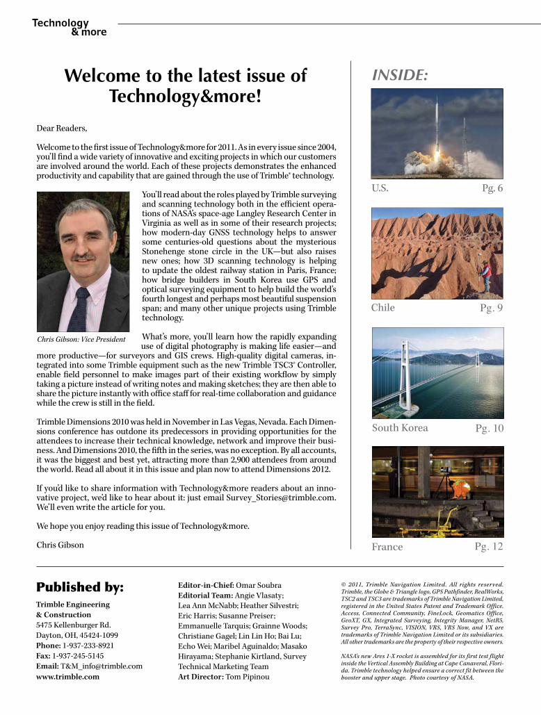
You’ll read about the roles played by Trimble surveying and scanning technology both in the efficient opera-tions of NASA’s space-age Langley Research Center in Virginia as well as in some of their research projects; how modern-day GNSS technology helps to answer some centuries-old questions about the mysterious Stonehenge stone circle in the UK—but also raises new ones; how 3D scanning technology is helping to update the oldest railway station in Paris, France; how bridge builders in South Korea use GPS and optical surveying equipment to help build the world’s fourth longest and perhaps most beautiful suspension span; and many other unique projects using Trimble technology.
What’s more, you’ll learn how the rapidly expanding use of digital photography is making life easier—and
more productive—for surveyors and GIS crews. High-quality digital cameras, in-tegrated into some Trimble equipment such as the new Trimble TSC3® Controller, enable field personnel to make images part of their existing workflow by simply taking a picture instead of writing notes and making sketches; they are then able to share the picture instantly with office staff for real-time collaboration and guidance while the crew is still in the field.
Trimble Dimensions 2010 was held in November in Las Vegas, Nevada. Each Dimen-sions conference has outdone its predecessors in providing opportunities for the attendees to increase their technical knowledge, network and improve their busi-ness. And Dimensions 2010, the fifth in the series, was no exception. By all accounts, it was the biggest and best yet, attracting more than 2,900 attendees from around the world. Read all about it in this issue and plan now to attend Dimensions 2012.
If you’d like to share information with Technology&more readers about an inno-vative project, we’d like to hear about it: just email [email protected]. We’ll even write the article for you.
We hope you enjoy reading this issue of Technology&more.
Chris Gibson
© 2011, Trimble Navigation Limited. All rights reserved. Trimble, the Globe & Triangle logo, GPS Pathfinder, RealWorks, TSC2 and TSC3 are trademarks of Trimble Navigation Limited, registered in the United States Patent and Trademark Office. Access, Connected Community, FineLock, Geomatics Office, GeoXT, GX, Integrated Surveying, Integrity Manager, NetR5, Survey Pro, TerraSync, VISION, VRS, VRS Now, and VX are trademarks of Trimble Navigation Limited or its subsidiaries. All other trademarks are the property of their respective owners.
NASA's new Ares 1-X rocket is assembled for its first test flight inside the Vertical Assembly Building at Cape Canaveral, Flori-da. Trimble technology helped ensure a correct fit between the booster and upper stage. Photo courtesy of NASA.
Chile Pg. 9
France Pg. 12
Chris Gibson: Vice President
www.northstarstudio.com
U.S. Pg. 6
South Korea Pg. 10
-1- Technology&more; 2011-1
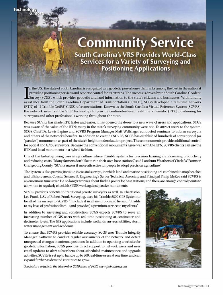
In the U.S., the state of South Carolina is recognized as a geodetic powerhouse that ranks among the best in the nation at providing positioning services and geodetic control for its citizens. The success is driven by the South Carolina Geodetic Survey (SCGS), which provides geodetic and land information to the state’s citizens and businesses. With funding
assistance from the South Carolina Department of Transportation (SCDOT), SCGS developed a real-time network (RTN) of 42 Trimble NetR5™ GNSS reference stations. Known as the South Carolina Virtual Reference System (SCVRS), the network uses Trimble VRS™ technology to provide centimeter-level, real-time kinematic (RTK) positioning for surveyors and other professionals working throughout the state.
Because SCVRS has made RTK faster and easier, it has opened the doors to a new wave of users and applications. SCGS was aware of the value of the RTN; many in the state’s surveying community were not. To attract users to the system, SCGS Chief Dr. Lewis Lapine and SCVRS Program Manager Matt Wellslager conducted seminars to inform surveyors and others of the network’s benefits. In addition to creating SCVRS, SGCS has established hundreds of conventional (or “passive”) monuments as part of the state’s height modernization project. These monuments provide additional control for optical and GNSS surveyors. Because the conventional monuments agree well with the RTN, SCVRS clients can use the RTN and local monuments in a hybrid fashion.
One of the fastest-growing uses is agriculture, where Trimble systems for precision farming are increasing productivity and reducing costs. “Many farmers don’t like to run their own base stations,” said Landrum Weathers of Circle W Farms in Orangeburg County. “SCVRS makes it more attractive for people to adopt precision agriculture.”
The system is also proving its value in coastal surveys, in which land and marine positioning are combined to map beaches and offshore areas. Coastal Science & Engineering’s Senior Technical Associate and Principal Philip McKee said SCVRS is an enormous time saver. He no longer worries about finding points for base stations, and there are enough control points to allow him to regularly check his GNSS work against passive monuments.
SCVRS provides benefits to traditional private surveyors as well. In Charleston, Lee Frank, L.S., of Robert Frank Surveying, uses his Trimble 5800 GPS System to tie all of his surveys to SCVRS. “I include it in all my proposals,” he said. “It adds to my level of professionalism…(and provides) a premium service to my clients.”
In addition to surveying and construction, SCGS expects SCVRS to serve an increasing number of GIS users with real-time positioning at centimeter and decimeter levels. The GIS applications include wetlands surveys, utilities, storm water management and academia.
To ensure that SCVRS provides reliable accuracy, SCGS uses Trimble Integrity Manager™ Software to conduct regular assessments of the network and detect unexpected changes in antenna positions. In addition to operating a website for geodetic information, SCGS provides direct support to network users and uses email updates to alert subscribers about scheduled maintenance and upgrade activities. SCVRS is set up to handle up to 200 real-time users at one time, and can expand further as demand continues to grow.
See feature article in the November 2010 issue of POB: www.pobonline.com
Community ServiceSouth Carolina’s VRS Provides World-Class
Services for a Variety of Surveying andPositioning Applications
-2- Technology&more; 2011-1
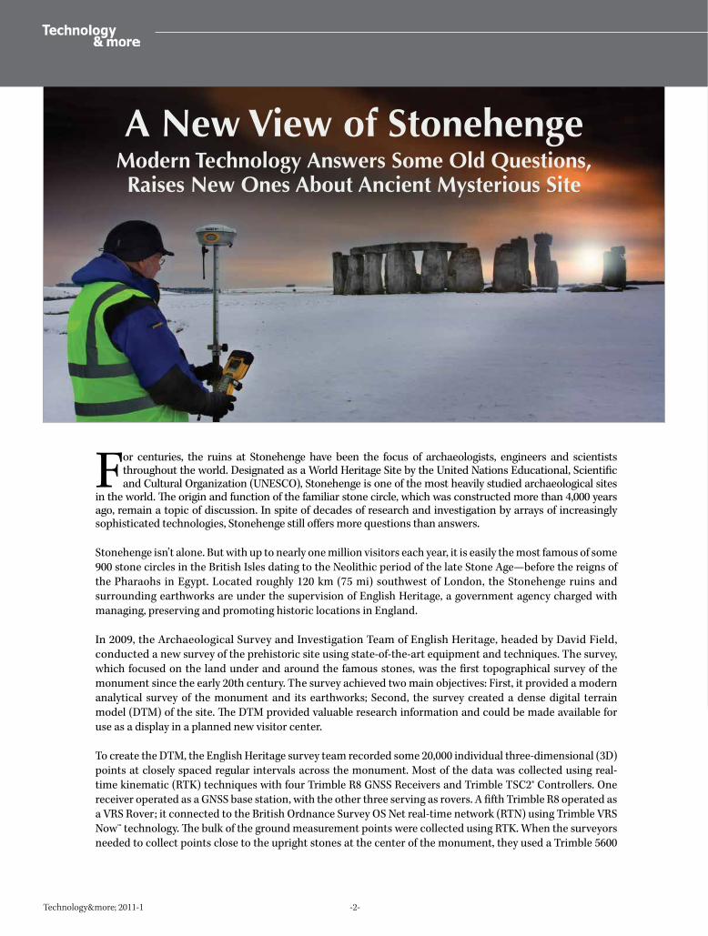
For centuries, the ruins at Stonehenge have been the focus of archaeologists, engineers and scientists throughout the world. Designated as a World Heritage Site by the United Nations Educational, Scientific and Cultural Organization (UNESCO), Stonehenge is one of the most heavily studied archaeological sites
in the world. The origin and function of the familiar stone circle, which was constructed more than 4,000 years ago, remain a topic of discussion. In spite of decades of research and investigation by arrays of increasingly sophisticated technologies, Stonehenge still offers more questions than answers.
Stonehenge isn’t alone. But with up to nearly one million visitors each year, it is easily the most famous of some 900 stone circles in the British Isles dating to the Neolithic period of the late Stone Age—before the reigns of the Pharaohs in Egypt. Located roughly 120 km (75 mi) southwest of London, the Stonehenge ruins and surrounding earthworks are under the supervision of English Heritage, a government agency charged with managing, preserving and promoting historic locations in England.
In 2009, the Archaeological Survey and Investigation Team of English Heritage, headed by David Field, conducted a new survey of the prehistoric site using state-of-the-art equipment and techniques. The survey, which focused on the land under and around the famous stones, was the first topographical survey of the monument since the early 20th century. The survey achieved two main objectives: First, it provided a modern analytical survey of the monument and its earthworks; Second, the survey created a dense digital terrain model (DTM) of the site. The DTM provided valuable research information and could be made available for use as a display in a planned new visitor center.
To create the DTM, the English Heritage survey team recorded some 20,000 individual three-dimensional (3D) points at closely spaced regular intervals across the monument. Most of the data was collected using real-time kinematic (RTK) techniques with four Trimble R8 GNSS Receivers and Trimble TSC2® Controllers. One receiver operated as a GNSS base station, with the other three serving as rovers. A fifth Trimble R8 operated as a VRS Rover; it connected to the British Ordnance Survey OS Net real-time network (RTN) using Trimble VRS Now™ technology. The bulk of the ground measurement points were collected using RTK. When the surveyors needed to collect points close to the upright stones at the center of the monument, they used a Trimble 5600
A New View of StonehengeModern Technology Answers Some Old Questions, Raises New Ones About Ancient Mysterious Site
-3- Technology&more; 2011-1
Total Station with a Trimble TSC2 Controller. Data collected with the total station could be placed into the same dataset used for the RTK surveys, and the GNSS and total station data were combined to produce a single DTM.
To successfully integrate data from GNSS and total stations, the height values recorded by GNSS needed to agree with those recorded by the total station. Even a small datum shift or difference in accuracy between the two systems would create discontinuities in the resulting DTM. Because later analyses would look for subtle variations in the DTM, any discontinuities could be mistaken for actual surface features. Rather than trying to match the GNSS and total station data in the office, the team integrated the two data sets in the field. Because the Trimble R8 and Trimble 5600 use the same controller and field software, the teams used resections to orient the total station into the same 3D reference datum as the data collected using GNSS. The approach worked well, and the resulting DTM depicted a continuous surface of 3D points recorded with GNSS and the total station.
Spatial Imaging and Integrated SurveyingTo supplement the topographic surveys, surveyors col-lected point cloud data and imagery of the stones. For this work, Matthew Lock from UK Trimble distributor KOREC supplied a Trimble Spatial Imaging Rover, which combines a Trimble VX™ Spatial Station with a Trimble Integrated Surveying™ (IS) rover. The Trimble VX Spatial Station pro-vides spatial imaging capability including scanning and image capture. The Trimble IS Rover consists of a Trimble R8 GNSS Receiver mounted directly above a 360° prism on a pole that also holds a Trimble TSC2 Controller. The Trimble TSC2 controls both instruments simultaneously, communi-cating with the Trimble VX over a radio link and with the Trimble R8 via Bluetooth. The solution enabled Lock and the surveyors to collect points on the site with RTK GNSS, the Trimble VX, or both.
The reference frame for the survey work at Stonehenge was the British Ordnance Survey coordinate system (OS Grid). To tie the Trimble VX into the OS Grid, the surveyors used Integrated Surveying to conduct a resection based on points created using RTK GNSS in conjunction with the local Trimble VRS Now service. As each resection point was cap-tured with RTK, the Trimble VX measured to the prism and developed the solution for the spatial station’s 3D position. This method enabled the team to create geometrically strong resection solutions and to develop precise, accurate ties to the OS grid. Lock noted that the method does not require setting any ground marks, which is an important consideration on the sensitive Stonehenge site.
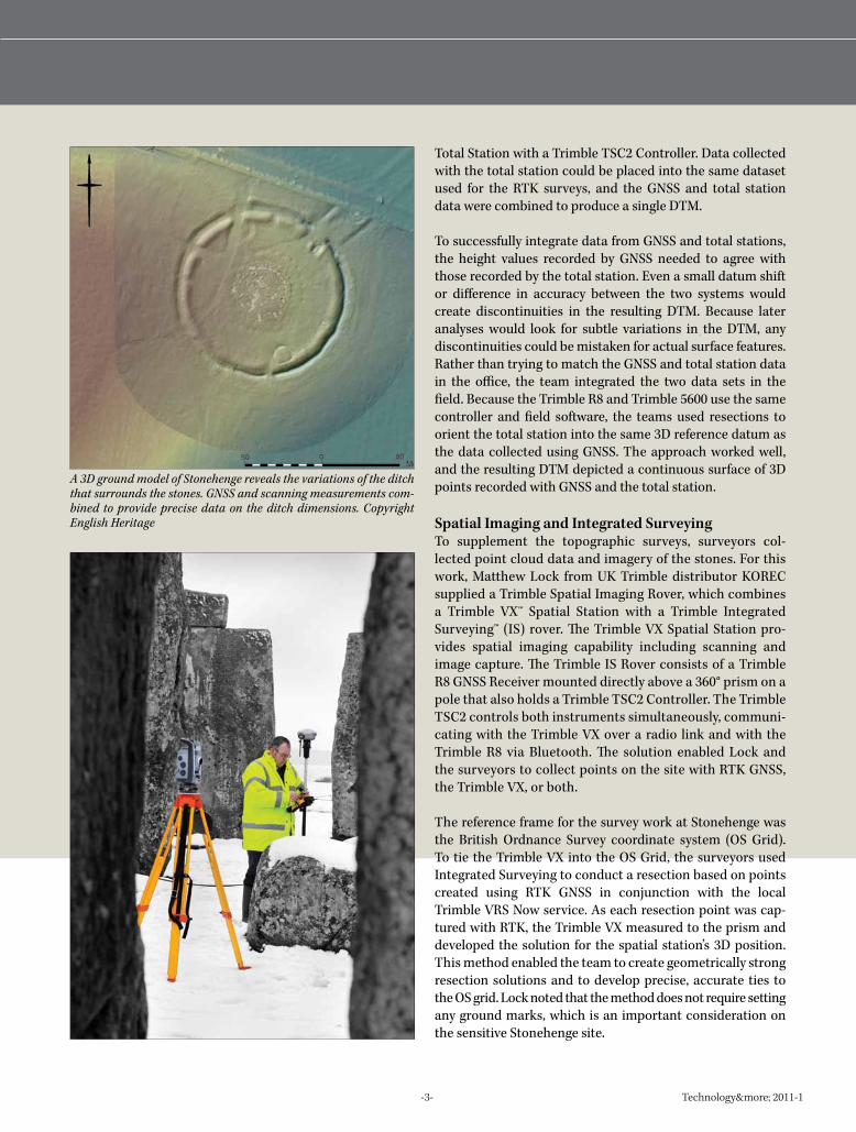
A 3D ground model of Stonehenge reveals the variations of the ditch that surrounds the stones. GNSS and scanning measurements com-bined to provide precise data on the ditch dimensions. Copyright English Heritage

-4- Technology&more; 2011-1
Steb Fisher Photography - www.steb.com.au Photo by Helena Darvelid
Once the Trimble VX was positioned, the surveyors captured photos and initiated scanning routines to capture point clouds of the stones. With the Trimble VX running autonomously, the team was free to use the Trimble R8 to survey the surrounding landscape and collect data for the DTM. The Trimble VX and Trimble R8 could operate simultaneously; data from the two sensors was recorded into the same Trimble TSC2 Controller. In the office, the 3D survey points collected by the Trimble R8 and Trimble VX were merged with the point clouds to provide a surface DTM, a 3D model of the stones and photographic data for the site.
When the survey results were analyzed, the DTM illustrated the topographic setting of the monument on the edge of an eastward-facing spur. A small ditch encircles the Stonehenge site, and the DTM showed how the form of the ditch and ditch bank changes in various locations around the monument. In some locations the ditch is deep and wide, while in others it barely exists.
Perhaps the most striking outcome of the survey work was the discovery of a slight, flattened mound near the center of the stone circle. The mound, which had not been mapped before, attracted the attention of historians and archaeologists. The purpose of the mound remains a mystery. It could be an artificial mound covering a prehistoric burial, or it might be a natural feature that was incorporated into the construction of the stone circle over four thousand years ago. Once again, Stonehenge has a new secret.
Stonehenge: Why?Why does Stonehenge exist? Why did the ancient Neolithic civilization(s) that created it invest so much time, energy and resources in its construction? And why did they choose this location?
Built and used in sporadic episodes over a period from 3100 BC to 1100 BC (very approximately), the task was obviously of continuing priority for the civilization. And the location was apparently significant, as many of the multi-ton stones were brought in from as much as 402 km (250 mi) away.
A common opinion is that it was built and used for religious purposes. This could possibly account for the massive prolonged efforts to complete it. Discovery of cremated remains of more than 250 people indicates it functioned as a cemetery.
Because of its precise alignment relative to the sun at the summer and winter solstices, some say it was intended as a calendar and astronomical observatory.
Others believe that it served as a site for celebrations or festivals, which could also be related to religious observances and/or the changing of the seasons as determined by its calendar functions.
No firm answers; just questions, which continue to make Stonehenge an object of mystery and wonder.
Copyright English Heritage Copyright English Heritage

-5- Technology&more; 2011-1
Banro Chief Surveyor Mike Trenor says Banro’s mission for the Twangiza project is continued resource expansion. “Presently only about 10 percent of the total Twangiza license has been explored,” Trenor said. “Banro hopes that continued regional exploration will add oxide and transitional resources.”
Banro has also created community partnerships to sup-port the regulated mining project while improving the area’s living standards. Through the Banro Foundation, the company has built two new schools and a potable water system serving 18,000 people, and has rehabilitated more than 50 km (31 mi) of roads and bridges in the Twangiza area. Several new projects are planned for 2011.
Surveying under rigorous conditions Situated on the edge of the Rift Valley, the Twangiza Project lies at the northern end of the Itombwe Mountains. At 1,500–3,000 m (4,900–9,800 ft) above sea level with deep valleys and few or no roads, access was initially limited to helicopter, with communication by HF radio and satellite phones. National survey reference network points were destroyed by local inhabitants at the outset of Congo’s independence in 1960. Banro had to establish a geodetic control network from scratch.
Under these rugged conditions, Banro provided real-time measurements with Trimble R8 GNSS Rovers and Trimble
TSC2 Controllers using Trimble Survey Pro™ Software. “Trimble RTK GNSS equipment is used for almost all our day-to-day survey work,” says Trenor. Today there is road access to the mine site and cell phone networks have penetrated to all project areas.
Surveying for increased productivityBanro used AUSPOS (an online GPS processing service) to fix a primary control point. They then used static GNSS observations and Trimble Geomatics Office™ Software to establish a control network. To survey the difficult and dangerous faces in the artisanal pit, control is brought in by RTK and then completed by total station. Trimble GNSS receivers also provided essential ground control data. As Banro moves into mining, more rovers will be used for mine layout and repeated volumetric surveys. Accuracy requirements are dependent on the type of survey carried out, but typically for RTK are on the order of 25 mm (1 in).
One of the important tasks undertaken by Banro surveyors is the positioning of completed exploration drilling. All exploration diamond drill collars are surveyed and fixed using Trimble technology, pro-viding repeat measurements to prove the accuracy of the results.
See feature article in American Surveyor's March issue: www.amerisurv.com
An Integrated Solution for theTwangiza Mine Project
The Twangiza-Namoya gold belt in the eastern Democratic Republic of Congo (DRC) is potentially one of the world’s most exciting undeveloped gold deposits today. Canadian-based gold exploration company Banro Corporation acquired control of the Twangiza property in 1996; Banro has since invested more than US $80
million in exploration and is currently building a gold plant and mine at a cost of US $184 million. Scheduled to begin mining operations in late 2011, Banro aims to process 1.3 million tons of ore per year.
-6- Technology&more; 2011-1
Rocketeers3D Scanning Plays a Central Role in NASA Research and Testing
The NASA Langley Research Center (LaRC) in Hampton, Virginia, is the country’s oldest civilian facility for aeronautical and aerospace research. LaRC was established in 1917 as an aeronautical research laboratory in association with a military airfield (now Langley Air Force Base). The center served as the initial home to Project
Mercury, America’s first manned spaceflight program, and has participated in testing or development of virtually every type of aircraft flown by the U.S. military.
As the Langley center evolves, it relies on accurate surveying and GIS data for planning, engineering and operations. The Center Operations Directorate’s GIS team, a small group of surveyors, engineers and GIS professionals, provides spatial information and related services to Langley’s operations and facilities managers. In addition to these services, the team uses 3D scanning to support research and development work at Langley.
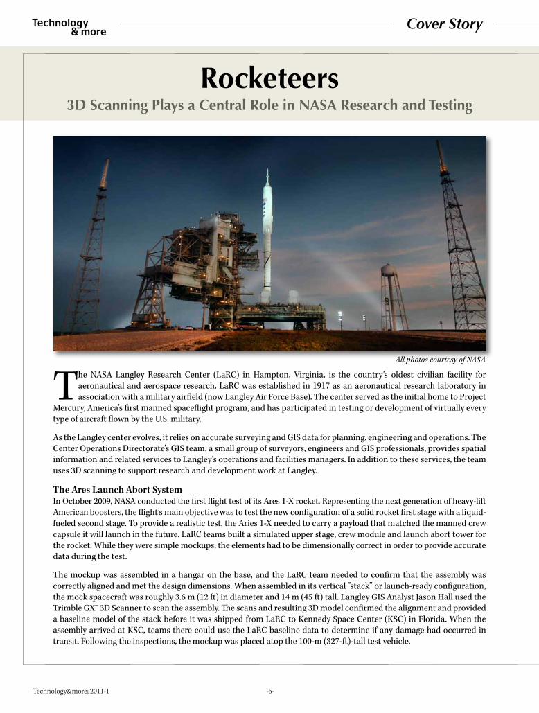
The Ares Launch Abort SystemIn October 2009, NASA conducted the first flight test of its Ares 1-X rocket. Representing the next generation of heavy-lift American boosters, the flight’s main objective was to test the new configuration of a solid rocket first stage with a liquid-fueled second stage. To provide a realistic test, the Aries 1-X needed to carry a payload that matched the manned crew capsule it will launch in the future. LaRC teams built a simulated upper stage, crew module and launch abort tower for the rocket. While they were simple mockups, the elements had to be dimensionally correct in order to provide accurate data during the test.
The mockup was assembled in a hangar on the base, and the LaRC team needed to confirm that the assembly was correctly aligned and met the design dimensions. When assembled in its vertical ”stack” or launch-ready configuration, the mock spacecraft was roughly 3.6 m (12 ft) in diameter and 14 m (45 ft) tall. Langley GIS Analyst Jason Hall used the Trimble GX™ 3D Scanner to scan the assembly. The scans and resulting 3D model confirmed the alignment and provided a baseline model of the stack before it was shipped from LaRC to Kennedy Space Center (KSC) in Florida. When the assembly arrived at KSC, teams there could use the LaRC baseline data to determine if any damage had occurred in transit. Following the inspections, the mockup was placed atop the 100-m (327-ft)-tall test vehicle.
Cover Story
All photos courtesy of NASA
-7- Technology&more; 2011-1
Everything worked well. On October 28, the module rocketed to an altitude of 46 km (150,000 ft) and traveled 240 km (150 mi) downrange before landing in the Atlantic Ocean. Plans called for the LaRC modules to not be recovered after the flight, so the pre-flight scans were crucial in preserving complete flight data.
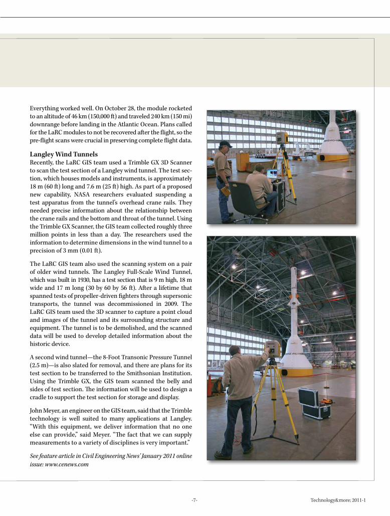
Langley Wind TunnelsRecently, the LaRC GIS team used a Trimble GX 3D Scanner to scan the test section of a Langley wind tunnel. The test sec-tion, which houses models and instruments, is approximately 18 m (60 ft) long and 7.6 m (25 ft) high. As part of a proposed new capability, NASA researchers evaluated suspending a test apparatus from the tunnel’s overhead crane rails. They needed precise information about the relationship between the crane rails and the bottom and throat of the tunnel. Using the Trimble GX Scanner, the GIS team collected roughly three million points in less than a day. The researchers used the information to determine dimensions in the wind tunnel to a precision of 3 mm (0.01 ft).
The LaRC GIS team also used the scanning system on a pair of older wind tunnels. The Langley Full-Scale Wind Tunnel, which was built in 1930, has a test section that is 9 m high, 18 m wide and 17 m long (30 by 60 by 56 ft). After a lifetime that spanned tests of propeller-driven fighters through supersonic transports, the tunnel was decommissioned in 2009. The LaRC GIS team used the 3D scanner to capture a point cloud and images of the tunnel and its surrounding structure and equipment. The tunnel is to be demolished, and the scanned data will be used to develop detailed information about the historic device.
A second wind tunnel—the 8-Foot Transonic Pressure Tunnel (2.5 m)—is also slated for removal, and there are plans for its test section to be transferred to the Smithsonian Institution. Using the Trimble GX, the GIS team scanned the belly and sides of test section. The information will be used to design a cradle to support the test section for storage and display.
John Meyer, an engineer on the GIS team, said that the Trimble technology is well suited to many applications at Langley. “With this equipment, we deliver information that no one else can provide,” said Meyer. “The fact that we can supply measurements to a variety of disciplines is very important.”
See feature article in Civil Engineering News' January 2011 online issue: www.cenews.com

-8- Technology&more; 2011-1
For more than 90 years, NASA’s Langley Research Center (LaRC) in Hampton, Virginia, has played a leading role in America’s aviation and space research. The center’s work ranges from research that
first enabled aircraft to fly at supersonic speeds to development of mod-ern methods for orbital rendezvous and docking.
Today, LaRC is home to roughly 3,800 employees working in more than 290 buildings and structures spread over 319 hectares (788 acres). The Center Operations Directorate’s GIS team provides surveying, posi-tioning and related services needed for base operations. To handle the workload, the LaRC GIS team uses a combination of Trimble technologies including real-time kinematic (RTK) GNSS, robotic total stations, spatial imaging and advanced GIS and survey data management. In addition to these services, LaRC’s GIS team manages the base’s GIS database and assists in facilities planning and management. The LaRC team also helps other NASA bases to take advantage of advanced positioning technology.
The team’s flexibility was important on a project at the LaRC Gantry (B1297). Constructed in 1963 for lunar landing simulations, the gantry is an enormous structure: 73 m (240 ft) tall, 81 m (265 ft) wide and 122 m (400 ft) long. As part of the work to install a new crane atop the gantry, the GIS team used their Trimble VX Spatial Station to measure the deflection of the gantry as loads were applied to the crane. LaRC GIS Analyst Jason Hall said that the video and automatic pointing capabilities of the Trimble VX played a major role. “It made things a lot easier,” said Hall. “With the Trimble VX video, I could control it from the data collector and didn’t have to look through the eyepiece.” The VX made things safer as well: by using the video, the crew did not need to stand under the structure.
On a separate project to validate existing aerial photos of the base, the LaRC team used the Trimble R8 GNSS Receiver to survey roughly 1,000 points visible in the photos. The work revealed the need for new, high-resolution images of the base. To provide control for the new photos, they used Integrated Surveying techniques to combine RTK with measure-ments from their Trimble S6 Total Station. All of the points became part of LaRC’s GIS database. The team also does interior surveys and carries control for the GIS into buildings and utility tunnels.
LaRC GIS Team Leader Brad Ball says that the team’s key to success is integrating surveying with GIS and in putting advanced technology into the hands of creative people. The investment pays off in letting them do things that would be difficult or nearly impossible without the new approaches.
See feature article in Professional Surveyor's November 2010 issue: www.profsurv.com
Starring RoleAt NASA’s Langley Research Center, Even the Surveyors
are Pushing the Technology Envelope

-9- Technology&more; 2011-1
For nearly 300 years, the Inca civilization was the largest society in South America. At its height, the empire extended more than 4,000 km (2,500 mi) from central Chile northward to Ecuador. The Inca roadway system—known as the Qhapaq Ñan (Great Inca Road)—was made up of more than 40,000 km (25,000 mi) of primary and secondary roads as well as countless
smaller routes.
Surveying the Qhapaq Ñan
Because of its age and cultural significance, the Qhapaq Ñan has been proposed as a World Heritage Site to the United Nations Educational, Scientific and Cultural Organization (UNESCO). In addition to preservation, the designation stimulates a site’s local economy with publicity and tourism. Meeting stringent UNESCO requirements called for detailed surveys. The Chilean firm Geometrica, located in Antofagasta, was selected to provide surveying and mapping services for portions of the Qhapaq Ñan in Chile. The project’s objective was to survey the alignments of the roadways and locate the numerous archaeological features along the road. Geometrica selected Trimble R8 GNSS Systems for the project. “The real-time kinematic surveying allowed us to use fewer workers in the field, which reduced foot traffic on the sites,” said Geometrica Senior Engineer Luis Pino Bavestrello. “Each surveyor could work as a one-person team and with knowledge of the points required in the survey. It was an excellent optimization of resources and time.”
Geometrica divided each work site into sections. Archaeologists guided the survey-ors by pointing out the existing archaeological elements along the Qhapaq Ñan. The surveyors collected position and attribute information on ancient features including the roadbed, cairns, mortars, tombs, animal pens, petroglyphs, copper concentra-tions, pottery, structures and rock alignments. The archaeologists supplemented the positioning data with detailed information to be used by the project’s GIS.
Working in the remote areas posed interesting challenges. In unpopulated regions, the crews carried food and water to last for ten days. When the surveyors were working near villages, local residents helped to provide food and lodging. On one occasion, locals fired their guns in an attempt to drive the surveyors away from the land. The team’s architect was slightly wounded, and police intervened to enable the surveyors to complete their work.
In roughly four months, the Geometrica teams surveyed more than 25 km (15 mi) of roadways and created maps of 16 archaeological sites with a combined area of ap-proximately 132 hectares (326 acres). All of the points were tied to the national grid within the project’s required accuracy. With the first phase of the project complete, Geometrica is looking ahead to extending the maps and database for the Qhapaq Ñan. “Thanks to the productivity of the Trimble GNSS equipment, we completed our work quickly,” said Geometrica Land Survey Engineer Cesar Morales Duran. “Compared to our experience on previous jobs, we reduced the survey time by more than 50 percent.”
See feature article in Professional Surveyor's September 2010 issue: www.profsurv.com
The Great Inca Road in South America is One of the Largest Roadway Systems Ever Built. A Chilean Company is Helping to Preserve it as a World Heritage Site.

-10- Technology&more; 2011-1
t’s going to be a beautiful bridge.
Near the southern tip of the Republic of Korea (South Korea), the new Yi Sun-sin Bridge will soon connect the city of Gwangyang with its neighbor to the south, Yeosu. Named for a famous 16th-century Korean admiral, the new bridge will open a direct route between the two cities’ commercial areas, eliminating the need for cars and trucks to follow a circuitous 60-km (37-mi) route. The bridge will cut travel time between the cities from more than one hour down to ten minutes. With a total length of 2.26 km (1.4 mi), the bridge’s central span is the fourth-longest in the world. Planned for completion in autumn 2011, the US $400-million project will be a key attraction for YEOSU Expo 2012, which is expected to draw thousands of visitors to the Yeosu-Gwangyang metropolis.
The bridge’s design is a three-span suspension, with two main pylons roughly 1.5 km (0.93 mi) apart. The pylons, which stand roughly 270 m (890 ft) tall, are the tallest concrete pylons ever built. When seen in cross section, the pylons have a trapezoidal shape, which provides both aesthetic and aerodynamic advantages. The pylons curve gently inward and taper towards the top. It’s a complex geometry that produces graceful, visually pleasing results.
The bridge’s three-span design offers excellent structural integrity and good visibility for vessels sailing beneath it. The four-lane roadway will be 20.7 m (67.9 ft) wide and will utilize twin box girder construction for strength and wind resistance. The suspension design provides a floating roadway, which offers improved traffic capacity as well as resistance to damage by earthquakes.
DAELIM Industrial Company began construction on the bridge in 2009 with the placement of foundations for the two massive pylons. The pylons were erected using slipform technology, in which concrete is poured continuously as the form moves slowly up the pylon. As the slipforms move up the tapering pylon, they are adjusted to produce the correct shape. The slipform approach is faster than stationary forms, and there are no construction joints in the finished structure.
Vertical Curves
Long Distances and Complex Shapes Stand Tall on a Bridge Project in Korea
I
-11- Technology&more; 2011-1
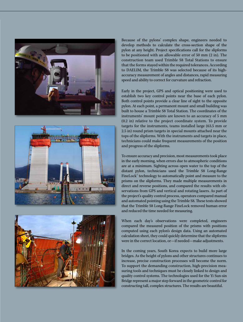
Because of the pylons’ complex shape, engineers needed to develop methods to calculate the cross-section shape of the pylon at any height. Project specifications call for the slipforms to be positioned with an allowable error of 50 mm (2 in). The construction team used Trimble S8 Total Stations to ensure that the forms stayed within the required tolerances. According to DAELIM, the Trimble S8 was selected because of its high-accuracy measurement of angles and distances, rapid measuring speed and ability to correct for curvature and refraction.
Early in the project, GPS and optical positioning were used to establish two key control points near the base of each pylon. Both control points provide a clear line of sight to the opposite pylon. At each point, a permanent mount and small building was built to house a Trimble S8 Total Station. The coordinates of the instruments’ mount points are known to an accuracy of 5 mm (0.2 in) relative to the project coordinate system. To provide targets for the instruments, teams installed large (63.5 mm or 2.5 in) round prism targets in special mounts attached near the tops of the slipforms. With the instruments and targets in place, technicians could make frequent measurements of the position and progress of the slipforms.
To ensure accuracy and precision, most measurements took place in the early morning, when errors due to atmospheric conditions are at a minimum. Sighting across open water to the top of the distant pylon, technicians used the Trimble S8 Long-Range FineLock™ technology to automatically point and measure to the prisms on the slipforms. They made multiple measurements in direct and reverse positions, and compared the results with ob-servations from GPS and vertical and rotating lasers. As part of the project’s quality control process, operators compared manual and automated pointing using the Trimble S8. These tests showed that the Trimble S8 Long-Range FineLock removed human error and reduced the time needed for measuring.
When each day’s observations were completed, engineers compared the measured position of the prisms with positions computed using each pylon’s design data. Using an automated calculation sheet, they could quickly determine that the slipforms were in the correct location, or—if needed—make adjustments.
In the coming years, South Korea expects to build more large bridges. As the height of pylons and other structures continues to increase, precise construction processes will become the norm. To support the demanding construction, high-precision mea-suring tools and techniques must be closely linked to design and quality control systems. The technologies used for the Yi Sun-sin Bridge represent a major step forward in the geometric control for constructing tall, complex structures. The results are beautiful.
-12- Technology&more; 2011-1
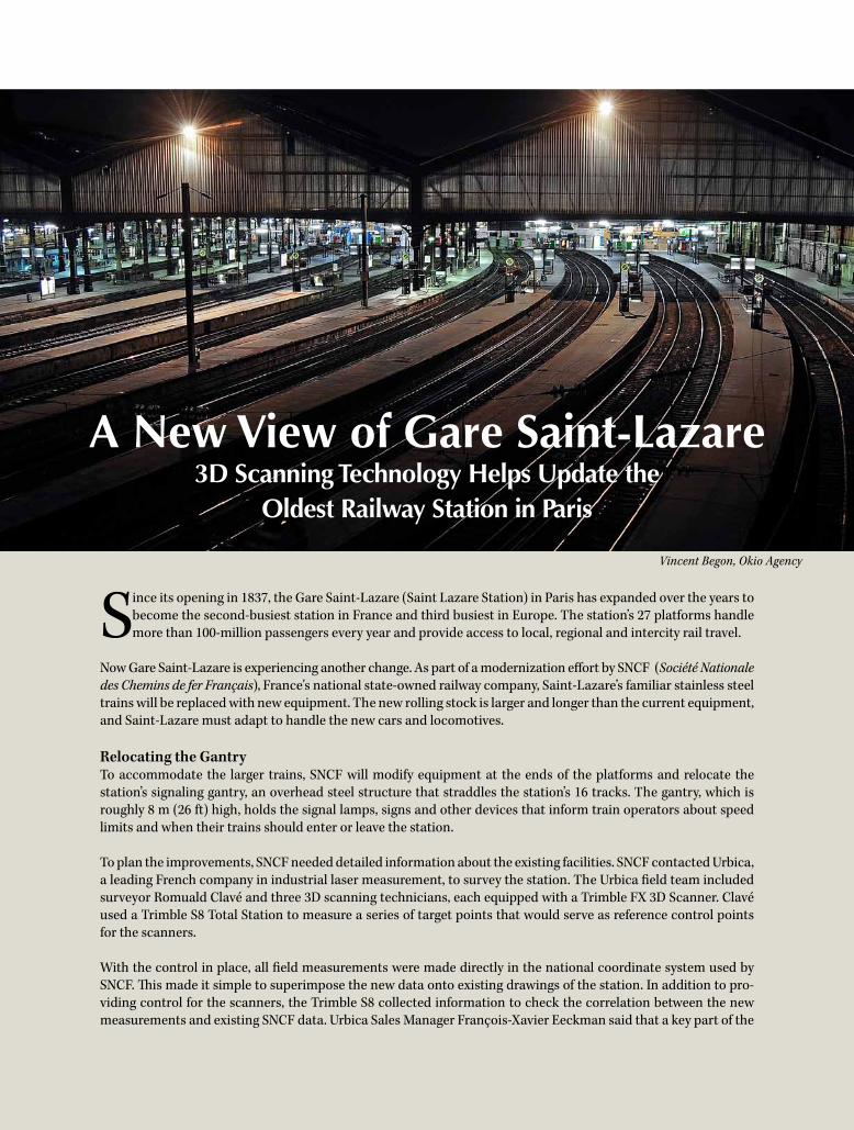
Since its opening in 1837, the Gare Saint-Lazare (Saint Lazare Station) in Paris has expanded over the years to become the second-busiest station in France and third busiest in Europe. The station’s 27 platforms handle more than 100-million passengers every year and provide access to local, regional and intercity rail travel.
Now Gare Saint-Lazare is experiencing another change. As part of a modernization effort by SNCF (Société Nationale des Chemins de fer Français), France's national state-owned railway company, Saint-Lazare’s familiar stainless steel trains will be replaced with new equipment. The new rolling stock is larger and longer than the current equipment, and Saint-Lazare must adapt to handle the new cars and locomotives.
Relocating the GantryTo accommodate the larger trains, SNCF will modify equipment at the ends of the platforms and relocate the station’s signaling gantry, an overhead steel structure that straddles the station’s 16 tracks. The gantry, which is roughly 8 m (26 ft) high, holds the signal lamps, signs and other devices that inform train operators about speed limits and when their trains should enter or leave the station.
To plan the improvements, SNCF needed detailed information about the existing facilities. SNCF contacted Urbica, a leading French company in industrial laser measurement, to survey the station. The Urbica field team included surveyor Romuald Clavé and three 3D scanning technicians, each equipped with a Trimble FX 3D Scanner. Clavé used a Trimble S8 Total Station to measure a series of target points that would serve as reference control points for the scanners.
With the control in place, all field measurements were made directly in the national coordinate system used by SNCF. This made it simple to superimpose the new data onto existing drawings of the station. In addition to pro-viding control for the scanners, the Trimble S8 collected information to check the correlation between the new measurements and existing SNCF data. Urbica Sales Manager François-Xavier Eeckman said that a key part of the
A New View of Gare Saint-Lazare 3D Scanning Technology Helps Update the
Oldest Railway Station in Paris
Vincent Begon, Okio Agency

-13- Technology&more; 2011-1
project’s success was the ability to integrate data from the Trimble FX 3D Scanners and the Trimble S8 Total Station. “It saved a surveyor from spending several additional hours on site,” he said.
Working LateBusy train traffic and safety concerns forced the team to work late at night. The team used one of the Trimble FX Scanners to conduct short-range scans of the gantry. The other two scanners collected data around the rails and platform. These scans extended approximately 60 m (200 ft) down the tracks. When measuring far down the tracks, the angle of incidence for the scanners’ laser beams became quite small. The Urbica team knew that the shallow
angles and poor lighting conditions might affect the precision of measurements to the tracks. To ensure that these difficult measurements met required precision, the technicians used the 2-pass configuration of their Trimble FX Scanners.
In two nights’ work at the station, Clavé and his team occupied 50 different instrument points. They collected roughly 300-million 3D points on a 5-mm (0.2 in) grid. Project specifications called for each point to have a precision of 20 mm (0.8 in) in horizontal and vertical com-ponents. According to Eeckman, the actual results were even better; most points had a deviation of roughly 10 mm (0.4 in).
3D Modeling and Video SimulationData from the scanners and total station were loaded into Trimble RealWorks® Software for processing and analysis. Urbica produced a complete point cloud and 3D view of the entire area. “Unlike a traditional survey, the scanner captures everything within its field of view,” Clavé said. “SNCF had the benefit of a 3D view of the catenaries, the platforms and their accessories. We provided them with measured positions for all the equipment in the area.”
Urbica used Trimble RealWorks to create simulations of the planned changes. The team combined measured data with dimensions of the future rolling stock to create simu-lated views of the lights and signals from the operator’s cab onboard the new trains. A video camera simulated a train operator’s head movements when reading the signals dis-played on the gantry. The simulation helped assess whether a train operator could see the signals, and checked that the catenaries would not obstruct his or her vision.
Eeckman noted that SNCF was pleased with the results, and will incorporate the 3D information into reports for its infrastructure management teams. The ability to incorporate detailed field information into simulations is a major benefit for SNCF’s processes for design, planning and construction.
See feature article in Professional Surveyor's February 2011 issue: www.profsurv.com

-14- Technology&more; 2011-1
Straight and Narrow
Digital photography is now ubiquitous and the users of survey and GIS data have come to expect ready ac-cess to photographic data. After all, when they read
the news online or look up information on Google Earth or Google Maps, they’re used to seeing pictures and videos that clarify difficult concepts. So when they browse survey fieldwork or a GIS, they assume that pictures will be readily available in that context as well.
In many situations photographs are often more useful than sketches or written descriptions. Images convey information about site conditions more accurately and quickly than any sketch; they also may provide better documentation for future use.
Sketches and physical field books will always have their place, but progressive consulting firms are finding ways to incorporate digital photography into their daily workflows. Trimble has been integrating still and video imagery into survey equipment for years, including in the groundbreak-ing Trimble VISION™ technology. But Trimble VISION is just one component of the company’s overall imagery strategy. Consider a few further examples in both current and newly released technology.
Built-in CamerasHigh-quality digital cameras are included in some Trimble equip-ment. The new Trimble TSC3 Controller, for example, includes
a 5-megapixel (5-MP) camera and an LED flash. This makes life easier for survey crews and GIS crews: rather than taking the time to write extensive notes or draw detailed sketches, now it is often possible to simply take a picture instead.
The Trimble Tablet Rugged PC comes standard with two cameras. The outward-facing, 2-MP camera is used to capture photos that support survey and GIS data. A good example would be a photo taken by a surveyor of an overflowing drainage structure while performing an as-built survey of a parking lot. The user-facing 1.3-MP camera enables live video conferencing and records crew-dictated notes. Both cameras shoot video, which is stored in .WMV files for easy sharing.
To take imagery one step further, the Trimble TSC3 and Trimble Tablet both have wireless Internet access. This improves real-time collaboration between field and office, especially when used with Trimble Access™ Software including AccessSync and Trimble Connected Community™ services. Crews can transmit measurements along with associated still images and video files. The office staff can analyze and pass back annotated images.
For instance, the office staff may recognize a key point that needs to be surveyed or a dimension that needs to be measured; they can easily illustrate this on the photo that was taken in the field only moments before. Potentially, this allows field crews to keep working in situations where they might previously have been forced to wait for office guidance.
Trimble Expands Use of ImageryNew Options Make it Easier and Faster to Incorporate Photography
into Survey Workflows

-15- Technology&more; 2011-1
Another advantage of Trimble’s imagery options is that they extend the reach of licensed profession-als. Field crews can directly consult with surveyors and engineers in the office; decisions can be made with fewer field visits and delays.
Use the Most Appropriate CameraThe onboard cameras in the Trimble Tablet and Trimble TSC3 Controller are appropriate for most survey tasks, but there are occasions when another camera may be more appropriate. Firms may want
to use cheaper cameras at times—if a crew is taking shots inside a sewer, for instance, it’s better to risk an inexpensive camera instead of critical equipment like a controller or a tablet. Conversely, higher-resolution
cameras may be needed when trying to capture details of complex environments, such as factories.
For these occasions, Trimble offers the 8-GB Eye-Fi Pro card, along with a software extension in Trimble Access that configures the Eye-Fi and integrates it into the data collection workflow. The
Eye-Fi Pro works with digital cameras that support SDHC cards.
To install the Eye-Fi Pro, users snap it into their camera and configure it with Trimble Access. Once installed, the user camera can transfer images to the Trimble Tablet or the Trimble TSC3 Controller. Wireless transfer is fast, even with large files. The Eye-Fi’s recommended range is
about 10 feet (3 m) from the tablet or controller, but images will transfer successfully at ranges up to 65 feet (20 m).
In addition to creating more options for the Trimble Tablet and Trimble TSC3, the Eye-Fi card effectively adds a camera to Trimble TSC2 Controllers with the revision 2, or later, Wi-Fi chip. Although Trimble TSC2 Controllers don’t have onboard cameras, with the Eye-Fi Pro implemented they can collect images as conveniently as the Trimble TSC3 Controllers.
Better Imagery WorkflowIncorporating photography has long been an Achilles’ heel of survey and GIS workflows. Typically, firms have relied on manual indexing schemes, combined with macros that automate office procedures. This method is prone to transcription errors so that photos occasionally get mislaid or assigned to the wrong coordinates.
To overcome this, Trimble has built image acquisition directly into Trimble Access. One or more photographic images can now be associated with any point gathered, along with more conventional attributes like description and location. Since the photo attribute is created at the same time the point is created and manual entry is eliminated, there is very little opportunity for photos to be mislabeled. Assigning a photo is basically as simple as taking a picture; the image comes in automatically and doesn’t even require text entry.
Trimble Business Center Software processes and archives Trimble Access job files and images from the Trimble Tablet, TSC3 and Eye-Fi. The user simply imports the Trimble Access job to a Trimble Business Center project, either directly from the data collector or remotely from the Trimble Connected Community. Trimble Business Center will grab the images from the data collector and store them in the project folder. The user can then navigate the project and view the images alongside the survey data. Additionally, Trimble Business Center has the ability to send the project to Google Earth, where survey data and images are displayed in tandem.
New technology is most effective when it is uncomplicated and works into existing work protocols. Thanks to integrated cameras, easy methods for using external cameras and thoughtful incorporation into existing workflows, surveyors should be able to expand the use of imagery without substantial change to their existing methods.
-16- Technology&more; 2011-1
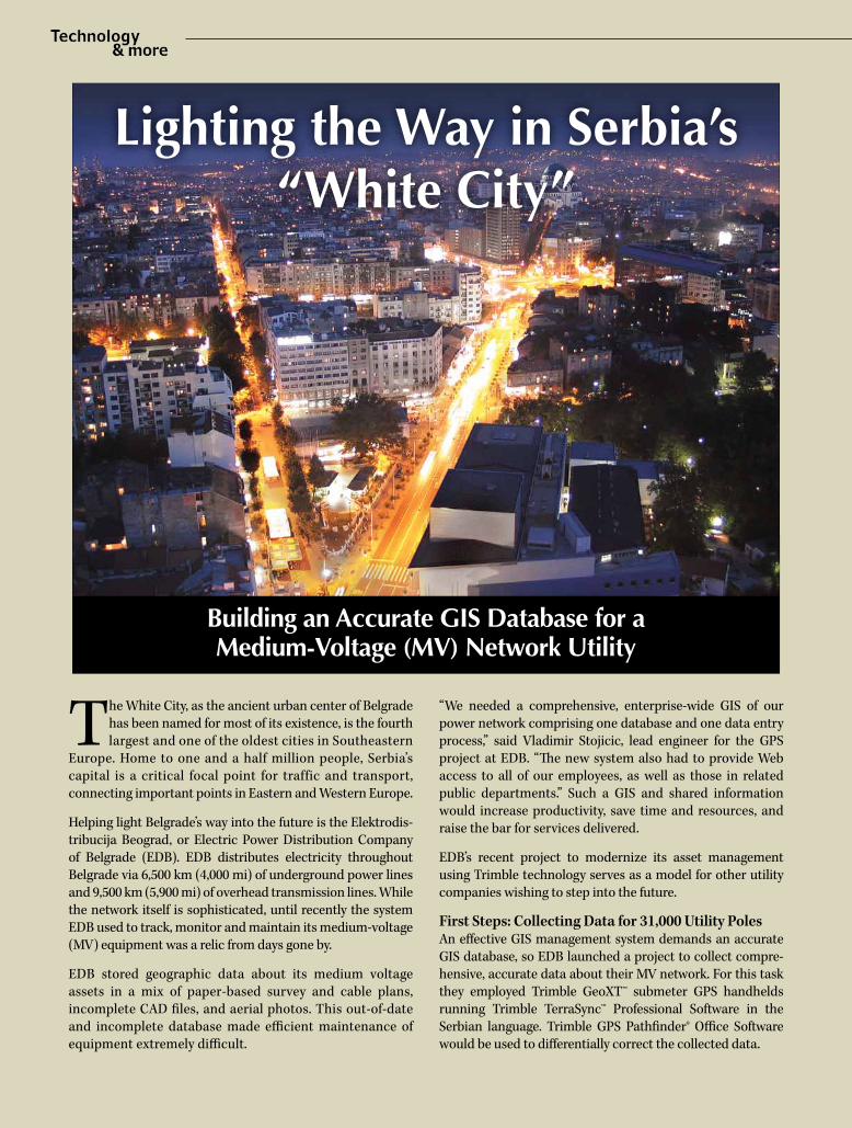
The White City, as the ancient urban center of Belgrade has been named for most of its existence, is the fourth largest and one of the oldest cities in Southeastern
Europe. Home to one and a half million people, Serbia’s capital is a critical focal point for traffic and transport, connecting important points in Eastern and Western Europe.
Helping light Belgrade’s way into the future is the Elektrodis-tribucija Beograd, or Electric Power Distribution Company of Belgrade (EDB). EDB distributes electricity throughout Belgrade via 6,500 km (4,000 mi) of underground power lines and 9,500 km (5,900 mi) of overhead transmission lines. While the network itself is sophisticated, until recently the system EDB used to track, monitor and maintain its medium-voltage (MV) equipment was a relic from days gone by.
EDB stored geographic data about its medium voltage assets in a mix of paper-based survey and cable plans, incomplete CAD files, and aerial photos. This out-of-date and incomplete database made efficient maintenance of equipment extremely difficult.
“We needed a comprehensive, enterprise-wide GIS of our power network comprising one database and one data entry process,” said Vladimir Stojicic, lead engineer for the GPS project at EDB. “The new system also had to provide Web access to all of our employees, as well as those in related public departments.” Such a GIS and shared information would increase productivity, save time and resources, and raise the bar for services delivered.
EDB’s recent project to modernize its asset management using Trimble technology serves as a model for other utility companies wishing to step into the future.
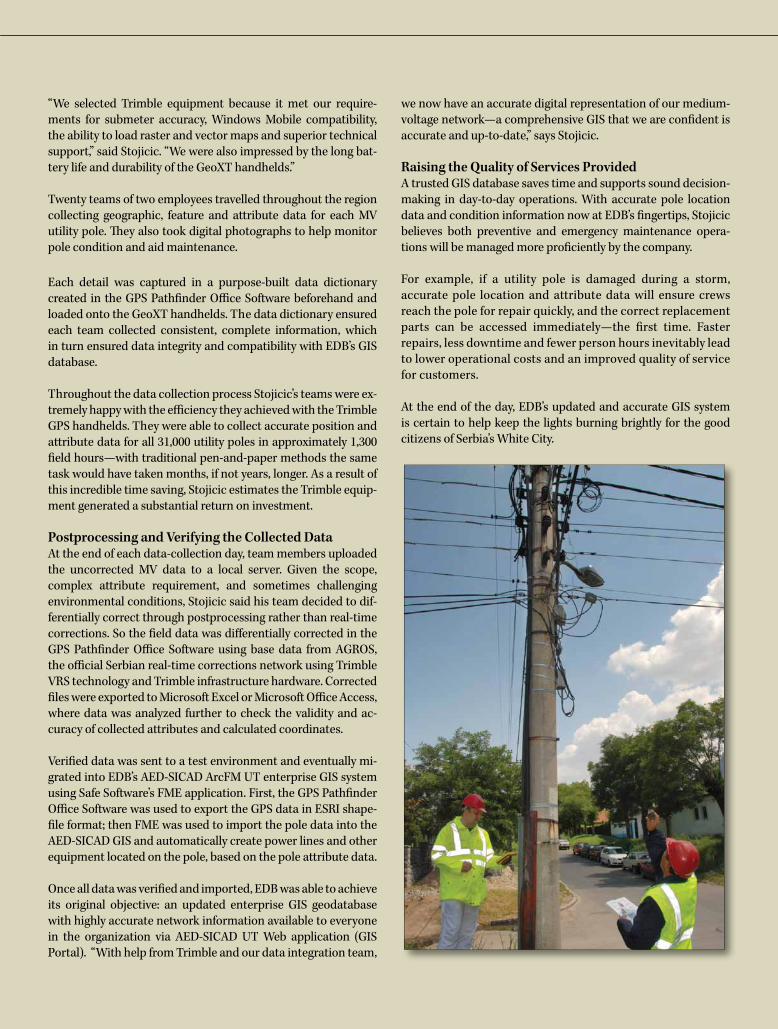
First Steps: Collecting Data for 31,000 Utility PolesAn effective GIS management system demands an accurate GIS database, so EDB launched a project to collect compre-hensive, accurate data about their MV network. For this task they employed Trimble GeoXT™ submeter GPS handhelds running Trimble TerraSync™ Professional Software in the Serbian language. Trimble GPS Pathfinder® Office Software would be used to differentially correct the collected data.
Lighting the Way in Serbia’s“White City”
Building an Accurate GIS Database for a Medium-Voltage (MV) Network Utility
-17- Technology&more; 2011-1
“We selected Trimble equipment because it met our require-ments for submeter accuracy, Windows Mobile compatibility, the ability to load raster and vector maps and superior technical support,” said Stojicic. “We were also impressed by the long bat-tery life and durability of the GeoXT handhelds.”
Twenty teams of two employees travelled throughout the region collecting geographic, feature and attribute data for each MV utility pole. They also took digital photographs to help monitor pole condition and aid maintenance.
Each detail was captured in a purpose-built data dictionary created in the GPS Pathfinder Office Software beforehand and loaded onto the GeoXT handhelds. The data dictionary ensured each team collected consistent, complete information, which in turn ensured data integrity and compatibility with EDB’s GIS database.
Throughout the data collection process Stojicic’s teams were ex-tremely happy with the efficiency they achieved with the Trimble GPS handhelds. They were able to collect accurate position and attribute data for all 31,000 utility poles in approximately 1,300 field hours—with traditional pen-and-paper methods the same task would have taken months, if not years, longer. As a result of this incredible time saving, Stojicic estimates the Trimble equip-ment generated a substantial return on investment.
Postprocessing and Verifying the Collected DataAt the end of each data-collection day, team members uploaded the uncorrected MV data to a local server. Given the scope, complex attribute requirement, and sometimes challenging environmental conditions, Stojicic said his team decided to dif-ferentially correct through postprocessing rather than real-time corrections. So the field data was differentially corrected in the GPS Pathfinder Office Software using base data from AGROS, the official Serbian real-time corrections network using Trimble VRS technology and Trimble infrastructure hardware. Corrected files were exported to Microsoft Excel or Microsoft Office Access, where data was analyzed further to check the validity and ac-curacy of collected attributes and calculated coordinates.
Verified data was sent to a test environment and eventually mi-grated into EDB’s AED-SICAD ArcFM UT enterprise GIS system using Safe Software’s FME application. First, the GPS Pathfinder Office Software was used to export the GPS data in ESRI shape-file format; then FME was used to import the pole data into the AED-SICAD GIS and automatically create power lines and other equipment located on the pole, based on the pole attribute data.
Once all data was verified and imported, EDB was able to achieve its original objective: an updated enterprise GIS geodatabase with highly accurate network information available to everyone in the organization via AED-SICAD UT Web application (GIS Portal). “With help from Trimble and our data integration team,
we now have an accurate digital representation of our medium-voltage network—a comprehensive GIS that we are confident is accurate and up-to-date,” says Stojicic.
Raising the Quality of Services ProvidedA trusted GIS database saves time and supports sound decision-making in day-to-day operations. With accurate pole location data and condition information now at EDB’s fingertips, Stojicic believes both preventive and emergency maintenance opera-tions will be managed more proficiently by the company.
For example, if a utility pole is damaged during a storm, accurate pole location and attribute data will ensure crews reach the pole for repair quickly, and the correct replacement parts can be accessed immediately—the first time. Faster repairs, less downtime and fewer person hours inevitably lead to lower operational costs and an improved quality of service for customers.
At the end of the day, EDB’s updated and accurate GIS system is certain to help keep the lights burning brightly for the good citizens of Serbia’s White City.

-18- Technology&more; 2011-1
Why measure mountains? Along with adventure, there are also very practical scientific, geodetic and public safety reasons.
While not the highest peak in the continental U.S., Washington state’s iconic 4,392 m (14,410 ft) Mount Rainier is one of the most brutal and unforgiving to climb—with an always-present risk of volcanic activity. The glacial peak of treacherous crevasses and unpredictable weather can defeat even experienced mountaineers, sometimes tragically: the mountain claims lives nearly every year.
As an active volcano, Mount Rainier’s height is of great interest and concern to surrounding communities; height changes could indicate volcanic activity that could release deadly walls of water and mud in what is known as a “lahar” mudslide.
In July 2010, the Land Surveyors Association of Washington (LSAW), using Trimble GNSS equipment and receiving data from the statewide Trimble VRS network, mounted their third expedition to measure the mountain. The U.S. Geological Survey (USGS) also provided gravity meters and sent a researcher to gather gravity readings, valuable for volcanic research and to provide more data for geoid models.
LSAW’s “Rainier 2010” was in stark contrast to their first expedition in 1988, which was the first measurement of a major mountain using GPS. With more than 140 volunteer climbers and support personnel, the 1988 team used the pioneering Trimble 4000 Series Receivers as part of a regional post-processed GPS campaign. A second expedition in 1999 used Trimble 4800 Receivers and 32 volunteers.
The Rainier 2010 team of 14 volunteers used lightweight Trimble R8 GNSS Receivers and Trimble TSC2 Controllers, as well as solar chargers, portable meteorological units and broadband cellular, which enabled rapid connection to the Washington State Reference Network.
Supported by a base camp team of six, two teams of five and three climbers, respectively, set off on different routes, gathering gravity data and performing GNSS observations along the way. A storm destroyed the tent of the three-man team on the mountain’s northwest face, forcing them to spend the second night in a snow cave. After descending the next day to get a new tent, they caught up to the team on the summit in one day: an amazing feat of climbing.
Once on the summit, the teams discovered that some of the original survey monuments had been stolen and the one remaining monument had been pried up several inches. Observations proceeded despite the continuing wild weather. A clever solution for dealing with the high winds was to place the R8 GNSS directly on the monument and brace it with rocks and snow. All climbers returned safely and the expedition is viewed as a great success.
With the observed height only a few inches higher than the previous expedi-tions, precisely the amount that the vandalized monument had been pried up, the LSAW issued a press release stating that the “published height of the mountain would remain the same,” with no outward signs of volcanic activity.
See feature article in American Surveyor's February 2011 issue: www.amerisurv.com
Measuring Mount Rainier
-19- Technology&more; 2011-1
Photo Contest
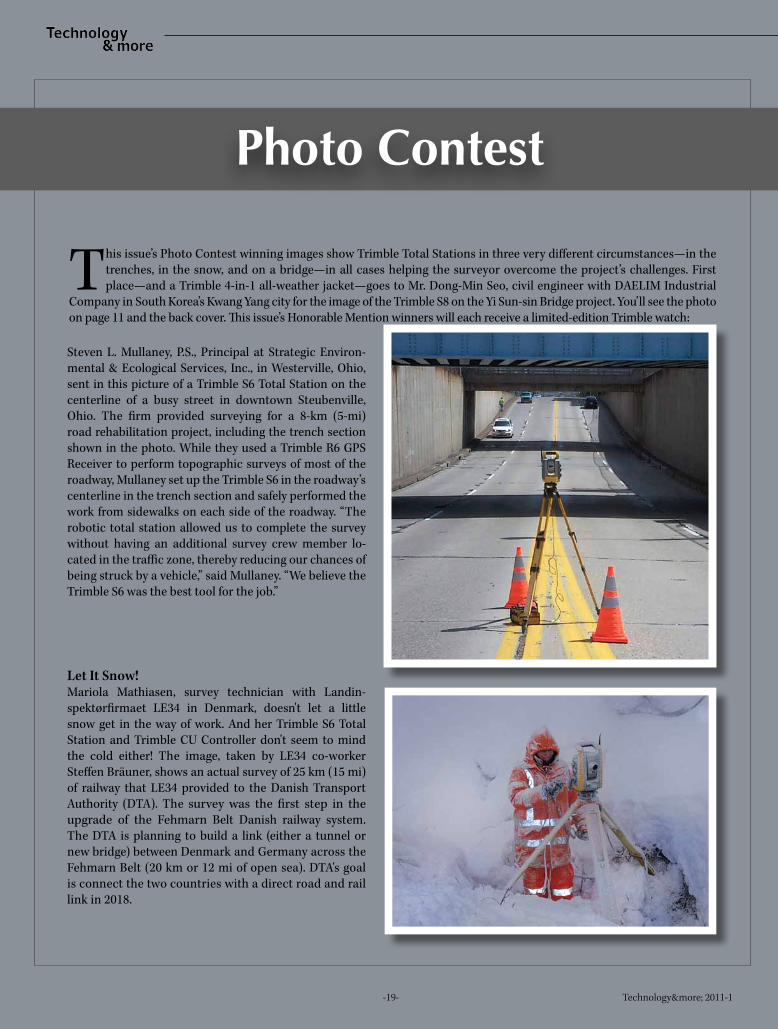
This issue’s Photo Contest winning images show Trimble Total Stations in three very different circumstances—in the trenches, in the snow, and on a bridge—in all cases helping the surveyor overcome the project’s challenges. First place—and a Trimble 4-in-1 all-weather jacket—goes to Mr. Dong-Min Seo, civil engineer with DAELIM Industrial
Company in South Korea’s Kwang Yang city for the image of the Trimble S8 on the Yi Sun-sin Bridge project. You’ll see the photo on page 11 and the back cover. This issue’s Honorable Mention winners will each receive a limited-edition Trimble watch:
Steven L. Mullaney, P.S., Principal at Strategic Environ-mental & Ecological Services, Inc., in Westerville, Ohio, sent in this picture of a Trimble S6 Total Station on the centerline of a busy street in downtown Steubenville, Ohio. The firm provided surveying for a 8-km (5-mi) road rehabilitation project, including the trench section shown in the photo. While they used a Trimble R6 GPS Receiver to perform topographic surveys of most of the roadway, Mullaney set up the Trimble S6 in the roadway’s centerline in the trench section and safely performed the work from sidewalks on each side of the roadway. “The robotic total station allowed us to complete the survey without having an additional survey crew member lo-cated in the traffic zone, thereby reducing our chances of being struck by a vehicle,” said Mullaney. “We believe the Trimble S6 was the best tool for the job.”
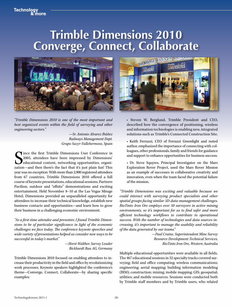
Let It Snow!Mariola Mathiasen, survey technician with Landin-spektørfirmaet LE34 in Denmark, doesn't let a little snow get in the way of work. And her Trimble S6 Total Station and Trimble CU Controller don't seem to mind the cold either! The image, taken by LE34 co-worker Steffen Bräuner, shows an actual survey of 25 km (15 mi) of railway that LE34 provided to the Danish Transport Authority (DTA). The survey was the first step in the upgrade of the Fehmarn Belt Danish railway system. The DTA is planning to build a link (either a tunnel or new bridge) between Denmark and Germany across the Fehmarn Belt (20 km or 12 mi of open sea). DTA's goal is connect the two countries with a direct road and rail link in 2018.
-20- Technology&more; 2011-1
Trimble Dimensions 2010Converge, Connect, Collaborate
"Trimble Dimensions 2010 is one of the most important and best organized events within the field of surveying and other engineering sectors."
—Sr. Antonio Alvarez IbáñezRailways Management Dept.
Grupo Sacyr-Vallehermoso, Spain
Since the first Trimble Dimensions User Conference in 2005, attendees have been impressed by Dimensions’ educational content, networking opportunities, organi-
zation—and then there’s the fact that it’s just plain fun! This year was no exception: With more than 2,900 registered attendees from 67 countries, Trimble Dimensions 2010 offered a full course of keynote presentations, educational sessions, Partners Pavilion, outdoor and “offsite” demonstrations and exciting entertainment. Held November 8–10 at the Las Vegas Mirage Hotel, Dimensions provided an unparalleled opportunity for attendees to increase their technical knowledge, establish new business contacts and opportunities—and learn how to grow their business in a challenging economic environment.
“As a first-time attendee and presenter, I found Trimble Dimen-sions to be of particular significance in light of the economic challenges we face today. The conference keynote speeches and wide variety of presentations helped us consider new ways to be successful in today’s market.”
—Horst Walther, Survey LeaderBickhardt Bau AG, Germany
Trimble Dimensions 2010 focused on enabling attendees to in-crease their productivity in the field and office by revolutionizing work processes. Keynote speakers highlighted the conference’s theme—Converge, Connect, Collaborate—by sharing specific examples:
• Steven W. Berglund, Trimble President and CEO, described how the convergence of positioning, wireless and information technologies is enabling new, integrated solutions such as Trimble’s Connected Construction Site.
• Keith Ferrazzi, CEO of Ferrazzi Greenlight and noted author, emphasized the importance of connecting with col-leagues, other professionals, family and friends for guidance and support to enhance opportunities for business success.
• Dr. Steve Squyres, Principal Investigator on the Mars Exploration Rover Project, used the Mars Rover Mission as an example of successes in collaborative creativity and innovation, even when the team faced the potential failure of the mission.
“Trimble Dimensions was exciting and valuable because we could interact with surveying product specialists and other spatial groups facing similar 3D-data-management challenges. RioTinto Iron Ore employs over 50 surveyors in active mining environments, so it’s important for us to find safer and more efficient technology workflows to contribute to operational success. With the number of technologies and data sources in-creasing, it’s important to manage the usability and reliability of the data generated by our teams.”
—Paul Craine, Superintendent Mine SurveyResource Development Technical Services,
RioTinto Iron Ore, Western Australia
Multiple educational opportunities were available in all fields. The 467 educational sessions in 32 specialty tracks covered sur-veying; field and office computing; wireless communications; engineering; aerial mapping; building information modeling (BIM); construction; mining; mobile mapping; GIS; geospatial; utilities; and mobile resources. Sessions were conducted both by Trimble staff members and by Trimble users, who related
-21- Technology&more; 2011-1
their own field experiences. Follow-up Q&A sessions often stimulated vigorous discussions and more knowledge sharing.
“Trimble Dimensions is a fantastic event! It’s a great oppor-tunity to discuss the latest news of the industry and to share project experiences with colleagues. The number of interesting presentations is so huge it’s hard to attend just the sessions you had planned. I thank Trimble so much for this amazing event.”
—Mr. Sergey SkorokhvatovHead of Photogrammetry and Remote Sensing Department,
SE Mosgorgeotrest, Russia
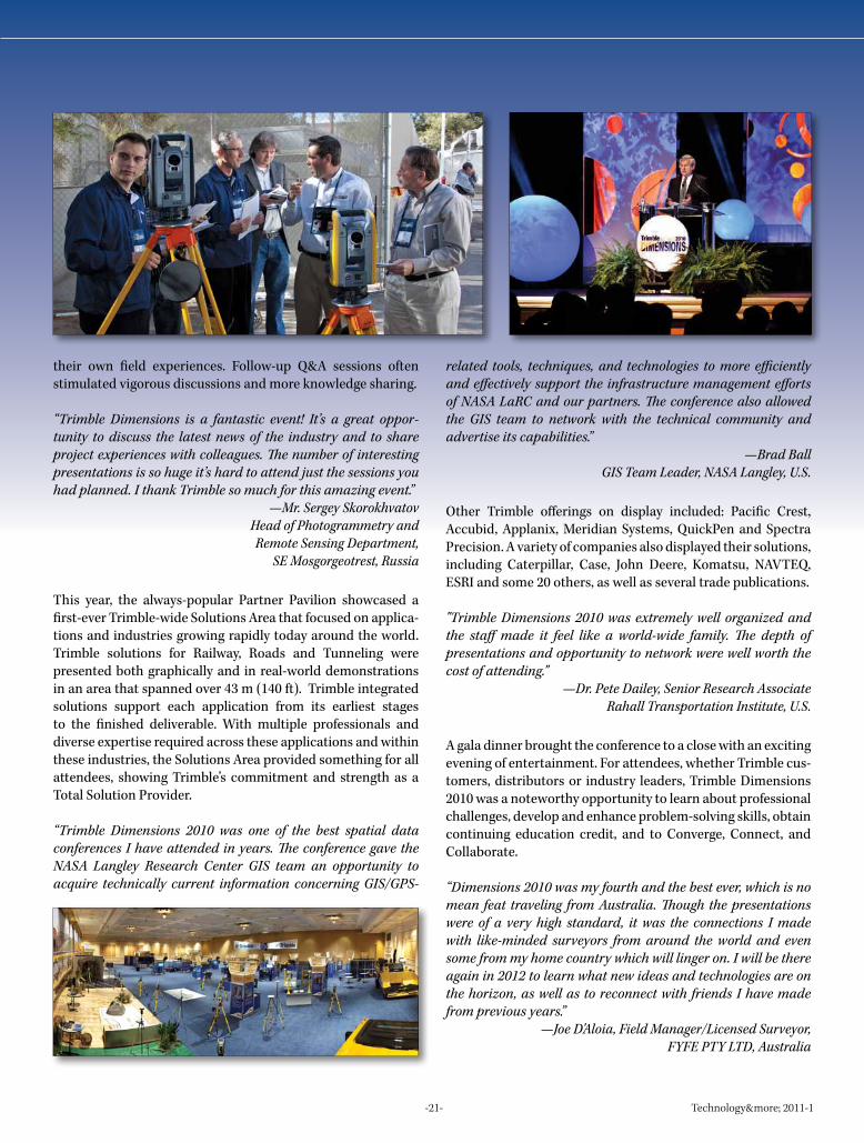
This year, the always-popular Partner Pavilion showcased a first-ever Trimble-wide Solutions Area that focused on applica-tions and industries growing rapidly today around the world. Trimble solutions for Railway, Roads and Tunneling were presented both graphically and in real-world demonstrations in an area that spanned over 43 m (140 ft). Trimble integrated solutions support each application from its earliest stages to the finished deliverable. With multiple professionals and diverse expertise required across these applications and within these industries, the Solutions Area provided something for all attendees, showing Trimble’s commitment and strength as a Total Solution Provider.
“Trimble Dimensions 2010 was one of the best spatial data conferences I have attended in years. The conference gave the NASA Langley Research Center GIS team an opportunity to acquire technically current information concerning GIS/GPS-
related tools, techniques, and technologies to more efficiently and effectively support the infrastructure management efforts of NASA LaRC and our partners. The conference also allowed the GIS team to network with the technical community and advertise its capabilities.”
—Brad BallGIS Team Leader, NASA Langley, U.S.
Other Trimble offerings on display included: Pacific Crest, Accubid, Applanix, Meridian Systems, QuickPen and Spectra Precision. A variety of companies also displayed their solutions, including Caterpillar, Case, John Deere, Komatsu, NAVTEQ, ESRI and some 20 others, as well as several trade publications.
"Trimble Dimensions 2010 was extremely well organized and the staff made it feel like a world-wide family. The depth of presentations and opportunity to network were well worth the cost of attending."
—Dr. Pete Dailey, Senior Research AssociateRahall Transportation Institute, U.S.
A gala dinner brought the conference to a close with an exciting evening of entertainment. For attendees, whether Trimble cus-tomers, distributors or industry leaders, Trimble Dimensions 2010 was a noteworthy opportunity to learn about professional challenges, develop and enhance problem-solving skills, obtain continuing education credit, and to Converge, Connect, and Collaborate.
“Dimensions 2010 was my fourth and the best ever, which is no mean feat traveling from Australia. Though the presentations were of a very high standard, it was the connections I made with like-minded surveyors from around the world and even some from my home country which will linger on. I will be there again in 2012 to learn what new ideas and technologies are on the horizon, as well as to reconnect with friends I have made from previous years.”
—Joe D'Aloia, Field Manager/Licensed Surveyor, FYFE PTY LTD, Australia
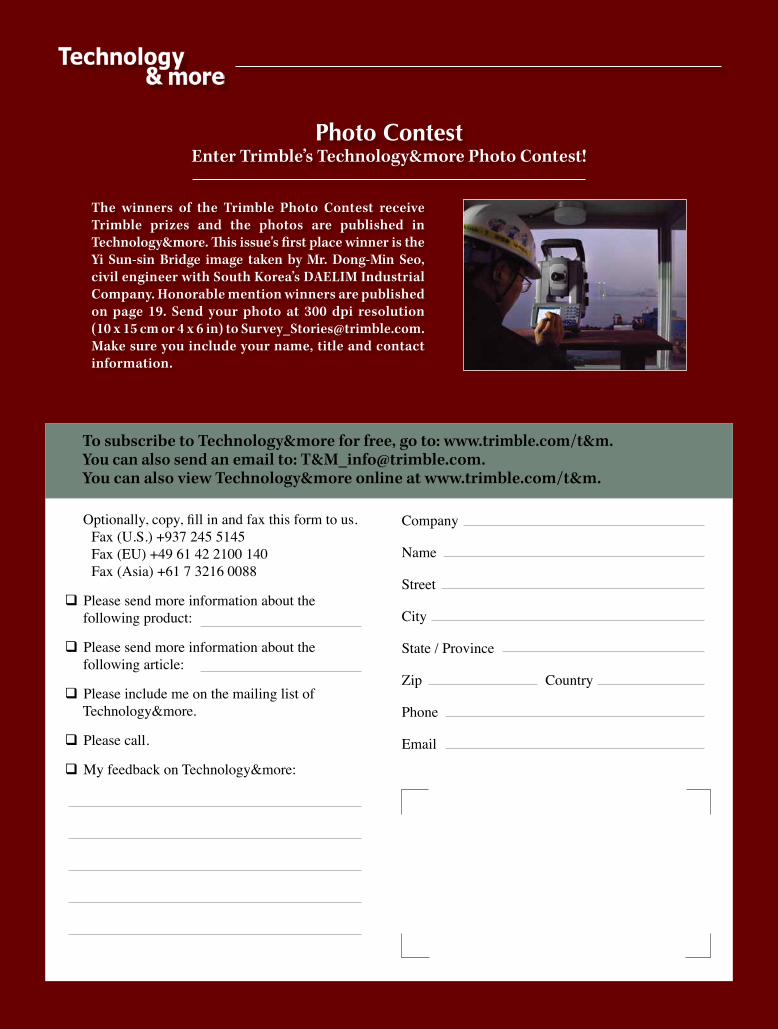
Photo ContestEnter Trimble’s Technology&more Photo Contest!
Optionally, copy, fill in and fax this form to us. Fax (U.S.) +937 245 5145 Fax (EU) +49 61 42 2100 140 Fax (Asia) +61 7 3216 0088
q Please send more information about the following product:
q Please send more information about the following article:
q Please include me on the mailing list of Technology&more.
q Please call.
q My feedback on Technology&more:
To subscribe to Technology&more for free, go to: www.trimble.com/t&m.You can also send an email to: T&[email protected] can also view Technology&more online at www.trimble.com/t&m.
Company
Name
Street
City
State / Province
Zip Country
Phone
The winners of the Trimble Photo Contest receive Trimble prizes and the photos are published in Technology&more. This issue's first place winner is the Yi Sun-sin Bridge image taken by Mr. Dong-Min Seo, civil engineer with South Korea’s DAELIM Industrial Company. Honorable mention winners are published on page 19. Send your photo at 300 dpi resolution (10 x 15 cm or 4 x 6 in) to [email protected]. Make sure you include your name, title and contact information.