Embed Size (px)
Citation preview

NASA
Technical
Memorandum
NASA TM-lOB453
,00
N 0',0 el
em n) r,..I ,,-- ..I-
"4" U 00, C o
o',em
0
ROOT-SUM-SQUARE STRUCTURAL STRENGTHVERIFICATION APPROACH
By Henry M. Lee
Structures and Dynamics Laboratory
Science and Engineering Directorate
April 1994
NASANational Aeronautics andSpace Administration
George C. Marshall Space Flight Center
MSFC - Form 3190 (Rev. Mey 1983)
https://ntrs.nasa.gov/search.jsp?R=19940025701 2018-07-28T16:19:32+00:00Z


REPORT DOCUMENTATION PAGE Fo.. A_=ov_dOMB No. 0704-0188
Pubhc reporting burden for this collection of information Js estimated to aver_je 1 hour per rest_onse, including the time for reviewing instructions, searching existing data sources.
cgol_heflng an d mamta!ning t.he data needed_ and coml_et!ng a_l reviewing the collection of information. Send comments regarding this burden estimate or any other ast_ect of this
o; intocmatlO¢l, inclUOlng $lKj_jeStlO_ for reducing this burden, to Washmgton Headquarters Services, Directorate for Information Operations and RepOrts, ! 215 Jefferson
Davis Highway, Suite 1204, Adinglton. VA 22202-4302, and to the Office of Management and Budget, Paperwork Reduction Project (0704-0188), Washington, DC 20503.
1. AGENCY USE ONLY (Leave blank) 2. REPORT DATE 3. REPORT TYPE AND DATES COVERED
April 1994 Technical Memorandum
4. TITLE AND SUBTITLE 5. FUNDING NUMBERS
Root-Sum-Square Structural Strength Verification Approach
6. AUTHOR(S)
H.M.
7. PERFORMING ORGANIZATION NAME(S) AND ADDRESS(ES) 8. PERFORMING ORGANIZATIONREPORT NUMBER
George C. Marshall Space Flight Center
Marshall Space Flight Center, Alabama 35812
9. SPONSORING/MONITORING AGENCY NAME(S) AND ADDRESS(ES) 10. SPONSORING/MONITORINGAGENCY REPORT NUMBER
National Aeronautics and Space AdministrationWashington, De 20546 NASA TM- 10 8 4 5 3
11. SUPPLEMENTARY NOTES
Prepared by Structures and Dynamics Laboratory, Science and Engineenng Directorate
12a. DISTRIBUTION/ AVAILABILITYSTATEMENT
Unclassified--Unlimited
13. ABSTRACT (Maximum 200 words)
12b. DISTRIBUTION CODE
Utilizing a proposed fixture design or some variation thereof, this report presents a verification
approach to strength test space flight payload components, electronics boxes, mechanisms, lines,
fittings, etc., which traditionally do not lend themselves to classical static loading. The fLxture, througt
use of ordered Euler rotation angles derived herein, can be mounted on existing vibration shakers and
can provide an innovative method of applying single axis flight load vectors. The versatile fixture
effectively loads protoflight or prototype components in all three axes simultaneously by use of a
sinusoidal burst of desired magnitude at less than one-third the first resonant frequency. Cost savings
along with improved hardware confidence are shown to be the potential, with the end product being ar
efficient way to verify experiment hardware for both random vibration and strength.
14. SUBJECT TERMS
root-sum-square (RSS), strength test verification, ordered Euler rotations
17. SECURITY CLASSIFICATION 18. SECURITY CLASSIFICATION 19. SECURITY CLAS'SIFICATION
OF REPORT OF THIS PAGE OF ABSTRACT
Unclassified Unclassified UnclassifiedNSN 7540-0'f -280-5500
15. NUMBER OF PAGES
4816. PRICE CODE
NTIS
20. LIMITATION OF ABSTRACT
UnlimitedStandard Form 298 (Rev 2-89)


TABLE OF CONTENTS
INTRODUCTION .........................................................................................................................
POTENTIAL FIXTURE DESIGN ................................................................................................
ORDERED EULER ROTATION FORMULAS ...........................................................................
CALCULATION OF ACTUAL LOAD SET ................................................................................
CONCLUSIONS ............................................................................................................................
REFERENCE .................................................................................................................................
APPENDIX A - ADDITIONAL FIXTURE VIEWS ....................................................................
APPENDIX B - STRENGTH ANALYSIS ...................................................................................
Page1
2
13
18
21
23
25
31
_GE WLANK _ F'N._L_)
.°o
111

LIST OF ILLUSTRATIONS
Figure
1.
2.
3.
4.
5.
6.
7.
8.
9.
10.
11.
12.
Title
RSS loads fixture concept ............................................................................................
Exploded view ..............................................................................................................
Oxy position base ..........................................................................................................
Oxy position clamp .......................................................................................................
Or z position fixture .......................................................................................................
Oyz position fixture--plan view ...................................................................................
Bushing block ..............................................................................................................
Oyz and Oxz position shear bar ......................................................................................
Oxz position fixture .......................................................................................................
Oxz position fixture--plan view ...................................................................................
Component mount fixture ............................................................................................
Hardware orientation ....................................................................................................
Page
2
3
4
5
6
7
8
9
10
11
12
20
iv

TECHNICAL MEMORANDUM
ROOT-SUM-SQUARE STRUCTURAL STRENGTH VERIFICATION APPROACH
INTRODUCTION
At present the vast majority of payload experiments, electronic boxes, control packages, mech-
anisms, etc., designed for space flight are random vibration tested one axis at a time (x,y,z). In the
majority of these cases, no strength verification testing is done because these items generally do not
easily lend themselves to classical static testing. Such testing, when feasible, involves applying static
loadings to the proposed flight hardware in all three axes at the same time. Unless a centrifuge facility isavailable, there is not another clear engineering solution. For this reason, hardware in the categories out-
lined above are generally strength verified by analysis only. This fact has somewhat forced many of theNASA field Centers to utilize what is commonly referred to as the controversial "untested factors of
safety." At MSFC these factors are 1.25 and 2.00 for yield and ultimate, respectively. They are even
larger at some other Centers. Strength testing along with analysis has always been the preferred methodof verification for space flight hardware, not only from a requirements standpoint but also because it is a
more secure engineering approach. If tested factors could be used at MSFC, then yield and ultimatewould be 1.10 and 1.4, respectively. Several other NASA Centers have partially circumvented the prob-
lem by attempting to strength verify all such flight hardware on the vibration shake table, but again they
are unable to place loads on their components in all three axes simultaneously. They must settle for aform of verification involving either greater than limit load random vibration testing or low frequency
sinusoid testing one axis at a time (x,y,z). A more exact, yet practical solution is certainly a desirable
goal.
The approach proposed in this report involves manufacturing what will be called a "root-sum-
square (RSS) loads fixture" (fig. 1). The versatile fixture would be built and mounted on existing ver-
tically and horizontally oriented vibration shake tables. It would provide the capability of accomplishing
ordered Euler angle rotations such that a single expected flight load vector can be applied to protoflight
or prototype hardware in all three axes with one test. Thus, the term RSS, which refers to root-sum-
square as defined by the equation
RSS acceleration = _/A_+Ar+Az2 2 ,
is used to describe the proposed fixture. At MSFC the RSS acceleration could be the summation of
single axis random and the low frequency transient loads as described in NASA technical memorandumTM-86538, l or as dictated by program requirements. This fixture could be used prior to the normal ran-
dom vibration verification testing of the National Space Transportation System (NSTS) or the expend-
able launch vehicle (ELV) payloads, electronic boxes, experiments, control packages, mechanisms,
lines, and valves. It will be shown that by calculating a typical single RSS vector flight load set, apply-
ing a test factor of >1.20 (per NSTS 14046 requirement) for flight hardware and >1.40 for protoflight,
and subjecting the component to a sinusoidal burst of that magnitude at <1/3 the first resonant frequency,
the component could be considered strength verified by both analysis and test. If desired, strain gaugescould be secured to key areas on the structure so that correlation with analytical models is accomplished.
In addition, historically MSFC has found that it always learns more about the hardware when it is sub-
jected to testing rather than analysis only.

/
COMPONENT
VIBRATION SHAKE TABLE
Figure 1. RSS loads fixture concept.
POTENTIAL FIXTURE DESIGN
Figures 2 through 11 depict engineering sketches of how such a device might look. Additional
views of the fixture are shown in appendix A. The primary capability feature is that a componentmounted to this fixture could be rotated about all three axes until the desired single acceleration vector is
established. This fact alone makes it possible to statically load the component in all three axes simul-
taneously with one test.
2

FRONT VIEW
I
I
SIDE VIEW
Component Mount Rxture
I I
, Bushing Block
I
xz Position Rxture
Shear Bars
I
I
I
.!
!
Bushing Block
I
, Clamps
exy Position Base r--" ff_-_ _ Shear Bars! I
' Z _ '! !
- (I '.J I I iI
! II I
I II II I
v
Figure 2. Exploded view.

I I
I
j I!
//
Witnessed & Understood bv me.
Ii
t
To Page No._
rf
_.o[_
Figure 3. Oxy position base.
4

I::::!Y,TtIRB. CON,C__PTProject No.
Book No.
,ssed & Understood by me. Date
Figure 4. Oxy position clamp.

I I
r
i I i
!
Project No.Book No.
i 1 t i ifE
I I
i ;
I i
i
' Witnessed & Understood by me.I Date Ilnvented by t-_d_tl_y IVt,.
Figure 5. Oyz position fixture.
To Page No._

71TLE R_ FiY,TL[__ CA_tC_F'FProject No.
Book No.
I
I
i
I
i !
I ! I
i
Ii
I
I
Witnessed & Understood by me.
\\
I
/I
)ate Date
,8/93
t J
.To Page No._
tt
ToL_+.o/o
Figure 6. Oyz position fixture--plan view.
! I !
TITLE _%_
From Page No._ !i
Project No.Book No.
N
Witnessed & Understood by me. )ate Date
To Page No._
__.010"
Figure 7. Bushing block.
TITLE R._._ _ [_'_'_ cc c. PTProject No.
Book No.__
I
[00
_ !;.5o
To Page No.__
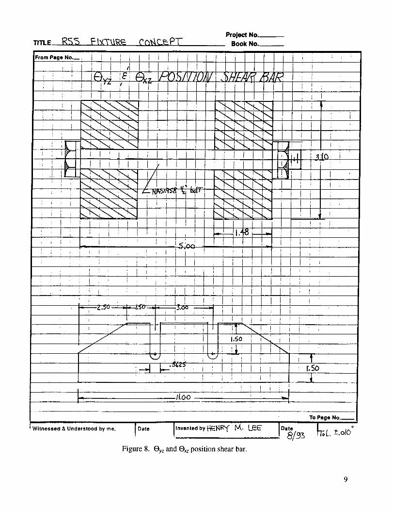
Figure 8. Oyz and Oxz position shear bar.

TITLE _ f: _
From Page No._
ii I
I
; i
; i
1 4i 1
L
; i
I¢,a
w
i
o
o6
t
I,I
--_-!
Prole_, NO.Book No._
I li
'o
• .
O
,_li_(ne_sed g., Understood by me.
kn
! Date
Figure 9.
O
by lr_/_'_ _/k. L._
Oxz position fixture.
Date
To Page No.-
t/__.oto
10

I I I
TITLE ("_-_S Ft_.TU.RE C._N{'EPT"Project No.
Book No.
From Page No.__ :
i
, i
i
,i,_o_i_.i__
Witnessed & Understood by me.
Date Ilnvented by _E_I _ _. Lf_._
Figure 10. Oxz position fixture--plan view.
To Page No._
[Date [7_L. -.Ot_,
!e/ 5 I
11

i I !
I
! Witnessed & Unaerstood by me.)ate
Figure l 1. Component mount fixture.
12

In orderto effectivelydesignanytestfixture,requirementsmustfirst beinstituted.Thefollowingdesignrequirementswereplacedon thepotentialtesttool:
1. Theexperimentor componentto bestrengthtestedmustweighnomorethan100lb.
2. ThemaximumRSSaccelerationloadfactormustbenomorethan50G's.
3. Theexperimentor componentto betestedmusthaveacenterof gravitynomorethan32 inchesabovetheshakerattachplate.
4. The factorof safetyagainstultfmateshallbe5.0.
5. Thefactor of safetyagainstyield shallbe3.0.
In orderto provethatthedesignis a structurallyfeasibleone,astressanalysisis accomplishedutilizing thedesignrequirementsasinput.SuchananalysishasbeenperformedandcanbereviewedinappendixB of thisreport.Oncethedesignactuallybecomeshardware,it mustalsobesubjectedto someform of testverification.Oneeffectivewayto dothis is asfollows:
1. Staticproof testthefixture to two timesthedesignrequirementswhile it is in thefullyextendedposition(Oxy= Oyz = Oxz = 0.0).
2. Perform a sine sweep from 5 to 50 Hz at 1 octave per minute to 0.25 G's in each axis with a
100-1b rigid mass mounted to the fixture while in its fully extended position.
3. Sine burst test the fixture and rigid mass at 1]3 the first resonant frequency. This would bedone with the rigid mass and fully extended fixture mounted to a horizontal shake table.
4. Sine burst test as above but in several other rotated positions.
ORDERED EULER ROTATION FORMULAS
The calculation of an RSS single load vector is certainly an elementary accomplishment, how-ever, just knowing the magnitude and direction of this vector is not enough. One must determine the
three ordered angle rotations it will take to place the hardware in the right location such that the compo-nent to be strength tested is loaded as desired. The following pages effectively show how these rotations
determine the position of any point on the component. The three transformations allow us to develop
three equations. These equations solve for the ordered rotation angles (Oxy,Oyz,O_) in terms of the
desired final apparent angles (Wxy, Wyz,_'xz) which were set when the RSS vector is calculated.
13

I. ROTATION TRANSFORMATION [X to Y about Z]:
t
Z,Z' =__Y
®xy
X
c°s° -sinO ol x' = sin 0_ cos Oxy 0 | _ Y_
0 0 1] _z/
14

II. ROTATION TRANSFORMATION:[Y' to Z' about Y7
l|
l
tJ
|
[!oY" = cos Or zZ'
sin Or zo ] [x'q
-sin Or z _Y"_
cos Or z _Z"/
15

III. TRANSFORMATION ROTATION: [X" to Z" about Y']
Xtl X|B9
y|lll yIIt|
gll
tWV
X")PP
Z'"
COS O xz
0
sin O xz
0 -sinOxz][X"" _o I_Y"_ •
0 "'Z'"]0 cos O_z J t
16

IV. MATRIX MULTIPLICATION:
Y'"?[ I. J[ II. Jl. III. J_Z'"}
which becomes
(!}_z'"]
This transformation matrix [T] relates the initial coordinates of a point (X, Y, Z) to the final
coordinates (X'", Y'", Z") after three consecutive ordered rotations O_y, Oyz,Oxz.
V. DETERMINATION OF ORDERED ROTATION ANGLES:
A. sin Oxy cos Oxz- cos O_y sin _)yz sin Oxz = (tan tI"xy)(COSOxy COS Oxz + sin Oxy sin Or zsin Oxz) ,
B. +sin Oxy sin Oxz + cos Oxy sin Oy z cos Oxz = (tan U?yz)(COSOr z cos Oxz) ,
C. +cos Oxy sin Oxz - sin Oxy sin Oy z cos Oxz = (tan Wxz)(cos Oy z cos Oxz) •
Three equations and three unknowns (Oxy, Oy z, Ox z) which can be solved through trigonometric sub-stitution:
(tan qJxz)(tan _Fyz)+(tan "Fxy)(tan "erz) 2+(tan ")'xy)
tan Oxy = (tan Wxz)a+(tan qJxy)(tan Wyz)(tan "Fxz)+ 1 ' Equation 1
(tan _'yz)-(tan tl'xz)(tan Oxy)
tan Oy z = (tan Oxy)(Sin Oxy)+(cos Oxy) 'Equation 2
(tan '4'/z)(cos Orz)
tan O_z = (cos 0 7) + (tan Oxy)(sin Oyz), Equation 3where:
Wxy = apparent angle that acceleration vector makes in X-Y plane
tt'y z = apparent angle that acceleration vector makes in Y-Z plane
Wxz = apparent angle that acceleration vector makes in X-Z plane
Oxy = unknown Euler angle - rotation about Z axis
Oyz = unknown Euler angle - rotation about X' axis
Oxz = unknown Euler angle - rotation about Y" axis.
17

¥
Vector
_yz_X
lVector Z vector Z
_¥
CALCULATION OF ACTUAL LOAD SET
The load set generated in this section assumes that the MSFC single-axis random philosophy is
being used to establish strength loadings for flight hardware. This philosophy is less conservative thansome other accepted approaches, but has been proven to be realistic for NSTS hardware in the launch
phase. The drawback to the philosophy is that a large number of load cases will be generated for thestrength analysis. Other more conservative ways that produce fewer load cases may become more attrac-
tive in the future when strength testing is feasible as with this fixture.
RSS SINGLE VECTOR FLIGHT LOAD SET
AXIS OUASI-STATIC RANDOM
LOAD LOAD
X -I-S1 +-t-R1
Y -+$2 W-t-R2
Z +$3 +-_R3
There are 24 possible load cases using this standard set of loads as described in NASA TM-
86538 "Design and Verification Guidelines for Vibroacoustic and Transient Environments." Utilizing avibration shake table reduces this to 12 cases, since 2 cases are accomplished at the same time (i.e.;
[(SI+R1), $2, $3] and [-(SI+R1),-$2.-$3] ).
18

Anotherway of potentiallyreducingtheloadcasesin thesetwouldbeto performapretestanalysisanddeterminethemostcritical loadsfor thespecifichardware.For typical experimentsandelectronicboxes,only four loadcaseswouldgenerallybeneeded.This is becausethepeakloadingwilloccuron thefour comers.Thesetuptimein anycasewouldbeminimal andshouldtakenomorethan1to 2 daysto do4 to 12cases.
Assumingthata verticalshaketableis utilizedfor thesetests,theapparentangles(Wxy,Wyz,Wxz)mustbealteredto align theaccelerationvectorwith theshakeraxis(Z). Thatmeansthat therotationvector,asshownin figure 12,is differentfrom theaccelerationvector.This is easilydoneby puttingaminus(-) signin front of theX and Y coordinates. The generic set of load cases for any hardware isshown below.
where:
_XJxy =
GENERIC LOAD SET
LOAD CASE X Y Z
1 +(Sl+Rx) +$2 +$3
2 +($1 +R1 ) +$2 -$3
3 +(SI+R1) -$2 +$3
4 +(SI+R1) -$2 -$3
5 +S 1 +(S2+R2) +$3
6 +$1 +($2+R2) -$3
7 +$1 -($2+R2) +$3
8 +S 1 -($2+R2) -$3
9 +S1 +$2
10 +S1 -I-$2
11 +$1 -$2
12 +$1 -$2
CASES 1-4
$2tan-i ((SI+R1))
CASES 5-8
tan-l[(S2+R2)l
+($3+R3)
-($3+R3)
+($3+R3)
-($3+R3)
CASES 9-12
g[ly z =
S2
kldXZ "--
[(S,+R1)I
tan-l , S3 1Sl
19

X
0
Z0m
,<
0mm
I!= o
m m
C
• x Q.u mu E
_ 0u umO
on- C _o
O.,-4
o_
2O

CONCLUSIONS
This report has sought to present a possible scenario by which space flight hardware and associ-
ated components, which are not easily static strength tested, can be tested. The approach includes the
design of a fixture which can be attached to vibration shake tables and can be rotated about all three axes
such that any acceleration load vector can be achieved. Also outlined are the formulas necessary to cal-
culate the magnitude of the three ordered Euler angles used to align the test component such that a single
RSS load factor may be applied. In addition, a sample load set is generated for a typical component to be
test verified per the MSFC philosophy. The fixture, too, is shown to be verified by analysis, and a sug-
gested approach to test verification is also'presented.
Though it would not be a major impact, this approach could reduce the weight required to
develop experiments, since the ultimate factor of safety would be reduced from 2.0 to 1.4. For primary
load carrying members, it could be a 30-percent weight savings which translates to material costs and
overall payload weight reduction. Secondly, because of intercenter controversy over whether experiment
hardware should require strength testing in order to be fully verified, and whether the so called "untested
factors of safety" should be used, a significant amount of engineering time could be saved through a
consistent utilization of tested factors of safety with this approach. The Rotator Chair developed by
Johnson Space Center (JSC) for the IML-1 Spacelab mission absorbed some 300 engineering man-hoursbefore resolution of a random vibration test verification approach. Other NASA Centers such as
Goddard Space Flight Center (GSFC) and the Jet Propulsion Laboratory (JPL) are continually faced with
the problem of strength test verification for such components. As stated previously, they have resorted to
methods such as random vibration over-testing (one axis at a time), below resonance sine burst over-tests (one axis at a time), and, in a few cases, expensive centrifuge testing. The proposed methodology
would bring a unification to the entire agency on how strength testing is accomplished for hardware that
is difficult to apply static loadings to such as electronic boxes, experiments, control packages, mech-anisms, lines, and valves, etc. The real beauty of the proposed RSS loads fixture testing philosophy is
that random vibration testing is already a verification requirement for most of this hardware. The RSS
loads fixture will attach to existing vibration shake tables, and testing would be accomplished during
planned random testing with almost no schedule impact. The end product would be an efficient method
for verifying experiment hardware for both random vibration and strength.
The specific cost savings from an implementation of this approach might include:
REDUCED MATERIAL REQUIREMENTS
Lower ultimate factor of safety can potentially reduce the quantity and cost of materials by 10
to 30 percent since reduced sizes for individual piece parts will be required to distribute gen-
erally lower loads (i.e., 2.0 x expected flight loads versus 1.4 × expected flight loads).
LOWER OVERALL COMPONENT WEIGHTS
Lower ultimate factor of safety also implies the possibility of lower overall component
weights. This fact does not imply a decrease in safety, since the vast majority of components
are designed with redundant load paths (i.e.; multiple fasteners, etc.). The proposed approachnow makes the development of nonmetallic hardware more appealing since such composites
require strength testing to additionally verify material processes and effects of possibledamage. Lower weights always translate into savings because of the cost of placing them intoorbit.
21
IMPROVED HARDWARE CONFIDENCE
Verifying hardware through testing has always provided the agency with a greater measure ofconfidence in performance and safety. Though it is somewhat intangible, the cost savings
accomplished through testing has been evident in every program NASA has undertaken. With
this in mind, the question should be, "what will be the cost if a component fails structurally in
flight ?"
Reliability will be increased through test verification. The cost savings would probably be
intangible. Experience with more complex primary structure indicates that only 30 percent of
such achieved test loads successfully (i.e.; failure before factor of safety × design limit loadwas reached).
UNIFICATION ACROSS THE AGENCY
Unification across the agency would be the end result of this approach. It would greatly reduce
the engineering costs associated with the continuous debates over development of rationale forno test criteria and disagreement over the most correct method to strength test flight hardware
for verification. An example of the magnitude of hardware involved is seen in the fact that
there are some 40 to 50 experiments with associated electrical and fluid interfaces for a typi-
cal Spacelab module mission. A pallet mission can easily have 15 to 20 major experiments
(telescopes, sensors, etc.) with numerous electronic boxes, recorders, power supplies, anten-nae, etc. in support of each. The Advanced X-Ray Astrophysics Facility-S (AXAF-S) payload
had scheduled some 50 such components mounted on the dewar and avionics panels. Space
station also promises to be configured such that great numbers of components will be
involved in operations as well as experiments.
As involvement of multiple NASA Centers on payloads has increased, interaction has surfaced
many historical differences in philosophical approaches to structural verification.
APPLICABLE TO CONTRACTORS
This proposed, consistent engineering approach would be directly applicable to all contractors.
Any program contractor currently accomplishing random vibration testing on its hardware
could perform the strength testing. There would, in turn, be no disagreement on the strengthverification process.
As in the previous item, a unification throughout the contractor world would prevent costly
disagreements over verification. Again disagreement costs are related directly to engineeringlabor costs.
22

REFERENCE
1. NASA MSFC Component Analysis Branch: "Design and Verification Guidelines for Vibroacousticand Transient Environments." NASA TM-86538, March 1986.
23


APPENDIX A
ADDITIONAL FIXTURE VIEWS
'PASE "__, INTENTIONALLYBLANK 25

111
<
O Q
I!
m
0n
x
26

exy Position Base
0 0
/
©
©
I1.0
©
Hard _ j..._." Pivot
Bushing (_ Pin
©
_--+y
?._, Dia. 0 0
Clamps
+X
27

28
(9li,1
,,IllX
ml
IL¢::O
ll
ml
O12.N>,
Q:>
-!-
X-I-
IrJl
II
rJ!
l
[

+
Xmm
!1_C0
iim
m_
m0
NX
N+
N+
!
II
rJ
L--!!
r J
!
NX
+
1
29

30
s._:3
,4N..X
Ili
IJ=.4impC
0
E:G)C:0Q.E0
r,j-I-
>-4-
i q
I
I!,
,5llili
illllTllIIIllIIIlIIIIllI"ill|l
1!!III
!!
x-t-

APPENDIX B
STRENGTH ANALYSIS
DESIGN LOAD CASES
The first design load assumption is that the fixture is fully extended; (i.e., _xy = _)yz = _)xz =
0.0) and is loaded laterally (x or y axis).
Utilizing the weight and center of gravity data on page 32, the shear and bending moment distri-butions were calculated along the length of the fixture. The figures on pages 33 and 34 show these dis-tributions. These data assume a 100 lb component with a center of gravity at 32 inches above the shaker
interface and a 50 G lateral loading factor.
The shaker to fixture interface loads are:
V = 50 g x [Wfixtur e + Wcomponent]
= 50 [376+100] = 23,800 lb .
M = 50 g × [Wnx × CGnx + Wcomp x CGcomp]
= 50 [376x10.18+100x32.0] = 351,385 in-lb .
The structural factors of safety utilized in this analysis are:
FOSult = 5.0
FOSyld = 3.0 .
MATERIALS
• 301 SS SERIES 1/2 HARD STEEL
FTU = 141 ksi
FTY = 92 ksi
• 6061-T6 AL
FTU = 38 ksi
FTY = 34 ksi
FSU = 77 ksi
FBR Y = 167 ksi .
FSU = 25 ksi
FBRY = 60 ksi .
31
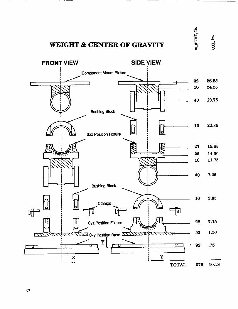
WEIGHT & CENTER OF GRAVITY
I
FRONT VIEW SIDE VIEW!
II! Component Mount Fixture
I
, Bushing Block
xz Position Rxture
Bushing Block
Clamps
ii
32 26.25
10 24.25
40 19.75
10 22.35
27 19.65
25 14.00
10 11.75
40 7.25
10 9.85
28 7.15
52 1.50
"t-'- 92 .75
I
TOTAL 376 10.18
32

oo=
yoo 0
0 o¢9 i_ /
o _* _ _/
o o
oOo _0 I-
0 rJ_ I__
o
I I I
J
"NI 'NOI.I.VJ.S
?,oo
oo
o° ,,,ooqp,,
OO
-!
- ¢,....
33

34
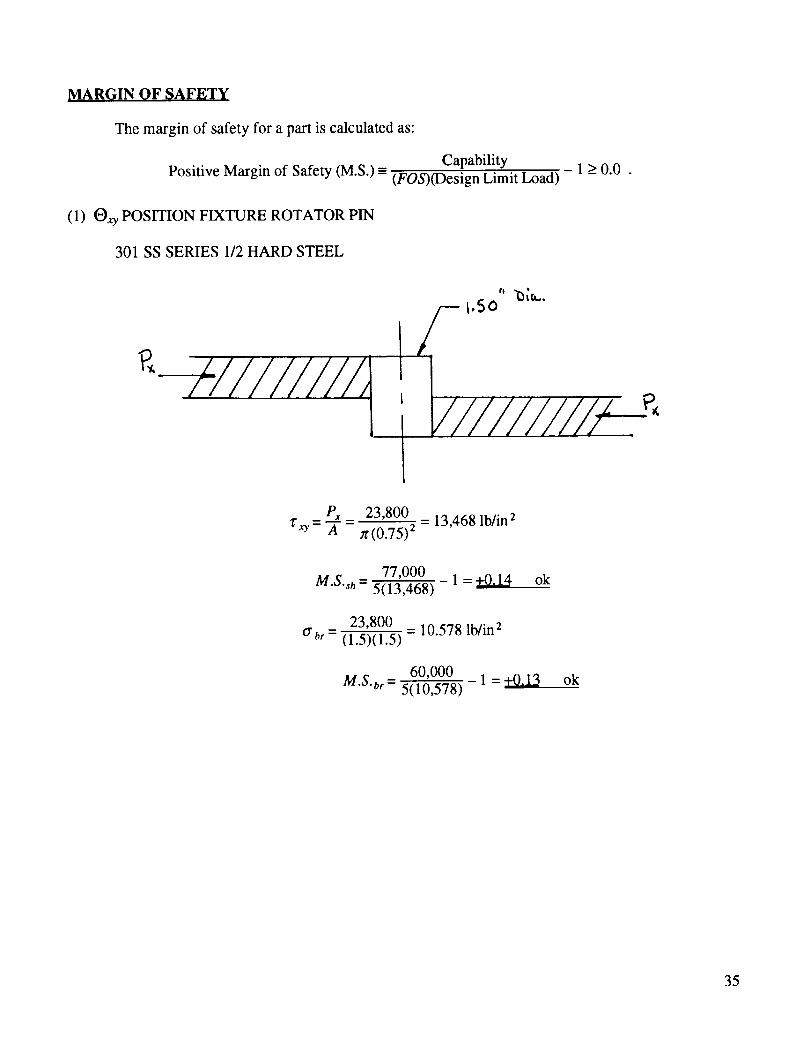
MARGIN OF SAFETY
The margin of safety for a part is calculated as:
CapabilityPositive Margin of Safety (M.S.) - (FOS)(Design Limit Load)
(1) Qxy POSITION FIXTURE ROTATOR PIN
301 SS SERIES 1/2 HARD STEEL
-1_0.0.
I1
" "O[a..
/--- l,So
_
Px 23,800 _ 13,468 lb/in 2z_y = A - n.(0.75) 2
77,000 1 = +9114M'S'sh- 5(13,468)
23,800 = 10.578 lb/in 2Crbr- (1.5)(1.5)
60,000 1 = +0.13M'S'br- 5(10,578)
ok
ok
35

(2) OxyCLAMPS (6)
301SSSERIES1/2HARD STEEL
30
P" = 4(9.75)(cos 30 °)
351,385
4(9.75)(0.866)= 10,404 lb.
Fasteners NAS 1958 1/2-inch-20 A286
Vsh = 21,200 lb Ptu = 30,900 lb
At = 0.171 in 2 Ash = O. 196 in 2
Fly = 150 ksi Fry = 180 ksi
PPext = -" = 5,202 lb2
Pbolt = PLDmax + (FOS)(n(_ )Pext
36

k b (3x10⁷)(0.196) = 3.36x10⁶ lb/in(P-kb+k a ; kb= 1.75
(lx107)(0"51-0"25':')_ = 17.671x10⁶ lb/inkl = 1.0
(lx107)(1) = 6.67x10⁶k2 - 1.5
(3x10⁷)(1) = 2.0x10⁶ lb/ink3 = 1.5
k - k2+k3 = 4.33x10⁶ lb/in2
k_"l
l,
/7r7
1 1 + 1 . ka.,,,g 3.48xlO61b/in- 4.33x10⁶ 17.67x10⁶ ' =
3.36 =0.49 ; 77 = 1/2- 3.36+3.48
P_lt u = 1.25(0.65)( 150,000)(0.171)+5(0.49)(0.5)(5,202)
= 20,840+6,372 = 27,121 lb
30,900 1=+0.13 okM.S.u,- 27,212
Pbott y = 20,840+3(0.49)(0.5)(5,202) = 24,664 lb
(0.171)(150,000) _ 1 = +Q,Q4 okM.S. yld = 24,664
Shear on clamp
1!0 1|
It
1,0
37

with Pext only
2(27,212) _ 18,141 lb/in 2_"- 3(1)
M.S.sh_ 77,000 1 = +_.2418,141
2(5,202)- 3,468 lb/in 2
77,000 1 = +_,44M'S'sh- 5(3,468)
ok
ok
Shear failure of AL Oxy plate with clamp insertsMS 21209 1/2-inch into 6061-T6
Ash > 7t_20)(1.25)(0.6)[1/40+...]
-1.18 in 2--_ I#
1,50
27,212
1.18= 23,0611b/m 2
25,000M'S'sh = 23,061 1 = +0.08 ok
(3) Oxy Position Fixture
-base plate 1.5 inch 6061-T6
M cos flp'=7rR 2
333,638
- _r(5.5)2
= 3,511 lb/in
3,511z" = = T.5 - 2,340 lb/in 2
25,000 1 = +1 1_M'S'sh - 5(2,340)
ok
'R5._
÷ I
f!
-/,.5 R
38

PJuter- 333,638 = 2,514 lb/inn'(6.5) 2
6M o 6(2,514) 6,704 lb/in 2crb=_= (1.5)2
38,000 1 = +0.13 okM.S.,- 5(6,704)
-base plate to support intersection
_. 60
Z.O
M - 333,638 _ 166,819 in-lb2
c = 5.5 in
I- 2"5(11)3 277.3in 412
K t = 2.0
(166'819)(5"5)2 = 6,617 lb/in 2orb = 277.3
38,000 1 = +Q_14M'S'b- 5(6,617)
ok
39

-Shear Bars
Oy z support
16,600 _ 2,767 lb/in 22(3)
25,000 = +0.80M.S.sh- 5(2,767)
r
l,
41
\ /
ok
|
4O

-Fastener NAS 1958 112 in A286
gul t "- 21,200 lb
Pult = 30,900 lb
At = 0.171 in 2
Pb = PLDmax+(FOS)(nO )Pext
FTU = 180 ksi
FTY = 150 ksi
Ash = 0.196 in 2
PLOma x = 1.25(0.65)(150,000)(0.171) = 20,840 lb
(3×10⁷)(0"196) = 1.176×10⁶ lb/inkb- 5
(3× 10⁷)(0.432-0.2812) Jr = 3.328×10⁶ lb/inka = 3
16,6001.176 =0.26 " 17= 1 . Pext-
= 1.176+3.328 ' 2 ' 4= 4,150 lb
Pb, = 20,240+(5)(0.26)(0.5)(4,150) = 23,538 lb
M.S., = +0.31 ok
/:'by= 20,840+(3)(0.26)(0.5)(4,150) = 22,458 lb
M.S.y = +Q. 14 ok
-Gear teeth
M - 225,448 _ 112,724 in-lb2
N = 36 teeth
r = 3.00 in (min)
41

Mt = 112,72436 = 3,131 in-lb/tooth
3,131 = 1,044 lb/toothF,=-- 3-
(1,044) = 1,600 lb/in 2_'b = 2.5(0.261)
25,000 1 = +2.12 okM.S.sh - 5(1,600)
O" b -- (1,044)(0.13)(0.1305) = 4,782 lb/in 22.5(0.261)3/12
38,000 _ 1 = +0.58 okM'S'b = 5(4,782)
(4) Bushing Block
M = 112,724 in-lb
M
Pext = 4(--_.5) - 3,315 lb/bolt
-Fastener NAS 1352-8 1/2 In alloy steel
Ptu = 24,100 lb.
At= 0.160 in 2
FTU = 150 ksi
PLDma x = 1.25(0.65)(105,000)(0.16) = 13,650 lb
3x10⁷(0.196) = 7.84x10⁶ lb/inkb = 0.75
lx107(0.752_0.2812)_k,, - 0.75
= 20.24)<106 lb/in
7.84 = 0.28= 7.84+20.24
42
/
/ L_"'_] i¢
425
2 8,lr
Ply = 16,870 lb.Ash = 0.196 in 2
FTY = 105 ksi
/
/
J
QFP
/,
.'15
tl
.'15
)

Pb,, = 13,650+5(0.5)(0.28)(3,315)= 15,970 lb
24,100 1=+0.50 okM.S.,,- 15,970
Pby = 13,650+3(0.5)(0.28)(3,315) = 15,042 lb
M.S. 16,870 1 =+Q,12 ok- 15,042
Oyz shear out
inserts MS21209 1[2 in D = 0.592 in
Ash = _r(13)(1.25)(0.592)[2_13)+...] = 1.16 in 2
15,970 13,767 lb/in 2z= 1.1-----C =
M.S.sh = 25,00013,767 1 =+0.81 ok
Oxz body
M = 225,448 in-lb
--_ 0¢
tr = (225,448)(2.75) = 7,453 1b/in 26(5.5) 3/12
M.S. = 38,000 1 = +0.02 ok5(7,453)
®xz bushing block and component mount fixture have positive margins of safety by similarityand because of lower loads at these stations.
43

APPROVAL
ROOT-SUM-SQUARE STRUCTURAL STRENGTH VERIFICATION APPROACH
By Henry M. Lee
The information in this report has been reviewed for technical content. Review of any informa-
tion concerning Department of Defense or nuclear energy activities or programs has been made by theMSFC Security Classification Officer. This report, in its entirety, has been determined to be unclassified.
J.C. BLAIR
Director, Structures and Dynamics Laboratory
'I_'US. GOVERNMENTPRINTING OFFICE 1994--533-108,O0062
44


![Empretec Newsletter 36 (UNCTAD-DIAE-ED-INF-2019-2)...wal\mUai a_ A _Nw vNlmVa_ aS ^ilNpNJ a]a^IVA 4# 3 lNTVa_A] JaqlmN a_ Ny mmqNm a_ pUN _pNl_ApVa_A] Ja_a^VJ TN_LA wVpUV_ pUN SlA^Nwal\](https://img.pdfslide.us/doc/110x75/5f72234e4e4c940af531d041/empretec-newsletter-36-unctad-diae-ed-inf-2019-2-walmuai-a-a-nw-vnlmva.jpg)


![Information folder [CTRL] A_(digital version)](https://img.pdfslide.us/doc/110x75/58a02db81a28ab4e768b6b79/information-folder-ctrl-adigital-version.jpg)

![BusinessLaw_Thesis_MPE A_ ROll NO 50[1]](https://img.pdfslide.us/doc/110x75/577d35591a28ab3a6b90353b/businesslawthesismpe-a-roll-no-501.jpg)
![Faster than a_-_lesson_slides[1]](https://img.pdfslide.us/doc/110x75/555a17bcd8b42a7d498b50dd/faster-than-a-lessonslides1.jpg)