Embed Size (px)
Citation preview
| NODIS Library | Program Formulation(7000s) | Search |
NASA
Procedural
Requirements
NPR 7123.1A Effective Date: March 26, 2007
Expiration Date: March 26, 2012
COMPLIANCE IS MANDATORY
NASA Systems Engineering Processes and Requirements
Responsible Office: Office of the Chief Engineer
Table of Contents
Preface
P.1 Purpose P.2 Applicability and Scope P.3 Authority P.4 References P.5 Measurement/Verification P.6 Cancellation
Prologue
Chapter 1. Introduction
1.1 Background 1.2 Framework for Systems Engineering Procedural Requirements 1.3 Systems Engineering Management Plan 1.4 Document Organization
Chapter 2. Institutional and Programmatic Requirements
2.1 Roles and Responsibilities 2.2 Implementation Architecture 2.3 Designated Governing Authority
Chapter 3. Requirements for Common Technical Processes
3.1 Introduction 3.2 Process Requirements
Chapter 4. NASA Oversight Activities on Contracted Projects
4.1 Introduction 4.2 Activities Prior to Contract Award 4.3 During Contract Performance 4.4 Contract Completion
Chapter 5. Systems Engineering Technical Reviews
5.1 Life Cycle 5.2 Technical Review Requirements 5.3 Minimum Required Set of Technical Reviews
Chapter 6. Systems Engineering Management Plan
6.1 Systems Engineering Management Plan Function 6.2 Roles and Responsibilities
Appendix A. Definitions
Appendix B. Acronyms
Appendix C. Practices for Common Technical Processes
C.1 System Design Processes
C.2 Product Realization Processes
C.3 Technical Management Processes
Appendix D. Systems Engineering Management Plan
D.1 Purpose and Use D.2 Terms Used D.3 SEMP Preparation D.4 SEMP Annotated Outline
Appendix E. Hierarchy of Related NASA Documents
Appendix F. Tailoring
NPR 7123.1A -- TOCVerify Current version before use at:
http://nodis3.gsfc.nasa.gov/Page 1 of 97
NPR 7123.1A -- TOCVerify Current version before use at:
http://nodis3.gsfc.nasa.gov/Page 1 of 97
Appendix G. Technical Review Entrance and Success Criteria
G.1 Program/System Requirements Review G.2 Program Approval Review G.3 Mission Concept Review G.4 System Requirements Review G.5 Mission Definition Review G.6 System Definition Review G.7 Preliminary Design Review G.8 Critical Design Review G.9 Production Readiness Review G.10 System Integration Review G.11 Test Readiness Review G.12 System Acceptance Review G.13 Operational Readiness Review G.14 Flight Readiness Review G.15 Post-Launch Assessment Review G.16 Critical Event Readiness Review G.17 Post-Flight Assessment Review G.18 Decommissioning Review G.19 Periodic Technical Review G.20 Technical Peer Reviews
Appendix H. Templates
H-1 Sample SE NPR Implementation Plan Template H-2 SE NPR Center Survey
Appendix I. Additional Reading
Table of Figures
Figure 1-1 - SE Framework Figure 2-1 - Implementation Architecture Figure 3-1 - SE Engine Figure 3-2 - Application of SE Engine Processes within System Structure Figure 5-1 - The NASA Program Life Cycle Figure 5-2 - The NASA Project Life Cycle Figure 5-3 - Product Line Technical Review Schedule Figure A-1 - Product-Based WBS Model Example Figure C-1 - Stakeholder Expectation Definition Process Figure C-2 - Technical Requirements Definition Process Figure C-3 - Logical Decomposition Process Figure C-4 - Design Solution Definition Process Figure C-5 -Sequencing of Product Realization Processes Figure C-6 - Product Implementation Process Figure C-7 - Product Integration Process Figure C-8 - Product Verification Process Figure C-9 - Product Validation Process Figure C-10 - Product Transition Process Figure C-11 - Technical Planning Process Figure C-12 - Requirements Management Process Figure C-13 - Interface Management Process Figure C-14 - Technical Risk Management Process Figure C-15 - Configuration Management Process Figure C-16 - Technical Data Management Process Figure C-17 - Technical Assessment Process Figure C-18 - Decision Analysis Process
Table of Tables
Table G-1 - P/SRR Entrance and Success Criteria Table G-2 - PAR Entrance and Success Criteria Table G-3 - MCR Entrance and Success Criteria Table G-4 - SRR Entrance and Success Criteria Table G-5 - MDR Entrance and Success Criteria Table G-6 - SDR Entrance and Success Criteria Table G-7 - PDR Entrance and Success Criteria Table G-8 - CDR Entrance and Success Criteria Table G-9 - PRR Entrance and Success Criteria Table G-10 - SIR Entrance and Success Criteria Table G-11 - TRR Entrance and Success Criteria Table G-12 - SAR Entrance and Success Criteria Table G-13 - ORR Entrance and Success Criteria Table G-14 - FRR Entrance and Success Criteria Table G-15 - PLAR Entrance and Success Criteria Table G-16 - CERR Entrance and Success Criteria Table G-17 - PFAR Entrance and Success Criteria Table G-18 - DR Entrance and Success Criteria Table G-19 - Technology Readiness Levels
NPR 7123.1A -- TOCVerify Current version before use at:
http://nodis3.gsfc.nasa.gov/Page 2 of 97
NPR 7123.1A -- TOCVerify Current version before use at:
http://nodis3.gsfc.nasa.gov/Page 2 of 97
Preface
P.1 Purpose
The purpose of this document is to clearly articulate and establish the requirements on the implementing organization for performing, supporting, and evaluating systems engineering.Systems engineering is a logical systems approach performed by multidisciplinary teams to engineer and integrate NASA?s systems to ensure NASA products meet customers? needs.Implementation of this systems approach will enhance NASA?s core engineering, management, and scientific capabilities and processes to ensure safety and mission success, increaseperformance, and reduce cost. This systems approach is applied to all elements of a system and all hierarchical levels of a system over the complete project life cycle.
P.2 Applicability and Scope
a. This NASA Procedural Requirement (NPR) applies to NASA Headquarters and NASA Centers, including component facilities and technical and service support centers. It also appliesto the Jet Propulsion Laboratory to the extent specified in its contracts with NASA. This NPR applies to NASA employees and their service contractors that use NASA processes toaugment and support NASA technical work. NASA NPRs and this Systems Engineering NPR (SE NPR) do not apply to NASA contracts except as the NASA technical team flows downthe systems engineering responsibilities to all members of the system team, including contractors and subcontractors. (See Chapter 4.)
b. The scope of this document encompasses the common technical processes for large and small projects and activities in flight systems and ground support (FS&GS) projects, advancedtechnology development (ATD) projects with deliverables to FS&GS projects, information systems and technology projects, and institutional projects (IP). Application of this NPR toConstruction of Facilities (CoF) and Environmental Compliance and Restoration (ECR) projects (or portions thereof) should be scaled in accordance with the level of systems engineeringfor the function of the structure and documented in the systems engineering management plan (SEMP) (as required). In this sense, the design of facilities (or parts of facilities) forprocessing FS&GS activities would require appropriate application of systems engineering effort, ensuring that interfaces with and functional requirements of the FS&GS systemsengineering are addressed. The design of administrative facilities or soil remediation projects may not require the application of specific systems engineering efforts. Engineeringrequirements for CoF and ECR projects are specified in NPR 8820.2 and NPR 8590.1, respectively. Applying the common technical processes and reviews may also benefit basic andapplied research (BAR) and other ATD projects. They are recommended but not required for BAR and ATD projects.
c. In this document, the word ?project? generally refers to a unit of work performed in programs, projects, and activities. Management of a work unit is referred to as ?project management,?which includes managing programs, projects, and activities. A project is : (1) A specific investment having defined goals, objectives, requirements, life-cycle cost, a beginning, and an end.A project yields new or revised products or services that directly address NASA?s strategic needs. Projects may be performed wholly in-house; by Government, industry, academiapartnerships; or through contracts with private industry. (2) A unit of work performed in programs, projects, and activities. Requirements for technical work on projects, therefore, alsoapply to technical work performed on programs.
d. The requirements enumerated in this document are applicable to all new programs and projects, as well as to all programs and projects currently in Formulation phase as of the effectivedate of this document. (See NPR 7120.5 for definitions of program phases.) This NPR also applies to programs and projects in their Implementation phase as of the effective date of thisdocument. However, the technical team may request permission from the designated governing authority to be allowed to continue without complying with all or sections of this NPR.
e. Many other discipline areas such as safety, medical, reliability, maintainability, quality assurance, information technology, security, logistics, environmental, etc., perform functionsduring project life-cycle phases that influence or are influenced by the engineering functions performed and need to be fully integrated with the engineering functions. The description ofthese disciplines and their relationship to the overall management life cycle are defined in other NASA directives; for example, the safety, medical, reliability, maintainability, and qualityassurance requirements are defined in the 8700 series of directives.
P.3 Authority
a. 42 U.S.C. 2473(c)(1), Section 203(c)(1), National Aeronautics and Space Act of 1958, as amended.
b. NPD 1000.0, Strategic Management & Governance Handbook.
c. NPD 1001.0, 2006 NASA Strategic Plan
d. NPD 1000.3, The NASA Organization.
e. NPD 7120.4, Program/Project Management.
P.4 References
a. The NPD 8700, NASA Safety and Mission Assurance (S&MA) and Success policy series.
b. NPR 7120.5, NASA Space Flight Program and Project Management Requirements.
c. NPD 2820.1, NASA Software Policy.
d. NPR 7150.2, NASA Software Engineering Requirements.
e. NPR 8000.4, Risk Management Procedural Requirements.
f. SP-6105, NASA Systems Engineering Handbook.
g. NPD 1080.1 NASA Science Policy.
h. NPR 1080.1 NASA Science Management.
i. NPR 8820.2 Facility Project Implementation Guide.
j. NPD 1440.6, NASA Records Management.
k. NPR 1441.1, NASA Records Retention Schedules.
l. NPR 1800.1, NASA Occupational Health Program Procedures.
P.5 Measurement/Verification
Compliance with this NPR will be documented by Center Directors in the SE NPR Implementation Plan, which reports how the particular Center will assess compliance to the SE NPR. Inaddition, the Office of the Chief Engineer (OCE) conducts periodic assessments at the Centers to obtain feedback on the effectiveness of the SE NPR to facilitate updating the NPR.
P.6 Cancellation
NPR 7123.1A -- PrefaceVerify Current version before use at:
http://nodis3.gsfc.nasa.gov/Page 3 of 97
NPR 7123.1A -- PrefaceVerify Current version befor use at:
http://nodis3.gsfc.nasa.gov/Page 3 of 97
NPR 7123.1, NASA Systems Engineering Processes and Requirements, dated March 13, 2006, is cancelled on the effective date of NPR 7123.1A.
/S/
Christopher J. Scolese
Chief Engineer
DISTRIBUTION:
NODIS
NPR 7123.1A -- PrefaceVerify Current version before use at:
http://nodis3.gsfc.nasa.gov/Page 4 of 97
NPR 7123.1A -- PrefaceVerify Current version befor use at:
http://nodis3.gsfc.nasa.gov/Page 4 of 97
STUFF
NPR 7123.1A -- PrologueVerify Current version before use at:
http://nodis3.gsfc.nasa.gov/Page 5 of 97
NPR 7123.1A -- PrologueVerify Current version befor use at:
http://nodis3.gsfc.nasa.gov/Page 5 of 97
Chapter 1. Introduction
1.1 Background
1.1.1
Systems engineering at NASA requires the application of a systematic, disciplined engineering approach that is quantifiable, recursive, iterative, and repeatable for the development,operation, maintenance, and disposal of systems integrated into a whole throughout the life cycle of a project or program. The emphasis of systems engineering is on safely achievingstakeholder functional, physical, and operational performance requirements in the intended use environments over the system?s planned life within cost and schedule constraints.
1.1.2
This NPR establishes a core set of common Agency-level technical processes and requirements needed to define, develop, realize, and integrate the quality of the system products createdand acquired by or for NASA. The processes described in this document build upon and apply best practices and lessons learned from NASA, other governmental agencies, and industry toclearly delineate a successful model to complete comprehensive technical work, reduce program and technical risk, and improve mission success. The set of common processes in this NPRmay be supplemented and tailored to achieve specific project requirements. (See Appendix F. Tailoring.)
1.1.3
Under the lean governance of the updated NPD 1000.0, the relationship of the program/project management and the technical team was clarified to reflect new technical authority. Theprogram/project manager (PM) has overall responsibility for their program/project. The technical team works with and for the PM to accomplish the goals of the project. Due to thisupdated governance, there is a need to clearly define the role of the systems engineering management plan (SEMP) and how it will be developed. The technical team, working under theoverall program management plan (PMP), develops and updates the SEMP as necessary. The technical team works with the PM to review the content and obtain concurrence. This allowsfor thorough discussion and coordination of how the proposed technical activities would impact the programmatic, cost, and schedule aspects of the project. However, in cases of puretechnical issues and for approval of requested waivers to technical requirements, the technical team also has an independent route through the technical designated governing authority(DGA) (as described in Section 2.3) to resolve issues with program/project management. Once all issues are resolved, the PM signs the SEMP. It then goes to the DGA for final signature.The DGA signature assures that an independent review has evaluated the technical aspects of the technical plans and allows for approval of technical waivers or tailoring of therequirements of this NPR and other relevant technical standards that pertain to this NPR.
1.1.4 Precedence
The order of precedence in case of conflict between requirements is 42 U.S.C. 2473(c)(1), Section 203(c)(1), National Aeronautics and Space Act of 1958, as amended; NPD 1000.0,Strategic Management & Governance Handbook; NPD 1000.3, The NASA Organization; NPD 7120.4, Program/Project Management; and NPR 7123.1, NASA Systems EngineeringProcesses and Requirements.
1.1.5 Requirement Verbs
In this NPR, a requirement is identified by "shall," a good practice by "should," permission by "may" or "can," expected outcome or action by "will," and descriptive material by "is" or"are" (or another verb form of "to be").
1.1.6 Figures
Figures within this NPR are not intended to be prescriptive but notional.
1.2 Framework for Systems Engineering Procedural Requirements
There are three major groupings of requirements within the Office of the Chief Engineer (OCE), i.e., program management requirements, systems engineering requirements, andindependent review. This NPR focuses on the systems engineering requirements. (See Appendix E for the hierarchy of related documents.)
1.2.1 Systems Engineering Framework
1.2.1.1
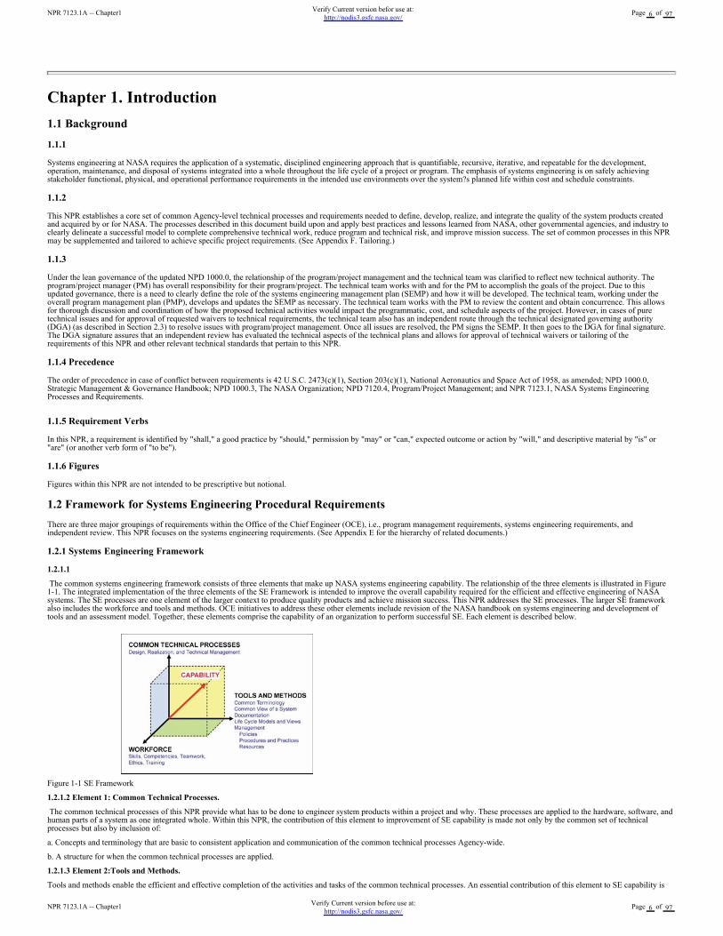
The common systems engineering framework consists of three elements that make up NASA systems engineering capability. The relationship of the three elements is illustrated in Figure1-1. The integrated implementation of the three elements of the SE Framework is intended to improve the overall capability required for the efficient and effective engineering of NASAsystems. The SE processes are one element of the larger context to produce quality products and achieve mission success. This NPR addresses the SE processes. The larger SE frameworkalso includes the workforce and tools and methods. OCE initiatives to address these other elements include revision of the NASA handbook on systems engineering and development oftools and an assessment model. Together, these elements comprise the capability of an organization to perform successful SE. Each element is described below.
Figure 1-1 SE Framework
1.2.1.2 Element 1: Common Technical Processes.
The common technical processes of this NPR provide what has to be done to engineer system products within a project and why. These processes are applied to the hardware, software, andhuman parts of a system as one integrated whole. Within this NPR, the contribution of this element to improvement of SE capability is made not only by the common set of technicalprocesses but also by inclusion of:
a. Concepts and terminology that are basic to consistent application and communication of the common technical processes Agency-wide.
b. A structure for when the common technical processes are applied.
1.2.1.3 Element 2:Tools and Methods.
Tools and methods enable the efficient and effective completion of the activities and tasks of the common technical processes. An essential contribution of this element to SE capability is
NPR 7123.1A -- Chapter1Verify Current version before use at:
http://nodis3.gsfc.nasa.gov/Page 6 of 97
NPR 7123.1A -- Chapter1Verify Current version befor use at:
http://nodis3.gsfc.nasa.gov/Page 6 of 97
the improvement of the engineering infrastructure through the three Agency-wide initiatives listed below.
a. Infusion of advanced methods and tools in the SE processes to achieve greater efficiency, collaboration, and communication among distributed teams.
b. Preparation of a NASA handbook on SE methodologies intended to provide a source for various methods and procedures that Centers can draw upon to plan implementation of therequired processes in their projects. This will be an update of the current NASA Systems Engineering Handbook (SP-6105) that will be aligned with NPR 7120.5 and the SE NPR.
c. Creation or adoption of an assessment model to measure the SE capability of projects within NASA and to assess the improvements of capability resulting from implementation of the SENPR, use of adopted methods and tools, and workforce engineering training.
1.2.1.4 Element 3:Workforce.
A well-trained, knowledgeable, and experienced technical workforce is essential for improving SE capability. The workforce must be able to apply NASA and Center standardized methodsand tools for the completion of the required SE processes within the context of the program or project to which they are assigned. In addition, they must be able to effectively communicaterequirements and solutions to customers, other engineers, and management to work efficiently and effectively on a team. Issues of recruitment, retention, and training are aspects includedin this element. The OCE will facilitate the training of the NASA workforce on the application of this and associated NPRs.
1.2.1.5 SE Capability.
Together, the three elements of Figure 1-1 comprise an Agency-wide capability to perform successful SE in the engineering of NASA system products.
1.3 Systems Engineering Management Plan
A Systems Engineering Management Plan (SEMP) is used to establish the technical content of the engineering work early in the Formulation phase for each project and updated throughoutthe project life cycle. The SEMP provides the specifics of the technical effort and describes what technical processes will be used, how the processes will be applied using appropriateactivities, how the project will be organized to accomplish the activities, and the cost and schedule associated with accomplishing the activities. The process activities are driven by thecritical or key events during any phase of a life cycle (including operations) that set the objectives and work product outputs of the processes and how the processes are integrated. (SeeChapter 6 for a description of the SEMP and Appendix D for an annotated outline for the SEMP.) The SEMP provides the communication bridge between the project management team andthe technical implementation teams and within technical teams. The SEMP provides the framework to realize the appropriate work products that meet the entry and exit criteria of theapplicable project life-cycle phases and provides management with necessary information for making decisions.
1.4 Document Organization
This SE NPR is organized into the following chapters.
a. The Preface describes items such as the applicability, scope, authority, and references of this SE NPR.
b. The Prologue describes the purpose and vision for this SE NPR.
c. Chapter 1 describes the SE framework and introduces the SEMP.
d. Chapter 2 describes the institutional and programmatic requirements, including roles and responsibilities.
e. Chapter 3 describes the core set of common Agency-level technical processes and requirements for engineering NASA system products throughout the product life cycle. Appendix Ccontains supplemental amplifying material.
f. Chapter 4 describes the activities and requirements to be accomplished by assigned NASA technical teams or individuals (NASA employees and their service support contractors) whenperforming technical oversight of a prime or external contractor.
g. Chapter 5 describes the technical review requirements throughout the program and project life cycles.
h. Chapter 6 describes the SEMP, including the SEMP role, functions, and content. Appendix D provides details of a generic SEMP annotated outline.
NPR 7123.1A -- Chapter1Verify Current version before use at:
http://nodis3.gsfc.nasa.gov/Page 7 of 97
NPR 7123.1A -- Chapter1Verify Current version befor use at:
http://nodis3.gsfc.nasa.gov/Page 7 of 97
Chapter 2. Institutional and Programmatic Requirements
2.1 Roles and Responsibilities
2.1.1 General
2.1.1.1
The roles and responsibilities of senior management are defined in part in NPD 1000.0, Strategic Management & Governance Handbook. NPR 7120.5, NASA Space Flight Program andProject Management Requirements; NPD 7120.4, Program/Project Management; and other NASA directives define the responsibilities of program and project managers. This NPRestablishes systems engineering processes and responsibilities.
2.1.1.2
The OCE, under the authority of this SE NPR, shall ensure compliance with this SE NPR.
2.1.1.3
For programs and projects involving more than one Center, the lead organization shall develop documentation to describe the hierarchy and reconciliation of Center plans implementing thisNPR. The governing mission directorate determines whether a Center executes a project in a lead role or in a peer role. For Centers in peer roles, compliance should be jointly negotiated.
2.1.1.4
For systems that contain software, the technical team shall ensure that software developed within NASA or acquired complies with NPD 2820.1, NASA Software Policy, and NPR 7150.2,NASA Software Engineering Requirements. Note that NPR 7150.2 elaborates on the requirements in this document and determines the applicability of requirements based on the Agency'ssoftware classification. Also note that NPR 7150.2 contains additional Agency requirements for the acquisition, development, maintenance, and management of software.
2.1.1.5
The OCE shall be the clearinghouse for systems engineering policies to ensure compatibility across NASA. In the event of differences between program or project offices and the OCEstaff, the conflict will ultimately reach the NASA Chief Engineer or mission director level. If agreement is not achieved at this level, the conflict will be brought to the NASA Administratorfor resolution.
2.1.1.6
In this document, the phrase "the Center Directors shall..." means the roles and responsibilities of the Center Directors may be further delegated within the organization as appropriate to thescope and scale of the system.
2.1.2 Center Directors
2.1.2.1
Center Directors oversee and manage the infrastructure for the successful execution of technical authority, support, and assurance of all programs and projects.
2.1.2.2
Center Directors shall perform the following activities or delegate them to the appropriate Center organization:
a. Develop the SE NPR Implementation Plan per the template in Appendix H-1 describing how the requirements of this SE NPR will be applied to the programs and projects under theircognizance or authority.
b. Establish policies, procedures, and processes to execute the requirements of this SE NPR.
c. Assess and take corrective actions to improve the execution of the requirements of this SE NPR.
d. Perform the SE NPR Center Survey in accordance with Appendix H-2 for the purpose of providing feedback on the SE NPR. The initial Center Survey will be submitted five months fromthe effective date of this SE NPR. Subsequent updates will be upon the request of the OCE, no earlier than nine months after the initial submission. The Center Survey will use the commonsurvey tool in Appendix H-2 and will be submitted through the Center System Engineering Working Group (SEWG) representative.
e. Select appropriate standards applicable to projects under their control.
2.1.3 Technical Teams
Each technical team shall execute the Center processes intended to implement this SE NPR under the oversight of the Center Directors in accordance with the SEMP. The makeup andorganization of each technical team is the responsibility of each Center or program and includes the personnel required to implement the project.
2.2 Implementation Architecture
2.2.1 Implementation Plan
2.2.1.1
Figure 2-1 illustrates the engineering implementation flow and key documents. NPD 7120.4 establishes the policy for engineering and program and project management for the Agency.From that directive, the OCE developed and published this SE NPR, which is consistent and complementary to NPR 7120.5 and other pertinent Agency directives. The requirementsestablished in this SE NPR will flow down to the implementing organizations and Centers.
2.2.1.2
The Center Directors shall submit their SE NPR Implementation Plan to the OCE within three months after the effective date of this NPR. The plan will be updated as required. The SENPR Implementation Plan will be provided to mission directorates for review and comment. Each SE NPR Implementation Plan will be approved by the OCE and include the applicabledocuments employed by the individual Centers. These Center documents may include Center procedural requirements, work instructions, standards, and rules, as well as other Center-uniquedocumentation. The SE NPR is a requirements document that specifies what needs to be accomplished at an Agency level. There will also be a body of knowledge developed to assist in theimplementation of the NPR. This body of knowledge will include an updated NASA Systems Engineering Handbook (SP-6105) as well as best practices, standards, and templates.
2.2.1.3
The Center Directors shall develop and document in the SE NPR Implementation Plan how the particular Center will assess compliance to the SE NPR and provide regular updates to theOCE. In addition, the OCE will conduct periodic updates at the Centers to obtain feedback on the effectiveness of the SE NPR to facilitate updating the NPR.
NPR 7123.1A -- Chapter2Verify Current version before use at:
http://nodis3.gsfc.nasa.gov/Page 8 of 97
NPR 7123.1A -- Chapter2Verify Current version befor use at:
http://nodis3.gsfc.nasa.gov/Page 8 of 97
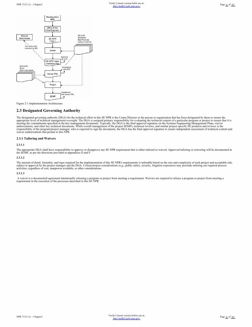
Figure 2-1 Implementation Architecture
2.3 Designated Governing Authority
The designated governing authority (DGA) for the technical effort in this SE NPR is the Center Director or the person or organization that has been designated by them to ensure theappropriate level of technical management oversight. The DGA is assigned primary responsibility for evaluating the technical content of a particular program or project to ensure that it ismeeting the commitments specified in the key management documents. Typically, the DGA is the final approval signature on the Systems Engineering Management Plans, waiverauthorizations, and other key technical documents. While overall management of the project SEMPs, technical reviews, and similar project-specific SE products and reviews is theresponsibility of the program/project manager, who is expected to sign the documents, the DGA has the final approval signature to ensure independent assessment of technical content andwaiver authorizations that pertain to this NPR.
2.3.1 Tailoring and Waivers
2.3.1.1
The appropriate DGA shall have responsibility to approve or disapprove any SE NPR requirement that is either tailored or waived. Approved tailoring or waivering will be documented inthe SEMP, as per the directions provided in appendices D and F.
2.3.1.2
The amount of detail, formality, and rigor required for the implementation of this SE NPR's requirements is tailorable based on the size and complexity of each project and acceptable risk,subject to approval by the project manager and the DGA. Critical project considerations (e.g., public safety, security, litigation exposures) may preclude tailoring out required processactivities, regardless of cost, manpower available, or other considerations.
2.3.1.3
A waiver is a documented agreement intentionally releasing a program or project from meeting a requirement. Waivers are required to release a program or project from meeting arequirement in the execution of the processes described in this SE NPR.
NPR 7123.1A -- Chapter2Verify Current version before use at:
http://nodis3.gsfc.nasa.gov/Page 9 of 97
NPR 7123.1A -- Chapter2Verify Current version befor use at:
http://nodis3.gsfc.nasa.gov/Page 9 of 97
Chapter 3. Requirements for Common Technical Processes
3.1 Introduction
3.1.1
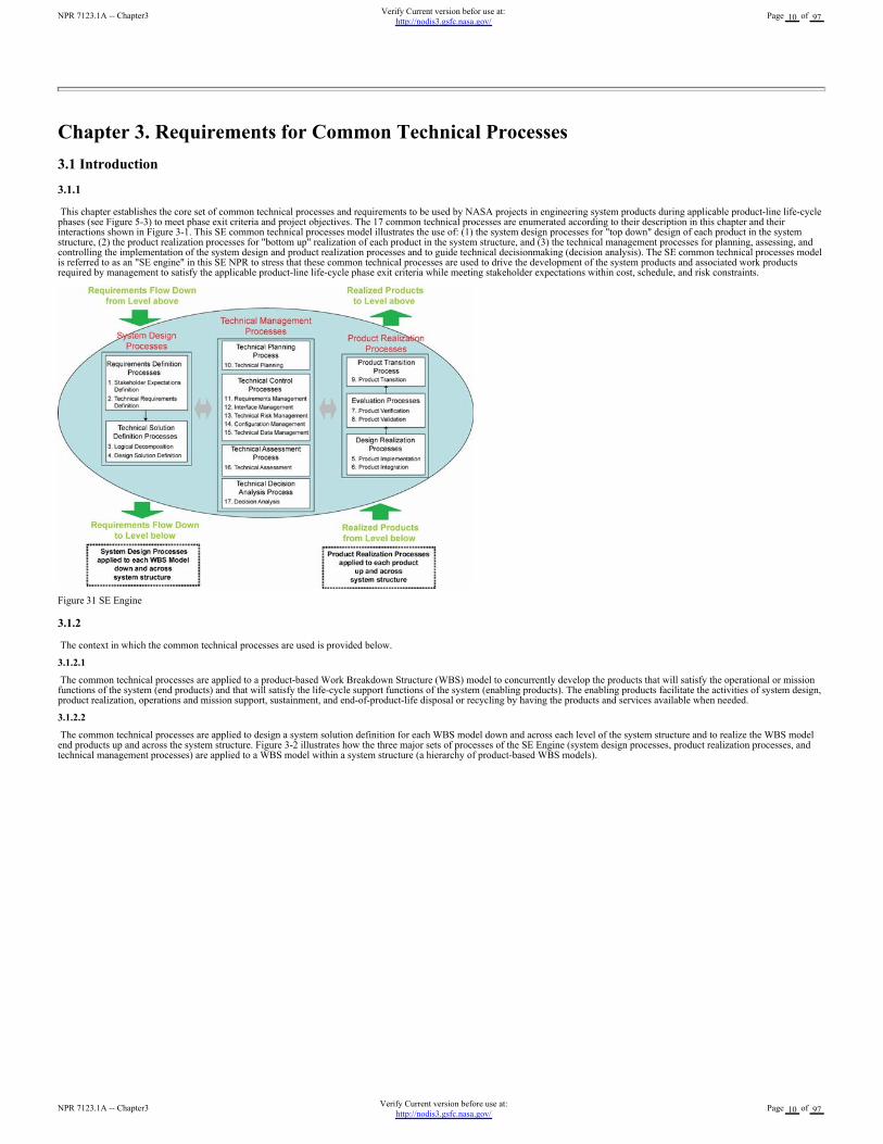
This chapter establishes the core set of common technical processes and requirements to be used by NASA projects in engineering system products during applicable product-line life-cyclephases (see Figure 5-3) to meet phase exit criteria and project objectives. The 17 common technical processes are enumerated according to their description in this chapter and theirinteractions shown in Figure 3-1. This SE common technical processes model illustrates the use of: (1) the system design processes for "top down" design of each product in the systemstructure, (2) the product realization processes for "bottom up" realization of each product in the system structure, and (3) the technical management processes for planning, assessing, andcontrolling the implementation of the system design and product realization processes and to guide technical decisionmaking (decision analysis). The SE common technical processes modelis referred to as an "SE engine" in this SE NPR to stress that these common technical processes are used to drive the development of the system products and associated work productsrequired by management to satisfy the applicable product-line life-cycle phase exit criteria while meeting stakeholder expectations within cost, schedule, and risk constraints.
Figure 31 SE Engine
3.1.2
The context in which the common technical processes are used is provided below.
3.1.2.1
The common technical processes are applied to a product-based Work Breakdown Structure (WBS) model to concurrently develop the products that will satisfy the operational or missionfunctions of the system (end products) and that will satisfy the life-cycle support functions of the system (enabling products). The enabling products facilitate the activities of system design,product realization, operations and mission support, sustainment, and end-of-product-life disposal or recycling by having the products and services available when needed.
3.1.2.2
The common technical processes are applied to design a system solution definition for each WBS model down and across each level of the system structure and to realize the WBS modelend products up and across the system structure. Figure 3-2 illustrates how the three major sets of processes of the SE Engine (system design processes, product realization processes, andtechnical management processes) are applied to a WBS model within a system structure (a hierarchy of product-based WBS models).
NPR 7123.1A -- Chapter3Verify Current version before use at:
http://nodis3.gsfc.nasa.gov/Page 10 of 97
NPR 7123.1A -- Chapter3Verify Current version befor use at:
http://nodis3.gsfc.nasa.gov/Page 10 of 97
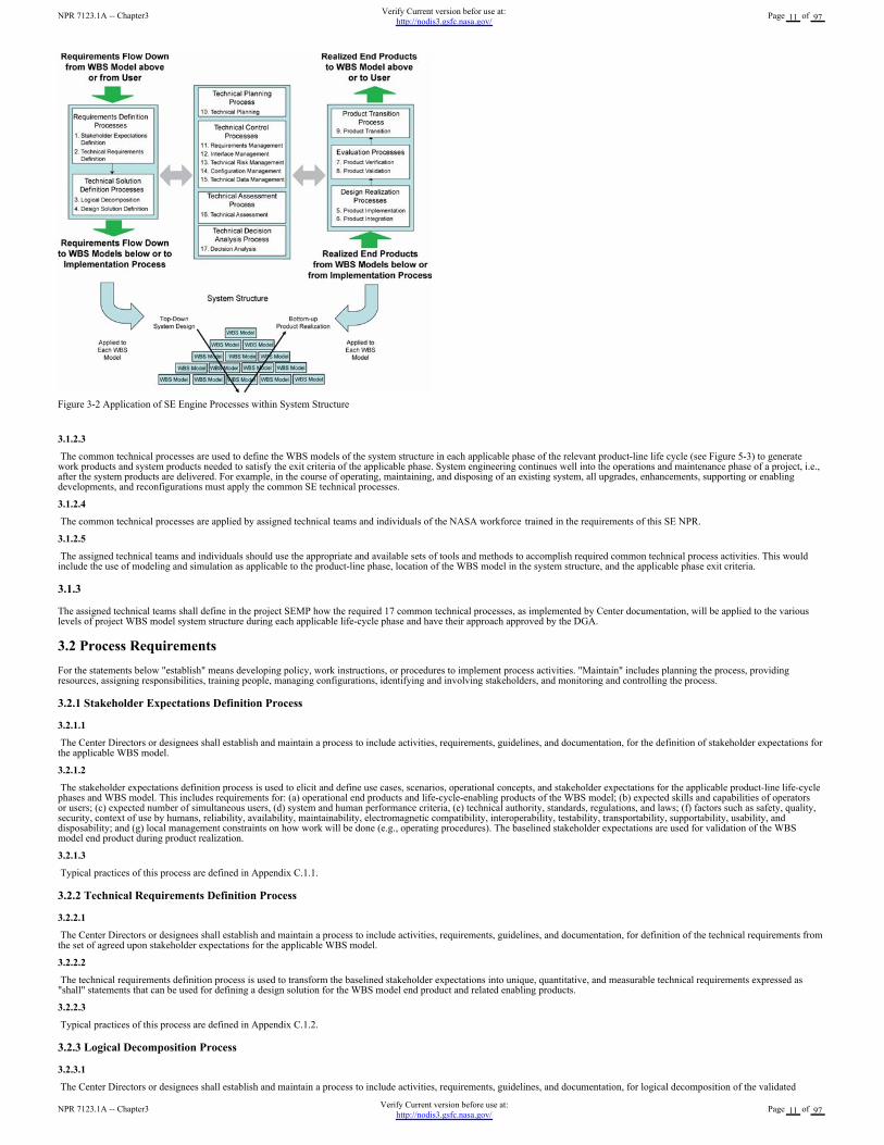
Figure 3-2 Application of SE Engine Processes within System Structure
3.1.2.3
The common technical processes are used to define the WBS models of the system structure in each applicable phase of the relevant product-line life cycle (see Figure 5-3) to generatework products and system products needed to satisfy the exit criteria of the applicable phase. System engineering continues well into the operations and maintenance phase of a project, i.e.,after the system products are delivered. For example, in the course of operating, maintaining, and disposing of an existing system, all upgrades, enhancements, supporting or enablingdevelopments, and reconfigurations must apply the common SE technical processes.
3.1.2.4
The common technical processes are applied by assigned technical teams and individuals of the NASA workforce trained in the requirements of this SE NPR.
3.1.2.5
The assigned technical teams and individuals should use the appropriate and available sets of tools and methods to accomplish required common technical process activities. This wouldinclude the use of modeling and simulation as applicable to the product-line phase, location of the WBS model in the system structure, and the applicable phase exit criteria.
3.1.3
The assigned technical teams shall define in the project SEMP how the required 17 common technical processes, as implemented by Center documentation, will be applied to the variouslevels of project WBS model system structure during each applicable life-cycle phase and have their approach approved by the DGA.
3.2 Process Requirements
For the statements below "establish" means developing policy, work instructions, or procedures to implement process activities. "Maintain" includes planning the process, providingresources, assigning responsibilities, training people, managing configurations, identifying and involving stakeholders, and monitoring and controlling the process.
3.2.1 Stakeholder Expectations Definition Process
3.2.1.1
The Center Directors or designees shall establish and maintain a process to include activities, requirements, guidelines, and documentation, for the definition of stakeholder expectations forthe applicable WBS model.
3.2.1.2
The stakeholder expectations definition process is used to elicit and define use cases, scenarios, operational concepts, and stakeholder expectations for the applicable product-line life-cyclephases and WBS model. This includes requirements for: (a) operational end products and life-cycle-enabling products of the WBS model; (b) expected skills and capabilities of operatorsor users; (c) expected number of simultaneous users, (d) system and human performance criteria, (e) technical authority, standards, regulations, and laws; (f) factors such as safety, quality,security, context of use by humans, reliability, availability, maintainability, electromagnetic compatibility, interoperability, testability, transportability, supportability, usability, anddisposability; and (g) local management constraints on how work will be done (e.g., operating procedures). The baselined stakeholder expectations are used for validation of the WBSmodel end product during product realization.
3.2.1.3
Typical practices of this process are defined in Appendix C.1.1.
3.2.2 Technical Requirements Definition Process
3.2.2.1
The Center Directors or designees shall establish and maintain a process to include activities, requirements, guidelines, and documentation, for definition of the technical requirements fromthe set of agreed upon stakeholder expectations for the applicable WBS model.
3.2.2.2
The technical requirements definition process is used to transform the baselined stakeholder expectations into unique, quantitative, and measurable technical requirements expressed as"shall" statements that can be used for defining a design solution for the WBS model end product and related enabling products.
3.2.2.3
Typical practices of this process are defined in Appendix C.1.2.
3.2.3 Logical Decomposition Process
3.2.3.1
The Center Directors or designees shall establish and maintain a process to include activities, requirements, guidelines, and documentation, for logical decomposition of the validated
NPR 7123.1A -- Chapter3Verify Current version before use at:
http://nodis3.gsfc.nasa.gov/Page 11 of 97
NPR 7123.1A -- Chapter3Verify Current version befor use at:
http://nodis3.gsfc.nasa.gov/Page 11 of 97
technical requirements of the applicable WBS model.
3.2.3.2
The logical decomposition process is used to improve understanding of the defined technical requirements and the relationships among the requirements (e.g., functional, behavioral, andtemporal) and to transform the defined set of technical requirements into a set of logical decomposition models and their associated set of derived technical requirements for input to thedesign solution definition process.
3.2.3.3
Typical practices of this process are defined in Appendix C.1.3.
3.2.4 Design Solution Definition Process
3.2.4.1
The Center Directors or designees shall establish and maintain a process to include activities, requirements, guidelines, and documentation, for designing product solution definitions withinthe applicable WBS model that satisfy the derived technical requirements.
3.2.4.2
The design solution definition process is used to translate the outputs of the logical decomposition process into a design solution definition that is in a form consistent with the product-linelife-cycle phase and WBS model location in the system structure and that will satisfy phase exit criteria. This includes transforming the defined logical decomposition models and theirassociated sets of derived technical requirements into alternative solutions, then analyzing each alternative to be able to select a preferred alternative, and fully defining that alternative into afinal design solution definition that will satisfy the technical requirements. These design solution definitions will be used for generating end products either by using the productimplementation process or product integration process as a function of the position of the WBS model in the system structure and whether there are additional subsystems of the end productthat need to be defined. The output definitions from the design solution (end product specifications) will be used for conducting product verification.
3.2.4.3
Typical practices of this process are defined in Appendix C.1.4.
3.2.5 Product Implementation Process
3.2.5.1
The Center Directors or designees shall establish and maintain a process to include activities, requirements, guidelines, and documentation, for implementation of a design solutiondefinition by making, buying, or reusing an end product of the applicable WBS model.
3.2.5.2
The product implementation process is used to generate a specified product of a WBS model through buying, making, or reusing in a form consistent with the product-line life-cycle phaseexit criteria and that satisfies the design solution definition specified requirements (e.g., drawings, specifications).
3.2.5.3
Typical practices of this process are defined in Appendix C.2.1
3.2.6 Product Integration Process
3.2.6.1
The Center Directors or designees shall establish and maintain a process to include activities, requirements, guidelines, and documentation for the integration of lower level products into anend product of the applicable WBS model in accordance with its design solution definition.
3.2.6.2
The product integration process is used to transform the design solution definition into the desired end product of the WBS model through assembly and integration of lower level, validatedend products in a form consistent with the product-line life-cycle phase exit criteria and that satisfies the design solution definition requirements (e.g., drawings, specifications).
3.2.6.3
Typical practices of this process are defined in Appendix C.2.2.
3.2.7 Product Verification Process
3.2.7.1
The Center Directors or designees shall establish and maintain a process to include activities, requirements, guidelines, and documentation, for verification of end products generated by theproduct implementation process or product integration process against their design solution definitions.
3.2.7.2
The product verification process is used to demonstrate that an end product generated from product implementation or product integration conforms to its design solution definitionrequirements as a function of the product-line life-cycle phase and the location of the WBS model end product in the system structure. Special attention is given to demonstrating satisfactionof the measures of performance (MOPs) defined for each measure of effectiveness (MOEs) during conduct of the technical requirements definition process.
3.2.7.3
Typical practices of this process are defined in Appendix C.2.3.
3.2.8 Product Validation Process
3.2.8.1
The Center Directors or designees shall establish and maintain a process to include activities, requirements, guidelines, and documentation, for validation of end products generated by theproduct implementation process or product integration process against their stakeholder expectations.
3.2.8.2
The product validation process is used to confirm that a verified end product generated by product implementation or product integration fulfills (satisfies) its intended use when placed inits intended environment and to ensure that any anomalies discovered during validation are appropriately resolved prior to delivery of the product (if validation is done by the supplier of theproduct) or prior to integration with other products into a higher-level assembled product (if validation is done by the receiver of the product). The validation is done against the set ofbaselined stakeholder expectations. Special attention should be given to demonstrating satisfaction of the MOEs identified during conduct of the stakeholder expectations definition process.The type of product validation is a function of the form of the product and product-line life-cycle phase and in accordance with an applicable customer agreement.
3.2.8.3
Typical practices of this process are defined in Appendix C.2.4.
3.2.9 Product Transition Process
3.2.9.1
The Center Directors or designees shall establish and maintain a process to include activities, requirements, guidelines, and documentation, for transitioning end products to the next higherlevel WBS-model customer or user.
3.2.9.2
NPR 7123.1A -- Chapter3Verify Current version before use at:
http://nodis3.gsfc.nasa.gov/Page 12 of 97
NPR 7123.1A -- Chapter3Verify Current version befor use at:
http://nodis3.gsfc.nasa.gov/Page 12 of 97
The product transition process is used to transition a verified and validated end product that has been generated by product implementation or product integration to the customer at the nextlevel in the system structure for integration into an end product or, for the top level end product, transitioned to the intended end user. The form of the product transitioned will be a functionof the product-line life-cycle phase exit criteria and the location within the system structure of the WBS model in which the end product exits.
3.2.9.3
Typical practices of this process are defined in Appendix C.2.5.
3.2.1 Technical Planning Process
3.2.10.1
The Center Directors or designees shall establish and maintain a process to include activities, requirements, guidelines, and documentation, for planning the technical effort.
3.2.10.2
The technical planning process is used to plan for the application and management of each common technical process and to identify, define, and plan the technical effort applicable to theproduct-line life-cycle phase for WBS model location within the system structure and to meet project objectives and product-line life-cycle phase exit criteria. A key document generated bythis process is the SEMP. (See Chapter 6.)
3.2.10.3
Typical practices of this process are defined in Appendix C.3.1.
3.2.11 Requirements Management Process
3.2.11.1
The Center Directors or designees shall establish and maintain a process to include activities, requirements, guidelines, and documentation, for management of requirements defined andbaselined during the application of the system design processes.
3.2.11.2
The requirements management process is used to: (a) manage the product requirements identified, baselined, and used in the definition of the WBS model products during system design;(b) provide bidirectional traceability back to the top WBS model requirements; and (c) manage the changes to established requirement baselines over the life cycle of the system products.
3.2.11.3
Typical practices of this process are defined in Appendix C.3.2.
3.2.12 Interface Management Process
3.2.12.1
The Center Directors or designees shall establish and maintain a process to include activities, requirements, guidelines, and documentation, for management of the interfaces defined andgenerated during the application of the system design processes.
3.2.12.2
The interface management process is used to: (a) establish and use formal interface management to assist in controlling system product development efforts when the efforts are dividedbetween Government programs, contractors, and/or geographically diverse technical teams within the same program or project and (b) maintain interface definition and compliance amongthe end products and enabling products that compose the system, as well as with other systems with which the end products and enabling products must interoperate.
3.2.12.3
Typical practices of this process are defined in Appendix C.3.3.
3.2.13 Technical Risk Management Process
3.2.13.1
The Center Directors or designees shall establish and maintain a process to include activities, requirements, guidelines, and documentation, for management of the technical risk identifiedduring the technical effort. (NPR 8000.4, Risk Management Procedural Requirements, is to be used as a source document for defining this process, and NPR 8705.5, Probabilistic RiskAssessment (PRA) Procedures for NASA Programs and Projects, provides one means of identifying and assessing technical risk.)
3.2.13.2
The technical risk management process is used to examine on a continuing basis the risks of technical deviations from the project plan and identify potential technical problems before theyoccur so that risk-handling activities can be planned and invoked as needed across the life of the product or project to mitigate impacts on achieving product-line life-cycle phase exit criteriaand meeting technical objectives.
3.2.13.3
Typical practices of this process are defined in Appendix C.3.4.
3.2.14 Configuration Management Process
3.2.14.1
The Center Directors or designees shall establish and maintain a process to include activities, requirements, guidelines, and documentation, for configuration management.
3.2.14.2
The configuration management process for end products, enabling products, and other work products placed under configuration control is used to: (a) identify the configuration of theproduct or work product at various points in time; (b) systematically control changes to the configuration of the product or work product; (c) maintain the integrity and traceability of theconfiguration of the product or work product throughout its life; and (d) preserve the records of the product or end product configuration throughout its life cycle, dispositioning them inaccordance with NPR 1441.1, NASA Records Retention Schedules.
3.2.14.3
Typical practices of this process are defined in Appendix C.3.5.
3.2.15 Technical Data Management Process
3.2.15.1
The Center Directors or designees shall establish and maintain a process to include activities, requirements, guidelines, and documentation, for management of the technical data generatedand used in the technical effort.
3.2.15.2
The technical data management process is used to: (a) provide the basis for identifying and controlling data requirements; (b) responsively and economically acquire, access, and distributedata needed to develop, manage, operate, and support system products over their product-line life; (c) manage and disposition data as records; (d) analyze data use; (e) if any of the technicaleffort is performed by an external contractor, obtain technical data feedback for managing the contracted technical effort; and (f) assess the collection of appropriate technical data andinformation.
3.2.15.3
Typical practices of this process are defined in Appendix C.3.6.
NPR 7123.1A -- Chapter3Verify Current version before use at:
http://nodis3.gsfc.nasa.gov/Page 13 of 97
NPR 7123.1A -- Chapter3Verify Current version befor use at:
http://nodis3.gsfc.nasa.gov/Page 13 of 97
3.2.16 Technical Assessment Process
3.2.16.1
The Center Directors or designees shall establish and maintain a process to include activities, requirements, guidelines, and documentation, for making assessments of the progress ofplanned technical effort and progress toward requirements satisfaction.
3.2.16.2
The technical assessment process is used to help monitor progress of the technical effort and provide status information for support of the system design, product realization, and technicalmanagement processes.
3.2.16.3
Typical practices of this process are defined in Appendix C.3.7.
3.2.17 Decision Analysis Process
3.2.17.1
The Center Directors or designees shall establish and maintain a process to include activities, requirements, guidelines, and documentation, for making technical decisions.
3.2.17.2
The decision analysis process, including data collection (e.g., engineering performance, quality, and reliability data), is used to help evaluate technical decision issues, technical alternatives,and their uncertainties to support decisionmaking. This process is used throughout technical management, system design, and product realization processes to evaluate the impact ofdecisions on performance, cost, schedule, and technical risk.
3.2.17.3
Typical practices of this process are defined in Appendix C.3.8.
NPR 7123.1A -- Chapter3Verify Current version before use at:
http://nodis3.gsfc.nasa.gov/Page 14 of 97
NPR 7123.1A -- Chapter3Verify Current version befor use at:
http://nodis3.gsfc.nasa.gov/Page 14 of 97
Chapter 4. NASA Oversight Activities on Contracted Projects
4.1 Introduction
4.1.1
Oversight/insight of projects where prime or external contractors do the majority of the development effort has always been an important part of NASA programs and projects. With thenew focus on Exploration and Space missions, not only will such projects increase, but also it will become more critical that NASA provide increased systems engineering on these projectsbefore, during, and after contract performance.
4.1.2
This chapter defines a minimum set of technical activities and requirements for a NASA project technical team to perform before contract award, during contract performance, and uponcompletion of the contract on projects where prime or external contractors do the majority of the development effort. These activities and requirements are intended to supplement thecommon technical process activities and requirements of Chapter 3 and thus enhance the outcome of the contracted effort.
4.2 Activities Prior to Contract Award
4.2.1
The assigned NASA technical team shall prepare a SEMP that covers the periods before contract award, during contract performance, and upon contract completion in accordance withcontent contained in the annotated outline in Appendix D.
4.2.2
The assigned technical team shall use common technical processes, as implemented by the Center's documentation, to establish the technical inputs to the Request for Proposal (RFP)appropriate for the product to be developed, including product requirements and Statement of Work tasks.
4.2.3
The technical team shall determine the technical work products to be delivered by the offeror or contractor, to include a contractor SEMP that specifies their systems engineering approachfor requirements development; technical solution definition; design realization; product evaluation; product transition; and technical planning, control, assessment, and decision analysis.
4.2.4
The technical team shall provide to the contracting officer, for inclusion in the RFP, the requirements for technical oversight activities planned in the NASA SEMP. (Care should be takenthat no requirements or solicitation information is divulged prior to the release of the solicitation by the cognizant contracting officer.)
4.2.5
The technical team shall participate in the evaluation of offeror proposals following applicable NASA and Center source selection procedures.
4.3 During Contract Performance
4.3.1
The assigned technical team, under the authority of the cognizant contracting officer, shall perform the technical oversight activities established in the NASA SEMP.
4.4 Contract Completion
4.4.1
The assigned technical team shall participate in scheduled milestone reviews to finalize Government acceptance of the deliverables.
4.4.2
The assigned technical team shall participate in product transition to the customer and/or disposal as defined in the NASA SEMP.
NPR 7123.1A -- Chapter4Verify Current version before use at:
http://nodis3.gsfc.nasa.gov/Page 15 of 97
NPR 7123.1A -- Chapter4Verify Current version befor use at:
http://nodis3.gsfc.nasa.gov/Page 15 of 97
Chapter 5. Systems Engineering Technical Reviews
5.1 Life Cycle
5.1.1
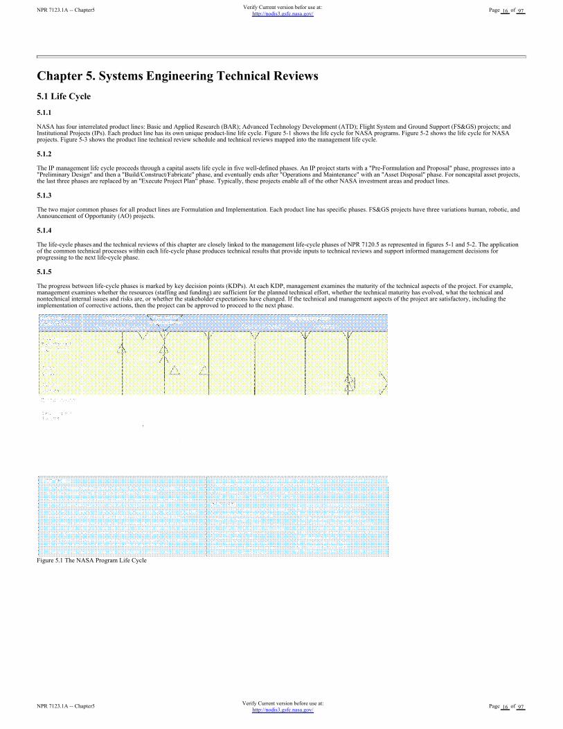
NASA has four interrelated product lines: Basic and Applied Research (BAR); Advanced Technology Development (ATD); Flight System and Ground Support (FS&GS) projects; andInstitutional Projects (IPs). Each product line has its own unique product-line life cycle. Figure 5-1 shows the life cycle for NASA programs. Figure 5-2 shows the life cycle for NASAprojects. Figure 5-3 shows the product line technical review schedule and technical reviews mapped into the management life cycle.
5.1.2
The IP management life cycle proceeds through a capital assets life cycle in five well-defined phases. An IP project starts with a "Pre-Formulation and Proposal" phase, progresses into a"Preliminary Design" and then a "Build/Construct/Fabricate" phase, and eventually ends after "Operations and Maintenance" with an "Asset Disposal" phase. For noncapital asset projects,the last three phases are replaced by an "Execute Project Plan" phase. Typically, these projects enable all of the other NASA investment areas and product lines.
5.1.3
The two major common phases for all product lines are Formulation and Implementation. Each product line has specific phases. FS&GS projects have three variations human, robotic, andAnnouncement of Opportunity (AO) projects.
5.1.4
The life-cycle phases and the technical reviews of this chapter are closely linked to the management life-cycle phases of NPR 7120.5 as represented in figures 5-1 and 5-2. The applicationof the common technical processes within each life-cycle phase produces technical results that provide inputs to technical reviews and support informed management decisions forprogressing to the next life-cycle phase.
5.1.5
The progress between life-cycle phases is marked by key decision points (KDPs). At each KDP, management examines the maturity of the technical aspects of the project. For example,management examines whether the resources (staffing and funding) are sufficient for the planned technical effort, whether the technical maturity has evolved, what the technical andnontechnical internal issues and risks are, or whether the stakeholder expectations have changed. If the technical and management aspects of the project are satisfactory, including theimplementation of corrective actions, then the project can be approved to proceed to the next phase.
Figure 5.1 The NASA Program Life Cycle
NPR 7123.1A -- Chapter5Verify Current version before use at:
http://nodis3.gsfc.nasa.gov/Page 16 of 97
NPR 7123.1A -- Chapter5Verify Current version befor use at:
http://nodis3.gsfc.nasa.gov/Page 16 of 97
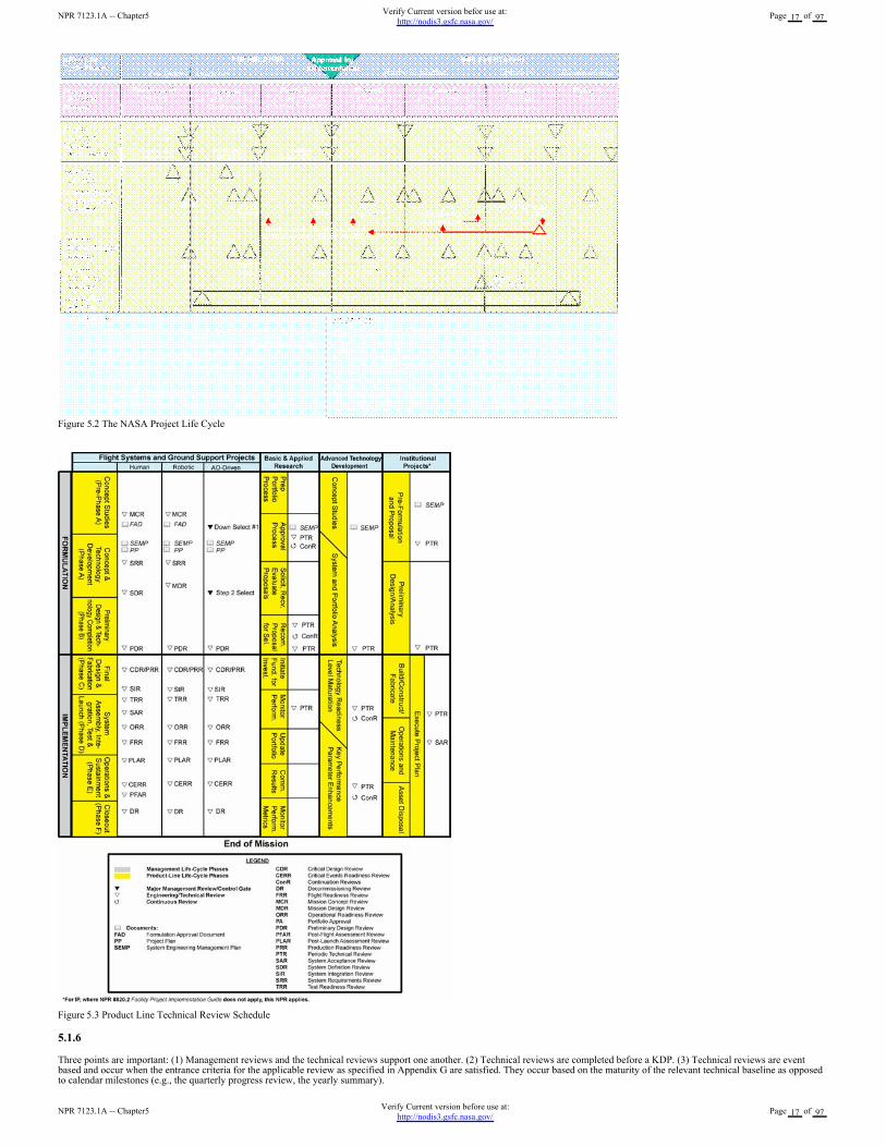
Figure 5.2 The NASA Project Life Cycle
Figure 5.3 Product Line Technical Review Schedule
5.1.6
Three points are important: (1) Management reviews and the technical reviews support one another. (2) Technical reviews are completed before a KDP. (3) Technical reviews are eventbased and occur when the entrance criteria for the applicable review as specified in Appendix G are satisfied. They occur based on the maturity of the relevant technical baseline as opposedto calendar milestones (e.g., the quarterly progress review, the yearly summary).
NPR 7123.1A -- Chapter5Verify Current version before use at:
http://nodis3.gsfc.nasa.gov/Page 17 of 97
NPR 7123.1A -- Chapter5Verify Current version befor use at:
http://nodis3.gsfc.nasa.gov/Page 17 of 97
5.2 Technical Review Requirements
5.2.1 Review Process and Practices
5.2.1.1
For each product line (BAR, ATD, IP, and FS&GS), technical efforts are monitored throughout the life cycle to ensure that the technical goals of the project are being achieved and that thetechnical direction of the project is appropriate.
5.2.1.2
Technical teams shall monitor technical effort through periodic technical reviews.
5.2.1.3
A technical review is an evaluation of the project, or element thereof, by a knowledgeable group for the purposes of:
a. Assessing the status of and progress toward accomplishing the planned activities.
b. Validating the technical tradeoffs explored and design solutions proposed.
c. Identifying technical weaknesses or marginal design and potential problems (risks) and recommending improvements and corrective actions.
d. Making judgments on the activities? readiness for the follow-on events, including additional future evaluation milestones to improve the likelihood of a successful outcome.
e. Making assessments and recommendations to the project team, Center, and Agency management.
f. Providing a historical record that can be referenced of decisions that were made during these formal reviews.
g. Assessing the technical risk status and current risk profile.
5.2.1.4
See NPR 7120.5 for major program and project reviews and independent reviews.
5.2.1.5
Technical reviews are used to evaluate the status of the technical progress and are supported by other equivalent technical discipline activities, including safety reviews.
5.2.1.6
The technical team shall ensure that system aspects represented or implemented in software are included in all technical reviews to demonstrate that project technical goals and progress arebeing achieved and that all NPR 7150.2 software review requirements are implemented.
5.2.2 Planning and Conduct
The technical team shall develop and document plans for technical reviews for use in the project planning process. The technical review schedule, as documented in the SEMP, will bereflected in the overall project plan described in NPR 7120.5. The results of each technical review will be used to update the technical review plan as part of the SEMP update process. Thereview plans, data, and results should be maintained and dispositioned as Federal records.
5.3 Minimum Required Set of Technical Reviews
5.3.1 Definition of Minimum Required Reviews
5.3.1.1
The minimum set of required technical reviews applies to all current and future NASA FS&GS and IP programs and projects as defined in section P.2 of this document (includingspacecraft, launch vehicles, instruments developed for space flight programs and projects, designated research and technology developments to be incorporated by space flight programs andprojects, critical technical facilities specifically developed or significantly modified for space flight systems, information systems and technology that support space flight programs andprojects, and ground systems that are in direct support of space flight operations). Between each life-cycle phase, a program or project goes through KDPs preceded by one or more reviewsthat enable a disciplined approach to assessing programs? and projects? readiness to progress to the next phase. Allowances are made within a phase for the differences between human androbotic FS&GS projects. Additional description of technical reviews is provided in the NASA Systems Engineering Handbook (SP-6105). (For more information on program and projectlife cycles and management reviews, see the appropriate NPR, e.g., NPR 7120.5.)
5.3.1.2
The technical team shall address the entrance and success criteria listed in Appendix G for applicability to the respective reviews.
5.3.1.3
The technical team shall execute the required Program/System Requirements Review (P/SRR) and Program Approval Review (PAR) in accordance with the review entry and success criteriadefined in tables G-1 and G-2 of Appendix G.
5.3.1.4
The technical team shall execute the required program technical reviews in accordance with the following timeline: P/SRR before KDP 0 and PAR before KDP 1.
5.3.1.5
For human FS&GS projects, the technical team shall execute the following required minimum set of technical reviews in accordance with the review entry and success criteria defined intables G-3, G-4, G-6, G-7, G-8, and G-10 through G-18 of Appendix G: Mission Concept Review (MCR), System Requirements Review (SRR), System Definition Review (SDR),Preliminary Design Review (PDR), Critical Design Review (CDR), System Integration Review (SIR), Test Readiness Review (TRR), System Acceptance Review (SAR), OperationalReadiness Review (ORR), Flight Readiness Review (FRR), Post-Launch Assessment Review (PLAR), Critical Event Readiness Review (CERR), Post-Flight Assessment Review (PFAR),and Decommissioning Review (DR). (For more information on program and project life cycles and management reviews, see the appropriate NPR, e.g., NPR 7120.5.)
5.3.1.6
For robotic FS&GS projects, the technical team shall execute and document the following minimum required technical reviews: the MCR, SRR, Mission Definition Review (MDR), PDR,CDR, SIR, TRR, ORR, FRR, PLAR, CERR, and DR in accordance with the review entry and success criteria given in tables G-3, G-4, G-5, G-7, G-8, G-10, G-11, G-13 through G-16, andG-18 of Appendix G. Robotic projects can combine the SRR and MDR based on size and level of risk. If the two reviews are conducted separately, Table G-4 will be used for the SRR andTable G-5 will be used for the MDR. If the two reviews are combined, the entrance and success criteria for both SRR and MDR will be combined for this single review.
5.3.1.7
The technical team shall also execute a Production Readiness Review (PRR) as an additional technical review for both human and robotic FS&GS projects developing or acquiring multipleor similar systems greater than three (or as determined by the project) in accordance with the review entry and success criteria defined in Table G-9 of Appendix G. Any project producingend products with three or less units will still perform the required CDR. The CDR will include production considerations when a PRR is not performed.
5.3.1.8
The technical team shall execute the required FS&GS project technical reviews in accordance with the following timelines:
a. MCR prior to KDP A.
b. Human FS&GS project SRR prior to SDR and robotic missions SRR and MDR prior to KDP B.
c. Human FS&GS project SDR prior to KDP B.
d. PDR prior to KDP C.
NPR 7123.1A -- Chapter5Verify Current version before use at:
http://nodis3.gsfc.nasa.gov/Page 18 of 97
NPR 7123.1A -- Chapter5Verify Current version befor use at:
http://nodis3.gsfc.nasa.gov/Page 18 of 97
e. CDR prior to starting fabrication of system end products and SIR.
f. PRR prior to starting fabrication of system end products for projects requiring multiple units.
g. SIR prior to KDP D.
h. TRR prior to starting product verification and product validation testing.
i. Human FS&GS project SAR after completion of KDP D.
j. ORR after SAR or KDP D and before FRR.
k. FRR prior to KDP E.
l. PLAR after system end product launch.
m. CERR after PLAR and before KDP F.
n. Human FS&GS project PFAR at end of flight and before KDP F.
o. DR after KDP F.
5.3.1.9
The assigned technical team shall accomplish the monitoring function for flight-related ATD projects using appropriately defined and conducted periodic technical reviews (PTRs) andcontinuation reviews (CRs). (See Figure 5-3.)
5.3.1.10
The assigned technical team shall accomplish the monitoring function for IPs using PTR and SAR. (See Figure 5-3.)
5.3.1.11
Reviews are considered complete when the following are accomplished:
a. Agreement exists for the disposition of all Review Item Discrepancies (RIDs) and Request for Actions (RFA).
b. The review board report and minutes are complete and distributed.
c. Agreement exists on a plan to address the issues and concerns in the review board?s report.
d. Agreement exists on a plan for addressing the actions identified out of the review.
e. Liens against the review results are closed, or an adequate and timely plan exists for their closure.
f. Differences of opinion between the project under review and the review board(s) have been resolved, or a timely plan exists to resolve the issues.
g. A report is given by the review board chairperson to the appropriate management and governing program management committees (PMCs) charged with oversight of the project.
h. Appropriate procedures and controls are instituted to ensure that all actions from reviews are followed and verified through implementation to closure.
NPR 7123.1A -- Chapter5Verify Current version before use at:
http://nodis3.gsfc.nasa.gov/Page 19 of 97
NPR 7123.1A -- Chapter5Verify Current version befor use at:
http://nodis3.gsfc.nasa.gov/Page 19 of 97
Chapter 6. Systems Engineering Management Plan
6.1 Systems Engineering Management Plan Function
6.1.1
The primary function of the SEMP is to provide the basis for implementing the technical effort and communicating what will be done, by whom, when, where, cost drivers, and why it isbeing done. In addition, the SEMP identifies the roles and responsibility interfaces of the technical effort and how those interfaces will be managed.
6.1.2
The SEMP is the vehicle that documents and communicates the technical approach including the application of the common technical processes; resources to be used; and key technicaltasks, activities, and events along with their metrics and success criteria. The SEMP communicates the technical effort that will be performed by the assigned technical team to the teamitself, managers, customers, and other stakeholders. Whereas the primary focus is on the applicable phase in which the technical effort will be done, the planning extends to a summary of thetechnical efforts that are planned for future applicable phases.
6.1.3
The SEMP is a "living" and tailorable document that captures a project?s current and evolving systems engineering strategy and its relationship with the overall project management effortthroughout the life cycle of the system. The SEMP?s purpose is to guide all technical aspects of the project.
6.1.4
The SEMP is consistent with higher level SEMPs and the project plan in accordance with NPR 7120.5.
6.1.5
The content of a SEMP for an in-house technical effort may differ from an external technical effort. For an external technical effort, the SEMP should include details on developingrequirements for source selection, monitoring performance, and transferring and integrating externally produced products to NASA. (See Appendix D for further details.)
6.1.6
The SEMP provides the basis for generating the contractor engineering plan.
6.2 Roles and Responsibilities
6.2.1
Working with the program/project manager, the technical team shall determine the appropriate level within the system structure at which SEMPs are developed, taking into account factorssuch as number and complexity of interfaces, operating environments, and risk factors.
6.2.2
The technical team shall baseline the SEMP per the Center?s Implementation Plan incorporating the content of Appendix D, Systems Engineering Management Plan, prior to completion ofPhase A in the program life cycle or the equivalent milestone. At the discretion of the PM and the DGA, for a small project the material in the SEMP can be placed in the project plan?stechnical summary and the annotated outline in Appendix D used as a topic guide. As changes occur, the SEMP will be updated by the technical team, reviewed and concurred with by thePM, and presented at subsequent milestone reviews or their equivalent.
6.2.3
The DGA shall review and approve or disapprove the SEMP at each major milestone review or its equivalent.
6.2.4
The assigned technical team shall establish the initial SEMP early in the Formulation phase and update it as necessary to reflect changes in scope or improved technical development.
6.2.5
The technical team shall ensure that any technical plans and discipline plans describe how the technical activities covered in the plans are consistent with the SEMP and are accomplished asfully integrated parts of the technical effort.
6.2.6
The technical team shall ensure that the project?s software development/management plan describes how the software activities are consistent with the SEMP and are accomplished as fullyintegrated parts of the technical effort. The required content of the project?s software development/management plan is provided in NPR 7150.2, dependent upon the classification ofsoftware items.
NPR 7123.1A -- Chapter6Verify Current version before use at:
http://nodis3.gsfc.nasa.gov/Page 20 of 97
NPR 7123.1A -- Chapter6Verify Current version befor use at:
http://nodis3.gsfc.nasa.gov/Page 20 of 97
Appendix A. Definitions
A.1 Activity:
(1) Any of the project components or research functions that are executed to deliver a product or service or provide support or insight to mature technologies. (2) A set of tasks thatdescribe the technical effort to accomplish a process and help generate expected outcomes.
A.2 Advanced Technology Development:
ATD is one of four interrelated NASA product lines. ATD programs and projects are investments that produce entirely new capabilities or that help overcome technical limitations ofexisting systems. ATD is seen as a bridge between BAR and actual application in NASA, such as FS&GS projects or elsewhere. ATD projects typically fall within a Technology ReadinessLevel (TRL) range of 4 to 6.
A.3 Baseline:
An agreed-to set of requirements, designs, or documents that will have changes controlled through a formal approval and monitoring process.
A.4 Basic and Applied Research:
Research whose results expand the knowledge base, provide scientific and technological breakthroughs that are immediately applicable, or evolve into an advanced technology development(ATD). Basic research addresses the need for knowledge, while applied research directs this new knowledge toward a practical application.
A.5 Component Facilities:
Complexes that are geographically separated from the NASA Center or institution to which they are assigned.
A.6 Contractor:
For the purposes of this NPR, a "contractor" is an individual, partnership, company, corporation, association, or other service having a contract with the Agency for the design,development, manufacture, maintenance, modification, operation, or supply of items or services under the terms of a contract to a program or project within the scope of this NPR. Researchgrantees, research contractors, and research subcontractors are excluded from this definition.
A.7 Critical Event
(also referred to as a Key Event in this NPR): An event that requires monitoring in the projected life cycle of a product that will generate critical requirements that would affect systemdesign, development, manufacture, test, and operations (such as with an MOE, MOP, Technical Performance Measure (TPM), or KPP).
A.8 Customer:
The organization or individual that has requested a product and will receive the product to be delivered. The customer may be an end user of the product, the acquiring agent for the enduser, or the requestor of the work products from a technical effort. Each product within the system hierarchy has a customer.
A.9 Decision Authority:
The Agency’s responsible individual who authorizes the transition at a KDP to the next life-cycle phase for a program/project.
A.10 Designated Governing Authority:
The management entity above the program, project, or activity level with technical oversight responsibility.
A.11 Enabling Products:
The life-cycle support products and services (e.g., production, test, deployment, training, maintenance, and disposal) that facilitate the progression and use of the operational end productthrough its life cycle. Since the end product and its enabling products are interdependent, they are viewed as a system. Project responsibility thus extends to responsibility for acquiringservices from the relevant enabling products in each life-cycle phase. When a suitable enabling product does not already exist, the project that is responsible for the end product can also beresponsible for creating and using the enabling product.
A.12 Entry Criteria:
Minimum accomplishments each project needs to fulfill to enter into the next life-cycle phase or level of technical maturity.
A.13 Establish (with respect to each process in Chapter 3)
The act of developing policy, work instructions or procedures to implement process activities.
A.14 Exit Criteria
Specific accomplishments that should be satisfactorily demonstrated before a project can progress to the next product-line life-cycle phase.
A.15 Expectation:
Statements of needs, desires, capabilities and wants that are not expressed as a requirement (not expressed as a "shall" statement) is to be referred to as an "expectation." Once the set ofexpectations from applicable stakeholders is collected, analyzed, and converted into a "shall" statement, the "expectation" becomes a "requirement." Expectations can be stated in eitherqualitative (nonmeasurable) or quantitative (measurable) terms. Requirements are always stated in quantitative terms. Expectations can be stated in terms of functions, behaviors, orconstraints with respect to the product being engineered or the process used to engineer the product.
A.16 Flight Systems and Ground Support
FS&GS is one of four interrelated NASA product lines. FS&GS projects result in the most complex and visible of NASA investments. To manage these systems, the Formulation andImplementation phases for FS&GS projects follow the NASA project life-cycle model consisting of phases A (Concept Development) through F (Closeout). Primary drivers for FS&GSprojects are safety and mission success.
NPR 7123.1A -- AppendixAVerify Current version before use at:
http://nodis3.gsfc.nasa.gov/Page 21 of 97
NPR 7123.1A -- AppendixAVerify Current version befor use at:
http://nodis3.gsfc.nasa.gov/Page 21 of 97
A.17 Formulation Phase
The first part of the NASA management life cycle defined in NPR 7120.5 where system requirements are baselined, feasible concepts are determined, a system definition is baselined for theselected concept(s), and preparation is made for progressing to the Implementation phase.
A.18 Implementation Phase
The part of the NASA management life cycle defined in NPR 7120.5 where the detailed design of system products is completed and the products to be deployed are fabricated, assembled,integrated and tested; and the products are deployed to their customers or users for their assigned use or mission.
A.19 Institutional Projects:
Projects that build or maintain the institutional infrastructure to support other NASA product lines.
A.20 Information Systems and Technology Projects:
All NASA projects for or including the development, modernization, enhancement, or steady-state operations of information systems and technologies. This includes projects for orcontaining computer and/or communications systems, ancillary equipment, hardware, software applications, firmware, or networks for the generation, processing, storage, access,manipulation, exchange or safeguarding of information.
A.21 Iterative:
Application of a process to the same product or set of products to correct a discovered discrepancy or other variation from requirements. (See "recursive" and "repeatable.")
A.22 Key Decision Point
The event at which the Decision Authority determines the readiness of a program/project to progress to the next phase of the life cycle (or to the next KDP).
A.23 Key Event:
See Critical Event.
A.24 Key Performance Parameters
Those capabilities or characteristics (typically engineering-based or related to safety or operational performance) considered most essential for successful mission accomplishment. Failureto meet a KPP threshold can be cause for the project, system, or advanced technology development to be reevaluated or terminated or for the system concept or the contributions of theindividual systems to be reassessed. A project?s KPPs are identified and quantified in the project baseline. (See Technical Performance Parameter.)
A.25 Logical Decomposition
The decomposition of the defined technical requirements by functions, time, and behaviors to determine the appropriate set of logical models and related derived technical requirements.Models may include functional flow block diagrams, timelines, data control flow, states and modes, behavior diagrams, operator tasks, and functional failure modes.
A.26 Maintain
(with respect to establishment of processes in Chapter 3): The act of planning the process, providing resources, assigning responsibilities, training people, managing configurations,identifying and involving stakeholders, and monitoring process effectiveness.
A.27 Measure of Effectiveness
A measure by which a stakeholder?s expectations will be judged in assessing satisfaction with products or systems produced and delivered in accordance with the associated technicaleffort. The MOE is deemed to be critical to not only the acceptability of the product by the stakeholder but also critical to operational/mission usage. An MOE is typically qualitative innature or not able to be used directly as a "design-to" requirement.
A.28 Measure of Performance:
A quantitative measure that, when met by the design solution, will help ensure that an MOE for a product or system will be satisfied. These MOPs are given special attention during designto ensure that the MOEs to which they are associated are met. There are generally two or more measures of performance for each MOE.
A.29 Other Interested Parties:
A subset of "stakeholders," other interested parties are groups or individuals that are not customers of a planned technical effort but may be affected by the resulting product, the manner inwhich the product is realized or used, or have a responsibility for providing life-cycle support services. A subset of "stakeholders." (See Stakeholder.)
A.30 Peer Review:
Independent evaluation by internal or external subject matter experts who do not have a vested interest in the work product under review. Peer reviews can be planned, focused reviewsconducted on selected work products by the producer?s peers to identify defects and issues prior to that work product moving into a milestone review or approval cycle.
A.31 Process:
A set of activities used to convert inputs into desired outputs to generate expected outcomes and satisfy a purpose.
A.32 Product:
A part of a system consisting of end products that perform operational functions and enabling products that perform life-cycle services related to the end product or a result of the technicalefforts in the form of a work product (e.g., plan, baseline, or test result).
A.33 Product-Based WBS Model:
See WBS model.
A.34 Product Realization:
The act of making, buying, or reusing a product, or the assembly and integration of lower level realized products into a new product, as well as the verification and validation that theproduct satisfies its appropriate set of requirements and the transition of the product to its customer.
NPR 7123.1A -- AppendixAVerify Current version before use at:
http://nodis3.gsfc.nasa.gov/Page 22 of 97
NPR 7123.1A -- AppendixAVerify Current version befor use at:
http://nodis3.gsfc.nasa.gov/Page 22 of 97
A.35 Program
A strategic investment by a mission directorate (or mission support office) that has defined goals, objectives, architecture, funding level, and a management structure that supports one ormore projects.
A.36 Program Commitment Agreement
The contract between the Administrator and the cognizant Mission Directorate Associate Administrator (MDAA) or Mission Support Office Director (MSOD) for implementation of aprogram.
A.37 Project
(1) A specific investment having defined goals, objectives, requirements, life-cycle cost, a beginning, and an end. A project yields new or revised products or services that directly addressNASA?s strategic needs. They may be performed wholly in-house; by Government, industry, academia partnerships; or through contracts with private industry. (2) A unit of workperformed in programs, projects, and activities.
A.38 Realized Product:
The desired output from the application of the four Product Realization Processes. The form of this product is dependent on the phase of the product-line life cycle and the phase exitcriteria.
A.39 Recursive:
Value is added to the system by the repeated application of processes to design next lower layer system products or to realize next upper layer end products within the system structure. Thisalso applies to repeating application of the same processes to the system structure in the next life-cycle phase to mature the system definition and satisfy phase exit criteria.
A.40 Relevant Stakeholder
See Stakeholder.
A.41 Repeatable:
A characteristic of a process that can be applied to products at any level of the system structure or within any life-cycle phase.
A.42 Requirement
The agreed upon need, desire, want, capability, capacity, or demand for personnel, equipment, facilities, or other resources or services by specified quantities for specific periods of time orat a specified time expressed as a "shall" statement. Acceptable form for a requirement statement is individually clear, correct, feasible to obtain, unambiguous in meaning, and can bevalidated at the level of the system structure at which stated. In pairs of requirement statements or as a set, collectively, they are not redundant, are adequately related with respect to termsused, and are not in conflict with one another.
A.43 Risk:
The combination of the probability that a program or project will experience an undesired event (some examples include a cost overrun, schedule slippage, safety mishap, health problem,malicious activities, environmental impact, failure to achieve a needed scientific or technological breakthrough or mission success criteria) and the consequences, impact, or severity of theundesired event, were it to occur. Both the probability and consequences may have associated uncertainties. (Reference 7120.5.)
A.44 Software
As defined in NPD 2820.1, NASA Software Policy.
A.45 Specification
A document that prescribes, in a complete, precise, verifiable manner, the requirements, design, behavior, or characteristics of a system or system component.
A.46 Stakeholder
A group or individual who is affected by or is in some way accountable for the outcome of an undertaking. The term "relevant stakeholder" is a subset of the term "stakeholder" anddescribes people or roles that are designated in a plan for stakeholder involvement. Since "stakeholder" may describe a very large number of people, a lot of time and effort would beconsumed by attempting to deal with all of them. For this reason, "relevant stakeholder" is used in most practice statements to describe the people identified to contribute to a specific task.There are two main classes of stakeholders. See "customers" and "other interested parties."
A.47 Success Criteria
Specific accomplishments that must be satisfactorily demonstrated to meet the objectives of a technical review so that a technical effort can progress further in the life cycle. Success criteriaare documented in the corresponding technical review plan.
A.48 Surveillance-Type Projects:
A project where prime or external contractors do the majority of the development effort that requires NASA oversight.
A.49 System
(a) The combination of elements that function together to produce the capabil-ity to meet a need. The elements include all hardware, software, equipment, facilities, personnel, processes,and procedures needed for this purpose. (Refer to NPR 7120.5.) (b) The end product (which performs operational functions) and enabling products (which provide life-cycle supportservices to the operational end products) that make up a system. (See WBS definition.)
A.50 Systems Approach
The application of a systematic, disciplined engineering approach that is quantifiable, recursive, iterative, and repeatable for the development, operation, and maintenance of systemsintegrated into a whole throughout the life cycle of a project or program.
A.51 Systems Engineering Engine:
The SE model shown in Figure 3-1 provides the 17 technical processes and their relationship with each other. The model is called an "SE engine" in that the appropriate set of processes areapplied to the products being engineered to drive the technical effort.
NPR 7123.1A -- AppendixAVerify Current version before use at:
http://nodis3.gsfc.nasa.gov/Page 23 of 97
NPR 7123.1A -- AppendixAVerify Current version befor use at:
http://nodis3.gsfc.nasa.gov/Page 23 of 97
A.52 Systems Engineering Management Plan
The SEMP identifies the roles and responsibility interfaces of the technical effort and how those interfaces will be managed. The SEMP is the vehicle that documents and communicates thetechnical approach, including the application of the common technical processes; resources to be used; and key technical tasks, activities, and events along with their metrics and successcriteria.
A.53 System Safety Engineering
The application of engineering and management principles, criteria, and techniques to achieve acceptable mishap risk, within the constraints of operational effectiveness and suitability,time, and cost, throughout all phases of the system life cycle.
A.54 System Structure
A system structure is made up of a layered structure of product-based WBS models. (See WBS definition.)
A.55 Tailoring
The documentation and approval of the adaptation of the process and approach to complying with requirements underlying the specific program or projects. Tailoring considerations includesystem size and complexity, level of system definition detail, scenarios and missions, constraints and requirements, technology base, major risk factors, and organizational best practicesand strengths. Critical project considerations (e.g., public safety, security, litigation exposures) may preclude tailoring out required process activities, regardless of cost, manpoweravailable, or other considerations. (From Systems Engineering Fundamentals, Defense Acquisition University, January 2001.)
A.56 Technical Performance Measures:
The set of critical or key performance parameters that are monitored by comparing the current actual achievement of the parameters with that anticipated at the current time and on futuredates. Used to confirm progress and identify deficiencies that might jeopardize meeting a system requirement. Assessed parameter values that fall outside an expected range around theanticipated values indicate a need for evaluation and corrective action. Technical performance measures are typically selected from the defined set of Measures of Performance (MOPs).
A.57 Technical Team:
A group of multidisciplinary individuals with appropriate domain knowledge, experience, competencies, and skills assigned to a specific technical task.
A.58 Technology Readiness Level
Provides a scale against which to measure the maturity of a technology. TRLs range from 1, Basic Technology Research, to 9, Systems Test, Launch and Operations. Typically, a TRL of 6(i.e., technology demonstrated in a relevant environment) is required for a technology to be integrated into an SE process.
A.59 Technical Risk:
Risk associated with the achievement of a technical goal, criterion, or objective. It applies to undesired consequences related to technical performance, human safety, mission assets, orenvironment.
A.60 Transition:
The act of delivery or moving of a product from the location where the product has been implemented or integrated, as well as verified and validated, to a customer. This act can includepackaging, handling, storing, moving, transporting, installing, and sustainment activities.
A.61 Transition Process
In the context of this SE NPR, the Transition Process transfers a product to a customer higher in the system structure for assembly and integration into a higher level product or to theintended end use customer.
A.62 Validation (of a product):
Proof that the product accomplishes the intended purpose. Validation may be determined by a combination of test, analysis, and demonstration.
A.63 Validated Requirements
A set of requirements that are well-formed (clear and un-ambiguous), complete (agrees with customer and stakeholder needs and expectations), consistent (conflict free), and individuallyverifiable and traceable to a higher-level requirement or goal.
A.64 Verification (of a product>):
Proof of compliance with specifications. Verification may be determined by test, analysis, demonstration, and inspection.
A.65 Waiver:
A documented agreement intentionally releasing a program or project from meeting a requirement. (Some Centers use deviations prior to Implementation and waivers duringImplementation).
A.66 WBS Model:
Model that describes a system that consists of end products and their subsystems (perform the operational functions of the system), the supporting or enabling products (for development;fabrication, assembly, integration, and test; operations; sustainment; and end-of-life product disposal or recycling), and any other work products (plans, baselines) required for thedevelopment of the system. See the example product-based WBS for an aircraft system and one of its subsystems (navigation subsystem) below:
NPR 7123.1A -- AppendixAVerify Current version before use at:
http://nodis3.gsfc.nasa.gov/Page 24 of 97
NPR 7123.1A -- AppendixAVerify Current version befor use at:
http://nodis3.gsfc.nasa.gov/Page 24 of 97
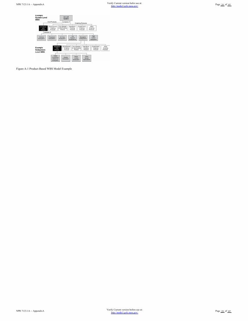
Figure A-1 Product-Based WBS Model Example
NPR 7123.1A -- AppendixAVerify Current version before use at:
http://nodis3.gsfc.nasa.gov/Page 25 of 97
NPR 7123.1A -- AppendixAVerify Current version befor use at:
http://nodis3.gsfc.nasa.gov/Page 25 of 97
Appendix B. Acronyms
AO Announcement of Opportunity
ATD Advanced Technology Development
BAR Basic and Applied Research
CDR Critical Design Review
CERR Critical Event Readiness Review
CM Configuration Management
CMM Capability Maturity Model®
CMMI Capability Maturity Model® IntegrationSM
CoF Construction of Facilities
ConR Continuation Reviews
DGA Designated Governing Authority
DR Decommissioning Review
ECP Engineering Change Proposal
ECR Environmental Compliance and Restoration
EEE Electrical, Electronic, and Electromechanical
EMC Electromagnetic Compatibility
EMI Electromagnetic Interference
EPR Engineering Peer Reviews
FAD Formulation Approval Document
FRR Flight Readiness Review
FS&GS Flight Systems and Ground Support
ICD Interface Control Document
ICWG Interface Control Working Group
INCOSE International Council on Systems Engineering
IP Institutional Projects
IPD Integrated Product Development
IPPD Integrated Product and Process Development
KDP Key Decision Point
KPP Key Performance Parameter
LLIL Limited Life Items List
MCR Mission Concept Review
MD Mission Directorates
MDAA Mission Directorate Associate Administrator
MDR Mission Design Review
MOE Measures of Effectiveness
MOP Measures of Performance
MSO Mission Support Office
MSOD Mission Support Office Director
NODIS NASA On-Line Directives Information System
NPD NASA Policy Directive
NPR NASA Procedural Requirements
OCE Office of the Chief Engineer
ORR Operational Readiness Review
OSMA Office of Safety and Mission Assurance
PA Portfolio Approval
PAR Program Approval Review
PDR Preliminary Design Review
PFAR Post Flight Assessment Review or Post Flight Anomaly Records
PLAR Post Launch Assessment Review
PM Program or Project Manager
PMP Program Management Plan
PNAR Pre-Non-Advocate Review
PP Project Plan
PR Procedural Requirements
NPR 7123.1A -- AppendixBVerify Current version before use at:
http://nodis3.gsfc.nasa.gov/Page 26 of 97
NPR 7123.1A -- AppendixBVerify Current version befor use at:
http://nodis3.gsfc.nasa.gov/Page 26 of 97
PR Procedural Requirements
PRA Probabilistic Risk Assessment
PRR Production Readiness Review
P/SRR Program/System Requirements Review
PTR Periodic Technical Reviews
RFA Requests for Action
RFP Request for Proposal
RID Review Item Discrepancy
SAR System Acceptance Review
SDP Software Development Plan
SDR System Definition Review
SE Systems Engineering
SEMP Systems Engineering Management Plan
SE NPR Systems Engineering NASA Procedural Requirements
SEWG Systems Engineering Working Group
SIR System Integration Review
S&MA Safety and Mission Assurance
SP Special Publication
SRR System Requirements Review
TPM Technical Performance Measure
TRL Technology Readiness Level
TRR Test Readiness Review
V&V Verification and Validation
WBS Work Breakdown Structure
NPR 7123.1A -- AppendixBVerify Current version before use at:
http://nodis3.gsfc.nasa.gov/Page 27 of 97
NPR 7123.1A -- AppendixBVerify Current version befor use at:
http://nodis3.gsfc.nasa.gov/Page 27 of 97

Appendix C. Practices for Common Technical Processes
a. This appendix contains best typical practices as extracted from industry and national and international standards and as found within the Agency. The practices may be used byCenters in preparing directives, policies, rules, work instructions, and other documents implementing SE processes. The practices of this appendix may also be used in the futureassessments of those plans and processes to provide feedback to the OCE and Centers on the strengths and weaknesses in the Centers? implementation of this SE NPR. These practices canbe expanded and updated as necessary.
b. Each process is described in terms of purpose, inputs, outputs, and activities. Notes are provided to further explain a process and to help understand the best practices included. Adescriptive figure is also provided for each process to illustrate notional relationships between activities within a process and the sources of inputs and destinations of outputs. Figures inthis appendix are not intended to include all possible inputs, outputs, or intermediate work products.[2]
C.1 System Design Processes
a. There are four system design processes applied to each product-based WBS model from the top to the bottom of the system structure: (1) Stakeholder Expectation Definition, (2)Technical Requirements Definition, (3) Logical Decomposition, and (4) Design Solution Definition. (See Figure 3-2.)
b. During the application of these four processes to a WBS model it is expected that there will be a need to apply activities from other processes yet to be completed in this set ofprocesses and to repeat process activities already performed in order to arrive at an acceptable set of requirements and solutions. There will also be a need to interact with the technicalmanagement processes to aid in identifying and resolving issues and making decisions between alternatives.
c. For software products, the technical team should refer to NPR 7150.2 software design requirements. The technical team should also ensure that the process implementations complywith NPR 7150.2 software product realization requirements for software aspects of the system.
C.1.1 Stakeholder Expectations Definition Process
C.1.1.1 Purpose
The stakeholder expectations definition process is used to elicit and define use cases, scenarios, operational concepts, and stakeholder expectations for the applicable product-line life-cyclephases and WBS model. This includes requirements for:
a. operational end products and life-cycle-enabling products of the WBS model;
b. expected skills and capabilities of operators or users;
c. expected number of simultaneous users;
d. system and human performance criteria;
e. technical authority, standards, regulations, and laws;
f. factors such as safety, quality, security, context of use by humans, reliability, availability, maintainability, electromagnetic compatibility, interoperability, testability, transportability,supportability, usability, and disposability; and
g. local management constraints on how work will be done (e.g., operating procedures).
The baselined stakeholder expectations are used for validation of the WBS model end product during product realization.
C.1.1.2 Inputs and Sources:
a. Customer expectations (from users and program and/or project).
b. Other stakeholder expectations (from project and/or other interested parties of the WBS model products recursive loop).
c. Customer flow-down requirements from previous level WBS model products (from Design Solution Definition Process recursive loop and Requirements Management and InterfaceManagement Processes).
Note: This would include requirements for initiating enabling product development to provide appropriate life-cycle support products and services to the mission, operational, or researchend product of the WBS model.
C.1.1.3 Outputs and Destinations:
a. Set of validated stakeholder expectations, including interface requirements (to Technical Requirements Definition, Requirements Management, and Interface Management Processes).
b. Baseline operational concepts (to Technical Requirements Definition Process and Configuration Management Processes).
c. Baseline set of enabling product support strategies (to Technical Requirements Definition Process and Configuration Management Processes).
d. Measures of Effectiveness (MOEs) (to Technical Requirements Definition Process and Technical Data Management Process).
C.1.1.4 Activities
For the WBS model in the system structure, the following activities are typically performed:
a. Establish a list that identifies customers and other stakeholders that have an interest in the system and its products.
b. Elicit customer and other stakeholder expectations (needs, wants, desires, capabilities, external interfaces, and constraints) from the identified stakeholders.
c. Establish operational concepts and support strategies based on stakeholder expected use of the system products over the system?s life.
Note: Defined scenarios and operational concepts include functionality and performance of intended uses and relevant boundaries, constraints, and environments in which the product(s)will operate. Support strategies include provisions for fabrication, test, deployment, operations, sustainment, and disposal as appropriate.
d. Define stakeholder expectations in acceptable statements that are complete sentences and have the following characteristics: (1) individually clear, correct, and feasible to satisfy; notstated as to how it is to be satisfied; implementable; only one interpretation of meaning; one actor-verb-object expectation; and can be validated at the level of the system structure at which itis stated; and (2) in pairs or as a set there is an absence of redundancy, consistency with respect to terms used, not in conflict with one another, and do not contain stakeholder expectationsof questionable utility or that have an unacceptable risk of satisfaction.
e. Analyze stakeholder expectation statements to establish a set of measures (MOEs) by which overall system or product effectiveness will be judged and customer satisfaction will bedetermined.
Note: A set of MOEs is selected from the set of defined stakeholder expectation statements. It represents an expectation that is critical to the success of the system, and failure to satisfythese measures will cause the stakeholder to deem the system unacceptable. Examples of typical MOEs are weight, availability, mobility, user/operator comfort, CPU capacity, andparameters associated with critical events during operations. Whereas weight is generally stated in quantitative terms and can be easily allocated to lower level system products, other MOEsmay be qualitative or not easily allocated and thus will need measures of performance (MOPs) derived that can be used as design-to requirements. MOPs are derived during technicalrequirements definition process activities.
f. Validate that the resulting set of stakeholder expectation statements are upward and downward traceable to reflect the elicited set of stakeholder expectations and that any anomaliesidentified are resolved.
g. Obtain commitments from customer and other stakeholders that the resultant set of stakeholder expectation statements is acceptable.
Note: This can be done through the equivalent of a systems requirement review with appropriate formality as a function of the location of the product in the system structure, the agreementaffecting the development effort, and the type of NASA product ranging from applied research to FS&GS.
NPR 7123.1A -- AppendixCVerify Current version before use at:
http://nodis3.gsfc.nasa.gov/Page 28 of 97
NPR 7123.1A -- AppendixCVerify Current version befor use at:
http://nodis3.gsfc.nasa.gov/Page 28 of 97
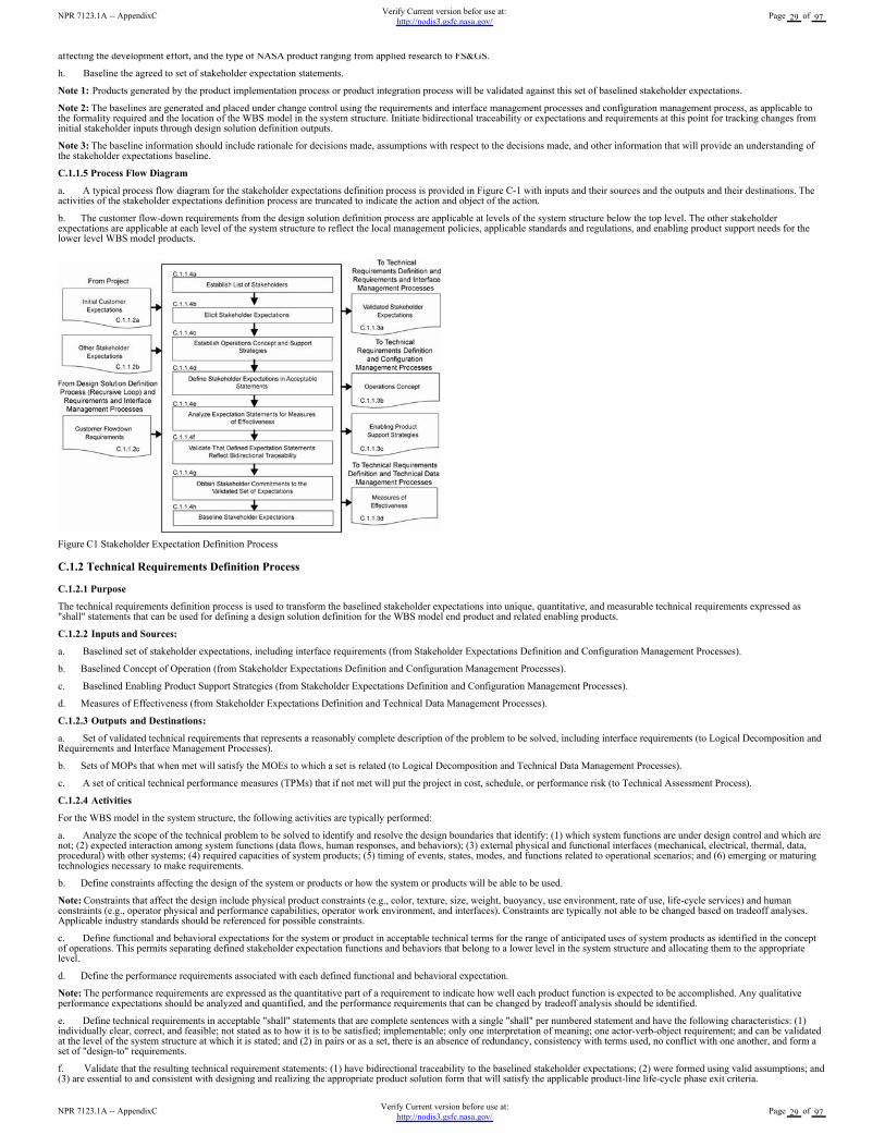
affecting the development effort, and the type of NASA product ranging from applied research to FS&GS.
h. Baseline the agreed to set of stakeholder expectation statements.
Note 1: Products generated by the product implementation process or product integration process will be validated against this set of baselined stakeholder expectations.
Note 2: The baselines are generated and placed under change control using the requirements and interface management processes and configuration management process, as applicable tothe formality required and the location of the WBS model in the system structure. Initiate bidirectional traceability or expectations and requirements at this point for tracking changes frominitial stakeholder inputs through design solution definition outputs.
Note 3: The baseline information should include rationale for decisions made, assumptions with respect to the decisions made, and other information that will provide an understanding ofthe stakeholder expectations baseline.
C.1.1.5 Process Flow Diagram
a. A typical process flow diagram for the stakeholder expectations definition process is provided in Figure C-1 with inputs and their sources and the outputs and their destinations. Theactivities of the stakeholder expectations definition process are truncated to indicate the action and object of the action.
b. The customer flow-down requirements from the design solution definition process are applicable at levels of the system structure below the top level. The other stakeholderexpectations are applicable at each level of the system structure to reflect the local management policies, applicable standards and regulations, and enabling product support needs for thelower level WBS model products.
Figure C1 Stakeholder Expectation Definition Process
C.1.2 Technical Requirements Definition Process
C.1.2.1 Purpose
The technical requirements definition process is used to transform the baselined stakeholder expectations into unique, quantitative, and measurable technical requirements expressed as"shall" statements that can be used for defining a design solution definition for the WBS model end product and related enabling products.
C.1.2.2 Inputs and Sources:
a. Baselined set of stakeholder expectations, including interface requirements (from Stakeholder Expectations Definition and Configuration Management Processes).
b. Baselined Concept of Operation (from Stakeholder Expectations Definition and Configuration Management Processes).
c. Baselined Enabling Product Support Strategies (from Stakeholder Expectations Definition and Configuration Management Processes).
d. Measures of Effectiveness (from Stakeholder Expectations Definition and Technical Data Management Processes).
C.1.2.3 Outputs and Destinations:
a. Set of validated technical requirements that represents a reasonably complete description of the problem to be solved, including interface requirements (to Logical Decomposition andRequirements and Interface Management Processes).
b. Sets of MOPs that when met will satisfy the MOEs to which a set is related (to Logical Decomposition and Technical Data Management Processes).
c. A set of critical technical performance measures (TPMs) that if not met will put the project in cost, schedule, or performance risk (to Technical Assessment Process).
C.1.2.4 Activities
For the WBS model in the system structure, the following activities are typically performed:
a. Analyze the scope of the technical problem to be solved to identify and resolve the design boundaries that identify: (1) which system functions are under design control and which arenot; (2) expected interaction among system functions (data flows, human responses, and behaviors); (3) external physical and functional interfaces (mechanical, electrical, thermal, data,procedural) with other systems; (4) required capacities of system products; (5) timing of events, states, modes, and functions related to operational scenarios; and (6) emerging or maturingtechnologies necessary to make requirements.
b. Define constraints affecting the design of the system or products or how the system or products will be able to be used.
Note: Constraints that affect the design include physical product constraints (e.g., color, texture, size, weight, buoyancy, use environment, rate of use, life-cycle services) and humanconstraints (e.g., operator physical and performance capabilities, operator work environment, and interfaces). Constraints are typically not able to be changed based on tradeoff analyses.Applicable industry standards should be referenced for possible constraints.
c. Define functional and behavioral expectations for the system or product in acceptable technical terms for the range of anticipated uses of system products as identified in the conceptof operations. This permits separating defined stakeholder expectation functions and behaviors that belong to a lower level in the system structure and allocating them to the appropriatelevel.
d. Define the performance requirements associated with each defined functional and behavioral expectation.
Note: The performance requirements are expressed as the quantitative part of a requirement to indicate how well each product function is expected to be accomplished. Any qualitativeperformance expectations should be analyzed and quantified, and the performance requirements that can be changed by tradeoff analysis should be identified.
e. Define technical requirements in acceptable "shall" statements that are complete sentences with a single "shall" per numbered statement and have the following characteristics: (1)individually clear, correct, and feasible; not stated as to how it is to be satisfied; implementable; only one interpretation of meaning; one actor-verb-object requirement; and can be validatedat the level of the system structure at which it is stated; and (2) in pairs or as a set, there is an absence of redundancy, consistency with terms used, no conflict with one another, and form aset of "design-to" requirements.
f. Validate that the resulting technical requirement statements: (1) have bidirectional traceability to the baselined stakeholder expectations; (2) were formed using valid assumptions; and(3) are essential to and consistent with designing and realizing the appropriate product solution form that will satisfy the applicable product-line life-cycle phase exit criteria.
NPR 7123.1A -- AppendixCVerify Current version before use at:
http://nodis3.gsfc.nasa.gov/Page 29 of 97
NPR 7123.1A -- AppendixCVerify Current version befor use at:
http://nodis3.gsfc.nasa.gov/Page 29 of 97
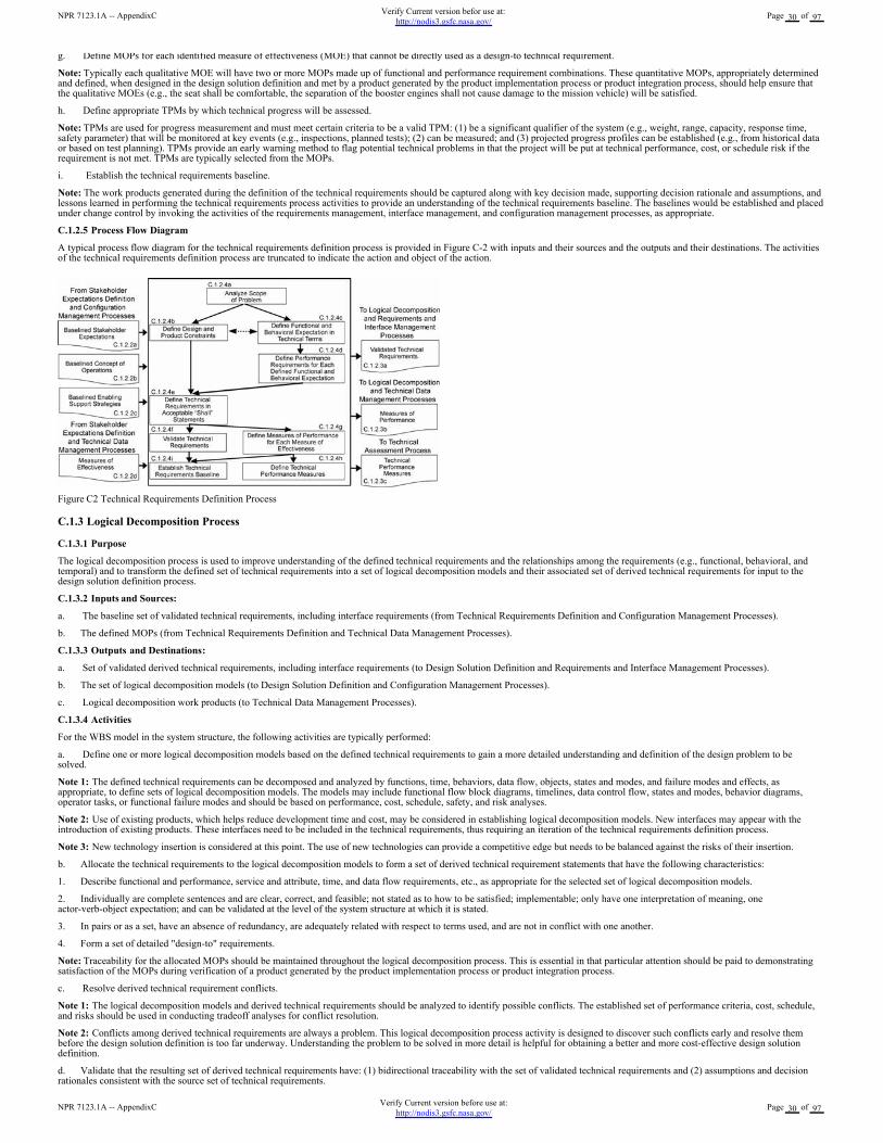
g. Define MOPs for each identified measure of effectiveness (MOE) that cannot be directly used as a design-to technical requirement.
Note: Typically each qualitative MOE will have two or more MOPs made up of functional and performance requirement combinations. These quantitative MOPs, appropriately determinedand defined, when designed in the design solution definition and met by a product generated by the product implementation process or product integration process, should help ensure thatthe qualitative MOEs (e.g., the seat shall be comfortable, the separation of the booster engines shall not cause damage to the mission vehicle) will be satisfied.
h. Define appropriate TPMs by which technical progress will be assessed.
Note: TPMs are used for progress measurement and must meet certain criteria to be a valid TPM: (1) be a significant qualifier of the system (e.g., weight, range, capacity, response time,safety parameter) that will be monitored at key events (e.g., inspections, planned tests); (2) can be measured; and (3) projected progress profiles can be established (e.g., from historical dataor based on test planning). TPMs provide an early warning method to flag potential technical problems in that the project will be put at technical performance, cost, or schedule risk if therequirement is not met. TPMs are typically selected from the MOPs.
i. Establish the technical requirements baseline.
Note: The work products generated during the definition of the technical requirements should be captured along with key decision made, supporting decision rationale and assumptions, andlessons learned in performing the technical requirements process activities to provide an understanding of the technical requirements baseline. The baselines would be established and placedunder change control by invoking the activities of the requirements management, interface management, and configuration management processes, as appropriate.
C.1.2.5 Process Flow Diagram
A typical process flow diagram for the technical requirements definition process is provided in Figure C-2 with inputs and their sources and the outputs and their destinations. The activitiesof the technical requirements definition process are truncated to indicate the action and object of the action.
Figure C2 Technical Requirements Definition Process
C.1.3 Logical Decomposition Process
C.1.3.1 Purpose
The logical decomposition process is used to improve understanding of the defined technical requirements and the relationships among the requirements (e.g., functional, behavioral, andtemporal) and to transform the defined set of technical requirements into a set of logical decomposition models and their associated set of derived technical requirements for input to thedesign solution definition process.
C.1.3.2 Inputs and Sources:
a. The baseline set of validated technical requirements, including interface requirements (from Technical Requirements Definition and Configuration Management Processes).
b. The defined MOPs (from Technical Requirements Definition and Technical Data Management Processes).
C.1.3.3 Outputs and Destinations:
a. Set of validated derived technical requirements, including interface requirements (to Design Solution Definition and Requirements and Interface Management Processes).
b. The set of logical decomposition models (to Design Solution Definition and Configuration Management Processes).
c. Logical decomposition work products (to Technical Data Management Processes).
C.1.3.4 Activities
For the WBS model in the system structure, the following activities are typically performed:
a. Define one or more logical decomposition models based on the defined technical requirements to gain a more detailed understanding and definition of the design problem to besolved.
Note 1: The defined technical requirements can be decomposed and analyzed by functions, time, behaviors, data flow, objects, states and modes, and failure modes and effects, asappropriate, to define sets of logical decomposition models. The models may include functional flow block diagrams, timelines, data control flow, states and modes, behavior diagrams,operator tasks, or functional failure modes and should be based on performance, cost, schedule, safety, and risk analyses.
Note 2: Use of existing products, which helps reduce development time and cost, may be considered in establishing logical decomposition models. New interfaces may appear with theintroduction of existing products. These interfaces need to be included in the technical requirements, thus requiring an iteration of the technical requirements definition process.
Note 3: New technology insertion is considered at this point. The use of new technologies can provide a competitive edge but needs to be balanced against the risks of their insertion.
b. Allocate the technical requirements to the logical decomposition models to form a set of derived technical requirement statements that have the following characteristics:
1. Describe functional and performance, service and attribute, time, and data flow requirements, etc., as appropriate for the selected set of logical decomposition models.
2. Individually are complete sentences and are clear, correct, and feasible; not stated as to how to be satisfied; implementable; only have one interpretation of meaning, oneactor-verb-object expectation; and can be validated at the level of the system structure at which it is stated.
3. In pairs or as a set, have an absence of redundancy, are adequately related with respect to terms used, and are not in conflict with one another.
4. Form a set of detailed "design-to" requirements.
Note: Traceability for the allocated MOPs should be maintained throughout the logical decomposition process. This is essential in that particular attention should be paid to demonstratingsatisfaction of the MOPs during verification of a product generated by the product implementation process or product integration process.
c. Resolve derived technical requirement conflicts.
Note 1: The logical decomposition models and derived technical requirements should be analyzed to identify possible conflicts. The established set of performance criteria, cost, schedule,and risks should be used in conducting tradeoff analyses for conflict resolution.
Note 2: Conflicts among derived technical requirements are always a problem. This logical decomposition process activity is designed to discover such conflicts early and resolve thembefore the design solution definition is too far underway. Understanding the problem to be solved in more detail is helpful for obtaining a better and more cost-effective design solutiondefinition.
d. Validate that the resulting set of derived technical requirements have: (1) bidirectional traceability with the set of validated technical requirements and (2) assumptions and decisionrationales consistent with the source set of technical requirements.
NPR 7123.1A -- AppendixCVerify Current version before use at:
http://nodis3.gsfc.nasa.gov/Page 30 of 97
NPR 7123.1A -- AppendixCVerify Current version befor use at:
http://nodis3.gsfc.nasa.gov/Page 30 of 97
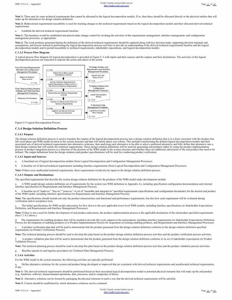
Note 1: There may be some technical requirements that cannot be allocated to the logical decomposition models. If so, then these should be allocated directly to the physical entities that willmake up the alternatives for design solution definition.
Note 2: Bidirectional requirements traceability is used for tracking changes to the technical requirements based on the logical decomposition models and their allocated derived technicalrequirements.
e. Establish the derived technical requirements baseline.
Note 1: The baselines would be established and placed under change control by invoking the activities of the requirements management, interface management, and configurationmanagement processes, as appropriate.
Note 2: The work products generated during the definition of the derived technical requirements should be captured along with key decision made, supporting decision rationale andassumptions, and lessons learned in performing the logical decomposition process activities to provide an understanding of the derived technical requirements baseline and the logicaldecomposition models and to permit traceability to technical requirements, stakeholder expectations, and logical decomposition models.
C.1.3.5 Process Flow Diagram
A typical process flow diagram for logical decomposition is provided in Figure C-3 with inputs and their sources and the outputs and their destinations. The activities of the logicaldecomposition process are truncated to indicate the action and object of the action.
Figure C3 Logical Decomposition Process
C.1.4 Design Solution Definition Process
C.1.4.1 Purpose
The design solution definition process is used to translate the outputs of the logical decomposition process into a design solution definition that is in a form consistent with the product-linelife-cycle phase and WBS model location in the system structure and that will satisfy phase exit criteria. This includes transforming the defined logical decomposition models and theirassociated sets of derived technical requirements into alternative solutions, then analyzing each alternative to be able to select a preferred alternative and fully define that alternative into afinal design solution that will satisfy the technical requirements. These design solution definitions will be used for generating end products either by using the product implementationprocess or product integration process as a function of the position of the WBS model in the system structure and whether there are additional subsystems of the end product that need to bedefined. The output definitions from the design solution (end product specifications) will be used for conducting product verification.
C.1.4.2 Inputs and Sources:
a. A baselined set of logical decomposition models (from Logical Decomposition and Configuration Management Processes).
b. A baseline set of derived technical requirements including interface requirements (from Logical Decomposition and Configuration Management Processes).
Note: If there were unallocated technical requirements, these requirements would also be inputs to the design solution definition process.
C.1.4.3 Outputs and Destinations:
The specified requirements that describe the system design solution definition for the products of the WBS model under development include:
a. A WBS model design solution definition set of requirements for the system (see WBS definition in Appendix A), including specification configuration documentation and externalinterface specification (to Requirements and Interface Management Process).
b. A baseline set of "make-to," "buy-to," "reuse-to," or set of "assemble and integrate-to" specified requirements (specifications and configuration documents) for the desired end productof the WBS model, including interface specifications (to Requirements and Interface Management Process).
Note: The specifications should include not only the product characteristics and functional and performance requirements, but also how each requirement will be evaluated duringverification and/or acceptance tests.
c. The initial specifications for WBS model subsystems for flow down to the next applicable lower level WBS models, including interface specifications (to Stakeholder ExpectationsDefinition, and Requirements and Interface Management Processes).
Note: If there is not a need for further development of end product subsystems, the product implementation process is the applicable destination of the end product specified requirements.(See C.1.4.2 above.)
d. The requirements for enabling products that will be needed to provide life-cycle support to the end products, including interface requirements (to Stakeholder Expectations DefinitionProcess for development of enabling products or to Product Implementation Process for acquisition of existing enabling products, and Requirements and Interface Management Processes).
e. A product verification plan that will be used to demonstrate that the product generated from the design solution definition conforms to the design solution definition specifiedrequirements (to Product Verification Process).
Note: The technical planning process should be used to develop this plan based on the product design solution definition process activities and the product verification process activities.
f. A product validation plan that will be used to demonstrate that the product generated from the design solution definition conforms to its set of stakeholder expectations (to ProductValidation Process).
Note: The technical planning process should be used to develop this plan based on the product design solution definition process activities and the product validation process activities.
g. Baseline operate-to and logistics procedures (to Technical Data Management Process).
C.1.4.4 Activities
For the WBS model in the system structure, the following activities are typically performed:
a. Define alternative solutions for the system end product being developed or improved that are consistent with derived technical requirements and nonallocated technical requirements,if any.
Note 1: The derived technical requirements should be partitioned based on their associated logical decomposition model to potential physical elements that will make up the end product(e.g., hardware, software, human/manual operations, data, processes, and/or composites of these).
Note 2: Alternative solutions can be formed by packaging the physical elements in such a way that the derived technical requirements will be satisfied.
Note 3: Criteria should be established by which alternative solutions can be evaluated.
NPR 7123.1A -- AppendixCVerify Current version before use at:
http://nodis3.gsfc.nasa.gov/Page 31 of 97
NPR 7123.1A -- AppendixCVerify Current version befor use at:
http://nodis3.gsfc.nasa.gov/Page 31 of 97
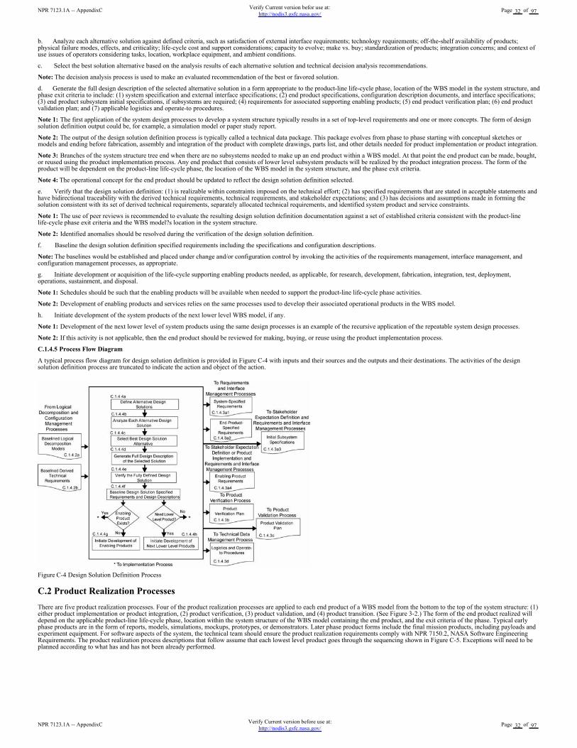
b. Analyze each alternative solution against defined criteria, such as satisfaction of external interface requirements; technology requirements; off-the-shelf availability of products;physical failure modes, effects, and criticality; life-cycle cost and support considerations; capacity to evolve; make vs. buy; standardization of products; integration concerns; and context ofuse issues of operators considering tasks, location, workplace equipment, and ambient conditions.
c. Select the best solution alternative based on the analysis results of each alternative solution and technical decision analysis recommendations.
Note: The decision analysis process is used to make an evaluated recommendation of the best or favored solution.
d. Generate the full design description of the selected alternative solution in a form appropriate to the product-line life-cycle phase, location of the WBS model in the system structure, andphase exit criteria to include: (1) system specification and external interface specifications; (2) end product specifications, configuration description documents, and interface specifications;(3) end product subsystem initial specifications, if subsystems are required; (4) requirements for associated supporting enabling products; (5) end product verification plan; (6) end productvalidation plan; and (7) applicable logistics and operate-to procedures.
Note 1: The first application of the system design processes to develop a system structure typically results in a set of top-level requirements and one or more concepts. The form of designsolution definition output could be, for example, a simulation model or paper study report.
Note 2: The output of the design solution definition process is typically called a technical data package. This package evolves from phase to phase starting with conceptual sketches ormodels and ending before fabrication, assembly and integration of the product with complete drawings, parts list, and other details needed for product implementation or product integration.
Note 3: Branches of the system structure tree end when there are no subsystems needed to make up an end product within a WBS model. At that point the end product can be made, bought,or reused using the product implementation process. Any end product that consists of lower level subsystem products will be realized by the product integration process. The form of theproduct will be dependent on the product-line life-cycle phase, the location of the WBS model in the system structure, and the phase exit criteria.
Note 4: The operational concept for the end product should be updated to reflect the design solution definition selected.
e. Verify that the design solution definition: (1) is realizable within constraints imposed on the technical effort; (2) has specified requirements that are stated in acceptable statements andhave bidirectional traceability with the derived technical requirements, technical requirements, and stakeholder expectations; and (3) has decisions and assumptions made in forming thesolution consistent with its set of derived technical requirements, separately allocated technical requirements, and identified system product and service constraints.
Note 1: The use of peer reviews is recommended to evaluate the resulting design solution definition documentation against a set of established criteria consistent with the product-linelife-cycle phase exit criteria and the WBS model?s location in the system structure.
Note 2: Identified anomalies should be resolved during the verification of the design solution definition.
f. Baseline the design solution definition specified requirements including the specifications and configuration descriptions.
Note: The baselines would be established and placed under change and/or configuration control by invoking the activities of the requirements management, interface management, andconfiguration management processes, as appropriate.
g. Initiate development or acquisition of the life-cycle supporting enabling products needed, as applicable, for research, development, fabrication, integration, test, deployment,operations, sustainment, and disposal.
Note 1: Schedules should be such that the enabling products will be available when needed to support the product-line life-cycle phase activities.
Note 2: Development of enabling products and services relies on the same processes used to develop their associated operational products in the WBS model.
h. Initiate development of the system products of the next lower level WBS model, if any.
Note 1: Development of the next lower level of system products using the same design processes is an example of the recursive application of the repeatable system design processes.
Note 2: If this activity is not applicable, then the end product should be reviewed for making, buying, or reuse using the product implementation process.
C.1.4.5 Process Flow Diagram
A typical process flow diagram for design solution definition is provided in Figure C-4 with inputs and their sources and the outputs and their destinations. The activities of the designsolution definition process are truncated to indicate the action and object of the action.
Figure C-4 Design Solution Definition Process
C.2 Product Realization Processes
There are five product realization processes. Four of the product realization processes are applied to each end product of a WBS model from the bottom to the top of the system structure: (1)either product implementation or product integration, (2) product verification, (3) product validation, and (4) product transition. (See Figure 3-2.) The form of the end product realized willdepend on the applicable product-line life-cycle phase, location within the system structure of the WBS model containing the end product, and the exit criteria of the phase. Typical earlyphase products are in the form of reports, models, simulations, mockups, prototypes, or demonstrators. Later phase product forms include the final mission products, including payloads andexperiment equipment. For software aspects of the system, the technical team should ensure the product realization requirements comply with NPR 7150.2, NASA Software EngineeringRequirements. The product realization process descriptions that follow assume that each lowest level product goes through the sequencing shown in Figure C-5. Exceptions will need to beplanned according to what has and has not been already performed.
NPR 7123.1A -- AppendixCVerify Current version before use at:
http://nodis3.gsfc.nasa.gov/Page 32 of 97
NPR 7123.1A -- AppendixCVerify Current version befor use at:
http://nodis3.gsfc.nasa.gov/Page 32 of 97
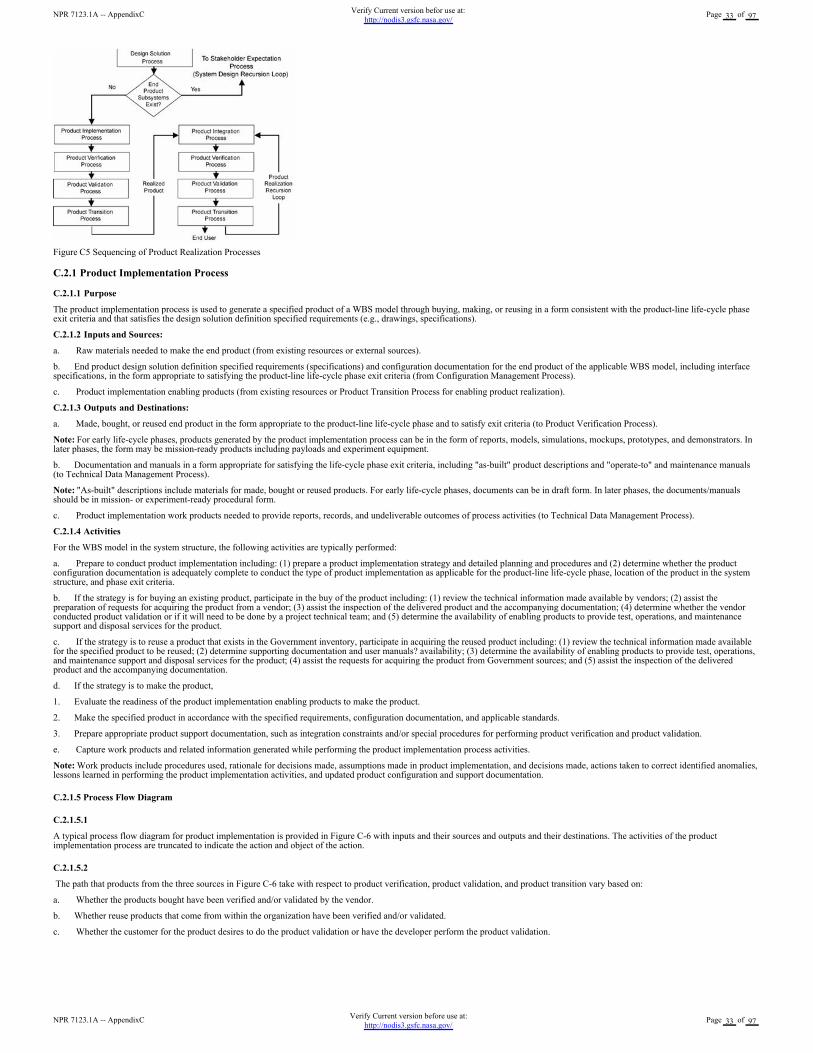
Figure C5 Sequencing of Product Realization Processes
C.2.1 Product Implementation Process
C.2.1.1 Purpose
The product implementation process is used to generate a specified product of a WBS model through buying, making, or reusing in a form consistent with the product-line life-cycle phaseexit criteria and that satisfies the design solution definition specified requirements (e.g., drawings, specifications).
C.2.1.2 Inputs and Sources:
a. Raw materials needed to make the end product (from existing resources or external sources).
b. End product design solution definition specified requirements (specifications) and configuration documentation for the end product of the applicable WBS model, including interfacespecifications, in the form appropriate to satisfying the product-line life-cycle phase exit criteria (from Configuration Management Process).
c. Product implementation enabling products (from existing resources or Product Transition Process for enabling product realization).
C.2.1.3 Outputs and Destinations:
a. Made, bought, or reused end product in the form appropriate to the product-line life-cycle phase and to satisfy exit criteria (to Product Verification Process).
Note: For early life-cycle phases, products generated by the product implementation process can be in the form of reports, models, simulations, mockups, prototypes, and demonstrators. Inlater phases, the form may be mission-ready products including payloads and experiment equipment.
b. Documentation and manuals in a form appropriate for satisfying the life-cycle phase exit criteria, including "as-built" product descriptions and "operate-to" and maintenance manuals(to Technical Data Management Process).
Note: "As-built" descriptions include materials for made, bought or reused products. For early life-cycle phases, documents can be in draft form. In later phases, the documents/manualsshould be in mission- or experiment-ready procedural form.
c. Product implementation work products needed to provide reports, records, and undeliverable outcomes of process activities (to Technical Data Management Process).
C.2.1.4 Activities
For the WBS model in the system structure, the following activities are typically performed:
a. Prepare to conduct product implementation including: (1) prepare a product implementation strategy and detailed planning and procedures and (2) determine whether the productconfiguration documentation is adequately complete to conduct the type of product implementation as applicable for the product-line life-cycle phase, location of the product in the systemstructure, and phase exit criteria.
b. If the strategy is for buying an existing product, participate in the buy of the product including: (1) review the technical information made available by vendors; (2) assist thepreparation of requests for acquiring the product from a vendor; (3) assist the inspection of the delivered product and the accompanying documentation; (4) determine whether the vendorconducted product validation or if it will need to be done by a project technical team; and (5) determine the availability of enabling products to provide test, operations, and maintenancesupport and disposal services for the product.
c. If the strategy is to reuse a product that exists in the Government inventory, participate in acquiring the reused product including: (1) review the technical information made availablefor the specified product to be reused; (2) determine supporting documentation and user manuals? availability; (3) determine the availability of enabling products to provide test, operations,and maintenance support and disposal services for the product; (4) assist the requests for acquiring the product from Government sources; and (5) assist the inspection of the deliveredproduct and the accompanying documentation.
d. If the strategy is to make the product,
1. Evaluate the readiness of the product implementation enabling products to make the product.
2. Make the specified product in accordance with the specified requirements, configuration documentation, and applicable standards.
3. Prepare appropriate product support documentation, such as integration constraints and/or special procedures for performing product verification and product validation.
e. Capture work products and related information generated while performing the product implementation process activities.
Note: Work products include procedures used, rationale for decisions made, assumptions made in product implementation, and decisions made, actions taken to correct identified anomalies,lessons learned in performing the product implementation activities, and updated product configuration and support documentation.
C.2.1.5 Process Flow Diagram
C.2.1.5.1
A typical process flow diagram for product implementation is provided in Figure C-6 with inputs and their sources and outputs and their destinations. The activities of the productimplementation process are truncated to indicate the action and object of the action.
C.2.1.5.2
The path that products from the three sources in Figure C-6 take with respect to product verification, product validation, and product transition vary based on:
a. Whether the products bought have been verified and/or validated by the vendor.
b. Whether reuse products that come from within the organization have been verified and/or validated.
c. Whether the customer for the product desires to do the product validation or have the developer perform the product validation.
NPR 7123.1A -- AppendixCVerify Current version before use at:
http://nodis3.gsfc.nasa.gov/Page 33 of 97
NPR 7123.1A -- AppendixCVerify Current version befor use at:
http://nodis3.gsfc.nasa.gov/Page 33 of 97
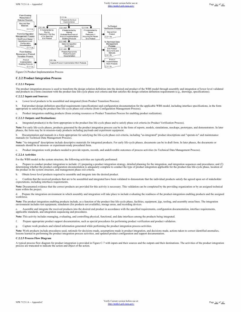
Figure C6 Product Implementation Process
C.2.2 Product Integration Process
C.2.2.1 Purpose
The product integration process is used to transform the design solution definition into the desired end product of the WBS model through assembly and integration of lower level validatedend products in a form consistent with the product-line life-cycle phase exit criteria and that satisfies the design solution definition requirements (e.g., drawings, specifications).
C.2.2.2 Inputs and Sources:
a. Lower level products to be assembled and integrated (from Product Transition Process).
b. End product design definition specified requirements (specifications) and configuration documentation for the applicable WBS model, including interface specifications, in the formappropriate to satisfying the product-line life-cycle phase exit criteria (from Configuration Management Process).
c. Product integration enabling products (from existing resources or Product Transition Process for enabling product realization).
C.2.2.3 Outputs and Destinations:
a. Integrated product(s) in the form appropriate to the product-line life-cycle phase and to satisfy phase exit criteria (to Product Verification Process).
Note: For early life-cycle phases, products generated by the product integration process can be in the form of reports, models, simulations, mockups, prototypes, and demonstrators. In laterphases, the form may be in mission-ready products including payloads and experiment equipment.
b. Documentation and manuals in a form appropriate for satisfying the life-cycle phase exit criteria, including "as-integrated" product descriptions and "operate-to" and maintenancemanuals (to Technical Data Management Process).
Note: "As-integrated" descriptions include descriptive materials for integrated products. For early life-cycle phases, documents can be in draft form. In later phases, the documents ormanuals should be in mission- or experiment-ready procedural form.
c. Product integration work products needed to provide reports, records, and undeliverable outcomes of process activities (to Technical Data Management Process).
C.2.2.4 Activities
For the WBS model in the system structure, the following activities are typically performed:
a. Prepare to conduct product integration to include: (1) preparing a product integration strategy, detailed planning for the integration, and integration sequences and procedures; and (2)determining whether the product configuration documentation is adequately complete to conduct the type of product integration applicable for the product-line life-cycle phase, location ofthe product in the system structure, and management phase exit criteria.
b. Obtain lower level products required to assemble and integrate into the desired product.
c. Confirm that the received products that are to be assembled and integrated have been validated to demonstrate that the individual products satisfy the agreed upon set of stakeholderexpectations, including interfaces requirements.
Note: Documented evidence that the correct products are provided for this activity is necessary. This validation can be completed by the providing organization or by an assigned technicalteam within the project.
d. Prepare the integration environment in which assembly and integration will take place to include evaluating the readiness of the product-integration enabling products and the assignedworkforce.
Note: The product integration enabling products include, as a function of the product-line life-cycle phase, facilities, equipment, jigs, tooling, and assembly areas/lines. The integrationenvironment includes test equipment, simulators (for products not available), storage areas, and recording devices.
e. Assemble and integrate the received products into the desired end product in accordance with the specified requirements, configuration documentation, interface requirements,applicable standards, and integration sequencing and procedures.
Note: This activity includes managing, evaluating, and controlling physical, functional, and data interfaces among the products being integrated.
f. Prepare appropriate product support documentation, such as special procedures for performing product verification and product validation.
g. Capture work products and related information generated while performing the product integration process activities.
Note: Work products include procedures used, rationale for decisions made, assumptions made in product integration, and decisions made, actions taken to correct identified anomalies,lessons learned in performing the product integration process activities, and updated product configuration and support documentation.
C.2.2.5 Process Flow Diagram
A typical process flow diagram for product integration is provided in Figure C-7 with inputs and their sources and the outputs and their destinations. The activities of the product integrationprocess are truncated to indicate the action and object of the action.
NPR 7123.1A -- AppendixCVerify Current version before use at:
http://nodis3.gsfc.nasa.gov/Page 34 of 97
NPR 7123.1A -- AppendixCVerify Current version befor use at:
http://nodis3.gsfc.nasa.gov/Page 34 of 97
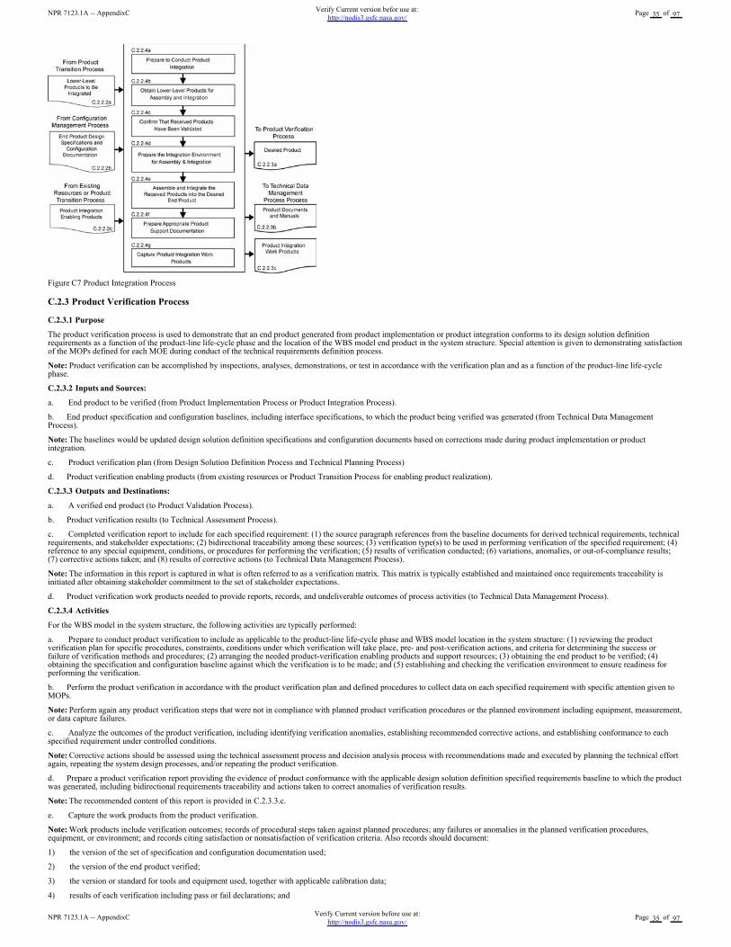
Figure C7 Product Integration Process
C.2.3 Product Verification Process
C.2.3.1 Purpose
The product verification process is used to demonstrate that an end product generated from product implementation or product integration conforms to its design solution definitionrequirements as a function of the product-line life-cycle phase and the location of the WBS model end product in the system structure. Special attention is given to demonstrating satisfactionof the MOPs defined for each MOE during conduct of the technical requirements definition process.
Note: Product verification can be accomplished by inspections, analyses, demonstrations, or test in accordance with the verification plan and as a function of the product-line life-cyclephase.
C.2.3.2 Inputs and Sources:
a. End product to be verified (from Product Implementation Process or Product Integration Process).
b. End product specification and configuration baselines, including interface specifications, to which the product being verified was generated (from Technical Data ManagementProcess).
Note: The baselines would be updated design solution definition specifications and configuration documents based on corrections made during product implementation or productintegration.
c. Product verification plan (from Design Solution Definition Process and Technical Planning Process)
d. Product verification enabling products (from existing resources or Product Transition Process for enabling product realization).
C.2.3.3 Outputs and Destinations:
a. A verified end product (to Product Validation Process).
b. Product verification results (to Technical Assessment Process).
c. Completed verification report to include for each specified requirement: (1) the source paragraph references from the baseline documents for derived technical requirements, technicalrequirements, and stakeholder expectations; (2) bidirectional traceability among these sources; (3) verification type(s) to be used in performing verification of the specified requirement; (4)reference to any special equipment, conditions, or procedures for performing the verification; (5) results of verification conducted; (6) variations, anomalies, or out-of-compliance results;(7) corrective actions taken; and (8) results of corrective actions (to Technical Data Management Process).
Note: The information in this report is captured in what is often referred to as a verification matrix. This matrix is typically established and maintained once requirements traceability isinitiated after obtaining stakeholder commitment to the set of stakeholder expectations.
d. Product verification work products needed to provide reports, records, and undeliverable outcomes of process activities (to Technical Data Management Process).
C.2.3.4 Activities
For the WBS model in the system structure, the following activities are typically performed:
a. Prepare to conduct product verification to include as applicable to the product-line life-cycle phase and WBS model location in the system structure: (1) reviewing the productverification plan for specific procedures, constraints, conditions under which verification will take place, pre- and post-verification actions, and criteria for determining the success orfailure of verification methods and procedures; (2) arranging the needed product-verification enabling products and support resources; (3) obtaining the end product to be verified; (4)obtaining the specification and configuration baseline against which the verification is to be made; and (5) establishing and checking the verification environment to ensure readiness forperforming the verification.
b. Perform the product verification in accordance with the product verification plan and defined procedures to collect data on each specified requirement with specific attention given toMOPs.
Note: Perform again any product verification steps that were not in compliance with planned product verification procedures or the planned environment including equipment, measurement,or data capture failures.
c. Analyze the outcomes of the product verification, including identifying verification anomalies, establishing recommended corrective actions, and establishing conformance to eachspecified requirement under controlled conditions.
Note: Corrective actions should be assessed using the technical assessment process and decision analysis process with recommendations made and executed by planning the technical effortagain, repeating the system design processes, and/or repeating the product verification.
d. Prepare a product verification report providing the evidence of product conformance with the applicable design solution definition specified requirements baseline to which the productwas generated, including bidirectional requirements traceability and actions taken to correct anomalies of verification results.
Note: The recommended content of this report is provided in C.2.3.3.c.
e. Capture the work products from the product verification.
Note: Work products include verification outcomes; records of procedural steps taken against planned procedures; any failures or anomalies in the planned verification procedures,equipment, or environment; and records citing satisfaction or nonsatisfaction of verification criteria. Also records should document:
1) the version of the set of specification and configuration documentation used;
2) the version of the end product verified;
3) the version or standard for tools and equipment used, together with applicable calibration data;
4) results of each verification including pass or fail declarations; and
NPR 7123.1A -- AppendixCVerify Current version before use at:
http://nodis3.gsfc.nasa.gov/Page 35 of 97
NPR 7123.1A -- AppendixCVerify Current version befor use at:
http://nodis3.gsfc.nasa.gov/Page 35 of 97
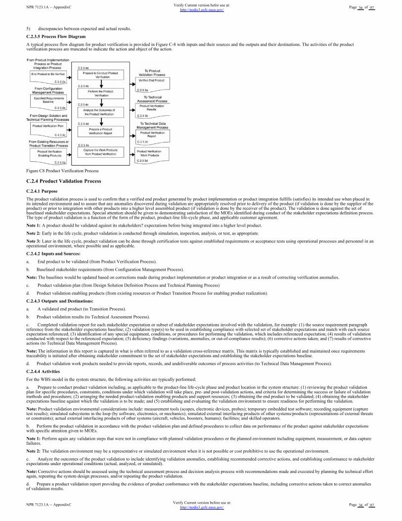
5) discrepancies between expected and actual results.
C.2.3.5 Process Flow Diagram
A typical process flow diagram for product verification is provided in Figure C-8 with inputs and their sources and the outputs and their destinations. The activities of the productverification process are truncated to indicate the action and object of the action.
Figure C8 Product Verification Process
C.2.4 Product Validation Process
C.2.4.1 Purpose
The product validation process is used to confirm that a verified end product generated by product implementation or product integration fulfills (satisfies) its intended use when placed inits intended environment and to assure that any anomalies discovered during validation are appropriately resolved prior to delivery of the product (if validation is done by the supplier of theproduct) or prior to integration with other products into a higher level assembled product (if validation is done by the receiver of the product). The validation is done against the set ofbaselined stakeholder expectations. Special attention should be given to demonstrating satisfaction of the MOEs identified during conduct of the stakeholder expectations definition process.The type of product validation is a function of the form of the product, product-line life-cycle phase, and applicable customer agreement.
Note 1: A product should be validated against its stakeholders? expectations before being integrated into a higher level product.
Note 2: Early in the life cycle, product validation is conducted through simulation, inspection, analysis, or test, as appropriate.
Note 3: Later in the life cycle, product validation can be done through certification tests against established requirements or acceptance tests using operational processes and personnel in anoperational environment, where possible and as applicable.
C.2.4.2 Inputs and Sources:
a. End product to be validated (from Product Verification Process).
b. Baselined stakeholder requirements (from Configuration Management Process).
Note: The baselines would be updated based on corrections made during product implementation or product integration or as a result of correcting verification anomalies.
c. Product validation plan (from Design Solution Definition Process and Technical Planning Process)
d. Product validation enabling products (from existing resources or Product Transition Process for enabling product realization).
C.2.4.3 Outputs and Destinations:
a. A validated end product (to Transition Process).
b. Product validation results (to Technical Assessment Process).
c. Completed validation report for each stakeholder expectation or subset of stakeholder expectations involved with the validation, for example: (1) the source requirement paragraphreference from the stakeholder expectations baseline; (2) validation type(s) to be used in establishing compliance with selected set of stakeholder expectations and match with each sourceexpectation referenced; (3) identification of any special equipment, conditions, or procedures for performing the validation, which includes referenced expectation; (4) results of validationconducted with respect to the referenced expectation; (5) deficiency findings (variations, anomalies, or out-of-compliance results); (6) corrective actions taken; and (7) results of correctiveactions (to Technical Data Management Process).
Note: The information in this report is captured in what is often referred to as a validation cross-reference matrix. This matrix is typically established and maintained once requirementstraceability is initiated after obtaining stakeholder commitment to the set of stakeholder expectations and establishing the stakeholder expectations baseline.
d. Product validation work products needed to provide reports, records, and undeliverable outcomes of process activities (to Technical Data Management Process).
C.2.4.4 Activities
For the WBS model in the system structure, the following activities are typically performed:
a. Prepare to conduct product validation including, as applicable to the product-line life-cycle phase and product location in the system structure: (1) reviewing the product validationplan for specific procedures, constraints, conditions under which validation will take place, pre- and post-validation actions, and criteria for determining the success or failure of validationmethods and procedures; (2) arranging the needed product-validation enabling products and support resources; (3) obtaining the end product to be validated; (4) obtaining the stakeholderexpectations baseline against which the validation is to be made; and (5) establishing and evaluating the validation environment to ensure readiness for performing the validation.
Note: Product validation environmental considerations include: measurement tools (scopes, electronic devices, probes); temporary embedded test software; recording equipment (capturetest results); simulated subsystems in the loop (by software, electronics, or mechanics); simulated external interfacing products of other systems/products (representations of external threatsor constraints); actual external interfacing products of other systems (aircraft, vehicles, boosters, humans); facilities; and skilled operators.
b. Perform the product validation in accordance with the product validation plan and defined procedures to collect data on performance of the product against stakeholder expectationswith specific attention given to MOEs.
Note 1: Perform again any validation steps that were not in compliance with planned validation procedures or the planned environment including equipment, measurement, or data capturefailures.
Note 2: The validation environment may be a representative or simulated environment when it is not possible or cost prohibitive to use the operational environment.
c. Analyze the outcomes of the product validation to include identifying validation anomalies, establishing recommended corrective actions, and establishing conformance to stakeholderexpectations under operational conditions (actual, analyzed, or simulated).
Note: Corrective actions should be assessed using the technical assessment process and decision analysis process with recommendations made and executed by planning the technical effortagain, repeating the system design processes, and/or repeating the product validation.
d. Prepare a product validation report providing the evidence of product conformance with the stakeholder expectations baseline, including corrective actions taken to correct anomaliesof validation results.
NPR 7123.1A -- AppendixCVerify Current version before use at:
http://nodis3.gsfc.nasa.gov/Page 36 of 97
NPR 7123.1A -- AppendixCVerify Current version befor use at:
http://nodis3.gsfc.nasa.gov/Page 36 of 97
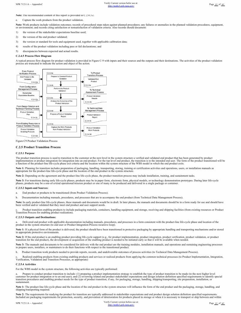
Note: The recommended content of this report is provided in C.2.4.3.c.
e. Capture the work products from the product validation.
Note: Work products include validation outcomes; records of procedural steps taken against planned procedures; any failures or anomalies in the planned validation procedures, equipment,or environment; and records citing satisfaction or nonsatisfaction of validation criteria. Also records should document:
1) the version of the stakeholder expectations baseline used;
2) the version of the end product validated;
3) the version or standard for tools and equipment used, together with applicable calibration data;
4) results of the product validation including pass or fail declarations; and
5) discrepancies between expected and actual results.
C.2.4.5 Process Flow Diagram
A typical process flow diagram for product validation is provided in Figure C-9 with inputs and their sources and the outputs and their destinations. The activities of the product validationprocess are truncated to indicate the action and object of the action.
Figure C9 Product Validation Process
C.2.5 Product Transition Process
C.2.5.1 Purpose
The product transition process is used to transition to the customer at the next level in the system structure a verified and validated end product that has been generated by productimplementation or product integration for integration into an end product. For the top level end product, the transition is to the intended end user. The form of the product transitioned will bea function of the product-line life-cycle phase exit criteria and the location within the system structure of the WBS model in which the end product exits.
Note 1: Planning for transition includes preparation of packaging, handling, transporting, storing, training or certification activities and operations, users, or installation manuals asappropriate for the product-line life-cycle phase and the location of the end product in the system structure.
Note 2: Depending on the agreement and the product-line life-cycle phase, the product transition process may include installation, training, and sustainment tasks.
Note 3: For transitions during early life-cycle phases, products may be in paper form, electronic form, physical models, or technology demonstration prototypes. During later life-cyclephases, products may be a one-of-a-kind operational/mission product or one of many to be produced and delivered in a single package or container.
C.2.5.2 Inputs and Sources:
a. End product or products to be transitioned (from Product Validation Process).
b. Documentation including manuals, procedures, and processes that are to accompany the end product (from Technical Data Management Process).
Note: In early product-line life-cycle phases, these manuals and documents would be in draft. In later phases, the manuals and documents should be in a form ready for use and should havebeen verified and/or validated that they meet end product and user support needs.
c. Product transition enabling products to include packaging materials, containers, handling equipment, and storage, receiving and shipping facilities (from existing resources or ProductTransition Process for enabling product realization).
C.2.5.3 Outputs and Destinations:
a. Delivered end product with applicable documentation including manuals, procedures, and processes in a form consistent with the product-line life-cycle phase and location of theproduct in the system structure (to end user or Product Integration Process recursive loop).
Note 1: If a physical form of the product is delivered, the product should have been transitioned in protective packaging by appropriate handling and transporting mechanisms and/or storedin appropriate protective environments.
Note 2: If the end product is an enabling product providing life-cycle support (e.g., for product implementation, product integration, product verification, product validation, or producttransition for the end product), the development or acquisition of the enabling product is needed to be initiated early so that it will be available when needed.
Note 3: The manuals and documents to be considered for delivery with the end product are the training modules, installation manuals, and operations and sustaining engineering processesto prepare users, installers, or maintainers to do their functions with respect to the transitioned product.
b. Product transition work products needed to provide reports, records, and undeliverable outcomes of process activities (to Technical Data Management Process).
c. Realized enabling products from existing enabling products and services or realized products from applying the common technical processes (to Product Implementation, Integration,Verification, Validation and Transition Processes, as appropriate)
C.2.5.4 Activities
For the WBS model in the system structure, the following activities are typically performed:
a. Prepare to conduct product transition to include: (1) preparing a product implementation strategy to establish the type of product transition to be made (to the next higher levelcustomer for product integration or to an end user); and (2) reviewing related end product stakeholder expectations and design solution definition specified requirements to identify specialtransition procedures and enabling product needs for the type of product transition, if any, for packaging, storage, handling, shipping/transporting, site preparation, installation, orsustainment.
Note 1: The product-line life-cycle phase and the location of the end product in the system structure will influence the form of the end product and the packaging, storage, handling, andshipping/transporting required.
Note 2: The requirements for readying the product for transition are typically addressed in stakeholder expectations and end product design solution definition specified requirements.Included are packaging requirements for protection, security, and prevention of deterioration for products placed in storage or when it is necessary to transport or ship between and within
NPR 7123.1A -- AppendixCVerify Current version before use at:
http://nodis3.gsfc.nasa.gov/Page 37 of 97
NPR 7123.1A -- AppendixCVerify Current version befor use at:
http://nodis3.gsfc.nasa.gov/Page 37 of 97
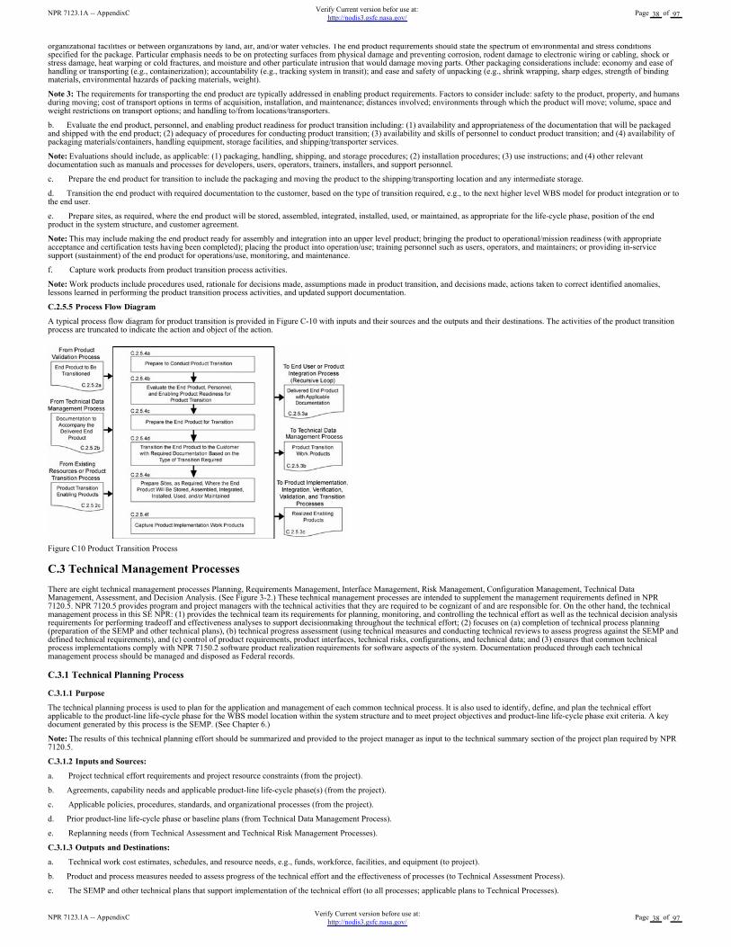
organizational facilities or between organizations by land, air, and/or water vehicles. The end product requirements should state the spectrum of environmental and stress conditionsspecified for the package. Particular emphasis needs to be on protecting surfaces from physical damage and preventing corrosion, rodent damage to electronic wiring or cabling, shock orstress damage, heat warping or cold fractures, and moisture and other particulate intrusion that would damage moving parts. Other packaging considerations include: economy and ease ofhandling or transporting (e.g., containerization); accountability (e.g., tracking system in transit); and ease and safety of unpacking (e.g., shrink wrapping, sharp edges, strength of bindingmaterials, environmental hazards of packing materials, weight).
Note 3: The requirements for transporting the end product are typically addressed in enabling product requirements. Factors to consider include: safety to the product, property, and humansduring moving; cost of transport options in terms of acquisition, installation, and maintenance; distances involved; environments through which the product will move; volume, space andweight restrictions on transport options; and handling to/from locations/transporters.
b. Evaluate the end product, personnel, and enabling product readiness for product transition including: (1) availability and appropriateness of the documentation that will be packagedand shipped with the end product; (2) adequacy of procedures for conducting product transition; (3) availability and skills of personnel to conduct product transition; and (4) availability ofpackaging materials/containers, handling equipment, storage facilities, and shipping/transporter services.
Note: Evaluations should include, as applicable: (1) packaging, handling, shipping, and storage procedures; (2) installation procedures; (3) use instructions; and (4) other relevantdocumentation such as manuals and processes for developers, users, operators, trainers, installers, and support personnel.
c. Prepare the end product for transition to include the packaging and moving the product to the shipping/transporting location and any intermediate storage.
d. Transition the end product with required documentation to the customer, based on the type of transition required, e.g., to the next higher level WBS model for product integration or tothe end user.
e. Prepare sites, as required, where the end product will be stored, assembled, integrated, installed, used, or maintained, as appropriate for the life-cycle phase, position of the endproduct in the system structure, and customer agreement.
Note: This may include making the end product ready for assembly and integration into an upper level product; bringing the product to operational/mission readiness (with appropriateacceptance and certification tests having been completed); placing the product into operation/use; training personnel such as users, operators, and maintainers; or providing in-servicesupport (sustainment) of the end product for operations/use, monitoring, and maintenance.
f. Capture work products from product transition process activities.
Note: Work products include procedures used, rationale for decisions made, assumptions made in product transition, and decisions made, actions taken to correct identified anomalies,lessons learned in performing the product transition process activities, and updated support documentation.
C.2.5.5 Process Flow Diagram
A typical process flow diagram for product transition is provided in Figure C-10 with inputs and their sources and the outputs and their destinations. The activities of the product transitionprocess are truncated to indicate the action and object of the action.
Figure C10 Product Transition Process
C.3 Technical Management Processes
There are eight technical management processes Planning, Requirements Management, Interface Management, Risk Management, Configuration Management, Technical DataManagement, Assessment, and Decision Analysis. (See Figure 3-2.) These technical management processes are intended to supplement the management requirements defined in NPR7120.5. NPR 7120.5 provides program and project managers with the technical activities that they are required to be cognizant of and are responsible for. On the other hand, the technicalmanagement process in this SE NPR: (1) provides the technical team its requirements for planning, monitoring, and controlling the technical effort as well as the technical decision analysisrequirements for performing tradeoff and effectiveness analyses to support decisionmaking throughout the technical effort; (2) focuses on (a) completion of technical process planning(preparation of the SEMP and other technical plans), (b) technical progress assessment (using technical measures and conducting technical reviews to assess progress against the SEMP anddefined technical requirements), and (c) control of product requirements, product interfaces, technical risks, configurations, and technical data; and (3) ensures that common technicalprocess implementations comply with NPR 7150.2 software product realization requirements for software aspects of the system. Documentation produced through each technicalmanagement process should be managed and disposed as Federal records.
C.3.1 Technical Planning Process
C.3.1.1 Purpose
The technical planning process is used to plan for the application and management of each common technical process. It is also used to identify, define, and plan the technical effortapplicable to the product-line life-cycle phase for the WBS model location within the system structure and to meet project objectives and product-line life-cycle phase exit criteria. A keydocument generated by this process is the SEMP. (See Chapter 6.)
Note: The results of this technical planning effort should be summarized and provided to the project manager as input to the technical summary section of the project plan required by NPR7120.5.
C.3.1.2 Inputs and Sources:
a. Project technical effort requirements and project resource constraints (from the project).
b. Agreements, capability needs and applicable product-line life-cycle phase(s) (from the project).
c. Applicable policies, procedures, standards, and organizational processes (from the project).
d. Prior product-line life-cycle phase or baseline plans (from Technical Data Management Process).
e. Replanning needs (from Technical Assessment and Technical Risk Management Processes).
C.3.1.3 Outputs and Destinations:
a. Technical work cost estimates, schedules, and resource needs, e.g., funds, workforce, facilities, and equipment (to project).
b. Product and process measures needed to assess progress of the technical effort and the effectiveness of processes (to Technical Assessment Process).
c. The SEMP and other technical plans that support implementation of the technical effort (to all processes; applicable plans to Technical Processes).
NPR 7123.1A -- AppendixCVerify Current version before use at:
http://nodis3.gsfc.nasa.gov/Page 38 of 97
NPR 7123.1A -- AppendixCVerify Current version befor use at:
http://nodis3.gsfc.nasa.gov/Page 38 of 97
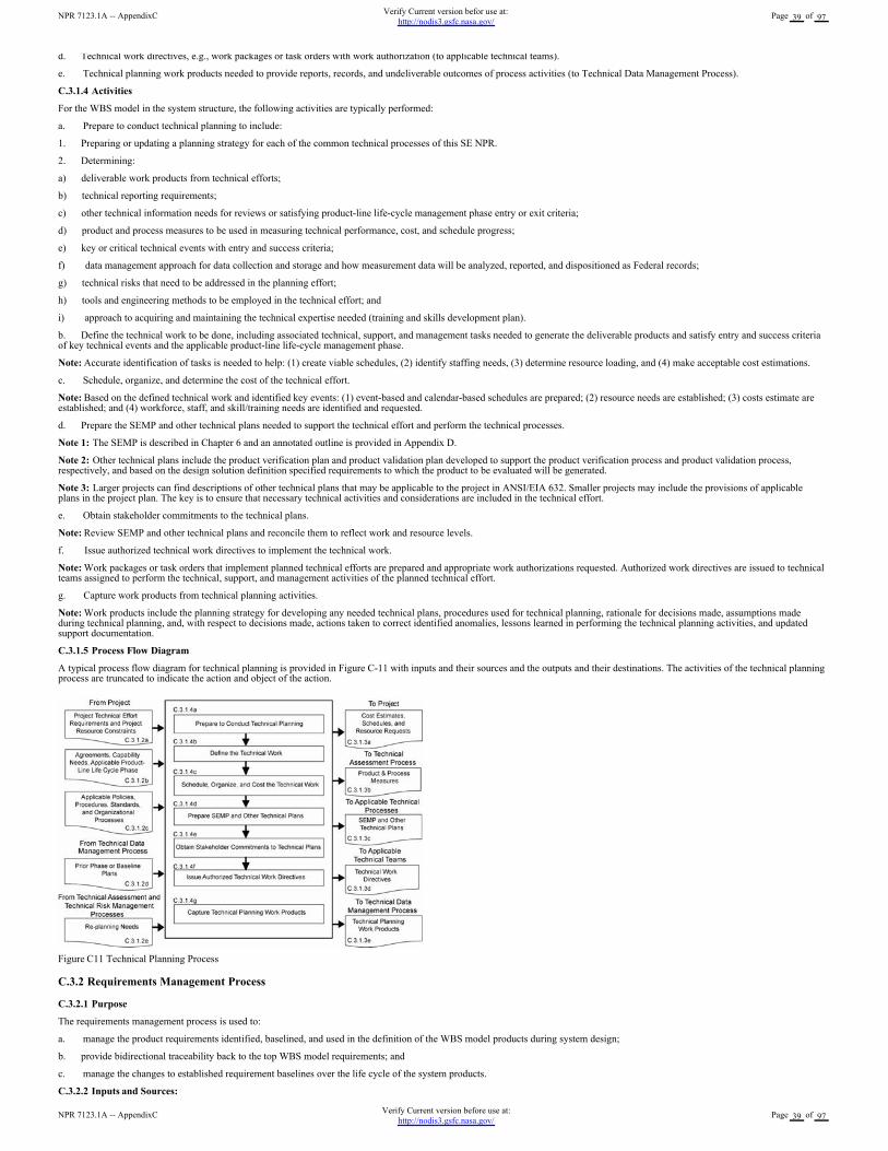
d. Technical work directives, e.g., work packages or task orders with work authorization (to applicable technical teams).
e. Technical planning work products needed to provide reports, records, and undeliverable outcomes of process activities (to Technical Data Management Process).
C.3.1.4 Activities
For the WBS model in the system structure, the following activities are typically performed:
a. Prepare to conduct technical planning to include:
1. Preparing or updating a planning strategy for each of the common technical processes of this SE NPR.
2. Determining:
a) deliverable work products from technical efforts;
b) technical reporting requirements;
c) other technical information needs for reviews or satisfying product-line life-cycle management phase entry or exit criteria;
d) product and process measures to be used in measuring technical performance, cost, and schedule progress;
e) key or critical technical events with entry and success criteria;
f) data management approach for data collection and storage and how measurement data will be analyzed, reported, and dispositioned as Federal records;
g) technical risks that need to be addressed in the planning effort;
h) tools and engineering methods to be employed in the technical effort; and
i) approach to acquiring and maintaining the technical expertise needed (training and skills development plan).
b. Define the technical work to be done, including associated technical, support, and management tasks needed to generate the deliverable products and satisfy entry and success criteriaof key technical events and the applicable product-line life-cycle management phase.
Note: Accurate identification of tasks is needed to help: (1) create viable schedules, (2) identify staffing needs, (3) determine resource loading, and (4) make acceptable cost estimations.
c. Schedule, organize, and determine the cost of the technical effort.
Note: Based on the defined technical work and identified key events: (1) event-based and calendar-based schedules are prepared; (2) resource needs are established; (3) costs estimate areestablished; and (4) workforce, staff, and skill/training needs are identified and requested.
d. Prepare the SEMP and other technical plans needed to support the technical effort and perform the technical processes.
Note 1: The SEMP is described in Chapter 6 and an annotated outline is provided in Appendix D.
Note 2: Other technical plans include the product verification plan and product validation plan developed to support the product verification process and product validation process,respectively, and based on the design solution definition specified requirements to which the product to be evaluated will be generated.
Note 3: Larger projects can find descriptions of other technical plans that may be applicable to the project in ANSI/EIA 632. Smaller projects may include the provisions of applicableplans in the project plan. The key is to ensure that necessary technical activities and considerations are included in the technical effort.
e. Obtain stakeholder commitments to the technical plans.
Note: Review SEMP and other technical plans and reconcile them to reflect work and resource levels.
f. Issue authorized technical work directives to implement the technical work.
Note: Work packages or task orders that implement planned technical efforts are prepared and appropriate work authorizations requested. Authorized work directives are issued to technicalteams assigned to perform the technical, support, and management activities of the planned technical effort.
g. Capture work products from technical planning activities.
Note: Work products include the planning strategy for developing any needed technical plans, procedures used for technical planning, rationale for decisions made, assumptions madeduring technical planning, and, with respect to decisions made, actions taken to correct identified anomalies, lessons learned in performing the technical planning activities, and updatedsupport documentation.
C.3.1.5 Process Flow Diagram
A typical process flow diagram for technical planning is provided in Figure C-11 with inputs and their sources and the outputs and their destinations. The activities of the technical planningprocess are truncated to indicate the action and object of the action.
Figure C11 Technical Planning Process
C.3.2 Requirements Management Process
C.3.2.1 Purpose
The requirements management process is used to:
a. manage the product requirements identified, baselined, and used in the definition of the WBS model products during system design;
b. provide bidirectional traceability back to the top WBS model requirements; and
c. manage the changes to established requirement baselines over the life cycle of the system products.
C.3.2.2 Inputs and Sources:
NPR 7123.1A -- AppendixCVerify Current version before use at:
http://nodis3.gsfc.nasa.gov/Page 39 of 97
NPR 7123.1A -- AppendixCVerify Current version befor use at:
http://nodis3.gsfc.nasa.gov/Page 39 of 97
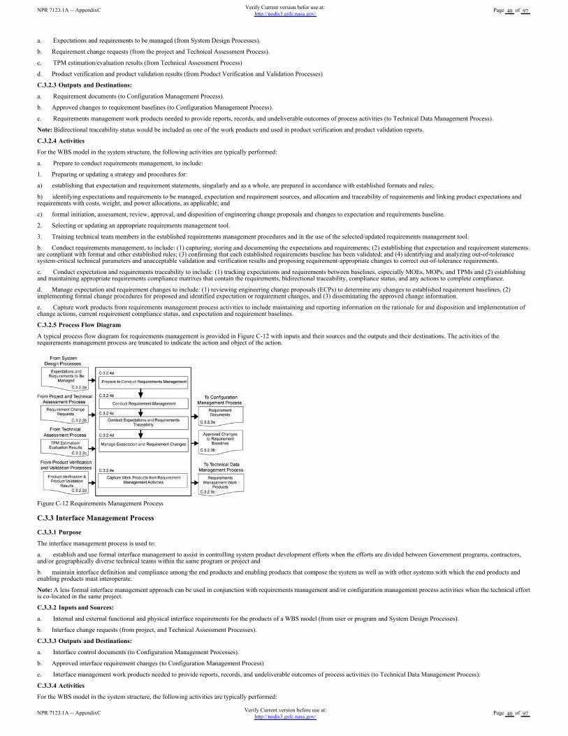
a. Expectations and requirements to be managed (from System Design Processes).
b. Requirement change requests (from the project and Technical Assessment Process).
c. TPM estimation/evaluation results (from Technical Assessment Process)
d. Product verification and product validation results (from Product Verification and Validation Processes)
C.3.2.3 Outputs and Destinations:
a. Requirement documents (to Configuration Management Process).
b. Approved changes to requirement baselines (to Configuration Management Process).
c. Requirements management work products needed to provide reports, records, and undeliverable outcomes of process activities (to Technical Data Management Process).
Note: Bidirectional traceability status would be included as one of the work products and used in product verification and product validation reports.
C.3.2.4 Activities
For the WBS model in the system structure, the following activities are typically performed:
a. Prepare to conduct requirements management, to include:
1. Preparing or updating a strategy and procedures for:
a) establishing that expectation and requirement statements, singularly and as a whole, are prepared in accordance with established formats and rules;
b) identifying expectations and requirements to be managed, expectation and requirement sources, and allocation and traceability of requirements and linking product expectations andrequirements with costs, weight, and power allocations, as applicable; and
c) formal initiation, assessment, review, approval, and disposition of engineering change proposals and changes to expectation and requirements baseline.
2. Selecting or updating an appropriate requirements management tool.
3. Training technical team members in the established requirements management procedures and in the use of the selected/updated requirements management tool.
b. Conduct requirements management, to include: (1) capturing, storing and documenting the expectations and requirements; (2) establishing that expectation and requirement statementsare compliant with format and other established rules; (3) confirming that each established requirements baseline has been validated; and (4) identifying and analyzing out-of-tolerancesystem-critical technical parameters and unacceptable validation and verification results and proposing requirement-appropriate changes to correct out-of-tolerance requirements.
c. Conduct expectation and requirements traceability to include: (1) tracking expectations and requirements between baselines, especially MOEs, MOPs, and TPMs and (2) establishingand maintaining appropriate requirements compliance matrixes that contain the requirements, bidirectional traceability, compliance status, and any actions to complete compliance.
d. Manage expectation and requirement changes to include: (1) reviewing engineering change proposals (ECPs) to determine any changes to established requirement baselines, (2)implementing formal change procedures for proposed and identified expectation or requirement changes, and (3) disseminating the approved change information.
e. Capture work products from requirements management process activities to include maintaining and reporting information on the rationale for and disposition and implementation ofchange actions, current requirement compliance status, and expectation and requirement baselines.
C.3.2.5 Process Flow Diagram
A typical process flow diagram for requirements management is provided in Figure C-12 with inputs and their sources and the outputs and their destinations. The activities of therequirements management process are truncated to indicate the action and object of the action.
Figure C-12 Requirements Management Process
C.3.3 Interface Management Process
C.3.3.1 Purpose
The interface management process is used to:
a. establish and use formal interface management to assist in controlling system product development efforts when the efforts are divided between Government programs, contractors,and/or geographically diverse technical teams within the same program or project and
b. maintain interface definition and compliance among the end products and enabling products that compose the system as well as with other systems with which the end products andenabling products must interoperate.
Note: A less formal interface management approach can be used in conjunction with requirements management and/or configuration management process activities when the technical effortis co-located in the same project.
C.3.3.2 Inputs and Sources:
a. Internal and external functional and physical interface requirements for the products of a WBS model (from user or program and System Design Processes).
b. Interface change requests (from project, and Technical Assessment Processes).
C.3.3.3 Outputs and Destinations:
a. Interface control documents (to Configuration Management Processes).
b. Approved interface requirement changes (to Configuration Management Process)
c. Interface management work products needed to provide reports, records, and undeliverable outcomes of process activities (to Technical Data Management Process).
C.3.3.4 Activities
For the WBS model in the system structure, the following activities are typically performed:
NPR 7123.1A -- AppendixCVerify Current version before use at:
http://nodis3.gsfc.nasa.gov/Page 40 of 97
NPR 7123.1A -- AppendixCVerify Current version befor use at:
http://nodis3.gsfc.nasa.gov/Page 40 of 97
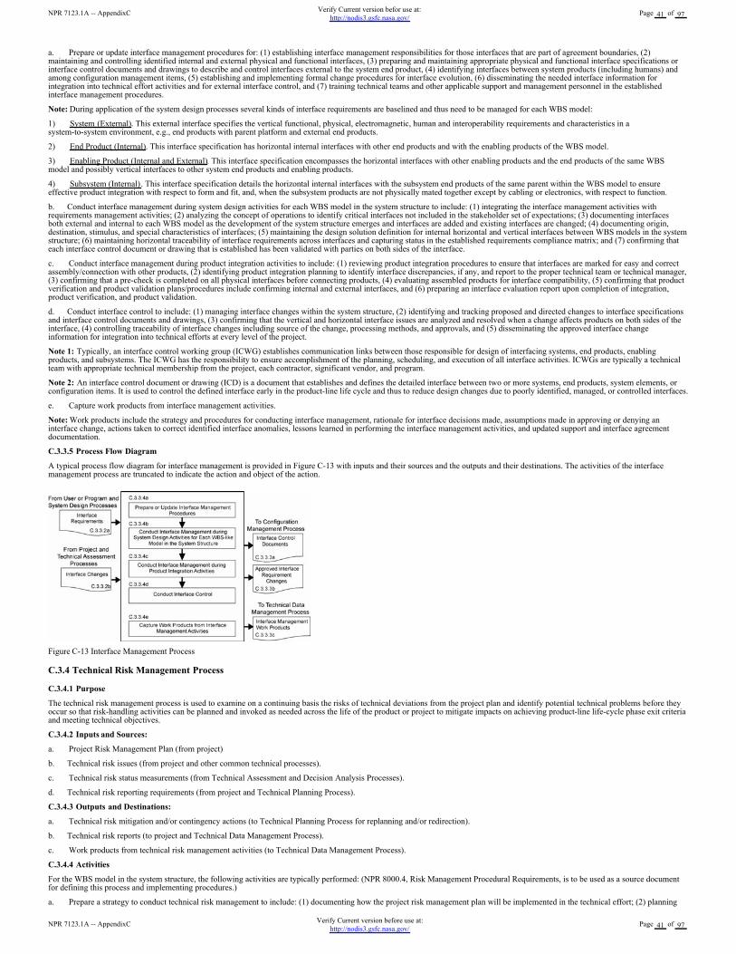
a. Prepare or update interface management procedures for: (1) establishing interface management responsibilities for those interfaces that are part of agreement boundaries, (2)maintaining and controlling identified internal and external physical and functional interfaces, (3) preparing and maintaining appropriate physical and functional interface specifications orinterface control documents and drawings to describe and control interfaces external to the system end product, (4) identifying interfaces between system products (including humans) andamong configuration management items, (5) establishing and implementing formal change procedures for interface evolution, (6) disseminating the needed interface information forintegration into technical effort activities and for external interface control, and (7) training technical teams and other applicable support and management personnel in the establishedinterface management procedures.
Note: During application of the system design processes several kinds of interface requirements are baselined and thus need to be managed for each WBS model:
1) System (External). This external interface specifies the vertical functional, physical, electromagnetic, human and interoperability requirements and characteristics in asystem-to-system environment, e.g., end products with parent platform and external end products.
2) End Product (Internal). This interface specification has horizontal internal interfaces with other end products and with the enabling products of the WBS model.
3) Enabling Product (Internal and External). This interface specification encompasses the horizontal interfaces with other enabling products and the end products of the same WBSmodel and possibly vertical interfaces to other system end products and enabling products.
4) Subsystem (Internal). This interface specification details the horizontal internal interfaces with the subsystem end products of the same parent within the WBS model to ensureeffective product integration with respect to form and fit, and, when the subsystem products are not physically mated together except by cabling or electronics, with respect to function.
b. Conduct interface management during system design activities for each WBS model in the system structure to include: (1) integrating the interface management activities withrequirements management activities; (2) analyzing the concept of operations to identify critical interfaces not included in the stakeholder set of expectations; (3) documenting interfacesboth external and internal to each WBS model as the development of the system structure emerges and interfaces are added and existing interfaces are changed; (4) documenting origin,destination, stimulus, and special characteristics of interfaces; (5) maintaining the design solution definition for internal horizontal and vertical interfaces between WBS models in the systemstructure; (6) maintaining horizontal traceability of interface requirements across interfaces and capturing status in the established requirements compliance matrix; and (7) confirming thateach interface control document or drawing that is established has been validated with parties on both sides of the interface.
c. Conduct interface management during product integration activities to include: (1) reviewing product integration procedures to ensure that interfaces are marked for easy and correctassembly/connection with other products, (2) identifying product integration planning to identify interface discrepancies, if any, and report to the proper technical team or technical manager,(3) confirming that a pre-check is completed on all physical interfaces before connecting products, (4) evaluating assembled products for interface compatibility, (5) confirming that productverification and product validation plans/procedures include confirming internal and external interfaces, and (6) preparing an interface evaluation report upon completion of integration,product verification, and product validation.
d. Conduct interface control to include: (1) managing interface changes within the system structure, (2) identifying and tracking proposed and directed changes to interface specificationsand interface control documents and drawings, (3) confirming that the vertical and horizontal interface issues are analyzed and resolved when a change affects products on both sides of theinterface, (4) controlling traceability of interface changes including source of the change, processing methods, and approvals, and (5) disseminating the approved interface changeinformation for integration into technical efforts at every level of the project.
Note 1: Typically, an interface control working group (ICWG) establishes communication links between those responsible for design of interfacing systems, end products, enablingproducts, and subsystems. The ICWG has the responsibility to ensure accomplishment of the planning, scheduling, and execution of all interface activities. ICWGs are typically a technicalteam with appropriate technical membership from the project, each contractor, significant vendor, and program.
Note 2: An interface control document or drawing (ICD) is a document that establishes and defines the detailed interface between two or more systems, end products, system elements, orconfiguration items. It is used to control the defined interface early in the product-line life cycle and thus to reduce design changes due to poorly identified, managed, or controlled interfaces.
e. Capture work products from interface management activities.
Note: Work products include the strategy and procedures for conducting interface management, rationale for interface decisions made, assumptions made in approving or denying aninterface change, actions taken to correct identified interface anomalies, lessons learned in performing the interface management activities, and updated support and interface agreementdocumentation.
C.3.3.5 Process Flow Diagram
A typical process flow diagram for interface management is provided in Figure C-13 with inputs and their sources and the outputs and their destinations. The activities of the interfacemanagement process are truncated to indicate the action and object of the action.
Figure C-13 Interface Management Process
C.3.4 Technical Risk Management Process
C.3.4.1 Purpose
The technical risk management process is used to examine on a continuing basis the risks of technical deviations from the project plan and identify potential technical problems before theyoccur so that risk-handling activities can be planned and invoked as needed across the life of the product or project to mitigate impacts on achieving product-line life-cycle phase exit criteriaand meeting technical objectives.
C.3.4.2 Inputs and Sources:
a. Project Risk Management Plan (from project)
b. Technical risk issues (from project and other common technical processes).
c. Technical risk status measurements (from Technical Assessment and Decision Analysis Processes).
d. Technical risk reporting requirements (from project and Technical Planning Process).
C.3.4.3 Outputs and Destinations:
a. Technical risk mitigation and/or contingency actions (to Technical Planning Process for replanning and/or redirection).
b. Technical risk reports (to project and Technical Data Management Process).
c. Work products from technical risk management activities (to Technical Data Management Process).
C.3.4.4 Activities
For the WBS model in the system structure, the following activities are typically performed: (NPR 8000.4, Risk Management Procedural Requirements, is to be used as a source documentfor defining this process and implementing procedures.)
a. Prepare a strategy to conduct technical risk management to include: (1) documenting how the project risk management plan will be implemented in the technical effort; (2) planning
NPR 7123.1A -- AppendixCVerify Current version before use at:
http://nodis3.gsfc.nasa.gov/Page 41 of 97
NPR 7123.1A -- AppendixCVerify Current version befor use at:
http://nodis3.gsfc.nasa.gov/Page 41 of 97
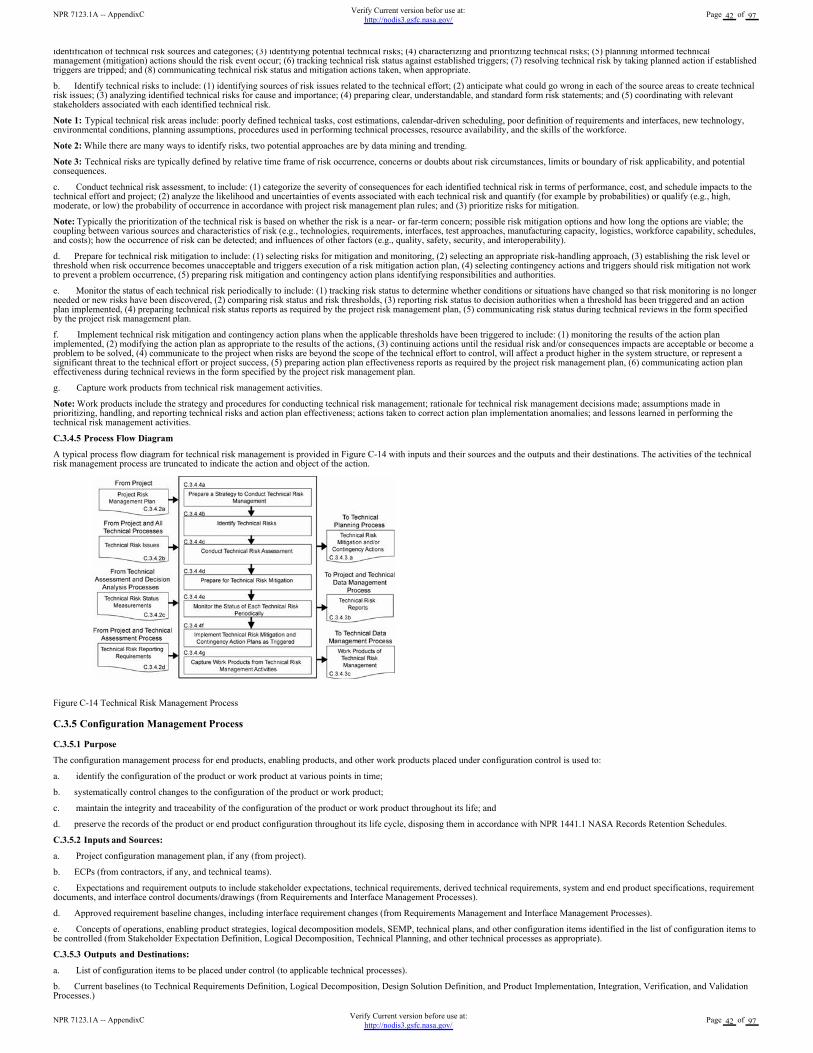
identification of technical risk sources and categories; (3) identifying potential technical risks; (4) characterizing and prioritizing technical risks; (5) planning informed technicalmanagement (mitigation) actions should the risk event occur; (6) tracking technical risk status against established triggers; (7) resolving technical risk by taking planned action if establishedtriggers are tripped; and (8) communicating technical risk status and mitigation actions taken, when appropriate.
b. Identify technical risks to include: (1) identifying sources of risk issues related to the technical effort; (2) anticipate what could go wrong in each of the source areas to create technicalrisk issues; (3) analyzing identified technical risks for cause and importance; (4) preparing clear, understandable, and standard form risk statements; and (5) coordinating with relevantstakeholders associated with each identified technical risk.
Note 1: Typical technical risk areas include: poorly defined technical tasks, cost estimations, calendar-driven scheduling, poor definition of requirements and interfaces, new technology,environmental conditions, planning assumptions, procedures used in performing technical processes, resource availability, and the skills of the workforce.
Note 2: While there are many ways to identify risks, two potential approaches are by data mining and trending.
Note 3: Technical risks are typically defined by relative time frame of risk occurrence, concerns or doubts about risk circumstances, limits or boundary of risk applicability, and potentialconsequences.
c. Conduct technical risk assessment, to include: (1) categorize the severity of consequences for each identified technical risk in terms of performance, cost, and schedule impacts to thetechnical effort and project; (2) analyze the likelihood and uncertainties of events associated with each technical risk and quantify (for example by probabilities) or qualify (e.g., high,moderate, or low) the probability of occurrence in accordance with project risk management plan rules; and (3) prioritize risks for mitigation.
Note: Typically the prioritization of the technical risk is based on whether the risk is a near- or far-term concern; possible risk mitigation options and how long the options are viable; thecoupling between various sources and characteristics of risk (e.g., technologies, requirements, interfaces, test approaches, manufacturing capacity, logistics, workforce capability, schedules,and costs); how the occurrence of risk can be detected; and influences of other factors (e.g., quality, safety, security, and interoperability).
d. Prepare for technical risk mitigation to include: (1) selecting risks for mitigation and monitoring, (2) selecting an appropriate risk-handling approach, (3) establishing the risk level orthreshold when risk occurrence becomes unacceptable and triggers execution of a risk mitigation action plan, (4) selecting contingency actions and triggers should risk mitigation not workto prevent a problem occurrence, (5) preparing risk mitigation and contingency action plans identifying responsibilities and authorities.
e. Monitor the status of each technical risk periodically to include: (1) tracking risk status to determine whether conditions or situations have changed so that risk monitoring is no longerneeded or new risks have been discovered, (2) comparing risk status and risk thresholds, (3) reporting risk status to decision authorities when a threshold has been triggered and an actionplan implemented, (4) preparing technical risk status reports as required by the project risk management plan, (5) communicating risk status during technical reviews in the form specifiedby the project risk management plan.
f. Implement technical risk mitigation and contingency action plans when the applicable thresholds have been triggered to include: (1) monitoring the results of the action planimplemented, (2) modifying the action plan as appropriate to the results of the actions, (3) continuing actions until the residual risk and/or consequences impacts are acceptable or become aproblem to be solved, (4) communicate to the project when risks are beyond the scope of the technical effort to control, will affect a product higher in the system structure, or represent asignificant threat to the technical effort or project success, (5) preparing action plan effectiveness reports as required by the project risk management plan, (6) communicating action planeffectiveness during technical reviews in the form specified by the project risk management plan.
g. Capture work products from technical risk management activities.
Note: Work products include the strategy and procedures for conducting technical risk management; rationale for technical risk management decisions made; assumptions made inprioritizing, handling, and reporting technical risks and action plan effectiveness; actions taken to correct action plan implementation anomalies; and lessons learned in performing thetechnical risk management activities.
C.3.4.5 Process Flow Diagram
A typical process flow diagram for technical risk management is provided in Figure C-14 with inputs and their sources and the outputs and their destinations. The activities of the technicalrisk management process are truncated to indicate the action and object of the action.
Figure C-14 Technical Risk Management Process
C.3.5 Configuration Management Process
C.3.5.1 Purpose
The configuration management process for end products, enabling products, and other work products placed under configuration control is used to:
a. identify the configuration of the product or work product at various points in time;
b. systematically control changes to the configuration of the product or work product;
c. maintain the integrity and traceability of the configuration of the product or work product throughout its life; and
d. preserve the records of the product or end product configuration throughout its life cycle, disposing them in accordance with NPR 1441.1 NASA Records Retention Schedules.
C.3.5.2 Inputs and Sources:
a. Project configuration management plan, if any (from project).
b. ECPs (from contractors, if any, and technical teams).
c. Expectations and requirement outputs to include stakeholder expectations, technical requirements, derived technical requirements, system and end product specifications, requirementdocuments, and interface control documents/drawings (from Requirements and Interface Management Processes).
d. Approved requirement baseline changes, including interface requirement changes (from Requirements Management and Interface Management Processes).
e. Concepts of operations, enabling product strategies, logical decomposition models, SEMP, technical plans, and other configuration items identified in the list of configuration items tobe controlled (from Stakeholder Expectation Definition, Logical Decomposition, Technical Planning, and other technical processes as appropriate).
C.3.5.3 Outputs and Destinations:
a. List of configuration items to be placed under control (to applicable technical processes).
b. Current baselines (to Technical Requirements Definition, Logical Decomposition, Design Solution Definition, and Product Implementation, Integration, Verification, and ValidationProcesses.)
NPR 7123.1A -- AppendixCVerify Current version before use at:
http://nodis3.gsfc.nasa.gov/Page 42 of 97
NPR 7123.1A -- AppendixCVerify Current version befor use at:
http://nodis3.gsfc.nasa.gov/Page 42 of 97
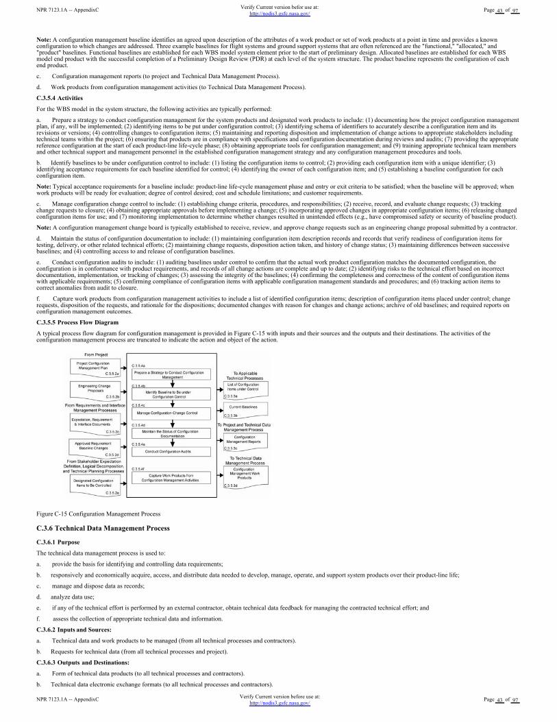
Note: A configuration management baseline identifies an agreed upon description of the attributes of a work product or set of work products at a point in time and provides a knownconfiguration to which changes are addressed. Three example baselines for flight systems and ground support systems that are often referenced are the "functional," "allocated," and"product" baselines. Functional baselines are established for each WBS model system element prior to the start of preliminary design. Allocated baselines are established for each WBSmodel end product with the successful completion of a Preliminary Design Review (PDR) at each level of the system structure. The product baseline represents the configuration of eachend product.
c. Configuration management reports (to project and Technical Data Management Process).
d. Work products from configuration management activities (to Technical Data Management Process).
C.3.5.4 Activities
For the WBS model in the system structure, the following activities are typically performed:
a. Prepare a strategy to conduct configuration management for the system products and designated work products to include: (1) documenting how the project configuration managementplan, if any, will be implemented; (2) identifying items to be put under configuration control; (3) identifying schema of identifiers to accurately describe a configuration item and itsrevisions or versions; (4) controlling changes to configuration items; (5) maintaining and reporting disposition and implementation of change actions to appropriate stakeholders includingtechnical teams within the project; (6) ensuring that products are in compliance with specifications and configuration documentation during reviews and audits; (7) providing the appropriatereference configuration at the start of each product-line life-cycle phase; (8) obtaining appropriate tools for configuration management; and (9) training appropriate technical team membersand other technical support and management personnel in the established configuration management strategy and any configuration management procedures and tools.
b. Identify baselines to be under configuration control to include: (1) listing the configuration items to control; (2) providing each configuration item with a unique identifier; (3)identifying acceptance requirements for each baseline identified for control; (4) identifying the owner of each configuration item; and (5) establishing a baseline configuration for eachconfiguration item.
Note: Typical acceptance requirements for a baseline include: product-line life-cycle management phase and entry or exit criteria to be satisfied; when the baseline will be approved; whenwork products will be ready for evaluation; degree of control desired; cost and schedule limitations; and customer requirements.
c. Manage configuration change control to include: (1) establishing change criteria, procedures, and responsibilities; (2) receive, record, and evaluate change requests; (3) trackingchange requests to closure; (4) obtaining appropriate approvals before implementing a change; (5) incorporating approved changes in appropriate configuration items; (6) releasing changedconfiguration items for use; and (7) monitoring implementation to determine whether changes resulted in unintended effects (e.g., have compromised safety or security of baseline product).
Note: A configuration management change board is typically established to receive, review, and approve change requests such as an engineering change proposal submitted by a contractor.
d. Maintain the status of configuration documentation to include: (1) maintaining configuration item description records and records that verify readiness of configuration items fortesting, delivery, or other related technical efforts; (2) maintaining change requests, disposition action taken, and history of change status; (3) maintaining differences between successivebaselines; and (4) controlling access to and release of configuration baselines.
e. Conduct configuration audits to include: (1) auditing baselines under control to confirm that the actual work product configuration matches the documented configuration, theconfiguration is in conformance with product requirements, and records of all change actions are complete and up to date; (2) identifying risks to the technical effort based on incorrectdocumentation, implementation, or tracking of changes; (3) assessing the integrity of the baselines; (4) confirming the completeness and correctness of the content of configuration itemswith applicable requirements; (5) confirming compliance of configuration items with applicable configuration management standards and procedures; and (6) tracking action items tocorrect anomalies from audit to closure.
f. Capture work products from configuration management activities to include a list of identified configuration items; description of configuration items placed under control; changerequests, disposition of the requests, and rationale for the dispositions; documented changes with reason for changes and change actions; archive of old baselines; and required reports onconfiguration management outcomes.
C.3.5.5 Process Flow Diagram
A typical process flow diagram for configuration management is provided in Figure C-15 with inputs and their sources and the outputs and their destinations. The activities of theconfiguration management process are truncated to indicate the action and object of the action.
Figure C-15 Configuration Management Process
C.3.6 Technical Data Management Process
C.3.6.1 Purpose
The technical data management process is used to:
a. provide the basis for identifying and controlling data requirements;
b. responsively and economically acquire, access, and distribute data needed to develop, manage, operate, and support system products over their product-line life;
c. manage and dispose data as records;
d. analyze data use;
e. if any of the technical effort is performed by an external contractor, obtain technical data feedback for managing the contracted technical effort; and
f. assess the collection of appropriate technical data and information.
C.3.6.2 Inputs and Sources:
a. Technical data and work products to be managed (from all technical processes and contractors).
b. Requests for technical data (from all technical processes and project).
C.3.6.3 Outputs and Destinations:
a. Form of technical data products (to all technical processes and contractors).
b. Technical data electronic exchange formats (to all technical processes and contractors).
NPR 7123.1A -- AppendixCVerify Current version before use at:
http://nodis3.gsfc.nasa.gov/Page 43 of 97
NPR 7123.1A -- AppendixCVerify Current version befor use at:
http://nodis3.gsfc.nasa.gov/Page 43 of 97
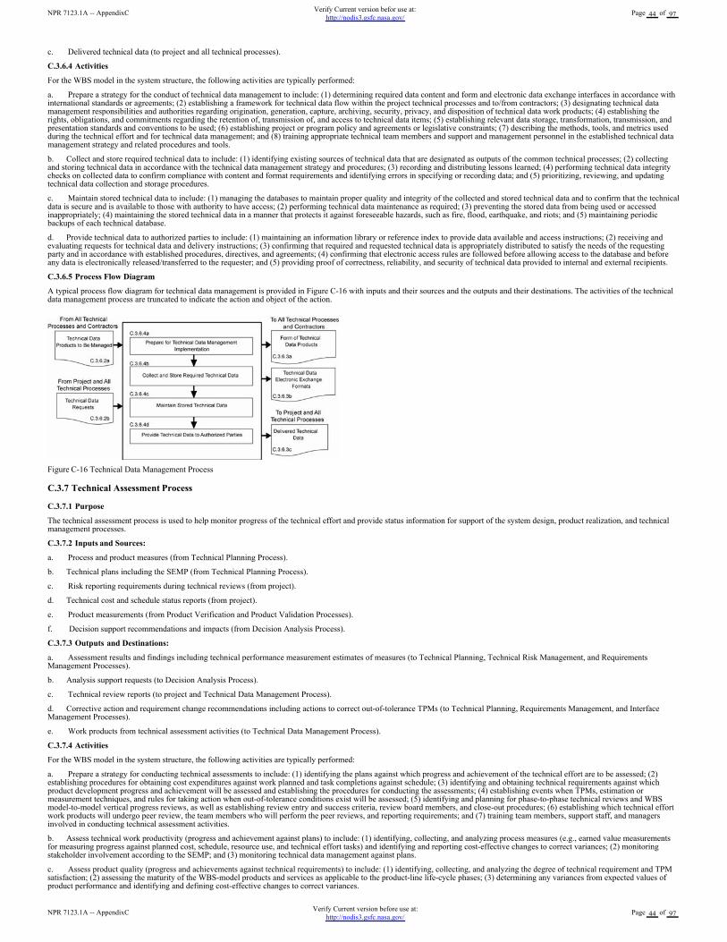
c. Delivered technical data (to project and all technical processes).
C.3.6.4 Activities
For the WBS model in the system structure, the following activities are typically performed:
a. Prepare a strategy for the conduct of technical data management to include: (1) determining required data content and form and electronic data exchange interfaces in accordance withinternational standards or agreements; (2) establishing a framework for technical data flow within the project technical processes and to/from contractors; (3) designating technical datamanagement responsibilities and authorities regarding origination, generation, capture, archiving, security, privacy, and disposition of technical data work products; (4) establishing therights, obligations, and commitments regarding the retention of, transmission of, and access to technical data items; (5) establishing relevant data storage, transformation, transmission, andpresentation standards and conventions to be used; (6) establishing project or program policy and agreements or legislative constraints; (7) describing the methods, tools, and metrics usedduring the technical effort and for technical data management; and (8) training appropriate technical team members and support and management personnel in the established technical datamanagement strategy and related procedures and tools.
b. Collect and store required technical data to include: (1) identifying existing sources of technical data that are designated as outputs of the common technical processes; (2) collectingand storing technical data in accordance with the technical data management strategy and procedures; (3) recording and distributing lessons learned; (4) performing technical data integritychecks on collected data to confirm compliance with content and format requirements and identifying errors in specifying or recording data; and (5) prioritizing, reviewing, and updatingtechnical data collection and storage procedures.
c. Maintain stored technical data to include: (1) managing the databases to maintain proper quality and integrity of the collected and stored technical data and to confirm that the technicaldata is secure and is available to those with authority to have access; (2) performing technical data maintenance as required; (3) preventing the stored data from being used or accessedinappropriately; (4) maintaining the stored technical data in a manner that protects it against foreseeable hazards, such as fire, flood, earthquake, and riots; and (5) maintaining periodicbackups of each technical database.
d. Provide technical data to authorized parties to include: (1) maintaining an information library or reference index to provide data available and access instructions; (2) receiving andevaluating requests for technical data and delivery instructions; (3) confirming that required and requested technical data is appropriately distributed to satisfy the needs of the requestingparty and in accordance with established procedures, directives, and agreements; (4) confirming that electronic access rules are followed before allowing access to the database and beforeany data is electronically released/transferred to the requester; and (5) providing proof of correctness, reliability, and security of technical data provided to internal and external recipients.
C.3.6.5 Process Flow Diagram
A typical process flow diagram for technical data management is provided in Figure C-16 with inputs and their sources and the outputs and their destinations. The activities of the technicaldata management process are truncated to indicate the action and object of the action.
Figure C-16 Technical Data Management Process
C.3.7 Technical Assessment Process
C.3.7.1 Purpose
The technical assessment process is used to help monitor progress of the technical effort and provide status information for support of the system design, product realization, and technicalmanagement processes.
C.3.7.2 Inputs and Sources:
a. Process and product measures (from Technical Planning Process).
b. Technical plans including the SEMP (from Technical Planning Process).
c. Risk reporting requirements during technical reviews (from project).
d. Technical cost and schedule status reports (from project).
e. Product measurements (from Product Verification and Product Validation Processes).
f. Decision support recommendations and impacts (from Decision Analysis Process).
C.3.7.3 Outputs and Destinations:
a. Assessment results and findings including technical performance measurement estimates of measures (to Technical Planning, Technical Risk Management, and RequirementsManagement Processes).
b. Analysis support requests (to Decision Analysis Process).
c. Technical review reports (to project and Technical Data Management Process).
d. Corrective action and requirement change recommendations including actions to correct out-of-tolerance TPMs (to Technical Planning, Requirements Management, and InterfaceManagement Processes).
e. Work products from technical assessment activities (to Technical Data Management Process).
C.3.7.4 Activities
For the WBS model in the system structure, the following activities are typically performed:
a. Prepare a strategy for conducting technical assessments to include: (1) identifying the plans against which progress and achievement of the technical effort are to be assessed; (2)establishing procedures for obtaining cost expenditures against work planned and task completions against schedule; (3) identifying and obtaining technical requirements against whichproduct development progress and achievement will be assessed and establishing the procedures for conducting the assessments; (4) establishing events when TPMs, estimation ormeasurement techniques, and rules for taking action when out-of-tolerance conditions exist will be assessed; (5) identifying and planning for phase-to-phase technical reviews and WBSmodel-to-model vertical progress reviews, as well as establishing review entry and success criteria, review board members, and close-out procedures; (6) establishing which technical effortwork products will undergo peer review, the team members who will perform the peer reviews, and reporting requirements; and (7) training team members, support staff, and managersinvolved in conducting technical assessment activities.
b. Assess technical work productivity (progress and achievement against plans) to include: (1) identifying, collecting, and analyzing process measures (e.g., earned value measurementsfor measuring progress against planned cost, schedule, resource use, and technical effort tasks) and identifying and reporting cost-effective changes to correct variances; (2) monitoringstakeholder involvement according to the SEMP; and (3) monitoring technical data management against plans.
c. Assess product quality (progress and achievements against technical requirements) to include: (1) identifying, collecting, and analyzing the degree of technical requirement and TPMsatisfaction; (2) assessing the maturity of the WBS-model products and services as applicable to the product-line life-cycle phases; (3) determining any variances from expected values ofproduct performance and identifying and defining cost-effective changes to correct variances.
NPR 7123.1A -- AppendixCVerify Current version before use at:
http://nodis3.gsfc.nasa.gov/Page 44 of 97
NPR 7123.1A -- AppendixCVerify Current version befor use at:
http://nodis3.gsfc.nasa.gov/Page 44 of 97
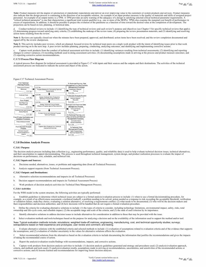
Note: Product measures tell the degree of satisfaction of stakeholder expectations and deliver an ever improving value to the customers of system products and services. Product measuresalso indicate that the design process is continuing in the direction of an acceptable solution. An example of an input product measure is the quality of materials and skills of assigned projectpersonnel. An example of an output metric is a TPM. A TPM provides an early warning of the adequacy of a design in satisfying selected critical technical parameter requirements. A"critical technical parameter" is one that characterizes a significant total system qualifier (e.g., one or more of the MOPs). TPMs also examine the marginal cost benefit of performance inexcess of requirements. In addition, it should be possible to project the evolution of the parameter as a function of time toward the desired value at the completion of development. Theprojection can be based on test, planning, or historical data.
d. Conduct technical reviews to include: (1) identifying the type of technical reviews and each review?s purpose and objectives (see Chapter 5 for specific technical reviews that apply);(2) determining progress toward satisfying entry criteria; (3) establishing the makeup of the review team; (4) preparing the review presentation materials; and (5) identifying and resolvingaction items resulting from the review.
Note 1: Reviews are typically closed out when the minutes have been prepared, approved, and distributed; action items have been resolved; and the review completion documented andsigned off by the review chairperson.
Note 2: This activity includes peer reviews, which are planned, focused reviews by technical team peers on a single work product with the intent of identifying issues prior to that workproduct moving on to the next step. A peer review includes planning, preparing, conducting, analyzing outcomes, and identifying and implementing corrective actions.
e. Capture work products from the conduct of technical assessment activities to include: (1) identifying variances resulting from technical assessments; (2) identifying and reportingchanges to correct variances; (3) recording methods used in doing assessment activities; (4) documenting assumptions made in arriving at the process and product measure outcomes; and(5) reporting corrective action recommendations.
C.3.7.5 Process Flow Diagram
A typical process flow diagram for technical assessment is provided in Figure C-17 with inputs and their sources and the outputs and their destinations. The activities of the technicalassessment process are truncated to indicate the action and object of the action.
Figure C17 Technical Assessment Process
C.3.8 Decision Analysis Process
C.3.8.1 Purpose
The decision analysis process including data collection (e.g., engineering performance, quality, and reliability data) is used to help evaluate technical decision issues, technical alternatives,and their uncertainties to support decisionmaking. This process is used throughout technical management, system design, and product realization processes to evaluate the impact ofdecisions on performance, cost, schedule, and technical risk.
C.3.8.2 Inputs and Sources:
a. Decisions needed, alternatives, issues, or problems and supporting data (from all Technical Processes).
b. Analysis support requests (from Technical Assessment Process).
C.3.8.3 Outputs and Destinations:
a. Alternative selection recommendations and impacts (to all Technical Processes)
b. Decision support recommendations and impacts (to Technical Assessment Process)
c. Work products of decision analysis activities (to Technical Data Management Process).
C.3.8.4 Activities
For the WBS model in the system structure, the following activities are typically performed:
a. Establish guidelines to determine which technical issues are subject to a formal analysis/evaluation process to include: (1) when to use a formal decisionmaking procedure, forexample, as a result of an effectiveness assessment, a technical tradeoff, a problem needing to be solved, action needed as a response to risk exceeding the acceptable threshold, verificationor validation failure, make/buy choice, evaluating a solution alternative, or resolving a requirements conflict; (2) what needs to be documented; (3) who will be the decision makers andtheir responsibilities and decision authorities; and (4) how decisions will be handled that do not require a formal evaluation procedure.
b. Define the criteria for evaluating alternative solutions to include: (1) the types of criteria to consider, including technology limitations, environmental impact, safety, risks, totalownership and life-cycle costs, and schedule impact; (2) the acceptable range and scale of the criteria; and (3) the rank of each criterion by its importance.
c. Identify alternative solutions to address decision issues to include alternatives for consideration in addition to those that may be provided with the issue.
d. Select evaluation methods and tools/techniques based on the purpose for analyzing a decision and on the availability of the information used to support the method and/or tool.
Note: Typical evaluation methods include: simulations; weighted trade-off matrices; engineering, manufacturing, cost, and technical opportunity studies; surveys;extrapolations based on field experience and prototypes; user review and comment; and testing.
e. Evaluate alternative solutions with the established criteria and selected methods to include: (1) evaluation of assumptions related to evaluation criteria and of the evidence that supportsthe assumptions; and (2) evaluation of whether uncertainty in the values for alternative solutions affects the evaluation.
f. Select recommended solutions from the alternatives based on the evaluation criteria to include documenting the information that justifies the recommendations and gives the impactsof taking the recommended course of action.
g. Report the analysis/evaluation results/findings with recommendations, impacts, and corrective actions.
h. Capture work products from decision analysis activities to include: (1) decision analysis guidelines generated and strategy and procedures used; (2) analysis/evaluation approach,criteria, and methods and tools used; (3) analysis/evaluation results, assumptions made in arriving at recommendations, uncertainties, and sensitivities of the recommended actions orcorrective actions; and (4) lessons learned and recommendations for improving future decision analyses.
NPR 7123.1A -- AppendixCVerify Current version before use at:
http://nodis3.gsfc.nasa.gov/Page 45 of 97
NPR 7123.1A -- AppendixCVerify Current version befor use at:
http://nodis3.gsfc.nasa.gov/Page 45 of 97
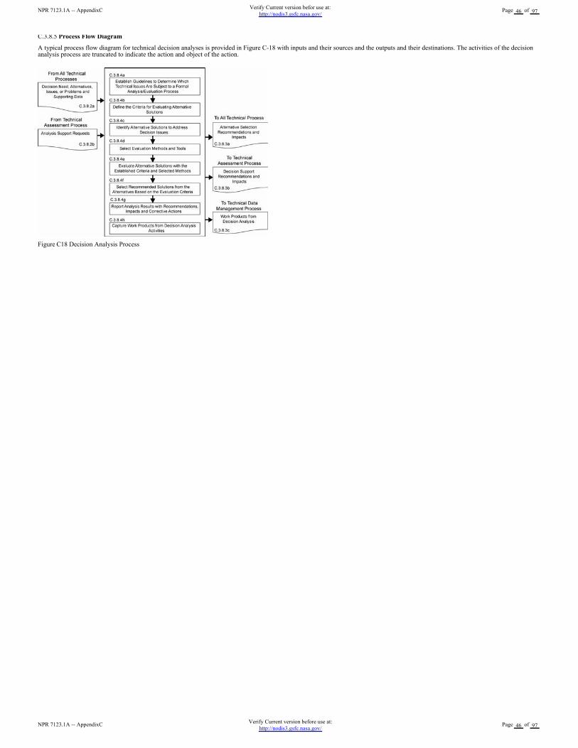
C.3.8.5 Process Flow Diagram
A typical process flow diagram for technical decision analyses is provided in Figure C-18 with inputs and their sources and the outputs and their destinations. The activities of the decisionanalysis process are truncated to indicate the action and object of the action.
Figure C18 Decision Analysis Process
NPR 7123.1A -- AppendixCVerify Current version before use at:
http://nodis3.gsfc.nasa.gov/Page 46 of 97
NPR 7123.1A -- AppendixCVerify Current version befor use at:
http://nodis3.gsfc.nasa.gov/Page 46 of 97

Appendix D. Systems Engineering Management Plan
D.1 Purpose and Use
The purpose of this appendix is to provide an annotated outline for a SEMP for use by NASA in planning the technical effort required for in-house and contracted projects. The SEMP is thetechnical planning document for systems engineering. The SEMP is designed to be a single, integrated technical planning document for the conduct and management of the requiredtechnical effort that is the responsibility of an in-house NASA project. The resulting technical plan is to represent the agreed-to and approved tailoring of the requirements of the SE NPR tosatisfy project technical requirements. The plan is to be used by the technical team responsible for generating technical work products to integrate and manage the full spectrum of technicalactivities required to engineer the system covered by the SEMP. The SEMP should be coordinated with the project plan for integration of the technical planning and modifications related tothe allocated resources, including cost, schedule, personnel, facilities, and deliverables required. The plan will also be used to evaluate the team?s technical approach, to make technical riskassessments, and to measure progress.
D.2 Terms Used
Terminology is a key factor in ensuring a common understanding of the technical effort to be accomplished. Terms used in the SEMP must have the same meaning as the terms used in theSE NPR.
D.3 SEMP Preparation
D.3.1 Outline Use
The SEMP outline in this appendix is to be used in preparing a project SEMP. For a small project the material in the SEMP can be placed in the project plan?s technical summary and thisannotated outline used as a topic guide.
D.3.2 Tailoring and Waivers
D.3.2.1
SEMP tailoring is to be consistent with the SE NPR tailoring requirements and guidelines. (See Appendix F.) The SEMP is to include documentation of any tailoring to the SE NPRrequirements and SEMP sections or subsections. Tailoring is an adaptation of a process or approach to meet a requirement, whereas a waiver is a documented agreement intentionallyreleasing a program or project from meeting a requirement. Tailored requirements will be documented directly following the heading of each affected SEMP section or subsection. TailoredSE NPR requirements that are not directly related to a SEMP section or subsection will be documented in the waiver section.
D.3.2.2
Approved waivers will be documented and incorporated into the waiver section of the SEMP.
D.3.3 Surveillance-Type Projects
For projects with significant portions of the engineering work contracted out, the SEMP should scope and plan the NASA project?s implementation of the common technical processesbefore, during, and at the completion of the contracted effort. This should include planning the technical team?s involvement in RFP preparation, in source selection activities, and inacceptance of deliverables. The interface activities with the contractor, including NASA technical team involvement with and monitoring of contracted work, should be a focus of theSEMP.
D.4 SEMP Annotated Outline
D.4.1 General Structure
The SEMP contains the following sections, unless they have been tailored out. Cross references to detailed information in related technical plans are included in each pertinent SEMPsection.
a. Purpose and Scope.
b. Applicable Documents and Designated Governing Authority.
c. Technical Summary.
d. Technical Effort Integration.
e. Common Technical Processes Implementation.
f. Technology Insertion.
g. Additional SE Functions and Activities.
h. Integration with the Project Plan Resource Allocation.
i. Waivers.
j. Appendices.
D.4.2 Purpose and Scope
This section provides a brief description of the purpose, scope, and content of the SEMP. The scope encompasses the SE technical effort required to generate the work products necessary tomeet the exit criteria for the product-line life-cycle phases.
D.4.3 Applicable Documents
This section lists the documents applicable to SEMP implementation and describes major standards and procedures that the technical effort needs to follow. Specific implementation of
NPR 7123.1A -- AppendixDVerify Current version before use at:
http://nodis3.gsfc.nasa.gov/Page 47 of 97
NPR 7123.1A -- AppendixDVerify Current version befor use at:
http://nodis3.gsfc.nasa.gov/Page 47 of 97
standardization tasking is incorporated into pertinent sections of the SEMP.
D.4.4 Technical Summary
This section contains an executive summary describing the problem to be solved by this technical effort.
D.4.4.1 System Description
This subsection contains a definition of the purpose of the system being developed and a brief description of the purpose of the products of the WBS models of the system structure forwhich this SEMP applies. Each WBS model includes the system end products and their subsystems and the supporting or enabling products and any other work products (plans, baselines)required for the development of the system. The description should include any interfacing systems and system products, including humans, with which the WBS model system productswill interact physically, functionally, or electronically.
D.4.4.2 System Structure
This subsection contains an explanation of how the WBS models will be developed, how the resulting WBS model will be integrated into the project WBS, and how the overall systemstructure will be developed. This subsection contains a description of the relationship of the specification tree and the drawing tree with the products of the system structure and how therelationship and interfaces of the system end products and their life-cycle-enabling products will be managed throughout the planned technical effort.
D.4.4.3 Product Integration
This subsection contains an explanation of how the product will be integrated and will describe clear organizational responsibilities and interdependencies whether the organizations aregeographically dispersed or managed across Centers.
D.4.4.4 Planning Context
This subsection contains the product-line life-cycle model constraints (e.g., NPR 7120.5) that affect the planning and implementation of the common technical processes to be applied inperforming the technical effort. The constraints provide a linkage of the technical effort with the applicable product-line life-cycle phases covered by the SEMP including, as applicable,milestone decision gates, major technical reviews, key intermediate events leading to project completion, life-cycle phase, event entry and exit criteria, and major baseline and other workproducts to be delivered to the sponsor or customer of the technical effort.
D.4.4.5 Boundary of Technical Effort
This subsection contains a description of the boundary of the general problem to be solved by the technical effort. Specifically, it identifies what can be controlled by the technical team(inside the boundary) and what influences the technical effort and is influenced by the technical effort but not controlled by the technical team (outside the boundary). Specific attentionshould be given to physical, functional, and electronic interfaces across the boundary.
D.4.4.6 Cross-References
This subsection contains cross-references to appropriate nontechnical plans that interface with the technical effort and contains a summary description of how the technical activities coveredin other plans are accomplished as fully integrated parts of the technical effort.
D.4.5 Technical Effort Integration
This section contains a description of how the various inputs to the technical effort will be integrated into a coordinated effort that meets cost, schedule, and performance objectives.
D.4.5.1 Responsibility and Authority
This subsection contains a description of the organizing structure for the technical teams assigned to this technical effort and includes how the teams will be staffed and managed, including:(a) what organization/panel will serve as the DGA for this project and, therefore, will have final signature authority for this SEMP; (b) how multidisciplinary teamwork will be achieved;(c) identification and definition of roles, responsibilities, and authorities required to perform the activities of each planned common technical process; (d) planned technical staffing bydiscipline and expertise level, with human resource loading; (e) required technical staff training; and (f) assignment of roles, responsibilities, and authorities to appropriate projectstakeholders or technical teams to assure planned activities are accomplished.
D.4.5.2 Contractor Integration
This subsection contains a description of how the technical effort of in-house and external contractors is to be integrated with the NASA technical team efforts. This includes establishingtechnical agreements, monitoring contractor progress against the agreement, handling technical work or product requirements change requests, and acceptance of deliverables. The sectionwill specifically address how interfaces between the NASA technical team and the contractor will be implemented for each of the 17 common technical processes. For example, it addresseshow the NASA technical team will be involved with reviewing or controlling contractor-generated design solution definition documentation or how the technical team will be involved withproduct verification and product validation activities.
D.4.5.3 Support Integration
This subsection contains a description of the methods (such as integrated computer-aided tool sets, integrated work product databases, and technical management information systems) thatwill be used to support technical effort integration.
D.4.6 Common Technical Processes Implementation
Each of the 17 common technical processes will have a separate subsection that contains the plan for performing the required process activities as appropriately tailored. (See Chapter 3 forthe process activities required and Appendix F for tailoring.) Implementation of the 17 common technical processes includes: (1) generating outcomes needed to satisfy the entry and exitcriteria of the applicable product-line life-cycle phase or phases identified in D.4.4.4 and (2) producing the necessary inputs for other technical processes. These sections contain adescription of the approach, methods, and tools for:
a. Identifying and obtaining adequate human and nonhuman resources for performing the planned process, developing the work products, and providing the services of the process.
b. Assigning responsibility and authority for performing the planned process, developing the work products, and providing the services of the process.
c. Training the technical staff performing or supporting the process, where training is identified as needed.
d. Designating and placing designated work products of the process under appropriate levels of configuration management.
e. Identifying and involving stakeholders of the process.
f. Monitoring and controlling the process.
g. Objectively evaluating adherence of the process and the work products and services of the process to the applicable requirements, objectives, and standards and addressing noncompliance.
h. Reviewing activities, status, and results of the process with appropriate levels of management and resolving issues.
D.4.7 Technology Insertion
This section contains a description of the approach and methods for identifying key technologies and their associated risks and criteria for assessing and inserting technologies, includingthose for inserting critical technologies from technology development projects.
D.4.8 Additional SE Functions and Activities
This section contains a description of other areas not specifically included in previous sections but that are essential for proper planning and conduct of the overall technical effort.
NPR 7123.1A -- AppendixDVerify Current version before use at:
http://nodis3.gsfc.nasa.gov/Page 48 of 97
NPR 7123.1A -- AppendixDVerify Current version befor use at:
http://nodis3.gsfc.nasa.gov/Page 48 of 97
D.4.8.1 System Safety
This subsection contains a description of the approach and methods for conducting safety analysis and assessing the risk to operators, the system, the environment, or the public.
D.4.8.2 Engineering Methods and Tools
This subsection contains a description of the methods and tools not included in D.4.7 that are needed to support the overall technical effort and identifies those tools to be acquired and tooltraining requirements.
D.4.8.3 Specialty Engineering
This subsection contains a description of engineering discipline and specialty requirements that apply across projects and the WBS models of the system structure. Examples of theserequirement areas include planning for safety, reliability, human factors, logistics, maintainability, quality, operability, and supportability.
D.4.9 Integration with the Project Plan and Technical Resource Allocation
This section contains how the technical effort will integrate with project management and defines roles and responsibilities. This section addresses how technical requirements will beintegrated with the project plan to determinate the allocation of resources, including cost, schedule, and personnel, and how changes to the allocations will be coordinated.
D.4.10 Waivers
This section contains all approved waivers to the Center Director?s SE NPR Implementation Plan requirement for the SEMP. This section also contains a separate subsection that includesany tailored SE NPR requirements that are not related and able to be documented in a specific SEMP section or subsection.
D.4.11 Appendices
Appendices are included, as necessary, to provide a glossary, acronyms and abbreviations, and information published separately for convenience in document maintenance. Included wouldbe: (a) information that may be pertinent to multiple topic areas (e.g., description of methods or procedures); (b) charts and proprietary data applicable to the technical efforts required in theSEMP; and (c) a summary of technical plans associated with the project. Each appendix should be referenced in one of the sections of the engineering plan where data would normally havebeen provided.
NPR 7123.1A -- AppendixDVerify Current version before use at:
http://nodis3.gsfc.nasa.gov/Page 49 of 97
NPR 7123.1A -- AppendixDVerify Current version befor use at:
http://nodis3.gsfc.nasa.gov/Page 49 of 97
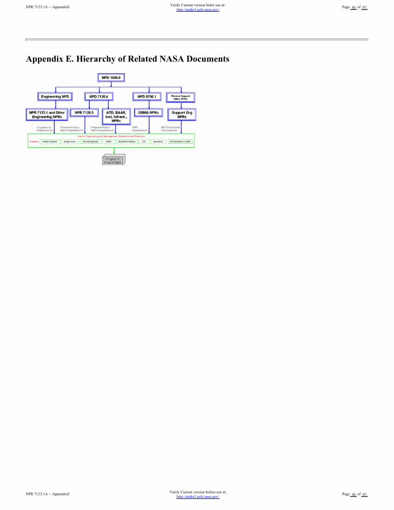
Appendix E. Hierarchy of Related NASA Documents
NPR 7123.1A -- AppendixEVerify Current version before use at:
http://nodis3.gsfc.nasa.gov/Page 50 of 97
NPR 7123.1A -- AppendixEVerify Current version befor use at:
http://nodis3.gsfc.nasa.gov/Page 50 of 97
Appendix F. Tailoring
F.1 Tailoring is the documentation and approval of the adaptation of the processes and approach to complying with requirements according to the purpose, complexity, and scope of aNASA program or project. Tailoring, including rationale for modifications, additions, or deletions should be approved by the DGA.
F.2 Each project following this SE NPR needs to tailor to the specific needs of a particular project, phase, or acquisition structure. Tasks that add unnecessary costs or data and any factorsthat do not add value to the project should be eliminated. Tailoring takes the form of modification or addition.
F.3 Tailoring specific tasks requires definition of the depth of detail, level of effort, and the data expected. Tailoring is performed to both breadth and depth based on the project and specificphase of the life cycle. "Tailoring in breadth" deals with factors that can include types and numbers of systems impacted by the development of a new subsystem, the numbers and types ofassessments, and numbers and types of reviews. "Tailoring in depth" involves decisions concerning the level of detail needed to generate and substantiate the requirements. The depth of theSE effort varies from project to project in relation to complexity, uncertainty, urgency, and the willingness to accept risk.
F.4 The objectives of the effort, the scope of the SE process, and the breadth and depth of application need to be considered. To assist in defining the depth of application and level of effort,the following should be evaluated as part of the tailoring process of this SE NPR:
a. The level of detail in system definition required from the in-house Government or contracted effort.
b. The directions and limitations of tasks including willingness to accept risk.
c. The scenarios and missions to be examined for each primary system function.
d. A set of measures of effectiveness.
e. Known constraints in areas where they exist but quantitative data is not available.
f. The technology database including identification of key technologies, performance, maturity, cost, risks, schedule, and any limiting criteria on the use of technologies.
g. The factors essential to system success, including those factors related to major risk areas (e.g., budget, resources, and schedule).
h. Technical demonstration and confirmation events that need to be conducted (including technical reviews).
i. The goals and constraints of the project.
j. The organizational and contractual requirements for SE processes.
k. The baseline SE process for the organization and tailoring guidelines.
l. Any cost targets and the acceptable level of risk.
F.5 The basic SE tailoring process can be applied to any development effort (including new developments, modifications, and product improvements) regardless of size or complexity.Attention to scope of the effort and level of output expected is essential. A revolutionary new system development, for example, in Formulation will not usually require formal configurationmanagement audits or formal change control mechanisms. However, conceptual exploration investigation of modifications to an existing developed system may need this type of activity.
F.6 The level of detail expected from the system products of the technical effort needs to be identified. This will determine the depth to which the SE process is executed. For example,functional analysis and synthesis are conducted to a sufficiently detailed depth to identify areas of technical risk based on the life-cycle phase or effort.
F.7 The term "sufficiently detailed" is determined based on the objectives of the project and can be characterized by the information content expected from the physical architecture.Throughout the life cycle, the level of detail may vary since the baseline system may be at one level of detail and product improvements or other modifications may be at a different level ofdetail. Note that level of detail needed from the technical effort to ensure adequacy of technical definition, design, and development is not synonymous with the level of detail expected formanagement control and reporting (e.g., cost performance reports).
F.8 The primary output of the SE tailoring process for a project is documented in the SEMP. The form of the SEMP will vary depending on the size, complexity and acceptable cost or risklevel of the project.
References
The following documents were used as reference materials in the development of this appendix:
a. Defense Acquisition University Systems Engineering Fundamentals. Ft. Belvoir, Virginia: Defense Acquisition University Press, December 2000.
b. International Council on Systems Engineering (INCOSE) Systems Engineering Guide.
NPR 7123.1A -- AppendixFVerify Current version before use at:
http://nodis3.gsfc.nasa.gov/Page 51 of 97
NPR 7123.1A -- AppendixFVerify Current version befor use at:
http://nodis3.gsfc.nasa.gov/Page 51 of 97
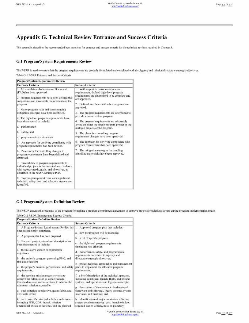
Appendix G. Technical Review Entrance and Success Criteria
This appendix describes the recommended best practices for entrance and success criteria for the technical reviews required in Chapter 5.
G.1 Program\System Requirements Review
The P/SRR is used to ensure that the program requirements are properly formulated and correlated with the Agency and mission directorate strategic objectives.
Table G-1 P/SRR Entrance and Success Criteria
Program/System Requirements Review
Entrance Criteria Success Criteria
1. A Formulation Authorization Document
(FAD) has been approved.
2. Program requirements have been defined that
support mission directorate requirements on the
program.
3. Major program risks and corresponding
mitigation strategies have been identified.
4. The high-level program requirements have
been documented to include:
a. performance,
b. safety, and
c. programmatic requirements.
5. An approach for verifying compliance with
program requirements has been defined.
6. Procedures for controlling changes to
program requirements have been defined and
approved.
7. Traceability of program requirements to
individual projects is documented in accordance
with Agency needs, goals, and objectives, as
described in the NASA Strategic Plan.
8. Top program/project risks with significant
technical, safety, cost, and schedule impacts are
identified.
1. With respect to mission and science
requirements, defined high-level program
requirements are determined to be complete and
are approved.
2. Defined interfaces with other programs are
approved.
3. The program requirements are determined to
provide a cost-effective program.
4. The program requirements are adequately
levied on either the single-program project or the
multiple projects of the program.
5. The plans for controlling program
requirement changes have been approved.
6. The approach for verifying compliance with
program requirements has been approved.
7. The mitigation strategies for handling
identified major risks have been approved.
G.2 Program/System Definition Review
The P/SDR ensures the readiness of the program for making a program commitment agreement to approve project formulation startups during program Implementation phase.
Table G-2 P/SDR Entrance and Success Criteria
Program/System Definition Review
Entrance Criteria Success Criteria
1. A Program/System Requirements Review has
been satisfactorily completed.
2. A program plan has been prepared.
3. For each project, a top-level description has
been documented to include:
a. the mission's science or exploration
objectives;
b. the project's category, governing PMC, and
risk classification;
c. the project's mission, performance, and safety
requirements;
d. the baseline mission success criteria to
achieve the full mission as conceived and
threshold mission success criteria to achieve the
minimum mission acceptable;
e. each criterion in objective, quantifiable, and
verifiable terms;
f. each project?s principal schedule milestones,
including PDR, CDR, launch, mission
operational critical milestones, and the planned
1. Approved program plan that includes:
a. how the program will be managed;
b. a list of specific projects;
c. the high-level program requirements
(including risk criteria);
d. performance, safety, and programmatic
requirements correlated to Agency and
directorate strategic objectives;
e. project technical approaches and management
plans to implement the allocated program
requirements;
f. a brief description of the technical approach,
including constituent launch, flight, and ground
systems, and operations and logistics concepts;
g. description of the systems to be developed
(hardware and software), legacy systems, system
interfaces, and facilities; and
h. identification of major constraints affecting
system development (e.g., cost, launch window,
required launch vehicle, mission planetary
NPR 7123.1A -- AppendixGVerify Current version before use at:
http://nodis3.gsfc.nasa.gov/Page 52 of 97
NPR 7123.1A -- AppendixGVerify Current version befor use at:
http://nodis3.gsfc.nasa.gov/Page 52 of 97
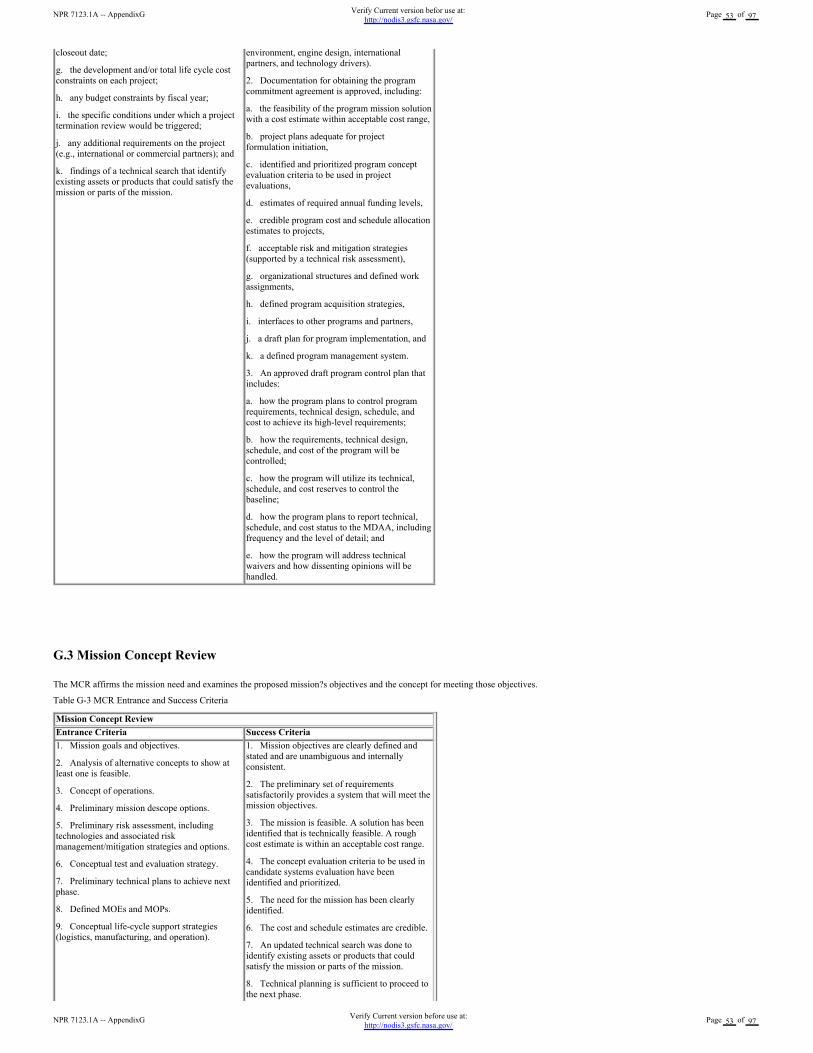
G.3 Mission Concept Review
The MCR affirms the mission need and examines the proposed mission?s objectives and the concept for meeting those objectives.
Table G-3 MCR Entrance and Success Criteria
Mission Concept Review
Entrance Criteria Success Criteria
1. Mission goals and objectives.
2. Analysis of alternative concepts to show at
least one is feasible.
3. Concept of operations.
4. Preliminary mission descope options.
5. Preliminary risk assessment, including
technologies and associated risk
management/mitigation strategies and options.
6. Conceptual test and evaluation strategy.
7. Preliminary technical plans to achieve next
phase.
8. Defined MOEs and MOPs.
9. Conceptual life-cycle support strategies
(logistics, manufacturing, and operation).
1. Mission objectives are clearly defined and
stated and are unambiguous and internally
consistent.
2. The preliminary set of requirements
satisfactorily provides a system that will meet the
mission objectives.
3. The mission is feasible. A solution has been
identified that is technically feasible. A rough
cost estimate is within an acceptable cost range.
4. The concept evaluation criteria to be used in
candidate systems evaluation have been
identified and prioritized.
5. The need for the mission has been clearly
identified.
6. The cost and schedule estimates are credible.
7. An updated technical search was done to
identify existing assets or products that could
satisfy the mission or parts of the mission.
8. Technical planning is sufficient to proceed to
the next phase.
closeout date;
g. the development and/or total life cycle cost
constraints on each project;
h. any budget constraints by fiscal year;
i. the specific conditions under which a project
termination review would be triggered;
j. any additional requirements on the project
(e.g., international or commercial partners); and
k. findings of a technical search that identify
existing assets or products that could satisfy the
mission or parts of the mission.
environment, engine design, international
partners, and technology drivers).
2. Documentation for obtaining the program
commitment agreement is approved, including:
a. the feasibility of the program mission solution
with a cost estimate within acceptable cost range,
b. project plans adequate for project
formulation initiation,
c. identified and prioritized program concept
evaluation criteria to be used in project
evaluations,
d. estimates of required annual funding levels,
e. credible program cost and schedule allocation
estimates to projects,
f. acceptable risk and mitigation strategies
(supported by a technical risk assessment),
g. organizational structures and defined work
assignments,
h. defined program acquisition strategies,
i. interfaces to other programs and partners,
j. a draft plan for program implementation, and
k. a defined program management system.
3. An approved draft program control plan that
includes:
a. how the program plans to control program
requirements, technical design, schedule, and
cost to achieve its high-level requirements;
b. how the requirements, technical design,
schedule, and cost of the program will be
controlled;
c. how the program will utilize its technical,
schedule, and cost reserves to control the
baseline;
d. how the program plans to report technical,
schedule, and cost status to the MDAA, including
frequency and the level of detail; and
e. how the program will address technical
waivers and how dissenting opinions will be
handled.
NPR 7123.1A -- AppendixGVerify Current version before use at:
http://nodis3.gsfc.nasa.gov/Page 53 of 97
NPR 7123.1A -- AppendixGVerify Current version befor use at:
http://nodis3.gsfc.nasa.gov/Page 53 of 97

9. Risk and mitigation strategies have been
identified and are acceptable based on technical
risk assessments.
G.4 System Requirements Review
The SRR examines the functional and performance requirements defined for the system and the preliminary program or project plan and ensures that the requirements and the selectedconcept will satisfy the mission
Table G-4 SRR Entrance and Success Criteria
System Requirements Review
Entrance Criteria Success Criteria
1. Successful completion of the MCR and
responses made to all MCR Requests for Actions
(RFAs) and Review Item Discrepancies (RIDs).
2. A preliminary SRR agenda, success criteria,
and charge to the board have been agreed to by
the technical team, project manager, and review
chair prior to the SRR.
3. The following technical products for
hardware and software system elements are
available to the cognizant participants prior to the
review:
a. system requirements document;
b. system software functionality description;
c. updated concept of operations;
d. updated mission requirements, if applicable;
e. baselined SEMP;
f. risk management plan;
g. preliminary system requirements allocation to
the next lower level system;
h. updated cost estimate;
i. Technology Development Maturity
Assessment Plan;
j. updated risk assessment and mitigations
(including PRA as applicable).
k. logistics documentation (e.g., preliminary
maintenance plan);
l. preliminary human rating plan, if applicable;
m. Software Development Plan (SDP);
n. system safety and mission assurance plan;
o. configuration management plan;
p. initial document tree;
q. verification and validation approach;
r. preliminary system safety analysis; and
s. other specialty disciplines, as required.
1. The project utilizes a sound process for the
allocation and control of requirements throughout
all levels, and a plan has been defined to
complete the definition activity within schedule
constraints.
2. Requirements definition is complete with
respect to top-level mission and science
requirements, and interfaces with external entities
and between major internal elements have been
defined.
3. Requirements allocation and flow down of
key driving requirements have been defined
down to subsystems.
4. Preliminary approaches have been
determined for how requirements will be verified
and validated down to the subsystem level.
5. Major risks have been identified and
technically assessed, and viable mitigation
strategies have been defined.
G.5 Mission Definition Review
The MDR examines the proposed requirements, the mission architecture, and the flow down to all functional elements of the mission to ensure that the overall concept is complete, feasible,and consistent with available resources.
Table G-5 MDR Entrance and Success Criteria
Mission Definition Review
Entrance Criteria Success Criteria
1. Successful completion of the SRR and
responses made to all SRR RFAs and RIDs.
2. A preliminary MDR agenda, success criteria,
and charge to the board have been agreed to by
the technical team, project manager, and review
chair prior to the MDR.
3. The following technical products for
hardware and software system elements are
available to the cognizant participants prior to the
review:
1. The resulting overall concept is reasonable,
feasible, complete, responsive to the mission
requirements, and is consistent with system
requirements and available resources (cost,
schedule, mass, and power).
2. System and subsystem design approaches and
operational concepts exist and are consistent with
the requirements set.
3. The requirements, design approaches, and
conceptual design will fulfill the mission needs
within the estimated costs.
NPR 7123.1A -- AppendixGVerify Current version before use at:
http://nodis3.gsfc.nasa.gov/Page 54 of 97
NPR 7123.1A -- AppendixGVerify Current version befor use at:
http://nodis3.gsfc.nasa.gov/Page 54 of 97
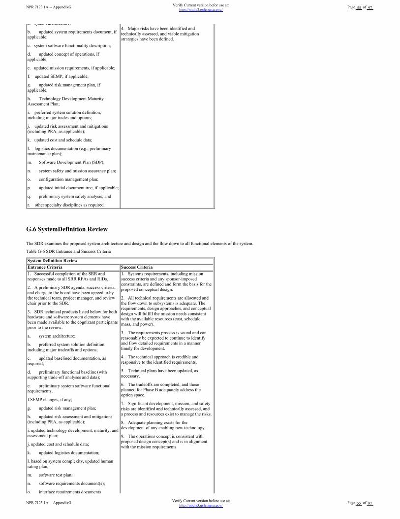
a. system architecture;
b. updated system requirements document, if
applicable;
c. system software functionality description;
d. updated concept of operations, if
applicable;
e. updated mission requirements, if applicable;
f. updated SEMP, if applicable;
g. updated risk management plan, if
applicable;
h. Technology Development Maturity
Assessment Plan;
i. preferred system solution definition,
including major trades and options;
j. updated risk assessment and mitigations
(including PRA, as applicable);
k. updated cost and schedule data;
l. logistics documentation (e.g., preliminary
maintenance plan);
m. Software Development Plan (SDP);
n. system safety and mission assurance plan;
o. configuration management plan;
p. updated initial document tree, if applicable;
q. preliminary system safety analysis; and
r. other specialty disciplines as required.
4. Major risks have been identified and
technically assessed, and viable mitigation
strategies have been defined.
G.6 SystemDefinition Review
The SDR examines the proposed system architecture and design and the flow down to all functional elements of the system.
Table G-6 SDR Entrance and Success Criteria
System Definition Review
Entrance Criteria Success Criteria
1. Successful completion of the SRR and
responses made to all SRR RFAs and RIDs.
2. A preliminary SDR agenda, success criteria,
and charge to the board have been agreed to by
the technical team, project manager, and review
chair prior to the SDR.
3. SDR technical products listed below for both
hardware and software system elements have
been made available to the cognizant participants
prior to the review:
a. system architecture;
b. preferred system solution definition
including major tradeoffs and options;
c. updated baselined documentation, as
required;
d. preliminary functional baseline (with
supporting trade-off analyses and data);
e. preliminary system software functional
requirements;
f.SEMP changes, if any;
g. updated risk management plan;
h. updated risk assessment and mitigations
(including PRA, as applicable);
i. updated technology development, maturity, and
assessment plan;
j. updated cost and schedule data;
k. updated logistics documentation;
l. based on system complexity, updated human
rating plan;
m. software test plan;
n. software requirements document(s);
o. interface requirements documents
1. Systems requirements, including mission
success criteria and any sponsor-imposed
constraints, are defined and form the basis for the
proposed conceptual design.
2. All technical requirements are allocated and
the flow down to subsystems is adequate. The
requirements, design approaches, and conceptual
design will fulfill the mission needs consistent
with the available resources (cost, schedule,
mass, and power).
3. The requirements process is sound and can
reasonably be expected to continue to identify
and flow detailed requirements in a manner
timely for development.
4. The technical approach is credible and
responsive to the identified requirements.
5. Technical plans have been updated, as
necessary.
6. The tradeoffs are completed, and those
planned for Phase B adequately address the
option space.
7. Significant development, mission, and safety
risks are identified and technically assessed, and
a process and resources exist to manage the risks.
8. Adequate planning exists for the
development of any enabling new technology.
9. The operations concept is consistent with
proposed design concept(s) and is in alignment
with the mission requirements.
NPR 7123.1A -- AppendixGVerify Current version before use at:
http://nodis3.gsfc.nasa.gov/Page 55 of 97
NPR 7123.1A -- AppendixGVerify Current version befor use at:
http://nodis3.gsfc.nasa.gov/Page 55 of 97
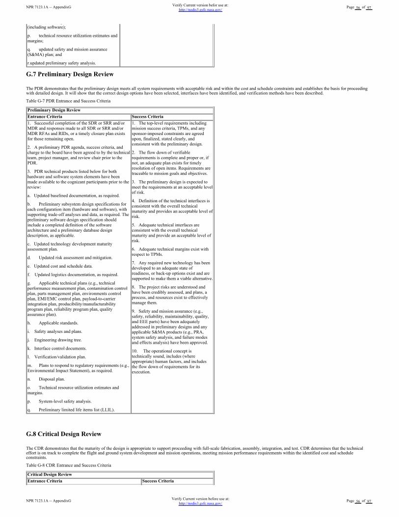
G.7 Preliminary Design Review
The PDR demonstrates that the preliminary design meets all system requirements with acceptable risk and within the cost and schedule constraints and establishes the basis for proceedingwith detailed design. It will show that the correct design options have been selected, interfaces have been identified, and verification methods have been described.
Table G-7 PDR Entrance and Success Criteria
Preliminary Design Review
Entrance Criteria Success Criteria
1. Successful completion of the SDR or SRR and/or
MDR and responses made to all SDR or SRR and/or
MDR RFAs and RIDs, or a timely closure plan exists
for those remaining open.
2. A preliminary PDR agenda, success criteria, and
charge to the board have been agreed to by the technical
team, project manager, and review chair prior to the
PDR.
3. PDR technical products listed below for both
hardware and software system elements have been
made available to the cognizant participants prior to the
review:
a. Updated baselined documentation, as required.
b. Preliminary subsystem design specifications for
each configuration item (hardware and software), with
supporting trade-off analyses and data, as required. The
preliminary software design specification should
include a completed definition of the software
architecture and a preliminary database design
description, as applicable.
c. Updated technology development maturity
assessment plan.
d. Updated risk assessment and mitigation.
e. Updated cost and schedule data.
f. Updated logistics documentation, as required.
g. Applicable technical plans (e.g., technical
performance measurement plan, contamination control
plan, parts management plan, environments control
plan, EMI/EMC control plan, payload-to-carrier
integration plan, producibility/manufacturability
program plan, reliability program plan, quality
assurance plan).
h. Applicable standards.
i. Safety analyses and plans.
j. Engineering drawing tree.
k. Interface control documents.
l. Verification/validation plan.
m. Plans to respond to regulatory requirements (e.g.,
Environmental Impact Statement), as required.
n. Disposal plan.
o. Technical resource utilization estimates and
margins.
p. System-level safety analysis.
q. Preliminary limited life items list (LLIL).
1. The top-level requirements including
mission success criteria, TPMs, and any
sponsor-imposed constraints are agreed
upon, finalized, stated clearly, and
consistent with the preliminary design.
2. The flow down of verifiable
requirements is complete and proper or, if
not, an adequate plan exists for timely
resolution of open items. Requirements are
traceable to mission goals and objectives.
3. The preliminary design is expected to
meet the requirements at an acceptable level
of risk.
4. Definition of the technical interfaces is
consistent with the overall technical
maturity and provides an acceptable level of
risk.
5. Adequate technical interfaces are
consistent with the overall technical
maturity and provide an acceptable level of
risk.
6. Adequate technical margins exist with
respect to TPMs.
7. Any required new technology has been
developed to an adequate state of
readiness, or back-up options exist and are
supported to make them a viable alternative.
8. The project risks are understood and
have been credibly assessed, and plans, a
process, and resources exist to effectively
manage them.
9. Safety and mission assurance (e.g.,
safety, reliability, maintainability, quality,
and EEE parts) have been adequately
addressed in preliminary designs and any
applicable S&MA products (e.g., PRA,
system safety analysis, and failure modes
and effects analysis) have been approved.
10. The operational concept is
technically sound, includes (where
appropriate) human factors, and includes
the flow down of requirements for its
execution.
G.8 Critical Design Review
The CDR demonstrates that the maturity of the design is appropriate to support proceeding with full-scale fabrication, assembly, integration, and test. CDR determines that the technicaleffort is on track to complete the flight and ground system development and mission operations, meeting mission performance requirements within the identified cost and scheduleconstraints.
Table G-8 CDR Entrance and Success Criteria
Critical Design Review
Entrance Criteria Success Criteria
o. interface requirements documents
(including software);
p. technical resource utilization estimates and
margins;
q. updated safety and mission assurance
(S&MA) plan; and
r.updated preliminary safety analysis.
NPR 7123.1A -- AppendixGVerify Current version before use at:
http://nodis3.gsfc.nasa.gov/Page 56 of 97
NPR 7123.1A -- AppendixGVerify Current version befor use at:
http://nodis3.gsfc.nasa.gov/Page 56 of 97
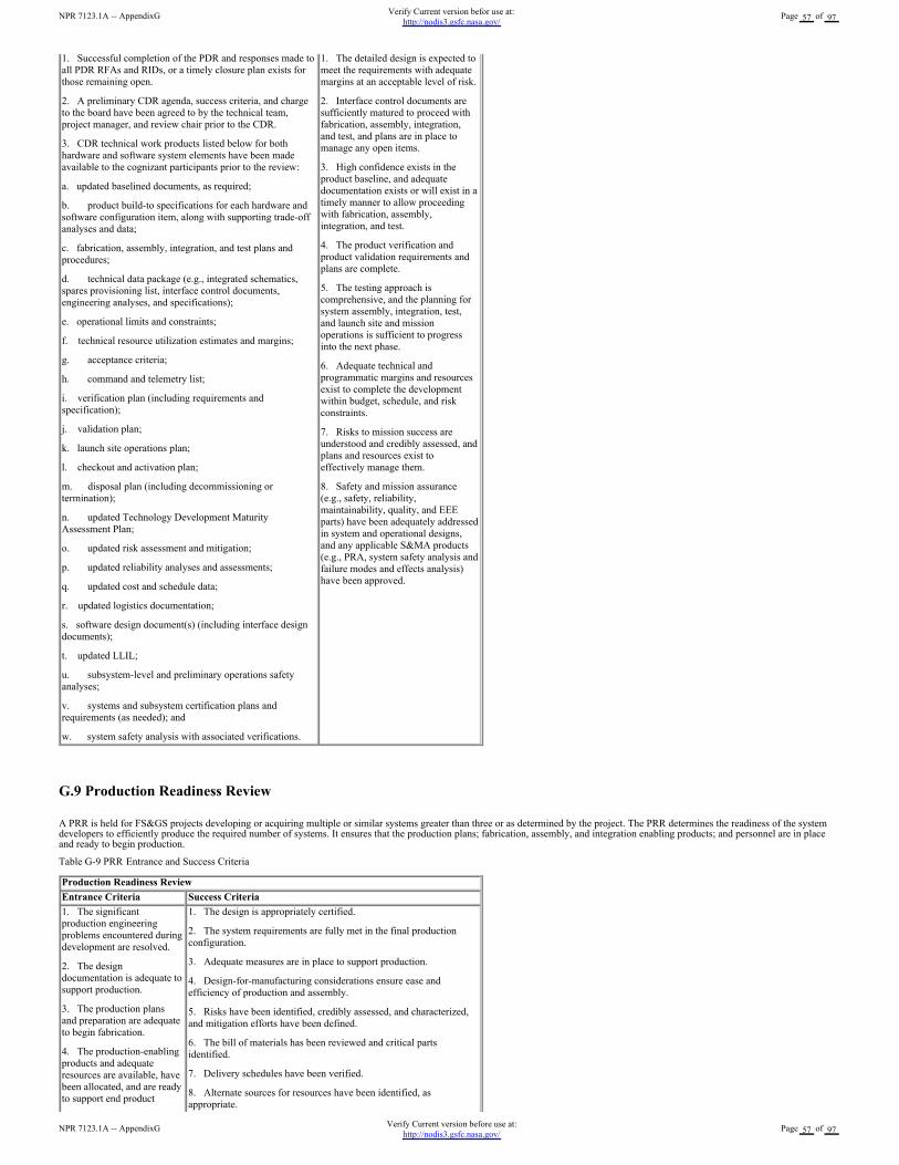
1. Successful completion of the PDR and responses made to
all PDR RFAs and RIDs, or a timely closure plan exists for
those remaining open.
2. A preliminary CDR agenda, success criteria, and charge
to the board have been agreed to by the technical team,
project manager, and review chair prior to the CDR.
3. CDR technical work products listed below for both
hardware and software system elements have been made
available to the cognizant participants prior to the review:
a. updated baselined documents, as required;
b. product build-to specifications for each hardware and
software configuration item, along with supporting trade-off
analyses and data;
c. fabrication, assembly, integration, and test plans and
procedures;
d. technical data package (e.g., integrated schematics,
spares provisioning list, interface control documents,
engineering analyses, and specifications);
e. operational limits and constraints;
f. technical resource utilization estimates and margins;
g. acceptance criteria;
h. command and telemetry list;
i. verification plan (including requirements and
specification);
j. validation plan;
k. launch site operations plan;
l. checkout and activation plan;
m. disposal plan (including decommissioning or
termination);
n. updated Technology Development Maturity
Assessment Plan;
o. updated risk assessment and mitigation;
p. updated reliability analyses and assessments;
q. updated cost and schedule data;
r. updated logistics documentation;
s. software design document(s) (including interface design
documents);
t. updated LLIL;
u. subsystem-level and preliminary operations safety
analyses;
v. systems and subsystem certification plans and
requirements (as needed); and
w. system safety analysis with associated verifications.
1. The detailed design is expected to
meet the requirements with adequate
margins at an acceptable level of risk.
2. Interface control documents are
sufficiently matured to proceed with
fabrication, assembly, integration,
and test, and plans are in place to
manage any open items.
3. High confidence exists in the
product baseline, and adequate
documentation exists or will exist in a
timely manner to allow proceeding
with fabrication, assembly,
integration, and test.
4. The product verification and
product validation requirements and
plans are complete.
5. The testing approach is
comprehensive, and the planning for
system assembly, integration, test,
and launch site and mission
operations is sufficient to progress
into the next phase.
6. Adequate technical and
programmatic margins and resources
exist to complete the development
within budget, schedule, and risk
constraints.
7. Risks to mission success are
understood and credibly assessed, and
plans and resources exist to
effectively manage them.
8. Safety and mission assurance
(e.g., safety, reliability,
maintainability, quality, and EEE
parts) have been adequately addressed
in system and operational designs,
and any applicable S&MA products
(e.g., PRA, system safety analysis and
failure modes and effects analysis)
have been approved.
G.9 Production Readiness Review
A PRR is held for FS&GS projects developing or acquiring multiple or similar systems greater than three or as determined by the project. The PRR determines the readiness of the systemdevelopers to efficiently produce the required number of systems. It ensures that the production plans; fabrication, assembly, and integration enabling products; and personnel are in placeand ready to begin production.
Table G-9 PRR Entrance and Success Criteria
Production Readiness Review
Entrance Criteria Success Criteria
1. The significant
production engineering
problems encountered during
development are resolved.
2. The design
documentation is adequate to
support production.
3. The production plans
and preparation are adequate
to begin fabrication.
4. The production-enabling
products and adequate
resources are available, have
been allocated, and are ready
to support end product
1. The design is appropriately certified.
2. The system requirements are fully met in the final production
configuration.
3. Adequate measures are in place to support production.
4. Design-for-manufacturing considerations ensure ease and
efficiency of production and assembly.
5. Risks have been identified, credibly assessed, and characterized,
and mitigation efforts have been defined.
6. The bill of materials has been reviewed and critical parts
identified.
7. Delivery schedules have been verified.
8. Alternate sources for resources have been identified, as
appropriate.
NPR 7123.1A -- AppendixGVerify Current version before use at:
http://nodis3.gsfc.nasa.gov/Page 57 of 97
NPR 7123.1A -- AppendixGVerify Current version befor use at:
http://nodis3.gsfc.nasa.gov/Page 57 of 97
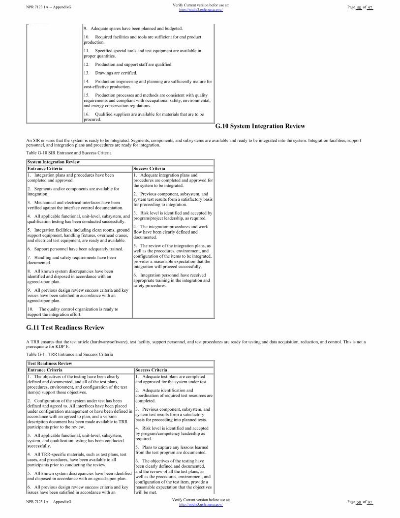
G.10 System Integration Review
An SIR ensures that the system is ready to be integrated. Segments, components, and subsystems are available and ready to be integrated into the system. Integration facilities, supportpersonnel, and integration plans and procedures are ready for integration.
Table G-10 SIR Entrance and Success Criteria
G.11 Test Readiness Review
A TRR ensures that the test article (hardware/software), test facility, support personnel, and test procedures are ready for testing and data acquisition, reduction, and control. This is not aprerequisite for KDP E.
Table G-11 TRR Entrance and Success Criteria
production.
9. Adequate spares have been planned and budgeted.
10. Required facilities and tools are sufficient for end product
production.
11. Specified special tools and test equipment are available in
proper quantities.
12. Production and support staff are qualified.
13. Drawings are certified.
14. Production engineering and planning are sufficiently mature for
cost-effective production.
15. Production processes and methods are consistent with quality
requirements and compliant with occupational safety, environmental,
and energy conservation regulations.
16. Qualified suppliers are available for materials that are to be
procured.
System Integration Review
Entrance Criteria Success Criteria
1. Integration plans and procedures have been
completed and approved.
2. Segments and/or components are available for
integration.
3. Mechanical and electrical interfaces have been
verified against the interface control documentation.
4. All applicable functional, unit-level, subsystem, and
qualification testing has been conducted successfully.
5. Integration facilities, including clean rooms, ground
support equipment, handling fixtures, overhead cranes,
and electrical test equipment, are ready and available.
6. Support personnel have been adequately trained.
7. Handling and safety requirements have been
documented.
8. All known system discrepancies have been
identified and disposed in accordance with an
agreed-upon plan.
9. All previous design review success criteria and key
issues have been satisfied in accordance with an
agreed-upon plan.
10. The quality control organization is ready to
support the integration effort.
1. Adequate integration plans and
procedures are completed and approved for
the system to be integrated.
2. Previous component, subsystem, and
system test results form a satisfactory basis
for proceeding to integration.
3. Risk level is identified and accepted by
program/project leadership, as required.
4. The integration procedures and work
flow have been clearly defined and
documented.
5. The review of the integration plans, as
well as the procedures, environment, and
configuration of the items to be integrated,
provides a reasonable expectation that the
integration will proceed successfully.
6. Integration personnel have received
appropriate training in the integration and
safety procedures.
Test Readiness Review
Entrance Criteria Success Criteria
1. The objectives of the testing have been clearly
defined and documented, and all of the test plans,
procedures, environment, and configuration of the test
item(s) support those objectives.
2. Configuration of the system under test has been
defined and agreed to. All interfaces have been placed
under configuration management or have been defined in
accordance with an agreed to plan, and a version
description document has been made available to TRR
participants prior to the review.
3. All applicable functional, unit-level, subsystem,
system, and qualification testing has been conducted
successfully.
4. All TRR-specific materials, such as test plans, test
cases, and procedures, have been available to all
participants prior to conducting the review.
5. All known system discrepancies have been identified
and disposed in accordance with an agreed-upon plan.
6. All previous design review success criteria and key
issues have been satisfied in accordance with an
1. Adequate test plans are completed
and approved for the system under test.
2. Adequate identification and
coordination of required test resources are
completed.
3. Previous component, subsystem, and
system test results form a satisfactory
basis for proceeding into planned tests.
4. Risk level is identified and accepted
by program/competency leadership as
required.
5. Plans to capture any lessons learned
from the test program are documented.
6. The objectives of the testing have
been clearly defined and documented,
and the review of all the test plans, as
well as the procedures, environment, and
configuration of the test item, provide a
reasonable expectation that the objectives
will be met.
NPR 7123.1A -- AppendixGVerify Current version before use at:
http://nodis3.gsfc.nasa.gov/Page 58 of 97
NPR 7123.1A -- AppendixGVerify Current version befor use at:
http://nodis3.gsfc.nasa.gov/Page 58 of 97
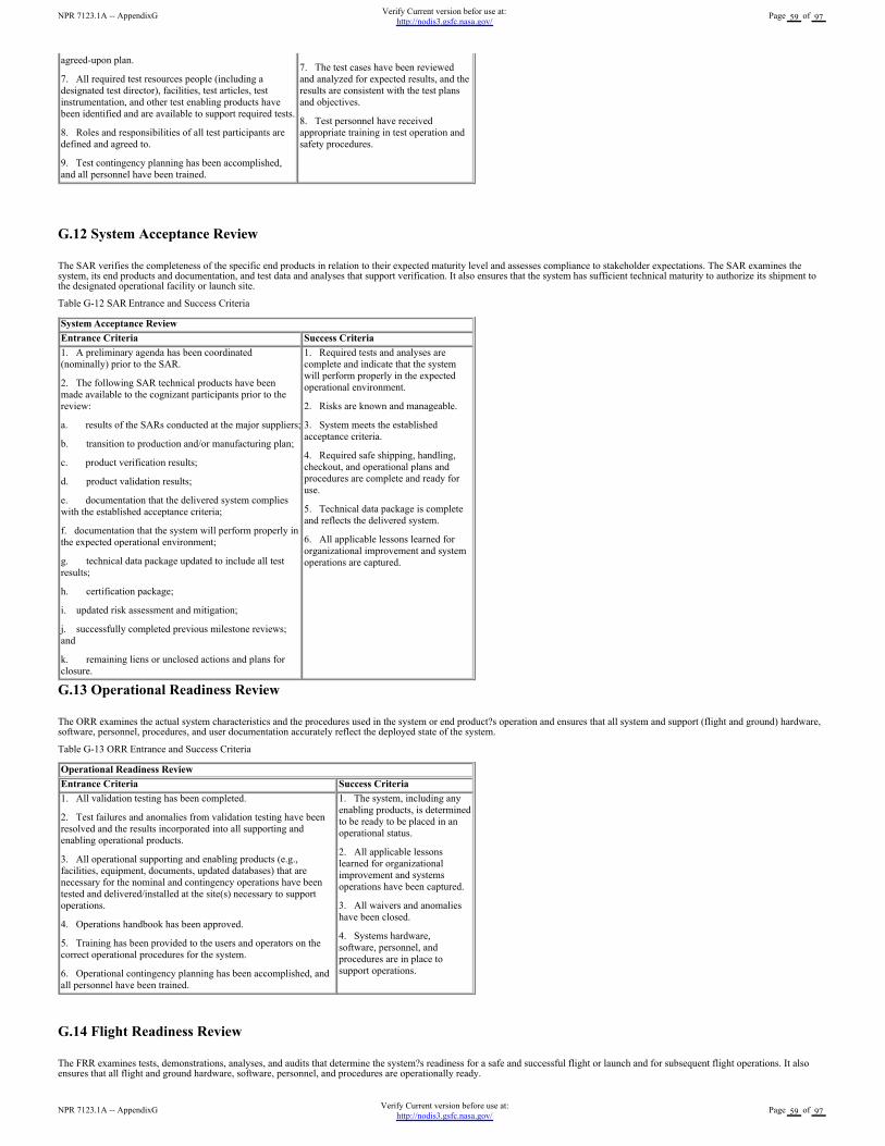
G.12 System Acceptance Review
The SAR verifies the completeness of the specific end products in relation to their expected maturity level and assesses compliance to stakeholder expectations. The SAR examines thesystem, its end products and documentation, and test data and analyses that support verification. It also ensures that the system has sufficient technical maturity to authorize its shipment tothe designated operational facility or launch site.
Table G-12 SAR Entrance and Success Criteria
G.13 Operational Readiness Review
The ORR examines the actual system characteristics and the procedures used in the system or end product?s operation and ensures that all system and support (flight and ground) hardware,software, personnel, procedures, and user documentation accurately reflect the deployed state of the system.
Table G-13 ORR Entrance and Success Criteria
G.14 Flight Readiness Review
The FRR examines tests, demonstrations, analyses, and audits that determine the system?s readiness for a safe and successful flight or launch and for subsequent flight operations. It alsoensures that all flight and ground hardware, software, personnel, and procedures are operationally ready.
Table G-14 FRR Entrance and Success Criteria
issues have been satisfied in accordance with an
agreed-upon plan.
7. All required test resources people (including a
designated test director), facilities, test articles, test
instrumentation, and other test enabling products have
been identified and are available to support required tests.
8. Roles and responsibilities of all test participants are
defined and agreed to.
9. Test contingency planning has been accomplished,
and all personnel have been trained.
will be met.
7. The test cases have been reviewed
and analyzed for expected results, and the
results are consistent with the test plans
and objectives.
8. Test personnel have received
appropriate training in test operation and
safety procedures.
System Acceptance Review
Entrance Criteria Success Criteria
1. A preliminary agenda has been coordinated
(nominally) prior to the SAR.
2. The following SAR technical products have been
made available to the cognizant participants prior to the
review:
a. results of the SARs conducted at the major suppliers;
b. transition to production and/or manufacturing plan;
c. product verification results;
d. product validation results;
e. documentation that the delivered system complies
with the established acceptance criteria;
f. documentation that the system will perform properly in
the expected operational environment;
g. technical data package updated to include all test
results;
h. certification package;
i. updated risk assessment and mitigation;
j. successfully completed previous milestone reviews;
and
k. remaining liens or unclosed actions and plans for
closure.
1. Required tests and analyses are
complete and indicate that the system
will perform properly in the expected
operational environment.
2. Risks are known and manageable.
3. System meets the established
acceptance criteria.
4. Required safe shipping, handling,
checkout, and operational plans and
procedures are complete and ready for
use.
5. Technical data package is complete
and reflects the delivered system.
6. All applicable lessons learned for
organizational improvement and system
operations are captured.
Operational Readiness Review
Entrance Criteria Success Criteria
1. All validation testing has been completed.
2. Test failures and anomalies from validation testing have been
resolved and the results incorporated into all supporting and
enabling operational products.
3. All operational supporting and enabling products (e.g.,
facilities, equipment, documents, updated databases) that are
necessary for the nominal and contingency operations have been
tested and delivered/installed at the site(s) necessary to support
operations.
4. Operations handbook has been approved.
5. Training has been provided to the users and operators on the
correct operational procedures for the system.
6. Operational contingency planning has been accomplished, and
all personnel have been trained.
1. The system, including any
enabling products, is determined
to be ready to be placed in an
operational status.
2. All applicable lessons
learned for organizational
improvement and systems
operations have been captured.
3. All waivers and anomalies
have been closed.
4. Systems hardware,
software, personnel, and
procedures are in place to
support operations.
NPR 7123.1A -- AppendixGVerify Current version before use at:
http://nodis3.gsfc.nasa.gov/Page 59 of 97
NPR 7123.1A -- AppendixGVerify Current version befor use at:
http://nodis3.gsfc.nasa.gov/Page 59 of 97
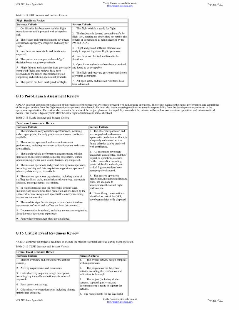
Table G-14 FRR Entrance and Success Criteria
G.15 Post-Launch Assessment Review
A PLAR is a post-deployment evaluation of the readiness of the spacecraft systems to proceed with full, routine operations. The review evaluates the status, performance, and capabilitiesof the project evident from the flight operations experience since launch. This can also mean assessing readiness to transfer responsibility from the development organization to theoperations organization. The review also evaluates the status of the project plans and the capability to conduct the mission with emphasis on near-term operations and mission-criticalevents. This review is typically held after the early flight operations and initial checkout.
Table G-15 PLAR Entrance and Success Criteria
Post-Launch Assessment Review
Entrance Criteria Success Criteria
1. The launch and early operations performance, including
(when appropriate) the early propulsive maneuver results, are
available.
2. The observed spacecraft and science instrument
performance, including instrument calibration plans and status,
are available.
3. The launch vehicle performance assessment and mission
implications, including launch sequence assessment, launch
operations experience with lessons learned, are completed.
4. The mission operations and ground data system experience,
including tracking and data acquisition support and spacecraft
telemetry data analysis, is available.
5. The mission operations organization, including status of
staffing, facilities, tools, and mission software (e.g., spacecraft
analysis, and sequencing), is available.
6. In-flight anomalies and the responsive actions taken,
including any autonomous fault protection actions taken by the
spacecraft or any unexplained spacecraft telemetry, including
alarms, are documented.
7. The need for significant changes to procedures, interface
agreements, software, and staffing has been documented.
8. Documentation is updated, including any updates originating
from the early operations experience.
9. Future development/test plans are developed.
1. The observed spacecraft and
science payload performance
agrees with prediction, or if not, is
adequately understood so that
future behavior can be predicted
with confidence.
2. All anomalies have been
adequately documented, and their
impact on operations assessed.
Further, anomalies impacting
spacecraft health and safety or
critical flight operations have
been properly disposed.
3. The mission operations
capabilities, including staffing and
plans, are adequate to
accommodate the actual flight
performance.
4. Liens, if any, on operations,
identified as part of the ORR,
have been satisfactorily disposed.
G.16 Critical Event Readiness Review
A CERR confirms the project?s readiness to execute the mission?s critical activities during flight operation.
Table G-16 CERR Entrance and Success Criteria
Critical Event Readiness Review
Entrance Criteria Success Criteria
1. Mission overview and context for the critical
event(s).
2. Activity requirements and constraints.
3. Critical activity sequence design description
including key tradeoffs and rationale for selected
approach.
4. Fault protection strategy.
5. Critical activity operations plan including planned
uplinks and criticality.
1. The critical activity design complies
with requirements.
2. The preparation for the critical
activity, including the verification and
validation, is thorough.
3. The project (including all the
systems, supporting services, and
documentation) is ready to support the
activity.
4. The requirements for the successful
Flight Readiness Review
Entrance Criteria Success Criteria
1. Certification has been received that flight
operations can safely proceed with acceptable
risk.
2. The system and support elements have been
confirmed as properly configured and ready for
flight.
3. Interfaces are compatible and function as
expected.
4. The system state supports a launch "go"
decision based on go/no-go criteria.
5. Flight failures and anomalies from previously
completed flights and reviews have been
resolved and the results incorporated into all
supporting and enabling operational products.
6. The system has been configured for flight.
1. The flight vehicle is ready for flight.
2. The hardware is deemed acceptably safe for
flight (i.e., meeting the established acceptable risk
criteria or documented as being accepted by the
PM and DGA).
3. Flight and ground software elements are
ready to support flight and flight operations.
4. Interfaces are checked and found to be
functional.
5. Open items and waivers have been examined
and found to be acceptable.
6. The flight and recovery environmental factors
are within constraints.
7. All open safety and mission risk items have
been addressed.
NPR 7123.1A -- AppendixGVerify Current version before use at:
http://nodis3.gsfc.nasa.gov/Page 60 of 97
NPR 7123.1A -- AppendixGVerify Current version befor use at:
http://nodis3.gsfc.nasa.gov/Page 60 of 97
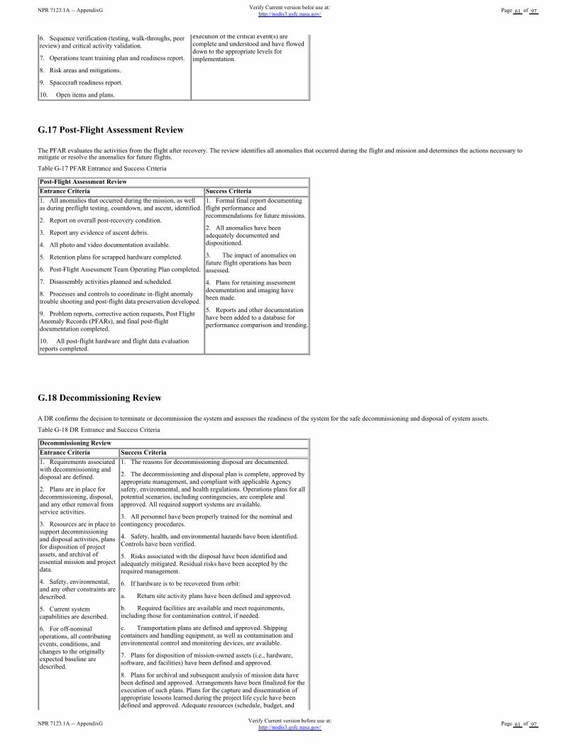
6. Sequence verification (testing, walk-throughs, peer
review) and critical activity validation.
7. Operations team training plan and readiness report.
8. Risk areas and mitigations.
9. Spacecraft readiness report.
10. Open items and plans.
execution of the critical event(s) are
complete and understood and have flowed
down to the appropriate levels for
implementation.
G.17 Post-Flight Assessment Review
The PFAR evaluates the activities from the flight after recovery. The review identifies all anomalies that occurred during the flight and mission and determines the actions necessary tomitigate or resolve the anomalies for future flights.
Table G-17 PFAR Entrance and Success Criteria
G.18 Decommissioning Review
A DR confirms the decision to terminate or decommission the system and assesses the readiness of the system for the safe decommissioning and disposal of system assets.
Table G-18 DR Entrance and Success Criteria
Post-Flight Assessment Review
Entrance Criteria Success Criteria
1. All anomalies that occurred during the mission, as well
as during preflight testing, countdown, and ascent, identified.
2. Report on overall post-recovery condition.
3. Report any evidence of ascent debris.
4. All photo and video documentation available.
5. Retention plans for scrapped hardware completed.
6. Post-Flight Assessment Team Operating Plan completed.
7. Disassembly activities planned and scheduled.
8. Processes and controls to coordinate in-flight anomaly
trouble shooting and post-flight data preservation developed.
9. Problem reports, corrective action requests, Post Flight
Anomaly Records (PFARs), and final post-flight
documentation completed.
10. All post-flight hardware and flight data evaluation
reports completed.
1. Formal final report documenting
flight performance and
recommendations for future missions.
2. All anomalies have been
adequately documented and
dispositioned.
3. The impact of anomalies on
future flight operations has been
assessed.
4. Plans for retaining assessment
documentation and imaging have
been made.
5. Reports and other documentation
have been added to a database for
performance comparison and trending.
Decommissioning Review
Entrance Criteria Success Criteria
1. Requirements associated
with decommissioning and
disposal are defined.
2. Plans are in place for
decommissioning, disposal,
and any other removal from
service activities.
3. Resources are in place to
support decommissioning
and disposal activities, plans
for disposition of project
assets, and archival of
essential mission and project
data.
4. Safety, environmental,
and any other constraints are
described.
5. Current system
capabilities are described.
6. For off-nominal
operations, all contributing
events, conditions, and
changes to the originally
expected baseline are
described.
1. The reasons for decommissioning disposal are documented.
2. The decommissioning and disposal plan is complete, approved by
appropriate management, and compliant with applicable Agency
safety, environmental, and health regulations. Operations plans for all
potential scenarios, including contingencies, are complete and
approved. All required support systems are available.
3. All personnel have been properly trained for the nominal and
contingency procedures.
4. Safety, health, and environmental hazards have been identified.
Controls have been verified.
5. Risks associated with the disposal have been identified and
adequately mitigated. Residual risks have been accepted by the
required management.
6. If hardware is to be recovered from orbit:
a. Return site activity plans have been defined and approved.
b. Required facilities are available and meet requirements,
including those for contamination control, if needed.
c. Transportation plans are defined and approved. Shipping
containers and handling equipment, as well as contamination and
environmental control and monitoring devices, are available.
7. Plans for disposition of mission-owned assets (i.e., hardware,
software, and facilities) have been defined and approved.
8. Plans for archival and subsequent analysis of mission data have
been defined and approved. Arrangements have been finalized for the
execution of such plans. Plans for the capture and dissemination of
appropriate lessons learned during the project life cycle have been
defined and approved. Adequate resources (schedule, budget, and
NPR 7123.1A -- AppendixGVerify Current version before use at:
http://nodis3.gsfc.nasa.gov/Page 61 of 97
NPR 7123.1A -- AppendixGVerify Current version befor use at:
http://nodis3.gsfc.nasa.gov/Page 61 of 97
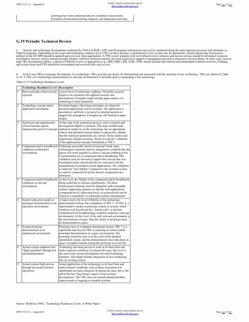
G.19 Periodic Technical Review
a. Science and technology development conducted by NASA in BAR, ATD, and IP programs and projects may not be conducted along the same rigorous processes and schedules asFS&GS programs. Depending on the scope and technology readiness level (TRL) of these projects, a streamlined review system may be appropriate. Sound engineering of processesdefined in this SE NPR should be applied and reviewed, when appropriate. A PTR review schedule with well defined review entrance and success criteria should be developed in projectformulation. Success criteria should ascertain whether sufficient technical maturity has been achieved to support a management decision to proceed to the next phase. In some cases, such ashigh TRL development efforts, a subset of FS&GS reviews is appropriate (e.g., SRR, PDR, CDR, SAR). PTRs should include both internal and independent external reviewers. Findingsand actions from each PTR should be disseminated and resolved after each review.
b. NASA uses TRLs to measure the maturity of a technology. TRLs provide one metric for determining risk associated with the insertion of new technology. TRLs are shown in TableG-19. A TRL of 6 (technology demonstrated in a relevant environment) is desirable prior to integrating a new technology.
Table G-19 Technology Readiness Levels
Source: Mankins (1995), "Technology Readiness Levels: A White Paper."
staffing) have been identified and are available to successfully
complete all decommissioning, disposal, and disposition activities.
Technology Readiness Level Description
1 Basic principles observed and
reported.
Lowest level of technology readiness. Scientific research
begins to be translated into applied research and
development. Examples might include paper studies of a
technology?s basic properties.
2 Technology concept and/or
application formulated.
Invention begins. Once basic principles are observed,
practical applications can be invented. The application is
speculative, and there is no proof or detailed analysis to
support the assumption. Examples are still limited to paper
studies.
3 Analytical and experimental
critical function and/or
characteristic proof of concept.
At this step in the maturation process, active research and
development (R&D) is initiated. This must include both
analytical studies to set the technology into an appropriate
context and laboratory-based studies to physically validate
that the analytical predictions are correct. These studies and
experiments should constitute "proof-of-concept" validation
of the applications/concepts formulated at TRL 2.
4 Component and/or breadboard
validation in laboratory
environment.
Following successful "proof-of-concept" work, basic
technological elements must be integrated to establish that the
pieces will work together to achieve concept-enabling levels
of performance for a component and/or breadboard. This
validation must be devised to support the concept that was
formulated earlier and should also be consistent with the
requirements of potential system applications. The validation
is relatively "low-fidelity" compared to the eventual system:
it could be composed of ad hoc discrete components in a
laboratory.
5 Component and/or breadboard
validation in relevant
environment.
At this level, the fidelity of the component and/or breadboard
being tested has to increase significantly. The basic
technological elements must be integrated with reasonably
realistic supporting elements so that the total applications
(component-level, subsystem-level, or system-level) can be
tested in a "simulated" or somewhat realistic environment.
6 System/subsystem model or
prototype demonstration in an
operation environment.
A major step in the level of fidelity of the technology
demonstration follows the completion of TRL 5. At TRL 6, a
representative model or prototype system or system, which
would go well beyond ad hoc, "patch-cord," or discrete
component level breadboarding, would be tested in a relevant
environment. At this level, if the only relevant environment is
the environment of space, then the model or prototype must
be demonstrated in space.
7 System prototype
demonstration in an
operational environment.
Prototype near or at planned operational system. TRL 7 is a
significant step beyond TRL 6, requiring an actual system
prototype demonstration in a space environment. The
prototype should be near or at the scale of the planned
operational system, and the demonstration must take place in
space. Examples include testing the prototype in a test bed.
8 Actual system competed and
"flight qualified" through test
and demonstration.
Technology has been proven to work in its final form and
under expected conditions. In almost all cases, this level is
the end of true system development for most technology
elements. This might include integration of new technology
into an existing system.
9 Actual system flight proven
through successful mission
operations
Actual application of the technology in its final form and
under mission conditions, such as those encountered in
operational test and evaluation. In almost all cases, this is the
end of the last "bug fixing" aspects of true system
development. This TRL does not include planned product
improvement of ongoing or reusable systems.
NPR 7123.1A -- AppendixGVerify Current version before use at:
http://nodis3.gsfc.nasa.gov/Page 62 of 97
NPR 7123.1A -- AppendixGVerify Current version befor use at:
http://nodis3.gsfc.nasa.gov/Page 62 of 97
G.20 Technical Peer Reviews
a. Peer reviews provide the technical insight essential to ensure product and process quality. Peer reviews are focused, in-depth technical reviews that support the evolving design anddevelopment of a product, including critical documentation or data packages. They are often, but not always, held as supporting reviews for technical reviews such as PDR and CDR. Apurpose of the peer review is to add value and reduce risk through expert knowledge, infusion, confirmation of approach, identification of defects, and specific suggestions for productimprovements.
b. The results of the engineering peer reviews (EPRs) comprise a key element of the review process. The results and issues that surface during these reviews are documented andreported at the appropriate next higher element level.
c. The peer reviewers should be selected from outside the project, but they should have a similar technical background, and they should be selected for their skill and experience. Peerreviewers should be concerned with only the technical integrity and quality of the product. Peer reviews should be kept simple and informal. They should concentrate on a review of thedocumentation and minimize viewgraph presentations. A round-table format rather than a stand-up presentation is preferred. The peer reviews should give the full technical picture of itemsbeing reviewed.
d. Technical depth should be established at a level that allows the review team to gain insight into the technical risks. Rules should be established to ensure consistency in the peer reviewprocess. At the conclusion of the review, a report on the findings and actions must be distributed.
e. Peer reviews must be part of the contract for those projects where systems engineering is done out-of-house.
NPR 7123.1A -- AppendixGVerify Current version before use at:
http://nodis3.gsfc.nasa.gov/Page 63 of 97
NPR 7123.1A -- AppendixGVerify Current version befor use at:
http://nodis3.gsfc.nasa.gov/Page 63 of 97
Appendix H. Templates
H-1 Sample SE NPR Implementation Plan Template
SE NPR Implementation Plan
<Center Name>
Revision: <enter rev number>
<enter date>
National Aeronautics and Space Administration
SE NPR Implementation Plan
<Center>
<Date>
Prepared by:
NPR 7123.1A -- AppendixHVerify Current version before use at:
http://nodis3.gsfc.nasa.gov/Page 64 of 97
NPR 7123.1A -- AppendixHVerify Current version befor use at:
http://nodis3.gsfc.nasa.gov/Page 64 of 97
Prepared by:
Name Date
Approved by:
Name
Center EMB Member
Date
Name
Office of Chief Engineer
Date
Change Record
Rev. Date Originator Approvals Description
Table of Contents
1.0 Introduction
1.1 purpose
1.2 Scope
1.3 Background
1.4 Designated governing Authority
2.0 Reference Documents
3.0 Compliance with SE NPR
3.1 Description of Center Compliance Methodology
3.2 Compliance Matrix
3.3 Plan to close gaps
4.0 Other
Appendix A Acronyms
Appendix B Glossary
NPR 7123.1A -- AppendixHVerify Current version before use at:
http://nodis3.gsfc.nasa.gov/Page 65 of 97
NPR 7123.1A -- AppendixHVerify Current version befor use at:
http://nodis3.gsfc.nasa.gov/Page 65 of 97
Table of Figures
Table of Tables
Table 3-1 SE NPR Compliance Matrix
1.0 Introduction
1.1 purpose
This document presents the organization?s plan to implement the requirements of the System Engineering (SE) NPR.
1.2 Scope
The scope of this document contains the plan for demonstrating compliance with the SE NPR requirements.
1.3 Background
Describe basic product lines for the Center and the scope of application of NPR requirements.
1.4 Designated Governing Authority
This section describes the criteria or methodology that the Center will use to determine who the designated governing authority (DGA) will be for various classes or categories of projectsperformed at the Center. One philosophy might be, for example, for projects under $10 million, the DGA will be at the division level.
2.0 Reference Documents
Enter such documents as existing Center requirement documents and work instructions that reflect implementation of the requirements of the NPR.
3.0 Compliance with SE NPR
3.1 Description of Center Compliance Methodology
This section would include general textual descriptions on how the organization will approach compliance with the requirements in the SE NPR.
Definition of the population that these requirements apply to and how they will be trained at the Center would also be included in this section.
Estimates of the cost to implement these requirements may also be included in this section.
3.2 Compliance Matrix
Table 3-1 provides the cross-reference of the SE NPR requirements with Center documentation.
NPR 7123.1A -- AppendixHVerify Current version before use at:
http://nodis3.gsfc.nasa.gov/Page 66 of 97
NPR 7123.1A -- AppendixHVerify Current version befor use at:
http://nodis3.gsfc.nasa.gov/Page 66 of 97
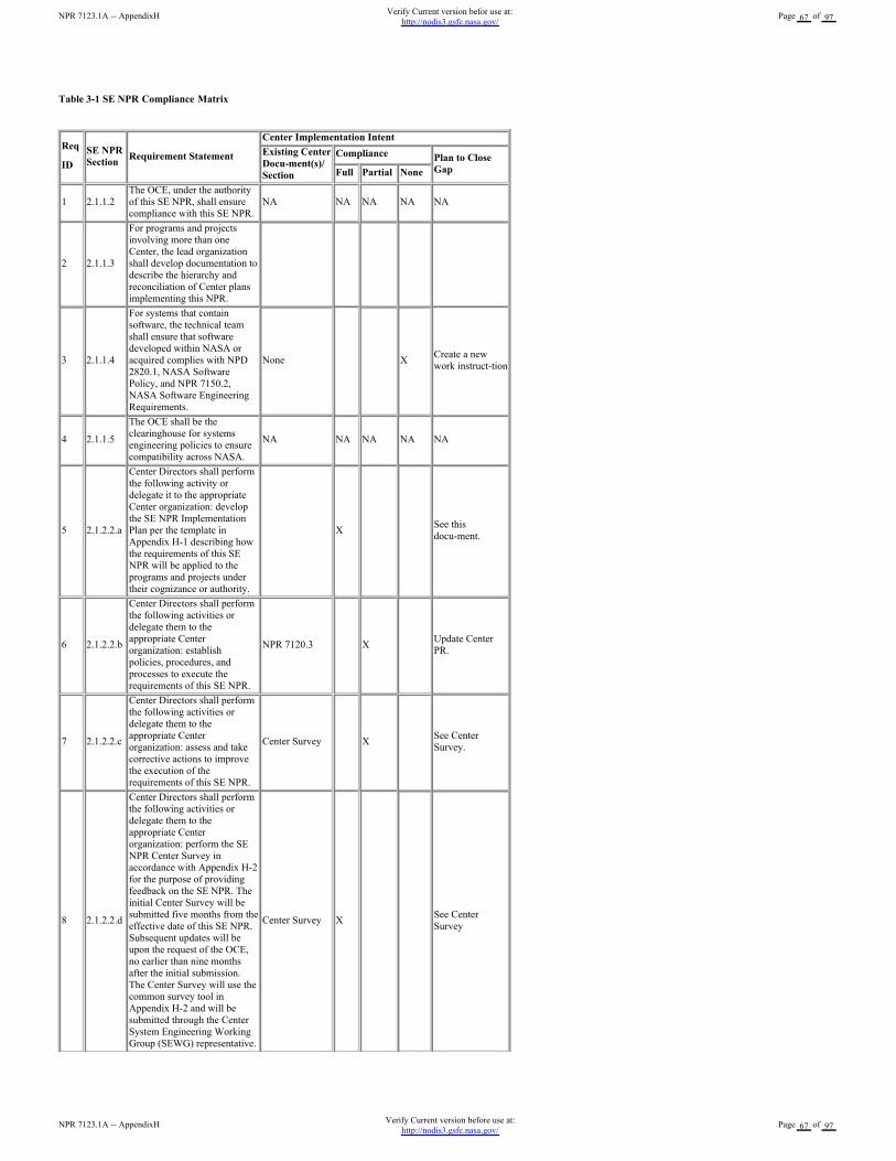
Table 3-1 SE NPR Compliance Matrix
Req
ID
SE NPR
SectionRequirement Statement
Center Implementation Intent
Existing Center
Docu-ment(s)/
Section
Compliance Plan to Close
GapFull Partial None
1 2.1.1.2
The OCE, under the authority
of this SE NPR, shall ensure
compliance with this SE NPR.
NA NA NA NA NA
2 2.1.1.3
For programs and projects
involving more than one
Center, the lead organization
shall develop documentation to
describe the hierarchy and
reconciliation of Center plans
implementing this NPR.
3 2.1.1.4
For systems that contain
software, the technical team
shall ensure that software
developed within NASA or
acquired complies with NPD
2820.1, NASA Software
Policy, and NPR 7150.2,
NASA Software Engineering
Requirements.
None XCreate a new
work instruct-tion
4 2.1.1.5
The OCE shall be the
clearinghouse for systems
engineering policies to ensure
compatibility across NASA.
NA NA NA NA NA
5 2.1.2.2.a
Center Directors shall perform
the following activity or
delegate it to the appropriate
Center organization: develop
the SE NPR Implementation
Plan per the template in
Appendix H-1 describing how
the requirements of this SE
NPR will be applied to the
programs and projects under
their cognizance or authority.
X See this
docu-ment.
6 2.1.2.2.b
Center Directors shall perform
the following activities or
delegate them to the
appropriate Center
organization: establish
policies, procedures, and
processes to execute the
requirements of this SE NPR.
NPR 7120.3 X Update Center
PR.
7 2.1.2.2.c
Center Directors shall perform
the following activities or
delegate them to the
appropriate Center
organization: assess and take
corrective actions to improve
the execution of the
requirements of this SE NPR.
Center Survey X See Center
Survey.
8 2.1.2.2.d
Center Directors shall perform
the following activities or
delegate them to the
appropriate Center
organization: perform the SE
NPR Center Survey in
accordance with Appendix H-2
for the purpose of providing
feedback on the SE NPR. The
initial Center Survey will be
submitted five months from the
effective date of this SE NPR.
Subsequent updates will be
upon the request of the OCE,
no earlier than nine months
after the initial submission.
The Center Survey will use the
common survey tool in
Appendix H-2 and will be
submitted through the Center
System Engineering Working
Group (SEWG) representative.
Center Survey X See Center
Survey
NPR 7123.1A -- AppendixHVerify Current version before use at:
http://nodis3.gsfc.nasa.gov/Page 67 of 97
NPR 7123.1A -- AppendixHVerify Current version befor use at:
http://nodis3.gsfc.nasa.gov/Page 67 of 97
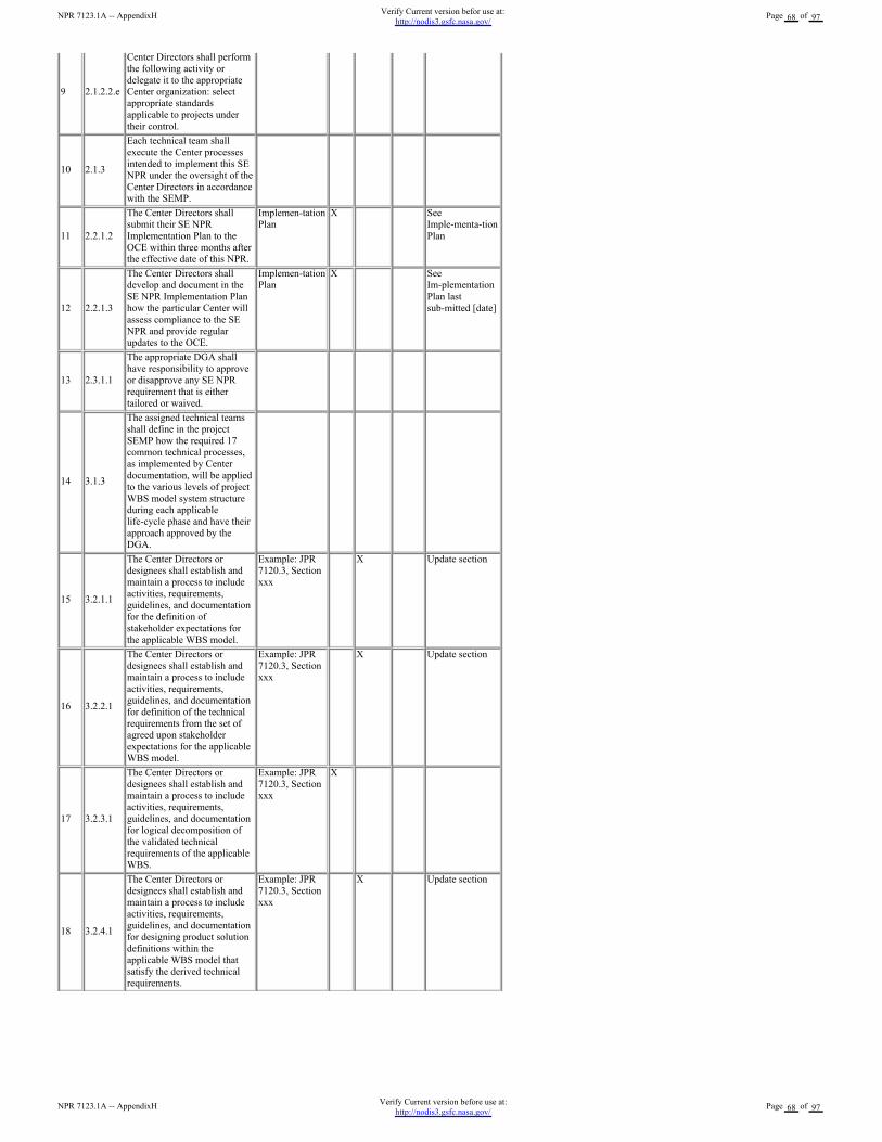
9 2.1.2.2.e
Center Directors shall perform
the following activity or
delegate it to the appropriate
Center organization: select
appropriate standards
applicable to projects under
their control.
10 2.1.3
Each technical team shall
execute the Center processes
intended to implement this SE
NPR under the oversight of the
Center Directors in accordance
with the SEMP.
11 2.2.1.2
The Center Directors shall
submit their SE NPR
Implementation Plan to the
OCE within three months after
the effective date of this NPR.
Implemen-tation
Plan
X See
Imple-menta-tion
Plan
12 2.2.1.3
The Center Directors shall
develop and document in the
SE NPR Implementation Plan
how the particular Center will
assess compliance to the SE
NPR and provide regular
updates to the OCE.
Implemen-tation
Plan
X See
Im-plementation
Plan last
sub-mitted [date]
13 2.3.1.1
The appropriate DGA shall
have responsibility to approve
or disapprove any SE NPR
requirement that is either
tailored or waived.
14 3.1.3
The assigned technical teams
shall define in the project
SEMP how the required 17
common technical processes,
as implemented by Center
documentation, will be applied
to the various levels of project
WBS model system structure
during each applicable
life-cycle phase and have their
approach approved by the
DGA.
15 3.2.1.1
The Center Directors or
designees shall establish and
maintain a process to include
activities, requirements,
guidelines, and documentation
for the definition of
stakeholder expectations for
the applicable WBS model.
Example: JPR
7120.3, Section
xxx
X Update section
16 3.2.2.1
The Center Directors or
designees shall establish and
maintain a process to include
activities, requirements,
guidelines, and documentation
for definition of the technical
requirements from the set of
agreed upon stakeholder
expectations for the applicable
WBS model.
Example: JPR
7120.3, Section
xxx
X Update section
17 3.2.3.1
The Center Directors or
designees shall establish and
maintain a process to include
activities, requirements,
guidelines, and documentation
for logical decomposition of
the validated technical
requirements of the applicable
WBS.
Example: JPR
7120.3, Section
xxx
X
18 3.2.4.1
The Center Directors or
designees shall establish and
maintain a process to include
activities, requirements,
guidelines, and documentation
for designing product solution
definitions within the
applicable WBS model that
satisfy the derived technical
requirements.
Example: JPR
7120.3, Section
xxx
X Update section
NPR 7123.1A -- AppendixHVerify Current version before use at:
http://nodis3.gsfc.nasa.gov/Page 68 of 97
NPR 7123.1A -- AppendixHVerify Current version befor use at:
http://nodis3.gsfc.nasa.gov/Page 68 of 97
19 3.2.5.1
The Center Directors or
designees shall establish and
maintain a process to include
activities, requirements,
guidelines, and documentation
for implementation of a design
solution definition by making,
buying, or reusing an end
product of the applicable WBS
model.
Example: JPR
7120.3, Section
xxx
X Update section
20 3.2.6.1
The Center Directors or
designees shall establish and
maintain a process to include
activities, requirements,
guidelines, and documentation
for the integration of lower
level products into an end
product of the applicable WBS
model in accordance with its
design solution definition.
Example: JPR
7120.3, Section
xxx
X Update section
21 3.2.7.1
The Center Directors or
designees shall establish and
maintain a process to include
activities, requirements,
guidelines, and documentation
for verification of end
products generated by the
product implementation
process or product integration
process against their design
solution definitions.
Example: JPR
7120.3, Section
xxx
X Update section
22 3.2.8.1
The Center Directors or
designees shall establish and
maintain a process to include
activities, requirements,
guidelines, and documentation
for validation of end products
generated by the product
implementation process or
product integration process
against their stakeholder
expectations.
None X Add a new
section to JPR
7120.3
23 3.2.9.1
The Center Directors or
designees shall establish and
maintain a process to include
activities, requirements,
guidelines, and documentation
for transitioning end products
to the next higher level
WBS-model customer or user.
Example: JPR
7120.3, Section
xxx
X Update section
24 3.2.10.1
The Center Directors or
designees shall establish and
maintain a process to include
activities, requirements,
guidelines, and documentation
for planning the technical
effort.
Example: JPR
7120.3, Section
xxx
X Update section
25 3.2.11.1
The Center Directors or
designees shall establish and
maintain a process to include
activities, requirements,
guidelines, and documentation
for management of
requirements defined and
baselined during the
application of the system
design processes.
Example: JPR
7120.3, Section
xxx
X No action needed
26 3.2.12.1
The Center Directors or
designees shall establish and
maintain a process to include
activities, requirements,
guidelines, and documentation
for management of the
interfaces defined and
generated during the
application of the system
design processes.
Example: JPR
7120.3, Section
xxx
X Update section
27 3.2.13.1
The Center Directors or
designees shall establish and
maintain a process to include
activities, requirements,
guidelines, and documentation,
for management of the
technical risk identified during
the technical effort. (NPR
8000.4, Risk Management
Procedural Requirements, is to
be used as a source document
Example: NPR
8000.4
referenced in
JPR 7120.3.
X
NPR 7123.1A -- AppendixHVerify Current version before use at:
http://nodis3.gsfc.nasa.gov/Page 69 of 97
NPR 7123.1A -- AppendixHVerify Current version befor use at:
http://nodis3.gsfc.nasa.gov/Page 69 of 97
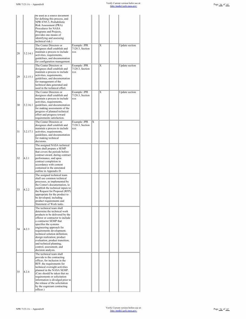
be used as a source document
for defining this process, and
NPR 8705.5, Probabilistic
Risk Assessment (PRA)
Procedures for NASA
Programs and Projects,
provides one means of
identifying and assessing
technical risk.)
28 3.2.14.1
The Center Directors or
designees shall establish and
maintain a process to include
activities, requirements,
guidelines, and documentation
for configuration management.
Example: JPR
7120.3, Section
xxx
X Update section
29 3.2.15.1
The Center Directors or
designees shall establish and
maintain a process to include
activities, requirements,
guidelines, and documentation
for management of the
technical data generated and
used in the technical effort.
Example: JPR
7120.3, Section
xxx
X Update section
30 3.2.16.1
The Center Directors or
designees shall establish and
maintain a process to include
activities, requirements,
guidelines, and documentation
for making assessments of the
progress of planned technical
effort and progress toward
requirements satisfaction.
Example: JPR
7120.3, Section
xxx
X Update section
31 3.2.17.1
The Center Directors or
designees shall establish and
maintain a process to include
activities, requirements,
guidelines, and documentation
for making technical
decisions.
Example: JPR
7120.3, Section
xxx
X
32 4.2.1
The assigned NASA technical
team shall prepare a SEMP
that covers the periods before
contract award, during contract
performance, and upon
contract completion in
accordance with content
contained in the annotated
outline in Appendix D.
33 4.2.2
The assigned technical team
shall use common technical
processes, as implemented by
the Center's documentation, to
establish the technical inputs to
the Request for Proposal (RFP)
appropriate for the product to
be developed, including
product requirements and
Statement of Work tasks.
34 4.2.3
The technical team shall
determine the technical work
products to be delivered by the
offeror or contractor to include
a contractor SEMP that
specifies the systems
engineering approach for
requirements development;
technical solution definition;
design realization; product
evaluation; product transition;
and technical planning,
control, assessment, and
decision analysis.
35 4.2.4
The technical team shall
provide to the contracting
officer, for inclusion in the
RFP, the requirements for
technical oversight activities
planned in the NASA SEMP.
(Care should be taken that no
requirements or solicitation
information is divulged prior to
the release of the solicitation
by the cognizant contracting
officer.)
NPR 7123.1A -- AppendixHVerify Current version before use at:
http://nodis3.gsfc.nasa.gov/Page 70 of 97
NPR 7123.1A -- AppendixHVerify Current version befor use at:
http://nodis3.gsfc.nasa.gov/Page 70 of 97
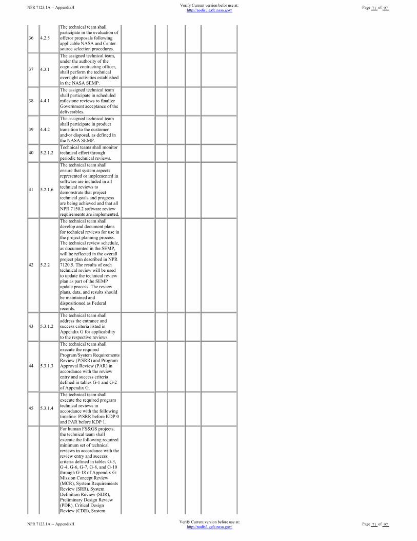
36 4.2.5
The technical team shall
participate in the evaluation of
offeror proposals following
applicable NASA and Center
source selection procedures.
37 4.3.1
The assigned technical team,
under the authority of the
cognizant contracting officer,
shall perform the technical
oversight activities established
in the NASA SEMP.
38 4.4.1
The assigned technical team
shall participate in scheduled
milestone reviews to finalize
Government acceptance of the
deliverables.
39 4.4.2
The assigned technical team
shall participate in product
transition to the customer
and/or disposal, as defined in
the NASA SEMP.
40 5.2.1.2
Technical teams shall monitor
technical effort through
periodic technical reviews.
41 5.2.1.6
The technical team shall
ensure that system aspects
represented or implemented in
software are included in all
technical reviews to
demonstrate that project
technical goals and progress
are being achieved and that all
NPR 7150.2 software review
requirements are implemented.
42 5.2.2
The technical team shall
develop and document plans
for technical reviews for use in
the project planning process.
The technical review schedule,
as documented in the SEMP,
will be reflected in the overall
project plan described in NPR
7120.5. The results of each
technical review will be used
to update the technical review
plan as part of the SEMP
update process. The review
plans, data, and results should
be maintained and
dispositioned as Federal
records.
43 5.3.1.2
The technical team shall
address the entrance and
success criteria listed in
Appendix G for applicability
to the respective reviews.
44 5.3.1.3
The technical team shall
execute the required
Program/System Requirements
Review (P/SRR) and Program
Approval Review (PAR) in
accordance with the review
entry and success criteria
defined in tables G-1 and G-2
of Appendix G.
45 5.3.1.4
The technical team shall
execute the required program
technical reviews in
accordance with the following
timeline: P/SRR before KDP 0
and PAR before KDP 1.
For human FS&GS projects,
the technical team shall
execute the following required
minimum set of technical
reviews in accordance with the
review entry and success
criteria defined in tables G-3,
G-4, G-6, G-7, G-8, and G-10
through G-18 of Appendix G:
Mission Concept Review
(MCR), System Requirements
Review (SRR), System
Definition Review (SDR),
Preliminary Design Review
(PDR), Critical Design
Review (CDR), System
NPR 7123.1A -- AppendixHVerify Current version before use at:
http://nodis3.gsfc.nasa.gov/Page 71 of 97
NPR 7123.1A -- AppendixHVerify Current version befor use at:
http://nodis3.gsfc.nasa.gov/Page 71 of 97
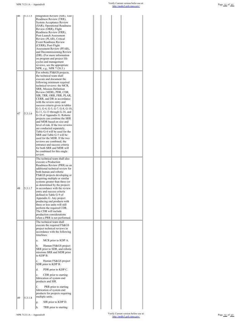
46 5.3.1.5 Integration Review (SIR), Test
Readiness Review (TRR),
System Acceptance Review
(SAR), Operational Readiness
Review (ORR), Flight
Readiness Review (FRR),
Post-Launch Assessment
Review (PLAR), Critical
Event Readiness Review
(CERR), Post-Flight
Assessment Review (PFAR),
and Decommissioning Review
(DR). (For more information
on program and project life
cycles and management
reviews, see the appropriate
NPR, e.g., NPR 7120.5.)
47 5.3.1.6
For robotic FS&GS projects,
the technical team shall
execute and document the
following minimum required
technical reviews: the MCR,
SRR, Mission Definition
Review (MDR), PDR, CDR,
SIR, TRR, ORR, FRR, PLAR,
CERR, and DR in accordance
with the review entry and
success criteria given in tables
G-3, G-4, G-5, G-7, G-8, G-10,
G-11, G-13 through G-16, and
G-18 of Appendix G. Robotic
projects can combine the SRR
and MDR based on size and
level of risk. If the two reviews
are conducted separately,
Table G-4 will be used for the
SRR and Table G-5 will be
used for the MDR. If the two
reviews are combined, the
entrance and success criteria
for both SRR and MDR will
be combined for this single
review.
48 5.3.1.7
The technical team shall also
execute a Production
Readiness Review (PRR) as an
additional technical review for
both human and robotic
FS&GS projects developing or
acquiring multiple or similar
systems greater than three (or
as determined by the project)
in accordance with the review
entry and success criteria
defined in Table G-9 of
Appendix G. Any project
producing end products with
three or less units will still
perform the required CDR.
The CDR will include
production considerations
when a PRR is not performed.
49 5.3.1.8
The technical team shall
execute the required FS&GS
project technical reviews in
accordance with the following
timelines:
a. MCR prior to KDP A.
b. Human FS&GS project
SRR prior to SDR, and robotic
missions SRR and MDR prior
to KDP B.
c. Human FS&GS project
SDR prior to KDP B.
d. PDR prior to KDP C.
e. CDR prior to starting
fabrication of system end
products and SIR.
f. PRR prior to starting
fabrication of system end
products for projects requiring
multiple units.
g. SIR prior to KDP D.
h. TRR prior to starting
NPR 7123.1A -- AppendixHVerify Current version before use at:
http://nodis3.gsfc.nasa.gov/Page 72 of 97
NPR 7123.1A -- AppendixHVerify Current version befor use at:
http://nodis3.gsfc.nasa.gov/Page 72 of 97
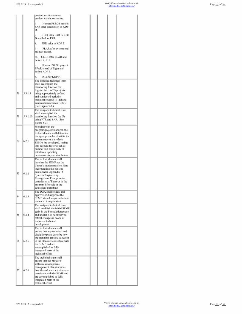
product verification and
product validation testing.
i. Human FS&GS project
SAR after completion of KDP
D.
j. ORR after SAR or KDP
D and before FRR.
k. FRR prior to KDP E.
l. PLAR after system end
product launch.
m. CERR after PLAR and
before KDP F.
n. Human FS&GS project
PFAR at end of flight and
before KDP F.
o. DR after KDP F.
50 5.3.1.9
The assigned technical team
shall accomplish the
monitoring function for
flight-related ATD projects
using appropriately defined
and conducted periodic
technical reviews (PTR) and
continuation reviews (CRs).
(See Figure 5-3.)
51 5.3.1.10
The assigned technical team
shall accomplish the
monitoring function for IPs
using PTR and SAR. (See
Figure 5-3.)
52 6.2.1
Working with the
program/project manager, the
technical team shall determine
the appropriate level within the
system structure at which
SEMPs are developed, taking
into account factors such as
number and complexity of
interfaces, operating
environments, and risk factors.
53 6.2.2
The technical team shall
baseline the SEMP per the
Center's Implementation Plan,
incorporating the content
contained in Appendix D,
Systems Engineering
Management Plan, prior to
completion of Phase A in the
program life cycle or the
equivalent milestone.
54 6.2.3
The DGA shall review and
approve or disapprove the
SEMP at each major milestone
review or its equivalent.
55 6.2.4
The assigned technical team
shall establish the initial SEMP
early in the Formulation phase
and update it as necessary to
reflect changes in scope or
improved technical
development.
56 6.2.5
The technical team shall
ensure that any technical and
discipline plans describe how
the technical activities covered
in the plans are consistent with
the SEMP and are
accomplished as fully
integrated parts of the
technical effort.
57 6.2.6
The technical team shall
ensure that the project's
software development/
management plan describes
how the software activities are
consistent with the SEMP and
are accomplished as fully
integrated parts of the
technical effort.
NPR 7123.1A -- AppendixHVerify Current version before use at:
http://nodis3.gsfc.nasa.gov/Page 73 of 97
NPR 7123.1A -- AppendixHVerify Current version befor use at:
http://nodis3.gsfc.nasa.gov/Page 73 of 97
3.3 Plan to close gaps
This section would include textual descriptions about how the gaps noted in the matrix will be closed.
4.0 Other
H-2 SE NPR Center Survey
SE NPR Center Survey
<Center Name>
Revision: <enter rev number>
<enter date>
NPR 7123.1A -- AppendixHVerify Current version before use at:
http://nodis3.gsfc.nasa.gov/Page 74 of 97
NPR 7123.1A -- AppendixHVerify Current version befor use at:
http://nodis3.gsfc.nasa.gov/Page 74 of 97
National Aeronautics and Space Administration
SE NPR Center Survey
<Center>
<Date>
Prepared by:
Name Date
Approved by:
Name
Date
Name
Date
Change Record
Rev. Date Originator Approvals Description
NPR 7123.1A -- AppendixHVerify Current version before use at:
http://nodis3.gsfc.nasa.gov/Page 75 of 97
NPR 7123.1A -- AppendixHVerify Current version befor use at:
http://nodis3.gsfc.nasa.gov/Page 75 of 97
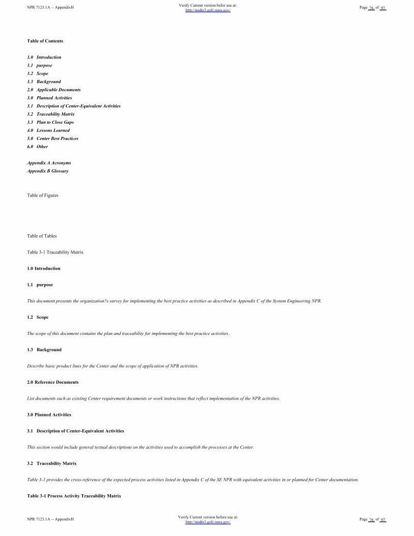
Table of Contents
1.0 Introduction
1.1 purpose
1.2 Scope
1.3 Background
2.0 Applicable Documents
3.0 Planned Activities
3.1 Description of Center-Equivalent Activities
3.2 Traceability Matrix
3.3 Plan to Close Gaps
4.0 Lessons Learned
5.0 Center Best Practices
6.0 Other
Appendix A Acronyms
Appendix B Glossary
Table of Figures
Table of Tables
Table 3-1 Traceability Matrix
1.0 Introduction
1.1 purpose
This document presents the organization?s survey for implementing the best practice activities as described in Appendix C of the System Engineering NPR.
1.2 Scope
The scope of this document contains the plan and traceability for implementing the best practice activities.
1.3 Background
Describe basic product lines for the Center and the scope of application of NPR activities.
2.0 Reference Documents
List documents such as existing Center requirement documents or work instructions that reflect implementation of the NPR activities.
3.0 Planned Activities
3.1 Description of Center-Equivalent Activities
This section would include general textual descriptions on the activities used to accomplish the processes at the Center.
3.2 Traceability Matrix
Table 3-1 provides the cross-reference of the expected process activities listed in Appendix C of the SE NPR with equivalent activities in or planned for Center documentation.
Table 3-1 Process Activity Traceability Matrix
NPR 7123.1A -- AppendixHVerify Current version before use at:
http://nodis3.gsfc.nasa.gov/Page 76 of 97
NPR 7123.1A -- AppendixHVerify Current version befor use at:
http://nodis3.gsfc.nasa.gov/Page 76 of 97
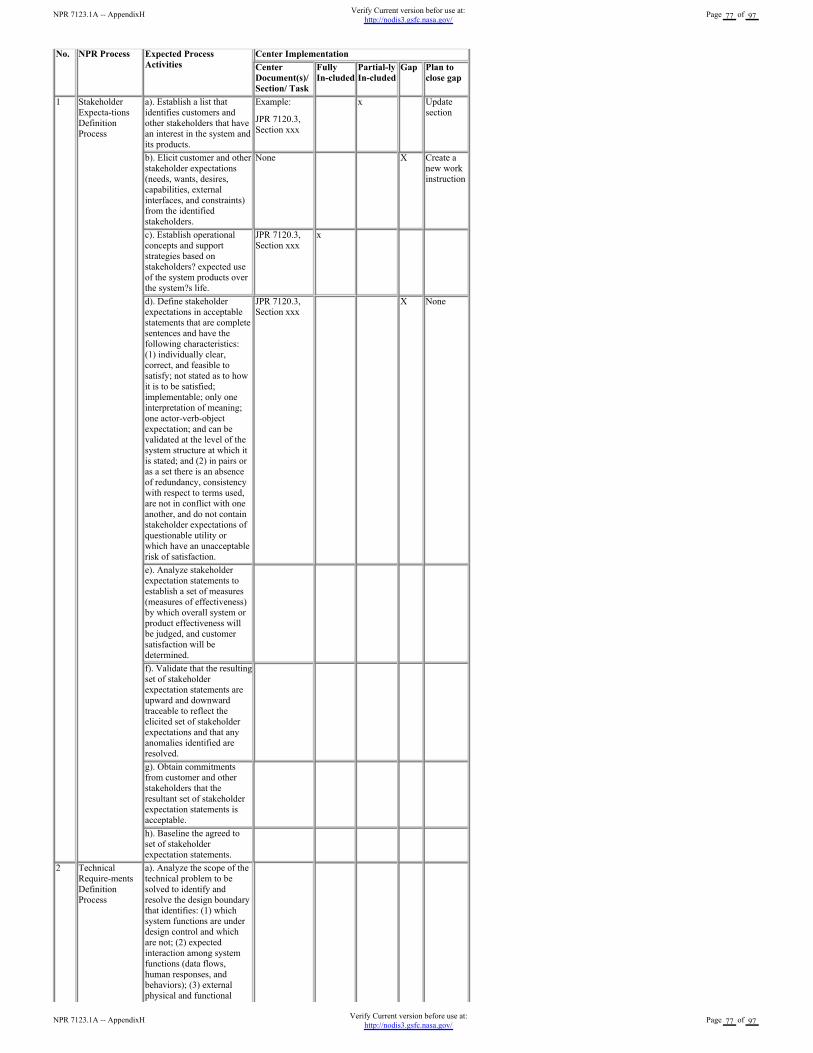
No. NPR Process Expected Process
Activities
Center Implementation
Center
Document(s)/
Section/ Task
Fully
In-cluded
Partial-ly
In-cluded
Gap Plan to
close gap
1 Stakeholder
Expecta-tions
Definition
Process
a). Establish a list that
identifies customers and
other stakeholders that have
an interest in the system and
its products.
Example:
JPR 7120.3,
Section xxx
x Update
section
b). Elicit customer and other
stakeholder expectations
(needs, wants, desires,
capabilities, external
interfaces, and constraints)
from the identified
stakeholders.
None X Create a
new work
instruction
c). Establish operational
concepts and support
strategies based on
stakeholders? expected use
of the system products over
the system?s life.
JPR 7120.3,
Section xxx
x
d). Define stakeholder
expectations in acceptable
statements that are complete
sentences and have the
following characteristics:
(1) individually clear,
correct, and feasible to
satisfy; not stated as to how
it is to be satisfied;
implementable; only one
interpretation of meaning;
one actor-verb-object
expectation; and can be
validated at the level of the
system structure at which it
is stated; and (2) in pairs or
as a set there is an absence
of redundancy, consistency
with respect to terms used,
are not in conflict with one
another, and do not contain
stakeholder expectations of
questionable utility or
which have an unacceptable
risk of satisfaction.
JPR 7120.3,
Section xxx
X None
e). Analyze stakeholder
expectation statements to
establish a set of measures
(measures of effectiveness)
by which overall system or
product effectiveness will
be judged, and customer
satisfaction will be
determined.
f). Validate that the resulting
set of stakeholder
expectation statements are
upward and downward
traceable to reflect the
elicited set of stakeholder
expectations and that any
anomalies identified are
resolved.
g). Obtain commitments
from customer and other
stakeholders that the
resultant set of stakeholder
expectation statements is
acceptable.
h). Baseline the agreed to
set of stakeholder
expectation statements.
2 Technical
Require-ments
Definition
Process
a). Analyze the scope of the
technical problem to be
solved to identify and
resolve the design boundary
that identifies: (1) which
system functions are under
design control and which
are not; (2) expected
interaction among system
functions (data flows,
human responses, and
behaviors); (3) external
physical and functional
NPR 7123.1A -- AppendixHVerify Current version before use at:
http://nodis3.gsfc.nasa.gov/Page 77 of 97
NPR 7123.1A -- AppendixHVerify Current version befor use at:
http://nodis3.gsfc.nasa.gov/Page 77 of 97
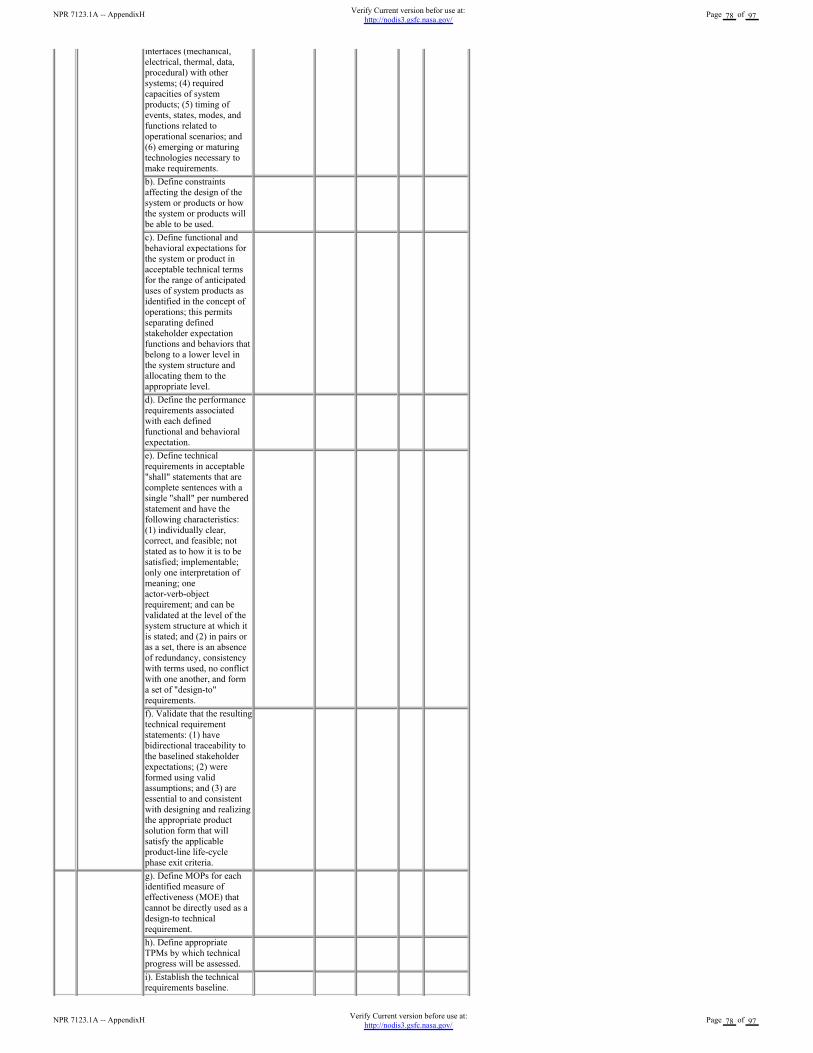
interfaces (mechanical,
electrical, thermal, data,
procedural) with other
systems; (4) required
capacities of system
products; (5) timing of
events, states, modes, and
functions related to
operational scenarios; and
(6) emerging or maturing
technologies necessary to
make requirements.
b). Define constraints
affecting the design of the
system or products or how
the system or products will
be able to be used.
c). Define functional and
behavioral expectations for
the system or product in
acceptable technical terms
for the range of anticipated
uses of system products as
identified in the concept of
operations; this permits
separating defined
stakeholder expectation
functions and behaviors that
belong to a lower level in
the system structure and
allocating them to the
appropriate level.
d). Define the performance
requirements associated
with each defined
functional and behavioral
expectation.
e). Define technical
requirements in acceptable
"shall" statements that are
complete sentences with a
single "shall" per numbered
statement and have the
following characteristics:
(1) individually clear,
correct, and feasible; not
stated as to how it is to be
satisfied; implementable;
only one interpretation of
meaning; one
actor-verb-object
requirement; and can be
validated at the level of the
system structure at which it
is stated; and (2) in pairs or
as a set, there is an absence
of redundancy, consistency
with terms used, no conflict
with one another, and form
a set of "design-to"
requirements.
f). Validate that the resulting
technical requirement
statements: (1) have
bidirectional traceability to
the baselined stakeholder
expectations; (2) were
formed using valid
assumptions; and (3) are
essential to and consistent
with designing and realizing
the appropriate product
solution form that will
satisfy the applicable
product-line life-cycle
phase exit criteria.
g). Define MOPs for each
identified measure of
effectiveness (MOE) that
cannot be directly used as a
design-to technical
requirement.
h). Define appropriate
TPMs by which technical
progress will be assessed.
i). Establish the technical
requirements baseline.
NPR 7123.1A -- AppendixHVerify Current version before use at:
http://nodis3.gsfc.nasa.gov/Page 78 of 97
NPR 7123.1A -- AppendixHVerify Current version befor use at:
http://nodis3.gsfc.nasa.gov/Page 78 of 97
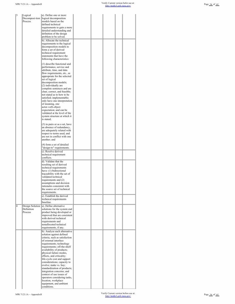
3 Logical
Decomposi-tion
Process
a). Define one or more
logical decomposition
models based on the
defined technical
requirements to gain a more
detailed understanding and
definition of the design
problem to be solved.
b). Allocate the technical
requirements to the logical
decomposition models to
form a set of derived
technical requirement
statements that have the
following characteristics:
(1) describe functional and
performance, service and
attribute, time, and data
flow requirements, etc., as
appropriate for the selected
set of logical
decomposition models;
(2) individually are
complete sentences and are
clear, correct, and feasible;
not stated as to how to be
satisfied; implementable;
only have one interpretation
of meaning, one
actor-verb-object
expectation; and can be
validated at the level of the
system structure at which it
is stated;
(3) in pairs or as a set, have
an absence of redundancy,
are adequately related with
respect to terms used, and
are not in conflict with one
another; and
(4) form a set of detailed
"design-to" requirements.
c). Resolve derived
technical requirement
conflicts.
d). Validate that the
resulting set of derived
technical requirements
have: (1) bidirectional
traceability with the set of
validated technical
requirements and (2)
assumptions and decision
rationales consistent with
the source set of technical
requirements.
e). Establish the derived
technical requirements
baseline.
4 Design Solution
Definition
Process
a). Define alternative
solutions for the system end
product being developed or
improved that are consistent
with derived technical
requirements and
nonallocated technical
requirements, if any.
b). Analyze each alternative
solution against defined
criteria, such as satisfaction
of external interface
requirements; technology
requirements; off-the-shelf
availability of products;
physical failure modes,
effects, and criticality;
life-cycle cost and support
considerations; capacity to
evolve; make vs. buy;
standardization of products;
integration concerns; and
context of use issues of
operators considering tasks,
location, workplace
equipment, and ambient
conditions.
NPR 7123.1A -- AppendixHVerify Current version before use at:
http://nodis3.gsfc.nasa.gov/Page 79 of 97
NPR 7123.1A -- AppendixHVerify Current version befor use at:
http://nodis3.gsfc.nasa.gov/Page 79 of 97
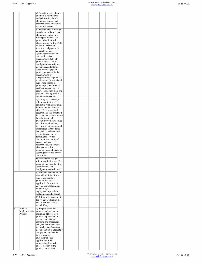
c). Select the best solution
alternative based on the
analysis results of each
alternative solution and
technical decision analysis
recommendations.
d). Generate the full design
description of the selected
alternative solution in a
form appropriate to the
product-line life-cycle
phase, location of the WBS
model in the system
structure, and phase exit
criteria to include: (1)
system specification and
external interface
specifications; (2) end
product specifications,
configuration description
documents, and interface
specifications; (3) end
product subsystem initial
specifications, if
subsystems are required; (4)
requirements for associated
supporting enabling
products; (5) end product
verification plan; (6) end
product validation plan; and
(7) applicable logistics and
operate-to procedures.
e). Verify that the design
solution definition: (1) is
realizable within constraints
imposed on the technical
effort; (2) has specified
requirements that are stated
in acceptable statements and
have bidirectional
traceability with the derived
technical requirements,
technical requirements, and
stakeholder expectations;
and (3) has decisions and
assumptions made in
forming the solution
consistent with its set of
derived technical
requirements, separately
allocated technical
requirements, and identified
system product and service
constraints.
f). Baseline the design
solution definition specified
requirements including the
specifications and
configuration descriptions.
g). Initiate development or
acquisition of the life-cycle
supporting enabling
products needed, as
applicable, for research,
development, fabrication,
integration, test,
deployment, operations,
sustainment, and disposal.
h). Initiate development of
the system products of the
next lower level WBS
model, if any.
5 Product
Implementa-tion
Process
a). Prepare to conduct
product implementation
including: (1) prepare a
product implementation
strategy and detailed
planning and procedures
and (2) determine whether
the product configuration
documentation is adequately
complete to conduct the
type of product
implementation as
applicable for the
product-line life-cycle
phase, location of the
product in the system
NPR 7123.1A -- AppendixHVerify Current version before use at:
http://nodis3.gsfc.nasa.gov/Page 80 of 97
NPR 7123.1A -- AppendixHVerify Current version befor use at:
http://nodis3.gsfc.nasa.gov/Page 80 of 97
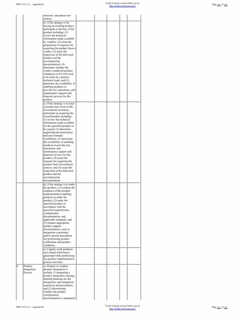
structure, and phase exit
criteria.
b). If the strategy is for
buying an existing product,
participate in the buy of the
product including: (1)
review the technical
information made available
by vendors; (2) assist the
preparation of requests for
acquiring the product from a
vendor; (3) assist the
inspection of the delivered
product and the
accompanying
documentation; (4)
determine whether the
vendor conducted product
validation or if it will need
to be done by a project
technical team; and (5)
determine the availability of
enabling products to
provide test, operations, and
maintenance support and
disposal services for the
product.
c). If the strategy is to reuse
a product that exists in the
Government inventory,
participate in acquiring the
reused product including:
(1) review the technical
information made available
for the specified product to
be reused; (2) determine
supporting documentation
and user manuals
availability; (3) determine
the availability of enabling
products to provide test,
operations, and
maintenance support and
disposal services for the
product; (4) assist the
requests for acquiring the
product from Government
sources; and (5) assist the
inspection of the delivered
product and the
accompanying
documentation.
d). If the strategy is to make
the product, (1) evaluate the
readiness of the product
implementation enabling
products to make the
product, (2) make the
specified product in
accordance with the
specified requirements,
configuration
documentation, and
applicable standards, and
(3) prepare appropriate
product support
documentation, such as
integration constraints
and/or special procedures
for performing product
verification and product
validation.
e). Capture work products
and related information
generated while performing
the product implementation
process activities.
6 Product
Integration
Process
a). Prepare to conduct
product integration to
include: (1) preparing a
product integration strategy,
detailed planning for the
integration, and integration
sequences and procedures;
and (2) determining
whether the product
configuration
documentation is adequately
complete to conduct the
NPR 7123.1A -- AppendixHVerify Current version before use at:
http://nodis3.gsfc.nasa.gov/Page 81 of 97
NPR 7123.1A -- AppendixHVerify Current version befor use at:
http://nodis3.gsfc.nasa.gov/Page 81 of 97
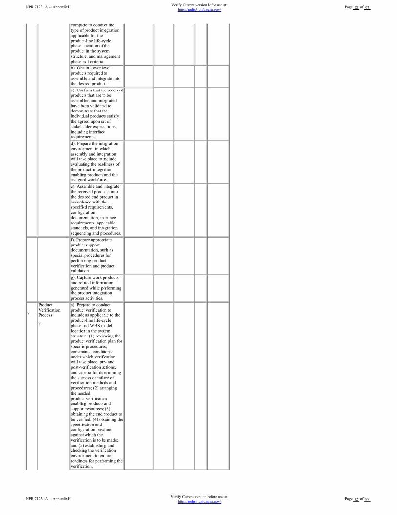
complete to conduct the
type of product integration
applicable for the
product-line life-cycle
phase, location of the
product in the system
structure, and management
phase exit criteria.
b). Obtain lower level
products required to
assemble and integrate into
the desired product.
c). Confirm that the received
products that are to be
assembled and integrated
have been validated to
demonstrate that the
individual products satisfy
the agreed upon set of
stakeholder expectations,
including interface
requirements.
d). Prepare the integration
environment in which
assembly and integration
will take place to include
evaluating the readiness of
the product-integration
enabling products and the
assigned workforce.
e). Assemble and integrate
the received products into
the desired end product in
accordance with the
specified requirements,
configuration
documentation, interface
requirements, applicable
standards, and integration
sequencing and procedures.
f). Prepare appropriate
product support
documentation, such as
special procedures for
performing product
verification and product
validation.
g). Capture work products
and related information
generated while performing
the product integration
process activities.
7
Product
Verification
Process
?
a). Prepare to conduct
product verification to
include as applicable to the
product-line life-cycle
phase and WBS model
location in the system
structure: (1) reviewing the
product verification plan for
specific procedures,
constraints, conditions
under which verification
will take place, pre- and
post-verification actions,
and criteria for determining
the success or failure of
verification methods and
procedures; (2) arranging
the needed
product-verification
enabling products and
support resources; (3)
obtaining the end product to
be verified; (4) obtaining the
specification and
configuration baseline
against which the
verification is to be made;
and (5) establishing and
checking the verification
environment to ensure
readiness for performing the
verification.
NPR 7123.1A -- AppendixHVerify Current version before use at:
http://nodis3.gsfc.nasa.gov/Page 82 of 97
NPR 7123.1A -- AppendixHVerify Current version befor use at:
http://nodis3.gsfc.nasa.gov/Page 82 of 97
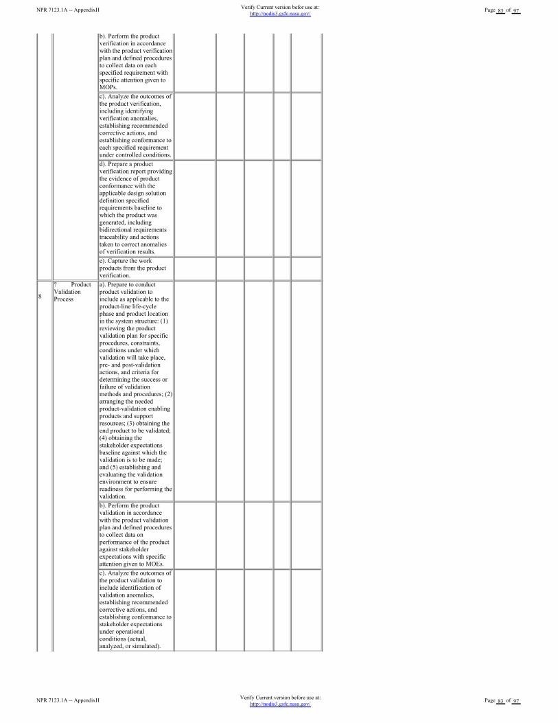
b). Perform the product
verification in accordance
with the product verification
plan and defined procedures
to collect data on each
specified requirement with
specific attention given to
MOPs.
c). Analyze the outcomes of
the product verification,
including identifying
verification anomalies,
establishing recommended
corrective actions, and
establishing conformance to
each specified requirement
under controlled conditions.
d). Prepare a product
verification report providing
the evidence of product
conformance with the
applicable design solution
definition specified
requirements baseline to
which the product was
generated, including
bidirectional requirements
traceability and actions
taken to correct anomalies
of verification results.
e). Capture the work
products from the product
verification.
8
? Product
Validation
Process
a). Prepare to conduct
product validation to
include as applicable to the
product-line life-cycle
phase and product location
in the system structure: (1)
reviewing the product
validation plan for specific
procedures, constraints,
conditions under which
validation will take place,
pre- and post-validation
actions, and criteria for
determining the success or
failure of validation
methods and procedures; (2)
arranging the needed
product-validation enabling
products and support
resources; (3) obtaining the
end product to be validated;
(4) obtaining the
stakeholder expectations
baseline against which the
validation is to be made;
and (5) establishing and
evaluating the validation
environment to ensure
readiness for performing the
validation.
b). Perform the product
validation in accordance
with the product validation
plan and defined procedures
to collect data on
performance of the product
against stakeholder
expectations with specific
attention given to MOEs.
c). Analyze the outcomes of
the product validation to
include identification of
validation anomalies,
establishing recommended
corrective actions, and
establishing conformance to
stakeholder expectations
under operational
conditions (actual,
analyzed, or simulated).
NPR 7123.1A -- AppendixHVerify Current version before use at:
http://nodis3.gsfc.nasa.gov/Page 83 of 97
NPR 7123.1A -- AppendixHVerify Current version befor use at:
http://nodis3.gsfc.nasa.gov/Page 83 of 97
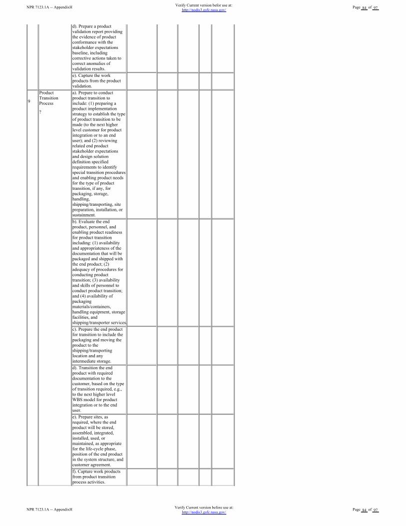
d). Prepare a product
validation report providing
the evidence of product
conformance with the
stakeholder expectations
baseline, including
corrective actions taken to
correct anomalies of
validation results.
e). Capture the work
products from the product
validation.
9
Product
Transition
Process
?
a). Prepare to conduct
product transition to
include: (1) preparing a
product implementation
strategy to establish the type
of product transition to be
made (to the next higher
level customer for product
integration or to an end
user); and (2) reviewing
related end product
stakeholder expectations
and design solution
definition specified
requirements to identify
special transition procedures
and enabling product needs
for the type of product
transition, if any, for
packaging, storage,
handling,
shipping/transporting, site
preparation, installation, or
sustainment.
b). Evaluate the end
product, personnel, and
enabling product readiness
for product transition
including: (1) availability
and appropriateness of the
documentation that will be
packaged and shipped with
the end product; (2)
adequacy of procedures for
conducting product
transition; (3) availability
and skills of personnel to
conduct product transition;
and (4) availability of
packaging
materials/containers,
handling equipment, storage
facilities, and
shipping/transporter services.
c). Prepare the end product
for transition to include the
packaging and moving the
product to the
shipping/transporting
location and any
intermediate storage.
d). Transition the end
product with required
documentation to the
customer, based on the type
of transition required, e.g.,
to the next higher level
WBS model for product
integration or to the end
user.
e). Prepare sites, as
required, where the end
product will be stored,
assembled, integrated,
installed, used, or
maintained, as appropriate
for the life-cycle phase,
position of the end product
in the system structure, and
customer agreement.
f). Capture work products
from product transition
process activities.
NPR 7123.1A -- AppendixHVerify Current version before use at:
http://nodis3.gsfc.nasa.gov/Page 84 of 97
NPR 7123.1A -- AppendixHVerify Current version befor use at:
http://nodis3.gsfc.nasa.gov/Page 84 of 97
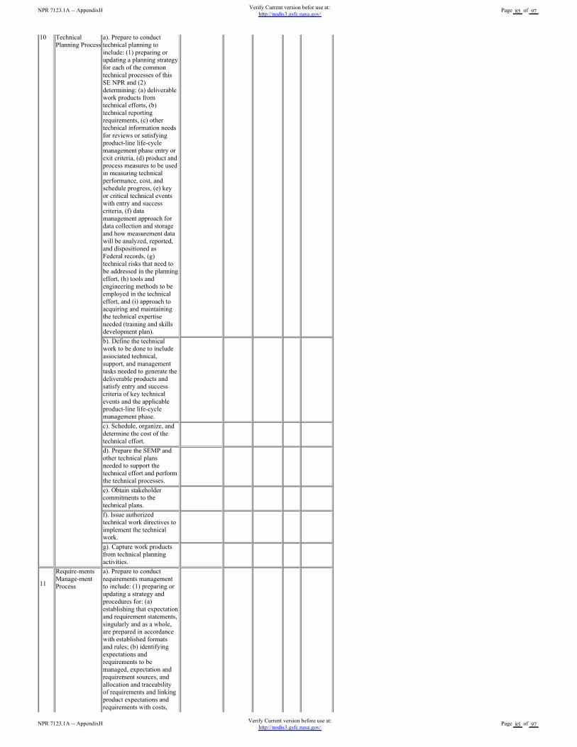
10 Technical
Planning Process
a). Prepare to conduct
technical planning to
include: (1) preparing or
updating a planning strategy
for each of the common
technical processes of this
SE NPR and (2)
determining: (a) deliverable
work products from
technical efforts, (b)
technical reporting
requirements, (c) other
technical information needs
for reviews or satisfying
product-line life-cycle
management phase entry or
exit criteria, (d) product and
process measures to be used
in measuring technical
performance, cost, and
schedule progress, (e) key
or critical technical events
with entry and success
criteria, (f) data
management approach for
data collection and storage
and how measurement data
will be analyzed, reported,
and dispositioned as
Federal records, (g)
technical risks that need to
be addressed in the planning
effort, (h) tools and
engineering methods to be
employed in the technical
effort, and (i) approach to
acquiring and maintaining
the technical expertise
needed (training and skills
development plan).
b). Define the technical
work to be done to include
associated technical,
support, and management
tasks needed to generate the
deliverable products and
satisfy entry and success
criteria of key technical
events and the applicable
product-line life-cycle
management phase.
c). Schedule, organize, and
determine the cost of the
technical effort.
d). Prepare the SEMP and
other technical plans
needed to support the
technical effort and perform
the technical processes.
e). Obtain stakeholder
commitments to the
technical plans.
f). Issue authorized
technical work directives to
implement the technical
work.
g). Capture work products
from technical planning
activities.
11
Require-ments
Manage-ment
Process
a). Prepare to conduct
requirements management
to include: (1) preparing or
updating a strategy and
procedures for: (a)
establishing that expectation
and requirement statements,
singularly and as a whole,
are prepared in accordance
with established formats
and rules; (b) identifying
expectations and
requirements to be
managed, expectation and
requirement sources, and
allocation and traceability
of requirements and linking
product expectations and
requirements with costs,
NPR 7123.1A -- AppendixHVerify Current version before use at:
http://nodis3.gsfc.nasa.gov/Page 85 of 97
NPR 7123.1A -- AppendixHVerify Current version befor use at:
http://nodis3.gsfc.nasa.gov/Page 85 of 97
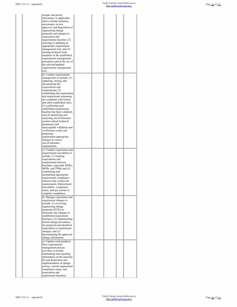
weight, and power
allocations, as applicable;
and (c) formal initiation,
assessment, review,
approval, and disposition of
engineering change
proposals and changes to
expectation and
requirements baseline; (2)
selecting or updating an
appropriate requirements
management tool; and (3)
training technical team
members in the established
requirements management
procedures and in the use of
the selected/updated
requirements management
tool.
b). Conduct requirements
management to include: (1)
capturing, storing, and
documenting the
expectations and
requirements; (2)
establishing that expectation
and requirement statements
are compliant with format
and other established rules;
(3) confirming each
established requirements
baseline has been validated;
and (4) identifying and
analyzing out-of-tolerance
system-critical technical
parameters and
unacceptable validation and
verification results and
proposing
requirement-appropriate
changes to correct
out-of-tolerance
requirements.
c). Conduct expectation and
requirements traceability to
include: (1) tracking
expectations and
requirements between
baselines, especially MOEs,
MOPs, and TPMs and (2)
establishing and
maintaining appropriate
requirements compliance
matrixes that contain the
requirements, bidirectional
traceability, compliance
status, and any actions to
complete compliance.
d). Manage expectation and
requirement changes to
include: (1) reviewing
engineering change
proposals (ECPs) to
determine any changes to
established requirement
baselines; (2) implementing
formal change procedures
for proposed and identified
expectation or requirement
changes; and (3)
disseminating the approved
change information.
e). Capture work products
from requirements
management process
activities to include
maintaining and reporting
information on the rationale
for and disposition and
implementation of change
actions, current requirement
compliance status, and
expectation and
requirement baselines.
NPR 7123.1A -- AppendixHVerify Current version before use at:
http://nodis3.gsfc.nasa.gov/Page 86 of 97
NPR 7123.1A -- AppendixHVerify Current version befor use at:
http://nodis3.gsfc.nasa.gov/Page 86 of 97
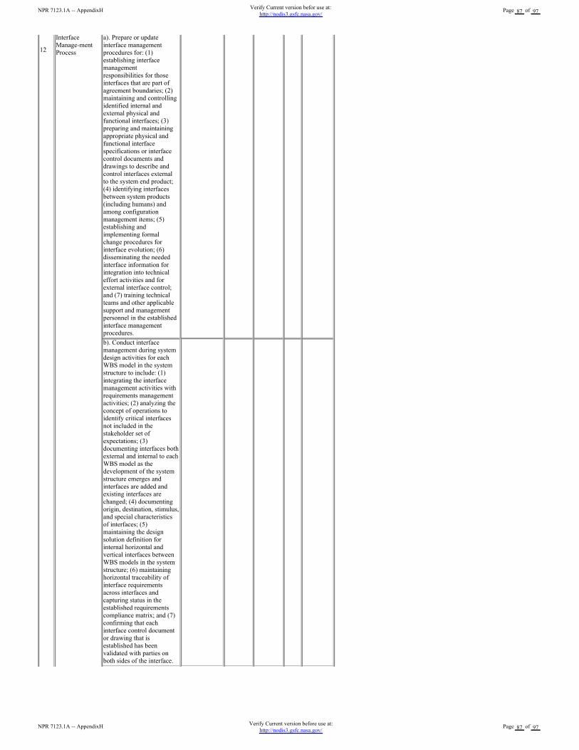
12
Interface
Manage-ment
Process
a). Prepare or update
interface management
procedures for: (1)
establishing interface
management
responsibilities for those
interfaces that are part of
agreement boundaries; (2)
maintaining and controlling
identified internal and
external physical and
functional interfaces; (3)
preparing and maintaining
appropriate physical and
functional interface
specifications or interface
control documents and
drawings to describe and
control interfaces external
to the system end product;
(4) identifying interfaces
between system products
(including humans) and
among configuration
management items; (5)
establishing and
implementing formal
change procedures for
interface evolution; (6)
disseminating the needed
interface information for
integration into technical
effort activities and for
external interface control;
and (7) training technical
teams and other applicable
support and management
personnel in the established
interface management
procedures.
b). Conduct interface
management during system
design activities for each
WBS model in the system
structure to include: (1)
integrating the interface
management activities with
requirements management
activities; (2) analyzing the
concept of operations to
identify critical interfaces
not included in the
stakeholder set of
expectations; (3)
documenting interfaces both
external and internal to each
WBS model as the
development of the system
structure emerges and
interfaces are added and
existing interfaces are
changed; (4) documenting
origin, destination, stimulus,
and special characteristics
of interfaces; (5)
maintaining the design
solution definition for
internal horizontal and
vertical interfaces between
WBS models in the system
structure; (6) maintaining
horizontal traceability of
interface requirements
across interfaces and
capturing status in the
established requirements
compliance matrix; and (7)
confirming that each
interface control document
or drawing that is
established has been
validated with parties on
both sides of the interface.
NPR 7123.1A -- AppendixHVerify Current version before use at:
http://nodis3.gsfc.nasa.gov/Page 87 of 97
NPR 7123.1A -- AppendixHVerify Current version befor use at:
http://nodis3.gsfc.nasa.gov/Page 87 of 97
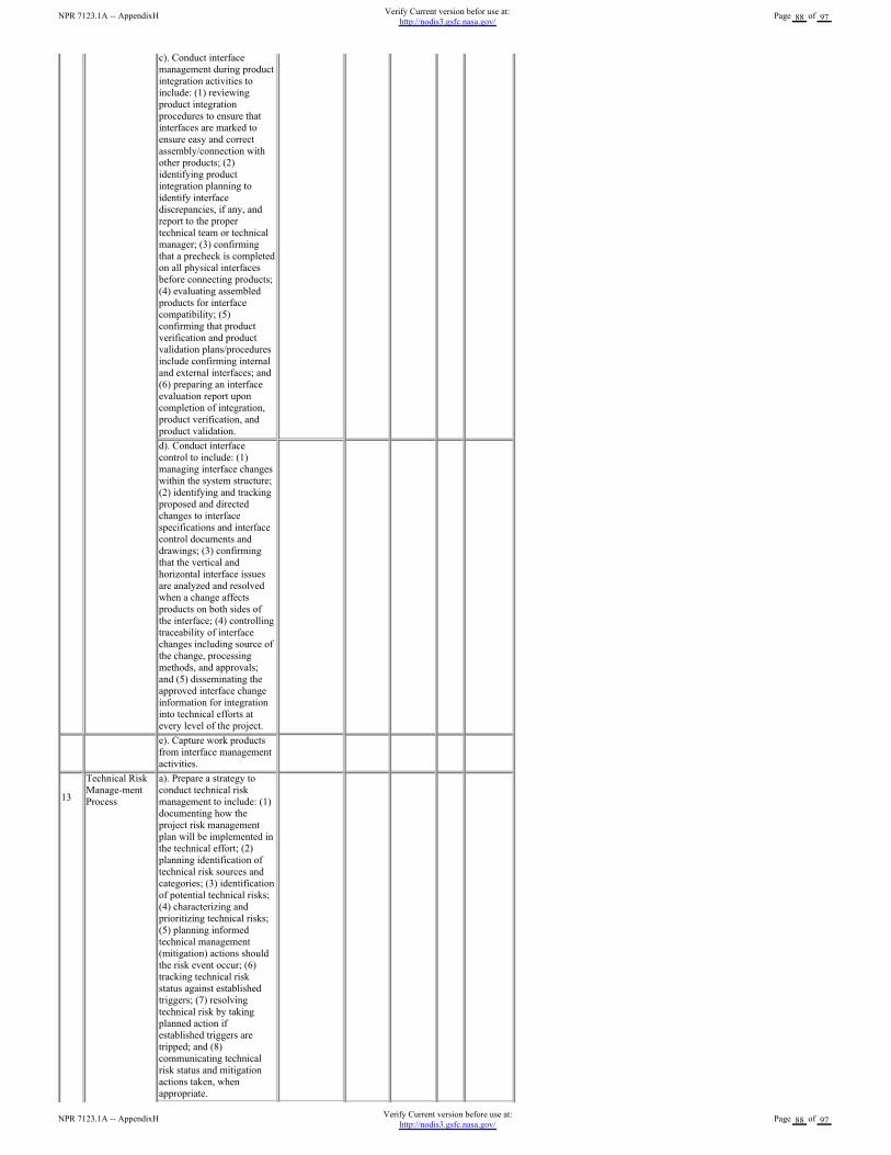
c). Conduct interface
management during product
integration activities to
include: (1) reviewing
product integration
procedures to ensure that
interfaces are marked to
ensure easy and correct
assembly/connection with
other products; (2)
identifying product
integration planning to
identify interface
discrepancies, if any, and
report to the proper
technical team or technical
manager; (3) confirming
that a precheck is completed
on all physical interfaces
before connecting products;
(4) evaluating assembled
products for interface
compatibility; (5)
confirming that product
verification and product
validation plans/procedures
include confirming internal
and external interfaces; and
(6) preparing an interface
evaluation report upon
completion of integration,
product verification, and
product validation.
d). Conduct interface
control to include: (1)
managing interface changes
within the system structure;
(2) identifying and tracking
proposed and directed
changes to interface
specifications and interface
control documents and
drawings; (3) confirming
that the vertical and
horizontal interface issues
are analyzed and resolved
when a change affects
products on both sides of
the interface; (4) controlling
traceability of interface
changes including source of
the change, processing
methods, and approvals;
and (5) disseminating the
approved interface change
information for integration
into technical efforts at
every level of the project.
e). Capture work products
from interface management
activities.
13
Technical Risk
Manage-ment
Process
a). Prepare a strategy to
conduct technical risk
management to include: (1)
documenting how the
project risk management
plan will be implemented in
the technical effort; (2)
planning identification of
technical risk sources and
categories; (3) identification
of potential technical risks;
(4) characterizing and
prioritizing technical risks;
(5) planning informed
technical management
(mitigation) actions should
the risk event occur; (6)
tracking technical risk
status against established
triggers; (7) resolving
technical risk by taking
planned action if
established triggers are
tripped; and (8)
communicating technical
risk status and mitigation
actions taken, when
appropriate.
NPR 7123.1A -- AppendixHVerify Current version before use at:
http://nodis3.gsfc.nasa.gov/Page 88 of 97
NPR 7123.1A -- AppendixHVerify Current version befor use at:
http://nodis3.gsfc.nasa.gov/Page 88 of 97
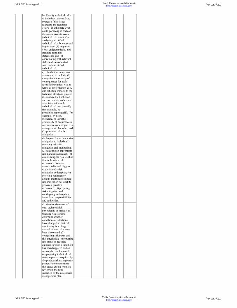
b). Identify technical risks
to include: (1) identifying
sources of risk issues
related to the technical
effort; (2) anticipate what
could go wrong in each of
the source areas to create
technical risk issues; (3)
analyzing identified
technical risks for cause and
importance; (4) preparing
clear, understandable, and
standard form risk
statements; and (5)
coordinating with relevant
stakeholders associated
with each identified
technical risk.
c). Conduct technical risk
assessment to include: (1)
categorize the severity of
consequences for each
identified technical risk in
terms of performance, cost,
and schedule impacts to the
technical effort and project;
(2) analyze the likelihood
and uncertainties of events
associated with each
technical risk and quantify
(for example, by
probabilities) or qualify (for
example, by high,
moderate, or low) the
probability of occurrence in
accordance with project risk
management plan rules; and
(3) prioritize risks for
mitigation.
d). Prepare for technical risk
mitigation to include: (1)
selecting risks for
mitigation and monitoring;
(2) selecting an appropriate
risk-handling approach; (3)
establishing the risk level or
threshold when risk
occurrence becomes
unacceptable and triggers
execution of a risk
mitigation action plan; (4)
selecting contingency
actions and triggers should
risk mitigation not work to
prevent a problem
occurrence; (5) preparing
risk mitigation and
contingency action plans
identifying responsibilities
and authorities.
e). Monitor the status of
each technical risk
periodically to include: (1)
tracking risk status to
determine whether
conditions or situations
have changed so that risk
monitoring is no longer
needed or new risks have
been discovered; (2)
comparing risk status and
risk thresholds; (3) reporting
risk status to decision
authorities when a threshold
has been triggered and an
action plan implemented;
(4) preparing technical risk
status reports as required by
the project risk management
plan; (5) communicating
risk status during technical
reviews in the form
specified by the project risk
management plan.
NPR 7123.1A -- AppendixHVerify Current version before use at:
http://nodis3.gsfc.nasa.gov/Page 89 of 97
NPR 7123.1A -- AppendixHVerify Current version befor use at:
http://nodis3.gsfc.nasa.gov/Page 89 of 97
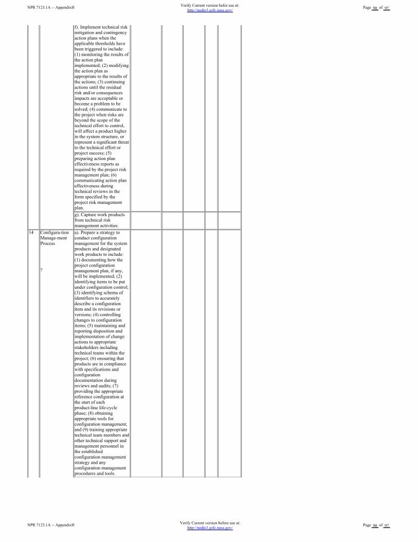
f). Implement technical risk
mitigation and contingency
action plans when the
applicable thresholds have
been triggered to include:
(1) monitoring the results of
the action plan
implemented; (2) modifying
the action plan as
appropriate to the results of
the actions; (3) continuing
actions until the residual
risk and/or consequences
impacts are acceptable or
become a problem to be
solved; (4) communicate to
the project when risks are
beyond the scope of the
technical effort to control,
will affect a product higher
in the system structure, or
represent a significant threat
to the technical effort or
project success; (5)
preparing action plan
effectiveness reports as
required by the project risk
management plan; (6)
communicating action plan
effectiveness during
technical reviews in the
form specified by the
project risk management
plan.
g). Capture work products
from technical risk
management activities.
14 Configura-tion
Manage-ment
Process
?
a). Prepare a strategy to
conduct configuration
management for the system
products and designated
work products to include:
(1) documenting how the
project configuration
management plan, if any,
will be implemented; (2)
identifying items to be put
under configuration control;
(3) identifying schema of
identifiers to accurately
describe a configuration
item and its revisions or
versions; (4) controlling
changes to configuration
items; (5) maintaining and
reporting disposition and
implementation of change
actions to appropriate
stakeholders including
technical teams within the
project; (6) enssuring that
products are in compliance
with specifications and
configuration
documentation during
reviews and audits; (7)
providing the appropriate
reference configuration at
the start of each
product-line life-cycle
phase; (8) obtaining
appropriate tools for
configuration management;
and (9) training appropriate
technical team members and
other technical support and
management personnel in
the established
configuration management
strategy and any
configuration management
procedures and tools.
NPR 7123.1A -- AppendixHVerify Current version before use at:
http://nodis3.gsfc.nasa.gov/Page 90 of 97
NPR 7123.1A -- AppendixHVerify Current version befor use at:
http://nodis3.gsfc.nasa.gov/Page 90 of 97

b). Identify baselines to be
under configuration control
to include: (1) listing of the
configuration items to
control; (2) providing each
configuration item with a
unique identifier; (3)
identifying acceptance
requirements for each
baseline identified for
control; (4) identifying the
owner of each configuration
item; and (5) establishing a
baseline configuration for
each configuration item.
c). Manage configuration
change control to include:
(1) establishing change
criteria, procedures, and
responsibilities; (2)
receiving, recording, and
evaluating change requests;
(3) tracking change
requests to closure; (4)
obtaining appropriate
approvals before
implementing a change; (5)
incorporating approved
changes in appropriate
configuration items; (6)
releasing changed
configuration items for use;
and (7) monitoring
implementation to
determine whether changes
resulted in unintended
effects (e.g., have
compromised safety or
security of baseline product).
d). Maintain the status of
configuration
documentation to include:
(1) maintaining
configuration item
description records and
records that verify readiness
of configuration items for
testing, delivery, or other
related technical efforts; (2)
maintaining change
requests, disposition action
taken, and history of
change status; (3)
maintaining differences
between successive
baselines; and (4)
controlling access to and
release of configuration
baselines.
e). Conduct configuration
audits to include: (1)
auditing baselines under
control to confirm that the
actual work product
configuration matches the
documented configuration,
the configuration is in
conformance with product
requirements, and records
of all change actions are
complete and up to date; (2)
identifying risks to the
technical effort based on
incorrect documentation,
implementation, or tracking
of changes; (3) assessing
the integrity of the
baselines; (4) confirming
the completeness and
correctness of the content of
configuration items with
applicable requirements; (5)
confirming compliance of
configuration items with
applicable configuration
management standards and
procedures; and (6) tracking
action items to correct
anomalies from audit to
NPR 7123.1A -- AppendixHVerify Current version before use at:
http://nodis3.gsfc.nasa.gov/Page 91 of 97
NPR 7123.1A -- AppendixHVerify Current version befor use at:
http://nodis3.gsfc.nasa.gov/Page 91 of 97
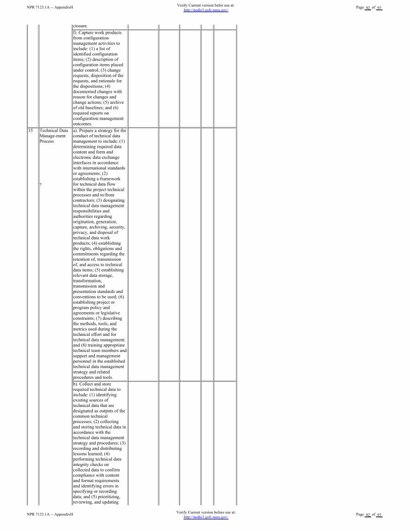
closure.
f). Capture work products
from configuration
management activities to
include: (1) a list of
identified configuration
items; (2) description of
configuration items placed
under control; (3) change
requests, disposition of the
requests, and rationale for
the dispositions; (4)
documented changes with
reason for changes and
change actions; (5) archive
of old baselines; and (6)
required reports on
configuration management
outcomes.
15 Technical Data
Manage-ment
Process
?
a). Prepare a strategy for the
conduct of technical data
management to include: (1)
determining required data
content and form and
electronic data exchange
interfaces in accordance
with international standards
or agreements; (2)
establishing a framework
for technical data flow
within the project technical
processes and to/from
contractors; (3) designating
technical data management
responsibilities and
authorities regarding
origination, generation,
capture, archiving, security,
privacy, and disposal of
technical data work
products; (4) establishing
the rights, obligations and
commitments regarding the
retention of, transmission
of, and access to technical
data items; (5) establishing
relevant data storage,
transformation,
transmission and
presentation standards and
conventions to be used; (6)
establishing project or
program policy and
agreements or legislative
constraints; (7) describing
the methods, tools, and
metrics used during the
technical effort and for
technical data management;
and (8) training appropriate
technical team members and
support and management
personnel in the established
technical data management
strategy and related
procedures and tools.
b). Collect and store
required technical data to
include: (1) identifying
existing sources of
technical data that are
designated as outputs of the
common technical
processes; (2) collecting
and storing technical data in
accordance with the
technical data management
strategy and procedures; (3)
recording and distributing
lessons learned; (4)
performing technical data
integrity checks on
collected data to confirm
compliance with content
and format requirements
and identifying errors in
specifying or recording
data; and (5) prioritizing,
reviewing, and updating
NPR 7123.1A -- AppendixHVerify Current version before use at:
http://nodis3.gsfc.nasa.gov/Page 92 of 97
NPR 7123.1A -- AppendixHVerify Current version befor use at:
http://nodis3.gsfc.nasa.gov/Page 92 of 97
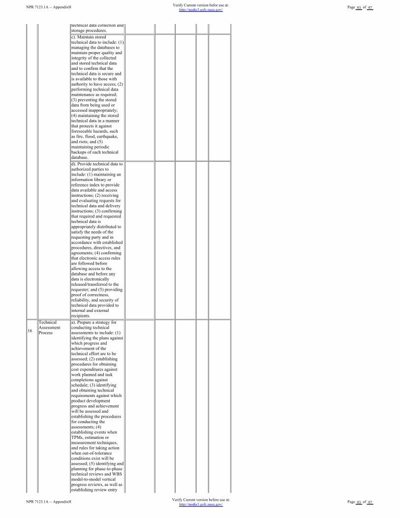
technical data collection and
storage procedures.
c). Maintain stored
technical data to include: (1)
managing the databases to
maintain proper quality and
integrity of the collected
and stored technical data
and to confirm that the
technical data is secure and
is available to those with
authority to have access; (2)
performing technical data
maintenance as required;
(3) preventing the stored
data from being used or
accessed inappropriately;
(4) maintaining the stored
technical data in a manner
that protects it against
foreseeable hazards, such
as fire, flood, earthquake,
and riots; and (5)
maintaining periodic
backups of each technical
database.
d). Provide technical data to
authorized parties to
include: (1) maintaining an
information library or
reference index to provide
data available and access
instructions; (2) receiving
and evaluating requests for
technical data and delivery
instructions; (3) confirming
that required and requested
technical data is
appropriately distributed to
satisfy the needs of the
requesting party and in
accordance with established
procedures, directives, and
agreements; (4) confirming
that electronic access rules
are followed before
allowing access to the
database and before any
data is electronically
released/transferred to the
requester; and (5) providing
proof of correctness,
reliability, and security of
technical data provided to
internal and external
recipients.
16
Technical
Assessment
Process
a). Prepare a strategy for
conducting technical
assessments to include: (1)
identifying the plans against
which progress and
achievement of the
technical effort are to be
assessed; (2) establishing
procedures for obtaining
cost expenditures against
work planned and task
completions against
schedule; (3) identifying
and obtaining technical
requirements against which
product development
progress and achievement
will be assessed and
establishing the procedures
for conducting the
assessments; (4)
establishing events when
TPMs, estimation or
measurement techniques,
and rules for taking action
when out-of-tolerance
conditions exist will be
assessed; (5) identifying and
planning for phase-to-phase
technical reviews and WBS
model-to-model vertical
progress reviews, as well as
establishing review entry
NPR 7123.1A -- AppendixHVerify Current version before use at:
http://nodis3.gsfc.nasa.gov/Page 93 of 97
NPR 7123.1A -- AppendixHVerify Current version befor use at:
http://nodis3.gsfc.nasa.gov/Page 93 of 97
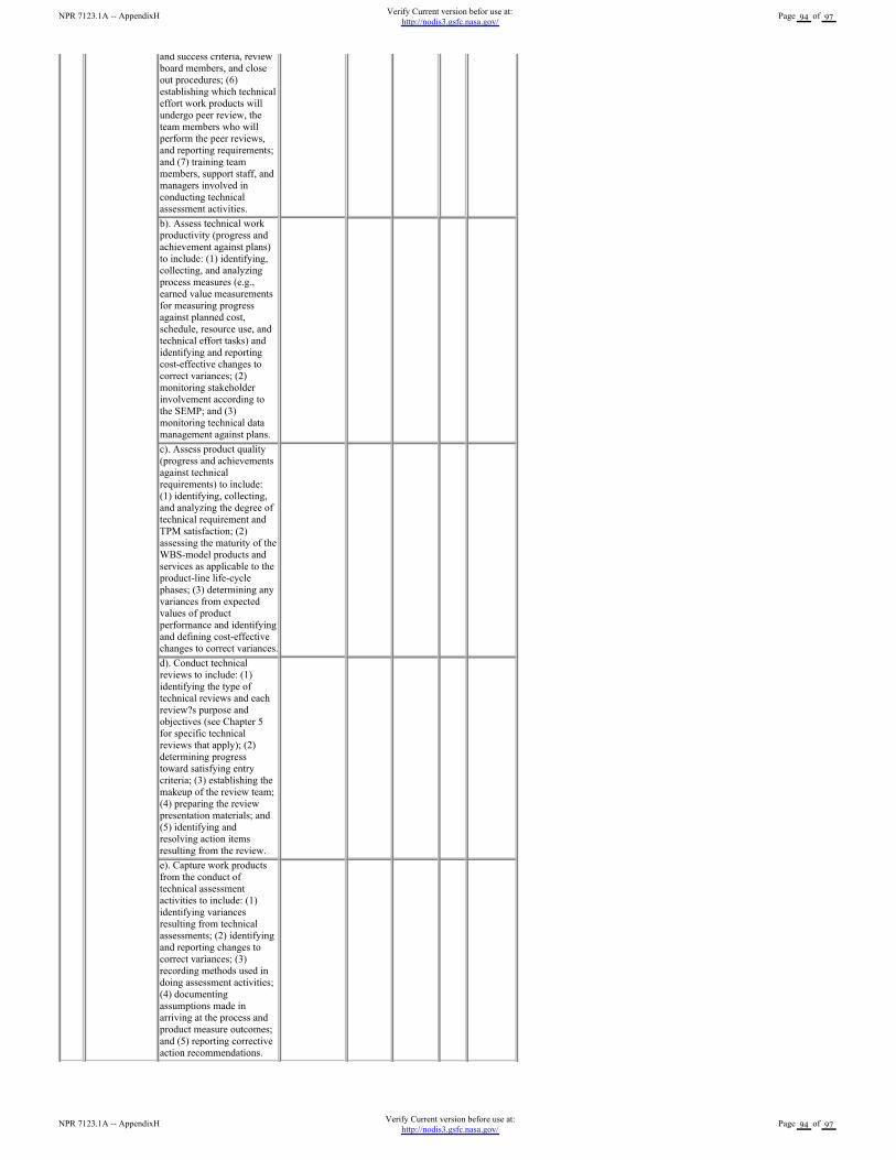
and success criteria, review
board members, and close
out procedures; (6)
establishing which technical
effort work products will
undergo peer review, the
team members who will
perform the peer reviews,
and reporting requirements;
and (7) training team
members, support staff, and
managers involved in
conducting technical
assessment activities.
b). Assess technical work
productivity (progress and
achievement against plans)
to include: (1) identifying,
collecting, and analyzing
process measures (e.g.,
earned value measurements
for measuring progress
against planned cost,
schedule, resource use, and
technical effort tasks) and
identifying and reporting
cost-effective changes to
correct variances; (2)
monitoring stakeholder
involvement according to
the SEMP; and (3)
monitoring technical data
management against plans.
c). Assess product quality
(progress and achievements
against technical
requirements) to include:
(1) identifying, collecting,
and analyzing the degree of
technical requirement and
TPM satisfaction; (2)
assessing the maturity of the
WBS-model products and
services as applicable to the
product-line life-cycle
phases; (3) determining any
variances from expected
values of product
performance and identifying
and defining cost-effective
changes to correct variances.
d). Conduct technical
reviews to include: (1)
identifying the type of
technical reviews and each
review?s purpose and
objectives (see Chapter 5
for specific technical
reviews that apply); (2)
determining progress
toward satisfying entry
criteria; (3) establishing the
makeup of the review team;
(4) preparing the review
presentation materials; and
(5) identifying and
resolving action items
resulting from the review.
e). Capture work products
from the conduct of
technical assessment
activities to include: (1)
identifying variances
resulting from technical
assessments; (2) identifying
and reporting changes to
correct variances; (3)
recording methods used in
doing assessment activities;
(4) documenting
assumptions made in
arriving at the process and
product measure outcomes;
and (5) reporting corrective
action recommendations.
NPR 7123.1A -- AppendixHVerify Current version before use at:
http://nodis3.gsfc.nasa.gov/Page 94 of 97
NPR 7123.1A -- AppendixHVerify Current version befor use at:
http://nodis3.gsfc.nasa.gov/Page 94 of 97
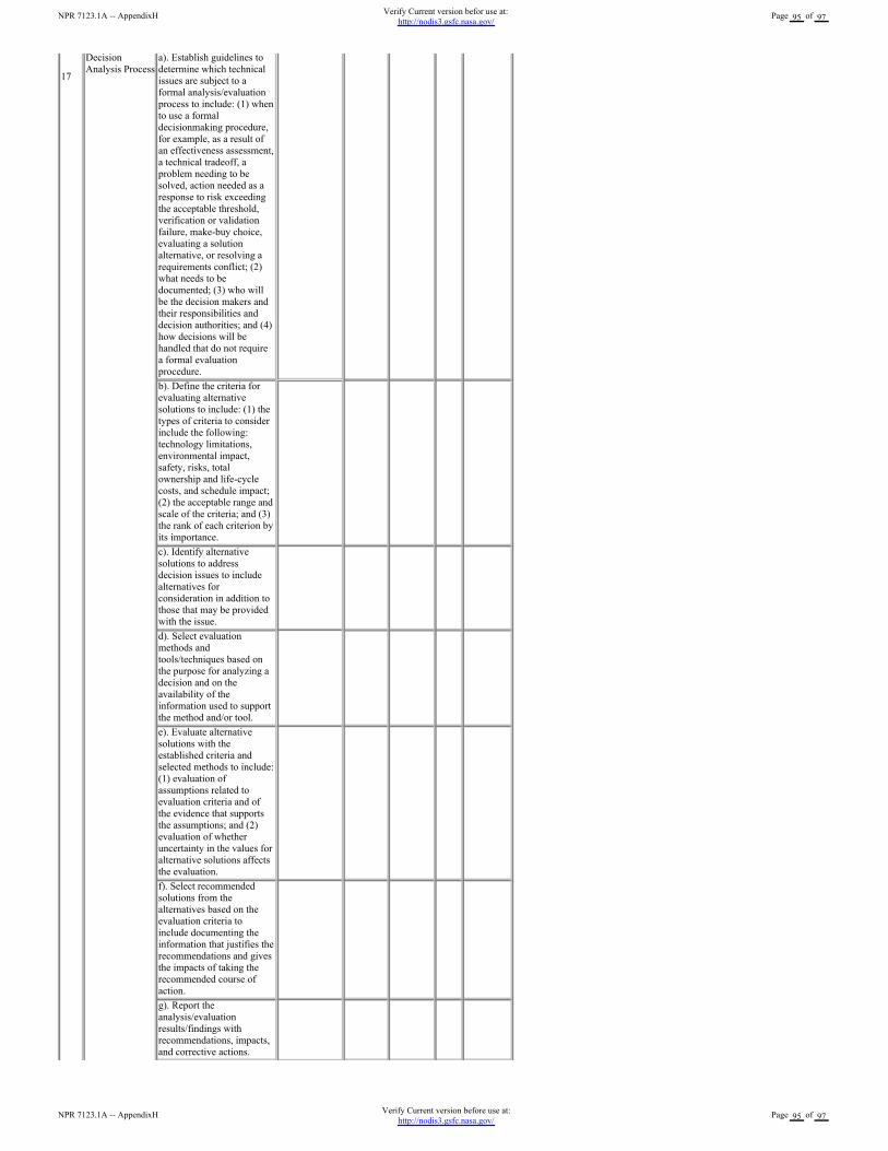
17
Decision
Analysis Process
a). Establish guidelines to
determine which technical
issues are subject to a
formal analysis/evaluation
process to include: (1) when
to use a formal
decisionmaking procedure,
for example, as a result of
an effectiveness assessment,
a technical tradeoff, a
problem needing to be
solved, action needed as a
response to risk exceeding
the acceptable threshold,
verification or validation
failure, make-buy choice,
evaluating a solution
alternative, or resolving a
requirements conflict; (2)
what needs to be
documented; (3) who will
be the decision makers and
their responsibilities and
decision authorities; and (4)
how decisions will be
handled that do not require
a formal evaluation
procedure.
b). Define the criteria for
evaluating alternative
solutions to include: (1) the
types of criteria to consider
include the following:
technology limitations,
environmental impact,
safety, risks, total
ownership and life-cycle
costs, and schedule impact;
(2) the acceptable range and
scale of the criteria; and (3)
the rank of each criterion by
its importance.
c). Identify alternative
solutions to address
decision issues to include
alternatives for
consideration in addition to
those that may be provided
with the issue.
d). Select evaluation
methods and
tools/techniques based on
the purpose for analyzing a
decision and on the
availability of the
information used to support
the method and/or tool.
e). Evaluate alternative
solutions with the
established criteria and
selected methods to include:
(1) evaluation of
assumptions related to
evaluation criteria and of
the evidence that supports
the assumptions; and (2)
evaluation of whether
uncertainty in the values for
alternative solutions affects
the evaluation.
f). Select recommended
solutions from the
alternatives based on the
evaluation criteria to
include documenting the
information that justifies the
recommendations and gives
the impacts of taking the
recommended course of
action.
g). Report the
analysis/evaluation
results/findings with
recommendations, impacts,
and corrective actions.
NPR 7123.1A -- AppendixHVerify Current version before use at:
http://nodis3.gsfc.nasa.gov/Page 95 of 97
NPR 7123.1A -- AppendixHVerify Current version befor use at:
http://nodis3.gsfc.nasa.gov/Page 95 of 97
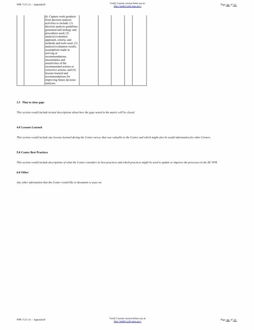
h). Capture work products
from decision analysis
activities to include: (1)
decision analysis guidelines
generated and strategy and
procedures used; (2)
analysis/evaluation
approach, criteria, and
methods and tools used; (3)
analysis/evaluation results,
assumptions made in
arriving at
recommendations,
uncertainties and
sensitivities of the
recommended actions or
corrective actions; and (4)
lessons learned and
recommendations for
improving future decision
analyses.
3.3 Plan to close gaps
This section would include textual descriptions about how the gaps noted in the matrix will be closed.
4.0 Lessons Learned
This section would include any lessons learned during the Center survey that was valuable to the Center and which might also be useful information for other Centers.
5.0 Center Best Practices
This section would include descriptions of what the Center considers its best practices and which practices might be used to update or improve the processes in the SE NPR.
6.0 Other
Any other information that the Center would like to document or pass on.
NPR 7123.1A -- AppendixHVerify Current version before use at:
http://nodis3.gsfc.nasa.gov/Page 96 of 97
NPR 7123.1A -- AppendixHVerify Current version befor use at:
http://nodis3.gsfc.nasa.gov/Page 96 of 97
Appendix I. Additional Reading
The following documents were used as reference materials in the development of this SE NPR. The documents are offered as informational sources and are not evoked in this SE NPR,though they may be referenced.
1. MIL-STD-499B (draft), Systems Engineering.
2. ISO/IEC 15288, System Life Cycle Processes.
ISO/IEC 15288 defines international system life processes plus for any domain (e.g., transportation, medical, commercial).
3. ANSI/EIA 632, Processes for Engineering a System.
EIA 632 is a commercial document that evolved from the never released, but fully developed, 1994 Mil-Std 499B Systems Engineering. It was intended to provide a framework fordeveloping and supporting universal SE discipline for both defense and commercial environments. EIA 632 was intended to be a top-tier standard further defined to lower level standardsthat define specific practices.
IEEE 1220 is a second-tier standard that implements EIA 632 by defining one way to practice systems engineering.
4. CMMI model.
The Capability Maturity Model® (CMM) IntegrationSM (CMMI) in its present form is a collection of best practices for the "development and maintenance" of both "products and services."The model was developed by integrating practices from four different CMMs, the "source models" the CMM for software, for systems engineering, for integrated product development(IPD), and for acquisition. Organizations can use the model to improve their ability to develop (or maintain) products (and services) on time, within budget, and with desired quality. CMMIalso provides these organizations the framework for enlarging the focus of process improvement to other areas that also affect product development, i.e., the discipline of systemsengineering. During the past decade, new and effective concepts for organizing developmental work have surfaced and been adopted, such as concurrent engineering or the use ofintegrated teams. Organizations using (or wishing to adopt these ideas) can also find support in the CMMI by using the model with integrated product and process development (IPPD)additions.
5. Defense Acquisition University Systems Engineering Fundamentals. Ft. Belvoir, Virginia: Defense Acquisition University Press, December 2000.
6. International Council on Systems Engineering Systems Engineering Guide.
7. ISO/IEC TR 19760, Systems Engineering A Guide for the Application of ISO/IEC 15288 (System Life Cycle Processes).
8. AS9100: Quality Management Systems Aerospace Requirements. G-14 Americas Aerospace Quality Group.
NPR 7123.1A -- AppendixIVerify Current version before use at:
http://nodis3.gsfc.nasa.gov/Page 97 of 97
NPR 7123.1A -- AppendixIVerify Current version befor use at:
http://nodis3.gsfc.nasa.gov/Page 97 of 97