Embed Size (px)
Citation preview

NASA METROLOGY INFORMATION SYSTEM - A NEMS SUBSYSTEM
Earl S. German, Jr_ and Frederick A. KernLangley Research Center
and
Rick Yow and Ellen Peterson
Planning Research Corporation
ABSTRACT
The NASA Metrology Information Systems (NMIS) is being developed as a
standardized tool in managing the NASA field Centers' instrument calibration
programs. This system, as defined by the NASA Metrology and Calibration
Workshop, will function as a subsystem of the newly developed NASA Equipment
Management System (NEMS). The Metrology Information System is designed to
utilize and update applicable NEMS data fields for controlled property and tofunction as a stand alone system for noncontrolled property. The NMIS pro-
vides automatic instrument calibration recall control, instrument historical
performance data storage and analysis, calibration and repair labor and partscost data, and instrument user and location data. Nineteen standardized
reports have been developed to analyze calibration system operations.
INTRODUCTION
The National Aeronautics and Space Administration has conducted an annual
workshop on metrology and calibration since 1977. The objectives of these
workshops were to ensure effective support for NASA's technical programs, to
identify areas where greater efficiency and economy could be achieved, and to
provide a unification of field Center objectives and responsibilities. The
workshops, under the sponsorship of NASA Headquarters' Office of Chief
Engineer, included representatives from Headquarters, each field Center,
support service contractors, and invited guests from other agencies such asthe National Bureau of Standards and the Department of Defense. For the past
2 years the workshop has been held in conjunction with the Department of
Energy's Standards Laboratories Manager's Conference.
The activities of these workshops have resulted in: (i) A unification
of responsibilities and objectives through the development of an agency-wide
management instruction, NMI 5330.9; (2) the development of a document describ-
ing the calibration capabilities of each Center; (3) an increase in the levelof communications between Center metrologists concerning management techniques,
calibration techniques, hardware, automatic calibration systems, software, and
procedures; (4) NASA-wide labels for calibration, limited calibration andstandards identification; and (5) the utilization and sharing of calibration
resources between government agencies. However, the individual Center's
89
https://ntrs.nasa.gov/search.jsp?R=19840025208 2018-06-21T05:41:20+00:00Z
metrology programs still had significant differences--particularly in the
procedures used to track instrument calibration histories, manpower usage,
and calibration laboratory performance. For example, Center metrologyprograms ranged from the simple instrument calibration with minimal documen-
tation and no instrument recall program to a system containing several thousand
instruments in recall and a sophisticated instrument and calibration laboratoryperformance documentation system.
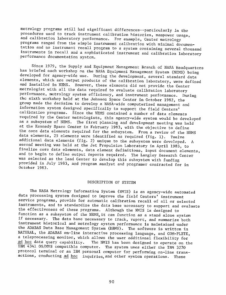
Since 1979, the Supply and Equipment Management Branch of NASA Headquarters
has briefed each workshop on the NASA Equipment Management System (NEMS) beingdeveloped for agency-wide use. During the development, several standard data
elements, which are output products of the calibration laboratory, were defined
and installed in NEMS. However, these elements did not provide the Center
metrologist with all the data required to evaluate calibration laboratory
performance, metrology system efficiency, and instrument performance. During
the sixth workshop held at the Johnson Space Center in October 1982, the
group made the decision to develop a NASA-wide computerized management and
information system designed specifically to support the field Centers'
calibration programs. Since the NEMS contained a number of data elements
required by the Center metrologists, this agency-wide system would be developed
as a subsystem of NEMS. The first planning and development meeting was held
at the Kennedy Space Center in February 1983, with the objective to define
the core data elements required for the subsystem. From a review of the NEMSdata elements, 25 elements were identified as required (fig. I). Twelve
additional data elements (fig. 2) unique to the subsystem were developed. Asecond meeting was held at the Jet Propulsion Laboratory in April 1983, to
finalize core data elements, data element definitions, input document elements,
and to begin to define output reports required. The Langley Research Center
was selected as the lead Center to develop this subsystem with fundingprovided in July 1983, and program analyst and programer contracted for inOctober 1983.
DESCRIPTION OF SYSTEM
The NASA Metrology Information System (NMIS) is an agency-wide automated
data processing system designed to improve the field Centers' instrument
service programs, provide for automatic calibration recall of all or selectedinstruments, and to standardize the data base necessary to support and evaluate
the effectiveness of these programs. Although the NMIS is designed to
function as a subsystem of the NEMS, it can function as a stand alone system
if necessary. The data base necessary to track, report, and summarize both
instrument historical and metrology system performance is maintained under
the ADABAS Data Base Management System (DBMS). The software is written in
NATURAL, the ADABAS on-line interactive processing language, and COM-PLETE,
a teleprocessing monitor, which allows the user additional flexibility for
ad hoc data query capability. The NMIS has been designed to operate on theIBM 4341 OS/MVS compatible computer. The system uses either the IBM 3270
protocol terminal or an IBM personal computer for performing on-line trans-
actions, conducting ad hoc inquiries, and other system operations. These
90

terminals will reside in the field Centers' Metrology Control Center which
will be responsible for general data entry, report generation, software
control, backup and error recovery, and metrology system data flow. The NMIS
transaction processing is designed to pre-edit the input data entered through
formatted screen displays and then use this data to update the data base.
There are 26 transactions developed to add records, modify, or delete records
in the data base. Each transaction has data elements and/or table entries
which are either mandatory, optional, or not applicable, while other dataelements are automatically generated.
The NMIS provides users with statistical summary performance reports,
status reports of metrology related NASA controlled and noncontrolled instru-
ments, and reports for monitoring the metrology system activities. These
28 reports are either generated automatically on a scheduled basis ranging
from daily to annually or on-request only.
The majority of instruments that will normally be contained in the NMIS
will be identified using the NEMS Equipment Control Number (ECN). However,
many noncontrolled instruments must also be controlled by the NMIS. Identifi-
cation of these instruments will be accomplished using a vinyl Metrology
Control tag, similar to the NASA ECN, which is 1.35 x 0.6 inches in size.
The tag (fig. 3) displays both the easily readable six character number,
C00138 for example, and its equivalent bar code in a three of nine format.
METROLOGY CONTROL DOCUMENT
Since the field Centers' metrology programs have developed independently
according to the specific missions, operational procedures and supporting
documentation such as instrument work orders and on-site shipping forms are
necessarily different. In order for the NMIS to function on an agency-wide
level, certain segments of the Centers' procedures and documentation must
be standardized. During two meetings held at the Kennedy Space Center
and the Jet Propulsion Laboratory in 1983, a single form was conceptually
developed and agreed upon by the participants. During the development of the
NMIS Design Document, this Metrology Control Document (figs. 4, 5, and 6) was
further developed to satisfy specific data element requirements for theinstrument history and performance analysis reports.
This form consists of five sections. The user information section and
the background information section are computer preprinted from data in the
NMIS data base. The background information section contains labor, parts,and outside service cost data. Most important, however, is the "conditionreceived" and "action taken" blocks which list the codes for the last "X"
times serviced up to a maximum of eight times. This will allow the
Metrologist to easily identify an instrument which is either unstable, mis-
applied, or used in an environment which could be degrading the performance.
The user-technical monitor area section provides instructions and technical
approval for the required work. The calibration-repair informationsection contains data blocks which are completed by the personnel of
91
the performing organization. This data will be entered into the NMIS when
the service work is completed. The local data section provides an area for
use by the individual Centers to satisfy requirements particular to their
metrology programs only. The reverse side of the Metrology Control Document
is used by the performing organization to enter specific instrument service
data as required by the individual Center's documentation procedures.
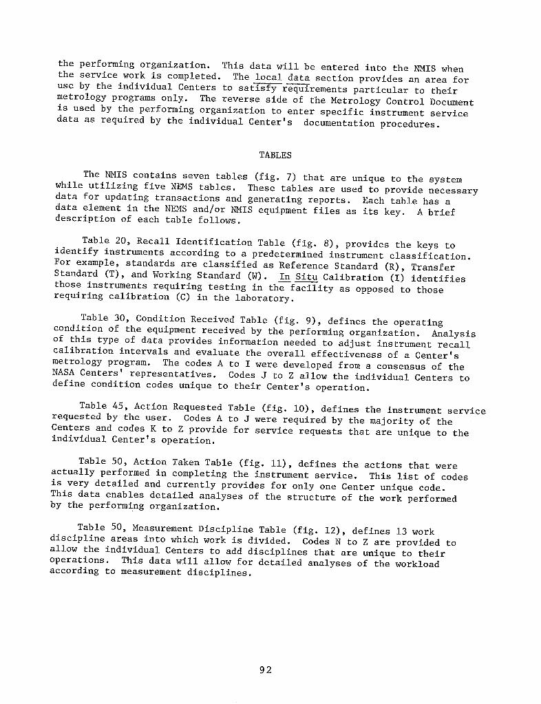
TABLES
The NMIS contains seven tables (fig. 7) that are unique to the system
while utilizing five NEMS tables. These tables are used to provide necessary
data for updating transactions and generating reports. Each table has a
data element in the NEMS and/or NMIS equipment files as its key. A brief
description of each table follows.
Table 20, Recall Identification Table (fig. 8), provides the keys to
identify instruments according to a predetermined instrument classification.
For example, standards are classified as Reference Standard (R), Transfer
Standard (T), and Working Standard (W). In Situ Calibration (I) identifies
those instruments requiring testing in the facility as opposed to thoserequiring calibration (C) in the laboratory.
Table 30_ Condition Received Table (fig. 9), defines the operating
condition of the equipment received by the performing organization. Analysis
of this type of data provides information needed to adjust instrument recallcalibration intervals and evaluate the overall effectiveness of a Center's
metrology program. The codes A to I were developed from a consensus of theNASA Centers' representatives. Codes J to Z allow the individual Centers to
define condition codes unique to their Center's operation.
Table 45, Action Requested Table (fig. i0), defines the instrument service
requested by the user. Codes A to J were required by the majority of the
Centers and codes K to Z provide for service requests that are unique to the
individual Center's operation.
Table 50, Action Taken Table (fig. ii), defines the actions that were
actually performed in completing the instrument service. This list of codes
is very detailed and currently provides for only one Center unique code.
This data enables detailed analyses of the structure of the work performed
by the performing organization.
Table 50, Measurement Discipline Table (fig. 12), defines 13 work
discipline areas into which work is divided. Codes N to Z are provided toallow the individual Centers to add disciplines that are unique to their
operations. This data will allow for detailed analyses of the workload
according to measurement disciplines.
92

Table 75, Performing Organization Table (fig. 13), provides identification
of the organization performing the work. For example, Code E identifies thatwork was performed on a Center's Reference Standards by the National Bureau of
Standards as opposed to those sent to a standards laboratory (Code D), or
another government laboratory (Code G). Codes I to Z are established as Center
unique to allow Centers having more than one identifiable calibration
laboratory to track individual performing organization performance. For
example, LaRC has eight organizations performing such work. This table also
includes calibration and repair labor rates for each of the codes to calculate
instrument and calibration repair costs.
Table 4_, Transaction Number Table (fig. 14), lists the transaction codes
identified for the operation of the NMIS.
The NEMS contains five tables used by the NMIS (fig. 15). However,
since the NMIS will not have a centralized data base, Table 252, NASA
Installation Number Table, will not be significant.
Table 40, Manufacturer's Code Table, contains codes assigned in the
Federal Cataloging Handbooks, H-4 series, identifying each manufacturer.
Additionally the code "XXXXX" is used when the manufacturer is known but the
code needs to be assigned and the code "ZZZZZ" is used when the manufactureris unknown.
Table 78, Custodian Account Number Table, contains the property custodian
account numbers and custodian numbers, names, mail codes, and organizational
codes required for property management.
Table 90, User Number Table, contains user numbers and names for
employees at each Center. Some Centers' table 90 will also contain names of
contractor employees.
Table 102, Building Number Table, contains the numbers and names of
buildings where equipment is located.
NMIS REPORTS
Through a coordinated effort of the workshop, 18 reports (fig. 16) were
developed to monitor instrument and calibration laboratory performance.
Since the detailed development began in October 1983, I0 additional reports
(fig. 17) have been developed. The frequency of individual issuance,
determined by consensus of projected Center usage, varies from a daily
generation to a yearly generation with nine reports issued by request only.
Additionally, if the standard frequency report issuance schedule does not
meet a particular Center's needs, provisions are made to easily change
the frequency.
A brief description of each report follows.
93

ECN Calibration Master List (Report 001).- This report lists, in
Equipment Control Number (ECN) sequence, all instruments contained in NMIS.
Each record shows ECN, item name, manufacturer's name, model number, date
calibration due, measurement discipline, performing organization for last
service, and recall identifier. Report prints total number of line items.
This report is generated quarterly and has no other selection criteria.
Calibration User List - ECN Sequence (Report 002).- This report lists
all instruments in the system sequenced by custodian account number, user
number, and ECN. Each record lists ECN, item name, manufacturer's name,
model number, date NASA acquired, calibration interval, date calibration due,
last eight condition received codes, measurement discipline, performing orga-nization for last service, and recall identifier. This report provides the
total number of instruments in each user account, each custodian account, andthe grand total. Other report selection criteria provided include user numberand custodian account number.
Calibration User List - Item Name Sequence (Report 003).- This reportcontains the same data as Report 002. However, it is sequenced by item name,
manufacturer's name, and model number as opposed to the ECN sequence of
Report 002. This report is issued on request only. No other selection
criteria is provided.
Calibration Item Name List (Report 004).- This report sequences the instru-
ments in the NMIS by item name and list manufacturer's name, model number, date
NASA acquired, ECN, custodian account number, user name, calibration interval,
last eight condition received codes, recall identifier, and date calibration
due. Additional selection criteria include item name, item name - manufacturer's
name, and item name - manufacturer's name - model number. This report lists
the total number of named instruments for each manufacturer, the total number
of named instruments and the grand total number of instruments. This report
is issued annually.
Calibration Model Number List (Report 005).- This report lists instrumentssequenced by model number, manufacturer's name, item name, and ECN. Itcontains manufacturer's name, item name, ECN, date NASA acquired, cost,
custodian account number, user number, calibration interval, last eight
condition received codes, recall identifier code, and date calibration due.Additional selection criteria include manufacturer's model number,manufacturer's name and manufacturer's name - model number. It lists the
total number of instruments for each model number and the grand total number
of instruments. This report is issued on request only.
Calibration Due List - ECN Sequence (Report 006).- This report lists bycustodian account number and user number those instruments due for calibration
and can be used as a calibration recall notice (fig. 18). The report issequenced by each custodian account and user number, date calibration due, and
ECN. This report contains item name, manufacturer's name, model number,
calibration interval, measurement discipline, and performing organization.
The report lists the total number of instruments due for each date, the total
94

number of instruments by both user and custodian account numbers and the grandtotal number of instruments due for calibration. Additional selection criteria
include date calibration due, date calibration due - custodian account number,date calibration due - custodian account number - user number. This report is
issued monthly.
Calibration Due List - Item Name SeQuence (Report 007).- This report
contains the same information as Report 006. However, it is also sequenced
by item name for each custodian account number and user number. Theadditional section criteria is identical to that of Report 006. This report
is issued on request only.
Calibration Due List - Performing Organization SeQuence (Report 008).- This
report lists the instruments due for calibration by performing organization
and is intended to be primarily used by performing organization managers. This
report is sequenced by performing organization, measurement discipline, itemname, date calibration due, manufacturer's name, and model number. The reportalso lists ECN and calibration interval. Additional selection criteria are
date calibration due and performing organization - date calibration due. This
report is issued monthly.
Calibration Overdue List (Report 009).- This report lists those instruments
which have not been submitted by a specified date and are overdue for calibration.
The report is sequenced by custodian account number, user number, date calibra-
tion due, and ECN. It contains the same information as Report 007. It lists
the total number of items overdue by user number, custodian account number,
and the grand total number of items overdue. Additional selection criteriainclude custodian account number - date calibration due and user number -
date calibration due. This report is issued monthly.
Performing Organization - Due/Overdue Status Report (Report 010).- Thisreport lists the instruments that have not been completed by a specified date.
This report is sequenced by performing organization, measurement discipline,
date required, and ECN. It also provides manufacturer's name and model number.
The report lists total instruments due for a given date, the total instrumentsdue/overdue for each measurement discipline and for each performing
organization. There is no other selection criteria. This report is issued on
a daily basis.
Hold Status Report (Report 011).- This report lists those instruments whichare not being actively processed in the performing organization's laboratory
for such reasons as shipped for off-site repair or awaiting repair parts.
This report is sequenced by performing organization, transaction date, and ECN.
The report lists item name, manufacturer's name, model number, measurement
discipline, and action taken code from Table 50. The report provides totalnumber of items for each transaction date, performing organization, and the
grand total number of items in the hold status. The additional selection
criteria is by performing organization. This report is issued monthly.
95
.... T

Calibra____tionSupport Analysis (Report 012).- This report provides a total
calibration and repair cost analysis in a year-to-date format and is sequenced
by custodian account number, user number, job order number, and ECN. Data
provided in this report include item name, labor costs, parts cost, outside
service cost, total cost, and date instrument was last serviced. The report
provides total cost by user number, custodian account number, and grand total
costs for each category. Additional selection criteria is by job order,
custodian account number, and user number. This report is issued annually.
Calibration Life Cycle Cost Analysis (Report 013).- This report provides
total service costs to date for each instrument. The report is sequenced by
item name, manufacturer's name, model number, and ECN. Data listed include
date NASA acquired, cost of item, labor cost, parts cost, outside service cost,
total cost, and average annual cost. Additional selection criteria include
item name - date NASA acquired, item name - manufacturer's name - date NASA
acquired, item name - manufacturer's name - date NASA acquired, item name -
manufacturer's name - model number - date NASA acquired, and date NASA
acquired - all. This report is issued annually.
Production Analysis (Report 014).- This report provides manpower datarequired for calibration, repair, and total service in hours to the nearest
0.i hours. The report is sequenced by performing organization, measurementdiscipline, item name, and model number. The report includes technician
identifier, ECN, manufacturer's name, calibration hours, repair hours, total
service hours, and date last serviced. The report provides both total hours
and total items by measurement discipline and performing organization.
Additional selection criteria is by performing organization. This report is
issued monthly.
Calibration Weekly. Status Report (Re_ort 015).- This report provides the
listing of the total number of items completed sequenced by performingorganization, measurement discipline, and ECN. The report lists manufacturer's
name, model number, initiate date, date calibrated, date last serviced,
action taken, and days late. The report provides, by performing organization,
the total number of items completed, the total number and percent of items
completed within a specified time frame. Additional selection sequence is by
performing organization only. This report is issued weekly.
Calibration Maintenance Time Analysis (Report 016).- This report provides
data describing the manpower required to service instruments sequenced bymanufacturer's name and model number. This report lists total instruments
calibrated, repaired, serviced; total calibration, repair and service hours;
and average calibration, repair, and service hours. The report also lists the
totals for these categories for each instrument manufacturer. Additional
selection criteria is by manufacturer's name, and manufacturer's name - model
number. This report is issuedannually.
96

Out of Tolerance and Inoperative Instrument Report (017).- This reportlists the instruments that were received in the calibration laboratory and
coded B, C, D, E, F, or G from the Condition Received Table (Table 30). This
report is sequenced by custodian account number, user number, condition
received code, item name, manufacturer's name, and model number. Other data
listed includes ECN, date NASA acquired, calibration interval, last eight
condition received codes, date calibrated, measurement discipline, and performingorganization for last service. This report lists the total number of out-of-
tolerance and inoperative instruments for each custodian account and useraccount and the total number of instruments received for these codes for a
specified month. Additional selection criteria includes custodian account
number - date NASA acquired, user number - date NASA acquired, date NASA
acquired - all, manufacturer's name - date NASA acquired, item name - date
NASA acquired, manufacturer's name - model number - date NASA acquired,manufacturer's name - item name - date NASA acquired. This report is issued
monthly.
Calibration Interval Analysis Report (Report 018).- This report provides
data for evaluating the effectiveness of a calibration interval determination
program for both calibration and limited calibration actions. The report liststhose instruments which were calibrated within +15 days of the scheduled date
and have condition received codes which identify instruments received in an
operating condition. The report lists the percentage of instruments receivedin tolerance for both calibration and limited calibration. This report is
sequenced by item name, manufacturer's name, model number, and calibration
interval. The report contains data including ECN and last eight conditionreceived codes. Additional selection criteria include item name - model
number, item name - manufacturer's name - date calibration due and all -
date calibration due. This report is issued annually.
Work Action Analysis Report (Report 019).- This report lists the instru-ments serviced by Action Taken Codes (Table 50) and provides a breakdown of
the type of work being performed. This report is sequenced by action taken,
performing organization, manufacturer's name and model number. The reportlists data including ECN, item name, last eight condition received codes,
total service hours, calibration interval, custodian account number, and user
number. The report lists the total number of items and service hours for each
performing organization and each action taken code. Additional selection
criteria includes action taken and performing organization. This report is
issued annually.
Property Location Report (Report 020).- This report lists the locationof each item and is sequenced by equipment location building, room, and ECN.
This report is different from a NEMS equipment location report in that italso includes the noncontrolled instruments while NEMS contains only
controlled equipment. The noncontrolled equipment has a metrology number
assigned to it for identification control only and not accountability. Datalisted include custodian account number, date calibration due, manufacturer's
name, model number, and item name. The report lists the total number of items
97

for each building. Additional selection criteria is equipment location building
and custodian account number. This report is issued on request only.
Work Action Analysis Report - Summary File (Report 021).- Since it is notmandatory that all instruments at a field Center be included in the NMIS, the
performing organization may be performing instrument service work that is not
included in any of the previous analysis reports. This report and Report 105
were created to record specific data in a summary format for uncontrolled
items. Report 021 lists by quarter the total number of items serviced for
each of the action taken codes. This report lists the previous quarter's
data when the second, third, and fourth quarter reports are issued. There is
no other selection criteria. This report is issued quarterly.
Metrology File Detail Item List (Report I00).- This report contains theentire data record to date for each instrument contained in NMIS. This report
lists all of the data elements identified as required for adequate metrology
system control. This report has no additional selection criteria and is
issued on request only.
Daily Transaction Report (Report lOl).-This report lists the daily trans-actions in the NMIS and is sequenced by transaction number and ECN. The report
also lists reference code, file data element, original entry and revised entry.
There is no additional selection criteria and the report is issued daily.
ERROR Codes and Messae__(Report I02).- This report lists all error codes
and error-code messages used in the NMIS. This report is sequenced by error-code and is issued on request only.
Global _Chan_e Report (Report 103).- This report lists the global changesentered into the system and is sequenced by data element number. The report
lists the changes from, changes to, data processed, reference code, and number
of records changed. There is no additional selection criteria and the reportis issued after each transaction and annually.
Metrol@gy Control Document (Report 104).- This report is the MetrologyControl Document which is the standard preprinted form for use in the NMIS.
Summary File Detail List (Report 105).- This report provides detailedinformation for those instruments not controlled by the NMIS but are serviced.
This report when combined with Reports 012, 014, and 016 will provide the
metrology manager with a more complete metrology system performance analysis.
This report is sequenced by performing organization and action taken. The
report summarizes data by action taken code such as repair hours, calibratehours, labor cost year to date, parts cost year to date, outside service cost
year to date, total number of instruments calibrated, total number of
instruments repaired, and total instruments serviced. Additional selection
criteria is by performing organization only. The report is issued quarterly.
98

Metrology Histor_ File Detail List (Report 106).- This report lists indetail all of the data elements required for an instrument record when stored
in the history file. This report is identical to Report i00. This report is
issued on request only.
CONCLUDING REMARKS
In 1982 the NASA Metrology and Calibration Workshop made the decision to
develop an agency-wide metrology data management system which would operate
in concert with the new NASA Equipment Management System (NEMS). The
metrology system would be used by field Centers to recall instruments for
periodic calibration, to evaluate instrument performance, to summarize and
report metrology work performance, and to provide other technical and manage-
ment data. Two meetings, at the Kennedy Space Center and the Jet PropulsionLaboratory, held in 1983 resulted in the development of the core data
elements--some shared with NEMS, some unique to the metrology system. Codes
for various work actions were adopted and applicable system tables developed.
In addition 18 system output reports were developed. Another of the major
accomplishments of these meetings was the preliminary design and adoption of
the Metrology Control Document (MCD) and the commitment that each field
Center would use it as a source document for the NASA Metrology Information
System (NMIS). The Langley Research Center was assigned lead responsibility
in the development of NMIS. During detailed development, over a period of
7 months, several additional data elements were identified, i0 additional
reports were developed, issuance frequency for reports was established, CRT
screen formatting completed, the MCD design completed, and the draft of the
NMIS design document compiled and distributed. Planned future activities
include a detailed Design Document Review by NASA metrologists at the Langley
Research Center (LaRC) in May 1984 and the initial system demonstration
scheduled for July 1984 at LaRC. The NMIS is scheduled for installation at
LaRC during the last quarter of calendar 1984 with second Center installation
initiated in January 1985. Installation plans for the other Centers will be
established at the next Metrology and Calibration Workshop to be held inOctober 1984.
99

NMIS/NEMS
Data Element Description
M-IO/E-10 * Equipment Control Number (ECN)
M-15/E-12 Old Tag Number
M-90/E-200 * Labor Cost Last Service
M-95/E-202 * Labor Cost Year to Date
M-IO0/E-204 * Labor Cost to Date
M-105/E-210 * Parts Cost Last Service
M-IIO/E-212 * Parts Cost Year to Date
M-II5/E-214 * Parts Cost to Date
M-120/E-222 * Date Last Serviced
M-125/E-230 * Date Calibrated
M-130/E-232 * Date Calibration Due
M-135/E-30 * Item Name
M-140/E-40 Manufacturer's Code
M-145/E-42 * Manufacturer's Name
M-150/E-44 * Manufacturer's Model Number
M-155/E-46 * Manufacturer's Serial Number
M-160/E-60 * Date NASA Acquired
M-165/E-72 * Acquisition Document Control Number
M-170/E-78 Custodian Account Number
M-175/E-80 * Custodian Number
M-180/E-86 * Custodian Organization Code
M-185/E-90 * User Number
M-190/E-102 * Equipment Location Building
M-195/E-104 * Equipment Location Room
M-210/E-150 * Acquisition Cost
*Indicates identified by metrology workshop.
Figure i.- NEMS data elements required by NMIS.
i00
r .......

NMIS
Data Element Description
M-20 Recall Identifier
M-25 Recall Entry Date
M-30 * Condition Received
M-35 * Technician Identifier
M-40 * Calibration Interval
M-45 * Action Requested
M-50 * Action Taken
M-55 * Initiate Date
M-56 Transaction Date
M-57 Date Required
M-60 * Repair Hours
M-65 * Calibrate Hours
M-70 * Measurement Discipline
M-75 * Performing Organization
M-80 * Date Repaired
M-85 * Outside Service Cost Last Service
M-86 * Outside Service Cost Year to Date
M-87 * Outside Service Cost to Date
M-166 Job Order Number
M-200 Date Loaned Out
M-205 Date Loaned Due In
M-400 Reserved for Local Data
M-410 Reference Code
M-420 Transaction Number
*Indicates identified by metrology workshop.
Figure 2.- NMIS unique data elements required.
i01

NASA CALIBRATION
IIHIfllllJHIrllJrfllfmffllrlC00138
Figure 3.- NMIS instrument identification tag.
102

METROLOGY CONTROL DOCUMENT
- ]1. ITEM NAME 2. MANUFACTURER 3. EQUIP. CONTROL NO.
z_(2
4. MODEL NO. 5. SERIAL NO. 6. USER NAME ! ?. USER ID.
I8, BLDG. NO. 9, ROOM NO, 10. CUSTODIAN NAME tl. CUS. NO. 12. CUS. ORG. 13. OLD TAG NO. t4, DATE CALIBRATION DUE
i
I. ACQ. DATE 2, ACQUISITION COST _ 3. ACQUSITION DOCUMENT NO. 4. CAL. INTI 5. REC. ENTRY 6mDATE LAST SERV.
I DATE
COST 7. LAST 8. YEAR TO g. TOTAL TO 10. I1. ACTION TAKEN LAST x TIMESSERVICE DATE DATE CONDITION RECEIVED LAST x lIMES
LABOR
PARTS 12. REP. ItRS.
LAS,T,MES I I. 1 I I,, , ,,
OUTSIDE 13. CAL. HRS.
SERVICE LAST x T,MES [ [ I,,, ,,
I. DATE REG. 2. ACT. RE(}. 3. WORK AREP 4. JOB ORDER 5. INTITIATE DATE _T.M. APPROVALI--=c_
i,u(._ 7, REMARKS
I. JOB'PRIORIT_ 2. ACT. REQ. ACT. TKN. 4. CONO. REC. 5. REP. HRS. 6. CAL, IIRS 7. TOTAL HRS. 8. PARTS COST 9. REP. DAlE 10. CAL. DATE
/ i g
11. CAL. TECH. 12. REP. TECH t3. OUTSIDE SERVICE COST -I4.'DATE REC. 15. REMARKScc
_ .......
o:_ 16. LOCALDATAg_-nz
u
Figure 4. NMIS Metrology Control Document - Front Side

,,. OU, M NTCO TRO'NO.1'81 ACCEiSOR'ES ECE'VEOA. POWER CORD C, PROBES E. COVER
B. MANUAL D, LEADS F. OTHER
19. STANDARDS _ TEST EQUIPMENT USED
A. IDENFITICATION NO. El. CAL. DUE DATE A. IDENTIFICATION NO. S. CAL. DUE DATE A. IDENTIFICATION NO. B. CAL. DUE DATE
11
20. ENTER OUT OF TOLERANCE VALUES ONLY
A. Ft. C. D. E. TOLERANCETEST IDENTIFICATION FUNCTION TESTED NOM. VALUE INITIAL VALUE
LOW HIGH
21, PARTS REPLACED 22. 23.DATE TO AWP DATE PARTS RECEIVED
I-_ A. SYMBOL Ft. PART NO, C. SOURCE D. UNIT COST E. QUANTITY F. TOTAL COSTO .....
24. REMARKS G. GRAND TOTAL COST _1_
Figure 5. NMIS Hetrology Control Document - Back Side

INSTRUCTIONS FORMETROLOGy CONTROL DOCUMENT
•_NOTE_ Al£ dates, machine generated o_ hand written, are presented as MMDDYy*_USER INFORmaTION: 1--14 are preprinted upon form generation.BACKGROUND INFORMATION: 1--13 are preprinted upo_ form generation.
USER-TM: (TM = technical monitor) User completes 1,2,5, and 8. TM completed 3,4, and 6, makes any necessary changes to 1,2,5, and 8, and certifiesapproval by signing 7.
2. ACTION REQUIRED CODES 4. WORK AREA CODES
"A" = acceptance test "G" - maintenance "A" - acoustics, vibration, shock "I" = ionizing radiation"B" = special test "H" - modify "B" = pressure & vacuum "J" - microwave & RF
"C" = calibration "I" - repair "C" = chemical & analytical "K" - oscilloscopes, waveform,"D" = decontaminate/clean "J" - other "D" - dimensional video & communications
"E" - limited calibration "K thru Z" center unique "E" - electrical/elect_onlc "L" = liquid & gas flow"F" = functional check & maintained "F" - frequency stde. & counters "M" _ mass, force, & torque
"G" = radiometry & photometry "N thru Z" center unique &"H" - temperature & humidity maintained
CALIBRATION-REPAIR INFORMATION: 1 -- 15 completed by appropriate personnel in servicing organization or as local options dictate.
5,6,7 -- complete to XX.X manhours.8 -- rounded to whole dollars from block 21- G.13 -- rounded to whole dollar.
3. ACTION TAKEN CODES 4. CONDITION RECEIVED CODES
"A" = acceptance test "N" R modified "A" = operative-in tolerance"B" = special test "O" _ other "B" = operative-out of tolerence _IX"C" - calibrated "P" - adjusted-limited calibration "C" = operatlve-out of tolerence >IX _2X
___ "D" = decontaminatedcleaned "Q" - adjusted-callbrated "D" = operative-out of tolerence >2X 54Xo "E" = center unique "R" - repaired "E" = operative-out of tolerence >4X_n "F" - functional check "S" - repalred-limited calibration "F" - operative-out of tolerence indeterminable
"G" _ shipped for off site repair "T" - repalred-calibrated "G" - inoperative"H" = hold (AWP, manuals, etc.) "U" - clean-adjust-limited calibration "H" - not determined/applicable"I" - returned to user unserviced "V" - clean-adjust-calibrate "I" = other-see remarks
"J" - reject-beyond economical repair "W" - clean-llmited calibration "J thru Z" center unique & maintained"K" - reject-shipped for off site repair "X" - clean-calibrate"L" - limited calibration "Y" - clean-calibrate
"M" = maintenance "Z" = clean-repair-calibrate
LOCAL DATA: This section may be used, at local option, for any purpose desired. Any required programming is local responsibility.REVERSE: General instrument service information. This section will be completed by servicing organization or as local procedures dictate.
Block 17 -- Equipment Control Number must be completed manually.
Figure 6.- Instructions for completing Metrology Control Document.

Table Number Table Name
20 Recall Identification Table
30 Condition Received Table
45 Action Requested Table
50 Action Taken Table
70 Measurement Discipline Table
75 Performing Organization Table
420 Transaction Number Table
Figure 7.- NMIS tables required
Code Description
C Calibration
F Functional test
I In situ calibration
N Non recall
P Preventive maintenance
R Reference standard
S Personal safety
T Transfer standard
W Working standard
Figure 8.- NMIS recall identification codes--Table 20.
106

Code Description
A Operatlve - in tolerance
B Operative - out of tolerance _ ix
C Operative - out of tolerance > ix < 2x
D Operatlve - out of tolerance > 2x < 4x
E Operative - out of tolerance > 4x
F Operative - out of tolerance - indeterminable
G Inoperative
H Not determined - not applicable
I Other - see remarks
J-Z Remaining values Center unique and maintained
Figure 9.- NMIS instrument condition received codes--Table 30.
Code Description
A Acceptance test
B Special test
C Calibration
D Decontaminate/clean
E Limited calibration
F Functional check
G Maintenance
H Modify
I Repair
J Other
K-Z Remaining values Center unique and
maintained
Figure i0.- NMIS action requested codes--Table 45.
107

Code Description Code Description
A Acceptance test N Modified
B Special test 0 Other
C Calibrated P Adjusted - limited calibration
D Decontaminated - cleaned Q Adjusted - calibrated
E Center unique R Required
F Functional check S Repaired - limited calibration
G Shipped for off-site repair T Repaired - calibrated
H Hold (awaiting parts, manuals, etc.) U Cleaned - adjusted - limited calibration
I Returned to user unserviced V Cleaned - adjusted - calibrated
o j Reject - BER (beyond economical repair) W Cleaned - limited calibration
K Reject - shipped for off-site repair X Cleaned - calibrated
L Limited calibration Y Cleaned - repaired - limited calibration
M Maintenance Z Cleaned - repaired - calibrated
Figure ii.- Action taken codes--Table 50.

Code Description
A Acoustics, vibration, shock
B Pressure and vacuum
C Chemical and analytical
D Dimensional
E Electrical/Electronic
F Frequency standards and counters
G Radiometry and photometry
H Temperature and humidity
I Ionizing radiation
J Microwave and RF
K Oscilloscopes, waveform, video, and communications
L Liquid and gas flow
M Mass, force, and torque
N-Z Remaining values Center unique and maintained
Figure 12.- NMIS measurement discipline codes--Table 50.
Code Description
A Calibration/repair laboratory
B Repair laboratory
C Calibration laboratory
D Standards laboratory
E National Bureau of Standards
F NBS map
G Government primary laboratory (other than NBS)
H NASA map
I-Z Remaining values Center unique and maintained
Figure 13.- NMIS performing organization codes--Table 75.
109

Transaction Number Transaction Name
Ol Receipt of New Instrument by Inspecting Facility
02 Receipt of New Instrument by Receiving Facility03 Receive Instrument for Recall
04 Return of Record from History File
05 Retagging
33 New Performing Organization34 Send to Calibration
35 Send to Service
36 Return from Calibration
37 Return from Service
38 Cost (change)
39 Custodian Account (change)
40 User Number (change)
41 Instrument Location (change)42 Loan Pool Out
43 Loan Pool Returned
44 Record Data (change)45 Global (change)
46 Calibration Interval Adjustment
47 Factory Repair/Service48 Recall Identifier
66 Modify Performing Organization
67 Lost Tag
68 Excess (broken)
69 Decontrol (removal of tag)
99 Discontinue Performing Organization
Figure 14.- NMIS transaction number codes--Table 420.
Table Number Table Name
40 Manufacturer's Code Table
78 Custodian Account Number Table
90 User Number Table
102 Building Number Table
252 NASA Installation Number Table
Figure 15.- NEMS tables used by NMIS.
Ii0

ReportNumber Report Name Frequency
001 ECN Calibration Master List Quarterly
002 Calibration User List - ECN Sequence On Request
003 Calibration User List - Item Name Sequence On Request
004 Calibration Item Name List Annually
005 Calibration Model Number List On Request
006 Calibration Due List - ECN Sequence Monthly
007 Calibration Due List - Item Name Sequence On Request
008 Calibration Due List - Performing Organization Sequence Monthly
009 Calibration Overdue List Monthly
010 Performing Organization Due/Overdue Status Report Daily
011 Hold Status Report Monthly
012 Calibration Support Analysis Annually013 Calibration Life Cycle Cost Analysis Annually
014 Production Analysis Monthly
015 Calibration Weekly Status Report Weekly016 Calibration/Maintenance Time Analysis Annually
017 Out-of-Tolerance and Inoperative Instrument Report Monthly
018 Calibration Interval Analysis Report Annually
Figure 16.- NMIS reports developed by metrology workshop.
ReportNumber Report Name Frequency
019 Work Action Analysis Report Annually
020 Property Location Report On Request
021 Work Action Analysis Report - Summary File Quarterly
i00 Detail Item List On Request
i01 Daily Transaction Report Daily
102 Error Codes and Messages On Request
103 Global Change Report Annually
104 Metrology Control Document On Request
105 Summary File Detail List On Request
106 Metrology History File Detail List On Request
Figure 17.- Additional NMIS reports required.
iii

NATIONAL _UTICS AND SPACE ADMINISTRATION
REPORT NOz 006 INSTALLATION NAME PAGE ZZ9NASA METROIDGY INFORMATION SYST_4 RUN DATE MM/DOIYY
BY: CUSg0DIAN _USER NI3qBER CALIBRATION DUE LIST - ECN SE_DATE CALIBRATION DUEECN
CUSTODIAN ACCOUNT NUMBER, NAME, M/S: XXXXX, _, XXXXXXXUSER _, NAME, M/S: XXXXXX, _, XXXXXXX
DATE MANUFA_' S CAL MEAS PERFCAL DUE ECN ITeM NAME MANUFACTURER'S NAME MODEL NUMBER INT DISC ORG
999999 XXXXXX _ _ XXX_ 99 X X
after change in Date Calibration Due: I. Sequence: Custodian Account Number (M-170)User Number (M-185)
TOTAL NUMBER OF _ DUE: ZZ,ZZ9 Date Calibration Due (M-130)ECN (M-10)
after change in User Ntm_er:
2. Page Break: User NumberTOTAL NUMBER OF IT£MS: ZZ,ZZ9 Custodian Account Number
Max/mum Number of Lines Per Pageafter change in custodian Account Number:
3. Section Break: Date Calibration Due
TOTAL NUMBER OF IT_4S: ZZ,ZZ9_o 4. Total Level: for Date Calibration Due
for User NumberGRAND TOTAL NUMBER OF _: ZZ,ZZ9 for custodian Account Number
Grand Total
5. Selection Criteria: Date Cal Due
Date Cal Due/Custodian Account Number
Date Cal Due/Custodian Account Number/User Number
All
6. Distribution:
7. Frequency: Monthly
Figure 18.- Format of instrument calibration due report.