Embed Size (px)
Citation preview

Ideas and strategIes In Product develoPment
NASA Develops Wireless Sensors to
Detect Lightning Strike Damage to
Composite Aircraft
Winter/Spring 2015 | An Publication
Developing Power Tools with Simulation
Innovating Better Products with Optimization Tools
Keeping JSF Pilots Cool in the Cockpit
editorial directorBeverly [email protected]
PublisherMichael J. [email protected]
media services managerSam Schulenberg [email protected]
creative directorCavedweller [email protected]
audience development managerMaria [email protected]
Concept To Reality is published semi-annually for Altair Engineering, Inc. by Penton Marketing, a unit of Penton.
1300 E. 9th StreetCleveland, OH 44114-1503
subscription services To subscribe to Concept To Reality, visit www.C2Rmagazine.com/subscribe
Send address changes to:Beverly BeckertPenton1300 E. 9th StreetCleveland, OH 44114-1503
© 2015 Altair Engineering, Inc. All rights reserved.
All trademarks, company names and product names referred to throughout this publication are the properties of their respective companies. All rights reserved.
1820 E. Big Beaver RoadTroy, MI 48083-2031www.c2rmagazine.com
Printed in the U.S.A.
HyperWorks Unlimited®
Innovation Intelligence®
Fully managed HPC cloud appliances for CAE
Visit altair.com/cloud to learn more about simulating in the cloud with Altair.
• Unlimited use of Altair’s HyperWorks CAE suite• Pre-packaged, fully-configured, no IT support required• Single pane of glass, secure access to HPC resources• Dynamic scalability to support varying CAE demand• Simulate anywhere – remote modeling, analysis, visualization• Value-based, pay-for-use model for small and large enterprises
HyperWorks Unlimited Physical Appliance
HyperWorks UnlimitedVirtual Appliance
Altair_Cloud-C2R_Advert_032017_03.indd 1 3/20/15 3:23 PM

Contents
ad Index
FeaturesSimulation Powers Development of Professional Power ToolsCAE is a core element in developing high-end, long-lasting professional power tools at DeWalt, a Stanley Black & Decker brand.
NASA Develops Wireless Sensors to Detect Lightning Strike Damage to Composite AircraftComputational electromagnetic software enables a team of researchers at NASA’s Langley Research Center to develop wireless resonant sensors that can measure and mitigate lightning strike damage to composite aircraft.
Chiller Unit Keeps Joint Strike Fighter Pilots CoolA model-based embedded development system enables AMETEK to design, simulate, create firmware for and validate a chiller unit control system.
Optimization Technology: Leveraging a Solid Foundation to Innovate Better ProductsFor more than 20 years, steady improvements in the OptiStruct solver platform have enabled users in a range of industries to tackle increasingly complex design challenges.
departmentsLETTER FROM THE CEO:
Coupling Topology Optimization with 3D Printing Can Spur Design Innovation3D printing’s symbiosis with topology optimization enables greater creative expression while maintaining structural integrity and performance attributes.
IN THE NEWS
Stay up to date on Altair’s latest activities
IFC .........................................................................Altair
3 ..............................................................solidThinking
7 ......................................................................FEMFAT
15 ....................................................................... Fluidon
IBC .......................................................................Cradle
BC ..........................................................................Altair
WInter/sPrIng 2015 | CONCEPT TO REALITy | 1
Winter/spring 2015
04
08
12
16
02
19
04
12
08 16

2 | CONCEPT TO REALITy | WInter/sPrIng 2015
Letter from the CEO
WJames R. ScapaChairman and CEO, Altair
With today’s rapid advancements in additive manufacturing (commonly known as 3D printing), the manufacturing industry is on the cusp of an innovation explosion. This shift promises to challenge our conventional thinking and practices and even revolutionize how we pro-duce products and how we design.
For the design and engineering community, this will mean fewer and some different creative limitations inherent with traditional manufac-turing methods. To fully realize the potential of additive manufacturing, a fundamental rethink-
ing of the development process is required to take advantage of the enormous design freedom it offers. Never before has simula-tion, especially topology optimization, been more relevant to the design community, allowing development of the most innovative, lightest weight products of our time.
Forward-thinking com-panies have long employed
topology optimization to create innovative, light-weight, and structurally efficient concepts. It is particularly well-suited for use with 3D printing, since topology optimization tends to create free-form, organic structures that are often difficult to construct in their literal form using traditional manufacturing methods. 3D printing offers symbiosis with topology optimization, enabling greater creative expression while maintaining structural integrity and performance attributes.
Over the past 20 years, Altair has pioneered and globally led the advancement of topology optimization technology. Delivered through our OptiStruct® and solidThinking Inspire® software brands, our technology allows designers and engineers to discover completely new shapes to meet aggressive packaging, lightweighting and structural performance objectives. 3D printing provides new opportunities to fully explore the design space – unconstrained – for even greater savings and increased performance.
For example, a unique capability of 3D print-ing lies in its ability to manufacture hollow shapes with complex external geometry using tiny cells known as lattice structures. OptiStruct now extends topology optimization to assist in the efficient blending of solid-lattice structures with smooth transitional material volume.
To enable more efficient data transfer for pro-duction, Altair is working closely with several software and hardware partners – including most of the 3D printer equipment manufacturers – to accommodate various requirements of the 3D printing process.
We invite you to learn more about Altair’s technology to support 3D printing – and how it can improve design innovation – by visiting www.altair.com/3Dprinting. To see how the stra-tegic use of simulation can drive performance, quality and efficiency in product development, please enjoy the applications shared in this issue of Concept To Reality.
coupling topology optimization with 3d Printing can spur design Innovation
3D printing’s symbiosis with topology optimization enables
greater creative expression while maintaining structural integrity and
performance attributes.

Design for the Freedom of Additive Manufacturing
What if you could start your design process with the ideal structural part and then use the freedom of additive manufacturing to make that part a reality? With solidThinking Inspire®, this is now possible.
An Company© 2015 solidThinking, Inc. All Rights Reserved.
Learn more at solidThinking.com/InspireC2R

S
4 | CONCEPT TO REALITy | WInter/sPrIng 2015
design strategies
Since the invention of the first hand-held power tools more than 100 years ago, the industrial power tool industry has evolved to a very competitive and challenging market. There is a high and increasing demand for long-lasting quality tools offering power, quality and safety. These tools are used under the harshest conditions and are expected to work without any performance loss over years with little maintenance. Global and regional competition to build better tools is very high. Because of the long life cycle of power tools, a short time to market with new advancements is important for brand loyalty and staying ahead of the competition.
DeWalt, a Stanley Black & Decker brand, is a leading manu-facturer of industrial/professional power tools with more than 300 power tools and equipment products as well as 1,000 power tool accessories, including corded and cordless drills, saws, hammers, grinders, routers, planers, plate joiners and sanders as well as lasers, generators, compressors, and nailers, among others. DeWalt tools can be found wherever tools are sold, globally.
The DeWalt brand has three development sites – one in the United States, one in China and one in Germany. The German development site in Idstein designs, develops and manufactures hammer drills for the DeWalt brand, handling everything from the initial concept to the engineering and the manufacturing. A team of engineers executes the simulation/computer-aided engineering (CAE) tasks, collaborating closely with the hammer drill design teams at the Idstein facility.
cae Increases global competitiveness
Eight years ago, the DeWalt engineers took a major step to expand the use of CAE technology within their estab-lished product development process. During the learning and early adoption phases, CAE was not relied upon heav-ily within DeWalt’s mature, proven development cycle. Since then, staff expertise and organizational confidence have grown
By Evelyn Gebhardt
CAE is a core element in developing high-end, long-lasting professional power tools at DeWalt, a Stanley Black & Decker brand.
simulation Powers development of Professional Power tools
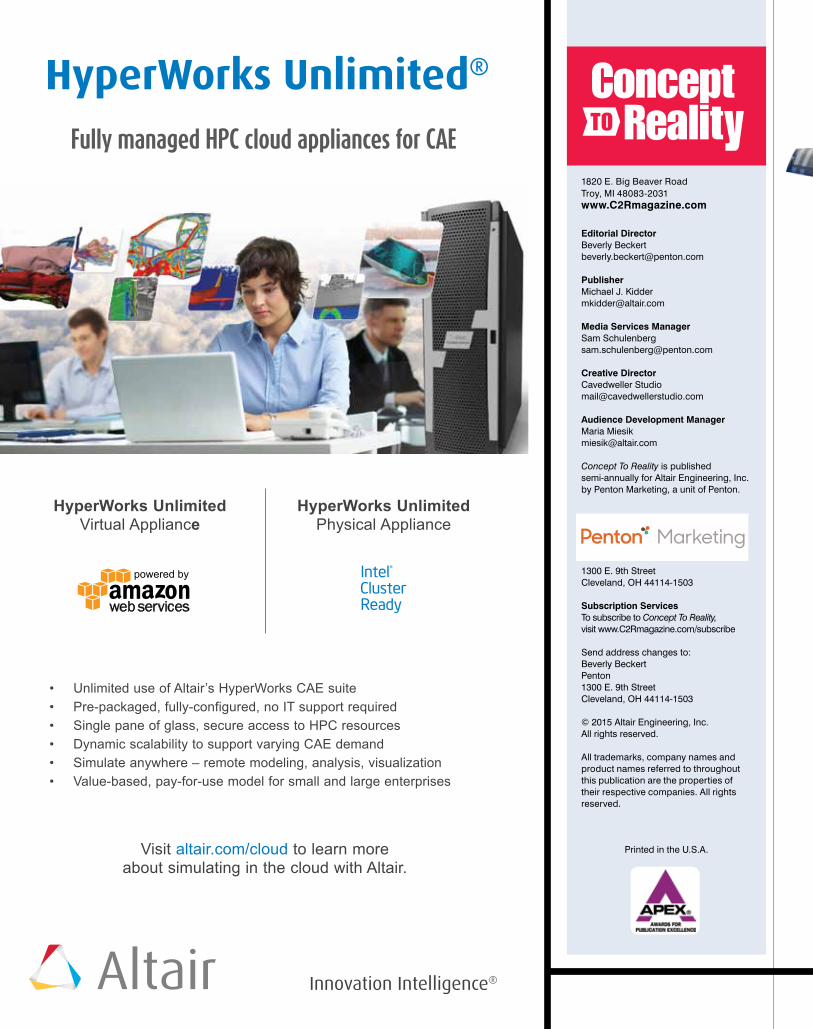
DeWalt, a Stanley Black & Decker brand, is a leading manufacturer of indus-trial/professional power tools such as this jackhammer. The company relies on CAE technology within its product development process to optimize its tools.
WInter/sPrIng 2015 | CONCEPT TO REALITy | 5
significantly, and CAE is now a fully integrated, mainstream activity in DeWalt’s hammer drill devel-opment process.
One of the first Altair CAE tools Stanley Black & Decker/DeWalt German engineers started to use was HyperMesh®, a finite-element pre-processing software. Part of Altair’s HyperWorks® CAE suite, HyperMesh is used for tasks such as meshing and model setup. Later, other HyperWorks’ tools followed, among them HyperStudy® for optimization tasks; HyperView® for post-processing; and RADIOSS®, OptiStruct®, MotionSolve® and AcuSolve® for solving explicit and implicit finite-element analyses, multi-body dynamics and fluid problems.
To accelerate its development process while ensuring an unwavering commitment to quality and performance, espe-cially for the high-end DeWalt product line, Black & Decker started to ramp up its own CAE department at the DeWalt site in Germany.
“The company realized that it had to start using virtual development tools more and that it needed to implement new development methods, extending traditional practices based on experience and physical tests,” says Andreas Syma, direc-tor of Global CAE for DeWalt power tool development. “With the competition we face, especially in hammers, and the strong pressure to reach market maturity as early as possible while keeping all of our quality standards for professional tools as high as possible, Stanley Black & Decker had to enhance its development processes,” he explains. “As a first step, we imple-mented advanced CAE methods within Dewalt’s development process of hammer drills in Germany. With the success of the CAE methods and the development processes created, we are now beginning to implement these throughout Stanley Black & Decker Inc. for the development of various power tools.”
Today, the Idstein CAE team is using the entire HyperWorks suite for almost all CAE-related tasks and has also started to implement tools of the Altair Partner Alliance (APA) – a program that provides Altair customers access to third-party partner solutions through Altair’s unique unit-based software licensing system. Through the APA, DeWalt engineers use FEMFAT and DesignLife for fatigue analysis as well as DSHplus in combination with MotionSolve for complex hydraulic and pneumatic systems co-simulation.
Syma notes, “I can point out three reasons why we work so extensively with Altair and its solutions. First, there is the licensing system – this is really unique in the market. You have a pool of license units you can use for every application offered under the licensing agreement.
“The second reason,” says Syma, “is Altair as a company itself. Altair really is an engineering company. Most of its employees are engi-neers, and when we talk to them, we always know that we are talk-ing to experts who understand us, our challenges and our needs, not only as simulation and software experts but also as engineers. We regularly hold meetings with the German Altair team in Cologne, and I can say that both parties ben-efit from these technology-driven meetings. We give them input about new things we tested to help them improve the software, and we receive their support in using the soft-ware without opening a new project for every request – all included in the license fee for the software.
“Another important reason why we work with Altair and its solu-tions,” continues Syma, “is that Altair offers an entire suite of CAE tools. If you also consider the Altair Partner Alliance program, you are able to handle almost every development task with HyperWorks and its partner tools, including multi-physics and co-simulation aspects.”
automation ensures unwavering Quality
Syma describes that a regular use of the HyperWorks suite is to simu-late the power tool drop test – a very common event experienced through-out the service life of any hand-held power tool. For the virtual drop test, the engineers use HyperWorks to streamline the modeling, analysis and results visualization for multiple drop orientations to predict resulting damage in order to take corrective steps earlier in the design phase to minimize failures in the field and warranty claims. Following drop test-ing, a power tool has to comply with set high-quality standards, i.e. noise and vibrations. In addition, it must demonstrate no structural damage and be electrically safe.
Detailed cutaway view of Dewalt’s hammer drill finite-element model developed using HyperMesh®.
MODELING
Hammer drill impact transfer and penetration analysis using RADIOSS®.
IMPACT ANALySIS
Drill hammer gear housing struc-tural analysis for assembly and operating loads using OptiStruct®.
ANALySIS AND OPTIMIZATION
Drill hammer airflow simulation using AcuSolve®.
CFD ANALySIS
6 | CONCEPT TO REALITy | WInter/sPrIng 2015
design strategies
With the virtual drop test, engineers can quickly realize any weak points and improve the design until it fulfills all qual-ity aspects. Since the CAE engineers work closely with the design teams, iterations can be carried out very quickly and easily at a fraction of the cost and time needed for the same number of physical tests.
DeWalt engineers have also adopted the use of Altair’s optimization technology very early in their new product development pro-grams – even before the design is made. One example of how DeWalt engineers are using this method, more commonly known as sim-ulation-driven design, is in the development and optimization of hammer mechanisms.
The hammer mechanism is a critical component of a drill hammer and com-bines a lot of engineering competencies. Together with Altair, Syma’s team defined a parametric model – a parametric structural mesh created by applying Altair’s morphing technology. By using design of experiments (DOE) and optimization methods, the
engineers then automatically analyzed vari-ous variations of the geometries to see which design offered the best hammer mechanism performance.
“The implementation of a CAE-driven design process,” explains Syma, “really changed our way of developing new prod-ucts. It helped us to test various designs very quickly and to find the global optimum. We defined the design space and applied bound-ary conditions, i.e. load cases. The CAE tools then helped us to find an optimized design with the best possible performance. In a weekend, we can now calculate several hun-dred different model variations and create thousands of results, which we post-process automatically, to know in which direction we have to fine-tune development.”
One of the major reasons to automate development processes of professional high-performance tools is the strong competition in this market. Syma says, “Our products have always been very good: they have a long lifetime, are durable and powerful. But if you
Stanley Black & Decker (SBD) is consis-
tently seeking ways to maintain a
competitive edge and bring better-per-
forming products to market faster. One
way the industry leader has learned it can
accomplish these goals is by leveraging
simulation-based optimization early in the
design process. By running simulation
software on a high-performance comput-
ing (HPC) platform, engineers can test
several hundreds of designs at a time and
gain new insights into product perfor-
mance, durability, cost and weight.
Previously, SBD had been using
workstations running LS-DyNA, with an
optimization runtime of about three weeks.
But this runtime was not sufficient to stay
competitive – SBD’s goal was to turn
around a job over a weekend (i.e. less than
three days).
SBD understood that it needed more
computational power to meet its goals but
was reluctant to invest in more hardware or
compute cores. The company was
concerned not only about the additional
cost of the HPC resources but also about
the effort to maintain and support a
complex HPC system, as well as the ability
to fully leverage the hardware with the
necessary software licenses to keep
utilization high.
SBD secured bids from three leading
HPC hardware providers, but the proposed
solutions did not allay their cost and
complexity concerns. SBD then reviewed
HyperWorks Unlimited®, a private cloud
computing solution from Altair. This
turnkey appliance includes pre-configured
HPC hardware and software – with
unlimited use of all HyperWorks applica-
tions plus PBS Works for HPC workload
management.
The SBD team ran a benchmark study
that proved RADIOSS and HyperStudy
from Altair would be equivalent in accuracy
and performance to their current
LS-DyNA/optiSLang solution. SBD then
moved forward with the HyperWorks
Unlimited solution, choosing a 160-core
system that Altair delivered and installed in
just a few days.
HyperWorks Unlimited provides
numerous benefits including:
• Comprehensive CAE suite with fast,
powerful solvers
• Pre-configured HPC system fully
managed by Altair
• Major cost savings over traditional
hardware or software purchase
SBD now takes advantage of
HyperWorks Units for unlimited use of all
HyperWorks and PBS Works software
within the appliance, supporting massive
virtual exploration. By leasing the
HyperWorks Unlimited appliance, SBD
also shifts its HPC investment from a
capital expense to an operational expense.
In addition, SBD deals with a single
vendor: Altair fully supports the hardware
and software, from deployment to ongoing
maintenance and support throughout the
contract period.
HyperWorks Unlimited HPC Appliance Improves the Capacity for Innovation
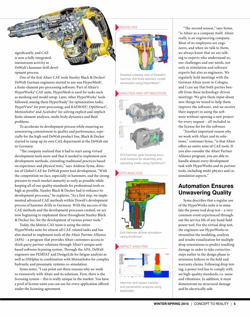
DeWalt engineers apply co-simulation to improve the performance of products using Altair’s OptiStruct® topology optimization and MotionSolve® multi-body dynamics analysis technologies. Redesigning this connecting rod using co-simulation resulted in a 25% reduction in maximum stress level and a lighter weight product.

WInter/sPrIng 2015 | CONCEPT TO REALITy | 7
don’t improve your development processes and reach a faster time to market, the com-petition may catch up. If you want to be a leader in this market, you have to apply vir-tual development tools and methods. If not, you won’t stay in the top list of professional tool providers. This is not only valid for drill hammers but also for angle grinders, drills, nailers and impact wrenches. In addition we have to offer the tools at a competitive price, which means that we have to develop faster and to consolidate development costs.
“Due to these reasons,” continues Syma, “I see the importance of CAE in innova-tive product development, especially in our industry, constantly increasing. The intensive and automated use of CAE tech-nologies is the right way to go. In the long run, we’ll be able to decrease the amount of prototypes. Already, we see shorter devel-opment cycles in our product development, and we sometimes get a design right at our first development attempt. Each tool that
is available earlier within the shops can be bought sooner. This increases our revenue and adds to our success.”
Future developmentIn a highly competitive market such
as the industrial power tool market, the importance of virtual development methods and the use of dedicated CAE technologies strongly increase. To handle cost-effective development of these complex products, the implementation of CAE-driven design pro-cesses is almost mandatory.
Stanley Black & Decker has seen the benefit CAE tools bring to their develop-ment process at DeWalt Germany and will apply the methods now at their other development sites. Since last October, Syma is now responsible for all DeWalt CAE departments worldwide – bringing the suc-cessful process he and his team developed in Germany to DeWalt’s other professional
high-performance power tools.“For me,” Syma concludes, “Altair’s offer-
ing of an entire suite for CAE applications is the best solution available in the market to support innovative product development. It includes close to everything we need on a very high level and all under one licensing system – from pre-processing to optimiza-tion tools and solvers to post-processing. With the recent deployment of Altair’s new CAE high-performance computing appli-ance, HyperWorks Unlimited, HyperWorks really is the best solution for our organiza-tion to cost-effectively scale to handle the varying, complex simulation requirements across our entire product portfolio.”
Evelyn Gebhardt is a contributor to Concept To
Reality magazine.
For more information on HyperWorks and HyperWorks Unlimited, visit www.c2rmagazine.com/2015
Fatigue Analysis Software
FEMFAT (Finite Element Method Fatigue) performs fatigue analyses in combination with all leading finite element pre-processors and solvers.
• Fast and flexible fatigue life prediction• Multiple joint type assessment• Open database concept (materials, joints)
10-12 June 2015Steyr, Austria
10th
InternationalFEMFAT
User Meeting
www.femfat.com
2014-11_Femfat_Inserat_Altair_Final.indd 1 12.12.2014 12:30:29
S
8 | CONCEPT TO REALITy | WInter/sPrIng 2015
the art of Innovation
By Beverly A. Beckert
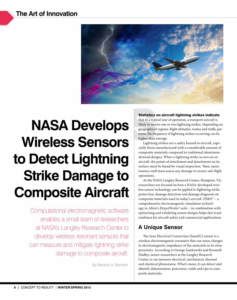
Statistics on aircraft lightning strikes indicate that in a typical year of operation, a transport aircraft is likely to receive one or two lightning strikes. Depending on geographical regions, flight altitudes, routes and traffic pat-terns, the frequency of lightning strikes occurring can be higher than average.
Lightning strikes are a safety hazard to aircraft, espe-cially those manufactured with a considerable amount of composite materials compared to traditional aluminum-skinned designs. When a lightning strike occurs on an aircraft, the points of attachment and detachment on its surface must be found by visual inspection. Then, main-tenance staff must assess any damage to ensure safe flight operations.
At the NASA Langley Research Center, Hampton, VA, researchers are focused on how a NASA-developed wire-less sensor technology can be applied to lightning strike protection, damage detection and damage diagnosis on composite materials used in today’s aircraft. FEKO™ – a comprehensive electromagnetic simulation technol-ogy in Altair’s HyperWorks® suite – in combination with optimizing and validating sensor designs helps fast-track readiness for aircraft safety and commercial applications.
a unique sensorThe Sans Electrical Connection (SansEC) sensor is a
wireless electromagnetic resonator that can sense changes in electromagnetic impedance of the materials in its close proximity. According to George Szatkowski and Kenneth Dudley, senior researchers at the Langley Research Center, it can measure electrical, mechanical, thermal and chemical phenomena. What’s more, it can detect and identify delamination, punctures, voids and rips in com-posite materials.
Computational electromagnetic software enables a small team of researchers
at NASA’s Langley Research Center to develop wireless resonant sensors that
can measure and mitigate lightning strike damage to composite aircraft.
nasa develops Wireless sensors
to detect lightning strike damage to
composite aircraft

WInter/sPrIng 2015 | CONCEPT TO REALITy | 9
Dudley explains that the sensor is a conductive spiral that can be any shape, such as square, triangular, etc. The conductive spiral is an “open” cir-cuit and is not directly wired to any source power.
The sensor is powered using time-varying electromagnetic fields to gen-erate a resonant condition on the sensor. When activated by oscillating magnetic fields from a low power transponder, the sensor transmits an elec-tromagnetic response, whose frequency, amplitude and/or bandwidth can be correlated to the magnitude of one or more physical quantities. A remote antenna “interrogates” the sensor and collects the electromagnetic response.
Dudley explains that unlike other sensors, a SansEC sensor can be designed for measurements unrelated to each other, like temperature and fluid level, and switch easily from one to another or do both simultaneously.
What makes the SansEC sensor unique is that its open-circuit design has no conventional electrical connections, making it highly resilient to dam-age. Traditional closed-circuit sensors use electrical connections that can be degraded or damaged and have the potential for electrical arcing.
In addition, the SansEC sensor operates as a single component. It weighs less than its closed-circuit counterparts and can be manufactured at a lower cost. It uses fewer materials, requires less time and labor, produces less waste, and has a broad range of applications.
In the lightning labSzatkowski and Dudley are part of the Lightning and Electromagnetics
Effects Mitigation (LEEM) element supported by the Atmospheric Environment Safety Technologies (AEST) project. AEST’s areas of research include engine icing, airframe icing, and atmospheric hazard sensing and mitigation. The NASA AEST research focuses on enabling pilots and con-trollers in the National Aerospace System to obtain real-time, accurate information on a range of atmospheric hazards, leading to improvements in operational efficiencies.
When lightning strikes an aircraft made out of aluminum, the metal con-ducts the current and voltage across the aircraft, typically off the tail or wing tips. Composite skinned aircraft do not possess the same level of conductivity and require additional design requirements to provide lightning protection.
Szatkowski explains that to address this issue, aircraft manufacturers apply a thin metal shell on the exterior of composite aircraft to act like a “Faraday cage” – a metal mesh that essentially increases the conductivity of the surface to reduce the voltage across the aircraft. The shell adds conductivity to help reduce the lightning skin damage and prevent avionic upsets and currents entering the fuel tank; however, it also adds weight. In addition, aircraft paint typically coats the thin metal shell. An anomaly in the paint could be enough to create an electric field enhancement at that region, resulting in lightning attachment at the anomaly.
The SansEC sensor, which is made of a thin, lightweight planar conductor, could eventually replace this metal shell. Szatkowski and Dudley note that the sensor can detect damage beneath the surface of the composite not visible to the human eye, providing a “structural health-monitoring” capability.
How do the sensors work in a lightning environment? “When lightning is propagating through the atmosphere,” says Szatkowski, “it has a very strong electromagnetic field preceding it. Our sensors are designed to resonate in band with the lightning spectrum, which will energize the sensor and estab-lish the modal structure – essentially turning the sensors on when there is lightning present. The highest electrical field region on the sensors is where
NASA researchers conduct physical experiments of lightning strikes, analyze the data and feed it into the FEKO solver – a comprehensive elec-
tromagnetic simulation technology that is now part of the Altair HyperWorks suite – in order to improve designs of the SansEC sensor.
10 | CONCEPT TO REALITy | WInter/sPrIng 2015
the art of Innovation
the lightning will want to attach.“Where this would be of particular
interest,” continues Szatkowski, “is the fuselage.” He explains that approximately 50% of lightning attachments occur on the fuselage. The lightning hits a nose or a wing tip, and as it sweeps through – as the airplane is moving through that arc attach-ment – it typically attaches on the fuselage.
“With our sensors,” he remarks, “we can artificially enhance the electrification at a given point on the sensor, based on its design, and that will draw the lightning into that point. It’s my philosophy that if you can design where the lightning is going to go, you can also design that location to be more robust.”
Dudley notes, “If we can create a preferred impedance path to direct the lightning to a hard point on the aircraft or an edge extremity, it can then safely exit the aircraft and continue onto ground.”
Currently, the team is testing a sensor that measures 16-in. square. The benefit to the larger size is it will generate multiple resonate harmonics in band with the radi-ated lightning spectrum. Previous research focused on 8-in. and 9-in. square sensors.
Another area of investigation is combin-ing individual sensors into arrays. SansEC arrays can be tiled across the surface of an aircraft, either along the fuselage or across the wings, similar to bathroom tiles. Clever variations of the tiling placement could cre-ate a more opportune impedance path to the plane’s edge or ground points, thanks to the electromagnetic coupling between
the sensors. This coupling effect enables the sensors to act more powerfully in concert.
Researchers are also focused on the sensor’s ability to detect damage from lightning strikes as well as damage within composite structures (ranging from mate-rial fatigue to foreign objects hitting the aircraft, such as hail or birds). The sensors can alert pilots to damage as well as provide situational awareness of a vehicle’s health in unmanned aircraft.
Dudley says, “The changes in the fre-quency shift of the SansEC sensor – the way it shifts, the amount it shifts, the amplitude changes in the frequency – enable us to diagnose the nature of the damage. We are still working on this but have demonstrated the capability and feasibility in laboratory demonstrations.”
cooking with FireResearch on the SansEC sensor began
several years ago. According to Dudley, the sensor always performed well in physical experiments the team conducted.
During the first year of research, the team decided to implement computa-tional modeling techniques. Since NASA researchers knew of FEKO and its elec-tromagnetic simulation capabilities, they secured a license. One team member was designated to create computational models of the sensor as well as material models of composite layers. After coming up to speed on its capabilities, the software enabled the team to validate their physical experiments.
In the second year, the team applied the software to specific areas of
study. Dudley explains, “We built a series of models to inform our experiments. First, we validated the things we already knew. Once we saw that the physical and computational results matched up, we knew we were cooking with fire and could use FEKO to inform us on the direction to take with our physical experiments.”
As the team’s confidence in the software’s capabili-ties grew, so too did the
application of the tool. For example, research on composite materials advanced from “simple” – defining the composite model as a solid sheet with a particular electrical property, dielectric properties and conductivity – to more “complex” – modeling individual fibers put together in a sheet, then stacking the sheets and rotat-ing them to evaluate the layups of different composite matrices.
The team also used FEKO’s time domain capabilities to investigate light-ning strike attachments toward sensors.
The FEKO Solver
With the acquisition of EM Software & Systems – S.A.
(Pty) Ltd. in June 2014, Altair added the FEKO® solver to
its HyperWorks® suite.
Typical applications of FEKO include antenna design
and placement, electromagnetic compatibility analysis,
bio-electromagnetics, radio frequency components, 3D
electromagnetic circuits, design and analysis of radomes,
and radar cross-section analysis.
The name FEKO is an abbreviation from a German
phrase, “field computations involving bodies of arbitrary
shape.” The addition of FEKO to the HyperWorks suite will
help to address coupled electromagnetic-thermal and
electromagnetic-mechanical problems, among others.
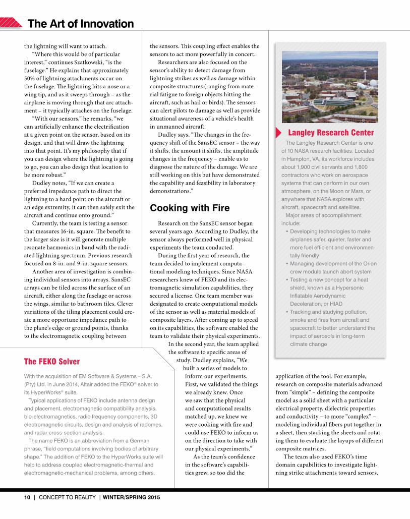
Langley Research CenterThe Langley Research Center is one
of 10 NASA research facilities. Located
in Hampton, VA, its workforce includes
about 1,900 civil servants and 1,800
contractors who work on aerospace
systems that can perform in our own
atmosphere, on the Moon or Mars, or
anywhere that NASA explores with
aircraft, spacecraft and satellites.
Major areas of accomplishment
include:
•Developing technologies to make
airplanes safer, quieter, faster and
more fuel efficient and environmen-
tally friendly
•Managing development of the Orion
crew module launch abort system
•Testing a new concept for a heat
shield, known as a Hypersonic
Inflatable Aerodynamic
Deceleration, or HIAD
•Tracking and studying pollution,
smoke and fires from aircraft and
spacecraft to better understand the
impact of aerosols in long-term
climate change

WInter/sPrIng 2015 | CONCEPT TO REALITy | 11
Dudley says, “With this software, we gained deep insights that we could not have acquired through physical experi-mentation alone.” He explains that the team would look at the surface cur-rents and electric field distributions on a sheet or sensor and review how they were emerging. From that, the team would tie electromagnetic first principles to what they were observing in the computational models back to the physical experiments.
“This led us to make incredible leaps in understanding how our sensor worked and interacted in a lightning environment or in a damage-detection application,” says Dudley.
“Once we would get a series of compu-tational models,” he continues, “we would conduct an experiment in the lightning lab or in our high intensity radiated fields’ chamber. For example, we would set up a shield-effectiveness experiment in which we would propagate a wave from one side of the sensor through a wall to the other side and characterize the amount of energy rejected due to the sensor, then compare it with the computational models.
“We would then build material mod-els, go to the shop, and lay up a particular weave or orientation of a composite mate-rial matrix. We would lay out a sensor array, strike it and observe the physical experiments. From that, we would analyze the data from the physical test, take that new knowledge, feed it back into FEKO and lead to improved designs.
“In this method of using the compu-tational electromagnetic modeling tool to inform our experiments, then feed experi-ments back into this computational model in an iterative approach, we achieved a sci-ence force multiplier for a small team of
five. We were able to pro-duce results more quickly and accurately than one would expect from a team of our size.”
To increase the effi-ciency and productivity of simulations, the team has upgraded to a 4-CPU license from a 1-CPU license. Previously, depending on the complex-ity of the model, analysis on a problem could take 24 hours. Now, with a par-allelized 4-CPU version of the software running on a faster PC cluster with multi-core capability, getting results can take as little as 30 minutes.
According to Dudley, the quick process-ing enables the team to explore even more complex models. It also opens the door to investigate the use of SansEC sensors on full-scale aircraft models.
Szatkowski envisions a “smart skin” concept using surface tiling arrays of SansEC sensors. The concept could be carried out in a couple of ways. The first approach is one in which the sen-sors would be interrogated for lightning strikes through antennas embedded on the composite, or by direct wiring to the sensors themselves. Instrumentation on board would quantify the health state of the aircraft.
The second approach would allow the interrogation system to be external to the aircraft. Ground inspection crews or maintenance personnel would conduct the structural health measurement post flight, enabling the SansEC sensors to assist in the visual inspections.
Modeling a full-scale composite aircraft is an extremely challenging prob-lem. According to Dudley, such a model would incor-porate realistic composite properties, including the electrical properties of the composites, which are vastly different from the highly conductive aluminum-skinned aircraft. Adding the
modeling of the SansEC sensors increases the computational complexity of the prob-lem. Having a comprehensive simulation tool like FEKO combined with powerful computer clusters, the research team hopes to one day overcome the challenge.
technology transfer While much of the SansEC sensor
research has been focused on lightning strike protection, damage detection and damage diagnosis of composite aircraft materials, the sensor technology has much broader applications.
Szatkowski explains that the SansEC resonance sensor can be used in various industrial and medical applications. For example, the automotive industry could use the sensors in tire applications to moni-tor for punctures, temperature, rotation rate or wear. In the food industry, sen-sors could detect spoiled products. In the oil and gas industry, they could be used to test for water levels, iron or salinity, block-ages, leaks or pipe integrity. In addition, the medical and biomedical segments could add SansEC sensors in bandages to monitor wounds. NASA is currently collaborating with industry on technology transfer.
According to the researchers, the uses for the SansEC sensors – and computa-tional modeling – are nearly limitless.
Beverly A. Beckert is Editorial Director of Concept
To Reality magazine.
For more information on FEKO, visit www.c2rmagazine.com/2015
Left: Image of an electric field map of a SansEC sensor. Right: Image of IR thermal data during lightning strike dis-playing the attachment (where lightning resided on the
sensor). This is a rough estimate showing correlation between the high electric field on the sensor to the lightning attachment location.

12 | CONCEPT TO REALITy | WInter/sPrIng 2015
Process automation
TThe Lockheed Martin Joint Strike Fighter (JSF) program aims to deliver affordable, next-generation striker aircraft weapon systems for the U.S. Navy, Air Force, Marines and allies. Currently, the program’s Lockheed Martin F-35 Lightning II aircraft are undergoing testing and final development.
There are three versions of the aircraft – one designed for conventional take-off and landing, one for short take-off/vertical land-ing and a carrier variant. These sophisticated aircraft feature an advanced airframe, auto-nomic logistics, avionics, propulsion systems, stealth and firepower.
Pilots assigned to fly such sophisticated aircraft are subject to high levels of accelera-tion – up to 9g – and must wear G-suits to prevent blackouts. In fact, pilots, depending on the mission, can potentially wear up to
nine layers of clothing.To prevent pilots suffering from heat
stress in the cockpit and on the ground, AMETEK Inc., a leading manufacturer of electronic instruments and electrome-chanical devices, was contracted to design a portable flight suit chiller unit. This cool-ing system works with a pilot cooling vest to maintain a pilot’s deep body core tempera-ture at ≤ 100.4° F (38° C).
Working under a tight schedule, the company leveraged VisSim™ solutions from Altair Inc. to design an embedded control system for the chiller unit. The VisSim plat-form enabled the team to build and simulate the plant model, design the entire controller and implement the controller design through rapid prototyping and debugging on the embedded target.
A model-based embedded development system enables AMETEK to design, simulate, create firmware for and validate a chiller unit control system.
chiller unit Keeps Joint strike Fighter Pilots cool
By Beverly A. Beckert
Pilot flight suit with AMETEK’s personal cooling unit (PCU) shown in the lower right.

WInter/sPrIng 2015 | CONCEPT TO REALITy | 13
a cool system
The chiller unit or personal cooling unit (PCU) forms part of the individual cooling equipment, or ICE. Four components com-prise the ICE system: a PCU, a Li-ion battery, a battery charger and the fluid charger.
AMETEK Principal Engineer Kevin Godfrey explains that the PCU interfaces with the cooling vest and delivers the cool-ing fluid. It uses a vapor cycle cooling circuit and receives fluid from the cooling vest, which transfers the heat load extracted from the pilot.
In the cockpit, the PCU is powered by the aircraft’s power supply; the Li-ion battery provides the power to the PCU for ground use and attaches to it for ease of carrying. The battery charger provides the charg-ing profile required by the battery assembly and ensures the correct phase of charging is implemented by monitoring the voltage and current draw taken by the Li-ion bat-tery’s cell pack. The fluid charger is designed to operate in a sheltered environment and has a manually operated pump that can fill, pressurize and drain both the PCU and the cooling vest.
According to Godfrey, the pilot’s vest circulates water glycol, and the chiller unit functions as a mini refrigeration system. “It modulates the temperature of the cool water glycol fluid through piping next to the pilot’s skin,” he says.
The chiller unit’s control system moni-tors the temperature sensors and motor speed feedback and controls the compressor, expansion valve, and fan pump, as well as regulating the temperature to the pilot. The temperature can vary between 57° F (14° C) to 72° F (22° C.)
Godfrey notes that the system has multi-ple control loops. One, for example, regulates the fluid-out temperature and the compres-sor speed to achieve a specific temperature setting. Another control loop monitors the temperature difference over the evaporator and controls the refrigerant flow.
Part of the design challenge is monitoring the various variables and developing the code that goes to the controlling device to make those adjustments automatically. The chiller unit must also run within its power limits to prevent damage.
model-Based design When project development of the chiller
unit began, Godfrey and his team had a good idea of what they wanted to develop in terms of hardware. The team decided to use a model-based design approach – leveraging simulation tools to create virtual prototypes and to check that the prototypes worked properly before committing to the design. Godfrey had used VisSim tools previously and believed that its model-based embed-ded development system, VisSim Embedded, would assist them in development efforts.
As part of the process, the team had to model the plant (the cooling vest and the portable chiller unit) as well as its operations and develop the control system that was to be embedded within the chiller unit.
VisSim Embedded enabled engineers to create a working model of the combined chiller unit and control system via a block diagram approach. They correlated and refined the plant model using measurements of plant responses in the lab. Engineers then built a multi-loop PID controller in VisSim with interlock safety stages that stepped through the start-up and shutdown actions necessary to avoid damage to sensitive device components. This implemented “model-in-the-loop,” or MIL, testing.
After engineers debugged and tuned the controller in offline VisSim simulations,
they automatically generated ANSI C code from the controller model, compiled and downloaded the code directly to the Texas Instruments (TI) C2000 target chip, using a bi-directional JTAG link (IEEE standard). Engineers tested the control algorithm firmware running on the C2000 by using the VisSim target interface block. It resides in the VisSim plant model running in real time on the PC and uses JTAG technology to easily provide an interface between virtual
AMETEK, Inc. is a global
manufacturer of electronic
instrument and electromechanical
devices. It has more than 120
manufacturing locations around the
world and generated $3.6 billion in
sales in 2013.
The company, with a dozen
divisions and business units, serves
the following markets:
•Aerospace and Defense
•Connectors, Metals and
Engineered System & Materials
•Electronic Instruments
•Motors and Blowers
•Power
a global reach

14 | CONCEPT TO REALITy | WInter/sPrIng 2015
Process automation
plant outputs supplied to the firmware and firm-ware control output supplied back to the virtual plant model in VisSim. This implemented “processor-in-the-loop,” or PIL, testing.
When engineers were satisfied with the embed-ded controller’s behavior, they replaced the interactive JTAG input/output (I/O) ports with VisSim blocks for analog-to-digital converter input, general-purpose I/O, pulse-width-modulated (PWM) outputs and custom hardware sensors. Engineers again generated ANSI C code from the controller model, downloaded it to the TI target and ran it against the model simulated in VisSim in real time. At this point in the development process, the controller was electrically connected to the VisSim virtual plant using VisSim/Real-Time PRO to interface to Measurement Computing PCI-based analog and digital I/O PC boards to create analog and digital I/O signals equivalent to the signals from the real plant. This implemented “hardware-in-the-loop,” or HIL, testing.
Once that verification level was complete, the con-troller firmware was run with the actual hardware plant. Each subsystem was vigorously tested employing this established design-simulate-validate procedure.
The testing was also key to adhering to the Safety Evidence Assurance Level (SEAL) standards required by Lockheed Martin. Bi-directional hyperlinks to requirements documents were placed in the VisSim diagram using hyperlink-enabled label blocks. VisSim compound block coloring was employed to track vali-dation progress.
VisSim data export with automatic source diagram and time stamp served as evidence of validation of implementation in meeting the SEAL requirements. VisSim Embedded helped engineers prove that the chiller unit achieved the compulsory safety integrity level through subsystem and whole system testing as well as test result archiving.
efficiency and QualityAccording to Godfrey, the team wanted to use a
turnkey package in the model-based design process. “We wanted to work in one environment, for the entire tool chain,” he says. AMETEK did not want to perform modeling work in one package and then turn it over to a separate coding team to write the C code and then verify it.
Godfrey says, “The VisSim auto code generator allowed me to develop the control algorithm against the model within a simulation environment on the PC – and then take that core control algorithm and put it down on the TI microcontroller unit (MCU) and control the refrigeration system.” He notes that
(Top) VisSim is a visual environment for modeling and simulating complex dynamic systems and for model-based development
of embedded systems. This image is an example of hardware-in-the-loop testing used in the development of a portable flight suit chiller unit. (Middle) The control plots from this VisSim analysis show heat load changes in the chiller unit.
In the AMETEK lab (right), Principal Engineer Kevin Godfrey used the VisSim environment to model the chiller unit before
committing to any hardware.

WInter/sPrIng 2015 | CONCEPT TO REALITy | 15
the C code generated from VisSim was con-cise, sharp and targeted.
In addition, VisSim supports a real-time operating system that responds to system events very quickly within the constraints of a control system running in real time. The Visual RTOS provides an “embedded expert,” of sorts, when it comes to generating C code for the TI DSP.
The TI target incorporates multiple I/O components on a single chip, reducing the size and cost of the final system while increasing its reliability. To develop the C code for each of the peripherals, however, is laborious, as a programmer would have to learn how all of the peripherals work and develop software for their respective applications.
VisSim provides the ability to code for all the peripherals, handling interrupts and scheduling tasks automatically, right from the graphical diagram.
With VisSim, AMETEK was able to iter-ate and optimize the code to be as efficient as possible. According to Godfrey, “It’s more critical within an embedded environment
with a small processor [to have efficiently generated code] because there are not a lot of extra processor resources. Otherwise, the code would be too big to fit in memory, and the system would run too slowly to control the equipment.”
Pleased PilotsTo date, Lockheed Martin has not started
formal inflight testing of the chiller unit, but it does have a unit that has undergone general pilot testing. According to Godfrey, the pilots are pleased with the chiller unit and don’t want to fly without it.
AMETEK was also pleased with its model-based development process and VisSim’s contribution to it. According to Godfrey, “One of the advantages of VisSim is that you are not directly coding in C. You are employing a diagram and using the automatic code generator to create the code.” He explains that if the automatically generated code proved too long, for exam-ple, he could go back and easily optimize it for efficiency.
“VisSim allowed us to model the system and be confident about our design before committing to any hardware,” says Godfrey. “The software guided us in the right path to take and sped up development.” When it came to the verification and validation exer-cises, the software allowed code segments to be individually tested and the results logged.
In addition, AMETEK worked closely with the VisSim consulting team, which pro-vided advice on making best use of VisSim to create TI MCU firmware, as well as fielding general support questions.
Moving forward, AMETEK plans to use the model-based development process on other projects. For example, it will lever-age its work in embedded processors on an armored fighting vehicle for Spain, an under-belly camera for a Turkish aircraft and a fan control for a Canadian vehicle.
Beverly A. Beckert is Editorial Director of Concept To
Reality magazine.
To learn more about VisSim, please visit www.c2rmagazine.com/2015
FLUIDON Gesellschaft für Fluidtechnik mbHJülicher Straße 338a - 52070 Aachen - Germany - www.fluidon.com
- Hydraulic and Pneumatic System Simulation
- Hydraulic and pneumatic simulation models for 1D standalone analysis and for co-simulation deployment
- Thermo-hydraulic, particle/filtration and pipeline dynamic simulation capabilities
- Support of FMI 1.0 co-simulation slave
®- Generic model export to Altair MotionSolve and ® ® to MATLAB /Simulink
- Open model source code and expandable model libraries
I
16 | CONCEPT TO REALITy | WInter/sPrIng 2015
trends in technology
In the late 1950s, engineers invented a method to study complex geometries undergoing loads. Eventually referred to as the finite-element method, it enabled users to model any geometry in any type of physical condition. Soon after its discovery, the first paper was pub-lished suggesting use of this method in an optimization loop to find an optimal, lightweight design.
Thirty years later, research efforts turned to using finite elements and optimi-zation techniques to find the best material distribution in a design space for a given load. At the University of Michigan, for example, professors and students imple-mented their findings into academic code that simulated bone growth trajectories. When one of the students joined Altair and brought news of this technology with him, Jim Scapa, founder and chief executive officer of Altair, saw the potential in engi-neering. Altair started collaborating with the University of Michigan and released the first commercial version of the software under the brand name OptiStruct® in 1993.
This theme of optimization – woven throughout the product development pro-cess – has been a constant for Altair since the introduction of OptiStruct. Over the years, the company has built upon a solid technological foundation to advance the capabilities of OptiStruct and expand it into a multi-physics solver platform.
early accoladesWhen OptiStruct was introduced, it
was enthusiastically received. In 1994, Altair received the coveted Industry Week “Technology of the Year” award for OptiStruct.
Early adopters included engineers in automotive companies like General Motors, Opel, Volkswagen and Audi. They recog-nized the potential of the technology for saving material in product development. By starting a design with a material layout that follows the load paths – and is, therefore, optimal – they were able to achieve material savings and reduce the number of design iterations downstream.
In 1996, Altair brought 100% of the development of OptiStruct in-house to
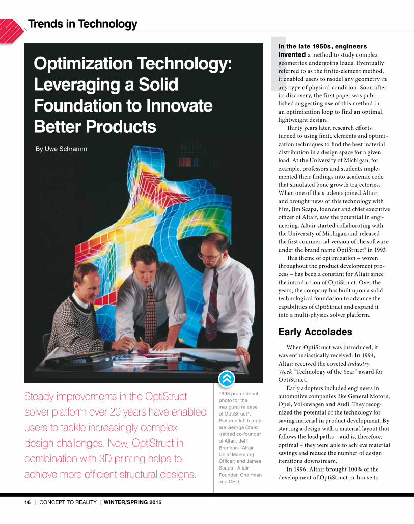
Steady improvements in the OptiStruct solver platform over 20 years have enabled users to tackle increasingly complex design challenges. Now, OptiStruct in combination with 3D printing helps to achieve more efficient structural designs.
optimization technology: leveraging a solid Foundation to Innovate Better Products
1993 promotional photo for the inaugural release of OptiStruct®. Pictured left to right are George Christ -retired co-founder of Altair; Jeff Brennan - Altair Chief Marketing Officer; and James Scapa - Altair Founder, Chairman and CEO.
By Uwe Schramm

WInter/sPrIng 2015 | CONCEPT TO REALITy | 17
Co
urte
sy o
f Vo
lksw
agen
AG
aggressively advance the technology and deeply integrate it with its growing suite of CAE offerings. Renowned optimization and software specialists Harold Thomas and Yaw-Kang Shyy joined the company. After only nine months, the first ver-sion of the new generation OptiStruct was released. One of the first projects included the design of an engine mount bracket from Volkswagen. The 23% weight reduc-tion was impressive.
As an early stage disruptive technology driven by growing industrial application, the development team worked hard on usabil-ity and functionality to fuel adoption and its value to the product development commu-nity. One area on which they concentrated was the need to consider manufacturing constraints right from the beginning. They introduced techniques such as filtering out small design features and considering draw directions for castings.
a new century, more Innovations
Though first adopted in the automotive industry, material layout via optimization techniques trickled into other industries. In 2000, aviation giant Airbus engaged with Altair to find the optimal material layout for the leading-edge wing ribs of its new superjumbo A380. Several hundred kilo-grams of material could be saved on a single plane. Soon after, Boeing also adopted the technology.
Since “structural optimization” as a discipline was still somewhat unknown and unfamiliar to engineers, Altair intro-duced a new service model called the Optimization Center. This model placed
consulting engineers from Altair ProductDesign together with client engineers to solve the toughest weight reduc-tion challenges posed in their product development process. In fact, Altair’s consulting arm was instrumental in driv-ing both the adoption of optimization technology and OptiStruct software development.
With wider adoption of OptiStruct technology, more requirements arose. For example, new physical phenomena needed to be introduced to the models in addition to static load path analysis. Further, more manufacturing techniques had to be considered during the conceptual stage of the design process in order to derive the right shape.
The need for more physics led to the implementation of such phenomena as structural stability, noise and vibration, temperature loading, impact loading, dynamics of mechanical systems, etc. Altair’s vision of simulation and optimization-driven design required that any new physics introduced into the solution also needed to be integrated with optimization. There is not simply a need for multi-physics simulation but rather for multi-physics-driven design and optimization.
As such, Altair embarked on a path to develop technology, including MotionSolve®, a multibody simulation code, as well as to acquire technology, such as RADIOSS®, a renowned crash simulation code. RADIOSS and MotionSolve have been integrated seamlessly and are used in unison with native OptiStruct solutions.
development trendsAdvances in manufacturing, including the introduction
of new materials and 3D printing, are currently the big-gest contextual drivers for the development of OptiStruct. Boeing’s 787 Dreamliner project has brought a lot of atten-tion to the effective use of composite materials in product development. The layout for such materials is not trivial. Exploiting the nearly unlimited flexibility of composites in design requires a simulation-driven process.
Composites allow structures that are completely cus-tomized to the respective loads. Only computer simulation and optimization can evaluate a large number of variants to arrive at the best possible solution. In this field, Altair engineers have designed an innovative new methodol-ogy for composite materials layout, and the approach has been well-suited to projects within the aerospace industry. In fact, the technology has won several awards for light-weighting innovation.
Recently, additive manufacturing, or 3D printing, has moved into the engineering mainstream. The biggest advantage of this approach to manufacturing is the near absence of design constraints. Additive manufacturing is very flexible and can actually produce the designs that are conceived via material layout optimization with little to no rework. Some processes even allow multiple materials in a single part. Other advantages include in situ manufactur-ing, reduction of lead time and removal of most logistics cost. This technology is tremendously promising and is the perfect manufacturing complement to OptiStruct to achieve the most efficient structural designs.
OptiStruct used to optimize the design of parts like the leading-
edge wing rib package shown above can result in as much as 40% mass reduction and a weight saving of over 500 Kg per aircraft.
Traditional Design
So
urce: Airb
us/B
AE
System
s
Cur
rent
Pr
oduc
tion
Bra
cket
Des
ign
Spac
e
Topo
logy
Opt
imiz
atio
n
Opt
imiz
ed
Prod
uctio
n B
rack
et
FEA
Verifi
catio
n
FEA
Mod
el
Design Process Using OptiStruct

18 | CONCEPT TO REALITy | WInter/sPrIng 2015
trends in technology
Altair’s understanding of the relation-ship between simulation and optimization is a big differentiator for the company. Physics may be complex, and brining rele-vant simulation into the design requires the use of optimization throughout the process.
Moving forward, Altair will continue to build on its solid foundation of optimi-zation tools. There are other domain areas that are unfamiliar with this message of optimization. Altair looks forward to the opportunity of expanding knowledge and providing the tools that enable users to innovate better products.
Uwe Schramm is Altair Chief Technical Officer,
Solvers and Optimization.
a Broad Platform
Aside from the capabilities of OptiStruct as a concept development tool, its platform enables a multitude of physics to be solved in parallel, coupled, or sequentially. Through the integration of new solvers, numerical procedures and material models, OptiStruct has matured into a multi-physics solver platform addressing complex loading environments. New optimization methods have been integrated, and the development team has consistently tar-geted ease of use, helping users choose the appropriate solution approach.
It is important to simulate multi-physics and to make models that represent real physics correctly. However, simulation results only describe a state. Of course, evaluating a number of parameters through multiple simulations helps comprehension of their influences. The ques-tion remains: What next?
Knowing the sensitivity of a response with respect to a design parameter does enable insights on how to change the parameters. Thinking about it will only yield the right answer occasionally, whereas optimization algorithms automatically trade different attributes towards the given requirement, yielding the right answer with a higher degree of certainty. Altair multi-physics uses optimization to leverage and trade differ-ent simulations of different disciplines to achieve design goals.
strategic designA conceptual tool like OptiStruct, used early in the design pro-
cess, enables strategic design – knowing where the load paths are, where to add or remove material, or where and how to modify a shape based upon materials considerations – which can improve design outcome. Given that OptiStruct is complex finite-element software, designers may not be willing to invest the time to ascend a rather steep learning curve.
With that in mind, Altair has developed solidThinking Inspire®, a conceptual design tool that incorporates material layout via optimization into an intuitive interface. This software has intro-duced a new mode of user interaction, whereby designers interact with and develop virtual prototypes based on optimized geometry. Details of the computational setup are hidden.
Design andoptimization ofcomposite floats.
Co
urte
sy o
f EA
DS
3D printed optimized aircraft door hinge bracket using the optimization engine available in OptiStruct and solidThinking Inspire.
Structural form-finding and multidisciplinary optimization with OptiStruct allow architects to explore and experiment with new shapes and new materials to build complex, innovative building structures.
For more information on OptiStruct and solidThinking Inspire, visit www.c2rmagazine.com/2015.

WInter/sPrIng 2015 | CONCEPT TO REALITy | 19
Altair’s PBS Works™ suite has been recognized as “Best HPC Software or Technology” in the
annual HPCwire Readers’ Choice Awards, presented at the 2014 International Conference for High
Performance Computing, Networking, Storage and Analysis (SC14), in New Orleans.
The coveted annual HPCwire Readers’ and Editors’ Choice Awards are determined through a
nomination and voting process with the global HPCwire community, along with a selection
process in which the editors of HPCwire make selections. The awards are an annual feature of the
publication and constitute prestigious recognition from the HPC community.
For more information, visit www.c2rmagazine/news/2015/PBS
altair PBs Works named “Best HPc software or technology”
altair acquires visual solutions Inc., adds vissim to HyperWorks Altair completed its acquisition of Visual Solutions Inc. in August 2014. The addition of VisSim™, an innovative visual language for mathematical modeling, simulation and model-based embedded system development, brings expertise in embedded controls to Altair’s HyperWorks® portfolio.
For more information, visit www.c2rmagazine.com/news/2015/VisSim
In the news
ruag space and altair design and optimize 3d Printed satellite antennae RUAG Space, Europe’s leading equipment supplier to the space industry, with the support of Altair ProductDesign, has used topology optimization in conjunction with additive manufacturing, or 3D printing, to redesign an antenna support for an Earth observation satellite.
Engineers used OptiStruct®, a multi-physics optimization solver in Altair’s HyperWorks® CAE suite, to create a stiffer yet lighter aluminum component. For design, they leveraged solidThinking Evolve®, Altair’s concept design and rendering technology.
Design freeze was reached after only four weeks. The component was then manufactured with a 3D printer from EOS, the German market leader in the area of industrial 3D printing.
For more information, visit www.c2rmagazine.com/news/2015/Ruag
Luxury Mobile Phone Manufacturer Dials Up the Altair Private Cloud Solution Vertu, the world-renowned English
luxury mobile phone manufacturer,
has invested in and deployed Altair’s
new HyperWorks Unlimited™ (HWUL)
private cloud solution for computer-
aided engineering (CAE). Fully
configured with high-performance
computing (HPC) hardware and
software, the solution offers unlimited
use of all Altair HyperWorks engineer-
ing applications.
Vertu has developed and deployed
an automated drop test simulation
process that is fully integrated into the
HWUL solution. From a CAD model, a
very high-fidelity drop impact FEA
model of the phone is set up to test
different drop orientations, velocities
and other scenarios selected by the
user. The specified set of impact
events are then scheduled and solved
in parallel across the HWUL appliance
using Altair’s RADIOSS® structural
analysis solver for highly non-linear,
dynamic problems.
For more information, visit www.c2rmagazine.com/news/2015/Vertu
20 | CONCEPT TO REALITy | WInter/sPrIng 2015
In the news
Jaguar Land Rover won the 2014 Altair Enlighten Award competition
for the development and implementa-
tion of its premium lightweight
architecture design concept on the
latest Range Rover vehicles. The
award, presented in collaboration
with the Center for Automotive
Research (CAR), is the automotive
industry’s first award program created
specifically to acknowledge innova-
tions in vehicle lightweighting.
Its lightweight vehicle process takes
a holistic approach to CO2 reduction,
linking strategies of weight reduction
in the body and chassis systems to
powertrain and related secondary
weight savings – while also maximiz-
ing recycled material use and lowering
energy consumption during the
manufacturing stage. The overall
result is a significant decrease in the
carbon footprint of the vehicle, verified
through lifecycle analysis tools.
For more information, visit www.c2rmagazine/news/2015/JaguarLandRover
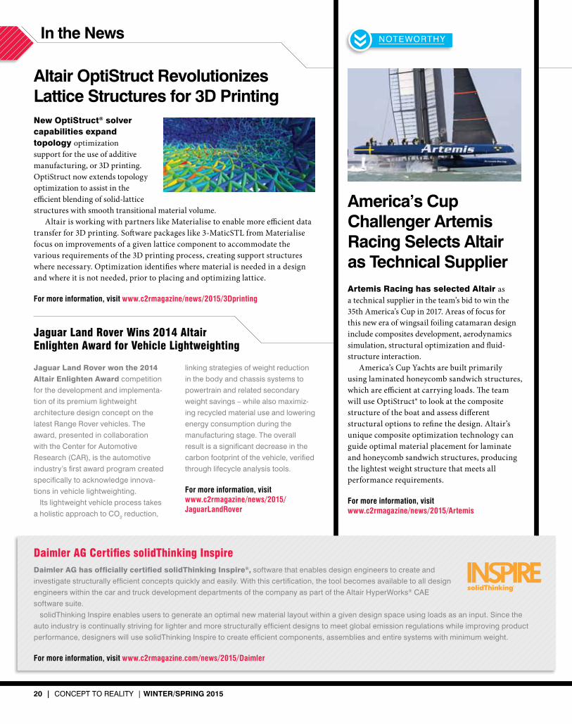
america’s cup challenger artemis racing selects altair as technical supplier Artemis Racing has selected Altair as a technical supplier in the team’s bid to win the 35th America’s Cup in 2017. Areas of focus for this new era of wingsail foiling catamaran design include composites development, aerodynamics simulation, structural optimization and fluid-structure interaction.
America’s Cup Yachts are built primarily using laminated honeycomb sandwich structures, which are efficient at carrying loads. The team will use OptiStruct® to look at the composite structure of the boat and assess different structural options to refine the design. Altair’s unique composite optimization technology can guide optimal material placement for laminate and honeycomb sandwich structures, producing the lightest weight structure that meets all performance requirements.
For more information, visit www.c2rmagazine/news/2015/Artemis
Daimler AG Certifies solidThinking InspireDaimler AG has officially certified solidThinking Inspire®, software that enables design engineers to create and
investigate structurally efficient concepts quickly and easily. With this certification, the tool becomes available to all design
engineers within the car and truck development departments of the company as part of the Altair HyperWorks® CAE
software suite.
solidThinking Inspire enables users to generate an optimal new material layout within a given design space using loads as an input. Since the
auto industry is continually striving for lighter and more structurally efficient designs to meet global emission regulations while improving product
performance, designers will use solidThinking Inspire to create efficient components, assemblies and entire systems with minimum weight.
For more information, visit www.c2rmagazine.com/news/2015/Daimler
NOTEWORTHy
altair optistruct revolutionizes lattice structures for 3d PrintingNew OptiStruct® solver capabilities expand topology optimization support for the use of additive manufacturing, or 3D printing. OptiStruct now extends topology optimization to assist in the efficient blending of solid-lattice structures with smooth transitional material volume.
Altair is working with partners like Materialise to enable more efficient data transfer for 3D printing. Software packages like 3-MaticSTL from Materialise focus on improvements of a given lattice component to accommodate the various requirements of the 3D printing process, creating support structures where necessary. Optimization identifies where material is needed in a design and where it is not needed, prior to placing and optimizing lattice.
For more information, visit www.c2rmagazine/news/2015/3Dprinting
Jaguar Land Rover Wins 2014 Altair Enlighten Award for Vehicle Lightweighting

C
M
Y
CM
MY
CY
CMY
K

The Altair Enlighten Award is presented in collaboration with the Center for Automotive Research (CAR), and recognizes achievements in weight reduction across the automotive industry from motorcycles to passenger cars, light-trucks to commercial vehicles and buses. Now in its third year, the 2015 award will be presented at the 50th annual CAR Management Briefing Seminars in Traverse City, Mich., August 3-6, 2015.
Automotive’s Only Award Dedicated to Vehicle Lightweighting
Find out more, see the past winners and submit your entry at altairenlighten.com/award
The objectives of the Altair Enlighten Award are to:
• Honor the greatest achievements in weight saving• Inspire interest from policymakers, educators, students and the general public in the
environmental impact, technical depth and diversity of weight saving innovations• Create further competition for new ideas within industry• Provide an incentive to share technological advances
2013 WINNER: BASF 2014 WINNER: JAGUAR LAND ROVER


![The Error is the Feature: How to Forecast Lightning using ...and CellMOS [14] try to detect thunderstorm cells and predict their movement. Lightning detection systems such as LINET](https://img.pdfslide.us/doc/110x75/5ecad127598f8628467420dc/the-error-is-the-feature-how-to-forecast-lightning-using-and-cellmos-14-try.jpg)