Embed Size (px)
Citation preview

NASA-CR-174647
N/ ANational Aeronautics andSpace Administration
R84AEB380
P_Cr_p')c_I
EXTENDED PARAMETRIC REPRESENTATION OFCOMPRESSOR FANS AND TURBINES
Volume !!1 - MODFAN User's Manual
FINAL REPORT
March 1984
By
General Electric Company
Aircraft Engine Business Group
Advanced Technology Programs Dept.Cincinnati, Ohio 45215
FOR
NATIONAL AERONAUTICS AND SPACE ADMINISTRATIONLEWIS RESEARCH CENTER21000 BROOKPARK ROAD
CLEVELAND, O_135
Ul
Oo
ContractNA$3-23055
SEliEIIAL 0 ELECTRICAircraft Engine Business Group
Advanced Technology Programs DepartmentCincinnati, Ohio 4621S
r--
https://ntrs.nasa.gov/search.jsp?R=19860014467 2018-06-30T00:21:26+00:00Z


1 RepOrt No 2 Government Accession No 3 Rec_p,ents Catalog %o
NASA CR-174647
4 T,tle ano SoDa,tie
Extended Parametric ReDreseptation of Compressor Fansand Turbines Vol. Ill - MhDF#N UFER'S Manual (Parametric Modulating
Flow Fan)
7 Author{s;
G.L, Converse
g Performing Organization Name and Addre_
General Electric CompanyAircraft Enaine Business GroupCincinnati, Ohio 45215
12 Sponsoring Agency Name and Address
National Aeronautics and Space AdministrationWashinnton, D.C. 20546
5, Report Date
March 1984
6 Performing Orgamzahon Co0e
8. Performing Organization Report _o
R84_AEB380
10 Work Unit No
11 Contract or Grant No
NAS3-23055
13, Type of Report and Period Covered
Contract ReportAugust 1982 - October 1983
14 Sponsoring Agency Code
15 Supplementary Notes
Project Mananer, James W. Gauntner, Aerospace Engineer, NASA
Lewis Research Center, Cleveland, Ohio
16 Abstract
A modeling technique for single stage flow modulating fans or centrifugal compressors has beendevelooed which will enable the user to obtain consistend and rapid off-desian performance fromdesiQn point input. The fan flow modulation may be obtained by either a VIGV (variable inlet auidevane) or a VPF (variable pitch rotor) option, Only the VIGV option is available for the centrifugalcompressor. The modelinn technique has been incorporated into a time-sharinm proaram to facilitateits use, Because this report contains a description of the input output data, values of typicalinputs, and example cases, it is suitable as a user's manual. This report is the last of a three
volume set describina the parametric representation of compressor fans, and turbines. The titlesof the three volumes are given below:
(I) Volume I CMGEN USER'S Manual (Parametric Compressor Generator)(2) Volume II PART USER's Manual (Parametric Turbine)(3) Volume I]I MODFAN USER's Manual (Parametric Modulating Flow Fan)
17. Key Words (Suggested by Author(s))
Parametric Fans
Parametric Centrifugal CompressorsOff-Desion PerformanceFlow Modulation
19 S_ur,tv Cla_if. (of this report)
Unclassi.fied
18 Distribution Statement
20. Security Classif. (of this page) 21_ No. of Pages
Unclassified 50
22 Pr,ce"
NASA-C-168 (Rev I0-75)


TABLE OF CONTENTS
Page
1.0 INTRODUCTION
2.0 PROGRAM STRUCTURE
3.0 PROGRAM INPUTS 5
4.0 PROGRAM OUTPUTS 9
5.0 PROGRAM DIAGNOSTICS i0
6.0 EXAMPLE CASES 12
7.0 ANALYTICAL BACKGROUND
7.1 Method of Map Generation
7.2 Discussion of Variable Geometry Options for
Axial Flow Fans
7.2.1 Variable Inlet Guide Vane (VIGV) Option
7.2.2 Variable Pitch Rotor (VPF) Option
7.3 Discussion of Centrifugal Compressor Option
7.3.1 Fixed Geometry Centrifugal Compressors
7.3.2 Variable Inlet Guide Vanes (VIGV)
23
23
24
24
27
37
37
37
REFERENCES 46
lq{ECEDING PAGE ,BLANK NOT FILblED
iii


LIST OF FIGURES
FIGURE NO.
i,
2.
3.
4.
5.
6.
7.
8.
9.
I0.
ii.
12.
13.
14.
15.
16.
17.
18.
19.
20.
21.
DESCRIPTION PAGE
Flow Chart Showing Flow of Control in MODFAN 4
MODFAN Sample Terminal Conversation 6
Parametric Fan Performance Map (PR=I.6) 8
Vector Diagram for Variable Inlet Guide Vanes (VIGV) 25
Stage Characteristics for VIGV Axial-Flow Fan 26
Parametric VIGV Axial Flow Fan (STPI=- i0.0 °) 28
Parametric VIGV Axial Flow Fan (STPI=0.0 °) 29
Parametric VIGV Axial Flow Fan (STPI=+20.0 °) 30
Parametric VIGV Axial Flow Fan (STPI=+40.0 °) 31
Flow Variation Along Min-Loss Locus 32
(Single Stage VIGV Fan)
Pressure Rise Variation Along Min-Loss Locus 33
(Single Stage VIGV Fan)
Efficiency Variation Along Min-Loss Locus 34
(Single Stage VIGV Fan)
Vector Diagram for Variable Pitch Rotor (VPF) 35
Stage Characteristics for VPF 36
Flow Variation Along Min-Loss Line (Centrifugal Compressor) 38
Pressure Rise Variation Along Min-Loss Locus 39
(Centrifugal Compressor)
Efficiency Variation Along Min-Loss Locus 40
(Centrifugal Compressor)
Stage Characteristic for VIGV (Centrifugal Compressor) 42
Flow Variation Along Min-Loss Locus 43
(VIGV Centrifugal Compressor - Impeller Only)
Pressure Rise Variation Along Min-Loss Locus 44
(VIGV Centrifugal Compressor - Impeller Only)
Efficiency Variation Along Min-Loss Line 45
(VIGV Centrifugal Compressor - Impeller Only)


1.0 INTRODUCTION
The NASA Lewis Research Center employs a general computer program NNEP (Ref.l)
for calculating the thermodynamic performance of jet propulsion engines. To calculate
off-design engine performance, the _EP user must input component maps defining the
characteristics of the various components over their full range of operating con-
ditions.
For early cycle analysis of advanced propulsion systems, these map characteris-
tics are not generally known because the geometry of the component has not been
specified. Furthermore, the typical user of NNEP is not sufficiently knowledge-
able and/or cannot afford the time to do an extensive design followed by an off-design
analysis of the component in question to define the map characteristics. Typically,
in this early stage, the user scales some available map.
The available methods for scaling maps can lead to significant errors in com-
ponent representations. A traditional method of scaling a compressor map retains the
flow speed relation of the base map and applies a constant pressure rise scalar cal-
culated at the design point. Size scaling is, of course, legitimate. The accuracy of
such a procedure can be considerably improved by using parametrically generated com-
ponent maps. A parametric component representation can be thought of as a scaling pro-
cedure which uses the key design point parameters to impact the fundamental differences
in the map characteristics when generating the component maps.
The objective of the present study is an improved method of representing single
stage flow modulating fans and/or compressors of either the axial or centrifugal types
when performing calculations of off-design performance for advanced air-breathing jet
engines. The axial flow machines include flow modulation through either variable inlet
guide vanes (VIGV) or variable rotor pitch (VPF). The centrifugal compressors include
only the variable inlet guide vane (VIGV) option. This method, which is a computer pro-
gram called MODFAN (i.e., flow modulating fan) is compatible in both form and format
with the cycle program of Reference 1 and the example map representation of Reference
2.
This report is a user's manual for the computer program MODFAN and contains a
description of the input-output data, values of typicel inputs, and sample cases. A
brief description of the engineering analysis used to generate a program is given near
the end of the report, i
The program uses design point data and semi-empirical correlations to
generate off-design values of corrected flow,efficiency, and pressure ratio over a
range of blade angles, corrected speeds, and pressure ratio parameters specified
by the user.

2.0 PROGRAM STRUCTURE
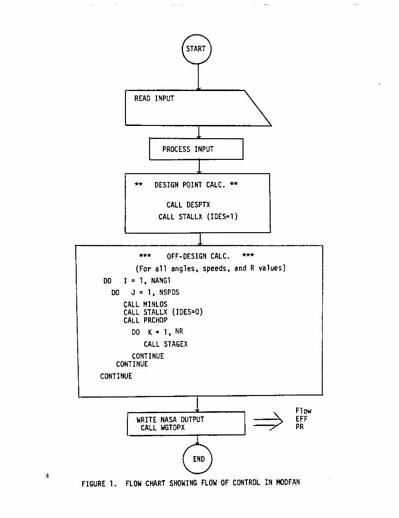
A flow chart showing the flow of control in the MODFAN program is shown in
Figure I. The program first displays a description of the design point variables
together with the default values. The user can then change the default values as
desired. The input is then checked and the updated input displayed. This completes
the input phase of the program. The design point calculations are then carried out.
These calculations determine the blade row overall geometries from the design
point input.
Once the design point calculations have been completed, the off-design calcula-
tion can begin. The calculations for each of the desired angles, speeds, and *R values
are carried out in a set of nested DO loops. For each angle and speed, the min-loss
point (i.e., the map backbone) is first located. Then the values of work coefficient
both at stall and at a pressure ratio of unity are determined. These values of work
coefficient form the upper and lower limits of the speed line. The R values are then
converted into equivalent work coefficient values, and the fan characteristics
determined. When the inner or R DO loop is completed the speed is incremented and the
calculation repeated_ when all speeds are completed, the angle is incremented.
After the off-design calculation has been completed, MODFAN writes the three
data sets required for the computer program NNEP input.
*R is a measure of the relative distance along a speed line starting from R=I at
stall.
READ INPUT
PROCESS INPUT I
** DESIGN POINT CALC. **
CALL DESPTX
CALL STALLX (IDES=I)
*** OFF-DESIGN CALC. ***
(For all angles, speeds, and R values)
DO I = l, NANGI
DO J = l, NSPDS
CALL MINLOS
CALL STALLX (IDES=O)CALL PRCHOP
DO K = l, NR
CALL STAGEX
CONTINUE
CONTINUE
CONTINUE
I NAsAOUTPUTCALL WGTOPX /-
Flow
EFF
PR
FIGURE I. FLOW CHART SHOWING FLOW OF CONTROL IN MODFAN

3.0 PROGRAM INPUTS
Most of the MODFAN inputs are of the free-field format (NAMELIST) type, and
begin in column two. The only exception is the initial type switch which requires
either a 1 or 0 as a response. The program first gives a brief description of the
variables used in the NAMELIST INPUT. The default settings of these variables are
then displayed. The user can then enter changes in the design point values and/or
the range of angle settings, speeds, and R values desired. If the user wishes the
program to generate a value for the design point efficiency, a zero value should be
input for EFFD. The program will then echo the updated NAMELIST and go into exe-
cution. Upon completion, the program will display a message to the effect that the
NASA output files have been written on file codes 30, 31, and 32.
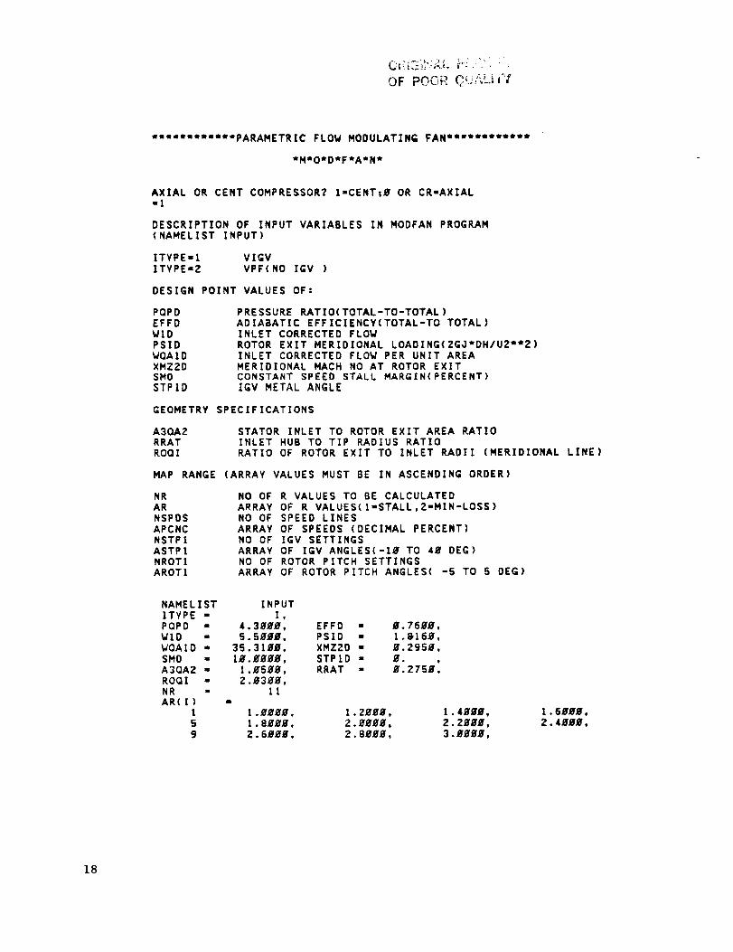
A sample of this showing the terminal conversation is shown in Figure 2 .
This example is for a axial flow fan having fixed geometry. Note that all of the
design point values have been reset as well as the range of inlet guide vane angles
and corrected speeds. The range of R values has not been altered. The R values are
used to fix a point on a speed line. The R value is unity at the stall line and in-
creases along a constant speed line as the flow increases. The algorithm used in
MODFAN forces a value of R equal to two at the min-loss point which is slightly
below the peak efficiency on the speed line. The concept of min-loss is discussed
in detail in Reference 3 .
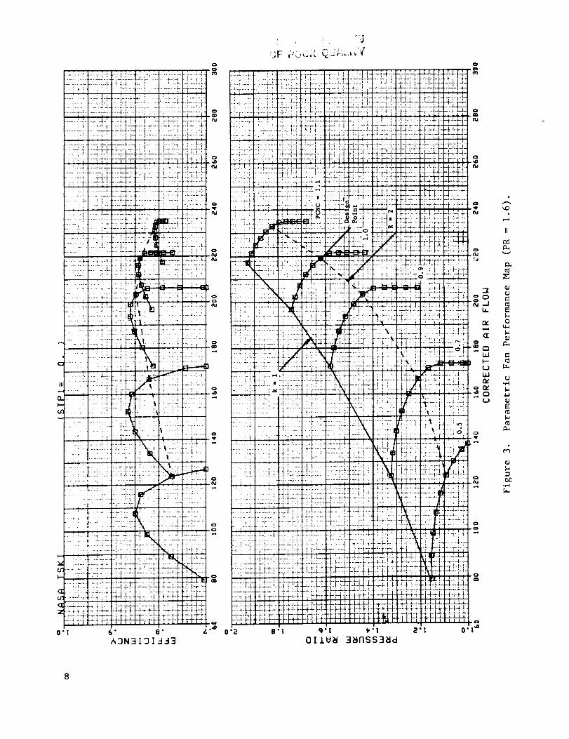
The fan map generated by the program from the input values given in Figure 2
is shown in Figure 3. The locus of the R=I and R=2 lines have been indicated on
the figure.

OF PO(_FC -,_r"_i_,_.,_,++_i_ +:
"*'''''*tet'PARAMETRIC FLOW MODULATING FAN **+'*'**eem_
eM'O_D*F*AtNn
AXIAL OR CENT COMPRESSOR? I-CENT;B OR CR-AXIAL-J
DESCRIPTION OF INPUT VARIABLES IN MODFAN PROGRAM(NAMELIST INPUT)
ITYPE-1 VIGVITYPE-2 VPF(NO IGV )
DESIGN POINT VALUES OF:
POPD PRESSURE RATIO(TOTAL-TO-TOTAL)EFFD ADIABATIC EFFICIENCY(TOTAL-TO TOTAL)W1D INLET CORRECTED FLOWPSID ROTOR EXIT MERIDIONAL LOADING(ZGOtDH/U2-12)WQA1D INLET CORRECTED FLOW PER UNIT AREAXMZ2D MERIDIONAL MACH NO AT ROTOR EXITSMD CONSTANT SPEED STALL MARGIN(PERCENT)STPID IGV METAL ANGLE
GEOMETRY SPECIFICATIONS
A3QAZ STATOR INLET TO ROTOR EXIT AREA PATIORRAT INLET HUB TO TIP RADIUS RATIOROOI RATIO OF ROTOR EXIT TO INLET RADII (MERIDIONAL LINE)
MAP RANGE (ARRAY VALUES MUST BE IN ASCENDING ORDER)
NRARNSPDSAPCNCNSTP1ASTPINROT1AROT1
NO OF R VALUES TO BE CALCULATEDARRAY OF R VALUES(I=STALL,Z=MIN-LOSS)NO OF SPEED LINESARRAY OF SPEEDS (DECIMAL PERCENT)NO OF IGV SETTINGSARRAY OF IGV ANGLES(-Ig TO 4m DEG)NO OF ROTOR PITCH SETTINGSARRAY OF ROTOR PITCH ANGLES( -5 TO 5 DEG)
NAMELIST INPUTITYPE = I,PQPD - 1.655g,WID = ZZ3.8_#_,WQAID = 41,_7_,SMD " I4.I_g_,A3QA2 - g.96#g,ROQI = l._Bgg,NR - IIAR(1)
I I.gggB,5 1.8_g_,9 Z.6_gg,
EFFD - B.B34B.PSID - _.8ZZ6,XMZZD - B.45BB,STPtD - g.
!
RRAT - g.5_g_,
2.ggBg, 2.2ggg,2.8g_g, 3.gBBB,
Figure 2. MODFAN Sample Terminal Conversation.
6

OR|GIN.,_.L p,.:l.:,, r!
OF pOOR C ',?i't_'/_"
NSPDS = 6APCNC{I) =
1 B.Sg_B,5 1._9B,
NSTPI - 3ASTPI(I) -
! B. oNROTI - gAROTI(I) =
1 B.END NAMELIST
ENTER CHANGES TO
_.7ggg, B.8H_,l.l_,
2_.gg_m, 4w._gBB,
INPUT
NAHELIST INPUT=$INPUT NSTPI/ASTPI=9.H,-PQPD=l.62,EFFD=.84,VQAID=4g.g.V1D=219.2,PSID=.863,=XMZ2D=.S,SHD=Z_.g. STPID=B.g,A3QAZ=I.B5,RRAT=.5,ROQI=I.B,=NSPDS/APCNC=.5,.7,.9,1.H,I.I,=$
B.9gBB,
INPUTI,
1.629g,219.zggg,
4g.gggg,2g.ggg_,
l.g5gg,
11m
1._g,1.S_gg,Z.6ggg,
5
1.1ggg,1
NAHELIST[TYPE =PQPD =WID =WGA1D =SHD =A3QA2 =ROQI =NRAR(I)
I5g
NSPDS -APCNC([) =
!5
NSTP! -ASTPI(I) •
INROT[ =AROTI(1) -
I g.END NAMELIST INPUT
OUTPUT ON IFC=3g,31,3Z
EFFD = W.84gB,PSID • B.B63g,XMZZD = g.5ggB,STPID = g.RRAT = _.5ggg,
1.2ggH, 1.4ggg, 1.6gHg,2.gggg, 2.2ggg, Z.4Hgg,2.8g_g. 3.g_,
PROGRAM COMPLETE &
Figure 2. MODFAN Sample Terminal Conversation (Continued).
0 °
L,_•i.;d- N=.-;d--. ' '_u =--!--,--_b-•- _--!-. I d-d •
-_..f.,ff.-!-i.-.:-_.7•
'--!7 ? I"--K "_+_
r ":' -i _ I- '--'-!'7-" :
I-f ._!_.!._•.:.t"I:.................... a_.L
::::.7:£:[ :_-T2!-: :!:;i::i 7- I i-T#-: 7-I-i
_-;- .--7 f--_-;-!....... "+| "T'T" i'- ---.-i-+.
ii;i T.r -P!-........._!z_...... t 7 ............. i----P-
:2:_- -" :T;: ''
' t!il,i_i 4;I
i ..... .L.... -!-. t-!.• _-; t .... !..........!•i i
. !: I=:'LI. '
•:: : !: :i: 7i:711%_ ..i !i'-I .... l ....... ! i-
i:i tiliiii""
..... i ,i:-]i _
.... ,-r -_ .....
............. I.
...... ! - .... [
'i L-,2 : _..,...
..... _ 7........
' I I t L:.-_.i : _L:4.
: : " :: i: ........LLLb-i. i •....... _ _- ...., .-._-.
i-£ .... :,-+.i...:i::: :;i ::2::::::: + L-_.+._ ,.+ _,-;. _ .+-!_ ! I , i i
,-÷ _+-! !--_-*.-Nd:-.
6"_3N3
:::"'::', I :.::::: ]

4 •0 PROGRAM OUTPUTS
The basic output from the program consists of three tables. These tables
show the variation in corrected flow, efficiency, and pressure ratio for each of
the vane or rotor angles, R-values, and corrected speeds specified in the input.
The output tables for the default cases are shown on pages 15 thru 17 and 20 thru
22. The table structure is compatible with NASA cycle deck requirements given in
Reference 2 (pages 23 and 24).
The output tables can be visualized as three dimensional, composed of a
series of planes with each plane assigned a value of angle position, STPI or ROTI.
Then in each angle plane, the dependent variable (ordinate axis) is a function of
corrected speed, SPED, and R value. The dependent variables are respectively
corrected flow, total-to-total efficiency, and pressure ratio.
For example, in the output table on page 20 the 12 lines of the dependent
variable correspond to the 6 values of corrected speed, two lines per speed. Within
each speed there are ii R values.
It should be noted that for pressure ratios less than unity the efficiency is
negative. These efficiency values are not fncorrect, however, the efficiency be-
havior in this region makes curve fitting and interpolation of efficiency values
extremely difficult. For this reason many engine manufactures use some form of locus
or temperature ratio parameter rather than efficiency for interpolation. The solution
used here was to simply discard the information below unity pressure ratio and to
display the solution for unity pressure ratio for all values of R at which the
pressure ratio is less than unity. This means that identical values of pressure ratio
(PR=I.0), flow and efficiency (EFF=O.0) will appear in the output table on any speed
line where the value of R results in a pressure ratio less than unity.
9

5.0 PROGRAM DIAGNOSTICS
The MODF_N computer program contains error printouts to aid the user in
trouble shooting. A list of the error messages and their meaning are given
below.
ERROR IN SUBROUTINE MINLOS.
PCN = F7.3, STPI = F7.3, ROTI = F7.3, ERR = F7.4
Failure to find the mln-loss or "backbone location"
at the input corrected speed and angle. The rotor
is not choked.
ERROR IN SUBROUTINE ROTORC
TANAI = F7.3, PCN = F7.3, PSI2J = F7.3, ERR = F7.4
Failure in the Newton-Raphson loop which solve the
continuity equation across the rotor for the case
where the rotor is choked.
NO STALL INTERSECTION FOUhU): PCN = F7.2
Failure in the STALLX Subroutine. No stall intersection
found at the specified speed and 4>2.
i0
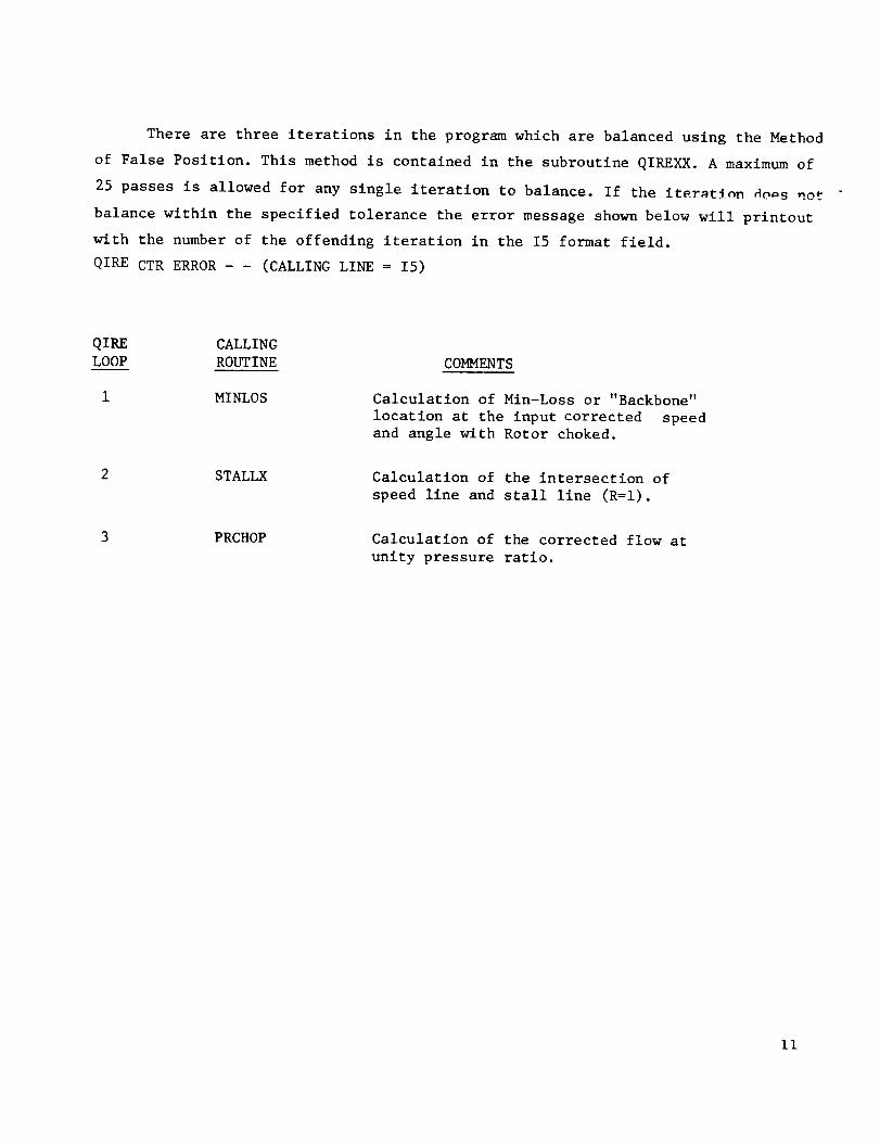
There are three iterations in the program which are balanced using the Method
of False Position. This method is contained in the subroutine QIREXX.A maximumof
25 passes is allowed for any single iteration to balance. If the It_r_t_n_ 4o=s not -
balance within the specified tolerance the error messageshownbelow will printoutwith the number of the offending iteration in the I5 format field.QIRECTRERROR- - (CALLINGLINE = I5)
QIRE CALLINGLOOP ROUTINE COMMENTS
I MINLOS
2 STALLX
3 PRCHOP
Calculation of Min-Loss or "Backbone"
location at the input corrected speed
and angle with Rotor choked.
Calculation of the intersection of
speed line and stall line (R=I).
Calculation of the corrected flow at
unity pressure ratio.
Ii

6.0 EXAMPLE CASES
Two example cases are given in order to illustrate the use of the program.
The first case utilizes the default settings to generate a single stage fan having
variable inlet guide vanes (VIGV). The second case uses the default settings to
generate a single stage fixed geometry centrifugal compressor.
A complete record of the two terminal sessions including a listing of the
output tables is given on the following pages. The program inputs and outputs have
been discussed previously in Sections 3.0 and 4.0.
12

(_, L, ,-':_-;' 7 ..
OF FOg;P, QU_,LI'_"_'
*Q***_t_t_*PARAMETRIC FLOW MODULATING FAN *nmf****'°*tt
_M*O*D*F*A'N*
AXIAL OR CENT COMPRESSOR? 1-CENT;B OR CR-AXIAL
DESCRIPTION OF INPUT VARIABLES IN MOOFAN PROGRAM(NAMELIST INPUT)
ITYPE-1 VIGVITVPE-2 VPF(NO IGV )
DESIGN POINT VALUES OF:
PQPDEFFDWIDPSIDWQA1DXMZ2DSMOSTPID
PRESSURE RATIO(TOTAL-TO-TOTAL)ADIABATIC EFFICIENCY(TOTAL-TO TOTAL)INLET CORRECTED FLOWROTOR EXIT MERIDIONAL LOADING(2GJ'DH/UZ'*Z)INLET CORRECTED FLOW PER UNIT AREAMERIDIONAL MACH NO AT ROTOR EXITCONSTANT SPEED STALL MARGIN(PERCENT)IGV HETAL ANGLE
GEOMETRY SPECIFICATIONS
A3QAZRRATROQI
STATOR INLET TO ROTOR EXIT AREA RATIOINLET HUB TO TIP RADIUS RATIORATIO OF ROTOR EXIT TO INLET RADII (MERIDIONAL LINE)
MAP RANGE (ARRAY VALUES MUST BE IN ASCENDING ORDER)
NRARNSPDSAPCNCNSTPIASfPI
NROTIAROT1
NO OF R VALUES TO BE CALCULATEDARRAY OF R VALUES(1-STALL,Z-MIN-LOSS)NO OF SPEED LINESARRAY OF SPEEDS (DECIMAL PERCENT)NO OF IGV SETTINGSARRAY OF IGV ANGLES(-Ig TO 4_ DEG)NO OF ROTOR PITCH SETTINGSARRAY OF ROTOR PITCH ANGLES( -5 TO 5 DEG)
NAMELISTITYPE -
PQPD -WIO -WQA1D -SMD -A3QAZ .ROQI -NRAR(1)
L5g
INPUTI,
1.655B,223.8_B,
41.B7_B,14.IBB_,
I.BB_B,II
1.B_Bm,1.8H_W,
EFFD F W.8348,PSID - _.8226,XMZ2D - W.45##.STPID - _. )
RRAT = _.sggB)
1.2#8B,2.B_H_.2.e_ee,
1.4BgB,
3.BgBE,
13

OF pOOR Q_,-,Lt,
NSPDS = 6APCNC(I}_-
! B.SBB_,5 1.JBSB,
NSTP! - 3ASTPI(I) =
! B. ,NROT1 = WAROT[(I)
1 f.
Z_.BWBW,
END NAHELIST INPUTENTER CHANGES TO NAHELIST INPUT=SINPUT$
NAMELIST INPUTITYPE = 1,PQPD = 1.655B,WID = ZZ3.SBBB,WQA1D = 41.B7Bm,SMD = 14.tggm,A3QAZ = B.96_,ROQI = 1._H,NR = 11AR(I) =
1 1.BWBm,S 1.8_B,9 2.6_m,
NSPDS " 6APCNC(I) "
!S
NSTP1 •ASTPI(I) =
INROT$ =AROT1 ( ! ) =
1 B.END NAHEL I ST
B.5B_B,
3
INPUTOUTPUT ON IFC=3B,31,3Z
EFFD -PSID =XMZZD =STP10 =RRAT =
Z.#g_B,
Z#.#_#,
PROGRAH COHPLETE &
B.SBBJ,
4B.IWBB,
B.O34B,W.8ZZ6,E.45BB,_, •
W.5BB_•
3.#_,
_.8gBB,
4B.B_O,
B.gBBB,
14

1001 P-FAN FLOW VS. R0
STPI 3 O. 0 20.0o0
SPED 6 O. bOO O. 700
R ll I .000 1.2o0
N 11 2. 400 2.6n0
FLOW 1 I 93. 3 I -q'/ 100..G,_,60
FLOW 11 136. _:715 1 ,'_;1. G,_O7
FL¢IW 11 140 Ollb 147,.L'_8
FL.PbW 11 176.5"392 17b.7129
FLOW 11 164.2158 170. I,,1;,'2
FLOW 11 194.0171 lq4.0171
FLOW 11 187.6732 1.02.PI._0
FLOW 11 210.7646 210. 7C.16
FLOW 11 209.7717 213.;71 7G
FLOW I 1 225. 945(I 225. G-'130
FLOW I1 2_.7.-191:1 ?29. 7C J7
FLOW !1 238.9715 73_.13_4
SPED 6 0._00 0.700
R I1 1.000 1.200
R I1 2.400 _.600
FLO_ 11 79.0908 _5.,;?_5
FLOW 11 117.5,o_0 120.91R5
FLOW I1 117.5_62 1;24.b625
SPFFI3,.'t I._ , r|{lO
O. ft,_O
1 . ,1l ,0
;:. 000
_n,, . .o,719
l"_f c,P,07
i =-.,i. ",., / _1 i_;.;'1_()
I /G. ,r'.G,._F;
I _,I. Ol/I
I cj ,-..'=,C;,.-1.'?
2 I 0. /G_t ";
"._G. _,ri..li
• ;0% %.-Ic,._rl
AND ANGL
O. 900
I . r;, .0
3. Ot,O
1114.1715
I "i_;. b "'H1/
I t:i_ , tj'l¢ "1
1 /t;. "/I :-3
i¢t -'_ ;_,'_:',_
191.0171
_:.l'll . 7 ! /4
;'1(1. 7_; 16
_-',_:_. 94',J0
1.000
i._o0
i?I.GP18
186.8074
_n,_.3_10
221.6648
73_._316
1.100
2.000
12:7 L_03G
I 71 3347
_._00
132.G_90
174._529
193.R546
210._036
2_5.3357
238._C61
(J. _lO, i
1. -40n
2 i'll ici
._1 f_! 27
2 I ft72t.
: I _,lgG
2Jg. 132.1
O. _luo
1. GoO
3,0 3ft
(;17. t_,_/1
121.87_-b
I :'_7 2.'_4.'I
l.OnO
1.Rno
103._341
142.7091
1.100
2.000
10_.7800
147.4722
2.2O0
113.5039
151.2191
FL_W 11 153.5704 154.-1_'1_
FLOW 11 137.41_97 1-14.?,:;_5
FLOW 11 169.,11P2 169..1(,11
FLOW I1 157..1'_t;R 16q.5344FLOW I I 104.2108 1_4._108
FLOW I1 176.8"/37 181.9r=67
FLOW 11 198.36(_5 190._1G05
FLOW I1 195, 7194 199,C,"JG3
FL ,'_W 11 211 . 3".' 3"_ 21 ! . "t/3."1
'.1
Cil
_(:
t, ']
211
•17,; I
4574
4611
?I0_
40_8
bd77
_73;I
1"%.i. 4761
I_C 0%14
IG_.4611
173.8_36
i8.1.21i_8
1. rl. ,'142,?
19_>. 3L, O,_
2=15 40,17
? I 1.37:!3
168.1275
183.7331
198.1221
211.1310
SPED 6 0.500 0.700
R 11 1.L=O0 !.200
R 11 2.400 2.600FLOW II 67.3477 72 R'i3_
0.(,00
1.400
2.800
7,,.17_
0.900
1.FO0
3.noo
I.OnO
1,800
_7.0_07 f_o 47.35
2.200
9_.G033
FlOW 11 100.2/09 103.4467 Iq'._. 4111 105.41 !1
FLOW II 96.8u"_7 10',,.0914 I IU.'l,"_P.3 11G.?'i':,O 121.1199
FLOW 11 131.,',_10P 13:}.07{_b Ib ...'_!G 1"_3 ,1[_"_
FLOW 11 115, I%:10 I:<I ./fib;_ ! ,, ,='.o(I.'l I"i'_ n_,hP 13G.61"_',iFLOW 11 145 2C62 145. ,:,n35 1 -if,. f.. 3f 1 lb. C:l:"_
FLOW Ii 131.217l 1:37.0/71 1.17 ."i(;4_. 1.17.0_.,9.1 151.1:319
FL_')W I1 157.799,t 157 "/f;33 i%7.7_197 , I.%'/.7,'_3
FLOW 11 14T, Q7,_ .fl | '.i?. i j I f_ 7 i ,,,_ ¢.9;,( 1.3l. o/l:.i I G 1. f>._t_qFLOW !1 169.4217 I Gw)..i217 I G_. ,'I*I 7 I I_0. ,_.:_ I /
FLOW 1 I 162.3147 166.70_5 I /rt. ' ";,"_" 1 /:i. R_3G 176. £3."0
FLr_W I1 180.?.639 If_0._639 1_0 ?L,3u ib0.2.;:'_9
i_UT
110
1 :;4
167
1/3
5567
3P03
9214 180. I 7,17
15

OF POOF, C_.: "
1002
STPI 3
SPED 6
R 11
R II
EFF 11
EFF 11
tFF 11
P-FAN EFF VS. R, SPI _:D, AND ANGL
0.0 20.00(1 ,1._ 000O. ,500 O. 700 0.8tin O. gO0 1 . nO0 1 . 100
1 . 000 1 . ;.'00 1 . 1orb I . oo_l 1 . 00o P.. 000
2.4no 2. t_nO 2. °)00 3. o_0
0. 77_J4 0. 8141 f_. _'.?1 :_ O. POI,5 O. 7{}/13 O. 7017
O. ;'4.19 0.00Or, o. ('.106 0,0oo6
0.0.'30 0.'_q41 n ,n:-D.l.I 0 8",11 0.8302 0.73:iR
2.200
0.5379
0.7100
FFF
EFF
EFF
EFF
EFF
EFF
EFF
EFF
EFF
SPED
R
R
11
11
11
11
11
11
11
11
11
6
11
11
0. 5902 0 4_73 O. ,'i'j/0
O. 8365 O. c_515 iI. (L=: 92
0.7178 0.651}2 r, _,GO0
O. 84 18 0,8_115 N. 0,-i70
0.7976 0.7Y_,3 u.7=llO
0.830o 0.83_0 n.8C01
0.8186 0.8101 0.b014O. YH60 0.7f:8_ O.¢nn4
0.79%5 0.7915 0.Tbb?
0.500 0.700 O.b_O
1.000 1.200 1.J00
2.400 2.600 2.800
00_ J;.°,'1
0 8_.*:0
0 ,I ;;:_;}
0 8!)77
0 7075
0 7913
0 8o13
0 78:8
O..g ,')n
1 . 600
3. OOU
0.837/
0.8013
1.0rDO
1.8_0
O. 82o5
0. 8416
0.8340
0.0003
1.100
2.000
0.8277
0.7984
2.200
EFF
EFF
EFF
EFF
EFFEFF
EFFEFt"
11
11
11
11
11
11
11
11
0 7_33 0.8122
0.5741 0.2127
0.'/997 0.8356
0.72b_ 0.5741
0.6106 0._405
0.7809 0.7177
0.8140 0.R383
0.8190 0.7_04
0 n_o?.
0 0149
0 86,1/
o. 8b_5
0.87_W 0.8735 0.8102 0.7535
0.0149
0.880_ 0,882_ 0.8634 0.8157
0.11(.0
0.8782 0.8814 0.8694 0.8380
0.501;G
0.8t;8_ 0.8719 0.8665 0.8470
0.6_'_%
EFFEFF
EFFEFF
11
11
11
11
0.8105 0.8_7_ 0.8408 0.8_97 0.R535 0.8511 0.8419
0.8_99 0.8180 11.8017 0.780;_
0.7963 0.8067 0.81.18 0.8_C5 0.8234 0.8231 0.8196
0,8148 f*.811_ O.O0?u 0 8007
SPED
R
R
EFF
EFF
EFF
EFF
EFF
EFF
EFF
EFF
EFF
EFF
EFF
EFF
EDT
611
11
1111
11
11
ilII
II
!1
!I
11
11
11
0.%00 0.7(10
1.000 1._00
2.,100 2.1,00
0.7_17 0.77360,6874 O. 11_5
0.7491 0.7901
0.76?6 O.G31G
0,7_4 q. z91o0.78_6 0.7,_4
0.7_ 0.7857
0.7924 0./7(190.7492 O.77qO
0.7948 0.78:¢9
0.7350 0.7f,34
0.7754 0.V707
0.800 O.QO0 1.OnO 1.100
1.400 I._s(10 !.800 2.000 2.200
2._00 _.noo
O e17_ 0.6_11 0.8_81 0.8595 0.0098
0.0126
0.439308':u9
O. 0510 0.6G,17 0. 8605 0. 8305
0.21¢.'1r, 0 ::__3 O. 8_._3 0.85°.0 0. 6308
0.n5?_
0 8110
0 73!3
0.7_9
O.7G66
O./o_;b
b. Y62_
0 5_11
0 8;99 0. 8102
0 G_J:_O
0 RO9 cl 0. P, 173
0 7.:1C,q
O. "/79_ 0. 7056
0.7,'_0'._
0.8300
0.8170
0.7836
0.8237
0.8071
0.7796
16

_:_ : : i, ¸, :: 7'_
1003
STPI 3
SPED 6
R 11
R II
I-'R ! 1PR 11
PR I1
PR 11
PR I IPR 11
PR 11
PR I 1
PR 1 I
PR 1 I
PR 11
PR !1
SPED 6
R 11
R 11
P rAN PR VS. R, SPE_D, APIR AHC.L
0,0 20.000 !,1.nO0
0.500 0.700 O.EiO0
1.000 1.200 1.400
2.40O
1.1567
1.0175
1,9_':}7
1.1097
1 4397
! 2119
1 5894
1 3745
1 7698
1 5958
1 9818
! 8485
0.500
1.0002.4un
Z.600
1486nono
3U 70
06/3
.1197
1714
5C,.5
33_0
I 7blO
_J667
9664
8251
0,700
1.?00
2.600
;2. RO,,
i OOI IO
1 0;2 G:3
1 3_51
1 130,1
I. ,_ 1,! 1
1 . :_0_ )
I . 730 I
! . :53{;3
I. 9.197
i. 804 I
O. I;00
1 . 400
2. R(_O
"' (JrIll
I _rl I
rjri,:_O
;>.ilJ /
O: Kl:l
3',6 I
0)_, "J
,_i I (:?
7010
DOt_7
9318
70:12
O. 900
I. 600
3. 000
I.OOO
1.Soil
I 6820
1 9127
I . I00
_. Ol-,IJ
1.6550
1.6074
1.100
2.000
2.200
1 25(_1
I 4136
1 6262
1 8709
2.200
PR
PR
PR
PR
PR
PR
PR
PR
PR
PR
PR
PR
11I1
11
11
11
11
11
11
11
11
11
11
1 1487I 0378
! 30001 11.18
1 39961 1836
1 5162
! 2833
I 65.!0
1 4192
1 8(191
1 _5
1430
I 0104
_864
0765
3817
1467
4944
2462
6238
3834
78.49
5_0
1,13_6
I.SGRO
1.01_d
1.3588
I.I105
1.46811.20e4
1. E,(I 17
1 . 3470
1 . 7500
1 . 5._42
1 1207
1 001_6
1 2451
1 3313
1 07J6
1 . 4374
I . I I[_0
1.5700
1.3101
1.7;?_,G
1.5n2%
I 1045
1 2178
1 2994
1 40_6
I 5350
1 69G9
1.0851
1.1866
1.2634
1,36"12
1.4908
1.n631
1.0627
1,1520
1.2245
1,3234
1.4570'
1,6284
SPED
R
RPR
PR
PR
PR
PRPR
PR
PR
PR
PR
PR
PRE_IT
6
11
11
, 11
o.sno
1.Don
2,4001.136o
0.700
1.200
2.600
1.131011
11
11
!11111
1111
11
Ii
I1
!.0414
1.2(_7
1.1059
1,_1.1_581.4470
1.22141.550-1
1.3074
!.6604
1.4096
1.0182
1._577
1.0721
t.33631.1220
1.4_58
1.1qO_
I . _;;' 191.2745
1.6315
1,3767
o.noo
1.4oo
?.3oo
!.!23U
0.900
1.(._0
3.000
1 11_1 I 0,<:82
1.100
2.000
I .0016
1 , 00041. ?.11 ,'_
I. 0:z99
1 31h2
I. 0938
I , 4001"1
I . I 5_I_
I . ;_41"_
1 . 5_,9 I
1,3_ _.32
I orl041 220_
1 O15rl
I 2:,97
I 0647
I 36,1")
I ! 264
1 461q
! 20_._G
i _r ._.'_
1 3,_91
1 3359
I 4241
I 52,18
1.1687
1.2273
1.48_8
1.1381
1.1920
1.2596
1.34_1
1 . 4433
17
*tttt*t_QtttPARAMETRIC FLOW MODULATING FAN ttttttttt_t_
*M*O*D*F*A'N"
AXIAL OR CENT COHPRESSOR? I=CENT;B OR CR=AXIAL=1
DESCRIPTION OF INPUT VARIABLES IN HODFAN PROGRAH(NAHELIST INPUT)
ITYPE=I VIGVITYPE=Z VPF(NO IGV )
DESIGN POINT VALUES OF:
POPDEFFDWIDPSIDVOA1DXMZZDSMOSTPID
PRESSURE RATIO(TOTAL-TO-TOTAL)ADIABATIC EFFICIENCY(TOTAL-TO TOTAL)INLET CORRECTED FLOWROTOR EXIT MERIDIONAL LOADING(ZGJ*DH/U2*tZ)INLET CORRECTED FLOW PER UNIT AREAHERIDIONAL MACH NO AT ROTOR EXITCONSTANT SPEED STALL HARGIN(PERCENT)ZGV METAL ANGLE
GEOHETRY SPECIFICATIONS
A3QAZRRATROOI
STATOR INLET TO ROTOR EXIT AREA RATIOINLET HUB TO TIP RADIUS RATIORATIO OF ROTOR EXIT TO INLET RADII (MERIDIONAL LINE)
MAP RANGE (ARRAY VALUES MUST BE IN ASCENDING ORDER)
NRARNSPDSAPCNCNSTPIASTPINROT1AROT1
NO OF R VALUES TO BE CALCULATEDARRAY OF R VALUES(I-STALL,Z'HIN-LOSS)NO OF SPEED LINESARRAY OF SPEEDS (DECIMAL PERCENT)NO OF IGV SETTINGSARRAY OF IGV ANGLES(-Ig TO 4W DEG)NO OF ROTOR PITCH SETTINGSARRAY OF ROTOR PITCH ANGLES( -5 TO 5 DEG)
NAHELISTITYPE "PQPD "WlD "WQAID "SHO -A3QAZ -ROQI -NRAR( I )
159
INPUTI
4.3gg_5.5#g#
35.31#g
I.#5ggZ.g3g_
11m
l.g_ggo
EFFD - B.76_9,PSID - 1.8169,XHZZD m H.295_,STP1D " 9. ,RRAT " W.275E,
1.2BBB,
2.8_BB,
1.4B_B,2.Z#BW,
18

()F .... ....
NSPD$ - 6APCNC(I) -
! B.5ggg,5 [.gB#g,
NSTPI - 1ASTPI(I) u
[ g. ,NROTI =AROTI(I) m
l _.
END NAMELIST INPUT
ENTER CHANGES TO NAMELIST INPUT=$INPUT$
NAMELIST INPUTZTYPE = 1,PQPD = 4.3ESg,WID - 5.5_,WQAIO = 35.31gg,$MO = l_.g_g,A3QA2 = 1._5_,ROQI = 2._3g_,NR - 11AR(1) =
I l.gggg,
• 9 2.6_gg,NSPDS - 6APCNC(1) =
I g.5_,5 l._g_g,
NSTP1 - lASTPI(1) =
NROTI -AROTI(I)
1 9oENO NAHELIST INPUT
OUTPUT ON IFC=3B,31,3Z
PROGRAM COMPLETE &
EFFD =PSID =XMZZD =STPID =RRAT •
1.2_gB,2.gg_g,2.8gBg,
_.7ggg,
B.76BB,1.816B,
_.Z95g,
#.Z75W_
H.8gBg,
1.4BBE,
_.9_,
B.gggg,
19

C "" ;: i ...... ....
1 O01
STP1
SPED
R
1
6
11
P-FAN FLOW
0.0
O. 500
1 . 000
VS, R,
O. 70OI. 200
SPEED, AND ANGI_
0._00 O.qO0 1
1.400 1._o0 I
000
0001.1002.000 2.200
R II
FLOW 11
FLOW I1FLOW 11
FLOW II
FLOW II
FLOW 11
FLOW II
FLOW II
FLOW 11
FLOW II
FLOW II
2.400
2.1464
2.75t_3
3.2070
3.9032
3.7912
4.4892
4.4077
5.0777
5.0481
5.6611
_.6978
2.G00
2.P372
2.8355
:1.3132
3._N92
3. n982
4.5732
4.5106
5.1572
5.1420
5.71375.1771
2.800
2 3270
P 9135
3 41/_
4 0706
4 _033
4 6_17
4 611G
5 ?308
5 ?342
5.8008
5._5P
3.000
2.41%6
2.9S91
4. 1460
4. 1 O62
4. 72.1.3
4. 7105
5.29£2
5._P46
5._(;_0
5.q37()
4.2069
4.8073
5.4132
6. 0075
2 588_
3 7100
5 4999
6 0815
2. 6730
3.8127
4.3997
4.9924
5.5831
6.1527
FLOW 11
EOT
6.2197 6.2824 G. 3405 6.39_0
20
C" i .... ":.. '::,.- ":,
P'. / kI ' _"_ (=,::' ..... "''
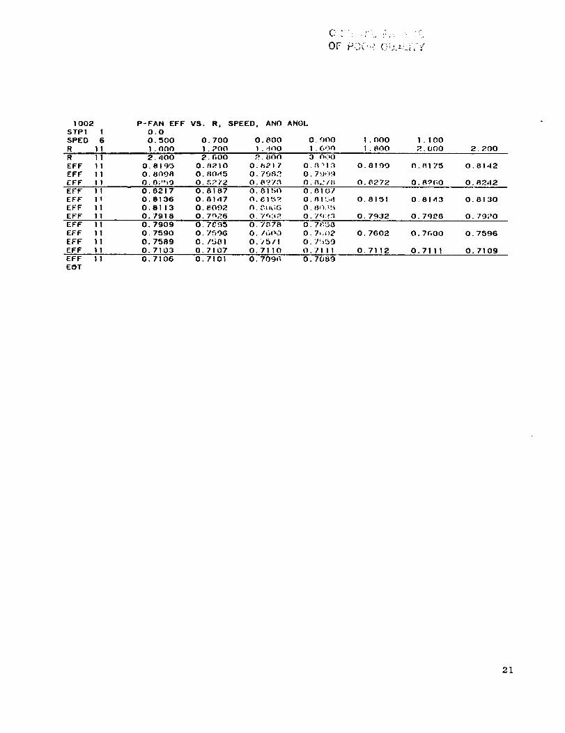
1002
STP1 1
SPED 6
R I1
P-FAN EFF VS. R, SPEED, AND ANGL0.0
0.500 0.700 0.800 0 <JO0
1. 000 1. 700 I. 4no I. 6,)n
1.000
1.800 2. 200
R
EFF
EFFEFF
11
11
II
11
2.400 2.600 2.600 3 _00
0.8193 0._210 0.8217 0.[_1_
O. SnO8 0.8045 0.1082 0,7_,_9
0.82ti9 0.£272 0.8?78 O.a2/_;
0 8100
0 8272
o.8142
0.A242
EFF
EFF
EFF
EFF
11I1
11
II
0.
O.
O.
O.
0217
8136
81137918
O. 8187 O. 81 ,_{£J O. 8107
0.8147 0.81_ 0._1t34
O. 8'.002 O.C.IJ_,;G O. W'L_',_
O, 7nR6 O. 701_2 O. /,_):f.";l
0.8130
0.7920
EFF
EFF
EFF
EFF
I1
11
I1
I1
0°
O.
0.
O.
7909
7590
7589
7103
0.7895 0.7878 0.7850
0.7_9G O. IGOO 0.7,._)2
0.1581 0.75/I 0.7ti59
0.7107 0.7110 0.7111
0 7602
0 7112
0.7_00
0.7111
EFF 11
EOT
0.7106 0.7101 0.709_ 0.7089
21

ORIGINAL p,_,_:,E _",_OF POOR QUALIi "_t"
1003
STP1 1SPED 6
R 11
P-FAN PR VS. R0 SPEED, AND ANGL
0.0O. 500 O. 700 O. 800
1 • 0()0 1 . 200 I ..400
l.lO0
_.NO0 2.200
R
PR
PR
PR
11
11
11
11
2.400 2._00 2,_00
1,57G6 1.5749 1.57Z3
1.5481 1.5410 1.5:_:T3
2.3420 2.3_7 _._)0
3.0()0
1 . _.$G'._O
1. ',_24.8
P. 3;"'3 !
PR 1 1
PR I I
PR 1 1
PR 1 1
PR 11
PR 11
PR 11
PR I I
PR 1 1
EOT
2.2915 2.2734 2.P6GI
2.8961 2.R_,;_O 2._9G4
2 8365 2.8P_,1 ?.8070
3 5714 3.5_,37 3.5_%_5
5068 3.4918 3 4754
3386 4.3337 4.3_74
2748 4.2(_0R ,I.2ff44
OBG4 5.0FI6 5.07_8
0?96 5.0171 5.0036
2._517
2.7L-_3
3,_5-'8
3.4 ,,_76
4. 3 I ,-')7
4. 2274
5. oc,q.o
4.9_91
2 0708
3 5435
2.8607
3.5327
2.8.493
3.5?04
22

7.0 ANALYTICAL BACKGROUND
7.1 Method of Map Generation
The fan geometry is defined implicitly by the design point input, and the user
selected option such as VIGV settings etc. The rotor design parameters are first
separated from those of the IGV and stator. The rotor is then analyzed separately and
the IGV and stator losses added on after the rotor calculation has been completed.
The min-loss line which forms the backbone of the map is assumed to pass through
the design point. This sets the optimum incidence angle on the rotor. The flow co-
efficient (Czl/UI) is assumed to remain constant with speed along the min-loss line2
for any given value of STPI or ROT1. The work coefficient (2g J DH/U2 ) is obtained
from the flow coefficient, rotor geometry, and rotor continuity. The rotor loss at
min-loss is obtained at the design point. This loss is assumed to be a function of
rotor inlet relative Mach number only since at design point the incidence is assumed
optimum. A curve of loss vs. rotor inlet relative Mach number is used with a scalar
to force the loss through the design point value. For off-design the incidence loss is
assumed to vary as (l-cosni) where n is determined from the NASA TASK II data of Ref. 4.
In order to indicate how different IG¥ positions are calculated, consider the
min-loss point on the 100% speed line. Assume an IGV setting of STPI= +20 ° is required.
The rotor exit relative flow angle (BETA2) is assumed to remain constant. The flow
coefficient and work coefficient are then calculated from the known value of ALPHA1 and
BETA1. A slight shift in the min-loss value of BETA1 and IGV position has been observed
in the data and is applied as a correction to BETA1 before the calculation is made.
The rotor continuity iteration to determine the axial valocity ratio across the
rotor is the key iteration in the program. The results of this iteration together with
the known flow angles sets the work coefficient at min-loss.
To determine the off-backbone characteristics, the angles ALPHA1 and BETA2 are
assumed equal to their min-loss values at the selected speed. A value of the work
coefficient is then chosen and the rotor continuity iteration carried out. The stator
and IGV losses are then added to obtain the stage performance.
23

_F _C_?_, :_i,:_ -:
7.2 Discussion of Variable Geometry Options for Axial Flow Fans
7.2.1 Variable Inlet Guide Vane (VIGV) Option
The VIGV option can be used to generate a set of off-design performance maps
for a user selected design point and set of IGV angles (i.e., STPI). The design
point is assumed to be at a zero value of STPI. The VIGV are assumed to be of the
type tested in the NASA TASK II program (Ref. 4), i.e., of a flap-type as sketched
in Figure 4. Since the IGV leading edge does not move, no IGV incidence loss is in-
cluded in the stage loss calculation. The inlet flow angle (ALPRAI) is somewhat less
than the IGV angle (STPI). As currently set the ratio of ALPHAI to STPI is about
0.775, as determined from the data of Ref. 4.
The nature of the flow modulation produced by the VIGV's is illustrated in
Figure 4. Let the nominal IGV setting represent the design point. Then at the same
speed and rotor incidence angle, the closed position results in a smaller value of
inlet axial velocity and, therefore, a smaller flow. A similar line of reasoning
leads to the conclusions that a negative IGV setting results in a flow increase.
The above conclusions can be made somewhat clearer and more quantative by
referring to the stage characteristlc sketch shown in Figure 5. The fan stage
characteristic can be expressed in either of the following two ways.
(1)
,
absolute inlet angle _
relative inlet angle
relative exit angle
where
2d

Positive IGV Nominal IGV Negative IGV'
u u
u 11 r
IGV
u
Rotor
Stator
Figure 4. Vector Diagram for Variable Inlet Guide Vanes (VIGV)
at Constant Rotor Incidence and Deviation Angle.
25

OF POOR QUAL[i_
O
n
,-4
2.0
=
q_
O
O
1.01
! I I
Min-Loss Locus
81 = 61.6 °
0 I0 0. i .5 2.0
STPI = +40 ° +20 ° 0 ° _I0 ° -20 °
I
m
Flow Coefficient
_1 = czl/u1
Figure 5. Stage Characteristics for VIGV Axial-Flow Fan.
26
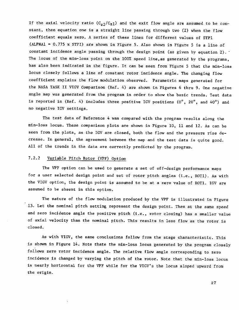
If the axial velocity ratio (Cz2/Czl) and the exit flow angle are assumedto be con-stant, then equation one is a straight line passing through two (2) when the flow
coefficient equals zero. A series of these lines for different values of STPI
(ALPHA1= 0.775 x STPI) are shownin Figure 5. Also shownin Figure 5 is a line of
constant incidence angle passing through the design point (as given by equation 2).
The locus of the min-loss point on the 100%speed line,as generated by the programs,has also been indicated in the figure. It can be seen from Figure 5 that the min-loss
locus closely follows a line of constant rotor incidence angle. The changing flow
coefficient explains the flow modulation observed. Parametric mapsgenerated for
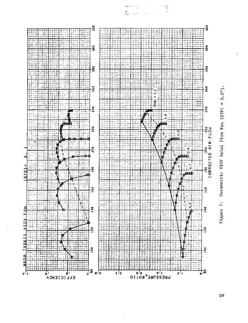
the NASATASKII VIGV Comparison (Ref. 4) are shownin Figures 6 thru 9. Onenegativeangle mapwas generated from the program in order to show the basic trends. Test data
is reported in (Ref. 4) includes three positive IGV positions (O°, 20° , and 40°) andno negative IGV settings.
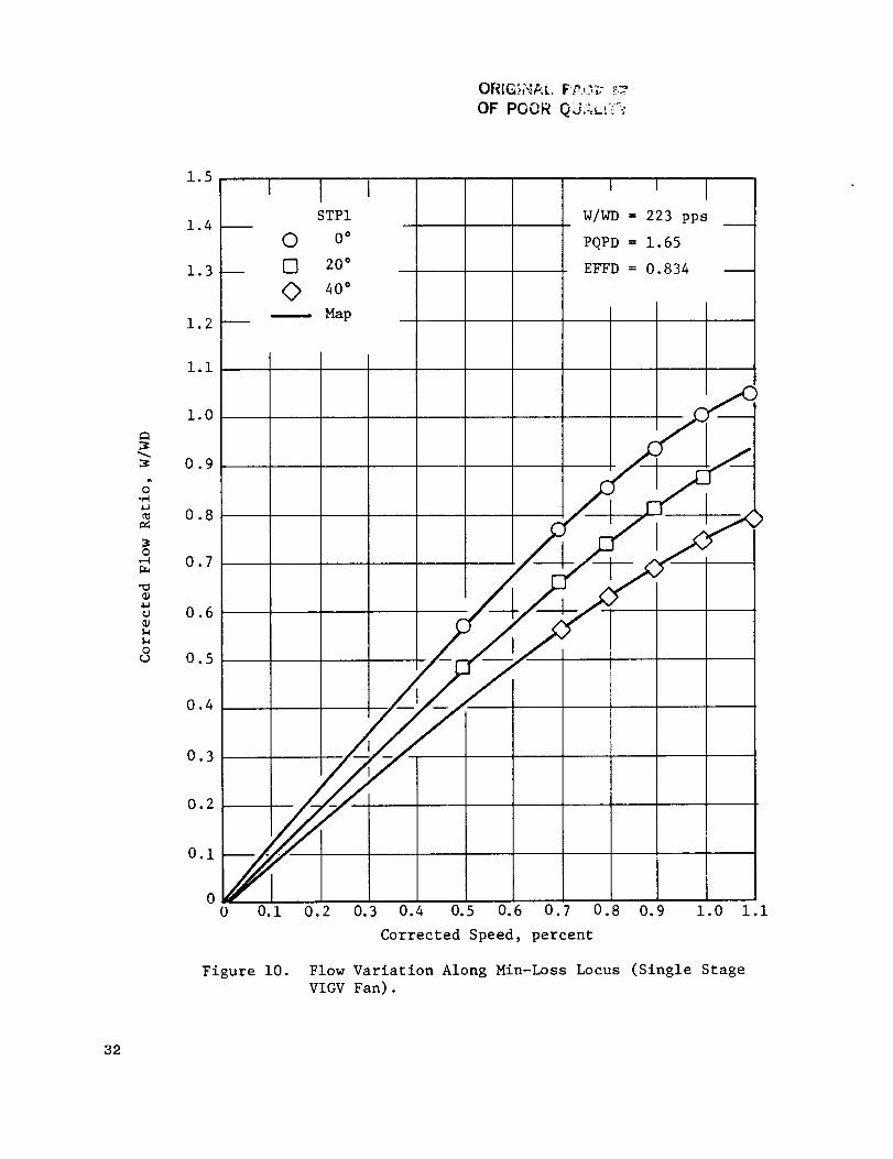
The test data of Reference 4 was comparedwith the program results along the
min-loss locus. These comparison plots are shownin Figure i0, ii and 12. As can be
seen from the plots, as the IGV are closed, both the flow and the pressure rise de-
crease. In general, the agreement between the map and the test data is quite good.
All of the trends in the data are correctly predicted by the program.
7.2.2 Variable Pitch Rotor (VPF) Option
The VPF option can be used to generate a set of off-design performance maps
for a user selected design point and set of rotor pitch angles (i.e., ROT1). As with
the VIGV option, the design point is assumed to be at a zero value of ROT1. IGV are
assumed to be absent in this option.
The nature of the flow modulation produced by the VPF is illustrated in Figure
13. Let the nominal pitch setting represent the design point. Then at the same speed
and zero incidence angle the positive pitch (i.e., rotor closing) has a smaller value
of axial velocity than the nominal pitch. This results in less flow as the rotor is
closed.
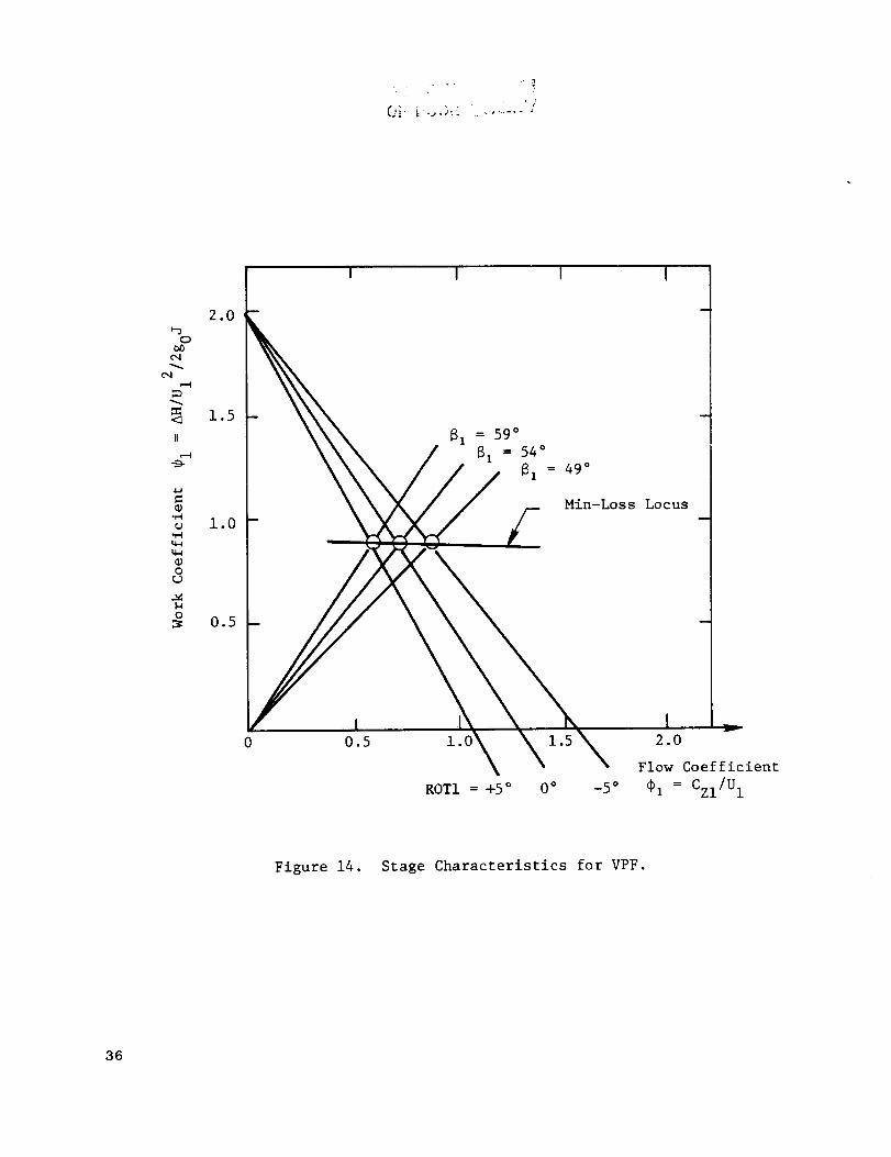
As with VIGV, the same conclusions follow from the stage characteristic. This
is shown in Figure 14. Note thate the min-loss locus generated by the program closely
follows zero rotor incidence angle. The relative flow angle corresponding to zero
incidence is changed by varying the pitch of the rotor. Note that the min-loss locus
is nearly horizontal for the VPF while for the VIGV's the locus sloped upward from
the origin.
2?

--H-!-i----_++-i.-_...._........ • .....
•i-L +-m-:T-
___4_._..L._J-a-,.._...L.r .-i.-;-_-dd--f +4- i- j-{--_" --r ;-. ":'"'L'-4!'_I,m-4-b-'4.,,,.,,,_J...... t "+'" i"!'_': :99";-I--ii
_-g-..+_tq-.d-'.--_-_-d+i---_-!--}--i-H...;-f-H-H-•-t"i-[-'-i-}'I-'1-ffi" _-rl"_l ..... i";'" q--!-1,--£Fi-r_+-<-" "--I "-+_-_'_ " '-ii ' -<'," , .......... ,'-T"_" "i'-_ ,"_
. LJ. 4.,4--.4-_4-L .'-L4.._ _-:_....L.L_...;-.:.i ..i-'.¢J 4.-_
k:ii ±ii_ :Z.i::i::L::::::::::::::::::::::::::::::::::::::::::
-',_LJL" ; .Li::: 'ti: LLi. i.;..i:_-_-T-_-<i _[ :!i i ...................] Eii!fiii!Ei!-,!..i._..,_...,-.Lj-i.- .L. :__..-_...... .-..... _4--. _L.J..._J_.L:._I_j ...i-;.-;- ,_.-.-4-a4.4 .i.L..•"--" _" -:-*"_-'_" "_-" ......... ' I:- _:-:_!- ''
t-I'-"I--'"'Tf" i..l. Tt" i Fi'-!"'T'i-i;".-Yi--_-:-- i_ F-r-
2 L 4--! .-•L. - k 4- _. - '-. 4- .
-i.-<.-L'-__.i..4-I4-#-:....:_....!4-''f!-i-_-,.-_.......,..+-_-.......-,-+-,---i--_i.L-'--:,_-_.......-;.-L.i-_-.-4-4- ........ -1-!---...--. _-e. t--i.._-.(-_ "r"_-t"
L.- _.L L L--,.. _,[email protected] _.... _..-L_.--_"I-7- . _,! i i,,t: ;'1._.a.i.; L.i.i_i ........ I,.iJ j.'.L_.L ._ i 'L.
. ..a J_-_.. ........ .......... - d- '
- =._,..+#¢--..._+--+,-:-_t........._!--i-It.'-.- i_-Z-]-,_...... r- -_T:I' L:: L.::7LZ'[: [Z ]3
._[.+-I ", ......... .._,, .2 "Z ....... ]"*_ !.
i-:-!-+:---:-ia> x:{-i >:!:::K:i::U
. i i. -:-:-_-i-._. i..i-. I]• i i "_ _ i , : ,i.:
/ ....... _--_..<-4!-_;.I%_+.f ._!_i--,|...-.i-•Y:i " i-ri _;"-' ......... _i........,..............._....
-. ....i....... I _" _ .I .. ........ :I............:::!:::i::::_z:_::7-::{-i- L_-i i _,-! : r:--i-F":---i---,i: ' _ '-, ........
....i.... _'£i-C .;._ .................. _....... -_..-_ ..,'
'-j.... ' -ik' +-i_.....: ,_+-_!-t :::::!•::;::::::[:.-_-:_::Z:=::L:_:r::_:li{:..._i::':::I::!4:i, :i ..............; ......... :- / _ " :;. t i ......
_I.'.LL._.Li._..'....:.......,_ .i .:::_) L_,L L I ;.i ..... Z!-i-k .. _,.i _ i _- __";"_""
-. :[.. ; _ ]:2) ;2,. -_.... j.
, i ........ ..L .-. i.-r-;. ---. - :_..... ].J-_--- i,--!--}.!-i _!--m -}..*' :-.i. 4. P4- '- Y' L#-i i q 4 ;i..:-;;' ;_ i :' _' 4_; ' :!'_.i.: _-.'.-.LJ._"___.i--_..... ...4 :-:.---.H--_-:-_....
" " . _-;- i, ......... _-h. I............ , ,, _-,_ ,_ ...... _-+........
i_ /TF4 ...... :r-,-i-'_ ; t FT-T ,_
.......,-i'_-H,-_........!--!---, +-I :_ > .......
. • i ! - ....... f -_ ........ r'!- , : _-- r........
•i--"--_i_,i:_ti:._:i:J::;-:L!:_:.:<__:J",.:::h:::::::i '1r( , m _ _
• '--,._.._t-4--i-F+---!";T: - 't: -T: - b .:!:-....-;z:.-_h;:;:_c:[_......._.i_..........i-+_.:L._4.....
L [ ...... .a.L_,.L t._._ -,- I,_.2..L _L..,(2..z.._ .........."i ! i . .L.-_L-L .J--L_L:- ........ ]_ t_l 4 ..... Lt,J-J.
"Z'!-""- -J-...L.L LJ ..t._. _. L.I_ _.L./-:- .LJ.LJ.T j. _ ..-'--l-l--i-..,+-g4..,- . ...-,-..... _._.. _4,-+.-_--.b_
..t.__=:..._..LL.,.44-4.--.--_......L..LL..:..L_i:::t...L_.'--_;.
...L.,-_.-,--' .......[:_i_:-_-. i..L -.,q--I-'-:!:4:_:-i-H-i ffH-+ :H:_:!
0"I 6' 8" Z'
&3N3 13 1-I-13
g-,o
o
1
II
28
C:. '
-*.' :-' ..... H.1-4 ............:.t, ......................i _._i--:i:i::::;
..... T'7-'l'" -!-'_ ' "" r i '5-/ _ r-:T 7_-i" _; "i i- -r ! i-I "1"t" _'_"b' ''I " ...... 47-! 'i! t"Y"t
-[ 4 l._. -'-'1 "_" _- J .LL:.. -..;..}....L..L: .i
i -i--'"i ...... "i _4"L '-i ' ',': " "4 ""-1 ; ;-i 4 ...... +-.. _ • _-;-4,-b4 ..... _..+.
_ i : i i i i ] J i !i i _ i '
_-I_..:._.4.% 4-H ;.-.---'.,-_-...--:-_.-_--._:...I-]-.-"....._=;.......h'."i-!......r ;'i'' "_'_i -;q'i""
li,_"_ : :iil ]i], :!:. ]iI !ii
-"i...t_-,4+-.4..i-I._.-:..i..+--i-.._.;-...--•_......t.:_..-i.:l:.i......i...l:_.: ...,-.-!--_-" --,-'_.....'H:-r -!-r-t -Ti-_-__WI-H ! +->_ ']ffi--
-q .........:'+-'.-_i-r....i,_--_'_-.'.I-_-*-!--.i. 4 ,_..... .L+-I- .-i.._..#._ ........ i_ii;, :! !! !::!:::!!_!! !!!
-!-,!.4..-,--4-...-F.;-t.,'- ......; ,.....J..........._......L.!___
-I_, ,T F:
....... ......._ r" :'-" I - ' "i_ f ............ _zj_lll_L" ", ...............i ....... -.q .....
-__-_-;'-irTi-_
-! : - r-: •• --ii-i ...... • -i........" i-_.-I._.
; 1i_ - .........._ -
..:_;.::i!:::/;i.::'L!::::.i::" !" _ !-i -_ i-i'i-;
" l "" ' ; '
•.._.]-".-:.-¢-+-.4.4-';..-:......! T F !-! -'" I- "_-'_"_'"II
7 i":_ !!-!:::::::
• r ; I .....L.._.....
::i! '-l-: 'JT-:i-bt! _:::::i:.L:i:::::::::::::::::::::::::::
"::_:[_:L:":::i:-'::.::X!-:_!!:i !i_ ,_,'v
.i;iZi-]11;.ill]i;.ilal.i
i ,"i7-' , ......".i._.-._i." .. i.
....! :...: .... * ...... L.i
...... : ........ I - :.-;--- i .... _'"_:][/j'[j,
i::', ,i/; : :i : :,.-].4!-'i " :..... i _..... ,_ "_ i" ' ; i ' :" ; :" i ....
_ ;4 :-r-r::::-:)::_:tI:;.,_! ::::;i:::_I::',::
-.i:-i _..-;ill-i! _!- :_ :-_ .'t.,_..:- [ LI.-L;L ! I-" "" ...... .; +.-!.'_i..l.
i;::!.::ii::::-'.:::L;.::i:.]::i:L ::'.i::i::.:":::_:'.:::i:::;:::i._::i:
; i ' ' _ 4.4 -_ ' ' _ _ r i . L .--,. .
-_- i-'i ..... ,--'-q ,'- -r"r" . -......',. ,........ u -.4.-: ..i-
:;:::;:::::!:::::':t/::-,,i..................... :- -"-',f{---i-rr]-
.-.q._..;- .!.J_-.L .L _tJ. _.' .:....: '..!....-'..i-.L.LJ
...L..L _ L .LJ..L-L- /_ . . .....' ._.d.,_rt:_4-+-L_.,.__:::::i':::t'•+.!.._-..!..
--r-...._-:-_":-H-!- 'Hti: , i-i.......:;._" "....................._ ,_-_--,.r_:,,,"!IT" ,,_ .r_ .... r...
' .......... -+-.i..4-- ........ .t4--4-.i-, ..i ..... i..._- . I-._-.F-:,- -;--!-.4-.i-4
-.[.H.-4.---H+t-- t-H-f- -r-4-H- Hq-.-l---H-I--I--_0"I 6" 8" &
&3N3131993
o
o
II
o
t-4
29

_,' 4-'4-. Je±.L.i- ,-l-J-t ...... T..I .;.[. _1 L.£-;_ .,.LJ...; ...-_-:-........ 4-4-,.--,...14..'-.-,..-_.L.._..J.._LLL.-_-i-..,.-'_q"-i+-...t..r.:-L _..i..¢..*.-i...-;._..i J 4-:-_.J-.-i...-_..-_._._.![i(iri _"?H ! .... :-! :+": i i-',-{-P: i i
........ .,-.. -1............ _.-_..:I-............... TZ-E,I.-,..._--L- "I"_'''T ..........T'r ....... ""T ..... f-r m" "'T .......
•-P-:--t-; ....... [-T "tTi" T i" ""T-"i':" T _-""_ __,._:._L.J_ , : _ _.i. + i. = ..,. _....:,._.,.: 1__.i.._]..i.._L_!.t _.._._ _,,... _,._... _., .; - i _ - -'-_- !.-!-!...-_; ,-]-.L..--j:.i...44. _- ....._ ..i._._.... Li._L ..
i Ti-- l i ! _ i I i
--!..Z.' L. 4-L.- - _..!.-i.- L L 4.........._.t .:...i ..L..', 1-4 4-.
:--i! :.-!i-.,.-_.-i'-...._'_::::::::::::::::::::::::,.,,:,:__,.:--_l,-,.Z.!...,-II._I:!:i:::::_i-.......i:-_' i _ .: .l : ._ .'.1 ,. i...._L Z-
.............- L...-L., : 1-i-" *.-,J,_.,-!-.-.-.,p.-.-i-_._:.__. L .J L.i..LJ._.., ....t ......_..! .I--L.L _-.P L -]-.
,-r-'.4-........i .--f] _._---_-.zJ.-l-.]-
: :f
.................] : :: .i_...:i: i '_.L_,4 _L 4 i---;-..........!_.4'-.-..i-,i.i.... i. ......ii,---! 4--i -
_r..r__!___,:__}_..._ L i-_"- _ i. }_..'.._;..i_r,_4_.'_, ......
......r- "-'_"I-_......._-_P'f--_ .......| _......_ "T i"........-4- _--;......... -@i- 1........ _- ,.[-i - ' "1- !--_ +--_-' -T-r "b'-7F:T" 1"T-r.:-,;f-lir it:: :: f_l
'* _---_- " _'-i i .......... t' "" -" 1"!"'!
........'.--i--i-l-i-!-;.-+_,:]-:i! f,- ii-!-,
. : i.[.._.i_;. : _.l i.._-:, ......
:.: ::i::::t t:::::::::t:i:i::i::...... +..................... _.'---I-..' i I--.-- -I.-i-!_
11:i ..................."*_ ........, _,:,_,.--I-
:_:::::::L+-':_-_ i]- ,ii:;:::.!::t::%b: :::::i:_; i:-4: ............._-.._- --__--- -,.i..._
.--L... ......._ _-,-i--_. _-'
•;.4-..i...4 % :i; ;-r-:-: ...... L-" _-'-f" '; |"
......,._.:....::-':-{!::::,:::;
'i-,_ ........ i-_ ,_1_ .......'" i "_ r " ' ! '4 !'-i" '" !..... L..I_
:-' :.............i....;_.-'___:j.:..1,i:!::"_ :.::;4 i[:-::
Z ;...._...... !-'H :,'_" _i-! l-r-' :-I_I - H ,
_:,: ;:::--_:_-_...,:;_' _l::.i..'_:-:i:i.:_..:i]:::;...:_::.t:_....L; .........*] _ ._ t _ :................... _ "i 'i+
" = _ J .-.4 • -L. ..... ' .... ...... _----- :.--, ill ..... _f_, t,,..j. ,I I . I : • _ ,
....., &,-...... '"H:,,-_ ....... F "_ .-_i-t "+ ii "' _:" 1-! + "':.-_ .i _-, 'ri--: .... ; i/i, :i i- r: , ,,'_:1] !- :; tl" i ?!.I.......I-........i..........k-_. _. : _'_..]..z......
- ---_--_ -_ : _.:-: _ --"-:-,1":-}-:__' ::2 :::,:_:_i::E:ZZ:L_. _::::::,'
_.i ;l;i!i,;iJ: i i _ 1 , , h i _ -
i-i-_-.i_,.i-::::::_-........:,,.......:--.'_._:......................,.__....
: .... _:.!!_:"...._:i::'_:::.:,::i:":::::::::::::::::::::::::: "-'t-i-i .... ..i-_,!IL;_ .., :., .... _-!_-.' ' _-_t,-:-"_- -i.... :_-.::_::.4::::,:.-,-::-4:* _--;*--_-;, _J! l:
' '. ] _ _ i _ !.L.,I..,_. " ' _ I i i ....,_..L..L.._.._- -.!--444--i -::Li::_:F:::Z.LT-:......,4. :: ......."'........
:]-:i:-_::i::i_:"_"_:;'i-_ _::i::: ::_-:i::i:FII"T" ', "i r-I"
0"I &" 8" _'
^9N3191_33
3O
OF POOR ....._"" ' :'
o0
0¢,,I+
II
,--1
V
0i.-I
i--I
¢.DI.-I;:>
.r..t
,.I,,J
C_
0},,.,
J._L.LJ _ .....i_J.L .:..I.L._ [.i...i.i.J.j..L.:........_......,.,_,......,_,.,.._,.,....,..,.,.......,...'._. L___;......._-.._-.i.!4---a.J.......L..i_L.+i..J.J_i....L_L_L_:+....i_L_2.._ _L..._._u+ &__i._,-i--;:i4 ,-_-[i ---i-i-r--i-i--:.
' i!I :'_',*:'I: :i : ' . i
...._..!.._-..... !.I.."i-!-_..........:--+' '- " '"
•--,-H+,'--:-f-* '_-- -i4+ - "+ _-:-i-: '_Y,--_........i:-!!d1i d _! 21 i--ili_
÷-b .i-r.-i-'di.-r+':i +--.q !--i:.i L !7 ' : :
_.+++-.-!-*-M._-.+--.,.+ -:-:-Li +---.---.-i-:.i--iliz ;ait::;;.l::: : , _.:
b-+ .6 +. +...a ,t L ........................ +......... _.J........
t t .................. I+ "'-i ..... 1 'I" .. +-'[ ...... _ i " ii-!-
-_-}-.Li- .4./_.*- t -L4.4- +i .+ ....... +" ..... "+"}:_:I....>...; ........; ; _t;-L.. - -i.._. _+.::!a a_-.4 _........ +i...._+._:_ ............I'. :
<...:. a.:..4.!-'-.-:ki-q_-,._ ............:= .........'',=-b--..a 4.-.bt ........... _.t : ... : . _ _+4...... '.}+:- --b .... _._.................._....i. L+. . .......
-T,--_ _-,11_ !!._ ! _' : ii........... ._ , ..!. ...2. L_L...2 ...... _ __ . ..
' r:-i 1- _'i- + -_ 7---1 , _ .............. P ; ,
, .-..--_ --_-t-_. _£TZ]_{:2::!2t:::_i i........... T £]7}.i_-...........1............ i-?-!;2_',_i, ' }+=', ii ...... ,1,
, : .... = _ _ .;.L.]£L-'I/ 12 Z 1.1i.2£i£i J .IY:'-ci-P" " ] P'i"_ 2.1 ...........:...:.L .i . ;.. :..!...
i-1 +'- ," + -i--...!-' -- - r..._ ._........ !...... ,-:- '.:"
......:4.......... i ! t.......i-', ...... !....... -<-r i ;............ , .......i! [ ...... 2_r_ : 772:1' :J22£Z:
_il ].. .+_...,._............ "......i -i........
"t-." 7-.i-_->'7 "_!-! '-i+ .-:-.2
..... i :...... 2_! L.. I
...,...........................,.......... , :i:i.:;.4̧,i-:-i-+-.: J--+ .... i "_ .i ...... - ' _ '
li .,_ _:_r.. ,::.
; .L.:_..I_: . . _1_ : i%'/"7 222 ............. '. , ; .... [ 1:22- i 2i; : ! _ ijl.[11. I_ . .
r
-H--H-:-;T-i-iri--,+_-_ _
....;-.!-.'.........-+--i.a-,--:-!--i._i.--.i!i::_:::!:!:::J:t-.............i-'"""r".-_--i-_---,+.-}.i-r
......."_+ _i-!-i ;-:tTL.:..I.;..J...2'..i!._......... ; _ ...."2_" k2. _L.
._h.L.ii i....... "-'-!+L'........ I'" : "'',"_" " ""'i" i. l_b. :.._i::' .'i...._L... :_..L.. i.._, i
:::i::i.:i:-,:I:::<::_::n::z:,_::_::::<i:-::_:: _-2 ::+::!:-:]::i:
:.::i_:::i:::::--i:_:_:::-::::'::.:'.-t.....'...... +-.,-<-.-_......:.-+................. i " _ -i--.!-.i----!,'-P :_::£-!--i.+.r--',+-H--t::!::i::i:_.+-!: I-. !-!-:r ,_-I-,2 i-Jr i _L. _._ i_L.2..J -i-"]'_l["[' ..i. '.l.i. ;.i.,_.L.a. LJ. i+l..
• . ,. -_ ..,._.'..i.._+.JH-!--l-Fr+.i,-H--ia--Lt-:-_-+ -. = :. :::t--H:+:gFi:i-!4:1:_:!__i:T-r _'i:.rt-+;'-:Fi:iI::t:i
O'l 6" e" g.A3N3IDI d-_3
C;7'_ 2 ...... ;
OF t'C_,:_ h._, :.-.i'_'I
o
m
:::'. 1::: ::::::::::::::::::::::::::::::::::::::::::::::::::::::::;::; ::_ ,: i "_:
............t'++t++f+,t.+.+t...._-+..-2-. --4 - .r--" ..... • +- '+-÷-4- -=-+ " +.....
..L;. +..._.+..;..+.--+-H.--_..-+-+;-_-_--_-'b_ i- :t_
...._...+..._...)... +...p..+.....+-.., ..+-....+._+...÷... +._ .+...+....+ -+ +
.ii +'+-ia ;-4ii at a., +..4. • .-+-+--4--_t t _ _ " _"+"J'.i I '_+'"":t .,L.+..a.= _ _
_..'-+...g.4. +- L.4- .-;---4-+- • L.L4. 1-4..L.. :+.-: ]d i_..,.. +--+.....4-.-a..+.-..-+-+-..4-44--,--+..,.-+.-+-4+' -,. -i -+ ,t...,._,..... , £; a• -+.+.--- ---+-q .4-.-: ++-- -4---..+ ."---t +'- t {-',- -_-+ -- '_ (....._.t++............L+--+_.-t,,,_,:L,--+:1.............................t ........... +_:........
....Lak+".....................__-._..__...a..ff..---_L_..{...t._"......."'+"_......._....._ + ........I£ ....+ _ -_
:',h: 2:::......L.4 • ..<:!7L4...;.-_..'.- 4-I.L .-i..+..L.,I--; :: :. 41, o
2{Z+I_'2 ::;2£ _ 27i2:..
........... +-........ +--+--+-+-_--. "-_+-i---- 22i2£;T £!£2;>+! t ! !-+:t:!+.rf! _-! ::g;q:-::::_q::::t
. .+-+*.J.-.;
....'.-. <--.--4--
•_ k "a a" I B ,m
.....+'-_- -.5.---4--]---'+--t ......... t ........... i-if- .......... ; 4 +'t-] "+"t-+-t-+-+ .......... +......... 4-- ....
'. _..a. I" +' +-_]_ -_ + "-- ""!"' -+"' -+'-+" ":" -7 a<...-r. +.. _..+-.._. +-_. -. +--+. +1 ............ 6r......., _ .'--:,........ :---t_--r ........ _i ...... +...... ++! .......... '-+-........ ' -_.--+...._....+-..#.- ,+. _-.; -..a..4 ........ 4. a .......... L _ 4+
t'a'i '" t ................... fi tt'_+1 ............. 1-* ':-'' '"{" ........ }'! -':" :'-_
I ...........................................t........................................................_.................. -_ --'-_....... ,d -_ _rt =i-ti :t--! _: .........;--!-..--t _ '-.!- -!-+--! !--]-_+!+,- •..... i t--I-+'+-I-t t" i:'-* ........ i--_}-_ ......... m:--!-_"l"t" T t t !-+.-_ -_ *-+ -e ...a_
' 11',2:: ..... ""+-', -',- v'"-'_'- "I ........... _ ......... _ *-+-::.:2_: t :::_:d:l:::: _:::;7:[:: :: ...............T 7 '" i -,. e............L..g.,..............._ : :_"_._L.,-.a._._.,.+__ ; : _-'-.i-..;..+-:.... .i.. ;..........2=.
....... :-- _ ............... +.-4 L.! .]..:.4. t"! 4.. +.--,-_+:................ •......... ---*..+- ; ....... +.......
................................................................. _-+-{t--+!' -_ ................... : +-;
........ + .......... +--+ +"+-'"_+-++ { + ++"+............................................. :.i:+:21"+'+I' -.+..+-.+..--i..÷--J---,_-.+-:- _22;- :222 o
: ' : + + | t ' + , ' ] + .... + ' : " ' + : -_'......,-+ t., +.+.r _......................... ;.-+.-+I L+-+4-+-+-+ • 7}_:: ................ ,u...................................... +.4 .............+..+_..+..+._.+._+..++..+Y_i :7........+. +........ -- ...,.. - -+--+, <+-,.'.-<...-+.4 -'...i.-; ..4-. '-.++-.++..._, ..+-,..+_ +',+ a.. -+........ ,+......... + .+. ,,._
...........+._+ ._+.- ..,-+-!..-t-.+-.f.-+-.t-.p.ff.t...bbf.f-t-..,.H..+. ++.........._...........+_+.++_: J ; ' + [ + ' : ;;71+_+I:T I+ :l:;i + : +
...... •............I :'I++ ............. ++- .._. -+ ._-.... -_- .+ •_............. _ .................. ..;...... ; .+..-i+ 2 + - 4. _, : 2_ . L+--2 .: _..J...<4..i ].L..* J__..._.J 2..+ • + + _+_2 ;_';£2,:2712.22 2_;_ ..: .+ .L... '--Z.-;.4..-- : 4"' .-4--+-4. i--; ; .'--;-_ ......... _ ........ ; ......
..... 2..i, .I '1..._i i +-<- ..i,I i I " --.+,_._ ".. L..;.+ I * : t i+,-.+ ._-..L.-;•+ .I+.+-..._ : I P ! :_" . .+-..L: ;a ' L,,-+i '...............i +a...i._..... 2...:-............. :. + +............ L +-2.. '..._ 2. 2.. _ .-2...+...;...2.. _ ..2 +.+t _ '. + ............. ;+"" "'4 t_.... , + .;..L ...... _.i..t.J...L.+' }. , + ' + + .+ -' +-.+.+ ......... +............. +.+.+._ ..........
" " > I 15 _ :'P e"t- " "_"-{- t { "t "+ "1 : e ......... ! "i [ ....7; ; ; ...... ;!i ......... :+ -i:, _ ....
• ,- +.......... _ ,..4 ......... +. + .;.+ -., + .+...._. - + ........................ _..+--.¢.-..... +.... : +.,... 4+.... +...;. : , , + • : . , +...r-+.,, <-r.-++-.---+-,.,..+-- ,---.............+. ,
I +- _ -t"l"e +-{ -+ _-+-t- ....... ÷ "- -i"f" _" -t ............ L_-.t-
[ I ; I: 'I+ ''t i .................................................................................................., ' L I : : { ' " : ' _ L : I I ' ] : I ; _ 0
.....- --. r...........rT :-" t .a. T TT ' ;"T " T + 27 .: -.+...... t ....... r - ....... =: :r bt -- , r-+_ ', t _ _ ' t"'::
............... _.+ + +.++. + ........+..+...,.++ .._ +.++.....+ . p.+ ..... - .. ........ +......_+_" ........ , +' ' i ' , ! { : : : t : : " " " ' ' I
........... _--+'+'-.--÷ ' "r", ...... +-+"'+ ","" -"! t +'' , ......... [" ................ I"-":"+
...... +.+ .+--+-.i .-_.............. 4--..._..÷-. + ............. _.-+, .............. I .+ _._ [ +_. + .. +...+.+_..,_.,.+....+..L_+. +r'-, ....... _..._..._. .____-L. .I._ ...... k- + " ÷"" t" a !-: "_........ -T
•;. _- 4+..-{..; a-...+ +..+a. --+---._ .4- J--_.-4- .÷ + +--.., ; . ..a +.+ ........ ,.+.. +-... + I=1• _ , t , , L t : : : ' I : _ .... I I _{_J {_
. ' ' I { .... _ ; ;2_I_ ::+ T : ? :] +.+, +..'. :..I._ +...+.=.,_.;..+.... ;-.+--+---'+ - .. .......... +. -...................... _............. _I.................. + ................ +--+11 I+ "+ Tit p I+ + I ....... t t "T' : + i'_--..... :.-+-_- i-+-_. Z££T<.+.-]:.+........ +-+............. ,...............+ .............. , -, ........
........+ ................+: t+-: +F+ 1:++f+, ,.++' ' }--+-.]-++-}.,.' .............i.. -i- .... ;+: ....... _......... . r,,L .......... e ; ......... +.-, +- -.+---+......... ,..+ ........ , +. +............... *.+ ........... 7.-? + .f .- ÷
;?++t-t + -:+t-,++tt?it.:+f,+-/_ "-: ................:i ....._.......................................... +.................. <_....7: : : ..... " : + ; .... -.... +........................../ r +........... +................ 1:[: • ....:2:::.:: ; + _• ....... + _ u.I
.. ; + " _.2.; ..........• +.... t" .i....... +.4.... +..+ , .+..+...... I--, , i i ' } ' i , ] _ _ , + rj _ ' + {.J
..................... +-4 .4--_........... _..+--I..+ _..... ........ :.= ..... +........ Iii...... : ................ ; .4.,. -...+..+ ........ +,.++.-L ' _++_ .......... I ..... + U ................ :
.......... I . _ _ _+- - 4. .+ ,-,...._.++ : . L '_ I- tt.-!--- 4 .+ - ; i.+ +- I_ .... +. a ..... + I_
:- +--].'--+--;-r++-i-t+-f-+ +f: t:-+++ t:a.,-,:-,_ ....: _ : --: g '_
....... P++I++I++I +-+; .I -, +-+.]...,--+-; .............+._;-+4,--:;]il .....+' ........................ --o..... _ +':'_ ,+..-!-;,. _+.++........... ,-...i ._. ++-*-+ ......._ ........ ........0 +.! I i i]+ - , (..)........... 3++ ......... +.+,.....2.+.. a•+ _.....,._+.2 .,._ ,. : .... • .... , _
-+-+ :- : ........ . +...+. + ]+++-+ _-,--+-+ ....... +
:+:,:+.,.,+++;;.........+++..........++.:_.... ; ..L . ...; +. +_......... i... 4- • -.+-.'.--i . _.-+. J...- ;. +.,i ..... , ......... -I. +4-_-+.-4-.++- ................ +--++-:_$ _ .....
: : : +?! "i_ t '-"!- .......i_! :,- '
i :!::I::!.' t:.::,',2. :!:::2:ii: .°_
<i,;
.... t+! ....4-4-4- ...... L4-1-.;-L.;..' .;-4-i- -:--i 4.+;-4 ;. +....... _";_i t _ + -_
-+++---+--+-+-.-+++'-.+,+. i::ii................ I-++-' -- t--t .......... +.. _+....+- ....... t..., - +..a ...... +. +., - +.-..+. + ............-I-+i----r-t--I-..--t_+-- H-4 c .:-t +.-!4-t i ---+*.'i....... +-,-+
0"_ 9"|
OIIU_ _ASS3_d
P0
0
+
II
=m
o
m0_
rD
Nm
m
..4
31
OF POOR Q J/_LF_ ,
G-,-4
ov-t_._
cJ_J
o
1.5I l I 1
STPI W/WD = 223 pps1.4
O O° PQPD = 1.65
1.3 -- _] 20o -- EFFD = 0.834
_o40 °
i. 2 Map _I.i
1.0
0.9
0.8
0.7
0.6
0.5
0.4
0.3
00.1
00 0.i 0.2 0.3 0.4 0.5 0.6 0.7 0.8 0.9 1.0 i.i
Corrected Speed, percent
Figure i0. Flow Variation Along Min-Loss Locus (Single StageVIGV Fan).
32

0O_
<_
<S
G-r..I
m
Q.I
m
1.5I i I
i. 4 - STPI
O 0 ° W/WD = 223 pps
1.3 [-] 20 ° PQPD = 1.65
<> 40 ° EFFD = 0.834Map
1.2 ----- i Ii
i.i
1.0
0.9
0.8
0.7
0.6
0.5
0.4
0.3
0.2
0.i
)
I
I
/
0
0 0.i 0.2 0.3 0.4 0.5 0.6 0.7 0.8 0.9 1.0 i.i
Corrected Speed, percent
Figure ii. Pressure Rise Variation Along Min-Loss Locus (Single
Stage VIGV Fan).
33

r.:1
r.:1
G
>,
=
u_
r..=1
1.5
1.3
i.i
0.9
0.7
0.5
' ' I ISTPI W/WD = 223 pps
© 0=
O 20° PQPD = 1.65
-- <> 40 o EFFD = 0.834
-- Map
0.3
0.i
0 0.i 0.2 0,3 0.4 0.5 0.6 0.7 0.8 0.9 1.0
Corrected Flow, percent
i.i
Figure 12. Efficiency Variation Along Min-Loss Locus (Single
Stage VIGV Fan).
34

_.4:..___. _
Positive Pitch Nominal Pitch Negative Pitch
w c
W//u
U
//
u
Rotor
Stator
Figure 13. Vector Diagr_ for Variable Pitch Rotor (VPF).
35
_no
eq
eq
ii
4J=
o
u_0o
o
I0.5
ROTI = +5 ° 0 ° -5 °
Min-Loss Locus
I
m
u
Ir
2.0
Flow Coefficient
_1 = CzI/UI
Figure 14. Stage Characteristics for VPF.
36

7.3 Discussion of Centrifugal Compressor Option
OR'C_,_._.L p?__._,_,
OF PO0_:: QUA!.h_y
7.3.1 Fixed Geometry Centrifugal Compressors
The centrifugal compressor option can be used to generate a set of off-design
performance maps for a user selected design point. The default settings assume a
geometry consisting of an impellor followed by a radial diffuser. The inlet swirl
angle is assumed to be zero and no provision is made for inlet guide vane loss.
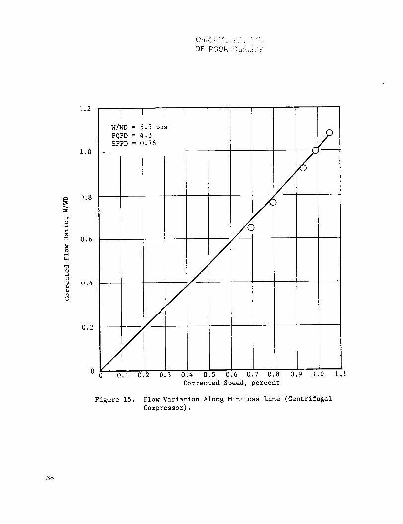
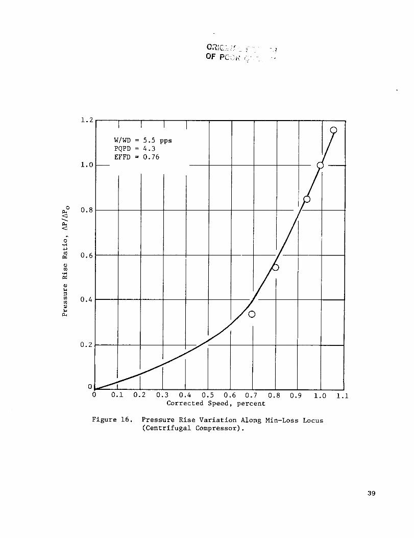
The test data of Reference 5 was compared with the program results for the
centrifugal compressor default case along the min-loss locus. These comparison plots
are shown in Figure 15, 16, and 17. In general, the agreement between the map and the
test data is fairly good. All of the trends in the data are correctly predicted by the
program.
7.3.2 Variable Inlet Guide Vanes (VIGV)
Centrifugal compressors frequently have a substantial degree of inlet swirl.
This swirl may result from the presence of an upstream axial compressor, or from the
presence of inlet guide vanes. In order to account for inlet swirl at the design point,
the program has provision for user selection of the design point inlet guide vane
position (STPID). The turning effectiveness of the IGV is assumed to 0.775 (i.e.,
ANGAI = 0.775 x STPI). No loss is charged to the IGV.
A variable inlet guide vane option (VIGV) has been provided for the centri-
fugal compressor just as for the axial flow fan. The most significant difference
between the axial and centrifugal VIGV options is that no loss is charged to the inlet
guide vanes in the latter case.
The nature of the flow modulation produced by the VIGV's for the centrifugal
machine is somewhat different from that for an axial machine. This can be made clear
by comparing the stage characteristics for the VIGV centrifugal compressor with those
of the axial flow fan which was shown in Figure 5.
The stage characteristic for a centrifugal compressor can be expressed in
either of the following two ways;
,?,
3?
o"
:30
Q;
o
1.2
1.0
0.8
0.6
0.4
I
W/WD = 5.5 pps
PQPD = 4.3
EFFD = 0.76
0.2
00 0.I
Figure 15.
0.2 0.3 0.4 0.5 0.6 0.7 0.8 0.9 1.0
Corrected Speed, percent
Flow Variation Along Min-Loss Line (.Centrifugal
Compressor).
i.i
38
o
<:_
<_
o"
{.I)
1.2
1.O P
0.8
0.6
0.4
0.2
00
I I I (3
W/WD = 5.5 pps 7
0.I 0.2 0.3 0.4 0.5 0.6 0.7 0.8 0.9 1.0 i.i
Corrected Speed, percent
Figure 16. Pressure Rise Variation Along Min-Loss Locus
(Centrifugal Compressor).
39

OF POOR QUALI]_'(
O
4.1
>-,U
tj
1.2
1.0
0.8
0.6
0.4
0.2
W/WD = 5.5 pps
PQPD = 4.3
EFFD = 0.76
0 0.2 0.4 0.6 0.8 1.0 1.2
Corrected Flow, percent
Figure 17. Efficiency Variation Along Min-Loss Locus (Centrifugal
Compressor).
40

Equations three and four reduce to equations one and two if the ratio of the inlet
to exit radii is set equal to unity.
If the axial velocity ratio (Cz2/Czl) and the exit flow angle are assumedto
be constant, then equation three is a straight line passing through two (2) when the
flow coefficient equals zero. A series of these lines for different values of STPI
(ALPHA1= 0.775 x STPI) are shown in Figure 18. Also shown in Figure 18 is a line of
constant incidence angle passing through the design point (as given by equation 4).
The locus of the min-loss point on the 100%speed line has also been indicated in the
figure. It can be seen from Figure 18that the min-loss locus closely follows a line
of constant rotor incidence angle. The flow modulation results from the change inflow coefficient along this locus.
Note that the value of the min-loss work coefficient increases as the flow coefficient
is reduced. This behavior contrast with that of the VIGV axial flow fan shownin
Figure 5 , where a reduction in the value of the min-loss flow coefficient resulted
in a reduction in the work coefficient. The difference is due to the presence of theinlet-to-exit radius ratio in equations three and four.
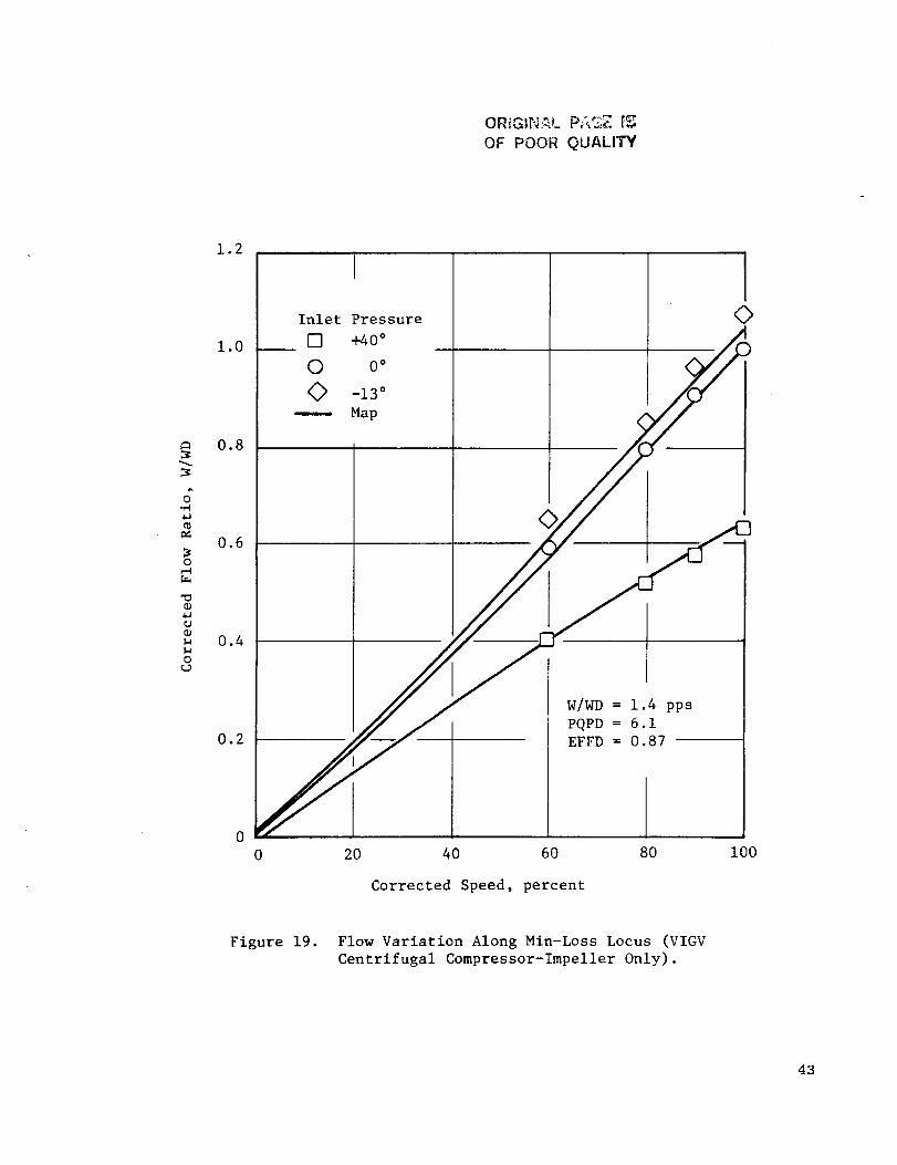
Performance mapswere generated for the VIGV centrifugal compressor reported
in Reference 6 . In this reference test data was reported for three IGV positions(-13 ° , 0°, 40°). The data as reported gives only the impeller performance. In order to
generate a map of the impeller performance the program source was edited to eliminate
the diffusser loss. The test data of Reference 6 was comparedwith the program resultsalong the min-loss locus. These comparison plots are shown in Figures 19, 20, and 21.
As can be seen from the plots as the IGV are closed, the flow is reduced and the impelle_
pressure rise increases. The agreement between the mapand the test data is fairly good.
According to Reference 6 , an additional loss of about 2.5% in impeller efficiency atthe STPI = 40° position occurred as a result of inlet flow distortion.
41

ORIGINAL rl-,_,;.OF POOR QUALITY
i-jO
¢,,Ic'q
v
II
=
rj
OL)
O
2.0
1.5
1.0
0.5
I R2/R I -- 2.225
Min-Loss Locus
o
STPI = 40 °
0.5 1.0 1.5
Flow Coefficient, _i = CzI/UI
2.0
Figure 18. Stage Characteristic for VIGV
(Centrifugal Compressor).
42
ORIGINAL Pf;,GE {:_
OF POOR QUALITY
1.2
o.i.I
o
0
00
0o
1.0
0.8
0.6
0.4
0.2
0
Inlet Pressure
[] +40 °
O 0 °
<> -13 °
------ Map
l<>
W/WD = 1.4 pps
PQPD = 6.1
EFFD = 0.87
0 20 40 60 80
Corrected Speed, percent
i00
Figure 19. Flow Variation Along Min-Loss Locus (VIGV
Centrifugal Compressor-Impeller Only).
43

1.2
1.O --
G.,iI
0.6
0.4
0.2
0
0
Inlet Pressure
_] +40 ° i
0 0° C
O -13° t
0 °
3 °
J_J W/WD = 1.4 pps
J20 40 60 80 i00
Corrected Speed, percent
Figure 20. Pressure Rise Variation Along Min-Loss Locus
(VIGV Centrifugal Compressor-Impeller Only).
44

OF POOI_ eL; _,Li',_'
o".,'-I,,l,,J
(,J
u,.-I
1.5
1.3
i.i
0.9
0.7
0.5
I I
Inlet Pressure
[] +40 °
© 0°
<> -13 =
-- Map
+40 °
-_ 00 -13°
-- O
/ I_ 2.5% IGV Loss Due to
Inlet Distortion
IW/WD = 1.4 pps
PQPD = 6.1EFFD = 0.87
0 0.i
Figure 21.
0.2 0.3 0.4 0.5 0.6 0.7 0.8 0.9 1.0
Corrected Flow, percent
Efficiency Variation Along Min-Loss Line (VIDV
Centrifugal Compressor-Impeller Only).
0
-<>
i.i
45

REFERENCES
io
o
.
*
,
a
Fishbach, Laurence H., and Caddy, Michael J., "NNEP: The Navy-NASA
Engine Program," NASA TM X-71857, 1975.
Fishbach, Laurence H., "Konfig and Rekonfig - Two Interactive Pre-
processing Programs to the NAVY/NASA Engine Program (NNEP)",
NASA TMX-82636, May 1981.
Converse, G.L. and Giffin, R.G., "Extended Parametric Representation
of Compressor Fans and Turbines", CMGEN User's Manual.
Bilwakesh, K.R., "Evaluation of Range and Distortion Tolerance for High
Mach Number Transonic Fan Stages, Task II Stage Data and Performance
Report for Undistorted Inlet Flow Testing," NASA CR-72787, January, 1971.
Rogers, C., "Typical Performance Characteristics for Gas Turbine Radial
Compressors," Journal of Engineering for Power, Trans. ASME, Series A,
Vol. 86., April 1964.
Rogers, C., "Impeller Stalling as Influenced by Diffusion Limitations,"
Journal of Fluids Engineering, Trans. ASME, March 1977.
46
DISIRIBUTION LIS1 - FINAL REPORTS - NAS3-23055
NASA Lewis Research Center
21000 Brookpark Road
Cleveland, OH 44135
Attn:
Report Control Office
Library
M. J. Hartmann
L. W. Schopen
H. Mark
D. N. Bowdltch
D. L. Nored
L. D. Nichols
C. L. Ball
L. E. Macloce
H. E. Rohllk
L. H. Fishbach
Ma% 1 Stop
60-1
60-3
3-7
500-305
501-12
86-I
301-2
60-2
60-5
6-B
6-I0
501 -I0
NASA Scientific and Technical Information FacilityP.O. Box 875
Baltlmore/Washlngton International Airport, MD 21240
Attn: Accesslon_ng Department
No. of Copies
l
3
1
1
1
1
l
l
2
l
2
25
25
47

DISTRIBUTIONLIS1 (CONT'D)
Onecopy each to the following.
Mr. E. G. Blev%nsAFWAL/POTAWrlght-Patterson AFB, OH 45433
Ms. Bobbye Ross
AIResearch Manufacturing
Company of ArizonaP.O. Box 5217
Phoenix, AZ 85010
Mr. Len Levlne
AVCO-Lycomlng Division
550 South Main Street
Stratford, CT 06497
Mr. Oushyant R. Arab
Senior Engineer
Propulsion - R&D
Beech Aircraft Corporation
Wichita, KS 67201
Mr. Erol Onat
The Boeing CompanyP.O. Box 3999
Seattle, WA 98124
Mr. Paul W. Relsdorf
Technical Center
Caterpillar Tractor Co.lO0 N. E. Adams Street
Peoria, IL 61629
Mr. Gerald W. White
Senior Propulsion Systems Analyst
Office of Scientific and Weapons Research
Central Intelligence Agency
Washington, DC 20505
Mr. Richard A. Sulkoske
Supervisor - Preliminary DesignDetroit Diesel Allison
P.O. Box 894
Indianapolis, IN 46206
48
Mr. Helner O. Becker
Project Manager
Engineering Systems
Dresser Industries, Inc.
Dresser Computer Services Div_slonP.O. Box ?96369
Dallas, TX 753?9
Mr. M. A. Romano
Advanced Products
Fairchild Republic Company
Farmlngdale LI, NY I1735
Mr. Lynn Marksberry
Fluldyne
5900 Olson Memorial Highway
Minneapolis, MN 55422
FTD/SDNP
Attn: M. A. Pennuccl
Wrlght-Patterson AFB, OH 45433
Ms. Joyce R. Stlnson, Manager
Systems Computations
Building 240G5General Electric Co.
lO00 Western Avenue
Lynn, MA OlglO
Mr. Ronald E. Feddersen
Mall Stop C42-05
Grumman Aerospace Corporation
Bethpage, NY ll?14
Mr. Ivan C. Oelrlch
IDA/STD
IBOl N. Beauregard Street
Alexandria, VA 22311
Mr. J. F. Stroud
Lockheed-Callfornla CompanyBurbank, CA 91520
Mr. John C. Donohoe
Martin Marietta AerospaceMall Point 306
Orlando Division
P.O. Office Box 5837
Orlando, FL 32855
3
EugeneE. Covert, Sc.D.Professor and Director
Department of Aeronautics and Astronautics
Center for Aerodynamic Studies
Massachusetts Institute of TechnologyCambrldge_ MA 02139
Dr. Robert T. Tausslg
Director of Energy TechnologyMathematical Sciences North West, Inc.
2755 Northup Way
Bellevue, WA 98004
Mr. Donald C. Bingaman
McDonnell Douglas Corporation271/C9A
P.D. Box 516
St. Louis, MO 63166
NASA Ames Research Center
237-11/Tom Galloway
Moffett Field, CA 94035
National Aeronautics and Space Administration
George C. Marshall Space Flight CenterAttn: PD31-78-41
Marshall Space Flight Center, AL 35812
NASA Langley Research Center
249/Shelby J. Morris
Hampton, VA 23665
Mr. Michael CaddyCode 6052
Naval Air Development CenterWarmlnster, PA 18974
Mr. Paul Piscopo
Naval Air Propulsion Center
P.O. Box 7176
Trenton, N3 OB62B
F. 3. O'Brlmskl, Commander
Naval Air Systems CommandAIR-5284C2/JEL
Department of the Navy
Washington, DC 20361
Professor Thomas Houllhan
Code 69 HM
Naval Post Graduate School
Monterey, CA 93940
Mr. Andre By
Northern Research and Engineering Company
3g Olympia Avenue
Woburn, MA OI801
Mr. Arlf Dhanldlna, 3813/82
Propulsion Research
Northrop Aircraft Division
One Northrop Avenue
Hawthorn, CA 90250
Mr. Douglas Lee, 382B/52
Advanced Propulsion/Thermal Analys_s
Northrop Aircraft Dlvls_on
One Northrop Avenue
Hawthorn, CA 90250
Mr. Henry Snyder
Pratt & Whitney Aircraft Group
Engineering Computer Applications
Government Products Division, M/S 712-28
P.O. Box 2691
West Palm Beach, FL 33402
Mr. Robert Howlett
Pratt & Whltney Aircraft Division400 Main Street
Mall Stop EBIFI
East Hartford, C_ 06108
Mr. Larry Carroll
Propulsion Dynamics Inc.2200 Somerville Road
Annapolis, MD 21401
Mr. William E. Flaus-O/7l B/6
North American Aircraft Division
Rockwell International
4300 East Fifth Avenue
P.O. Box 125g
Columbus, OH 43216
Mr. Larry M111er
Aerospace Marketing Manager
Rosemount IncorporatedP.O. Box 959Burnsvllle, MN 55337
Mr. Nate Anderson
Mall Zone E-9
Solar Turbines International
P.O. Box B0966
San Diego, CA g2138
49

4
Professor I-Dee ChangDepartment of Aeronautics and AstronauticsWilliam F. Durand BuildingStanford UniversityStanford, CA 94305
Mr. Mark A. ChappellSverdrup Technology Inc.Mall Stop 500Arnold Air Force Station, TN 37389
Mr. John J. FoxTeledyne CAE1330 Laskey RoadP.O. Box 697!Toledo, OH 43612
CommanderUSArmy Aviation Research & Development
CommandAttn: DRDAV-DP/DennlsEnders4300 Goodfellow Blvd.St. Louis, MO 63120
Mr. Mike Galvls - DAVDL-AIL-ATPApplied Technology LaboratoryU.S. Army Research Laboratory (AAVRADOM)Fort Eustls, VA 23604
Dr. Paul C. Glance
Chief, Engine Function
Department of The Army
U.S. Army _ank-Automotlve Research
and Development Command
Warren, MI 48090
Dr. Walter Obrlen
Mechanical Engineering Dept.
Virginia Polytechnic Institute
Blacksburg, VA 2406l
Dr. Reginald G. Mitchlner
Associate Professor of Mechanical Engineering
Virginia Polytechnic Institute and StateUniv.
Blacksburg, VA 24061
Mr. W. M. Rhoades
Manager, Propulsion and Thermodynamics
Vought Corporation
P.O. Box 225907
Dallas, TX 75265
Mr. Gerald J. Herman
Williams Research Corporation
2280 West Maple Road
Walled Lake, MI 48088
50


![Thermodynamic Properties of Natural Gas Mixtures …€¦ · instance, AGA NX-19 [4] and MGERG-88 [5] are used in custody transfer for calculating compressibility factors of natural](https://img.pdfslide.us/doc/110x75/5ac7fa6b7f8b9a40728c497d/thermodynamic-properties-of-natural-gas-mixtures-instance-aga-nx-19-4-and.jpg)