Embed Size (px)
Citation preview
National Aeronautics and Space AdministrationSL2019
NASAStudent Launch
Handbook andRequest forProposal

Note: For your convenience, this document identifies Web links when available. These links are correct as of this publishing; however, since Web links can be moved or disconnected at any time, we have also provided source information as available to assist you in locating the information.
i
Table of Contents
Timeline for NASA Student Launch .............................................................................................................. 1Acronym Dictionary ...................................................................................................................................... 2
Proposal/Statement of Work
Design, Development, and Launch of a Reusable Rocket and Payload Statement of Work (SOW) ........... 4General Requirements .......................................................................................................................... 5Vehicle Requirements ............................................................................................................................ 6Recovery System Requirements ......................................................................................................... 10Payload Experiment Requirements ......................................................................................................11Safety Requirements ........................................................................................................................... 12
Proposal Requirements ............................................................................................................................. 14
Project Milestones: Criteria and Expectations
Preliminary Design Review (PDR) Vehicle and Payload Experiment Criteria ............................................ 18Critical Design Review (CDR) Vehicle and Payload Experiment Criteria .................................................. 22Flight Readiness Review (FRR) Vehicle and Payload Experiment Criteria ............................................... 27Launch Readiness Review (LRR) Vehicle and Payload Experiment Criteria ............................................ 32Post Launch Assessment Review (PLAR) Vehicle and Payload Experiment Criteria ................................ 32STEM Engagement Activity Report ............................................................................................................ 33
Safety
High Power Rocket Safety Code ............................................................................................................... 36Minimum Distance Table ............................................................................................................................ 38
Awards
College and University Division Awards ..................................................................................................... 41Middle School and High School Division Awards ....................................................................................... 42

1
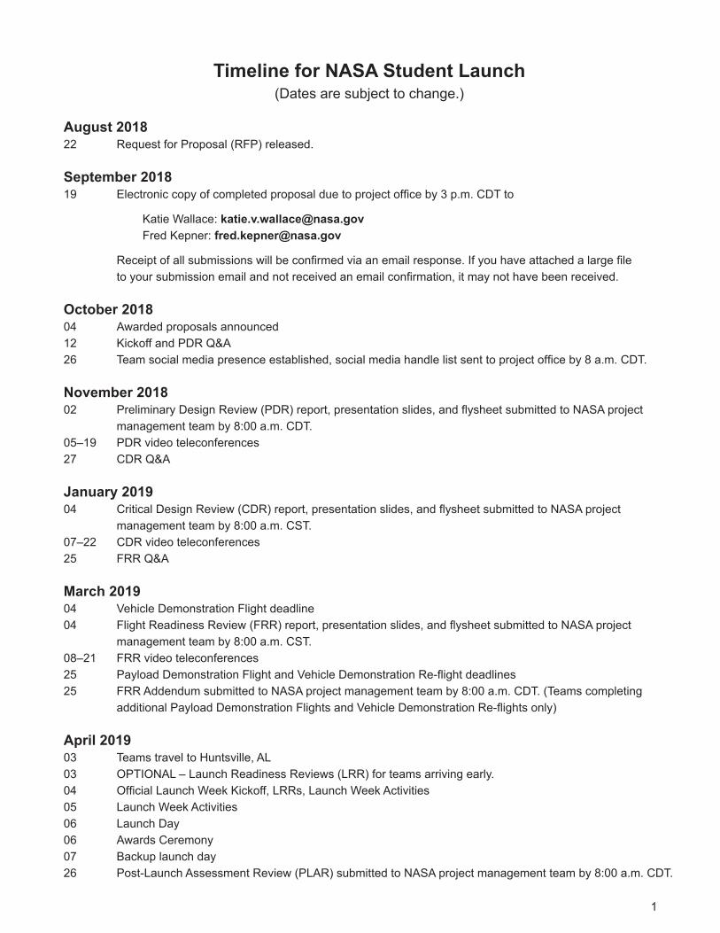
Timeline for NASA Student Launch(Dates are subject to change.)
August 201822 Request for Proposal (RFP) released.
September 201819 Electroniccopyofcompletedproposalduetoprojectofficeby3p.m.CDTto
Katie Wallace: [email protected] Kepner: [email protected]
Receiptofallsubmissionswillbeconfirmedviaanemailresponse.Ifyouhaveattachedalargefiletoyoursubmissionemailandnotreceivedanemailconfirmation,itmaynothavebeenreceived.
October 201804 Awarded proposals announced12 Kickoff and PDR Q&A26 Teamsocialmediapresenceestablished,socialmediahandlelistsenttoprojectofficeby8a.m.CDT.
November 201802 PreliminaryDesignReview(PDR)report,presentationslides,andflysheetsubmittedtoNASAproject
management team by 8:00 a.m. CDT.05–19 PDR video teleconferences27 CDR Q&A
January 201904 CriticalDesignReview(CDR)report,presentationslides,andflysheetsubmittedtoNASAproject
management team by 8:00 a.m. CST.07–22 CDR video teleconferences25 FRR Q&A
March 201904 Vehicle Demonstration Flight deadline04 FlightReadinessReview(FRR)report,presentationslides,andflysheetsubmittedtoNASAproject
management team by 8:00 a.m. CST.08–21 FRR video teleconferences25 PayloadDemonstrationFlightandVehicleDemonstrationRe-flightdeadlines25 FRR Addendum submitted to NASA project management team by 8:00 a.m. CDT. (Teams completing
additionalPayloadDemonstrationFlightsandVehicleDemonstrationRe-flightsonly)
April 201903 Teams travel to Huntsville, AL03 OPTIONAL–LaunchReadinessReviews(LRR)forteamsarrivingearly.04 OfficialLaunchWeekKickoff,LRRs,LaunchWeekActivities05 Launch Week Activities06 Launch Day06 Awards Ceremony07 Backup launch day26 Post-Launch Assessment Review (PLAR) submitted to NASA project management team by 8:00 a.m. CDT.
2
Acronym Dictionary
AGL = Above Ground Level
APCP = Ammonium Perchlorate Composite Propellant
CDR = Critical Design Review
CG = Center of Gravity
CP = Center of Pressure
EIT=ElectronicsandInformationTechnology
FAA = Federal Aviation Administration
FEA = Future Excursion Area
FN = Foreign National
FRR = Flight Readiness Review
HEO = Human Exploration and Operations
LCO=LaunchControlOfficer
LRR = Launch Readiness Review
MSDS = Material Safety Data Sheet
MSFC = Marshall Space Flight Center
NAR = National Association of Rocketry
PDR = Preliminary Design Review
PLAR = Post Launch Assessment Review
PPE = Personal Protective Equipment
RDO=RemoteDeploymentOfficer
RFP = Request for Proposal
RSO=RangeSafetyOfficer
SLI=StudentLaunchInitiative
SLS = Space Launch System
SME = Subject Matter Expert
SOW = Statement of Work
STEM = Science, Technology, Engineering, and Mathematics
TRA = Tripoli Rocketry Association
ProposalStatementof Work
4
Design, Development, and Launch of a Reusable Rocket and Payload Statement of Work (SOW)
1. Activity Name: NASA Student Launch
2. GoverningOffice:NASAMarshallSpaceFlightCenterAcademicAffairsOffice
3. Period of Performance: Eight (8) calendar months.
4. IntroductionTheAcademicAffairsOfficeatNASAMarshallSpaceFlightCenter(MSFC)seeksproposalsfromcollegesanduniversitiestoconducttheNASAUniversityStudentLaunchInitiative(USLI)andqualifiedhighschoolsandmiddleschoolstoconducttheNASAStudentLaunchInitiative(SLI)duringthe2018-2019academicyear.The NASA Student Launch (SL) is a research-based, competitive, and experiential learning project that pro-vides relevant and cost-effective research and development. SL connects learners, educators, and communi-ties in NASA-unique opportunities that align with Science, Technology, Engineering, and Mathematics (STEM)Challenges. The activity is supported by the Human Exploration and Operations (HEO) Mission Directorate,OfficeofSTEMEngagement,andcommercialindustry.
Student Launch reaches a broad audience of colleges, universities, and secondary institutions across thenationinan8-monthcommitmenttodesign,build,launch,andflyapayload(s)andvehiclecomponentsthatsupport NASA research on high-power rockets. The College/University Division challenge is based on teamselection of one of the following experiment options: 1) deployable rover and soil sample collection or2) deployable unmanned aerial vehicle and delivery of a navigational beacon. Teams may incorporate addi-tional research through the use of a separate payload if desired. Secondary experiments must be approvedbyNASA.Inaddition,theteammustprovidedocumentationonadditionalcomponentsandsystemsinallreports and reviews. High School/Middle School division teams may select one of the two NASA experimentoptions or they may design their own science or engineering experiment. Awards are presented to teams inbothdivisionsatanAwardsCeremonyduringLaunchWeek.Moreinformationonspecificawardscanbefound on pages 41 and 42.
Proposals to participate in the NASA Student Launch Projects College/University Division will be accepted from any US college or university. Proposals to participate in the High School/Middle School Division will onlybeacceptedfromteamswhosuccessfullycompletedStudentLaunchasafirst-yearteamin2017-2018orhavequalifiedforStudentLaunchJourneymanstatus.JourneymanstatusshallbegiventoHighSchool/Middle School Division teams who meet the following requirements: 1) have participated in Student Launch for four or more consecutive years, 2) satisfactorily completed Student Launch during the previous academic year, and 3) the team educator has completed the NASA Student Launch Advanced Rocketry Workshop. Institutionsproposingforeitherdivisionarepermittedtosubmitproposalsformultipleteamsbutamaximumof one proposal per institution will be selected.
After the competitive proposal selection process, teams complete a series of design reviews. These reviews mirror the NASA engineering design lifecycle, providing a NASA-unique experience that prepares students for the HEO workforce. Teams must successfully complete a Preliminary Design Review (PDR), Critical Design Review (CDR), Flight Readiness Review (FRR), and Launch Readiness Review (LRR) which include safety briefings,analysisofvehicleandpayloadsystems,andflighttestdata.Eachteammustpassareviewin
5
order to move to a subsequent review. Teams will present their PDR, CDR, and FRR to a review panel of sci-entists, engineers, technicians, and educators via video teleconference. Review panel members, the Range SafetyOfficer(RSO),andSubjectMatterExperts(SME)providefeedbackandaskquestionsinordertoincreasethefidelitybetweentheteam’sworkandresearchobjectives,andwillscoreeachCollege/UniversityDivision team according to a standard scoring rubric. High School/Middle School Division teams complete the same milestones but are not in competition and are not scored.
The requirements for NASA Student Launch are as follows:
1. General Requirements1.1. Students on the team will do 100% of the project, including design, construction, written reports, pre-
sentations,andflightpreparationwiththeexceptionofassemblingthemotorsandhandlingblack powder or any variant of ejection charges, or preparing and installing electric matches (to be done by theteam’smentor).
1.2. The team will provide and maintain a project plan to include, but not limited to the following items: proj-ect milestones, budget and community support, checklists, personnel assignments, STEM engagement events, and risks and mitigations.
1.3. ForeignNational(FN)teammembersmustbeidentifiedbythePreliminaryDesignReview(PDR)andmayormaynothaveaccesstocertainactivitiesduringlaunchweekduetosecurityrestrictions.Inaddition,FN’smaybeseparatedfromtheirteamduringcertainactivities.
1.4. The team must identify all team members attending launch week activities by the Critical Design Review (CDR). Team members will include:1.4.1. Students actively engaged in the project throughout the entire year.1.4.2. One mentor (see requirement 1.13).1.4.3. No more than two adult educators.
1.5. The team will engage a minimum of 200 participants in educational, hands-on science, technology, engineering,andmathematics(STEM)activities,asdefinedintheSTEMEngagementActivityReport,by FRR. To satisfy this requirement, all events must occur between project acceptance and the FRR due date and the STEM Engagement Activity Report must be submitted via email within two weeks of the completion of the event. A sample of the STEM Engagement Activity Report can be found on page 33 of the handbook.
1.6. The team will establish a social media presence to inform the public about team activities.
1.7. TeamswillemailalldeliverablestotheNASAprojectmanagementteambythedeadlinespecifiedinthehandbookforeachmilestone.Intheeventthatadeliverableistoolargetoattachtoanemail,inclusionofalinktodownloadthefilewillbesufficient.
1.8. All deliverables must be in PDF format.
1.9. Ineveryreport,teamswillprovideatableofcontentsincludingmajorsectionsandtheirrespectivesub-sections.
1.10. Ineveryreport,theteamwillincludethepagenumberatthebottomofthepage.
6
1.11. The team will provide any computer equipment necessary to perform a video teleconference with the review panel. This includes, but is not limited to, a computer system, video camera, speaker telephone, andasufficientInternetconnection.Cellularphonesshouldbeusedforspeakerphonecapabilityonlyas a last resort.
1.12. AllteamswillberequiredtousethelaunchpadsprovidedbyStudentLaunch’slaunchservicespro-vider.Nocustompadswillbepermittedonthelaunchfield.Eightfoot1010railsand12foot1515railswill be provided. The launch rails will be canted 5 to 10 degrees away from the crowd on launch day. The exact cant will depend on launch day wind conditions.
1.13. Eachteammustidentifya“mentor.”Amentorisdefinedasanadultwhoisincludedasateammember,who will be supporting the team (or multiple teams) throughout the project year, and may or may not be affiliatedwiththeschool,institution,ororganization.Thementormustmaintainacurrentcertification,and be in good standing, through the National Association of Rocketry (NAR) or Tripoli Rocketry Asso-ciation(TRA)forthemotorimpulseofthelaunchvehicleandmusthaveflownandsuccessfullyrecov-ered(usingelectronic,stagedrecovery)aminimumof2flightsinthisorahigherimpulseclass,priorto PDR. The mentor is designated as the individual owner of the rocket for liability purposes and must travel with the team to launch week. One travel stipend will be provided per mentor regardless of the number of teams he or she supports. The stipend will only be provided if the team passes FRR and the team and mentor attend launch week in April.
2. Vehicle Requirements2.1. The vehicle will deliver the payload to an apogee altitude between 4,000 and 5,500 feet above ground
level(AGL).Teamsflyingbelow3,500feetorabove6,000feetonLaunchDaywillbedisqualifiedandreceivezeroaltitudepointstowardstheiroverallprojectscore.
2.2. Teams shall identify their target altitude goal at the PDR milestone. The declared target altitude will be usedtodeterminetheteam’saltitudescoreduringLaunchWeek.
2.3. Thevehiclewillcarryonecommerciallyavailable,barometricaltimeterforrecordingtheofficialaltitudeused in determining the Altitude Award winner. The Altitude Award will be given to the team with the smallestdifferencebetweentheirmeasuredapogeeandtheirofficialtargetaltitudeonlaunchday.
2.4. Each altimeter will be armed by a dedicated mechanical arming switch that is accessible from the exterioroftherocketairframewhentherocketisinthelaunchconfigurationonthelaunchpad.
2.5. Each altimeter will have a dedicated power supply.
2.6. Each arming switch will be capable of being locked in the ON position for launch (i.e. cannot be disarmed duetoflightforces).
2.7. Thelaunchvehiclewillbedesignedtoberecoverableandreusable.Reusableisdefinedasbeingabletolaunchagainonthesamedaywithoutrepairsormodifications.
2.8. The launch vehicle will have a maximum of four (4) independent sections. An independent section is definedasasectionthatiseithertetheredtothemainvehicleorisrecoveredseparatelyfromthemainvehicle using its own parachute.2.8.1. Coupler/airframeshoulderswhicharelocatedatin-flightseparationpointswillbeatleast
1 body diameter in length.
7
2.8.2. Noseconeshoulderswhicharelocatedatin-flightseparationpointswillbeatleast½bodydiameter in length.
2.9. The launch vehicle will be limited to a single stage.
2.10. Thelaunchvehiclewillbecapableofbeingpreparedforflightatthelaunchsitewithin2hoursofthetimetheFederalAviationAdministrationflightwaiveropens.
2.11. Thelaunchvehiclewillbecapableofremaininginlaunch-readyconfigurationonthepadforaminimumof 2 hours without losing the functionality of any critical on-board components.
2.12. Thelaunchvehiclewillbecapableofbeinglaunchedbyastandard12-voltdirectcurrentfiringsystem.ThefiringsystemwillbeprovidedbytheNASA-designatedlaunchservicesprovider.
2.13. The launch vehicle will require no external circuitry or special ground support equipment to initiate launch (other than what is provided by the launch services provider).
2.14. The launch vehicle will use a commercially available solid motor propulsion system using ammonium perchloratecompositepropellant(APCP)whichisapprovedandcertifiedbytheNationalAssociationofRocketry (NAR), Tripoli Rocketry Association (TRA), and/or the Canadian Association of Rocketry (CAR).
2.14.1. Final motor choices will be declared by the Critical Design Review (CDR) milestone.2.14.2. AnymotorchangeafterCDRmustbeapprovedbytheNASARangeSafetyOfficer(RSO)
and will only be approved if the change is for the sole purpose of increasing the safety margin. Apenaltyagainsttheteam’soverallscorewillbeincurredwhenamotorchangeismadeafterthe CDR milestone, regardless of the reason.
2.15. Pressure vessels on the vehicle will be approved by the RSO and will meet the following criteria:2.15.1. The minimum factor of safety (Burst or Ultimate pressure versus Max Expected Operating
Pressure) will be 4:1 with supporting design documentation included in all milestone reviews.2.15.2. Each pressure vessel will include a pressure relief valve that sees the full pressure of the tank
andiscapableofwithstandingthemaximumpressureandflowrateofthetank.2.15.3. Full pedigree of the tank will be described, including the application for which the tank was
designed, and the history of the tank, including the number of pressure cycles put on the tank, by whom, and when.
2.16. The total impulse provided by a College or University launch vehicle will not exceed 5,120 Newton-sec-onds (L-class). The total impulse provided by a High School or Middle School launch vehicle will not exceed 2,560 Newton-seconds (K-class).
2.17. The launch vehicle will have a minimum static stability margin of 2.0 at the point of rail exit. Rail exit isdefinedatthepointwheretheforwardrailbuttonlosescontactwiththerail.
2.18. The launch vehicle will accelerate to a minimum velocity of 52 fps at rail exit.
8
2.19. All teams will successfully launch and recover a subscale model of their rocket prior to CDR. Subscales are not required to be high power rockets. 2.19.1. The subscale model should resemble and perform as similarly as possible to the full-scale
model, however, the full-scale will not be used as the subscale model.2.19.2. Thesubscalemodelwillcarryanaltimetercapableofrecordingthemodel’sapogeealtitude.2.19.3. Thesubscalerocketmustbeanewlyconstructedrocket,designedandbuiltspecificallyforthis
year’sproject.2.19.4. ProofofasuccessfulflightshallbesuppliedintheCDRreport.Altimeterdataoutputmaybe
used to meet this requirement.
2.20. Allteamswillcompletedemonstrationflightsasoutlinedbelow.2.20.1. Vehicle Demonstration Flight - All teams will successfully launch and recover their full-scale
rocketpriortoFRRinitsfinalflightconfiguration.Therocketflownmustbethesamerockettobeflownonlaunchday.ThepurposeoftheVehicleDemonstrationFlightistovalidatethelaunchvehicle’sstability,structuralintegrity,recoverysystems,andtheteam’sabilitytopre-parethelaunchvehicleforflight.Asuccessfulflightisdefinedasalaunchinwhichallhardwareis functioning properly (i.e. drogue chute at apogee, main chute at the intended lower altitude, functioning tracking devices, etc.). The following criteria must be met during the full-scale demonstrationflight:2.20.1.1. The vehicle and recovery system will have functioned as designed.2.20.1.2.Thefull-scalerocketmustbeanewlyconstructedrocket,designedandbuiltspecifi-
callyforthisyear’sproject.2.20.1.3.Thepayloaddoesnothavetobeflownduringthefull-scaleVehicleDemonstration
Flight. The following requirements still apply:2.20.1.3.1. Ifthepayloadisnotflown,masssimulatorswillbeusedtosimulatethe
payload mass.2.20.1.3.2. The mass simulators will be located in the same approximate location
on the rocket as the missing payload mass.2.20.1.4.Ifthepayloadchangestheexternalsurfacesoftherocket(suchaswithcamerahous-
ings or external probes) or manages the total energy of the vehicle, those systems will be active during the full-scale Vehicle Demonstration Flight.
2.20.1.5.TeamsshallflythelaunchdaymotorfortheVehicleDemonstrationFlight.TheRSOmayapproveuseofanalternativemotorifthehomelaunchfieldcannotsupportthefull impulse of the launch day motor or in other extenuating circumstances.
2.20.1.6.Thevehiclemustbeflowninitsfullyballastedconfigurationduringthefull-scaletestflight.Fullyballastedreferstothesameamountofballastthatwillbeflownduringthelaunchdayflight.Additionalballastmaynotbeaddedwithoutare-flightofthefull-scale launch vehicle.
2.20.1.7.Aftersuccessfullycompletingthefull-scaledemonstrationflight,thelaunchvehicleoranyofitscomponentswillnotbemodifiedwithouttheconcurrenceoftheNASARangeSafetyOfficer(RSO).
2.20.1.8.ProofofasuccessfulflightshallbesuppliedintheFRRreport.Altimeterdataoutputis required to meet this requirement.
2.20.1.9.VehicleDemonstrationflightsmustbecompletedbytheFRRsubmissiondeadline.IftheStudentLaunchofficedeterminesthataVehicleDemonstrationRe-flightisneces-sary,thenanextensionmaybegranted.Thisextensionisonlyvalidforre-flights,notfirst-timeflights.Teamscompletingarequiredre-flightmustsubmitanFRRAddendumby the FRR Addendum deadline.
9
2.20.2. Payload Demonstration Flight - All teams will successfully launch and recover their full-scale rocket containing the completed payload prior to the Payload Demonstration Flight deadline. Therocketflownmustbethesamerockettobeflownonlaunchday.ThepurposeofthePay-loadDemonstrationFlightistoprovethelaunchvehicle’sabilitytosafelyretaintheconstructedpayloadduringflightandtoshowthatallaspectsofthepayloadperformasdesigned.Asuc-cessfulflightisdefinedasalaunchinwhichtherocketexperiencesstableascent,thepayloadis fully retained during ascent and descent, and the payload is safely deployed on the ground. The following criteria must be met during the Payload Demonstration Flight:2.20.2.1.Thepayloadmustbefullyretainedthroughouttheentiretyoftheflight,allretention
mechanisms must function as designed, and the retention mechanism must not sustain damage requiring repair.
2.20.2.2.Thepayloadflownmustbethefinal,activeversion.2.20.2.3.IftheabovecriteriaismetduringtheoriginalVehicleDemonstrationFlight,occurring
prior to the FRR deadline and the information is included in the FRR package, the additionalflightandFRRAddendumarenotrequired.
2.20.2.4. Payload Demonstration Flights must be completed by the FRR Addendum deadline. No extensions will be granted.
2.21. An FRR Addendum will be required for any team completing a Payload Demonstration Flight or NASA-requiredVehicleDemonstrationRe-flightafterthesubmissionoftheFRRReport.2.21.1. Teams required to complete a Vehicle Demonstration Re-Flight and failing to submit the FRR
Addendumbythedeadlinewillnotbepermittedtoflythevehicleatlaunchweek.2.21.2. Teams who successfully complete a Vehicle Demonstration Flight but fail to qualify the payload
by satisfactorily completing the Payload Demonstration Flight requirement will not be permitted toflythepayloadatlaunchweek.
2.21.3. Teams who complete a Payload Demonstration Flight which is not fully successful may petition theNASARSOforpermissiontoflythepayloadatlaunchweek.Permissionwillnotbegrantedif the RSO or the Review Panel have any safety concerns.
2.22. Any structural protuberance on the rocket will be located aft of the burnout center of gravity.
2.23. Theteam’snameandlaunchdaycontactinformationshallbeinorontherocketairframeaswellasinoronanysectionofthevehiclethatseparatesduringflightandisnottetheredtothemainairframe.This information shall be included in a manner that allows the information to be retrieved without the need to open or separate the vehicle.
2.24. Vehicle Prohibitions2.24.1. Thelaunchvehiclewillnotutilizeforwardcanards.Camerahousingswillbeexempted,pro-
videdtheteamcanshowthatthehousing(s)causesminimalaerodynamiceffectontherocket’sstability.
2.24.2. Thelaunchvehiclewillnotutilizeforwardfiringmotors.2.24.3. Thelaunchvehiclewillnotutilizemotorsthatexpeltitaniumsponges(Sparky,Skidmark,
MetalStorm, etc.)2.24.4. Thelaunchvehiclewillnotutilizehybridmotors.2.24.5. Thelaunchvehiclewillnotutilizeaclusterofmotors.2.24.6. Thelaunchvehiclewillnotutilizefrictionfittingformotors.2.24.7. ThelaunchvehiclewillnotexceedMach1atanypointduringflight.
10
2.24.8. Vehicle ballast will not exceed 10% of the total unballasted weight of the rocket as it would sit on the pad (i.e. a rocket with and unballasted weight of 40 lbs. on the pad may contain a maxi-mum of 4 lbs. of ballast).
2.24.9. Transmissions from onboard transmitters will not exceed 250 mW of power.2.24.10.Excessiveand/ordensemetalwillnotbeutilizedintheconstructionofthevehicle.Useoflight-
weight metal will be permitted but limited to the amount necessary to ensure structural integrity of the airframe under the expected operating stresses.
3. Recovery System Requirements3.1. The launch vehicle will stage the deployment of its recovery devices, where a drogue parachute is
deployed at apogee and a main parachute is deployed at a lower altitude. Tumble or streamer recov-ery from apogee to main parachute deployment is also permissible, provided that kinetic energy during drogue-stage descent is reasonable, as deemed by the RSO.3.1.1. The main parachute shall be deployed no lower than 500 feet.3.1.2. The apogee event may contain a delay of no more than 2 seconds.
3.2. Each team must perform a successful ground ejection test for both the drogue and main parachutes. This must be done prior to the initial subscale and full-scale launches.
3.3. At landing, each independent section of the launch vehicle will have a maximum kinetic energy of 75 ft-lbf.
3.4. The recovery system electrical circuits will be completely independent of any payload electrical circuits.
3.5. All recovery electronics will be powered by commercially available batteries.
3.6. The recovery system will contain redundant, commercially available altimeters. The term “altimeters” includesbothsimplealtimetersandmoresophisticatedflightcomputers.
3.7. Motor ejection is not a permissible form of primary or secondary deployment.
3.8. Removable shear pins will be used for both the main parachute compartment and the drogue parachute compartment.
3.9. Recovery area will be limited to a 2,500 ft. radius from the launch pads.
3.10. Descent time will be limited to 90 seconds (apogee to touch down).
3.11. An electronic tracking device will be installed in the launch vehicle and will transmit the position of the tethered vehicle or any independent section to a ground receiver.3.11.1. Any rocket section or payload component, which lands untethered to the launch vehicle, will
contain an active electronic tracking device.3.11.2. Theelectronictrackingdevice(s)willbefullyfunctionalduringtheofficialflightonlaunchday.
3.12. The recovery system electronics will not be adversely affected by any other on-board electronic devices duringflight(fromlaunchuntillanding).3.12.1. The recovery system altimeters will be physically located in a separate compartment within the
vehicle from any other radio frequency transmitting device and/or magnetic wave producing device.3.12.2. The recovery system electronics will be shielded from all onboard transmitting devices to avoid
inadvertent excitation of the recovery system electronics.
11
3.12.3. The recovery system electronics will be shielded from all onboard devices which may gener-ate magnetic waves (such as generators, solenoid valves, and Tesla coils) to avoid inadvertent excitation of the recovery system.
3.12.4. The recovery system electronics will be shielded from any other onboard devices which may adversely affect the proper operation of the recovery system electronics.
4. Payload Experiment Requirements4.1. High School/Middle School Division – Teams may design their own science or engineering experiment
or may choose to complete one of the College/University Division experiment options. 4.2. College/University Division – Each team will choose one experiment option from the following list.
4.2.1. Anadditionalexperiment(limitof1)isallowed,andmaybeflown,butwillnotcontributetoscoring.4.2.2. Iftheteamchoosestoflyanadditionalexperiment,theywillprovidetheappropriatedocumen-
tationinalldesignreportssotheexperimentmaybereviewedforflightsafety.
Option 1 Deployable Rover/Soil Sample RecoveryOption 2 Deployable UAV/Beacon Delivery
4.3. Deployable Rover / Soil Sample Recovery Requirements4.3.1. Teams will design a custom rover that will deploy from the internal structure of the launch vehicle.4.3.2. Theroverwillberetainedwithinthevehicleutilizingafail-safeactiveretentionsystem.The
retentionsystemwillberobustenoughtoretaintheroverifatypicalflightforcesareexperienced.4.3.3. Atlanding,andunderthesupervisionoftheRemoteDeploymentOfficer,theteamwillremotely
activate a trigger to deploy the rover from the rocket.4.3.4. After deployment, the rover will autonomously move at least 10 ft. (in any direction) from the
launchvehicle.Oncetheroverhasreacheditsfinaldestination,itwillrecoverasoilsample.4.3.5. The soil sample will be a minimum of 10 milliliters (mL).4.3.6. The soil sample will be contained in an onboard container or compartment. The container or
compartment will be closed or sealed to protect the sample after collection.4.3.7. Teamswillensuretherover’sbatteriesaresufficientlyprotectedfromimpactwiththeground.4.3.8. Thebatteriespoweringtheroverwillbebrightlycolored,clearlymarkedasafirehazard,and
easily distinguishable from other rover parts
4.4. Deployable Unmanned Aerial Vehicle (UAV) / Beacon Delivery Requirements4.4.1. Teams will design a custom UAV that will deploy from the internal structure of the launch vehicle.4.4.2. The UAV will be powered off until the rocket has safely landed on the ground and is capable of
being powered on remotely after landing.4.4.3. TheUAVwillberetainedwithinthevehicleutilizingafail-safeactiveretentionsystem.The
retentionsystemwillberobustenoughtoretaintheUAVifatypicalflightforcesareexperienced.4.4.4. Atlanding,andunderthesupervisionoftheRemoteDeploymentOfficer,theteamwillremotely
activate a trigger to deploy the UAV from the rocket.4.4.5. Afterdeploymentandfromapositionontheground,theUAVwilltakeoffandflytoaNASA
specifiedlocation,calledtheFutureExcursionArea(FEA).Bothautonomousandpilotedflightare permissible but all reorientation or unpacking maneuvers must be autonomous.
4.4.6. The FEA will be approximately 10 ft. x 10 ft. and constructed of a color which stands out against the ground.
4.4.7. OneormoreFEA’swillbelocatedintherecoveryareaofthelaunchfield.FEAsampleswillbeprovided to teams upon acceptance and prior to PDR.
4.4.8. Once the UAV has reached the FEA, it will place or drop a simulated navigational beacon on the target area.
12
4.4.9. The simulated navigational beacon will be designed and built by each team and will be a mini-mum of 1 in W x 1 in H x 1 in D. The school name must be located on the external surface of the beacon.
4.4.10. TeamswillensuretheUAV’sbatteriesaresufficientlyprotectedfromimpactwiththeground.4.4.11. ThebatteriespoweringtheUAVwillbebrightlycolored,clearlymarkedasafirehazard,and
easily distinguishable from other UAV parts.4.4.12. TheteamwillabidebyallapplicableFAAregulations,includingtheFAA’sSpecialRulefor
Model Aircraft (Public Law 112-95 Section 336; see https://www.faa.gov/uas/faqs).4.4.13. Any UAV weighing more than .55 lbs. will be registered with the FAA and the registration
number marked on the vehicle.
4.5. Team-Designed Payload Requirements (High School/Middle School Division)4.5.1. Team-designed payloads must be approved by NASA. NASA reserves the authority to require
a team to modify or change a payload, as deemed necessary by the Review Panel, even after a proposal has been awarded.
4.5.2. Datafromthescienceorengineeringexperimentwillbecollected,analyzed,andreportedbytheteamfollowingthescientificmethod.
4.5.3. Theexperimentmustbedesignedtoberecoverableandreusable.Reusableisdefinedasbeingabletobelaunchedagainonthesamedaywithoutrepairsormodifications.
4.5.4. Any experiment element that is jettisoned during the recovery phase will receive real-time RSO permission prior to initiating the jettison event.
4.5.5. Unmanned aerial vehicle (UAV) payloads, if designed to be deployed during descent, will be tethered to the vehicle with a remotely controlled release mechanism until the RSO has given permission to release the UAV.
4.5.6. TeamsflyingUAVswillabidebyallapplicableFAAregulations,includingtheFAA’sSpecialRulefor Model Aircraft (Public Law 112-95 Section 336; see https://www.faa.gov/uas/faqs).
4.5.7. Any UAV weighing more than .55 lbs. will be registered with the FAA and the registration number marked on the vehicle.
5. Safety Requirements5.1. Eachteamwillusealaunchandsafetychecklist.ThefinalchecklistswillbeincludedintheFRRreport
and used during the Launch Readiness Review (LRR) and any launch day operations.
5.2. Eachteammustidentifyastudentsafetyofficerwhowillberesponsibleforallitemsinsection5.3.
5.3. Theroleandresponsibilitiesofeachsafetyofficerwillinclude,butarenotlimitedto:5.3.1. Monitor team activities with an emphasis on Safety during:
5.3.1.1. Design of vehicle and payload5.3.1.2. Construction of vehicle and payload5.3.1.3. Assembly of vehicle and payload5.3.1.4. Ground testing of vehicle and payload5.3.1.5. Subscale launch test(s)5.3.1.6. Full-scale launch test(s)5.3.1.7. Launch day5.3.1.8. Recovery activities5.3.1.9. STEM Engagement Activities
5.3.2. Implementproceduresdevelopedbytheteamforconstruction,assembly,launch,andrecoveryactivities.
13
5.3.3. Manageandmaintaincurrentrevisionsoftheteam’shazardanalyses,failuremodesanalyses,procedures, and MSDS/chemical inventory data.
5.3.4. Assistinthewritinganddevelopmentoftheteam’shazardanalyses,failuremodesanalyses,and procedures.
5.4. Duringtestflights,teamswillabidebytherulesandguidanceofthelocalrocketryclub’sRSO.Theallowanceofcertainvehicleconfigurationsand/orpayloadsattheNASAStudentLaunchdoesnotgiveexplicitorimplicitauthorityforteamstoflythosevehicleconfigurationsand/orpayloadsatotherclublaunches.Teamsshouldcommunicatetheirintentionstothelocalclub’sPresidentorPrefectandRSObefore attending any NAR or TRA launch.
5.5. Teams will abide by all rules set forth by the FAA.
14
Proposal Requirements
At a minimum, the proposing team shall identify the following in a written proposal due to NASA MSFC by the datesspecifiedintheprojecttimeline.
General Information1. A cover page that includes the name of the college/university or secondary education institution, mailing
address, title of the project, and the date.
2. Name, title, and contact information (including phone number) for up to two adult educators. (minimum ofone required)
3. Name, title, and contact information for the student team leader.
4. Name and title of the student team member who will take responsibility for implementation of the safety plan.(SafetyOfficer)
5. Approximate number of student participants who will be committed to the project and their proposed duties.Includeanoutlineoftheprojectorganizationthatidentifiesthekeymanagersandtechnicalpersonnel.
6. Name of the NAR/TRA section(s) the team is planning to work with for purposes of mentoring, reviewof designs and documentation, and launch assistance.
Facilities/Equipment1. Description of facilities and hours of accessibility, necessary personnel, equipment, and supplies that are
required to design and build the rocket and payload(s).
SafetyTheFederalAviationAdministration(FAA)[www.faa.gov]hasspecificlawsgoverningtheuseofairspace.A demonstration of the understanding and intent to abide by the applicable federal laws (especially as related to theuseofairspaceatthelaunchsitesandtheuseofcombustible/flammablematerial),safetycodes,guidelines,andproceduresforbuilding,testing,andflyinglargemodelrocketsiscrucial.Theproceduresandsafetyregula-tions of the NAR [www.nar.org/safety-information/]shallbeusedforflightdesignandoperations.TheNAR/TRAmentorandSafetyOfficershalloverseelaunchoperationsandmotorhandling.
1. Provide a written safety plan addressing the safety of the materials used, facilities involved, and studentresponsible,i.e.SafetyOfficer,forensuringthattheplanisfollowed.Ariskassessmentshouldbedoneforalltheseaspectsinadditiontoproposedmitigations.Identificationofriskstothesuccessfulcompletionoftheproject should be included.
1.1. Provide a description of the procedures for NAR/TRA personnel to perform. Ensure the following:● Compliance with NAR High Power Safety Code requirements [http://www.nar.org/safety-informa-
tion/high-power-rocket-safety-code/].● Performanceofallhazardousmaterialshandlingandhazardousoperations.
1.2. Describetheplanforbriefingstudentsonhazardrecognitionandaccidentavoidanceaswellasforconductingpre-launchbriefings.
1.3. Describe methods to include necessary caution statements in plans, procedures, and other working documents, including the use of proper Personal Protective Equipment (PPE).
15
1.4. Each team shall provide a plan for complying with federal, state, and local laws regarding unmanned rocketlaunchesandmotorhandling.Specifically,regardingtheuseofairspace,FederalAviationReg-ulations 14 CFR, Subchapter F, Part 101, Subpart C; Amateur Rockets, Code of Federal Regulation 27Part55:CommerceinExplosives;andfireprevention,NFPA1127“CodeforHighPowerRocketMotors.”
1.5. Provide a plan for NRA/TRA mentor purchase, storage, transportation, and use of rocket motors and energetic devices.
1.6. Includeawrittenstatementthatallteammembersunderstandandwillabidebythefollowingsafetyregulations:1.6.1. Rangesafetyinspectionswillbeconductedoneachrocketbeforeitisflown.Eachteamshall
comply with the determination of the safety inspection or may be removed from the program.1.6.2. TheRangeSafetyOfficerhasthefinalsayonallrocketsafetyissues.Therefore,theRange
SafetyOfficerhastherighttodenythelaunchofanyrocketforsafetyreasons.1.6.3. Theteammentorisultimatelyresponsibleforthesafeflightandrecoveryoftheteam’srocket.
Therefore,ateamwillnotflyarocketuntilthementorhasreviewedthedesign,examinedthebuildandissatisfiedtherocketmeetsestablishedamateurrocketrydesignandsafetyguidelines.
1.6.4. Any team that does not comply with the safety requirements will not be allowed to launch their rocket.
Technical Design1. A proposed and detailed approach to rocket and payload design.
a. Includegeneralvehicledimensions,materialselectionandjustification,andconstructionmethods.b. Includeprojectedaltitudeanddescribehowitwascalculated.c. Includeprojectedrecoverysystemdesign.d. Includeprojectedmotorbrandanddesignation.e. Includedetaileddescriptionoftheteam’sprojectedpayload.f. Address the General, Vehicle, Recovery, Payload, and Safety requirements outlined on pages 5-13
of this handbook.g. Address major technical challenges and solutions.
STEM Engagement1. IncludeplansandevaluationcriteriaforrequiredSTEMengagementactivities.(Seeprojectrequirement1.5
on page 5)
Project Plan1. Provide a detailed development schedule/timeline covering all aspects necessary to successfully complete
the project.
2. Provide a detailed budget to cover all aspects necessary to successfully complete the project, including teamtravel to launch.
3. Provide a detailed funding plan.
4. Develop a clear plan for sustainability of the rocket project in the local area. This plan should include how toprovide and maintain established partnerships and regularly engage successive classes of students in rocketry.Itshouldalsoincludepartners(industry/community),recruitmentofteammembers,fundingsustainability,andSTEM engagement activities.
16
Deliverables required for successful participation are listed below. More details are provided in the Project Milestones: Criteria and Expectations section.
1. Areusablerocketwithrequiredpayloadsystemreadyforofficiallaunch.
2. AscalemodeloftherocketdesignmustbeflownbeforeCDRandareportoftheflightdatabroughttoCDR.
3. Afull-scaleVehicleDemonstrationFlightandPayloadDemonstrationFlightmustbeflownandflightdatareported in the FRR and/or FRR Addendum.
4. A team social media presence that is maintained/updated throughout the project year.
5. Reports, PDF slideshows, and Milestone Review Flysheets completed and submitted to the Student LaunchProjects management team by applicable due dates.
6. Electronic copies of the STEM Engagement form(s) submitted prior to FRR and within two weeks of theSTEM engagement event.
7. Participation in PDR, CDR, FRR, LRR, and PLAR.
Project Milestones: Criteria andExpectations
18
Preliminary Design Review (PDR)
The PDR demonstrates that the overall preliminary design meets all requirements with acceptable risk, within the costandscheduleconstraints,andestablishesthebasisforproceedingwithdetaileddesign.Itshowsthatthecorrectdesignoptionshavebeenselected,interfaceshavebeenidentified,andverificationmethodshavebeendescribed. Full baseline cost and schedules, as well as all risk assessment, management systems, and metrics, are presented.
The panel will be expecting a professional and polished report that follows the order of sections as they appear below.
Preliminary Design Review Report
All information contained in the general information section of the project proposal shall also be included in the PDR Report.
PageLimit:PDRswillonlybescoredusingthefirst250pagesofthereport(notincludingtitlepage).Any additional content will not be considered while scoring.
I) Summary of PDR report (1 page maximum)
Team Summary● Team name and mailing address● Nameofmentor,NAR/TRAnumberandcertificationlevel,andcontactinformation
Launch Vehicle Summary● Sizeandmass● Preliminary motor choice(s)● Officialtargetaltitude(ft.)● Recovery system● Milestone Review Flysheet
Payload Summary● Payload title● Summarizepayloadexperiment
II) Changes made since Proposal (1-2 pages maximum)
Highlight all changes made since the proposal and the reason for those changes. ● Changes made to vehicle criteria● Changes made to payload criteria● Changes made to project plan
19
III) Vehicle Criteria
Selection, Design, and Rationale of Launch Vehicle● Includeuniquemissionstatementandmissionsuccesscriteria.● Reviewthedesignatasystemlevel,goingthrougheachsystem’salternativedesigns,andevaluating
the pros and cons of each alternative.● For each alternative, present research on why that alternative should or should not be chosen.● After evaluating all alternatives, present a vehicle design with the current leading alternatives,
and explain why they are the leading choices.○ Describe each subsystem and the components within those subsystems○ Provide a dimensional drawing using the leading design○ Provide estimated masses for each subsystem○ Providesufficientjustificationfordesignselections
● Review different motor alternatives and present data on each alternative.
Recovery Subsystem ● Reviewthedesignatacomponentlevel,goingthrougheachcomponents’alternativedesigns,
and evaluating the pros and cons of each alternative.● For each alternative, present research on why that alternative should or should not be chosen.● Usingtheestimatedmassofthelaunchvehicle,performapreliminaryanalysisonparachutesizing
anddeterminewhatsizeisrequiredforasafedescent.● Choose leading components amongst the alternatives, present them, and explain why they are the
current leaders.● Prove that redundancy exists within the system.
Mission Performance Predictions ● Declaretheteam’sofficiallaunchdaytargetaltitude(ft.).● Showflightprofilesimulations,altitudepredictionswithsimulatedvehicledata,componentweights,and
simulated motor thrust curve. Verify that the vehicle is robust enough to withstand the expected loads.● Show stability margin and simulated Center of Pressure (CP)/Center of Gravity (CG) relationship and
locations.● Calculate the kinetic energy at landing for each independent and tethered section of the launch vehicle.● Calculate the expected descent time for the rocket and any section that descends untethered from the
rest of the vehicle.● Calculatethedriftforeachindependentsectionofthelaunchvehiclefromthelaunchpadforfivedifferent
cases: no wind, 5-mph wind, 10-mph wind, 15-mph wind, and 20-mph wind. The drift calculations shouldbe performed with the assumption that apogee is reached directly above the launch pad.
● Present data from a different calculation method to verify that original results are accurate.● Discuss any differences between the different calculations.● Perform multiple simulations to verify that results are precise.
IV) Safety
● Demonstrate an understanding of all components needed to complete the project, and how risks/delaysimpact the project.
● ProvideapreliminaryPersonnelHazardAnalysis.ThefocusoftheHazardAnalysisatPDRisidentifica-tionofhazards,theircauses,andtheresultingeffects.Preliminarymitigationsandcontrolscanbeiden-tified,butdonotneedtobeimplementedatthispointunlesstheyarespecifictotheconstructionandlaunchingofthesub-scalerocketorarehazardstothesuccessoftheSLprogram(i.e.cost,schedule,personnelavailability).Ranktheriskofeachhazardforbothlikelihoodandseverity.
20
○ Includedataindicatingthatthehazardshavebeenresearched(especiallypersonnel).Examples:NARregulations,operator’smanuals,MSDS,etc.
● Provide a preliminary Failure Modes and Effects Analysis (FMEA) of the proposed design of the rocket,payload, payload integration, launch support equipment, and launch operations. Again, the focus for PDRisidentificationofhazards,causes,effects,andproposedmitigations.Ranktheriskofeachhazardforboth likelihood and severity.
● DiscussanyenvironmentalconcernsusingthesameformatasthePersonnelHazardAnalysisandFMEA.○ This should include how the vehicle affects the environment and how the environment can affect
the vehicle.● Definetherisks(time,resource,budget,scope/functionality,etc.)associatedwiththeproject.Assigna
likelihood and impact value to each risk. Keep this part simple (i.e. low, medium, high likelihood, and low,medium, high impact). Develop mitigation techniques for each risk. Start with the risks with higher likeli-hoodandimpact,andworkdownfromthere.Ifpossible,quantifythemitigationandimpact.Forexample,includingextrahardwaretoincreasesafetywillhaveaquantifiableimpactonbudget.Includingthisinformation in a table is highly encouraged.
V) Payload Criteria
Selection, Design, and Rationale of Payload● Describe what the objective of the payload is and what experiment it will perform. What results will qualify
as a successful experiment?● Reviewthedesignatasystemlevel,goingthrougheachsystem’salternativedesigns,andevaluatingthe
pros and cons of each alternative.● For each alternative, present research on why that alternative should or should not be chosen.● After evaluating all alternatives, present a payload design with the current leading alternatives and explain
why they are the leading choices.● Includedrawingsandelectricalschematicsforallelementsofthepreliminarypayload.Listestimated
masses for components.● Describethejustificationusedwhenmakingdesignselections.● Describe the preliminary interfaces between the payload and launch vehicle.
VI) Project Plan
RequirementsVerification● Createaverificationplanforeveryrequirementfromsections1-5oftheprojectrequirementslistedinthis
handbook.Identifyiftest,analysis,demonstration,orinspectionarerequiredtoverifytherequirement.Afteridentification,describetheassociatedplanneededforverification.
● Create team derived requirements in the following categories: Vehicle, Recovery, and Payload. These arerequirements for mission success that are beyond the minimum success requirements presented in thishandbook.Createaverificationplanforeachteamderivedrequirementidentifyingwhethertest,analysis,demonstration,orinspectionisrequiredanddescribetheassociatedverificationplan.Demonstratethattherequirementsarenotarbitraryandarerequiredfortheteam’suniqueproject.
21
Budgeting and Timeline● Provide a line item budget with market values for individual components, material vendors, and applicable
taxes or shipping/handling fees.● Provide a funding plan describing sources of funding, allocation of funds, and material acquisition plan.● Provide a timeline including all team activities and expected activity durations. The schedule should be
completeandencompassthefulltermoftheproject.Deliverablesshouldbedefinedwithreasonableactivity duration. GANTT charts are encouraged.
Preliminary Design Review Presentation
Please include the following in your presentation:
● Vehicledimensions,materials,andjustifications● Static stability margin and CP/CG locations● Preliminarymotorselectionandjustification● Thrust-to-weight ratio and rail exit velocity● Drawing/discussion of each major component and subsystem, especially the recovery subsystem● Discussion of current Mission Performance Predictions● Preliminary payload design● Requirements compliance plan
The PDR will be presented to a panel that may be comprised of scientists, engineers, safety experts, educa-tion specialists, and industry partners. The purpose of this review is to convince the NASA Review Panel that the preliminary design will meet all requirements, has a high probability of meeting the mission objectives, and can be safely constructed, tested, launched, and recovered. Upon successful completion of the PDR, the team is giventheauthoritytoproceedintothefinaldesignphaseofthelifecyclethatwillculminateintheCriticalDesignReview.
Itisexpectedthattheteam participants deliver the report and answer all questions. The mentor shall not participate in the presentation.
The presentation of the PDR shall be well prepared with a professional overall appearance. This includes, but is not limited to, the following: easy-to-read slides; appropriate placement of pictures, graphs, and videos; profes-sional appearance of the presenters; speaking clearly and loudly; looking into the camera; referring to the slides rather than reading them; and communicating to the panel in an appropriate and professional manner. The slides should use dark text on a light background.
22
Critical Design Review (CDR)
The CDR demonstrates that the maturity of the design is appropriate to support proceeding to full-scale fabrica-tion,assembly,andintegration;showingthatthetechnicaleffortisontracktocompletetheflightandgroundsys-temdevelopmentandmissionoperationsinordertomeetoverallperformancerequirementswithintheidentifiedcost schedule constraints. Progress against management plans, budget, and schedule, as well as risk assess-ment,arepresented.TheCDRisareviewofthefinaldesignofthelaunchvehicleandpayloadsystem.
All analyses should be complete and some critical testing should be complete. The CDR Report and Presentation should be independent of the PDR Report and Presentation. However, the CDR Report and Presentation may havethesamebasiccontentandstructureasthePDRdocuments,butwithfinaldesigninformationthatmayormay not have changed since PDR. Although there should be discussion of subscale models, the CDR documents aretoprimarilydiscussthefinaldesignofthefull-scalelaunchvehicleandsubsystems.
The panel expects a professional and polished report that follows the order of sections as they appear below.
Critical Design Review Report
PageLimit:CDRswillonlybescoredusingthefirst250pagesofthereport(notincludingtitlepage).Any additional content will not be considered while scoring.
I) Summary of CDR report (1 page maximum)
Team Summary● Team name and mailing address● Nameofmentor,NAR/TRAnumberandcertificationlevel,andcontactinformation
Launch Vehicle Summary● Sizeandmass● Final motor choice● Target altitude (ft.)● Recovery system● Railsize● Milestone Review Flysheet
Payload Summary● Payload title● Summarizepayloadexperiment
II) Changes made since PDR (1-2 pages maximum)
Highlight all changes made since PDR and the reason for those changes.● Changes made to vehicle criteria● Changes made to payload criteria● Changes made to project plan
23
III) Vehicle Criteria
DesignandVerificationofLaunchVehicleFlightReliabilityandConfidence
● Includeuniquemissionstatementandmissionsuccesscriteria● IdentifywhichofthedesignalternativesfromPDRwerechosenasthefinalcomponentsforthelaunch
vehicle. Describe why those alternatives are the best choices.● Usingthefinaldesigns,createdimensionalandcomputeraideddesign(CAD)drawingstoillustratethe
finallaunchvehicle,itssubsystems,anditscomponents.● Demonstrate that the designs are complete and ready to manufacture.● Discuss the integrity of design.
○ Suitabilityofshapeandfinstyleformission○ Properuseofmaterialsinfins,bulkheads,andstructuralelements○ Sufficientmotormountingandretention○ Estimatethefinalmassoflaunchvehicleaswellastheindividualsubsystems.
● Providejustificationformaterialselection,dimensioning,componentplacement,andotheruniquedesignaspects.
SubscaleFlightResults● At least one data gathering device must be onboard the launch vehicle during the test launch. At a
minimum,thisdevicemustrecordtheapogeeoftherocket.Ifthedevicecanrecordmorethanapogee,pleaseincludetheactualflightdata.
● Describe the scaling factors used when scaling the rocket. What variables were kept constant and why?What variables do not need to be constant and why?
● Describe launch day conditions and perform a simulation using those conditions.● Performananalysisofthesubscaleflight.
○ Comparethepredictedflightmodeltotheactualflightdata.Discusstheresults.○ Discussanyerrorbetweenactualandpredictedflightdata.○ Estimatethedragcoefficientofthefull-scalerocketwithsubscaledata.
● Discusshowthesubscaleflightdatahasimpactedthedesignofthefull-scalelaunchvehicle.
Recovery Subsystem● IdentifywhichofthedesignalternativesfromPDRwerechosenasthefinalcomponentsfortherecovery
subsystem. Describe why those alternatives are the best choices.● Describe the parachutes, harnesses, bulkheads, and attachment hardware.● Discuss the electrical components and prove that redundancy exists within the system.● Includedrawings/sketches,blockdiagrams,andelectricalschematics.● Provide the operating frequency of the locating tracker(s).
Mission Performance Predictions (Using the most up to date model)● Showflightprofilesimulations,altitudepredictionswithsimulatedvehicledata,componentweights,andsim-
ulated motor thrust curve. Verify that the vehicle design is robust enough to withstand the expected loads.● Show stability margin and simulated Center of Pressure (CP)/Center of Gravity (CG) relationship and locations.● Calculate the kinetic energy at landing for each independent and tethered section of the launch vehicle.● Calculate the expected descent time for the rocket and any section that descends untethered from the
rest of the vehicle.● Calculatethedriftforeachindependentsectionofthelaunchvehiclefromthelaunchpadforfivedifferent
cases: no wind, 5-mph wind, 10-mph wind, 15-mph wind, and 20-mph wind. The drift calculations shouldbe performed with the assumption that apogee is reached directly above the launch pad. Present datafrom a different calculation method to verify that original results are accurate.
24
● Discuss any differences between the different calculations.● Perform multiple simulations to verify that results are precise.
IV) Safety
Launch concerns and operation procedures● Submitadraftoffinalassemblyandlaunchproceduresincluding:
○ Recovery preparation○ Motor preparation○ Setup on the launch pad○ Igniterinstallation○ Troubleshooting○ Post-flightinspection
● These procedures/checklists should include specially demarcated steps related to safety. Examplesinclude:
○ Warningsofhazardsthatcanresultfrommissingastep○ PPErequiredforastepintheprocedure(identifiedBEFOREthestep)○ Requiredpersonneltocompleteasteportowitnessandsignoffverificationofastep
Safety and Environment (Vehicle and Payload)● UpdatethePersonnelHazardAnalysis,theFailureModesandEffectsAnalysis,andtheEnvironmental
HazardAnalysistoinclude: – Finalizedhazarddescriptions,causes,andeffects.
○ Theseshouldspecificallyidentifythemechanismsforthehazards,anduniquelyidentifythemfromotherhazards.Ambiguityisnotusefulinsafetywork.
– Anear-completelistofmitigations,addressingthehazardsand/ortheircauses – Apreliminarylistofverificationsfortheidentifiedmitigations
○ These should include methods of verifying the mitigations and controls are (or will be) in place,and how they will serve to ensure the mitigation.
○ ThesedonotneedtobefinalizedatthistimebuttheywillberequiredforFRR.○ Exampleverificationsinclude:testdata,writtenproceduresandchecklists,designanalysis,
as-builtconfigurationdrawings,andPersonnelProtectiveEquipment.
V) Payload Criteria
Design of Payload Equipment● IdentifywhichofthedesignalternativesfromPDRwaschosenforthepayload.Describewhythatalterna-
tive and its components were chosen.● Review the design at a system level.
○ Includedrawingsandspecificationsforeachcomponentofthepayload,aswellastheentirepayload assembly.
○ Describe how the payload components interact with each other.○ Describe how the payload integrates within the launch vehicle.
● Demonstrate that the design is complete.● Discussthepayloadelectronicswithspecialattentiongiventosafetyswitchesandindicators.Includethe
following:○ Drawings and schematics○ Block diagrams
25
○ Batteries/power○ Switch and indicator wattages and locations
● Providejustificationforalluniqueaspectsofyourpayload(likematerials,dimensions,placement,etc.)
VI) Project Plan
Testing● Identifyalltestsrequiredtoprovetheintegrityofthedesign.● For each test, present the test objective and success criteria, as well as testing variable and methodology.● Justifywhyeachtestisnecessarytovalidatethedesignofthelaunchvehicleandpayload.● Discuss how the results of a test can cause any necessary changes to the launch vehicle and payload.● Present results of any completed tests.
○ Describe the test plan and whether or not the test was a success.○ How do the results drive the design of the launch vehicle and/or payload?
Requirements Compliance● Createaverificationplanforeveryrequirementfromsections1-5oftheprojectrequirementslistedinthis
handbook.Identifyiftest,analysis,demonstration,orinspectionarerequiredtoverifytherequirement.Afteridentification,describetheassociatedplanneededforverification.
● Create a set of team derived requirements in the following categories: Vehicle, Recovery, and Payload.These are a set of requirements for mission success that are beyond the minimum success requirementspresentedinthishandbook.Createaverificationplanforeachteamderivedrequirementidentifyingwhether test, analysis, demonstration, or inspection is required with an associated plan.
Budgeting and Timeline● Provide an updated line item budget with market values for individual components, material vendors,
and applicable taxes or shipping/handling fees.● Provide an updated funding plan describing sources of funding, allocation of funds, and material acquisi-
tion plan.● Provide an updated timeline including all team activities and expected activity durations. The schedule
shouldbecompleteandencompassthefulltermoftheproject.Deliverablesshouldbedefinedwithreasonable activity duration. GANTT charts are encouraged.
26
Critical Design Review Presentation
Please include the following information in your presentation:
● Final launch vehicle and payload dimensions● Discuss key design features● Final motor choice● Rocketflightstabilityinstaticmargindiagram● Thrust-to-weight ratio and rail exit velocity● Mass Statement and mass margin● Parachutesizes,recoveryharnesstype,size,length,anddescentrates● Kinetic energy at key phases of the mission, especially landing● Predicted drift from the launch pad with 5-, 10-, 15-, and 20-mph wind● Test plans and procedures● Scalemodelflighttestdata● Tests of the staged recovery system● Final payload design overview● Payload integration plans● Interfaces(internalwithinthelaunchvehicleandexternaltotheground)● Statusofrequirementsverification
The CDR will be presented to a panel that may be comprised of scientists, engineers, safety experts, educa-tionspecialists,andindustrypartners.Theteamisexpectedtopresentanddefendthefinaldesignofthelaunchvehicle (including the payload) that proves the design meets the mission objectives and requirements and can be safety constructed, tested, launched, and recovered. Upon successful completion of the CDR, the team is given theauthoritytoproceedintotheconstructionandverificationphaseofthelifecyclethatwillculminateinaFlightReadiness Review.
Itisexpectedthattheteam participants deliver the report and answer all questions. The mentor shall not participate in the presentation.
The presentation of the CDR shall be well prepared with a professional overall appearance. This includes, but is not limited to, the following: easy-to-read slides; appropriate placement of pictures, graphs, and videos; profes-sional appearance of the presenters; speaking clearly and loudly; looking into the camera; referring to the slides rather than reading them; and communicating to the panel in an appropriate and professional manner. The slides should be made with dark text on a light background.
27
FlightReadinessReview(FRR)
The FRR examines tests, demonstrations, analyses, and audits that determine the overall system (all projects workingtogether)readinessforasafeandsuccessfulflight/launchandforsubsequentflightoperationsofthe as-builtrocketandpayloadsystem.Italsoensuresthatallflighthardware,software,personnel,andproceduresare operationally ready.
The panel will be expecting a professional and polished report that follows the order of sections as they appear below.
FlightReadinessReviewReport
PageLimit:FRRswillonlybescoredusingthefirst300pagesofthereport(notincludingtitlepage).Any additional content will not be considered while scoring.
I) Summary of FRR report (1 page maximum)
Team Summary● Team name and mailing address● Nameofmentor,NAR/TRAnumberandcertificationlevel,andcontactinformation
Launch Vehicle Summary● Sizeandmass● Launch Day Motor● Target altitude (ft.)● Recovery system● Railsize● Milestone Review Flysheet
Payload Summary● Payload title● Summarizepayloadexperiment
II) Changes made since CDR (1-2 pages maximum)
Highlight all changes made since CDR and the reason for those changes. ● Changes made to vehicle criteria● Changes made to payload criteria● Changes made to project plan

28
III) Vehicle Criteria
Design and Construction of Vehicle● Describe any changes in the launch vehicle design from CDR and explain why those changes are neces-
sary.● Describe features that will enable the vehicle to be launched and recovered safely.
○ Structuralelements(suchasairframe,fins,bulkheads,attachmenthardware,etc.)○ Electrical elements (wiring, switches, battery retention, retention of avionics boards, etc.)
● Discussflightreliabilityconfidence.Demonstratethatthedesigncanmeetmissionsuccesscriteria.● Prove that the vehicle is fully constructed and fully document the construction process.● IncludeschematicsoftheAS-BUILTrocket.Thereisagoodchancedimensionshavechangedslightly
due to the construction process.● Discuss how and why the constructed rocket differs from earlier models.
Recovery Subsystem● Describe and defend the robustness of the as-built and as-tested recovery system.
○ Structural elements (such as bulkheads, harnesses, attachment hardware, etc.)○ Electrical elements (such as altimeters/computers, switches, connectors)○ Redundancy features○ As-builtparachutesizesanddescentrates○ Drawings and schematics of the as-built electrical and structural assemblies○ Rocket-locating transmitters with a discussion of frequency, wattage, and range○ Discuss the sensitivity of the recovery system to onboard devices that generate electromagnetic
fields(suchastransmitters).ThistopicshouldalsobeincludedintheSafetyandFailureAnalysis section.
Mission Performance Predictions● Showflightprofilesimulations,altitudepredictionswithsimulatedvehicledata,componentweights,and
simulated motor thrust curve. Verify that the vehicle is robust enough to withstand the expected loads.● Show stability margin and as-built Center of Pressure (CP)/Center of Gravity (CG) relationship and locations.● Calculate the kinetic energy at landing for each independent and tethered section of the launch vehicle.● Calculate the expected descent time for the rocket and any section that descends untethered from the
rest of the vehicle.● Calculatethedriftforeachindependentsectionofthelaunchvehiclefromthelaunchpadforfivedifferent
cases: no wind, 5-mph wind, 10-mph wind, 15-mph wind, and 20-mph wind. The drift calculations shouldbe performed with the assumption that apogee is reached directly above the launch pad. Present datafrom a different calculation method to verify that original results are accurate.
● Present data from a different calculation method to verify that original results are accurate.● Discuss any differences between the different calculations.● Perform multiple simulations to verify that results are precise.
VehicleDemonstrationFlight● Describe launch day conditions and perform a simulation using those conditions.● Perform an analysis of the Vehicle Demonstration Flight.
○ Comparethepredictedflightmodeltotheactualflightdata.Discusstheresults.○ Discussanyerrorbetweenactualandpredictedflightdata.○ Estimatethedragcoefficientofthefull-scalerocketutilizinglaunchdata.Usethisvaluetorun
apostflightsimulation.○ Discussthesimilaritiesanddifferencesbetweenthefull-scaleandsubscaleflightresults.
29
IV) Safety and Procedures
Safety and Environment (Vehicle and Payload)● UpdatethePersonnelHazardAnalysis,theFailureModesandEffectsAnalysis,andtheEnvironmental
HazardAnalysistoinclude: – Finalizedhazarddescriptions,causes,andeffectsfortherockettheteamhasbuilt.
○ Note: These sections can change from CDR to FRR if there are design related changes madeasaresultofsubscaleandfull-scaletestflights,andrefinedmodelingandanalysis.
○ Theseshouldspecifythemechanismsforthehazardsanduniquelyidentifythemfromotherhazards.Ambiguityisnotusefulinsafetywork.
– Acompletedlistofmitigationsaddressingthehazardsand/ortheircauses – Acompletedlistofverificationsfortheidentifiedmitigations.Thisshouldincludemethodsofverifying
the mitigations and controls are (or will be) in place, and how they will serve to ensure the mitigation.● Be sure to discuss any concerns that remain as the project moves into the operational phase of the life
cycle.Emphasizeconcernsrelatedtoyourproceduresaswellastheenvironment.
Launch Operations ProceduresProvide detailed procedures and check lists for the following (at a minimum):
● Recovery preparation● Motor preparation● Setup on launch pad● Igniterinstallation● Launch procedure● Troubleshooting● Post-flightinspection
These procedures and checklists should include specially demarcated steps related to safety. Examples include: ● Warningsofhazardsthatcanresultfrommissingastep● PPErequiredforastepintheprocedure(identifiedBEFOREthestep)● Requiredpersonneltocompleteasteportowitnessandsignoffverificationofastep
V) Payload Criteria
Payload Design and Testing● Describe any changes in the payload design from CDR and explain why those changes are necessary.● Describeuniquefeaturesofthepayload.Includethefollowing:
○ Structural elements○ Electrical elements
● Discussflightreliabilityconfidence.Demonstratethatthedesigncanmeetmissionsuccesscriteria.● Prove that the payload is fully constructed and fully document the construction process.● IncludeschematicsoftheAS-BUILTpayload.Thereisagoodchancedimensionshavechangedslightly
due to the construction process.● Discuss how and why the constructed payload differs from earlier models.● DiscusstheplannedorcompletedPayloadDemonstrationFlight.Includethefollowing:
○ Dateofflightorplannedfutureflight○ Success criteria○ Resultsofflight○ Analysis of payload retention system performance (if applicable)
30
VI) Project Plan
Testing● Prove that all testing is complete and provide test methodology and discussion of results.● Discuss whether each test was successful or not.● Discuss lessons learned from the tests conducted.● Discuss any differences between predicted and actual results of the tests conducted.
Requirements Compliance● Reviewandupdatetheverificationplan.Describehoweachhandbookrequirementwasverifiedusing
testing, analysis, demonstration, or inspection.● Review and update the team derived requirements for the vehicle, recovery system, and payload.
Describehoweachteamderivedrequirementwasverifiedusingtesting,analysis,demonstration,or inspection.
Budgeting and Timeline● Provide an updated line item budget with market values for individual components, material vendors,
and applicable taxes or shipping/handling fees.● Provide an updated funding plan describing sources of funding, allocation of funds, and a material
acquisition plan for any items that have not yet been obtained.
31
FlightReadinessReviewPresentation
Please include the following information in your presentation:
● Launch vehicle design and dimensions● Discuss key design features of the launch vehicle● Motor description● Rocketflightstabilityinstaticmargindiagram● Launch thrust-to-weight ratio and rail exit velocity● Mass statement● Parachutesizesanddescentrates● Kinetic energy at key phases of the mission, especially at landing● Predicted altitude of the launch vehicle with a 5-, 10-, 15-, and 20-mph wind● Predicted drift from the launch pad with a 5-, 10-, 15-, and 20-mph wind● Test plans and procedures● VehicleDemonstrationFlightresults.Presentanddiscusstheactualflighttestdataaswellasanyissues
or failures encountered.● Recovery system tests● Summaryofrequirementsverification(launchvehicle)● Payload design and dimensions● Key design features of the payload● Payload integration into the vehicle● PayloadDemonstrationFlightplans.Ifcomplete,discusstheactualflighttestresultsaswellasany
issues or failures encountered.● Summaryofrequirementsverification(payload)● Interfaceswithgroundsystems(vehicleandpayload)
The FRR will be presented to a panel that may be comprised of scientists, engineers, safety experts, educa-tion specialists, and industry partners. The team is expected to present and defend the as-built launch vehicle (including the payload), showing that the launch vehicle meets all requirements and mission objectives and that the design can be safely launched and recovered. Upon successful completion of the FRR, the team is given the authority to proceed into the Launch and Operational phases of the life cycle.
Itisexpectedthattheteam participants deliver the report and answer all questions. The mentor shall not participate in the presentation.
The presentation of the FRR shall be well prepared with a professional overall appearance. This includes, butis not limited to, the following: easy to see slides; appropriate placement of pictures, graphs, and videos; profes-sional appearance of the presenters; speaking clearly and loudly; looking into the camera; referring to the slides, not reading them; and communicating to the panel in an appropriate and professional manner. The slides should be made with dark text on a light background.
32
Launch Readiness Review (LRR)
The Launch Readiness Review (LRR) will be held by NASA and the National Association of Rocketry (NAR), our launch services provider. These inspections are only open to team members and mentors. These names were submitted as part of your team list. All rockets/payloads will undergo a detailed, deconstructive, hands-on inspec-tion. Your team should bring all components of the rocket and payload except for the motor, black powder, and e-matches.Beabletopresent:anchoredflightpredictions,anchoreddriftpredictions(15mphcrosswind),proce-dures and checklists, and CP and CG with loaded motor marked on the airframe. The rockets will be assessed forstructural and electrical integrity, as well as safety concerns. At a minimum, all teams should have:
● Anairframepreparedforflightwiththeexceptionofenergeticmaterials● Datafromthepreviousflight(s)● Alistofanyflightanomaliesthatoccurredonthepreviousfull-scaleflight(s)andthemitigationactions● Alistofanychangestotheairframesincethelastflight● Flight simulations● Pre-flightchecklistandFlySheet● Team name and contact info in/on the airframe and any untethered section of the vehicle
EachteamwilldemonstratethesetaskstotheNARReviewTeam.TheRSOhasfinalwordonwhethertherocketand/orpayloadmaybeflownonLaunchDay.
A“punchlist”willbegeneratedforeachteam.ItemsidentifiedonthepunchlistshouldbecorrectedandverifiedbyNAR/NASApriortolaunchday.Aflightcardwillbeprovidedtoteamsandistobecompletedandprovidedatthe RSO booth on launch day.
Post-Launch Assessment Review (PLAR)
ThePLARisanassessmentofsystemin-flightperformance.
The PLAR should include the following items at a minimum and be about 4-15 pages in length.● Team name● Motor used● Brief payload description● Vehicle dimensions● Altitude reached (ft.)● Target altitude (ft.)● Vehicle summary● Data analysis & results of the vehicle● Payload summary● Data analysis & results of the payload● Scientificvalueachieved● Visual data observed● Lessons learned● Summary of overall experience (what you attempted to do versus the results; how valuable you felt the
experience was)● STEM Engagement summary● Final Budget Summary
33
STEM Engagement Activity Report
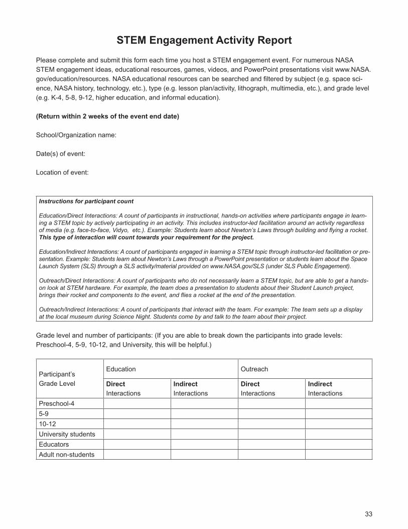
Please complete and submit this form each time you host a STEM engagement event. For numerous NASA STEM engagement ideas, educational resources, games, videos, and PowerPoint presentations visit www.NASA.gov/education/resources.NASAeducationalresourcescanbesearchedandfilteredbysubject(e.g.spacesci-ence, NASA history, technology, etc.), type (e.g. lesson plan/activity, lithograph, multimedia, etc.), and grade level (e.g. K-4, 5-8, 9-12, higher education, and informal education).
(Return within 2 weeks of the event end date)
School/Organizationname:
Date(s) of event:
Location of event:
Instructions for participant count
Education/Direct Interactions: A count of participants in instructional, hands-on activities where participants engage in learn-ing a STEM topic by actively participating in an activity. This includes instructor-led facilitation around an activity regardless of media (e.g. face-to-face, Vidyo, etc.). Example: Students learn about Newton’s Laws through building and flying a rocket. This type of interaction will count towards your requirement for the project.
Education/Indirect Interactions: A count of participants engaged in learning a STEM topic through instructor-led facilitation or pre-sentation. Example: Students learn about Newton’s Laws through a PowerPoint presentation or students learn about the Space Launch System (SLS) through a SLS activity/material provided on www.NASA.gov/SLS (under SLS Public Engagement).
Outreach/Direct Interactions: A count of participants who do not necessarily learn a STEM topic, but are able to get a hands-on look at STEM hardware. For example, the team does a presentation to students about their Student Launch project, brings their rocket and components to the event, and flies a rocket at the end of the presentation.
Outreach/Indirect Interactions: A count of participants that interact with the team. For example: The team sets up a display at the local museum during Science Night. Students come by and talk to the team about their project.
Gradelevelandnumberofparticipants:(Ifyouareabletobreakdowntheparticipantsintogradelevels:Preschool-4, 5-9, 10-12, and University, this will be helpful.)
Participant’sGrade Level
Education Outreach
Direct Interactions
Indirect Interactions
Direct Interactions
Indirect Interactions
Preschool-45-910-12University studentsEducatorsAdult non-students
34
Aretheparticipantswithaspecialgroup/organization(i.e.GirlScouts,4-H,school)?YN
Ifyes,whatgroup/organization?
Brieflydescribeyouractivitieswiththisgroup.
Howdoesthisactivityconnecttoyourteam’soverallmission,goals,objectives,andNASA’smissionstatement?
Didyouconductanevaluation?Ifso,whatweretheresults?
Describe the comprehensive feedback received.
Safety
36
High Power Rocket Safety CodeProvided by the National Association of Rocketry
1. Certification.Iwillonlyflyhighpowerrocketsorpossesshighpowerrocketmotorsthatarewithinthescopeofmyusercertificationandrequiredlicensing.
2. Materials.Iwilluseonlylightweightmaterialssuchaspaper,wood,rubber,plastic,fiberglass,orwhennecessary ductile metal, for the construction of my rocket.
3. Motors.Iwilluseonlycertified,commerciallymaderocketmotors,andwillnottamperwiththesemotorsorusethemforanypurposesexceptthoserecommendedbythemanufacturer.Iwillnotallowsmoking,openflames,norheatsourceswithin25feetofthesemotors.
4. Ignition System.Iwilllaunchmyrocketswithanelectricallaunchsystem,andwithelectricalmotorigniters that are installed in the motor only after my rocket is at the launch pad or in a designated preppingarea. My launch system will have a safety interlock that is in series with the launch switch that is notinstalled until my rocket is ready for launch, and will use a launch switch that returns to the “off” positionwhenreleased.Thefunctionofonboardenergeticsandfiringcircuitswillbeinhibitedexceptwhenmyrocket is in the launching position.
5. Misfires.IfmyrocketdoesnotlaunchwhenIpressthebuttonofmyelectricallaunchsystem,Iwillremovethelauncher’ssafetyinterlockordisconnectitsbattery,andwillwait60secondsafterthelastlaunch attempt before allowing anyone to approach the rocket.
6. Launch Safety.Iwillusea5-secondcountdownbeforelaunch.Iwillensurethatameansisavailabletowarnparticipantsandspectatorsintheeventofaproblem.Iwillensurethatnopersonisclosertothe launch pad than allowed by the accompanying Minimum Distance Table. When arming onboardenergeticsandfiringcircuitsIwillensurethatnopersonisatthepadexceptsafetypersonnelandthoserequiredforarminganddisarmingoperations.Iwillcheckthestabilityofmyrocketbeforeflightandwillnotflyitifitcannotbedeterminedtobestable.WhenconductingasimultaneouslaunchofmorethanonehighpowerrocketIwillobservetheadditionalrequirementsofNFPA1127.
7. Launcher.Iwilllaunchmyrocketfromastabledevicethatprovidesrigidguidanceuntiltherockethasattainedaspeedthatensuresastableflight,andthatispointedtowithin20degreesofvertical.Ifthewindspeedexceeds5milesperhourIwillusealauncherlengththatpermitstherockettoattainasafevelocitybeforeseparationfromthelauncher.Iwilluseablastdeflectortopreventthemotor’sexhaustfromhittingtheground.Iwillensurethatdrygrassisclearedaroundeachlaunchpadinaccordancewith the accompanying Minimum Distance table, and will increase this distance by a factor of 1.5 andclear that area of all combustible material if the rocket motor being launched uses titanium sponge inthe propellant.
8. Size. My rocket will not contain any combination of motors that total more than 40,960 N-sec (9208pound-seconds)oftotalimpulse.Myrocketwillnotweighmoreatliftoffthanone-thirdofthecertifiedaverage thrust of the high power rocket motor(s) intended to be ignited at launch.
37
9. FlightSafety.Iwillnotlaunchmyrocketattargets,intoclouds,nearairplanes,norontrajectoriesthattake it directly over the heads of spectators or beyond the boundaries of the launch site, and will not putanyflammableorexplosivepayloadinmyrocket.Iwillnotlaunchmyrocketsifwindspeedsexceed20milesperhour.IwillcomplywithFederalAviationAdministrationairspaceregulationswhenflying,and will ensure that my rocket will not exceed any applicable altitude limit in effect at that launch site.
10. Launch Site.Iwilllaunchmyrocketoutdoors,inanopenareawheretrees,powerlines,occupiedbuildings,andpersonsnotinvolvedinthelaunchdonotpresentahazard,andthatisatleastaslargeonitssmallestdimensionasone-halfofthemaximumaltitudetowhichrocketsareallowedtobeflownatthat site or 1500 feet, whichever is greater, or 1000 feet for rockets with a combined total impulse of lessthan 160 N-sec, a total liftoff weight of less than 1500 grams, and a maximum expected altitude of lessthan 610 meters (2000 feet).
11. Launcher Location. My launcher will be 1500 feet from any occupied building or from any public highwayonwhichtrafficflowexceeds10vehiclesperhour,notincludingtrafficflowrelatedtothelaunch.Itwillalso be no closer than the appropriate Minimum Personnel Distance from the accompanying table fromany boundary of the launch site.
12. Recovery System.Iwillusearecoverysystemsuchasaparachuteinmyrocketsothatallpartsofmyrocketreturnsafelyandundamagedandcanbeflownagain,andIwilluseonlyflame-resistantorfireproofrecoverysystemwaddinginmyrocket.
13. Recovery Safety.Iwillnotattempttorecovermyrocketfrompowerlines,talltrees,orotherdangerousplaces,flyitunderconditionswhereitislikelytorecoverinspectatorareasoroutsidethelaunchsite,nor attempt to catch it as it approaches the ground.
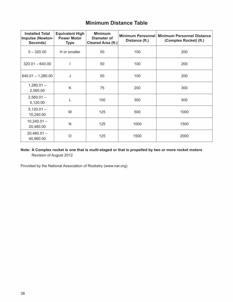
38
Minimum Distance Table
Installed Total Impulse (Newton-
Seconds)
Equivalent High Power Motor
Type
Minimum Diameter of
Cleared Area (ft.)
Minimum Personnel Distance (ft.)
Minimum Personnel Distance (Complex Rocket) (ft.)
0 – 320.00 H or smaller 50 100 200
320.01 – 640.00 I 50 100 200
640.01 – 1,280.00 J 50 100 200
1,280.01 – 2,560.00
K 75 200 300
2,560.01 – 5,120.00
L 100 300 500
5,120.01 – 10,240.00
M 125 500 1000
10,240.01 – 20,480.00
N 125 1000 1500
20,480.01 – 40,960.00
O 125 1500 2000
Note: A Complex rocket is one that is multi-staged or that is propelled by two or more rocket motors Revision of August 2012
Provided by the National Association of Rocketry (www.nar.org)
Awards

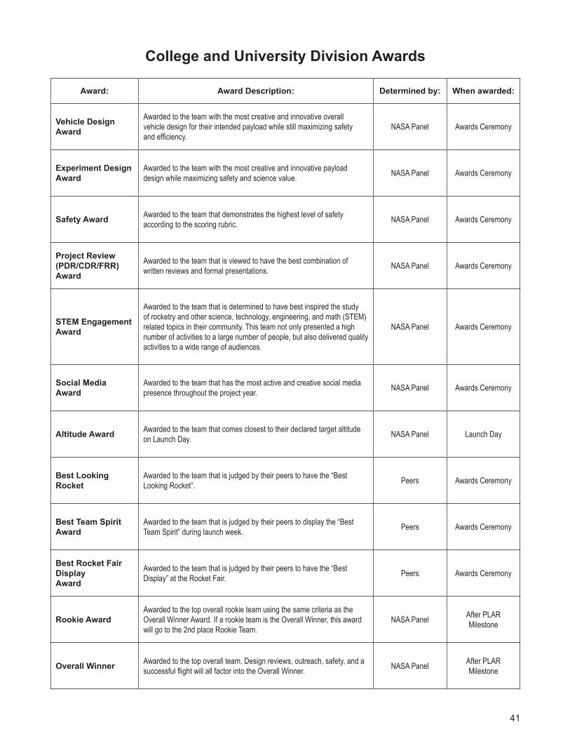
41
College and University Division Awards
Award: Award Description: Determined by: When awarded:
Vehicle Design Award
Awarded to the team with the most creative and innovative overall vehicle design for their intended payload while still maximizing safety and efficiency.
NASA Panel Awards Ceremony
Experiment DesignAward
Awarded to the team with the most creative and innovative payload design while maximizing safety and science value.
NASA Panel Awards Ceremony
Safety Award Awarded to the team that demonstrates the highest level of safety according to the scoring rubric.
NASA Panel Awards Ceremony
Project Review(PDR/CDR/FRR)Award
Awarded to the team that is viewed to have the best combination of written reviews and formal presentations.
NASA Panel Awards Ceremony
STEM Engagement Award
Awarded to the team that is determined to have best inspired the study of rocketry and other science, technology, engineering, and math (STEM) related topics in their community. This team not only presented a high number of activities to a large number of people, but also delivered quality activities to a wide range of audiences.
NASA Panel Awards Ceremony
Social Media Award
Awarded to the team that has the most active and creative social media presence throughout the project year.
NASA Panel Awards Ceremony
Altitude Award Awarded to the team that comes closest to their declared target altitude on Launch Day.
NASA Panel Launch Day
Best Looking Rocket
Awarded to the team that is judged by their peers to have the “Best Looking Rocket”.
Peers Awards Ceremony
Best Team Spirit Award
Awarded to the team that is judged by their peers to display the “Best Team Spirit” during launch week.
Peers Awards Ceremony
BestRocketFairDisplayAward
Awarded to the team that is judged by their peers to have the “Best Display” at the Rocket Fair.
Peers Awards Ceremony
Rookie AwardAwarded to the top overall rookie team using the same criteria as the Overall Winner Award. If a rookie team is the Overall Winner, this award will go to the 2nd place Rookie Team.
NASA PanelAfter PLAR Milestone
Overall Winner Awarded to the top overall team. Design reviews, outreach, safety, and a successful flight will all factor into the Overall Winner.
NASA PanelAfter PLAR Milestone
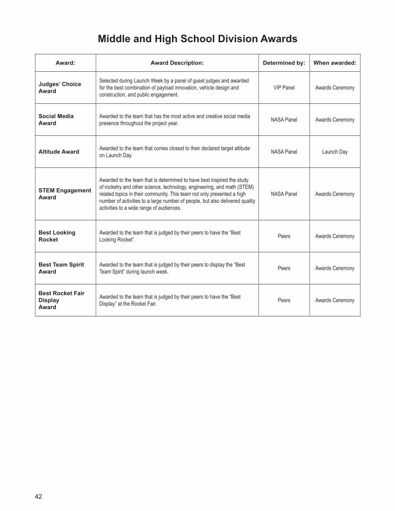
42
Middle and High School Division Awards
Award: Award Description: Determined by: When awarded:
Judges’ Choice Award
Selected during Launch Week by a panel of guest judges and awarded for the best combination of payload innovation, vehicle design and construction, and public engagement.
VIP Panel Awards Ceremony
Social Media Award
Awarded to the team that has the most active and creative social media presence throughout the project year.
NASA Panel Awards Ceremony
Altitude Award Awarded to the team that comes closest to their declared target altitude on Launch Day.
NASA Panel Launch Day
STEM Engagement Award
Awarded to the team that is determined to have best inspired the study of rocketry and other science, technology, engineering, and math (STEM) related topics in their community. This team not only presented a high number of activities to a large number of people, but also delivered quality activities to a wide range of audiences.
NASA Panel Awards Ceremony
Best Looking Rocket
Awarded to the team that is judged by their peers to have the “Best Looking Rocket”.
Peers Awards Ceremony
Best Team Spirit Award
Awarded to the team that is judged by their peers to display the “Best Team Spirit” during launch week.
Peers Awards Ceremony
BestRocketFairDisplayAward
Awarded to the team that is judged by their peers to have the “Best Display” at the Rocket Fair.
Peers Awards Ceremony


National Aeronautics and Space Administration
George C. Marshall Space Flight CenterHuntsville, AL 35812www.nasa.gov/marshall
www.nasa.gov
NP-2018-08-072-MSFCG-397154