Embed Size (px)
Citation preview
NAS Document NO. 20090401 Rev.10/2016 1 North American Signal Copyright ©2005 NAS
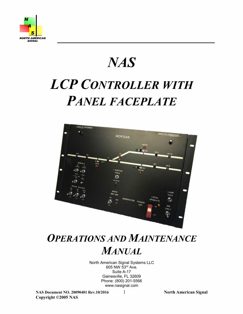
NAS
LCP CONTROLLER WITH PANEL FACEPLATE
OPERATIONS AND MAINTENANCE
MANUAL North American Signal Systems LLC
605 NW 53rd Ave. Suite A-17
Gainesville, FL 32609 Phone: (800) 201-5566
www.nasignal.com

NAS Document NO. 20090401 Rev.10/2016 2 North American Signal Copyright ©2005 NAS
Introduction ......................................................................................................... 3 System Components .......................................................................................... 4
LCP Controller ................................................................................................... 4 Inputs-Outputs ................................................................................................... 4 Input Output Faceplate ...................................................................................... 4 Custom Enclosure ............................................................................................. 4 LCP Controller Module Type II .......................................................................... 5
Programming and Set Up ................................................................................... 7 Loading Executive Program .............................................................................. 7
Installation ........................................................................................................... 8 Type II Controller Module .................................................................................. 8 Type II Module Switch Settings ......................................................................... 9
USS Microlok II & CIO-1A ............................................................................ 10 GETS VHLC, CIO-CLA & CIO-2A ................................................................ 10
System Checks ............................................................................................... 11 Initial Site Set Up ......................................................................................... 11
LCP Controller Ordering Information .............................................................. 12 Maintenance and Troubleshooting .................................................................. 13
Troubleshooting Checklist ............................................................................... 13 Specifications: LCP Controller ........................................................................ 14 Terms and Conditions of Sale ......................................................................... 15 Appendix ........................................................................................................... 18
LCP Typical Drawing Type II Module MicroLok II ........................................ 18 LCP Typical Drawing Type II Module VHLC ................................................ 18 LCP Typical Drawing Type II Module ELECTROLOGIXS CIO-1A ............... 18 LCP Typical Drawing Type II Module ELECTROLOGIXS CIO-2A ............... 18 LCP Typical Drawing Type II Module ELECTROLOGIXS CIO-CLA ............ 18

NAS Document NO. 20090401 Rev.10/2016 3 North American Signal Copyright ©2005 NAS
Introduction The NAS LCP controller with panel faceplate provides automated control of local control panels utilized for wayside control applications. The module is designed to provide discrete control of panel functions using serial commands provided by solid-state interlocking controllers such as the GETS VHLC unit or the USS Microlok II systems. Serial protocol communications to other devices can be provided based on customer request. Controllers can be interfaced to custom or generic faceplates designed and manufactured by North American Signal. The controller and faceplates make up a single self-contained aluminum enclosure that can be shelf wall or rack mounted in an instrument house. The LCP controller comes equipped with onboard isolated power supply along with isolated 232E, 422 or 20MA loop for direct isolated interface to a controller’s communication port. The unit is expandable to accommodate up to 128 inputs and 128 outputs in a single module. Inputs and outputs are blocked in groups of 16 to easily handle bit mapping of the discrete devices. The on-board processor provides additional features such as self-diagnostic indicators and custom functions allowing the user more flexibility in the design of the local control interface. Serial protocols are easily changed with the selection of onboard rocker switches allowing one device to be used for all of your remote control applications. Faceplates used for discrete control and indications are manufactured per customer specification. Location details can be displayed on photo etched or silk screen panels. Various types of indicators and controls such as LEDs and pushbutton switches are included with a turnkey solution offered by NAS. Have a custom application? Not a problem for the staff at North American Signal. We will find a way to adapt the equipment to meet your requirements.

NAS Document NO. 20090401 Rev.10/2016 4 North American Signal Copyright ©2005 NAS
System Components The LCP Controller is a single board stand-alone controller with custom enclosure and faceplate designed to provide discrete input output interface using serial communication from a solid-state controller unit. Ease of installation and setup allow the user to be operational with minimal procedures. LCP Controller
The LCP controller is equipped with on-board process control and input output interface to operate up to 128 separate inputs and 128 separate outputs. Equipped with Isolated Power supply allows the unit to be controlled using a wide range of input voltage ranging from 9-36volts DC.
Inputs-Outputs
Input output interface provides full isolation using opto-isolated inputs and output drivers. Two types of I/O interface connectors are available for panel interface. Type I utilizes ribbon cable connectors to onboard couplers providing a secure, reliable connection. Inputs and outputs are provided in blocks of 16 each, 32 total per connector. I/O expansion board mounts directly to the back of the LCP faceplate for ease of wiring. Type II utilizes 64 Pin cable couplers making interface directly compatible with a CLCP type unit.
Input Output Faceplate
The LCP controller can be furnished with custom or generic faceplate panels for wayside control functions. I/O connectors are fanned out to the NAS panel interface modules for direct wiring of LEDs and switches. The interface module is a passive device and allows for ease of termination of wiring from the panel. Faceplates are designed based on customer specification. Switches, lamps or LEDs are provided in various configurations to accommodate customer requirements.
Custom Enclosure
Panel electronics and faceplate are mounted in a custom rack or shelf mountable aluminum enclosure.

NAS Document NO. 20090401 Rev.10/2016 5 North American Signal Copyright ©2005 NAS
LCP Controller Module Type II The Type II panel interface module uses 64 pin plug couplers in lieu of ribbon style connectors to interface to discrete I/O on the panel faceplate. Functionality is identical with the ability to sink or source I/O with dipswitch settings. Interface to solid-state controllers is through the DB-9 serial ports located on the I/O board. Serial communications using RS232 signal levels or current loop are available. Interface details are located in the Appendix of this manual.
DB 9

NAS Document NO. 20090401 Rev.10/2016 6 North American Signal Copyright ©2005 NAS
Type II Module
NAS Document NO. 20090401 Rev.10/2016 7 North American Signal Copyright ©2005 NAS
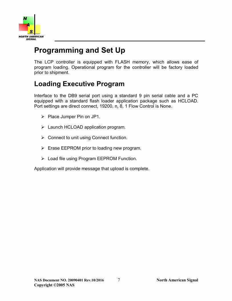
Programming and Set Up The LCP controller is equipped with FLASH memory, which allows ease of program loading. Operational program for the controller will be factory loaded prior to shipment.
Loading Executive Program Interface to the DB9 serial port using a standard 9 pin serial cable and a PC equipped with a standard flash loader application package such as HCLOAD. Port settings are direct connect, 19200, n, 8, 1 Flow Control is None. Place Jumper Pin on JP1.
Launch HCLOAD application program.
Connect to unit using Connect function.
Erase EEPROM prior to loading new program.
Load file using Program EEPROM Function.
Application will provide message that upload is complete.
NAS Document NO. 20090401 Rev.10/2016 8 North American Signal Copyright ©2005 NAS
Installation
Type II Controller Module Refer to system drawings located in the Appendix of this manual for detail interface of the LCP controller and I/O module for the specific type controller interface. Refer to Switch and Jumper pin settings to insure proper configuration for the application. Install power to unit interfacing 9-36 Volts DC to TB3 Wago Terminal located on the LCP I/O Module. For MicroLok II, interface serial cable provided to DB-9 serial connector located on the LCP controller board P6. For interface to a GETS VHLC unit using a current loop adaptor board, interface cable provided to DB9 P1 on the module. Cable provided will have appropriate plug to interface to the CLA module. Turn Power switch ON.

NAS Document NO. 20090401 Rev.10/2016 9 North American Signal Copyright ©2005 NAS
Type II Module Switch Settings The LCP controller module is equipped with an 8-position rocker switch (Switch 2) and 7 jumper pins located on the controller board. Switch settings should be set as follows:
Switch 2 – Rocker switch down to left is in open position. Switch is identified with open and closed positions.
Switch 2

NAS Document NO. 20090401 Rev.10/2016 10 North American Signal Copyright ©2005 NAS
USS Microlok II, CIO-1A & CIO-2A POS 1 and 2: Sets Genysis Address- Pos 1 Closed, Pos 2 Open POS 3 -5: Not Used POS 6: Open common anode LED’s, Closed Common Cathode LED’s Pos 6 CLOSED POS 7: Open Normally Open Pushbuttons Common Tied to +5V, Closed Normally Closed Push buttons Common Tied to +5V Pos 7 Open POS 8: Closed GETS Emulation, Open Genysis Emulation Pos 8 Open P8- Factory Program Enable – Open JP1 Pull Up Level (H/L) POS H JP2 – Pos RS232, Pos Current Loop POS RS232 GETS VHLC & CIO-CLA POS 1 and 2: Sets Genysis Address- Pos 1 Open, Pos 2 Open POS 3 -5: Not Used POS 6: Open common anode LED’s, Closed Common Cathode LED’s Pos 6 CLOSED POS 7: Open Normally Open Pushbuttons Common Tied to Common, Closed Normally Closed Push buttons Common Tied to Common Pos 7 Open POS 8: Closed GETS Emulation, Open Genysis Emulation Pos 8 Closed P8- Factory Program Enable – Open JP1 Pull Up Level (H/L) POS H JP2 – Pos RS232, Pos Current Loop POS C/L
NAS Document NO. 20090401 Rev.10/2016 11 North American Signal Copyright ©2005 NAS
System Checks Initial Site Set Up When design, module configuration, and interface wiring to external circuitry are complete, the LCP controller module can undergo operational testing for the programmed application. The system should be tested to insure the function it was designed to perform is operational. Bit mapping is a function of the solid-state controller non-vital application program. A copy of the bit assignment should be used to verify proper input output functions. Verify that all battery connections are the proper polarity in accordance with
details shown on Terminal Board Configurations. Turn on power switch to the module. Insure Power LED located above the ON/OFF switch is illuminated. Verify that module LED communication is operating in accordance with the
details outlined in the Hardware Description section for the module. Verify Inputs and Outputs are operating based on configured application.

NAS Document NO. 20090401 Rev.10/2016 12 North American Signal Copyright ©2005 NAS
LCP Controller Ordering Information The LCP Controller can be equipped with or without panel faceplate. Ordering references for system configurations are listed in the table below. Item Unit Catalog Ref No.
NAS LCP Controller Module with Power Supply
EA
NAS Cat No. NAS-0400-118-256
CIO-2A CABLE ELECTROLOGIXS EA NAS-CBL-ELECIO-2A-5 Serial Cable MLOKII EA NAS-CBL-232-5 Current Loop Cable VHLC EA NAS-CBL-CL-5 CIO-1A CABLE ELECTROLOGIXS EA NAS-CBL-ELECIO-1A-5 CIO-CLA CABLE ELECTROLOGIXS EA NAS-CBL-ELECIO-CLA-5 Faceplates Call Factory

NAS Document NO. 20090401 Rev.10/2016 13 North American Signal Copyright ©2005 NAS
Maintenance and Troubleshooting The LCP Controller system is a robust hardware package designed to operate in the harshest environments. The module has onboard process control and visual LED indicators. At North American Signal, we try very hard to keep things simple, which includes diagnosing a problem with the unit if it is not functioning correctly. As with any troubleshooting procedure, the first order of business is to assess what the reported problems are and eliminate potential causes. Visual inspection of the LED indicators on the module is a quick, easy way to assess if the failure is hardware related. Troubleshooting Checklist Chassis Power lights not illuminated: Check input voltage on battery
voltage input terminals 7 and 8 to determine if between 9-36 volts DC. Possible DC-DC converter failure on motherboard.
Health LED not flashing at one and one half second rate on module:
Possible processor failure. Insure power is within specification. Input or Output not functioning: Check connections and voltage on
appropriate Terminal on Panel Interface Module. If present and not functioning, faulty input or output is possible - replace module.
Unit not communicating to Controller: If serial communication is lost
between the LCP controller and the host device all LEDs will flash once per second. Bad serial cable, Host Device failure, Controller failure.

NAS Document NO. 20090401 Rev.10/2016 14 North American Signal Copyright ©2005 NAS
Specifications: LCP Controller Physical: Module: 11” L X 7”W Environment: -40 to +71 Degrees C Inputs: 128 Isolated Digital Inputs 5V DC 3000 volt isolation Outputs: 128 isolated Outputs 5 Volts DC LEDs Power: DC-DC Converter Operating Voltage 9-36V DC, Isolated Ground Serial Ports: DB9 Serial Female on Controller Card Terminals: WAGO 8 way plug in connector Wire Size 14 AWG—22AWG

NAS Document NO. 20090401 Rev.10/2016 15 North American Signal Copyright ©2005 NAS
Terms and Conditions of Sale General Our sale to you will be solely upon the terms and conditions set forth herein. They supersede and reject any conflicting terms and conditions of yours. Exceptions to any of our terms and conditions must be contained in a written or typed statement received from you. We shall not be deemed to have waived any of our terms and conditions or to have assented to any modification or alteration of such terms and conditions unless such waiver or assent is in writing and signed by an authorized officer. Prices Unless otherwise noted on the face thereof, prices are net F.O.B our factory and firm for thirty (30) days. The amount of any applicable present or future tax upon the production, sale, shipment or use of goods ordered or sold will be added to billing unless you provide us with an appropriate exemption certificate. Warranty North American Signal (NAS) warrants it products and systems against defects in material and workmanship for a period of One (1) Year from date of shipment. Sellers entire warranty obligation is limited to repairing or replacing any equipment which is returned within the warranty period and which the seller finds to be so defective. The integrity of NAS products and systems cannot be finally checked until all devices and circuits are connected to form a complete system or an effective portion thereof. Once accepted, NAS’s warranty will be limited to parts that have been fully paid for. Return of equipment to Seller is at Buyers risk, and expense. Equipment returned to seller must be clearly identified and instructions must be furnished for reshipment to Buyer of the repaired or replaced device. Equipment will be returned to the NAS plant of original manufacture. Adjustments will not be allowed for products or components which have been subject to abuse, alteration, improper handling or installation, or which have not been operated in accordance with the seller’s instructions. Cancellation of Orders A cancellation charge will be established on a percentage of completion basis. Restocking The seller on equipment returned to NAS for credit/or exchange will charge a restocking fee of 30%.

NAS Document NO. 20090401 Rev.10/2016 16 North American Signal Copyright ©2005 NAS
Credit and Payment Unless otherwise noted, terms are net 30 days. We may decline to deliver except for cash, or stop goods in transit, whenever for any reason doubt as to your financial responsibility develops. Pro rata payments shall become due with partial shipments. Where you are responsible for delay in shipment of any goods, the date of completion of goods may be treated as the shipment date for purposes of payment. On late payments, the contract price shall be increased by 1 ½ percent per month on the unpaid balance but not to exceed the maximum permitted by law. Out of Warranty NAS will repair or replace equipment that is termed out of warranty under the following terms: The customer shall return equipment to NAS at customer’s expense. When the equipment is repaired and returned, customer shall be invoiced for the
equipment based on total cost of labor and materials used for repair, test and inspection.
If it is determined by NAS that the repair cost will exceed 50% of the cost of new, NAS will notify the customer prior to the repair being made for direction. Shipping Unless you specify otherwise, goods will be boxed or crated, as we deem proper for protection against normal handling. Routing and manner of shipment will be at our discretion and may be insured at your expense. Delivery of goods to the initial carrier will constitute delivery to you and all goods will be shipped at your risk. A claim for loss or damage in transit must be entered with the carrier and prosecuted by you. Proprietary Data Neither you nor any other person shall have any right to or have control over any engineering or production prints, drawings, or technical data which we in our sole discretion may consider proprietary to ourselves. Software Terms The following terms apply to products or systems that contain software. Subject to the terms and conditions hereof NAS grants you a nonexclusive
nontransferable license to use the software at the designated site listed hereof. This license extends wholly to your internal use of the software. The software shall be used only on the platform assigned.
If the platform is a single personal computer the software may be used by a single user on a single PC system
If the platform is a local area network the software may be used only on a single local area network at the designated site and in accordance with the number of users designated in the order for the system or as licenses permit.

NAS Document NO. 20090401 Rev.10/2016 17 North American Signal Copyright ©2005 NAS
If the platform is an embedded device or system, the software may only be used
for that single embedded device or system. Except with regard to embedded software you may copy the software on the
platform identified and make a backup copy of the software for archival purposes. Except for the license to use the software as expressly set forth in this agreement
all rights, titles and interest in the software shall be retained by NAS. You do not own any copies of the software or any portion thereof. Ownership of the software is retained by NAS. You will not or allow any third party to create a derivative of the work or modify any of the software without the approval of NAS. You will not allow any third party to reverse assemble, decompile, or otherwise reverse engineer all or any portion of the any product or system produced by NAS.
Sales and Service: The team at North American Signal is available to help you. Please contact our Customer Service Department for inquiries or service repairs. Thanks for being our customer! North American Signal Systems LLC Sales and Service Office 605 NW 53rd Ave. Suite A-17 Gainesville, FL 32609 Phone (352)376-8341 or (800) 201-5566 Website address www.nasignal.com Email [email protected]

NAS Document NO. 20090401 Rev.10/2016 18 North American Signal Copyright ©2005 NAS
Appendix
Unit Diagram Typical LCP Controller
Configurations LCP Typical Drawing Type II Module MicroLok II LCP Typical Drawing Type II Module VHLC LCP Typical Drawing Type II Module ELECTROLOGIXS CIO-1A LCP Typical Drawing Type II Module ELECTROLOGIXS CIO-2A LCP Typical Drawing Type II Module ELECTROLOGIXS CIO-CLA