Embed Size (px)
Citation preview
.
NARROW GROOVE WELDING GAS DIFFUSER
ASSEMBLY AND WELDING TORCH
INVENTOR: Stephen J. Rooney
L
DISCXAIMER
This report was.prepared as an account of work sponsoredby an agency of the United States Government. Neitherthe United States Government nor any agency thereof, norany of their employees, make any warranty, express orimplied, or assumes any legal liability or responsibility forthe accuracy, completeness, or usefulness of anyinformation, apparatus, product, or process disclosed, orrepresents that its use would not infringe privately ownedrights. Reference herein to any specific commercialproduct, process, or service by trade name, trademark,manufacturer, or otherwise does not necessarily constituteor imply its endorsement, recommendation, or favoring bythe United States Government or any agency thereof. Theviews and opinions of authors expressed herein do notnecessarily state or reflect those of the United StatesGovernment or any agency thereof.

DISCLAIMER
Portions of this document may be illegiblein electronic image products. Images areproduced from the best available originaldocument.
r., ,“
1
NARROW GROOVE WELDING GAS DIFFUSER
ASSEMBLY AND WELDING TORCH
CONTRACTUAL ORIGIN OF THE INVENTION
The United States Government has rights
a contract with the Department of Energy.
BACKGROUND OF THE INVENTION
1. Field of the Invention
in this invention pursuant to
10 The present invention generally relates to automatic Gas Tungsten Arc
Welding (AGTAW or GTAW) and, more particularly, to narrow groove
welding torches for such welding, and to gas diffusers thereof.
2. Related Art
The AGTAW process uses welding equipment which, for a given set of
welding parameters (current, voltage, travel speed and the like) performs the
weld with minimal adjustments or corrections by the welding operator. As
discussed below, particular problems are presented in providing a weld joint
in a narrow groove in thick plates or heavy wall pipes.
I
. ,“
2
Typically, a weld prep is determined by a joint geometry which
requires the least amount of welding and therefore, reduces distortion and
material stresses. However, it is
provide good accessibility for the
also necessary
welding torch.
heavy wail pipes requires a weld joint design which
or at least the electrode thereof, to be placed in the
that the joint geometry
Welding thick plates or
allows the welding torch,
joint and the work angle
of the torch adjusted into the side wall to assure a good weld tie-in as a
series of weld beads are deposited layer by layer until the joint is filled.
One technique for welding thick plates requires the adjacent surfaces
10 to be machined or otherwise prepared in advance in order to provide a “V”
notch having a large volume to accommodate the welding torch.
Unfortunately, while more maneuvering room is provided, multiple (24-1 50)
weld beads per layer are required to fill the large volume created for the
1s s~~ i n.+
welding torch. Therefore, the welding process requireg.f’additio al setup and
machining time, preparation, filler material and shielding gas. In addition, the
multiple bead layers are subject to distortion and internal stresses that result
in decreased weld quality.
In an effort to reduce welding time and cost, a joint design which
requires a minimal amount of welding is preferable. Narrow groove welding
20 is a process wherein successive single bead weld layers are applied directly
on top of one another in a narrow groove or joint, thus requiring a minimal
3
.’.
amount of root opening on the order of 0.250 inches and a 0° side wall.
Briefly considering the difficulties created by the geometry and
restrictiveness of the narrow grooves of the type just described, the welding
torch or associated hardware must be modified to weld the entire joint from
the surface since such a joint design provides insufficient room to angle
maneuver the torch in the joint. In addition, it is difficult to obtain the
or
amount of shield gas in the weld joint necessary to protect the molten weld
pool and electrode from atmospheric contamination. Moreover, in an
approach where a long bare electrode is inserted into the groove and an
10 associated diffuser is placed outside of the weld joint, there can be problems
with the amount of Argon shield gas used to protect the weld pool and
electrode. For example; in a confined area or work space, the shield gas
rapidly replaces the oxygen available to the welding operator, thereby
creating a safety concern. More generally, the high volume of shield gas
required also adds to the cost of the weld.
SUMMARY OF THE INVENTION
According to the invention, there is provided a diffuser assembly for
narrow groove welding, as well as a welding torch assembly utilizing the
20 diffuser assembly. An advantage to the invention is that the diffuser
assembly can be used with any conventional or commercially available
.’.
4
automatic gas tungsten arc welding torch.
In accordance with a first aspect of the invention, a diffuser assembly
is provided for narrow groove welding using an automatic gas tungsten arc
welding torch including a tungsten electrode, the diffuser assembly
comprising:
a manifold adapted for adjustable mounting on the welding torch, said
manifold including a central opening for receiving the welding torch, a shield
gas inlet, and laterally extending manifold sections in communication with
said gas inlet, the manifold sections each having a gas passage therein such
10 that shield gas supplied to the inlet passes to the gas passages of the
manifold sections; and
first and second tapered diffusers respectively connected to the
manifold sections of the manifold in fluid communication with the gas
passages thereof and extending, in use, downwardly along the torch
electrode on opposite sides thereof so as to release shield gas along the
length of the electrode and at the distal tip of the electrode, the diffusers
being of a transverse width which is less than that of the manifold sections
and which is on the order of the thickness of the electrode so that the
diffusers connected to the manifold can, in use, extend into a narrow
20 welding groove before and after the electrode in the direction of the weld
operation.
<
I
. .
J
Preferably, the diffuser sections each have a shape comprising a right
triangle with a right angle portion disposed adjacent to the central opening.
In accordance with a second aspect of the invention, a torch assembly
is provided for narrow groove welding, the torch assembly comprising:
a conventional automatic gas tungsten arc torch comprising torch
body, and an adjustable electrode connected to the torch body and
positioned to extend into a narrow welding’groove, the electrode having a
distal tip end; and
a diffuser assembly mounted on the torch, the diffuser assembly
10 comprising a manifold having a shield gas inlet, and first and second gas
passages therein connected to the inlet; and first and second tapered
diffusers respectively connected to said first and second gas passages of
said manifold, and disposed before and after said electrode in the direction
the weld operation, the diffusers tapering down along the electrode to
area near the tip end of the electrode so as to release shield gas along
an
the
of
length of the electrode and in the area of the tip end, and the diffusers being
of a transverse thickness on the order of that of the electrode so as to enable
the diffusers to extend into a narrow welding groove before and after the
electrode.
20 Since, as indicated above, the diffusers of the invention are thin
enough to be placed in a weld joint wherein they are disposed on opposite
.“.
6
sides of, i.e., before and after, the welding electrode, the invention can be
used with a very narrow, steep welding groove. For example, with a specific
implementation of the invention, a narrow groove joint with a 10 side wall
and a 0.250 inch root opening , or with a 0° side wall and 0.3125 inch root
opening, can be welded to a depth of 4.00 inches. In addition, by placing
the diffusers into the weld joint, the amount of shield gas necessary to
protect the weld pool is greatly reduced.
Further features and advantages of the present invention will be set
forth in, or apparent from, the detailed description of preferred embodiments
10 thereof which follows.
BRIEF DESCRIPTION OF THE DRAWINGS
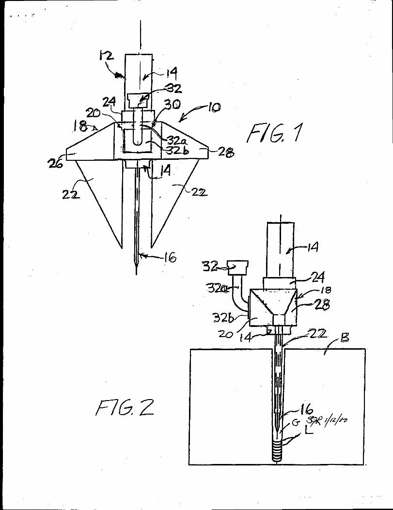
Figure 1 shows a front view of a torch assembly including a diffuser
assembly in accordance with a preferred embodiment of the invention; and
Figure 2 shows a side view of the torch assembly of Figure 1, showing
the assembly in use in welding a narrow groove in a thick plate.
DESCRIPTION OF THE PREFERRED EMBODIMENTS
20 Referring to Figure 1, a welding torch assembly 10 includes a
conventional AGTAW or GTAW torch 12 comprising a cylindrical torch body
7
. . .
14 and an elongated electrode 16. The electrode 16 is adjustable or
repositionable with respect to the torch body 14 in order to maintain the
minimum extension of the electrode necessary to weld. The torch 12 is
mounted in a diffuser assembly 18 which basically comprises a manifold 20
and a pair of diffusers 22. The manifold 20 includes a central support
member or sleeve 24 defining a central passage in which the torch body 14.,
is received and laterally extending manifold sections 26, 28 are disposed on
opposite sides of support sleeve 24. Manifold 20 further includes a central
section 30 to which is connected a shield gas inlet 32 through an inlet pipe
10 32a mounted on a mounting plate 32b affixed to central manifold section 30.
The diffuser assembly 18 is also adjustable or repositionable on the torch
body 14 in order to enable the diffusers 22 to be retracted from a joint as
weld layers L are deposited as shown in Figure 2.
The diffusers 22 are of a triangular or tapered shape as shown in
Figure 1 and are in fluid communication with the gas passages in manifold
20 so that shield gas supplied to gas inlet 32 passes through inlet pipe 32a
to central manifold section 30 and thence to lateral sections 26 and 28 and
ultimately to diffusers 22. The sides of the diffusers 22 that face and are
parallel to the electrode 16 are open and provide for the release of the shield
20 gas along the length and distal end of the electrode 16.
Preferably, the electrode 16 comprises a tungsten electrode, while the
8
triangular-shaped diffusers 22 and manifold 20 are preferably formed from
stainless steel sheet metal.
Figure 2 shows the diffuser assembly 18 mounted on the torch body
14 in use in welding a narrow groove G in a block B. In operation, during
welding, the torch body 14, and the manifold 20, remain outside the narrow
groove G, while the electrode 16 and the triangular-shaped diffusers 22
extend into the narrow groove. The diffusers 22 are positioned in the narrow
groove such that one diffuser is behind, and one diffuser is in front of, the
electrode 16 as the latter travels through the joint. The electrode 16 is
10 positioned to reach or extend to, the bottom of the weld, and both the
electrode 16 and diffuser assembly 18 are repositioned with respect to the
weld joint depth, as necessary due to the amount of weld metal deposited.
Although the invention has been described above in relation to preferred
embodiments thereof, it will be understood by those skilled in the art that
variations and modifications can be effected in these preferred embodiments
without departing from the scope and spirit of the invention.
12
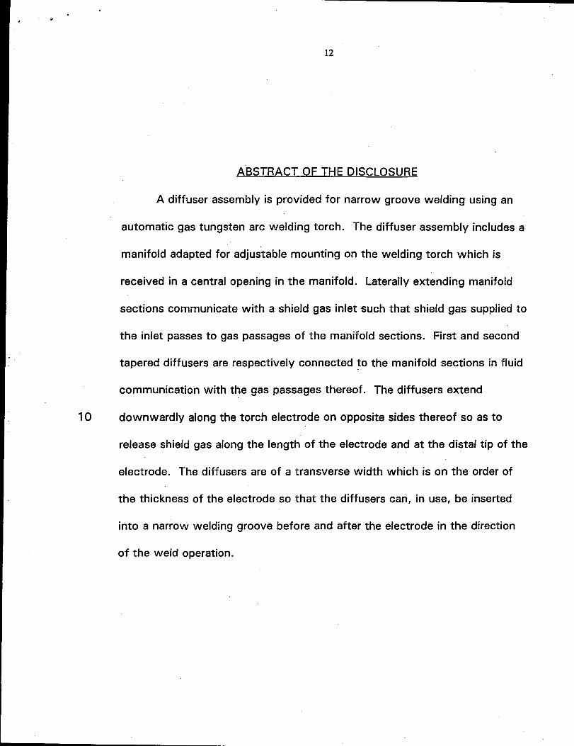
ABSTRACT OF THE DISCLOSURE
A diffuser assembly is provided for narrow groove welding using an
automatic gas tungsten arc welding torch. The diffuser assembly includes
manifold adapted for adjustable mounting on the welding torch which is
received in a central opening in the manifold. Laterally extending manifold
sections communicate
the inlet passes to gas
a
with a shield gas inlet such that shield gas supplied to
passages of the manifold sections. First and second
tapered diffusers are respectively connected to the manifold sections in fluid
communication with the gas passages thereof. The diffusers extend
10 downwardly along the torch electrode on opposite sides thereof so as to
release shie!d gas along the length of the electrode and at the distal tip of the
electrode. The diffusers are of a transverse width which is on the order of
the thickness of the electrode so that the diffusers can, in use, be inserted
into a narrow welding groove before and after the electrode in the direction
of the weld operation.
2
.7
k
—
d
- #q42
y!,
/76 z
9


![Klimaoprema katalog PPZEN DIFFUSER SLOT DIFFUSER ... Selection diagrams ... - Air velocity between two diffusers L [m] - Diffuser length B min](https://img.pdfslide.us/doc/110x75/5a9ff9c87f8b9a71178d6c6b/pdfklimaoprema-katalog-diffuser-slot-diffuser-selection-diagrams-air.jpg)