Embed Size (px)
Citation preview
III
NANOSTRUCTURED Pt/MnO2 CATALYSTS AND
THEIR PERFORMANCE FOR OXYGEN
REDUCTION REACTION IN AIR CATHODE
MICROBIAL FUEL CELL
CHAN KAR MIN
Thesis submitted in partial fulfilment of the requirements
for the award of the degree of
Bachelor of Chemical Engineering
Faculty of Chemical & Natural Resources Engineering
UNIVERSITI MALAYSIA PAHANG
JUNE 2014
©CHAN KAR MIN (2014)
VIII
ABSTRACT
Microbial fuel cells (MFCs) represent a promising sustainable clean technology for
simultaneous bioelectricity generation and wastewater treatment. Catalysts are
significant portions of the cost of microbial fuel cell cathodes. Many materials have
been tested as aqueous cathodes, but air-cathodes are needed to avoid energy demands
for water aeration. The sluggish oxygen reduction reaction (ORR) rate at air cathode
necessitates efficient electrocatalyst such as carbon supported platinum catalyst (Pt/C)
which is very costly. Manganese oxide (MnO2) was a representative metal oxide which
has been studied as a promising alternative electrocatalyst for ORR and has been tested
in air-cathode MFCs. However the single MnO2 has poor electric conductivity and low
stability. In the present work, the MnO2 catalyst has been modified by doping Pt
nanoparticle. The goal of the work was to improve the performance of the MFC with
minimum Pt loading. MnO2 and Pt nanoparticles were prepared by hydrothermal and
sol gel methods, respectively. Wet impregnation method was used to synthesize
Pt/MnO2 catalyst. The catalysts were further used as cathode catalysts in air-cathode
cubic MFCs, in which anaerobic sludge was inoculated as biocatalysts and palm
oil mill effluent (POME) was used as the substrate in the anode chamber. The as-
prepared Pt/MnO2 was characterized comprehensively through field emission scanning
electron microscope (FESEM), X-Ray diffraction (XRD), X-ray photoelectron
spectroscopy (XPS), and cyclic voltammetry (CV) where its surface morphology,
crystallinity, oxidation state and electrochemical activity were examined, respectively.
XPS revealed Mn (IV) oxidation state and Pt (0) nanoparticle metal, indicating the
presence of MnO2 and Pt. Morphology of Pt/MnO2 observed from FESEM shows that
the doping of Pt change the urchin-like structure of MnO2 into cocoon-like structure of
Pt/MnO2. The electrochemical active area of the Pt/MnO2 catalysts has been increased
from 276 to 617 m2/g with the increase in Pt loading from 0.2 to 0.8 wt%. The CV
results in O2 saturated neutral Na2SO4 solution showed that MnO2 and Pt/MnO2
catalysts could catalyze ORR with different catalytic activities. MFC with Pt/MnO2
(0.4 wt% Pt) as air cathode catalyst generates a maximum power density of 165 mW/
m3, which is higher than that of MFC with MnO2 catalyst (95 mW/m
3). There was a
slight increase in COD removal efficiency of 0.4 wt% Pt/MnO2 (84%) compared to
MnO2 and other Pt loading catalysts. The open circuit voltage (OCV) of the MFC
operated with MnO2 cathode gradually decreased during 14 days of operation, whereas
the MFC with Pt/MnO2 cathode remained almost constant throughout the operation
suggesting the higher stability of the Pt/MnO2 catalyst. Therefore, Pt/MnO2 with 0.4
wt% Pt successfully demonstrated as an efficient and low cost electrocatalyst for ORR
in air cathode MFC with higher electrochemical activity, stability and hence enhanced
performance as well as higher COD removal efficiency.
IX
ABSTRAK
Sel-sel bahan api mikrob (MFCs) merupakan teknologi yang berpotensi untuk tujuan
generasi bioelektrik dan rawatan air sisa serentak. Pemangkin adalah bahagian penting
daripada kos katod sel bahan api mikrob. Banyak bahan telah diuji sebagai katod
akueus, tetapi katod udara diperlukan bagi mengelakkan penggunaan tenaga untuk
pengudaraan air. Kadar reaksi pengurangan oksigen (ORR) yang lembap di katod udara
memerlukan pemangkin cekap seperti pemangkin platinum disokong karbon (Pt/C)
yang amat mahal. Mangan oksida (MnO2) adalah oksida logam yang telah dikaji
sebagai pemangkin alternatif untuk ORR dan telah diuji dalam MFCs katod udara.
Namun MnO2 mempunyai kekonduksian elektrik yang lemah dan kestabilan yang
rendah. Dalam karya ini, pemangkin MnO2 telah diubah suai dengan menaburkan Pt
nanopartikel. Matlamat kerja ini adalah untuk meningkatkan prestasi MFC dengan
minimum kandungan Pt. MnO2 dan Pt nanopartikel telah disediakan melalui kaedah
hidroterma dan sol gel masing-masing. Kaedah pengisitepuan basah telah digunakan
untuk mensintesis pemangkin Pt/MnO2. Pemangkin digunakan sebagai pemangkin
katod di katod udara MFCs padu, di mana enapcemar anaerobik telah disuntik sebagai
pemangkin biologi dan bahan buangan kilang minyak sawit (POME) sebagai substrat
dalam kebuk anod. Pt/MnO2 yang disediakan dicirikan secara komprehensif melalui
bidang pelepasan mikroskop imbasan elektron (FESEM), X-Ray pembelauan (XRD),
sinar-X fotoelektron spektroskopi (XPS), dan voltammetri berkitar (CV) di mana
morfologi permukaannya, penghabluran, pengoksidaan dan aktiviti elektrokimia telah
diperiksa, masing-masing. XPS mendedahkan Mn (IV) pengoksidaan dan Pt (0)
nanopartikel logam, menunjukkan kewujupan MnO2 dan Pt. Morfologi Pt/MnO2 yang
diperhatikan dari FESEM menunjukkan bahawa penaburan Pt menyebabkan perubahan
struktur urchin MnO2 kepada struktur cocoon Pt/MnO2. Kawasan aktif elektrokimia
pemangkin Pt/MnO2 telah meningkat dari 276 kepada 617 m2/g dengan peningkatan
dalam kandungan Pt 0.2-0.8 wt%. Peningkatan dalam keberkesanan peningkiran COD
diperhatikan pada 0.4 wt% Pt/MnO2. Keputusan CV menggunakan larutan neutral
Na2SO4 tepu dengan O2 menunjukkan pemangkin MnO2 dan Pt/MnO2 boleh menjadi
pemangkin ORR dengan aktiviti-aktiviti pemangkin yang berbeza. MFC dengan
Pt/MnO2 (0.4 wt% Pt) sebagai pemangkin katod udara menjana ketumpatan kuasa
maksimum 165 mW/m3, iaitu lebih tinggi daripada MFC dengan MnO2 pemangkin (95
mW/m3). Voltan litar terbuka (OCV) daripada MFC dikendalikan dengan MnO2 katod
menurun secara beransur-ansur dalam 14 hari beroperasi, manakala MFC dengan
Pt/MnO2 katod yang kekal hampir malar sepanjang operasi itu mencadangkan
kestabilan yang lebih tinggi oleh pemangkin Pt/MnO2. Oleh itu, Pt/MnO2 dengan 0.4
wt% Pt berjaya menunjukkan ia sebagai pemangkin cekap yang berkos rendah untuk
ORR di katod udara MFC dengan aktiviti elektrokimia dan kestabilan yang lebih tinggi,
justeru prestasi yang dipertingkatkan serta peningkiran COD yang lebih tinggi.
X
TABLE OF CONTENTS
SUPERVISOR’S DECLARATION ............................................................................... IV STUDENT’S DECLARATION ...................................................................................... V Dedication ....................................................................................................................... VI ACKNOWLEDGEMENT ............................................................................................. VII
ABSTRACT ................................................................................................................. VIII ABSTRAK ...................................................................................................................... IX TABLE OF CONTENTS ................................................................................................. X LIST OF FIGURES ....................................................................................................... XII LIST OF TABLES ....................................................................................................... XIV LIST OF ABBREVIATIONS ....................................................................................... XV
LIST OF ABBREVIATIONS ...................................................................................... XVI 1 INTRODUCTION .................................................................................................... 1
1.1 Chapter Overview .............................................................................................. 1 1.2 Background ........................................................................................................ 1 1.3 Problem Statement and Motivation .................................................................... 3 1.4 Objective ............................................................................................................ 5
1.5 Scope of Study ................................................................................................... 5 1.6 Significance of Study ......................................................................................... 5
1.7 Organisation of Thesis ....................................................................................... 6
2 LITERATURE REVIEW ......................................................................................... 7 2.1 Chapter Overview .............................................................................................. 7
2.2 Power Generation by Microbial Fuel Cells and Its Present Status .................... 7 2.3 Factors Influencing Microbial Fuel Cell Performance..................................... 13
2.3.1 Microbial Metabolism ............................................................................... 13 2.3.2 Types of Substrates ................................................................................... 14
2.3.3 Membrane ................................................................................................. 18 2.3.4 Electrode Materials ................................................................................... 21
2.4 Air Cathode Microbial Fuel Cells .................................................................... 24
2.4.1 Cathodic Limitations of Air Cathode Microbial Fuel Cell ....................... 25
2.4.1.1 Ohmic Losses………………………………………………………..25
2.4.1.2 Mass Transport Losses……………………………………………....26
2.4.1.3 Activation Overpotential…………………………………………….26
2.4.2 Oxygen Reduction Reaction .................................................................... .27
2.4.2.1 Platinum-based Electrocatalyst……………………………….….......28
2.4.2.2 Non-Platinum based Catalysts in Air Cathode Microbial Fuel
Cell…………………………………………………………………...31
2.4.2.2.1 Performance of Manganese Dioxide in Air Cathode Microbial
Fuel Cell………………………………………………………..33
2.4.2.2.2 Oxygen Reduction Pathway on Manganese Oxides…………....36
2.4.2.2.3 Limitation of Manganese Dioxide in Air Cathode Microbial Fuel
Cell……………………………………………………………. .37
2.4.2.2.4 Modification of Manganese Dioxide……………………….…..37
2.4 Summary .......................................................................................................... 38
3 MATERIALS AND METHODS ............................................................................ 40
3.1 Chapter Overview ............................................................................................ 40
XI
3.2 Chemicals and Raw Materials .......................................................................... 40
3.3 Preparation and Characterization of Catalysts ................................................. 40
3.3.1 Manganese Dioxide Preparation ............................................................... 40 3.3.2 Platinum Sols Preparation ......................................................................... 42
3.3.3 Platinum/Manganese Dioxide Preparation and Characterization ............. 42 3.4 Electrode Preparation ....................................................................................... 43 3.5 Microbial Fuel Cell Construction and Operation ............................................. 45 3.6 Polarization Measurements and Calculations .................................................. 46 3.7 Chemical Oxygen Demand Measurement of Palm Oil Mill Effluent .............. 47
3.8 Electrochemical Characterization and Analysis ............................................... 49 3.9 Summary .......................................................................................................... 50
4 RESULTS AND DISCUSSION ............................................................................. 51 4.1 Chapter Overview ................................................................................................. 51
4.2 Field Emission Scanning Electron Microscope (FESEM) ............................... 51 4.3 X-ray Diffraction Analysis of MnO2 and Pt/MnO2 Nanostructures (XRD) .... 53 4.4 X-Ray Photoelectron Spectroscopy (XPS) ...................................................... 54
4.5 Electrochemical Characterization by Cyclic Voltammetry (CV) .................... 59 4.6 Performance of Cubic Air Cathode Microbial Fuel Cell with Different Cathode
Catalysts ...................................................................................................................... 62 4.7 Stability of Pt/MnO2 ......................................................................................... 65
4.8 Chemical Oxygen Demand (COD) Removal Efficiency ................................. 66
5 CONCLUSION AND RECOMMENDATION ...................................................... 67 5.1 Conclusion........................................................................................................ 67
5.2 Recommendation .............................................................................................. 67
REFERENCES ............................................................................................................... 69
APPENDICES ................................................................................................................ 78
XII
LIST OF FIGURES
Figure 2-1:Schematic diagram of a double chamber microbial fuel cell (Du et al, 2007) 9
Figure 2-2: Schematic diagram of a single chamber microbial fuel cell (Du et al., 2007)9
Figure 2-3: Stacked microbial fuel cells consisting of six individual units with granular
graphite anode (Du et al., 2007) ..................................................................................... 10
Figure 2-4: Tubular microbial fuel cell with outer cathode and inner anode consisting of
graphite granules (Du et al., 2007) ................................................................................. 10
Figure 2-5: Schematic of a flat type microbial fuel cell (Du et al., 2007) ...................... 10
Figure 2-6: Electricity generation in microbial fuel cells with different anode liquid
volumes (Ge et al., 2012) ................................................................................................ 12
Figure 2-7:Power density by microbial fuel cells treating different types of substrates
(Ge et al., 2012) .............................................................................................................. 12
Figure 2-8:Single chamber air cathode microbial fuel cell ............................................. 25
Figure 2-9: Oxygen reduction reaction mechanism (Zhang et al., 2009) ....................... 28
Figure 2-10:Power peaks for the single chamber microbial fuel cells fed with
wastewater collected at the University of Connecticut Wastewater Treatment Plant and
contained sufficient amounts of electrogenic microorganisms ....................................... 30
Figure 2-11:Comparison of non-platinum based electrocatalysts with the platinum based
catalyst for power generation in microbial fuel cell ....................................................... 33
Figure 2-12: Comparison of the performance of MnO2 electrocatalysts prepared by
different methods in air cathode microbial fuel cell ....................................................... 35
Figure 2-13: Schematic pathways of oxygen reduction on the MnOx electrocatalyst in a
single chamber air cathode microbial fuel cell (Liu et al., 2010) ................................... 36
Figure 3-1:Purplish potassium permanganate powder.................................................... 41
Figure 3-2: As-prepared blackish MnO2 nanoparticle .................................................... 41
Figure 3-3: Flow chart of the synthesis of Pt/MnO2 ....................................................... 43
Figure 3-4: Flow chart of preparation of electrode ......................................................... 44
Figure 3-5: Membrane-electrode-assembly (MEA) on Teflon paper ............................. 45
Figure 3-6: Setup of single chamber air cathode microbial fuel cell .............................. 46
Figure 3-7: Chemical oxygen demand reactor ................................................................ 48
Figure 3-8: Spectrophotometer ....................................................................................... 48
Figure 3-9: Schematic diagram of the CV experiment ................................................... 50
Figure 4-1: FESEM images of (a) MnO2 with magnification of 40,000x (urchin-like) . 52
Figure 4-2: XRD patterns of MnO2 and Pt/MnO2 nanostructures .................................. 53
Figure 4-3: Raw data of XPS of Pt/MnO2
before being deconvoluted ........................... 54
Figure 4-4: Deconvoluted XPS spectra of (a) Mn 2p (b) Pt 4f, and (c) O 1s region ...... 56

XIII
Figure 4-5: Cyclic voltammograms for (a) ORR in 0.1 mol/L Na2SO4 solution saturated
by O2 and (b) electrochemical active area in 0.1 mol/L H2SO4 solution saturated by N2
(scan rate = 30 mV/s) ...................................................................................................... 59
Figure 4-6: Polarization and power curves for air cathode microbial fuel cells after 7
days of operation ............................................................................................................. 62
Figure 4-7: Open circuit voltage of microbial fuel cell with Pt/MnO2 and MnO2 ......... 65
XIV
LIST OF TABLES
Table 2-1: Basic components of microbial fuel cells ..................................................... 11
Table 2-2: Summary of microbes used in microbial fuel cell ......................................... 13
Table 2-3: Summary of microbial fuel cell performance with different types of
substrates ......................................................................................................................... 18
Table 2-4: Comparison of the characteristics of traditional anode materials in microbial
fuel cells .......................................................................................................................... 22
Table 2-5: Electrode materials used in microbial fuel cells ............................................ 23
Table 2-6: Non-Pt electrocatalysts used in air cathode microbial fuel cell .................... 33
Table 2-7: Use of manganese dioxide as cathode catalyst in air cathode microbial fuel
cell ................................................................................................................................... 35
Table 2-8: Modification on manganese dioxide for oxygen reduction reaction in
microbial fuel cell ........................................................................................................... 38
Table 4-1: Summary of XPS peak analysis of nanostructured Pt/MnO2 ........................ 58
Table 4-2: Electrochemical properties of the catalysts ................................................... 61
Table 4-3: Performance of air cathode microbial fuel cell based on catalysts ............... 63
Table 4-4: Comparison of microbial fuel cell performances with literatures ................. 64
Table 4-5: COD removal efficiency of catalysts ............................................................ 66

XV
LIST OF ABBREVIATIONS
I current
V voltage
P power
R resistance
V volume
Greek
Ω ohm (resistance)
XVI
LIST OF ABBREVIATIONS
BET Brunauer-Emmett-Teller
COD Chemical oxygen demand
CV Cyclic voltammetry
DI Deionised water
EIS Electrochemical impedance spectroscopy
FESEM Field emission scanning electron microscope
MEA Membrane electrode assembly
MFC Microbial fuel cell
ORR Oxygen reduction reaction
PACF Polyacrylonitrile carbon felt
PEM Proton exchange membrane
POME Palm oil mill effluent
TEM Transmission electron microscopy
XPS X-ray photoelectron spectroscopy
XRD X-ray diffraction
1
1 INTRODUCTION
1.1 Chapter Overview
In this chapter of introduction, background of study, problem statement and motivation,
objective, scopes of study as well as significance of work will be presented.
1.2 Background
The major global concerns of present time are energy crisis and wastewater treatment
which have triggered growing awareness. For decades, there has been heavy
dependence on fossil fuels of finite supply for energy harvesting purpose. Natural gas,
crude oil, and coal, for instance, are being exploited in large extent in order to meet the
global massive energy demand. Undoubtedly, due to rapid advancement in civilization,
energy demand of mammoth capacity is constantly on the rise. Global energy demand is
expected to project to 27 TW by 2050 and 43 TW by 2100 (Lewis and Nocera, 2006).
According to US Energy Information Administration (2010), the total world energy
demand is around 510 quadrillion BTUs, of which approximately 450 quadrillion BTUs
(88%) of world energy is derived from depleting fossil fuels which are on the brink of
exhaustion. It has been estimated that the current reservoir of fossil fuels can last for
another 104 years if the world consumption of renewable energy sources remains
constant (US Department of Energy, 2011). There is a sheer of nearly 7% of energy
needs is supplied from renewable energy resources such as solar energy, wind and
hydroelectric power. Furthermore, nuclear energy, a controversial and non-renewable
energy resource provides only around 5% of the world’s energy supplies (Energy
Information Administration, 2010). Due to public pressure and relative dangers
associated with harvesting energy from atom, nuclear energy is not likely to be a major
source of world energy consumption. Practically, nearly all the existing conventional
energy generation technologies which require combustion of fossil fuels are cost
ineffective and non-environmental friendly because of the emission of carbon dioxide
(CO2). Concentration of greenhouse gas, CO2 is estimated will reach from 540 to
970ppmv by 2100 (Logan, 2008). This will certainly exacerbate environmental damage
besides accelerate global climate change. On the account of fossil fuels’ unsustainability
2
and polluting nature, there is an urgent and indispensable need for the searching of
viable alternatives as the sustainable new renewable energy resources to resolve the
critical twins problems.
Moreover, in line with the rapid development of country has inevitably contributed to
the generation of huge amount of wastewater from a variety of industries. Substantial
amount of energy is needed for the implementation of conventional wastewater
treatment technologies. This can be exemplified in United States where an estimated
1.5% of the total electricity produced is utilized for wastewater treatment solely, and
approximately 4-5% of the electrical energy is used for the whole water infrastructures
(Logan, 2008). The high energy requirement has been the constant concern which
critically needs promising alternative to resolve.
The discovery that microbial metabolism could provide energy in the form of
electrical current has led to an increasing interest in the field of MFCs research (Allen
and Bennetto, 1993). Microbial fuel cells (MFCs) represent a novel and sustainable
promising technology for the simultaneous bioelectricity generation from biomass using
bacteria and wastewater treatment (Logan, 2008). The main advantage of MFC
technology is direct electricity generation from low grade substrates with net zero
consumption of fossil fuels (Logan, 2008). The nature of substrate used as source of
energy in the anode of MFC significantly affects the electricity production (Pant et al.,
2010). A broad spectrum of substrates can be used in MFCs for the generation of
electricity. Rabaey et al. (2003) demonstrated with success that the use of glucose as
substrate in MFC is possible by generating power density two orders of magnitude
greater. Apart from pure substrates like glucose and acetate, wastewater is one of the
promising complex substrates as it contains various kinds of organic matters, including
carbohydrate, protein, nitrogenous materials and minerals. Domestic and industrial
wastewaters instead of pure substrates have been extensively studied well in recent
years, swine wastewater, paper recycling plant waste, and starch processing wastewater,
to name a few (Oh and Logan, 2005; Lu et al., 2009; Wang et al., 2009; Wen et al.,
2009). Palm oil mill effluent (POME) is an organic industrial wastewater produced from
oil palm processing plant.
Malaysia is the largest producer of palm oil globally with 49.5% of world production
(Wu et al., 2008). In Malaysia, the abundance of oil palm processing industries has
3
contributed to the generation of substantial amount of POME. Around 3 tonnes of
POME is generated with every tonne of crude palm oil produced (Ahmad et al., 2003).
The existing POME treatment technologies such as anaerobic biological processes
(Edewor, 1986), chemical coagulation and flotation (Badri, 1984; Chin et al., 1987; Ho
and Chan, 1986), land disposal (Ma and Ong, 1986), simple skimming devices (Roge
and Velayuthan, 1981), and aerobic (Abdul et al., 1989) are inefficient as they are
highly energy intensive, aerobic treatment, in particular (Pham et al, 2006; Pant et al,
2007). High cost incurred for high energy supply. The major operating costs for
wastewater treatment constitute of wastewater pumping, sludge treatment and
wastewater aeration where half of the operation costs are contributed by aeration alone.
In order to make it energy efficient, POME has recently been investigated as a potential
substrate in MFC by Baranitharan and coworkers (2013). In their study, a two-chamber
MFC was used and it was found that the low strength (low Chemical Oxygen Demand,
COD) POME is preferable in order to achieve high efficiency in the MFC. In the two-
chamber MFC, the catholyte is usually potassium permanganate solution (KMnO4) and
it requires extra space to operate.
Air cathode MFCs are a variation of MFCs where the cathode compartment is exposed
to the air. Oxygen is the most ideal electron acceptor due to its cost effectiveness, high
redox potential and sustainability comparing with many types of electron acceptors that
can be used in MFC (Logan, 2008; Zhang et al., 2011). In the air-cathode MFC, due to
the reduction of molecular oxygen (O2) in cathode, it is the best choice for both
chemical fuel cells and for MFCs, because the reduction product is clean and non-
polluting water (H2O). Oxygen reduction reaction (ORR) typically requires
electrocatalyst for its sluggish rate. Hence, the type of electrocatalyst is vital in
influencing the performance of MFCs (Cheng et al., 2006).
1.3 Problem Statement and Motivation
The driving forces which lead to the decision of developing nanostructured platinum
doped manganese dioxide electrocatalyst (Pt/MnO2) are attributed by several factors.
Platinum is a well-known novel candidate of electrocatalyst which has demonstrated
high electrocatalytic activity and stability for oxygen reduction reaction (ORR) in air
cathode microbial fuel cell (MFC) (Steele and Heinzel, 2001). ). For instances, platinum
supported on carbon (Pt/C) is the common efficient catalyst used for ORR but its
4
application is limited due to high cost (Bashyam and Zelenay, 2006; Yu et al., 2007).
Alternatively, efforts in the search for low cost catalysts are on the way. A large number
of low cost catalysts have been investigated as alternatives without compromising its
performance in air cathode MFC. These include macrocycle material (Zhao et al.,
2005), metal porphyrins (HaoYu et al., 2007), iron phthalocyanine (Birry et al., 2011;
Yuan et al., 2011; Yuan et al., 2010; Zhao et al., 2005), lead dioxide (Morris et al.,
2007), Co/Fe/N/CNT (Deng et al., 2010), iron-chelated ethylenediaminetetraacetic acid
(et al., 2011), nickel powder (Zhang et al., 2009), Co-naphthalocyanine (et al., 2007)
and metal oxides (Morris et al., 2007). Unfortunately, these alternative catalysts have
been proven as non-effective due to the long term instability (ter Heijne et al., 2007).
Non-noble catalyst, manganese dioxide (MnO2) is among metal oxides which has been
well studied and tested in air-cathode MFC recently (Cheng et al., 2010; Gong et al.,
2007; Li et al., 2010; Roche et al., 2010; Roche and Scott, 2009; Zhang et al., 2009).
MnO2 exhibits advantages of low cost, environmental friendliness and high catalytic
activity. Clauwaert et al. (2007) and Roche and Scott (2010) have investigated MnO2 in
neutral medium (pH 7) where it has been determined as efficient ORR catalyst. Zhang
and coworkers have reported the use of MnO2 in MFC where β-MnO2/graphite was the
efficient catalyst for ORR (2009). Furthermore, in the same year of 2010, Roche et al.
used MnO2 supported on carbon whereas Liu et al. employed single MnO2 without
catalyst support generated power density of 161 mW/m2 and 772.8 mW/m
3,
respectively. Despite of the fact that good performance been observed through these
studies, stability issue found in MnO2 was the hindrance to its widespread application in
MFC. According to Hou et al., the single MnO2 has intrinsically poor electrical
conductivity and low stability. Moreover, due to its dense morphology, electrochemical
performance of MnO2 alone is not optimistic (2010).
With the aims of improving stability, electrochemical activity and hence improved MFC
performance, doping of novel metals, such as platinum (Pt) or gold (Au) is believed to
be able to improve the stability and performance of the catalysts. Doping of novel
metals, such as Pt or Au nanoparticles (NPs) on supports has many advantages. These
include increasing the number of surface atoms and hence active sites, consequently
bringing synergistic effects between support and NPs, apart from lowering the cost
ofcatalysts (Yu et al., 2012). The control of the novel metal loading is a critical issue
5
for electrocatalyst synthesis. Herein, in the present work, the MnO2 catalyst has been
modified by doping Pt NPs. The goal of the work was to improve the performance of
the MFC using nanostructured Pt/MnO2 with minimum Pt loading without
compromising the low cost aimed.
1.4 Objective
The objective of the present work is to synthesize and characterize nanostructured
platinum doped manganese dioxide (Pt/MnO2) electrocatalyst as well as to investigate
the performance of the electrocatalysts in air cathode microbial fuel cell (MFC) for the
simultaneous electricity generation and treatment of palm oil mill effluent (POME).
1.5 Scope of Study
The scopes of the present work are to synthesize nanostructured platinum doped
manganese dioxide (Pt/MnO2) air cathode electrocatalyst by wet impregnation method
from pre-synthesized platinum (Pt) nanoparticles (NPs) by sol gel method and pre-
synthesized manganese dioxide (MnO2) nanoparticles by hydrothermal method.
Secondly, to characterize comprehensively electrocatalysts synthesized by field
emission scanning electron microscope (FESEM), X-ray diffraction (XRD), X-ray
photoelectron spectroscopy (XPS) and cyclic voltammetry (CV). Third, to fabricate
membrane-electrode-assembly (MEA) by coating catalyst with Nafion solution onto
carbon felt followed by hot pressing with pre-treated Nafion membrane. Lastly,
performance of electrocatalyst in air cathode microbial fuel cell will be evaluated in
terms of open circuit voltage (V), volumetric power density (W/m3), and chemical
oxygen demand (COD) removal efficiency.
1.6 Significance of Study
The implications of present work to society as well as environment are apparent. With
the utilization of Pt/MnO2 in air cathode microbial fuel cell (MFC) which will yield
better performance and higher COD removal efficiency, its implementation in industrial
sector, particularly in wastewater treatment plant will have a large degree of positive
effect. For example, the electricity required for the treatment plant will be reduced
which consequently reducing the operating cost apart from having net zero emission of
greenhouse gases, CO2 to the atmosphere by harvesting energy from MFC instead of
6
carbon sources such as fossil fuels which are of polluting nature. In addition to power
generation, the treatment of waste water will be achieved to a certain degree with the
degradation of organic and inorganic matter by microorganisms.
1.7 Organisation of Thesis
The structure of the remaining of the thesis is outlined as follow:
Chapter 2 provides a view of the related literature done on present work from a wide
variety of spectrums. General descriptions on the working principle, configurations as
well as advantages of microbial fuel cells are presented. Besides, parameters affecting
the performance of microbial fuel cell are being discussed. In addition, a brief
discussion of the mechanisms of oxygen reduction reaction and hence requirement for
electrocatalysts is performed. Works from literature which lead to the development of
the objective of current work also being discussed where a summary of the literature
review is presented at the end of chapter.
Chapter 3 gives a detailed step-by-step description of the experimental works performed
in the execution of the current work along with graphical aids. Besides, comprehensive
analysis and characterization performed also been outlined.
Chapter 4 is devoted to the detailed and in-depth discussion of the results of
characterization and analysis conducted. In addition, evidences as well as justification
on any discrepancies or similarities supported with existing works are presented.
Enlightening information and knowledge related to present work are provided as well in
this chapter. Eventually, it revealed all the unknowns after the commencement of the
experiment.
Chapter 5 draws together a summary of the thesis and outlines the future work which
might be beneficial to the further development and improvement on current work.
7
2 LITERATURE REVIEW
2.1 Chapter Overview
Chapter 2 outlined the literature studies related to the present work. These include
power generation by microbial fuel cells and its present status, factors affecting
microbial fuel cell performance, air cathode microbial fuel cell, cathodic limitations of
air cathode microbial fuel cell, ohmic losses, mass transport losses, activation
overpotential, oxygen reduction reaction, platinum-based electrocatalysts, non-platinum
based electrocatalysts, performance of non-platinum electrocatalysts, oxygen reduction
reaction pathway on manganese oxides, limitations of manganese dioxide in air cathode
microbial fuel cell, modification of manganese dioxide as well as the summary of all the
literature review done.
2.2 Power Generation by Microbial Fuel Cells and Its Present Status
Fuel cell is a technology which has been employed as an alternative energy resource in
field like transportation, portable power, and electric utility. By far, several types of fuel
cell have already been developed and introduced for utilization. For examples, proton
exchange membrane fuel cells (PEMFC), alkaline fuel cells (AFC), phosphoric acid fuel
cells (PAFC), molten carbonate fuel cells (MCFC), solid oxide fuel cells (SOFC), direct
formic acid fuel cells (DFAFC), direct methanol fuel cells (DMFC), and microbial fuel
cells (MFCs) (Holland, 2007; Leong et al., 2013; Schroder, 2007).
Microbial fuel cells (MFCs) are one of the variations of bioelectrochemical fuel cells
other than enzymatic fuel cells. It involves the conversion of chemical energy to
electrical energy by exploiting biological components. It is a promising bioenergy
technology whereby electrochemically active microorganisms, acting as biocatalyst is
used to decompose a broad spectrum of organic and inorganic matters at anode through
microbial respiration and electricity is harvested simultaneously (Rabaey and
Verstraete, 2005; Allen and Bennetto, 1993). Microbial fuel cell commonly consists of
an anode and a cathode, which separates by solid electrolyte bridge like proton
exchange membrane or connected directly to wastewater substrate (Leong et al., 2013).
During degradation process under anaerobic condition at the anode chamber of MFCs,
8
carbon dioxide, protons and electrons will be produced. The electrons and protons
produced will migrate through electric circuit and membrane separator (if any),
respectively and combine together with oxygen molecule at cathode to form water
molecule. The typical reactions occurred at the anode (oxidation) and cathode
(reduction) are presented in the equations as shown below (Liu, 2004).
Anode: CxHyOz + H2O CO2 + e- + H
+ (2-1)
Cathode: O2 + 4 H+ + 4 e
- 2 H2O (2-2)
The overall reaction is the degradation of the substrate to carbon dioxide and water with
a concomitant production of electricity.
The development of MFCs can be dated back to nearly 100 years ago. As reported by
Potter (1911), he concluded that electric energy can be harvested from the microbial
degradation of organic matters. In year 1931, Cohen confirmed the results reported by
Potter and recorded a stacked bacterial fuel cell yielding voltage and current of 35 V
and 0.2 mA, respectively. In addition, according to Suzuki (1976), microbes used as
biocatalyst in MFCs was explored from the 1970s whereas the application of MFCs in
wastewater treatment were reported in year 1991 (Habermann and Pommer, 1991).
However, there was low power production and the impact of MFCs employed on
treated wastewater’s strength was unknown. It was then that in year 2004, Liu and
coworkers discovered the link between the power generated using MFCs and
wastewater treatment was forged as in their work domestic wastewater used could be
treated to practical levels and at the same time generating electricity. MFCs are hence
been developed providing possible chances for practical applications (Liu and Logan,
2004).
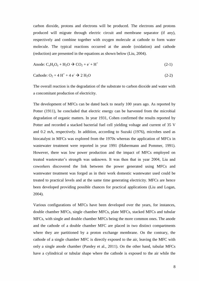
Various configurations of MFCs have been developed over the years, for instances,
double chamber MFCs, single chamber MFCs, plate MFCs, stacked MFCs and tubular
MFCs, with single and double chamber MFCs being the more common ones. The anode
and the cathode of a double chamber MFC are placed in two distinct compartments
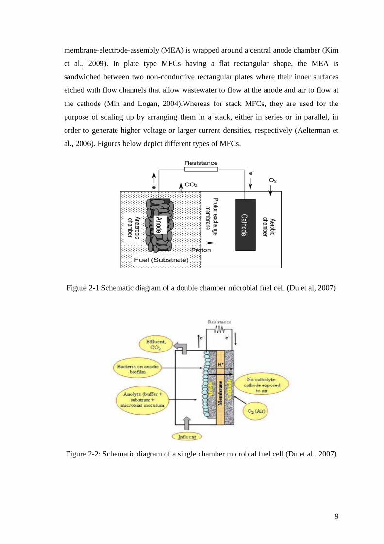
where they are partitioned by a proton exchange membrane. On the contrary, the
cathode of a single chamber MFC is directly exposed to the air, leaving the MFC with
only a single anode chamber (Pandey et al., 2011). On the other hand, tubular MFCs
have a cylindrical or tubular shape where the cathode is exposed to the air while the
9
membrane-electrode-assembly (MEA) is wrapped around a central anode chamber (Kim
et al., 2009). In plate type MFCs having a flat rectangular shape, the MEA is
sandwiched between two non-conductive rectangular plates where their inner surfaces
etched with flow channels that allow wastewater to flow at the anode and air to flow at
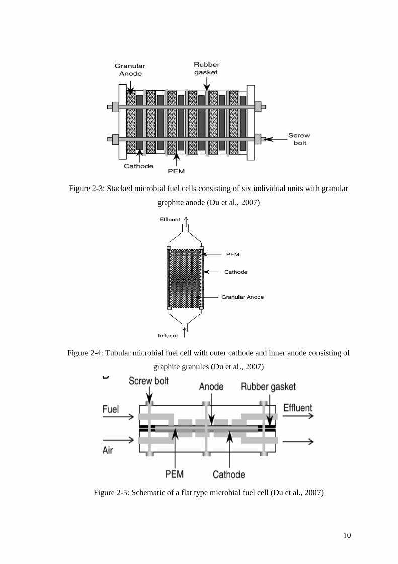
the cathode (Min and Logan, 2004).Whereas for stack MFCs, they are used for the
purpose of scaling up by arranging them in a stack, either in series or in parallel, in
order to generate higher voltage or larger current densities, respectively (Aelterman et
al., 2006). Figures below depict different types of MFCs.
Figure 2-1:Schematic diagram of a double chamber microbial fuel cell (Du et al, 2007)
Figure 2-2: Schematic diagram of a single chamber microbial fuel cell (Du et al., 2007)
10
Figure 2-3: Stacked microbial fuel cells consisting of six individual units with granular
graphite anode (Du et al., 2007)
Figure 2-4: Tubular microbial fuel cell with outer cathode and inner anode consisting of
graphite granules (Du et al., 2007)
Figure 2-5: Schematic of a flat type microbial fuel cell (Du et al., 2007)
11
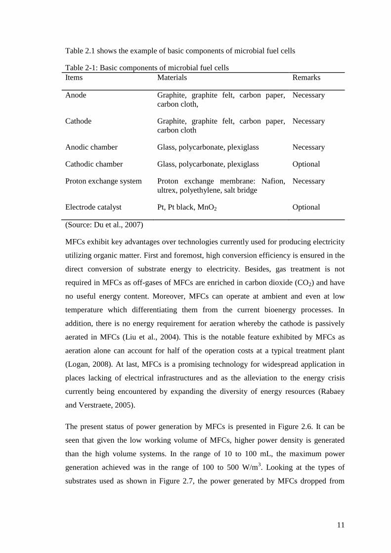
Table 2.1 shows the example of basic components of microbial fuel cells
Table 2-1: Basic components of microbial fuel cells
Items Materials Remarks
Anode Graphite, graphite felt, carbon paper,
carbon cloth,
Necessary
Cathode Graphite, graphite felt, carbon paper,
carbon cloth
Necessary
Anodic chamber Glass, polycarbonate, plexiglass Necessary
Cathodic chamber Glass, polycarbonate, plexiglass Optional
Proton exchange system Proton exchange membrane: Nafion,
ultrex, polyethylene, salt bridge
Necessary
Electrode catalyst Pt, Pt black, MnO2 Optional
(Source: Du et al., 2007)
MFCs exhibit key advantages over technologies currently used for producing electricity
utilizing organic matter. First and foremost, high conversion efficiency is ensured in the
direct conversion of substrate energy to electricity. Besides, gas treatment is not
required in MFCs as off-gases of MFCs are enriched in carbon dioxide (CO2) and have
no useful energy content. Moreover, MFCs can operate at ambient and even at low
temperature which differentiating them from the current bioenergy processes. In
addition, there is no energy requirement for aeration whereby the cathode is passively
aerated in MFCs (Liu et al., 2004). This is the notable feature exhibited by MFCs as
aeration alone can account for half of the operation costs at a typical treatment plant
(Logan, 2008). At last, MFCs is a promising technology for widespread application in
places lacking of electrical infrastructures and as the alleviation to the energy crisis
currently being encountered by expanding the diversity of energy resources (Rabaey
and Verstraete, 2005).
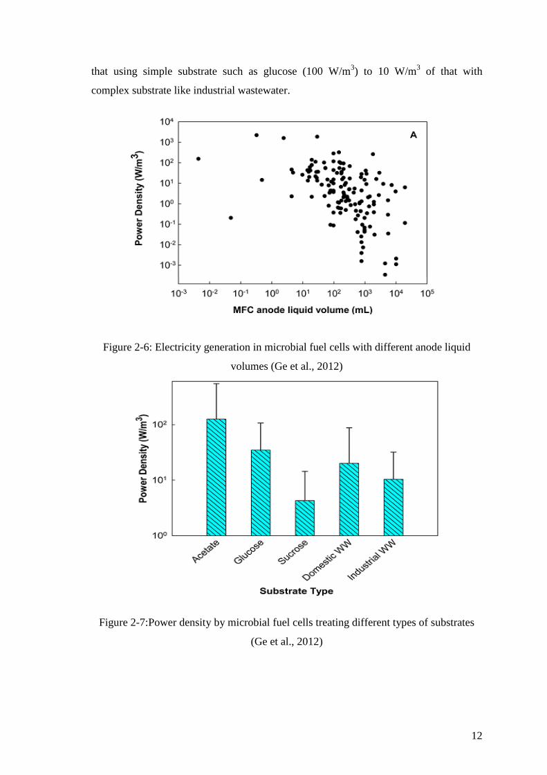
The present status of power generation by MFCs is presented in Figure 2.6. It can be
seen that given the low working volume of MFCs, higher power density is generated
than the high volume systems. In the range of 10 to 100 mL, the maximum power
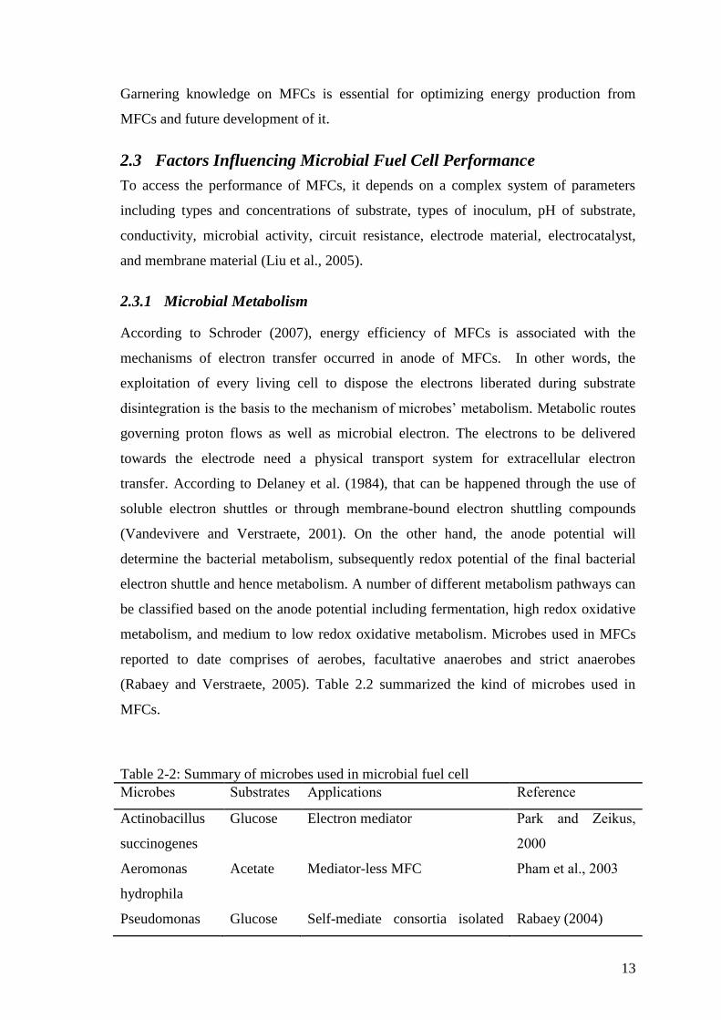
generation achieved was in the range of 100 to 500 W/m3. Looking at the types of
substrates used as shown in Figure 2.7, the power generated by MFCs dropped from
12
that using simple substrate such as glucose (100 W/m3) to 10 W/m
3 of that with
complex substrate like industrial wastewater.
Figure 2-6: Electricity generation in microbial fuel cells with different anode liquid
volumes (Ge et al., 2012)
Figure 2-7:Power density by microbial fuel cells treating different types of substrates
(Ge et al., 2012)
13
Garnering knowledge on MFCs is essential for optimizing energy production from
MFCs and future development of it.
2.3 Factors Influencing Microbial Fuel Cell Performance
To access the performance of MFCs, it depends on a complex system of parameters
including types and concentrations of substrate, types of inoculum, pH of substrate,
conductivity, microbial activity, circuit resistance, electrode material, electrocatalyst,
and membrane material (Liu et al., 2005).
2.3.1 Microbial Metabolism
According to Schroder (2007), energy efficiency of MFCs is associated with the
mechanisms of electron transfer occurred in anode of MFCs. In other words, the
exploitation of every living cell to dispose the electrons liberated during substrate
disintegration is the basis to the mechanism of microbes’ metabolism. Metabolic routes
governing proton flows as well as microbial electron. The electrons to be delivered
towards the electrode need a physical transport system for extracellular electron
transfer. According to Delaney et al. (1984), that can be happened through the use of
soluble electron shuttles or through membrane-bound electron shuttling compounds
(Vandevivere and Verstraete, 2001). On the other hand, the anode potential will
determine the bacterial metabolism, subsequently redox potential of the final bacterial
electron shuttle and hence metabolism. A number of different metabolism pathways can
be classified based on the anode potential including fermentation, high redox oxidative
metabolism, and medium to low redox oxidative metabolism. Microbes used in MFCs
reported to date comprises of aerobes, facultative anaerobes and strict anaerobes
(Rabaey and Verstraete, 2005). Table 2.2 summarized the kind of microbes used in
MFCs.
Table 2-2: Summary of microbes used in microbial fuel cell
Microbes Substrates Applications Reference
Actinobacillus
succinogenes
Glucose Electron mediator Park and Zeikus,
2000
Aeromonas
hydrophila
Acetate Mediator-less MFC Pham et al., 2003
Pseudomonas Glucose Self-mediate consortia isolated Rabaey (2004)
14
aeruginosa from MFC
Clostridium
beijerinckii
Starch Fermentative bacterium Niessen et al.
(2004b)
Desulfovibrio
desulfuricans
Sucrose Sulphate/sulphide as mediator Park et al., 1997)
Geobacter
metallireducens
Acetate Mediator-less MFC Min et al. (2005a)
Rhodoferax
ferrireducens
sucrose,
maltose
Mediator-less MFC Liu et al., 2006)
2.3.2 Types of Substrates
Apart from microbial metabolism, substrate is regarded as one of the prime factors
affecting MFC power generation (Liu et al., 2009). Substrate serves as carbon or
nutrient and energy source. According to Angenent and Wrennn, efficiency of
converting organic wastes to bioenergy depends on the chemical compositions as well
as concentrations of the components of waste material (2008). A broad spectrum of
substrates can be used in MFCs system for power generation ranging from pure
compounds such as glucose and organic acids, acetate, to complex mixtures of organic
matter present in industrial, domestic, and animal waste wastewater.
Acetate, being the simple substrate (Bond et al, 2002), has been utilized extensively as
the recalcitrance of multitude kinds of wastewater making them more difficult to be
used as substrate for electricity generation (Sun et al., 2009b). Besides, acetate is inert
towards alternative microbial conversions like fermentations and methanogenesis at
room temperature (Aelterman, 2009). Chae et el. demonstrated that MFCs fed with
acetate showed the highest CE (72.3%), followed by butyrate, propionate, and glucose
with readings of 43.0%, 36.0% and 15.0%, respectively (2009).
Another commonly used substrate in MFCs is glucose. A maximum power density of
216 W/m3 was obtained from a glucose-fed batch MFC using 100 mM ferric cyanide as
cathode oxidant (Rabaey et al., 2003). As reported by Hu (2008), a maximum power of
161 mW/m2 was generated in a baffle-chamber membraneless MFC inoculated with
anaerobic sludge and glucose.