Embed Size (px)
Citation preview
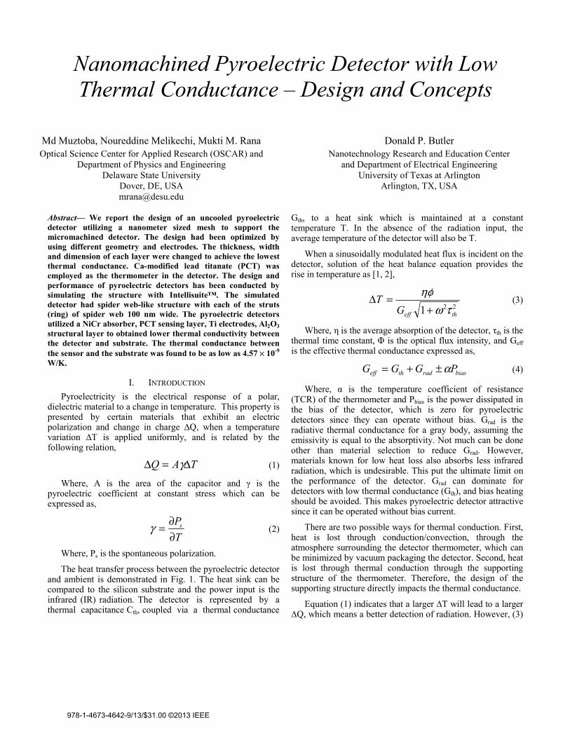
Nanomachined Pyroelectric Detector with Low Thermal Conductance – Design and Concepts
Md Muztoba, Noureddine Melikechi, Mukti M. Rana Optical Science Center for Applied Research (OSCAR) and
Department of Physics and Engineering Delaware State University
Dover, DE, USA [email protected]
Donald P. Butler Nanotechnology Research and Education Center
and Department of Electrical Engineering University of Texas at Arlington
Arlington, TX, USA
Abstract— We report the design of an uncooled pyroelectric detector utilizing a nanometer sized mesh to support the micromachined detector. The design had been optimized by using different geometry and electrodes. The thickness, width and dimension of each layer were changed to achieve the lowest thermal conductance. Ca-modified lead titanate (PCT) was employed as the thermometer in the detector. The design and performance of pyroelectric detectors has been conducted by simulating the structure with Intellisuite™. The simulated detector had spider web-like structure with each of the struts (ring) of spider web 100 nm wide. The pyroelectric detectors utilized a NiCr absorber, PCT sensing layer, Ti electrodes, Al2O3 structural layer to obtained lower thermal conductivity between the detector and substrate. The thermal conductance between the sensor and the substrate was found to be as low as 4.57 × 10⁻⁹ W/K.
I. INTRODUCTION Pyroelectricity is the electrical response of a polar,
dielectric material to a change in temperature. This property is presented by certain materials that exhibit an electric polarization and change in charge ∆Q, when a temperature variation ∆T is applied uniformly, and is related by the following relation,
TAQ Δ=Δ γ (1)
Where, A is the area of the capacitor and γ is the pyroelectric coefficient at constant stress which can be expressed as,
TPs
∂∂=γ (2)
Where, Ps is the spontaneous polarization.
The heat transfer process between the pyroelectric detector and ambient is demonstrated in Fig. 1. The heat sink can be compared to the silicon substrate and the power input is the infrared (IR) radiation. The detector is represented by a thermal capacitance Cth, coupled via a thermal conductance
Gth, to a heat sink which is maintained at a constant temperature T. In the absence of the radiation input, the average temperature of the detector will also be T.
When a sinusoidally modulated heat flux is incident on the detector, solution of the heat balance equation provides the rise in temperature as [1, 2],
221 theffGT
τωηφ
+=Δ (3)
Where, η is the average absorption of the detector, τth is the thermal time constant, Φ is the optical flux intensity, and Geff is the effective thermal conductance expressed as,
biasradtheff PGGG α±+= (4)
Where, α is the temperature coefficient of resistance (TCR) of the thermometer and Pbias is the power dissipated in the bias of the detector, which is zero for pyroelectric detectors since they can operate without bias. Grad is the radiative thermal conductance for a gray body, assuming the emissivity is equal to the absorptivity. Not much can be done other than material selection to reduce Grad. However, materials known for low heat loss also absorbs less infrared radiation, which is undesirable. This put the ultimate limit on the performance of the detector. Grad can dominate for detectors with low thermal conductance (Gth), and bias heating should be avoided. This makes pyroelectric detector attractive since it can be operated without bias current.
There are two possible ways for thermal conduction. First, heat is lost through conduction/convection, through the atmosphere surrounding the detector thermometer, which can be minimized by vacuum packaging the detector. Second, heat is lost through thermal conduction through the supporting structure of the thermometer. Therefore, the design of the supporting structure directly impacts the thermal conductance.
Equation (1) indicates that a larger ∆T will lead to a larger ∆Q, which means a better detection of radiation. However, (3)
978-1-4673-4642-9/13/$31.00 ©2013 IEEE

shows that Geff must be low for larger ∆T. see that for pyroelectric detectors, the econductance is due to mainly thermal condusupporting structure of the thermometer. conductivity between the heat sink and thermade as low as possible. In this work, the aset toward achieving lower thermal conductan
II. METHOD The goal of this work was to design an
having background limited detectivity, capabthe long wavelength IR region (8-14 temperature, without the need for cryogenic detectors are ideal for this effort since theroom temperature and among them pyroelecselected since it does not require any bias cand thus free of 1/f-noise. For bacperformance, thermal noise can be neglecachieve high detectivity, it is important equivalent power (NEP), which can be achilower noise and higher voltage responsivabsorption and low thermal conductance detector performance. Ni0.8Cr0.2 was used material due to its high absorption at infrare14 µm).
The sensor and absorber layers werseparated from the substrate by a spidedesigned with meandered struts, which conduction of heat energy from the sensor twell as interface circuitry. The electrmeandered to avoid heat loss. Fig. 2 showsdesign of spider web support along with the this work. Al2O3 was used as the spider webhas high yield strength (15.4 GPa), low ther(0.25 W/cm/K), and high optical transmitt
Figure 1. Heat transfer process of a pyroelectric detector [3]
Figure 3. Geometry of the pyroelectric detector
Figure. 2. Geometry of the spider web
Al2O3 Spider Web Support
From (4), we can effective thermal
uction through the So, the thermal
rmometer must be aim was therefore nce.
n infrared detector ble of operating in
µm), at room cooling. Thermal
ey can operate at ctric detector was current to operate
ckground limited cted. In order to to reduce noise
ieved by ensuring vity. So, high IR
are vital for the as the absorber
ed frequencies (8-
re supported and er web structure
helped in low to the substrate as rodes were also s top view of the electrodes used in b material since it rmal conductivity tance (~0.9). The
evolution of electron-beam lithogradeep ultraviolet lithography has enato be patterned. So, study of 50 tofeasible. Ti was selected as the electrelatively lower thermal conductivitywith high electrical conductivity of 4
Ca modified lead titanate was cmaterial because of its good pyroel10-9 Ccm-2K-1 and figure of merit of substrate was used because of itsmechanical properties.
Geometry of the structure is shoand analysis of the pyroelectric detIntelliSuite® software. Several IntelliMask, FabViewer, 3DBuildeMechanical (TEM) were used to deach layer and generate 3-D models,by finite element analysis (FEM) me
III. RESUL
b support and electrodes
Ti Electrode
aphy, nanoimprinting, and abled sub-100nm features o 100nm strut width was trode material since it has y of 0.219 W/cm/K along
4.2 × 10⁻⁷ Ω-m.
chosen as the pyroelectric lectric coefficient of 43 × f 2340 V cm-2J-1 [3]. A Si s excellent electrical and
own in Fig. 3. The design tector was done by using modules, for instance,
er, and Thermo Electro design the photomasks of
to perform the simulation thod.
LT

(a) (b)
(c) (d)
(e) (f)
Figure 4. Effect of (a) web diameter, (b) web structure thickness, (c) electrode thickness , (d) sensing layer thickness, (e) strut width, and (f) number of struts on thermal conductance.
0.00E+00
1.00E-08
2.00E-08
3.00E-08
4.00E-08
30 50 70 90
Gth
(W/K
)
Web Diameter (µm)
4.20E-09
4.30E-09
4.40E-09
4.50E-09
4.60E-09
0.1 0.3 0.5 0.7 0.9
Gth
(W/K
)
Web Structure Thickness (µm)
3.80E-09
4.30E-09
4.80E-09
0.1 0.6 1.1 1.6
Gth
(W/K
)
Electrode Thickness (µm)
4.30E-094.40E-094.50E-094.60E-094.70E-094.80E-094.90E-09
0.5 1.5 2.5 3.5
Gth
(W/K
)
Sensing Layer Thickness (µm)
3.80E-09
4.00E-09
4.20E-09
4.40E-09
4.60E-09
4.80E-09
50 60 70 80 90 100
Gth
(W/K
)
Strut Width (nm)
0.00E+00
1.00E-08
2.00E-08
3.00E-08
4.00E-08
5.00E-08
3 23 43 63
Gth
(W/K
)
Number of Struts
The effects of strut number, thickness, dimension, and width of different layers on thermal conductance were studied.
Thermal conductance of the structure was calculated from,
IT
AG dth Δ
= (5)
Where, Ad is the area of the absorber and I is the intensity of the heat flux. Heat flux of 50 pW/µm2 was applied on top of the absorber. The bottom of the substrate was kept fixed at 25oC or 298K which is the room temperature.
In this paper, we only report the variations of thermal conductance with respect to different parameters. Increasing
the dimension of the spider web structure led to lower thermal conductance as shown in Fig. 4(a). The thermal conductance for heat conduction process is related to the path length (L) according to the Fourier's law for heat conduction as,
κLAGth = (6)
Where, A is the area of the plane perpendicular to the direction of heat conduction andκ is the thermal conductivity of the material.

A larger web structure had a longer path length which caused lower thermal conductance. However, an increase in the web structure size means a bulkier detector. So it put a limit on this step.
Because of lower thermal resistance due to larger cross-sectional area of thicker web structure, as can be seen from (6), the device showed increasing thermal conductance with increase in thickness of web structure. This effect is shown in Fig. 4(b).
In the study of the effect of thickness of electrodes on thermal conductance (see Fig. 4(c)), it was found that thermal conductance was decreasing with decrease in electrode thickness. The reason behind this can be explained using (6). Smaller thickness led to smaller cross-sectional area which provided a higher thermal resistance for conductive heat to transfer.
A thicker sensing layer provides longer thermal path which helps in temperature rise. However, increase in thermal mass tends to increase thermal conductance. So, there was a race between these two factors and lower thermal conductance was found with increasing sensing layer thickness as demonstrated in Fig. 4(d).
Study of strut width showed that decreased width can provide lower thermal conductance (see Fig. 4(e)). Struts with smaller width have smaller cross-sectional area and thus
provide higher thermal resistance. Thus lower conduction can be planned.
It was observed that number of struts has a paramount effect on thermal conductance as shown in Fig. 4(f). Addition of struts provided longer thermal path length and hence reduced thermal conductance.
The thermal conductance between the sensor and the substrate (heat sink) was obtained as low as 4.57 × 10⁻⁹ W/K compared to the radiative thermal conductance of 3.69 ×10⁻⁷ W/K. Such low thermal conductivity will yield a high sensitivity detector.
ACKNOWLEDGMENT This work was supported in part by National Science
Foundation under Grants CREST HRD-0630388, CREST HRD-1242067 and NASA URC NNX09AU90A.
REFERENCES [1] A. Rogalski, “Infrared detectors: status and trends,” Progress in
Quantum Electronics, vol. 27, pp. 59-210, 2003. [2] A. Rogalski, “Infrared thermal detectors versus photon detectors: I.
Pixel performance,” Material science and material properties for infrared optoelectronics, proceedings, vol. 3182, pp. 14-25, 1997.
[3] S. G. Porter, “A brief guide to pyroelectric detectors,” Ferroelectrics, vol. 33, pp. 193-206, 1981.