Embed Size (px)
Citation preview

1
EML 4905 Senior Design Project
A B.S. THESIS PREPARED IN PARTIAL FULFILLMENT OF THE
REQUIREMENT FOR THE DEGREE OF BACHELOR OF SCIENCE
IN MECHANICAL ENGINEERING
NANOLAUNCH REACTION CONTROL SYSTEM
Final Report
David Dominguez Gianni Jimenez
Genesis Vasquez
Advisor: Professor George Dulikravich
November 24, 2014
This B.S. thesis is written in partial fulfillment of the requirements in EML 4905. The contents represent the opinion of the authors and not the
Department of Mechanical and Materials Engineering.
1
ETHICS STATEMENT AND SIGNATURES
The work submitted in this B.S. thesis is solely prepared by a team consisting of David Dominguez, Gianni Jimenez, and Genesis Vasquez and it is original. Excerpts from others’ work have been clearly identified, their work acknowledged within the text and listed in the list of references. All of the engineering drawings, computer programs, formulations, design work, prototype development and testing reported in this document are also original and prepared by the same team of students.
David Dominguez Team Leader
Gianni Jimenez Team Member
Genesis Vasquez Team Member
Dr. George Dulikravich
Faculty Advisor
2
TABLE OF CONTENTS
ETHICS STATEMENT AND SIGNATURES ............................................................................................ 1
TABLE OF CONTENTS .......................................................................................................................... 2
LIST OF FIGURES .............................................................................................................................. 4
LIST OF TABLES ............................................................................................................................... 5
ABSTRACT .................................................................................................................................... 6
1. INTRODUCTION ................................................................................................................... 7
1.1 PROBLEM STATEMENT .......................................................................................................... 7
1.2 MOTIVATION ......................................................................................................................... 9
1.3 LITERATURE SURVEY .......................................................................................................... 10
1.3.1 CUBESAT ........................................................................................................................ 10
1.3.2 NASA’S NANOLAUNCH PROGRAM .................................................................................. 10
1.3.3 ATTITUDE CONTROL ....................................................................................................... 13
1.3.4 TYPES OF ACTUATORS .................................................................................................... 14
1.3.4.1 MOVEABLE FINS .......................................................................................................... 14
1.3.4.2 THRUST VANES ........................................................................................................... 15
1.3.4.3 GIMBALS ..................................................................................................................... 16
1.3.4.4 VERNIER ROCKETS ...................................................................................................... 17
1.3.5 ROTARY VALVES ............................................................................................................ 18
2. PROJECT FORMULATION ................................................................................................ 19
2.1 PROJECT OBJECTIVES .......................................................................................................... 19
2.2 DESIGN SPECIFICATIONS ..................................................................................................... 20
2.3 ADDRESSING GLOBAL DESIGN ............................................................................................ 23
2.4 CONSTRAINTS AND OTHER CONSIDERATIONS ..................................................................... 24
3. DESIGN ALTERNATIVES.................................................................................................. 26
3.1 OVERVIEW OF CONCEPTUAL DESIGN .................................................................................. 26
3.2 DESIGN ALTERNATE 1 ........................................................................................................ 28
3.3 DESIGN ALTERNATE 2 ........................................................................................................ 30
3.4 FINAL PROPOSED DESIGN ................................................................................................... 32
3.4.1 MANIFOLD ...................................................................................................................... 32
3.4.2 VALVE............................................................................................................................. 33
3.4.3 STEPPER MOTOR ............................................................................................................. 35
3.4.4 ON/OFF VALVE ............................................................................................................... 36
3.4.5 RCS CONTROLLER .......................................................................................................... 36
3.4.6 ASSEMBLY ...................................................................................................................... 37
3.5 PRODUCTION OPTIONS ........................................................................................................ 38
3.5.1 TRADITIONAL MACHINING .............................................................................................. 38
3.5.2 3D PRINTING ................................................................................................................... 38
4. PROJECT MANAGEMENT ................................................................................................ 41
4.1 OVERVIEW .......................................................................................................................... 41
4.2 GANTT CHART FOR THE ORGANIZATION OF WORK AND TIMELINE ..................................... 41
4.3 BREAKDOWN OF RESPONSIBILITIES AMONG TEAM MEMBERS ............................................ 41
4.4 POTENTIAL FOR COMPETITION ............................................................................................ 42
5. ENGINEERING DESIGN AND ANALYSIS ...................................................................... 43
5.1 OVERVIEW .......................................................................................................................... 43

3
5.2 ENGINEERING CALCULATIONS ............................................................................................ 43
5.3 STRESS AND PRESSURE SIMULATIONS................................................................................. 46
5.4 COST ANALYSIS .................................................................................................................. 48
6. PROTOTYPE CONSTRUCTION ........................................................................................ 49
6.1 PROTOTYPE SYSTEM DESCRIPTION ..................................................................................... 49
6.2 COMPLETED PROTOTYPE DESIGN ....................................................................................... 50
6.2.1 VALVE AND MANIFOLD ................................................................................................... 51
6.2.2 PIPING ARANGEMENT ...................................................................................................... 51
6.2.3 TESTING APPARATUS ...................................................................................................... 52
6.3 PARTS LIST ......................................................................................................................... 55
6.4 PROTOTYPE COST ANALYSIS .............................................................................................. 56
7. TESTING AND EVALUATION .......................................................................................... 58
7.1 OVERVIEW .......................................................................................................................... 58
7.2 DESIGN OF EXPERIMENTS ................................................................................................... 60
7.3 TEST RESULTS AND DATA................................................................................................... 61
8. DESIGN CONSIDERATIONS ............................................................................................. 62
8.1 ASSEMBLY .......................................................................................................................... 62
8.2 DISASSEMBLY AND MAINTENANCE..................................................................................... 62
8.3 ENVIRONMENTAL IMPACT ................................................................................................... 63
8.4 RISK ASSESSMENT .............................................................................................................. 64
9. DESIGN EXPERIENCE ....................................................................................................... 65
9.1 OVERVIEW .......................................................................................................................... 65
9.2 STANDARDS USED IN THE PROJECT ..................................................................................... 65
9.3 IMPACT OF DESIGN IN A GLOBAL AND SOCIETAL CONTEXT ................................................ 66
9.4 PROFESSIONAL AND ETHICAL RESPONSIBILITY ................................................................... 66
9.5 LIFE-LONG LEARNING EXPERIENCE .................................................................................... 67
10. CONCLUSION .................................................................................................................. 68
10.1 CONCLUSION AND DISCUSSION ........................................................................................... 68
10.2 COMMERCIALIZATION PROSPECTS OF THE PRODUCT .......................................................... 68
10.3 FUTURE WORK ................................................................................................................... 69
11. REFERENCES .................................................................................................................. 71
12. IMAGE CREDITS ............................................................................................................. 73
13. APPENDICES ................................................................................................................... 74
13.1 APPENDIX A: DRAWINGS .................................................................................................... 74
13.2 APPENDIX B: PROOF OF PROJECT PRODUCTION STATUS ..................................................... 76
13.3 APPENDIX C: ORIGINAL SWAGELOK QUOTE ....................................................................... 77
13.4 APPENDIX D: STANDARDS, CODES, SPECIFICATIONS AND TECHNICAL REGULATIONS .......... 79
13.5 APPENDIX E: RAW DATA FROM VOLUMETRIC FLOW EXPERIMENT .................................... 80

4
LIST OF FIGURES
Figure 1 – Picture of the 3U Gene Sat 1 and the Mark II P-POD (17) ......................................... 10
Figure 2 – Comparison of Traditional Launch Vehicle with the Nanolaunch Vehicle ................ 12
Figure 3 – Movable Fin Illustration .............................................................................................. 14
Figure 4 – Thrust Vane Illustration ............................................................................................... 15
Figure 5 – Gimbaled Thrust Illustration ....................................................................................... 16
Figure 6 – Vernier Rocket Illustration .......................................................................................... 17
Figure 7 – Diagram of a rotary valve commonly used in brass instruments (19) ......................... 18
Figure 8 – Nanolaunch Program Expected RCS Activation Points .............................................. 19
Figure 9 – RCS location within Nanolaunch vehicle .................................................................... 20
Figure 10 – RCS location and space under shroud for propellant tanks ....................................... 21
Figure 11 – Mockup of rocket stages ............................................................................................ 21
Figure 12 – NASA-Proposed RCS Version 1 ............................................................................... 24
Figure 13 – NASA-Proposed RCS Version 2 (Roll Test) ............................................................ 25
Figure 14 – Rotating Valve System (Manifold) ........................................................................... 26
Figure 15 – Rotary valve (solid grey) that provides 4 different exit combinations ...................... 27
Figure 16 – Rocket cross section showing required firing combinations ..................................... 27
Figure 17 – Exploded view of the parts ........................................................................................ 28
Figure 18 – Rendered model shown in 3D printed enclosure ....................................................... 29
Figure 19 – 3D print of the valve made at NASA ........................................................................ 29
Figure 20 – Second design ............................................................................................................ 30
Figure 21 – Flow analysis in SolidWorks ..................................................................................... 31
Figure 22 – Current RCS Manifold Design .................................................................................. 32
Figure 23 – Current RCS Valve Design ....................................................................................... 33
Figure 24 – Current RCS Assembly Design ................................................................................. 34
Figure 25 – Current Stepper Motor Model ................................................................................... 35
Figure 26 – Current RCS Switch Valve ........................................................................................ 36
Figure 27 – Complete RCS Assembly Design .............................................................................. 37
Figure 28 – Prototype Tolerances ................................................................................................. 39
Figure 29 – Manifold showing 0.015" step for valve seal ............................................................ 40
Figure 30 – Projected project timeline chart ................................................................................. 41
Figure 31 – Stress analysis on rotary valve .................................................................................. 46
Figure 32 – Pressure simulation for valve channel ....................................................................... 47
Figure 33 – The three prototypes together .................................................................................... 50
Figure 34 – Assembled Prototype ................................................................................................. 50
Figure 35 – Final Test Setup ......................................................................................................... 53
Figure 36 – Testing with tank and servo control .......................................................................... 54
Figure 37 – Current NASA RCS Prototype .................................................................................. 59
Figure 38 – Compressed Air Tank Warning Label ....................................................................... 64
Figure 39 – Weld-ready valve on the left ..................................................................................... 69
Figure 40 – Various types of on/off valves that could be used ..................................................... 70
Figure 41 – Shapeways Receipt .................................................................................................... 76
5
LIST OF TABLES
Table 1 – Minor Loss Coefficients ............................................................................................... 45
Table 2 – Complete List of Parts Used ......................................................................................... 55
Table 3 – Complete List of Parts Purchased ................................................................................. 57
Table 4 – Volumetric Flow Rate Experimental Data.................................................................... 80
6
ABSTRACT
This project involves the design, analysis, manufacture, and testing of a reaction control
system (RCS) for an orbital launch vehicle suitable for NASA’s Nanolaunch program. The goal
of the project is a cheap, reliable RCS that will help lower the cost of entry into space
experimentation for universities. Our design reduces the number of failure modes of the baseline
NASA RCS design, and is half the weight at one-third the cost.

7
1. INTRODUCTION
1.1 PROBLEM STATEMENT
The goal of our project is to develop a reaction control system (RCS) that reduces cost,
mass, volume, and complexity as compared with existing designs, in order to open up space
experimentation to a larger number of universities. NASA’s baseline RCS design for launch
vehicles developed under the Nanolaunch program uses four on/off solenoid switches with
various pipe adapters to control four cold gas (CO2) thrusters. The proposed design uses a single
selector valve and one solenoid switch. The selector valve will be controlled by a stepper motor,
which will align the ports needed for proper RCS operation. Pitch, yaw, and bi-directional
rotation will be possible with the current port combination. The RCS was designed with
SolidWorks and will be analyzed with SolidWorks Flow Simulator, ANSYS, and other software
as resources become available.
A prototype was 3D printed out of 540 stainless steel and tested with compressed air.
Once the concept has been proven, the RCS manifold and valve will be 3D printed in titanium
using fabrication resources at NASA Marwill Space Flight Center (MSFC) to be used with a
carbon fiber 4500 PSI tank regulated down to 1150 PSI (31 MPa to 8 MPa). The required force
per RCS activation is currently set at 2.25-3.37 lbf (10-15 N). The theoretical calculations for our
design estimate 28 lbf (125 N) with an 1150 PSI (7.6 MPa) regulator using ¼” ID tubing, and
18.4 lbf (82 N) using our 750 PSI (5 MPa) test tank. Our estimation assumes half the regulator
pressure at the nozzles. This allows flexibility in the event of requirement changes, flow losses,
and other unknown effects.
Our concept eliminates the heavy pipe adapter fittings, reduces the failure points due to
the elimination of pipe connection points and solenoid switches, and reduces the cost of parts.

8
The incorporation of our design into a future Nanolaunch vehicle will enable NASA to meet
their budget requirements and offer universities affordable access to space for their orbital
experiments.

9
1.2 MOTIVATION
Conceived as a skunkworks project at MSFC, interest in the Nanolaunch program has
grown among center management as well as NASA engineers, gaining the program more
funding and manpower over the last year. Recently, NASA has made Nanolaunch an official,
fully funded technology development program with dedicated full-time employees. As part of
the Nanolaunch program, NASA encourages collaboration with academia by allowing
universities to submit ideas for various launch vehicle subsystems, which may be incorporated
into the system design if proven to meet vehicle requirements at minimal cost.
In order to design an effective low-cost RCS, it is first essential to become familiar with
the program requirements for which the system will be designed. In addition, it is necessary to
analyze current and historical methods of controlling the translation and attitude of spacecraft.
Finally, different technologies will be analyzed for potential use in this application.

10
1.3 LITERATURE SURVEY
1.3.1 CUBESAT
The CubeSat standard was designed to standardize the size and shape of nanosatellites
sent into orbit for ease of cargo bay space allotments and launch mechanism design. (1) A
standard CubeSat measures 10x10x10 cm (3.93 in3), weighs no more than 1.33 kg (2.93 lbs) and
is called a “1U” CubeSat. CubeSats dimensions can be increased in 1U increments, allowing for
the launch of 2U (20x10x10 cm) and 3U (30x10x10 cm) modules.
The Poly-Picosatellite Orbital Deployer (P-POD) was designed to carry and launch 3U or
6U CubeSat units from a spacecraft. Any CubeSat project will require that the launch craft be
fitted with a P-POD.
Figure 1 – Picture of the 3U Gene Sat 1 and the Mark II P-POD (17)
1.3.2 NASA’S NANOLAUNCH PROGRAM
NASA’s Nanolaunch program is designed to make space more accessible to
governmental, commercial, academic, and research entities by lowering the cost of launches.

11
(NASA, n.d.) Currently, sending an experiment module into space requires finding a spacecraft
scheduled for future launch that has enough payload space and has the right components to
launch the module at the correct altitude (usually with the P-POD system). Finding a launch
vehicle that meets these requirements is difficult, and is further complicated by the high costs of
launching. For example, the current average cost to launch a 1U CubeSat with an independent
launch agency is $100,000 to $125,000. (1)
For the academic community, timing is a critical issue since the delay of an experiment
launch can delay the graduation of students whose research thesis depends on the results. For this
reason, NASA initiatives dedicated solely to the launching of CubeSats are considered preferable
to cheaper, less reliable commercial alternatives. The Educational Launch of Nanosatellites
(ELaNa) project, for example, is tailored primarily for the delivery of academic CubeSATS. (3)
However, the high price of the launches means that relatively few of them are sent off each year.
The Nanolaunch initiative seeks to increase the number of launches available for CubeSats by
reducing this prohibitively high cost.

12
Figure 2 – Comparison of Traditional Launch Vehicle with the Nanolaunch Vehicle

13
1.3.3 ATTITUDE CONTROL
When discussing spacecraft, the word “attitude” refers to the vehicle’s orientation in
space. In order to control attitude, the craft first requires sensors that can be used to determine
the current orientation. Once it has determined its current position and the position it needs to
attain for the next part of the mission, computer algorithms can then calculate how to effectuate
this change in attitude. This is then carried out by the use of actuators, which apply force and/or
torque to move the vehicle. Together, these components make up the guidance, navigation and
control system (GN&C) of a spacecraft. (5) The scope of our project concentrates on the actuator
portion of this system, to be designed specifically for the requirements of NASA’s Nanolaunch
program.

14
1.3.4 TYPES OF ACTUATORS
The development of rockets in the 20th century led to many innovations in improving
rocket stability and in reducing its weight. Previous methods of ensuring a rocket’s stability, such
as bent fins that caused rockets to spin rapidly and stabilize (thereby increasing drag), were
abandoned in favor of active controls, which use the intelligence of a computer to actuate a
vehicle in a precise and efficient manner. (7)
1.3.4.1 MOVEABLE FINS
In order to redirect a rocket or air-to-air missile, moveable fins can change the amount of
aerodynamic force by deflecting in the desired direction. The resultant opposing torque around
the rocket’s center of pressure will cause it to turn in the desired way, similar to a rudder. (18)
Figure 3 – Movable Fin Illustration

15
1.3.4.2 THRUST VANES
Thrust vanes are mobile fins placed in the engine that can tilt to deflect the exhaust
leaving the rocket’s engine, and this action causes its nose to turn the opposite way, redirecting
the rocket’s flight path. This was used on the V2 and Redstone rockets, but is not currently in
use. (18)
Figure 4 – Thrust Vane Illustration

16
1.3.4.3 GIMBALS
Rockets using gimbals for reaction control have the exit nozzle from the engine free to
rotate, allowing it to redirect the engine’s thrust as needed. Most modern full-size rockets utilize
this method to control and stabilize their course. (18) This system is extremely complex and
expensive.
Figure 5 – Gimbaled Thrust Illustration

17
1.3.4.4 VERNIER ROCKETS
Vernier rockets are small rockets attached to the outside or bottom of the spacecraft and
angled to produce torque. They fire to change the course of the vehicle- firing one will change
the direction by rotating the craft while firing two at a time will cause translation. This is mostly
in use only on older craft, as this requires plenty of additional fuel and plumbing in order to
function, and therefore plenty of additional weight is required. (18)
Figure 6 – Vernier Rocket Illustration
For this technology to be viable for use in a smaller craft, the plumbing required would
have to be severely reduced.
18
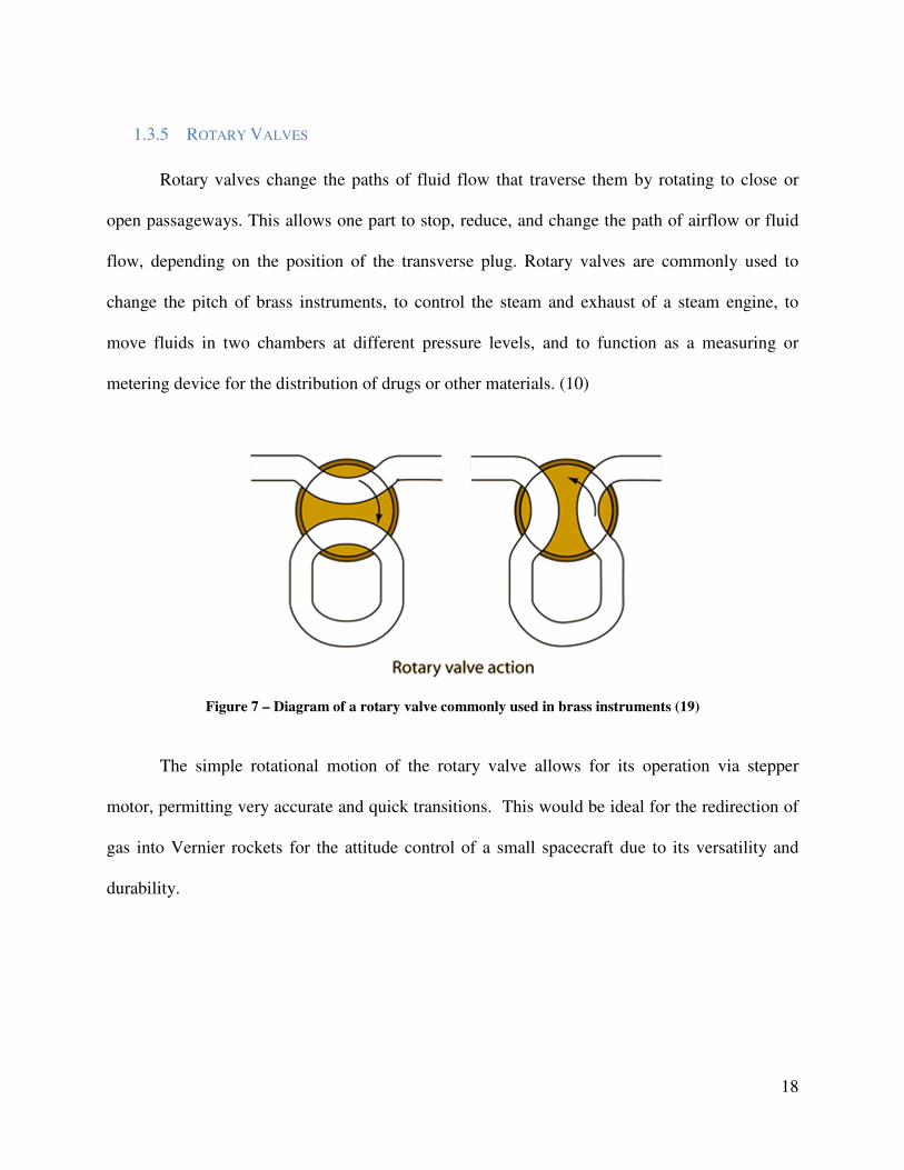
1.3.5 ROTARY VALVES
Rotary valves change the paths of fluid flow that traverse them by rotating to close or
open passageways. This allows one part to stop, reduce, and change the path of airflow or fluid
flow, depending on the position of the transverse plug. Rotary valves are commonly used to
change the pitch of brass instruments, to control the steam and exhaust of a steam engine, to
move fluids in two chambers at different pressure levels, and to function as a measuring or
metering device for the distribution of drugs or other materials. (10)
Figure 7 – Diagram of a rotary valve commonly used in brass instruments (19)
The simple rotational motion of the rotary valve allows for its operation via stepper
motor, permitting very accurate and quick transitions. This would be ideal for the redirection of
gas into Vernier rockets for the attitude control of a small spacecraft due to its versatility and
durability.

19
2. PROJECT FORMULATION
2.1 PROJECT OBJECTIVES
Requirements for the RCS system are as follows:
a. The reaction control system will fit in a cylindrical body with the following
measurements: Diameter of 8 inches (20.3 cm) and length of 24 inches (60.9 cm).
b. Logos: NASA’s official logo will be used when presenting posters, papers, and on the
final build. No written permission was granted, but the project was advised and approved
by David Dominguez’s internship advisor in 2013 to proceed with David’s idea of a
rotary valve system for the senior design course.
c. Testing: The working prototype will be completed within two months of the start of the
semester, at which point we will begin testing, complying with NASA testing codes for
safety.
Figure 8 – Nanolaunch Program Expected RCS Activation Points

20
2.2 DESIGN SPECIFICATIONS
The RCS must fit within the designated space in the vehicle, and all components must be
able to withstand the force of the pressurized gas. The RCS must also be securely anchored to the
craft in order to rotate it as needed. The current planned location for the RCS can be seen below
in Figure 9. The figure shows the third, fourth, and fifth stages, along with the payload. It will be
in this configuration that the RCS will first activate. The weight of the vehicle at this stage is
approximately 1100 pounds (500 kg).
Figure 9 – RCS location within Nanolaunch vehicle
Figure 10 shows the vehicle with the shroud in place. Transparency has been applied to
the shroud to gauge the volume allotment for the RCS system. The tanks containing the
pressurized gas will fit between the upper stages and the shroud. The diameters of the shroud and

21
fourth stage are 18 and 10 inches respectively (45.7 and 25.4 cm). This provides for
approximately 3.5 inch (8.9 cm) wide ring around the fourth stage for tanks.
Figure 10 – RCS location and space under shroud for propellant tanks
Figure 11 shows a full-scale mock-up of the last two stages. The stands for the stages are
measured for the purpose of showing the distance to the shroud.
Figure 11 – Mockup of rocket stages

22
The specific placement of the RCS valve and associated tubing is still to be determined
by NASA. The exhaust nozzles will be placed as close to the shroud as allowable for a larger
moment arm and thus more effective control. An extendable system is also possible. Once the
shroud is ejected, arms can extend to rotate the RCS tubing to a wider position and lock in place,
thereby increasing the torque even more.

23
2.3 ADDRESSING GLOBAL DESIGN
Due to the economical nature of the proposed RCS, the successful use of this design in
Nanolaunch missions may lead to future use on similar initiatives by foreign space agencies.
Apart from NASA, there are twelve other space agencies currently capable of launches,
including the European Space Agency (ESA), the French National Center of Space Research
(CNES), the Russian Federal Space Agency (RFSA), and the China National Space
Administration (CNSA). Recognizing this, all dimensions in this report have been given in both
imperial and metric units for the convenience of the reader.

24
2.4 CONSTRAINTS AND OTHER CONSIDERATIONS
The goal of this project is to create a more economical RCS than the current prototype
that has been developed at NASA while maintaining the same level of functionality and
reliability. For the project to be considered successful, the completed prototype must be able to
perform the same roll, pitch, and yaw functions at a fraction of the current cost.
NASA engineers are currently using one on/off valve for each of the four thrusters on
their RCS design. This design is heavier due to the tube interfaces; is more prone to failure with
four times the chance of a valve failing, (not including the additional chances of failure due to
the extra interfaces); and costs four times as much as our proposed design. Each on/off valve
costs $363 on its own.
Figure 12 – NASA-Proposed RCS Version 1

25
Figure 13 – NASA-Proposed RCS Version 2 (Roll Test)

26
3. DESIGN ALTERNATIVES
3.1 OVERVIEW OF CONCEPTUAL DESIGN
Our proposed system consists of a rotating valve (shown in solid yellow in Figure 14)
within a manifold. The valve will be rotated by a stepper motor to align the ports according to
the desired thrust mechanics. An on/off valve will then open briefly to pulse the high-pressure
cold gas through the nozzles to roll or pitch the vehicle. The rotary valve was designed to have
four different combinations for the exit nozzles that will control the rocket after Phase 1 of the
launch. This can be seen in Figures 11-13.
Figure 14 – Rotating Valve System (Manifold)
In
Out Out

27
Figure 15 – Rotary valve (solid grey) that provides 4 different exit combinations
Figure 16 shows the combinations of thruster firing (numbered arrows outside the circles)
and the effect of the firing (orange arrows inside circles). The left two are the two possible roll
directions and the right two are the pitch directions. For yaw, the vehicle rolls to one side and
then a pitch combination is used.
Figure 16 – Rocket cross section showing required firing combinations

28
3.2 DESIGN ALTERNATE 1
Our first design of the RCS valve itself consisted of 19 parts, as seen in Figure 17 below.
Gas would flow into the manifold through an off-center port on the top. Channels in the rotating
valve would funnel the gas into two orifices that would expel the gas through the desired exit
ports. The flow diameter was only 1/8”.
Figure 17 – Exploded view of the parts

29
Figure 18 shows this first design of the RCS valve system installed in an 8-inch (20.3 cm)
3D-printed fuselage with built in nozzles, for mounting on a test vehicle consisting of a Wildman
Ultimate Class III amateur rocket.
Figure 18 – Rendered model shown in 3D printed enclosure
The valve was 3D printed by NASA in March 2014 to have a physical prototype to help
analyze the design. The print was not high resolution enough to allow for proper fit and seal of
the parts.
Figure 19 – 3D print of the valve made at NASA

30
3.3 DESIGN ALTERNATE 2
Our second design increased the flow diameter to 1/4” (.635 cm) which greatly increased
the force of the RCS. It was 3D-printed by a Makerbot at Florida International University’s
Engineering Manufacturing Center (FIU EMC). This valve was 2.9” (7.4 cm) in diameter and
1.75” (4.4 cm) tall.
Figure 20 – Second design
An initial simple flow analysis was done with the second design in SolidWorks to ensure
the gas would flow out of both ports equally in a vacuum. This flow simulation can be seen in
Figure 18.

31
Figure 21 – Flow analysis in SolidWorks

32
3.4 FINAL PROPOSED DESIGN
3.4.1 MANIFOLD
The purpose of the manifold is to hold the valve system in position (four-bolt mount) and
to provide a point of entry for the compressed cold gas and multiple points of exit for proper
nozzle firing.
Figure 22 – Current RCS Manifold Design
The final manifold will be 3D printed in titanium using the laser sintering method at
NASA’s Marwill Space Flight Center. The ports and walls of the manifold will withstand a 1600
PSI cold gas pressure which includes a 1.5 safety factor. It will be anchored to the inner fuselage
of the rocket with four #4-40 steel hex bolts. The baseline manifold is 1.9 inches (4.8 cm) in
diameter and 1.375 inches (3.5 cm) tall and weighs 1.3 pounds (.58 kg).

33
3.4.2 VALVE
Figure 23 – Current RCS Valve Design
The valve will provide one entry and two exit points for the cold gas. It will move freely
within the manifold and direct the pressure to the proper nozzle ports. It will be oriented within
the manifold by means of a shaft attached to a stepper motor when unpressurized. The valve will
also be 3D printed in titanium.
The valve will be held onto the manifold with a stainless steel thrust bearing and a CNC
milled G10 plate as shown in Figure 24.

34
Figure 24 – Current RCS Assembly Design

35
3.4.3 STEPPER MOTOR
The stepper motor will be a standard NEMA 17 motor. It will be directly connected to the
valve with set screws. The stepper motor will receive power from a
12-volt regulator and stepping controls from a stepper motor driver purchased from Pololu. Input
from the flight controller will be used to control the motor driver to align the valve with the
proper ports.
Figure 25 – Current Stepper Motor Model

36
3.4.4 ON/OFF VALVE
The on/off valve will open to enable the flow of 750 PSI (5.171 MPa) of cold gas once
given the signal from the flight controller. A Parker Series 9 solenoid valve is used with a
maximum operating pressure of 1250 PSI (8.618 MPa) and a cycling speed of less than 5 ms.
Figure 26 – Current RCS Switch Valve
3.4.5 RCS CONTROLLER
The RCS controller is a circuit that will control both the stepper motor and the on/off
valve. It will receive input from the inertial measurement unit and decide the proper outputs
based on the flight profile programmed before flight. This aspect is beyond the scope of this
project as NASA has not finalized the details of the flight profile and RCS activations.

37
3.4.6 ASSEMBLY
The assembly of the RCS mechanism is shown below. 3/8 inch OD, 1/4 inch ID stainless
steel tubing will be used to connect the Swagelok fittings to the ports.
Figure 27 – Complete RCS Assembly Design
38
3.5 PRODUCTION OPTIONS
3.5.1 TRADITIONAL MACHINING
Initial plans centered on machining the valve and manifold. The purpose was to achieve
the most accurate construction with the tight tolerance control available through the use of lathes
and mills. Transparent acrylic was chosen for the manifold’s material in order to troubleshoot the
valve movement if needed. The valve itself would be carved out of Delrin for improved
structural integrity.
The CAD models were designed for this method of construction, converted into drawings
and sent to FIU’s Engineering Manufacturing Center for a quote. The quote for both parts came
in at 12 hours of labor for $475 for both the manifold and valve. While this is a great price for
the amount of labor required, the team sought to find a more economical solution.
3.5.2 3D PRINTING
Sending the same CAD models to the 3D printing company, Shapeways, yielded a more
agreeable $171 price for the set printed in stainless steel. However, while cheaper, the parts
require finishing. The accuracy the 3D printer is high, but still far lower than that of mills and
lathes. This means that some additional work is required to get the parts to fit properly. The
tapping of all screw holes is also required.
FIU’s Engineering Manufacturing Center was consulted to ascertain the viability of a 3D
printed set. A favorable recommendation was given for 3D printing in stainless steel and the part
was ordered. Although the part was received within 2 weeks of the order (which is the same turn-
around time as the milling), the required finishing will add to the time and cost. Once the part

39
was received, lathe work was done at FIU’s Engineering Manufacturing Center which ensured
the proper fit and function of the rotary valve system.
Tolerancing was mentioned in the previous traditional machining section as a benefit
associated with that method. 3D-printing doesn’t have the accuracy of milling and so the
tolerances are of particular concern. To visualize this concept, Figure 23 shows the tight
tolerance required for the valve seals to function correctly. The difference between the diameters
of A and B as shown in the figure is only 0.014” (0.36 mm). This is to allow the O-ring to fit and
seal the bottom portion of the valve. Our tolerance values for the two diameters are
+0.005/-0.000” (+0.127 mm) for the upper portion and +0.000/-0.005”
(-0.127 mm) for the lower portion. Point C shows the small tolerance allowed for O-ring
clearance with the smaller diameter of the manifold. If the O-ring hits the edge, it could possibly
tear.
Figure 28 – Prototype Tolerances

40
Figure 29 shows the end result of the tight tolerance milled out for the O-ring seal. The
picture shows an exact 0.715” diameter and an exact 0.700” diameter milled with a lathe. The
0.700” section is the seat for the top of the valve and allows it to spin freely while maintaining its
axial position. The 0.715” portion allows room for the O-ring to be inserted.
Figure 29 – Manifold showing 0.015" step for valve seal
It is important to note that 3D printed parts that require tight tolerances should be
designed with enough extra material to allow for material removal on a mill and/or lathe in order
to bring it into proper tolerances. For 3D printing in steel, a minimum of 0.03” should be added
to all surfaces requiring tight tolerances to allow for machining to those tolerances.

41
4. PROJECT MANAGEMENT
4.1 OVERVIEW
Performing all the analysis, procuring all of the necessary parts, assembling the RCS
prototype and testing it will all take time, therefore, it is essential to divide up the time available
and the tasks required effectively.
4.2 GANTT CHART FOR THE ORGANIZATION OF WORK AND TIMELINE
Figure 30 – Projected project timeline chart
4.3 BREAKDOWN OF RESPONSIBILITIES AMONG TEAM MEMBERS
• David Dominguez: CAD design, manufacturing, testing, NASA contact
• Gianni Jimenez: CAD design, manufacturing, testing, dynamic analysis
• Genesis Vasquez: Manufacturing, flow simulations, dynamic analysis
January February March April May June July August September October November December
Project Discussion
Research
Computer Modeling
Cost Analysis
Poster Design
Material Selection
Manufacturing
Testing
Analyze Data
Final Presentation

42
4.4 POTENTIAL FOR COMPETITION
This design is new and unique. While rotary feeders exist that use rotary valves to
transport gases, there has not yet been any documented use of a rotary valve for use in an
actuation control mechanism. (11)(12) There is no need to compete with other universities, as
our only task is to prove whether such system will be feasible for NASA’s Nanolaunch program.
43
5. ENGINEERING DESIGN AND ANALYSIS
5.1 OVERVIEW
For the RCS to be functional, it needs to effectively direct the pressurized gas to rotate
the rocket. This means that the gas pressure and velocity at the end of the piping system should
be calculated in order to find whether or not this will fulfill the requirements. However, these
values cannot be found without the necessary initial values, which can only be found
experimentally. Therefore, the following engineering calculations use the test data from Section
7.3 - Test Results and Data. The equations used in these calculations were found in
Fundamentals of Fluid Mechanics 7th
Edition. (13)
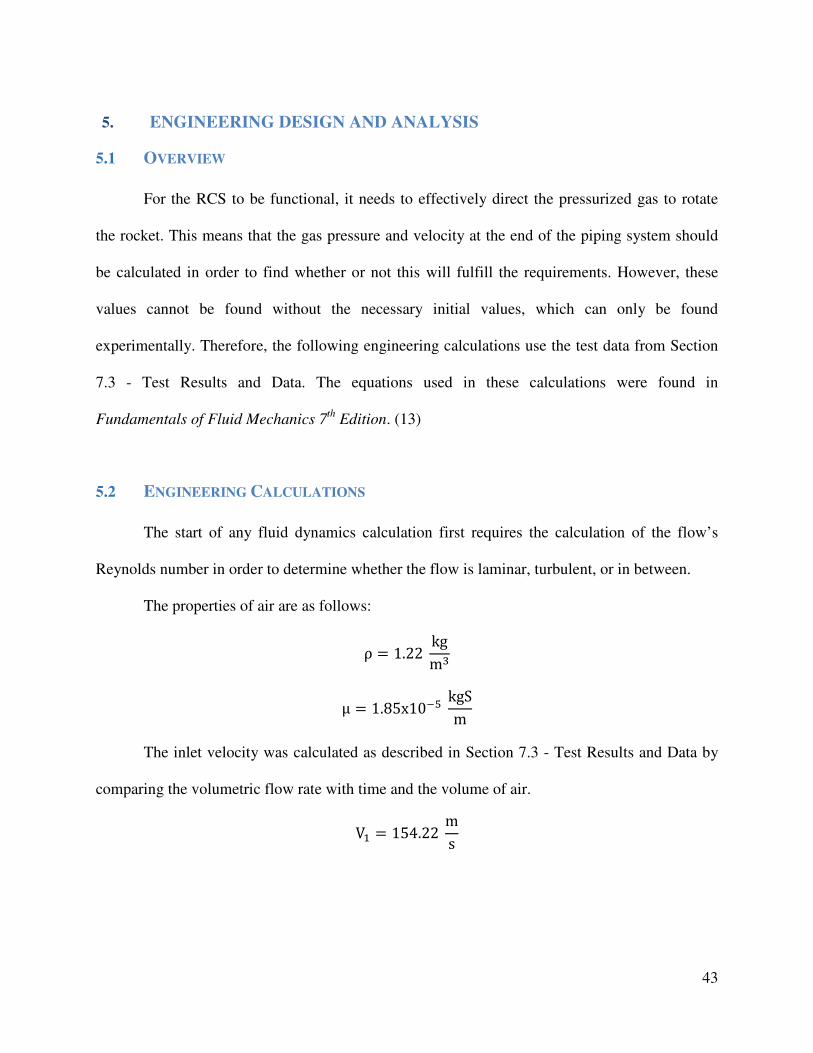
5.2 ENGINEERING CALCULATIONS
The start of any fluid dynamics calculation first requires the calculation of the flow’s
Reynolds number in order to determine whether the flow is laminar, turbulent, or in between.
The properties of air are as follows:
ρ = 1.22 kgm
μ = 1.85x10�� kgSm
The inlet velocity was calculated as described in Section 7.3 - Test Results and Data by
comparing the volumetric flow rate with time and the volume of air.
V� = 154.22ms

44
The cross-sectional area of the inlet pipe is D = 0.00635 m, which means that the area,
A = 0.00635 m2. With these values, the Reynolds number can now be calculated.
Re = ρVDμ =�. �� ���� ∗ �!". ���# ∗ $. $$%�!&
�. '!(�$�! ���#= 64,580.7
The next step is to find the inlet pressure:
P = -./0 =
�.00 1234∗��5.00360 = 14507.6 7
8/ = 14.59:;
In order to find the outlet velocity, the major and minor losses are first ignored.
Q1 = Q2 + Q3
Q1 = A2V2 + A3V3
V3 = V2 = <=0∗> = 77.109 m/s
Now the major and minor losses can be taken into account in order to find a more
realistic value for the outlet velocity.
p�γ +V�
0
2g + Z� =p0γ +V�0
0
2g + Z0 + Cf lD + ΣKHI V00
2g
First, the major losses were found. Major losses are due to friction in the pipe, though this
factor is expected to be small compared to the minor losses due to the relative shortness of the
piping involved.
hHK>LMN = f OP
.//0Q (Eq. 8.34) (13)
R = 0.6096m D = 0.00635 m
The equivalent roughness value used was that of a commercial steel pipe: ε = 4.5e-5 m.
(Table 8.1) (13)

45
The Re & TP relative roughness on Moody’s Chart (Figure 8.20) (13) were used to
approximate the friction factor, U = 0.035.
The minor losses were then calculated.
hHKW7MN = ΣKH.//0Q (Eq. 8.36) (13)
The following parts and their associated loss factor coefficients were found in Table 8.2:
Table 1 – Minor Loss Coefficients
Part Quantity Associated Loss
90˚ Threaded Elbows 3 XY = 3 ∗ 1.5 = 4.5
Tee Branched Flow, Threaded 1 XY = 2.0
45˚ Flanged Elbows 2 XY = 2 ∗ 0.2 = 0.4
Afterwards, Bernoulli’s equation can be used to find the major and minor head loss, as
long as we assume that there is no significant change in height and that the compressed air exits
into the atmosphere:
Z1 = Z2 = 0 P2 = 0 γ = 11.81 784
p�γ +V�
0
2g = V00
2g + Cf lD + ΣKHI V00
2g
�5�Z[.�\ ]3/��.^� ]34
+ _��5.0036 `
/
0∗_a.^�36/` = [
�0∗_a.^�36/`
+ Z.Z�∗Z.\Za\8
Z.ZZ\�8∗0∗_a.^�36/` +
\.a0∗_a.^�36/`
]*V00
b0 = 65.20c/e Therefore, the exit velocity was found to be 65.50 m/s.
46
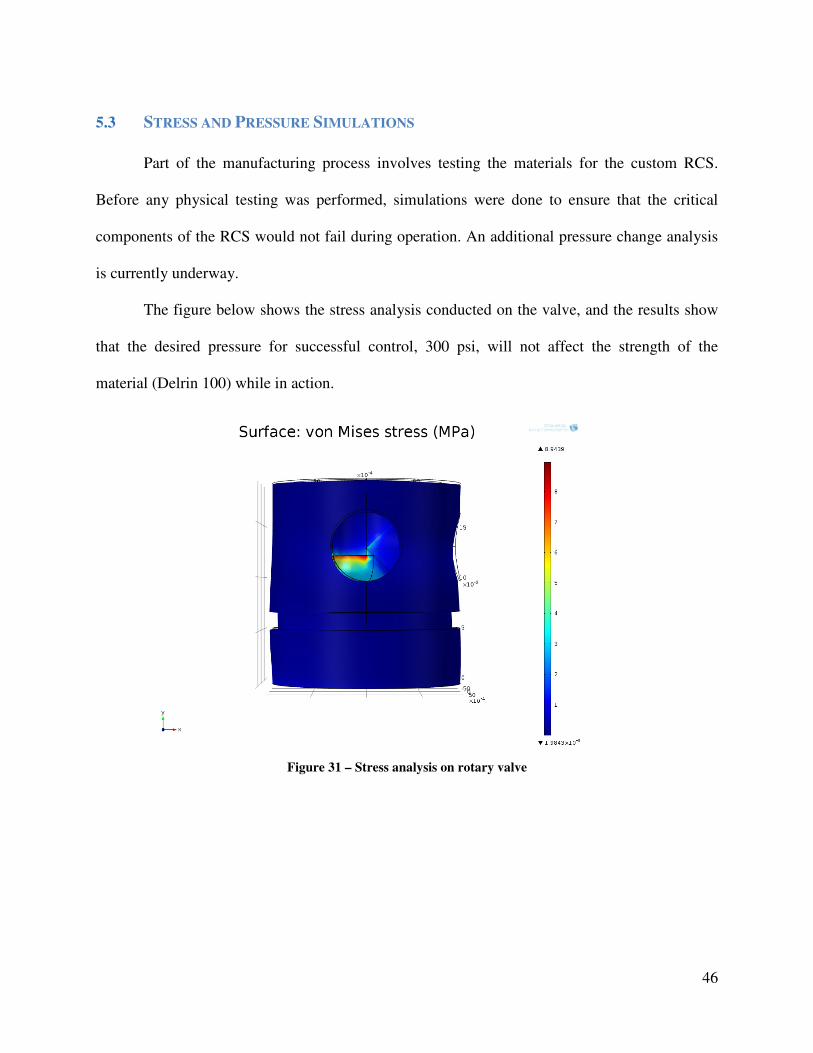
5.3 STRESS AND PRESSURE SIMULATIONS
Part of the manufacturing process involves testing the materials for the custom RCS.
Before any physical testing was performed, simulations were done to ensure that the critical
components of the RCS would not fail during operation. An additional pressure change analysis
is currently underway.
The figure below shows the stress analysis conducted on the valve, and the results show
that the desired pressure for successful control, 300 psi, will not affect the strength of the
material (Delrin 100) while in action.
Figure 31 – Stress analysis on rotary valve

47
Because our valve was designed with a 90° bend to supply the exit ports, some loss in
pressure will be inevitable. Our initial assumption of 300 PSI will not satisfy the required force
per exit nozzle to orient the rocket at the desired attitude. According to our simulations, higher
inlet pressures will need to be calculated to satisfy the mission requirements of 9 lbf (40 N) per
nozzle.
Figure 32 – Pressure simulation for valve channel

48
5.4 COST ANALYSIS
Rapid prototyping the RCS in titanium by selective laser melting (SLM) was estimated
by NASA to cost $413.74. The NEMA 17 stepper motor required to turn the rotary valve will
cost $24.95. The input valve, as previously mentioned, will cost $363. The Swagelok piping is
estimated to cost around $150. A scuba tank system is currently owned by one of the team
members, saving the cost of purchasing a new one. This leaves the current running total as
$951.69 at the current design iteration. Future changes to the design, however, will increase the
cost, since the new pieces will have to be produced.

49
6. PROTOTYPE CONSTRUCTION
6.1 PROTOTYPE SYSTEM DESCRIPTION
The prototype system will consist of:
• 540 Steel 3D printed valve and manifold assembly
• Swagelok pipe fittings
• Swagelok 0.245 inch ID pipes
• 750 PSI supply from paintball gun tank system
• NEMA 17 motor for turning the valve
The system will be connected to a 3D printed shroud to provide support and ports for the
tubes coming out of the manifold. This system will then be hung vertically to test the
translational and rotational effects of the RCS. Thrust capacity will be measured while the
system is fixed on a scale and compared to the angular maximum reached during the vertical
hang testing.

50
6.2 COMPLETED PROTOTYPE DESIGN
Figure 33 shows all three prototypes of the valve; the right-most being the current one.
The current design maintains the ¼” flow diameter but decreases the diameter to 1.9” and height
to 1.375”. The current prototype is 3D printed in 540 steel.
Figure 33 – The three prototypes together
The current prototype setup can be seen below.
Figure 34 – Assembled Prototype

51
6.2.1 VALVE AND MANIFOLD
Two gas delivery systems are tested. The first uses ¼” OD piping from the tank to the
Parker Series 9 on/off solenoid valve. Although the ID of the pipe is 0.142” (half our desired
size), it has to pass through the 1/32” orifice of the Parker valve which becomes a bottleneck.
The second gas delivery system consists of ¼” ID tubing throughout, but without an
on/off valve, thereby eliminating the 1/32” orifice bottleneck. The tank will be turned on and off
manually for this test. This is to measure the output capable when suitable flow control is
acquired, since valves capable of controlling this volume are priced beyond the funding limit of
this project.
6.2.2 PIPING ARANGEMENT
The pipes purpose is to get the air pressure from the tank to the on/off valve, from the
on/off valve to the RCS valve, and then from the RCS valve to the exterior of the craft. For our
tests, the pipe routing is as simple as possible with the simple purpose of allowing us to test air
flow through the RCS valve. The actual routing system on the Nanolaunch will be determined
once the vehicle is further along in the design process.

52
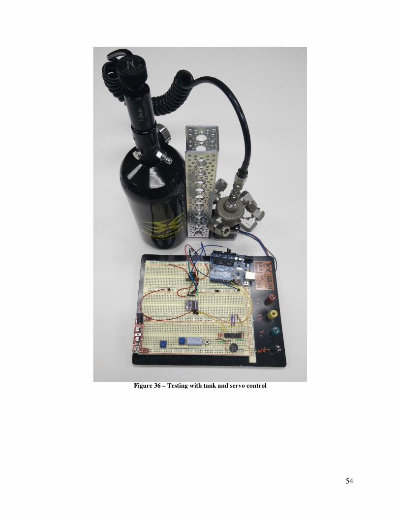
6.2.3 TESTING APPARATUS
Our current testing device consists of a direct flow of air from the tank to the RCS valve.
The RCS valve, air tank, stepper motor, and a potentiometer are mounted on aluminum
C-channel which is, in turn, mounted on an aluminum shaft with pillow bearings to allow
rotation. When the tank is opened, the RCS system rotates on the shaft. The potentiometer is
included to provide a feedback loop signal on the position of the valve.
An Arduino Uno controls the position of the valve using the potentiometer value. It then
sends a control signal to a stepper motor driver to turn the valve until the potentiometer signal
returns the desired value. The stepper motor is powered by a 12V regulator, and both the
Arduino and the stepper driver are powered by a 5V regulator. This testing device is being
further developed to include the on/off valve, steel piping, tank straps, on-board electronics, and
a battery.

53
Figure 35 – Final Test Setup
54
Figure 36 – Testing with tank and servo control

55
6.3 PARTS LIST
Table 2 – Complete List of Parts Used
Quantity Part Supplier Cost
1 DRV8825 Stepper Motor Driver Pololu $ 8.95 2 Pololu Stamped Aluminum L-Bracket Pololu $ 7.90 1 NEMA 17 Stepper Motor Amazon $ 16.70 1 DC-DC 12v Step down converter Amazon $ 7.95 1 3/8-24 to 1/4" NPT SS Adapter Amazon $ 19.95 1 3/8" Tube x 1/4" NPT Ebay $ 8.25 1 1/4" Tube x 1/8" NPT Ebay $ 7.95 1 3/8" OD Steel Tube Ebay $ 12.86 1 3/8" Tube x 1/4" NPT Ebay $ 7.95 1 1/4" OD Steel Tube Ebay $ 4.98 4 3/8" Tube x 1/4" NPT 90 Bend Ebay $ 35.80 1 3/8" Tube x 1/4" NPT Ebay $ 8.25 1 1/4-18 NPT Tap Ebay $ 27.00 1 12mm OD 6mm ID Steel Thrust Bearing McMaster-Carr $ 16.01 1 1/4 inch x 2.00 inch D-Shaft Servocity $ 1.49 1 1 inch Smooth Hub Servocity $ 5.99 1 3/8 inch Bore Parallel Tube Clamp Servocity $ 5.99 1 Surface Mount Adaptor A Servocity $ 3.99 1 3 inch ID x 1/8 inch Smooth Belt Servocity $ 0.59 1 2.5 inch ID x 1/8 inch Smooth Belt Servocity $ 0.49 1 3.5 inch ID x 1/8 inch Smooth Belt Servocity $ 0.69 1 Single Header Row Pins Servocity $ 1.49 1 Dual Screw Plate (2 pack) Servocity $ 2.99 4 4-40x1/4 inch Flat Head Screws Servocity $ 0.12 4 6-32x1/4 inch Flat Head Screws Servocity $ 0.15 4 4-40x5/16 inch Socket Head Screws Servocity $ 0.35 4 4-40x3/8 inch Socket Head Screws Servocity $ 0.35 1 Crossover Plate A Servocity $ 5.99 1 1/4 inch to 5mm Set Screw Shaft Coupler Servocity $ 4.99 2 Rubber Edge Trim Servocity $ 0.89 1 Shipping Servocity $ 6.99 1 48 CU Compressed Air Tank Splat Attack $ 50.00 1 Manual Valve & Hose Splat Attack $ 45.00 1 Acrylic Rod Ebay $ 26.00 1 3D SS Valve & Manifold Shapeways $ 171.09
Total $526.13

56
6.4 PROTOTYPE COST ANALYSIS
Some of the parts purchased did not end up being used, adding to the total cost of first
prototype. The cost of the Senior Design I poster was also included in Table 3 in order to tally
the total amount spent on this project, which was $674.60. Considering that the four valves
required for NASA’s version of the RCS cost $1452, even with the additional costs our project
still turned out at less than half the price, especially since NASA’s RCS price must be still higher
when including the piping and other components. Therefore, this project can be considered a
great success in terms of reducing the price of the system, as even 3D-printing in titanium rather
than stainless steel should still keep the cost of our product below that of NASA’s original
prototype.

57
Table 3 – Complete List of Parts Purchased
Quantity Part Supplier Cost
1 DRV8825 Stepper Motor Driver Pololu $ 8.95 2 Pololu Stamped Aluminum L-Bracket Pololu $ 7.90 1 NEMA 17 Stepper Motor Amazon $ 16.70 1 DC-DC 12v Step down converter Amazon $ 7.95 1 3/8-24 to 1/4" NPT SS Adapter Amazon $ 19.95 1 3/8" Tube x 1/4" NPT Ebay $ 8.25 1 1/4" Tube x 1/8" NPT Ebay $ 7.95 1 3/8" OD Steel Tube Ebay $ 12.86 1 3/8" Tube x 1/4" NPT Ebay $ 7.95 1 1/4" OD Steel Tube Ebay $ 4.98 4 3/8" Tube x 1/4" NPT 90 Bend Ebay $ 35.80 1 3/8" Tube x 1/4" NPT Ebay $ 8.25 1 1/4-18 NPT Tap Ebay $ 27.00 1 2" Clear acrylic rod Ebay $ 14.00 1 1-1/4" Delrin Rod Ebay $ 8.04 1 Parker 9-series Valve Ebay $ 50.00 1 12mm OD 6mm ID Steel Thrust Bearing McMaster-Carr $ 16.01 1 1/4 inch x 2.00 inch D-Shaft Servocity $ 1.49 1 1 inch Smooth Hub Servocity $ 5.99 1 3/8 inch Bore Parallel Tube Clamp Servocity $ 5.99 1 Surface Mount Adaptor A Servocity $ 3.99 1 3 inch ID x 1/8 inch Smooth Belt Servocity $ 0.59 1 2.5 inch ID x 1/8 inch Smooth Belt Servocity $ 0.49 1 3.5 inch ID x 1/8 inch Smooth Belt Servocity $ 0.69 1 Single Header Row Pins Servocity $ 1.49 1 Dual Screw Plate (2 pack) Servocity $ 2.99 4 4-40x1/4 inch Flat Head Screws Servocity $ 0.12 4 6-32x1/4 inch ; Flat Head Screws Servocity $ 0.15 4 4-40x5/16 inch Socket Head Screws Servocity $ 0.35 4 4-40x3/8 inch Socket Head Screws Servocity $ 0.35 1 Crossover Plate A Servocity $ 5.99 1 1/4 inch to 5mm Set Screw Shaft Coupler Servocity $ 4.99 2 Rubber Edge Trim Servocity $ 0.89 1 Shipping Servocity $ 6.99 1 48 CU Compressed Air Tank Splat Attack $ 50.00 1 Manual Valve & Hose Splat Attack $ 45.00 1 Acrylic Rod Ebay $ 26.00 1 3D SS Valve & Manifold Shapeways $ 171.09 1 Senior Poster FIU $ 60.00
Total $ 674.60

58
7. TESTING AND EVALUATION
7.1 OVERVIEW
Extensive ground tests will be carried out on the RCS before subjecting it to a flight test
on an amateur rocket. The valve, manifold, and fittings will first be assembled and tested to
ensure the required minimum force of 10 N is produced. Our calculations estimate a theoretical
force of 82 N with 375 PSI at the nozzle. Using commercial hobby valves, a maximum nozzle
pressure of 575 PSI is possible should more force be needed, equating to 125 N. The required
longevity of the RCS system in terms of actuations is not yet established in the requirements.
Once those guidelines are available, the maximum pressure to meet the requirements can be
estimated, and then tested. The governing limitation will be gas supply. The estimated life of the
system is approximately 10 minutes. After this elapsed time the payload will have separated and
the rest of the vehicle will burn up in the atmosphere.
The second stage of prototype testing will then commence, consisting of mounting the
prototype in an amateur rocket with an internal 6 inch (15.2 cm) diameter.
The amateur rocket, designated “Nanolaunch 1D,” will be flown by NASA once the
valve has proven successful in ground tests. The tank used will be a similar setup to the NASA
test rig shown in Figure 37.

59
Figure 37 – Current NASA RCS Prototype

60
7.2 DESIGN OF EXPERIMENTS
Several experiments were set up in order to test the following:
• The rotation of the inner valve inside the manifold
• The stepper motor’s control of the rotating valve
• The air flow through the valve
• The positive rotation of testing apparatus with activation of flow
The rotation of the inner valve within the manifold required high tolerance machining of
the 3D printed parts. If the tolerances were off, the inner valve would freeze, wobble, or leak out
air. The fit was continuously tested and machined, until the desired tolerances and performance
were achieved.
The RCS valve was then mounted along with a stepper motor to ensure the stepper had
enough torque to rotate the valve and that the shafts were aligned. This testing showed there was
little tolerance in the positioning of the stepper and RCS valve. If slightly the measurements were
off, the inner valve would seize in place. One way to ameliorate this issue would be to add a
universal joint so that vibrations in the vehicle wouldn’t cause temporary seizure of the inner
valve.
The air flow was then tested by connecting the tank directly to the RCS valve. This test
showed the system was air-tight. The O-rings inside the RCS valve worked as expected. The
tolerances for their fit are accurate and allow the O-rings to withstand the pressure.
The rotation of the apparatus was then tested by allowing the air flow to rotate the
apparatus. This test ensured the system was free to move and that the RCS valve produced thrust.
Further development of the system will have all associated elements on the rotating structure,
such as an on/off valve, control electronics, and a power supply.

61
7.3 TEST RESULTS AND DATA
The rotation of the RCS during testing showed that the machining was accurate and the
assembly worked, as the stepper motor was able to smoothly rotate the valve between positions,
which would allow it to switch which channels were open and thereby perform the desired
maneuvers once mounted on a craft. These demonstrations were recorded for use in the product
presentation and can unfortunately not be shown in the static medium of this report.
In order to calculate the expected pressure and air velocity at the outlet of the RCS, after
all of the minor and major losses due to the piping, a simple test was conceived and executed to
determine the volumetric output of the pressurized tank. Balloons were attached to the outlet of
the pressurized tank, and a short burst of gas was allowed to fill the balloon. The time allowed
for the burst was measured with a stopwatch, and the volume of the air captured in the balloon
was then calculated by submerging the balloon in a tank and calculating the displacement of the
water. Three trials were performed to minimize the experimental error due to the human factors,
including reaction time and measurement errors. The volumetric flow rate of the tank was
estimated to be 0.172 ft3/s (4883.9 cm3/s, ~ .005 m3/s).
While not extremely precise, these measurements are enough to give a good idea of what
values to use for Section 5.2 - Engineering Calculations. A Pitot tube could not be used in this
case because of the turbulent nature of the high-pressure flow, and other measurement tools, such
as rotating vane anemometers, are more suited to smaller airflows, and therefore inappropriate
for this type of measurement.

62
8. DESIGN CONSIDERATIONS
8.1 ASSEMBLY
The assembly of the RCS system is a fairly simple process once all the parts have been
obtained and the valve and manifold are complete. All that is required then is to attach the tubes
and pipe fittings correctly in order to have a fully functional system.
8.2 DISASSEMBLY AND MAINTENANCE
The nature of the missions for which the Nanolaunch initiative is designated means that
the rocket launches are one-way only. Once the P-POD cargo has been jettisoned from the craft,
the RCS will join the rest of the rocket and the previous rocket stages in disintegrating into the
atmosphere. Therefore, no disassembly or maintenance would need to be taken into
consideration for the design of the RCS.

63
8.3 ENVIRONMENTAL IMPACT
Rockets, whether they use solid or liquid fuel, inevitably discharge ozone-depleting
substances into Earth’s atmospheres, though liquid fuel may be less damaging. (14) However,
the amount of greenhouse gases released by rocket launches is still almost negligible compared
to that of aircraft, which actually only makes up a whopping 2-5% of the world’s CO2 emissions.
(15) Therefore, this source of greenhouse gases can be ignored in favor of concentrating on
bigger offenders, though the projected increases in rocket launches may require more attention in
the future. (14) The proposed RCS design helps prevent the use of alternate RCS designs (such
as Vernier rockets) that require additional fuel (and therefore pollution) in order to turn the
vehicle.
The aforementioned atmospheric disintegration of the RCS will contribute to the
collection of orbital debris circling the Earth’s atmosphere. (16) However, this is an unfortunate
and currently unavoidable consequence of this type of mission.
64
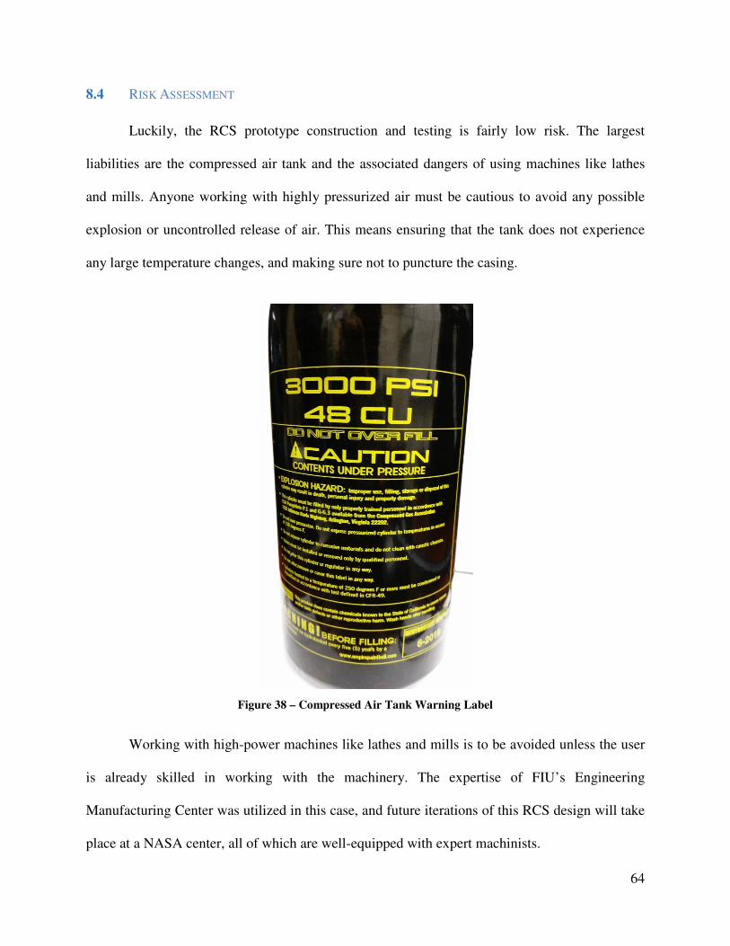
8.4 RISK ASSESSMENT
Luckily, the RCS prototype construction and testing is fairly low risk. The largest
liabilities are the compressed air tank and the associated dangers of using machines like lathes
and mills. Anyone working with highly pressurized air must be cautious to avoid any possible
explosion or uncontrolled release of air. This means ensuring that the tank does not experience
any large temperature changes, and making sure not to puncture the casing.
Figure 38 – Compressed Air Tank Warning Label
Working with high-power machines like lathes and mills is to be avoided unless the user
is already skilled in working with the machinery. The expertise of FIU’s Engineering
Manufacturing Center was utilized in this case, and future iterations of this RCS design will take
place at a NASA center, all of which are well-equipped with expert machinists.
65
9. DESIGN EXPERIENCE
9.1 OVERVIEW
This project was a learning experience for all of the team members involved. There were
several unanticipated delays that impacted the development of the project, including the
extension of the 3D-printing production time by a week. This was a cascading issue, since all of
the assembly and testing depended on the valve and manifold being complete. The team
members also developed new appreciation for the safety, standards, and global considerations
during the conception, assembly and testing of the RCS. These practical lessons will be
invaluable experiences for our future careers as professional mechanical engineers.
9.2 STANDARDS USED IN THE PROJECT
Standards, codes, specifications, and technical regulations must be an essential part of
every engineering project in order to ensure the safety and reliability of the final product. At the
component level, the Nanolaunch rocket must conform to the Tripoli Rocketry Association
(TRA) and National Association of Rocketry (NAR) regulations. (1)(2)(3) At the component
level, all the pipes and fittings used have to conform to the National Pipe Thread Taper (NPT)
standards (4), which are defined by ANSI/ASME Standard B1.20.1. The motor driver must
follow American National Standards Institute (ANSI) and National Electrical Manufacturers
Association (NEMA) standards (5), and the cap screws must conform to American Society for
Testing and Materials (ASTM) standards (6). The paint-ball tank must also follow the
Committee of Federal Register’s (CFR) requirements for portable tanks in order to allow for safe
transportation (7).

66
9.3 IMPACT OF DESIGN IN A GLOBAL AND SOCIETAL CONTEXT
The development of an economical RCS for small rockets will have a tremendous impact
on the advancement of space and earth sciences worldwide. The Nanolaunch will allow more
universities and research institutions to launch experiments and observational satellites into Earth
orbit. Many earth sciences and conservation efforts, including geology, water management, and
forest conservation, rely on imaging and readings from orbit in order to obtain the large-scale
datasets needed. Initiatives like the Nanolaunch will allow for more research of this type, which
can lead to the development of efforts to improve and restore the Earth’s environment.
9.4 PROFESSIONAL AND ETHICAL RESPONSIBILITY
As engineers, it is essential to recognize our duties to the global community and ensure
the public good to the best of our abilities. It is our hope that our RCS can lead to an increase in
research in the aerospace and earth sciences, and that our system can open the doors to orbital
research to smaller universities and institutions that have not historically had the opportunity to
participate in these expense-heavy topics. We have also made sure that the system has little risk
of causing injury, aside from the natural risk of working with compressed gases.

67
9.5 LIFE-LONG LEARNING EXPERIENCE
Designing and producing this reaction control system has been a highly interesting
experience that has cemented our love of engineering. This process has shown us the intricacies
of taking a concept, however simple it may be at its core, to functionality, and the many
challenges that arise in doing so. The team members have definitely developed respect for the
amount of effort required for such endeavors and for the real-world factors that can intrude,
including shipping delays, ordering wrong parts, and tight tolerances to meet.
At the same time, the process was invigorating, because the final product is one that can
be used by others in the real world. This is a taste of the real engineering work life, where
products need not only to be designed, but also tested, troubleshot, presented, corrected and
improved. 3D printing also turned out to be a major advantage in the construction of the part, and
it is exciting to think about which future technologies may impact the manufacturing process in
the future. To be a successful engineer, it is essential to remain abreast of new developments in
the field, especially those that will affect the design and production of your projects. This is no
chore, however, as it is a pleasure to see how technology improves and facilitates the
development of increasingly intricate, tiny and complex machinery.

68
10. CONCLUSION
10.1 CONCLUSION AND DISCUSSION
The proposed RCS design under development for use in NASA’s Nanolaunch initiative is
very promising. It should turn out to be cheaper and more reliable than the current mechanism in
testing, primarily due to its reduction of necessary input valves. Further work is needed to
produce a working physical prototype for testing so that the results can be used in the next
iteration of the design until the product has reached all of its objectives in terms of reliability,
performance, and low cost. If successful, this project will make space more accessible for the
academic and scientific community for learning and experimentation purposes.
10.2 COMMERCIALIZATION PROSPECTS OF THE PRODUCT
Due to the scalability of this rotary valve system, it can be applied to a plethora of
applications. Other uses of the valve can include pharmaceutical production or any other industry
where distribution of a fluid (including gases) is required. This rotary valve can be modified to
include more port combinations (including multiple inputs) instead of just the four outlined in
this report.

69
10.3 FUTURE WORK
Further development of the RCS valve system will reduce volume and mass to allow for
more versatile allocation within the Nanolaunch shroud. The current design has a wide base
required for installation of the 1/4” NPT to 3/8” tube fittings. The final version, however, could
have the tubes welded directly onto the manifold, reducing the maximum diameter of the
manifold from 1.9” to 1” (4.8 cm to 2.5 cm) and the height from 1.375” to 0.97” (3.5 cm to 2.5
cm) as shown below in Figure 39.
The 420 stainless steel 3D printing cost of the weld-ready manifold is only $35 versus
$159 for the fittings version. This also eliminates over $45 worth of fittings. Torque testing of
the valve could also lead to a smaller stepper motor such as a NEMA 8 rather than a 17.
Figure 39 – Weld-ready valve on the left
The valve is the limiting factor of RCS thrust capability. The type of on/off valve system
for the gas propellant supply can also be further investigated to find a solenoid valve capable of a
much larger volume (larger orifice) or a linear valve controlled by a stepper motor that can exert
fine control over the gas release and hence, the vehicle response.

70
Figure 40 – Various types of on/off valves that could be used

71
11. REFERENCES
1. Mahoney, E. (n.d.). CubeSat Launch initiative (CSLI). Retrieved September 20, 2014, from
http://www.nasa.gov/directorates/heo/home/CubeSats_initiative.html
2. NASA. (n.d.). About the nano-satellite launch challenge. Retrieved from
http://www.nasa.gov/offices/oct/early_stage_innovation/centennial_challenges/nano_satellit
e/nano_overview_prt.htm
3. Dunbar, B. (2014, September 4). ELaNa. Retrieved October 20, 2014, from
http://www.nasa.gov/mission_pages/smallsats/elana/
4. Frederick, R. (2014, FEB 10). Charger rocket works designing new rocket for NASA
competition challenge. Retrieved from http://www.uah.edu/news/research/7317-charger-
rocket-works-designing-new-rocket-for-nasa-competition
5. Sidi, M. J. (1997). Spacecraft dynamics and control: a practical engineering approach
(Vol. 7). Cambridge University Press.
6. Apfel, S. L. (1989). U.S. Patent No. 4,880,185. Washington, DC: U.S. Patent and
Trademark Office.
7. Chobotov, V. A. (1991). Spacecraft attitude dynamics and control. NASA STI/Recon
Technical Report A, 92, 40900.
8. Wertz, J. R. (Ed.). (1978). Spacecraft attitude determination and control (Vol. 73).
Springer.
9. Dumoulin, J. (n.d.). Reaction Control System. Retrieved September 20, 2014, from
http://science.ksc.nasa.gov/shuttle/technology/sts-newsref/sts-rcs.html
10. Carson, D. B. (1962). U.S. Patent No. 3,040,777. Washington, DC: U.S. Patent and
Trademark Office.

72
11. Gamble, R. L., & Stewart, R. D. (1985). U.S. Patent No. 4,536,121. Washington, DC: U.S.
Patent and Trademark Office.
12. Tailor, J. P. (1964). U.S. Patent No. 3,151,784. Washington, DC: U.S. Patent and Trademark
Office.
13. Munson, B. R., Rothmayer, A. P., Okiishi, T. H., & Huebsch, W. W. (2012). Fundamentals
of fluid mechanics. Seventh Edition. Wiley.
14. Ross, M., Toohey, D., Peinemann, M., & Ross, P. (2009). Limits on the space launch market
related to stratospheric ozone depletion. Astropolitics, 7(1), 50-82.
15. Jardine, C. N. (2009). Calculating the carbon dioxide emissions of flights. Final report by the
Environmental Change Institute.
16. Rossi, A., Cordelli, A., Farinella, P., & Anselmo, L. (1994). Collisional evolution of the
Earth's orbital debris cloud. Journal of Geophysical Research: Planets (1991–2012),
99(E11), 23195-23210.

73
12. IMAGE CREDITS
17. Dunbar, B. (2006, July 19). Bigelow Spacecraft Carries NASA 'GeneBox' to Orbit. Retrieved
October 20, 2014, from
http://www.nasa.gov/centers/ames/multimedia/images/2006/genebox_prt.htm
18. Benson, T. (n.d.). Rocket Control. Retrieved September 20, 2014, from
http://microgravity.grc.nasa.gov/education/rocket/rktcontrl.html
19. Wolfe, J. (n.d.). Brass instrument (lip reed) acoustics: An introduction. Retrieved October 14,
2014, from http://newt.phys.unsw.edu.au/jw/brassacoustics.html

74
13. APPENDICES
13.1 APPENDIX A: DRAWINGS

75

76
13.2 APPENDIX B: PROOF OF PROJECT PRODUCTION STATUS
Figure 41 – Shapeways Receipt

77
13.3 APPENDIX C: ORIGINAL SWAGELOK QUOTE

78
79
13.4 APPENDIX D: STANDARDS, CODES, SPECIFICATIONS AND TECHNICAL REGULATIONS
1. "TRA High Power Safety Code". Tripoli Rocketry Association.
2. “NAR High-Power Certification Procedure". National Association of Rocketry.
3. "CAR Certification". Canadian Association of Rocketry.
4. “ASME Standards”. American Society of Mechanical Engineers.
5. “ANSI Standards”. American National Standards Institute.
6. “ASTM Standards”. American Society for Testing and Materials.
7. “CFR Standards”. Committee of Federal Register.

80
13.5 APPENDIX E: RAW DATA FROM VOLUMETRIC FLOW EXPERIMENT
Table 4 – Volumetric Flow Rate Experimental Data
Start Trial 1 Trial 2 Trial 3 Average
Time of Gas Release(s) 0.35 0.36 0.31 0.34
Water Depth (cm) 10.1 12.85 13.45 12.65 13.0
Radius of Bucket @Water Height (cm) 12.6 12.7 12.6 12.6
Total Volume (cm3) 3543.3 5142.5 5417.3 5051.8 5203.9
Air Volume (cm3) 0 1599.2 1874.0 1508.5 1660.5
Volumetric Flow Rate of Tank (cm3/s) 4569.1 5205.5 4866.0 4883.9


![Satellite Attitude Control Using Three Reaction Wheels · Satellite attitude control using three reaction wheels ... [12]. A reaction wheel is a device that applies torque ... The](https://img.pdfslide.us/doc/110x75/5b885d727f8b9abf5c8b699b/satellite-attitude-control-using-three-reaction-satellite-attitude-control-using.jpg)