Embed Size (px)
Citation preview

International Journal of Solids and Structures 43 (2006) 1505–1527
www.elsevier.com/locate/ijsolstr
Nanoindentation of Pb/Sn solder alloys; experimentaland finite element simulation results
Juan Gomez, Cemal Basaran *
UB Electronic Packaging Laboratory, Civil Engineering Department, State University of New York at Buffalo,
212 Ketter Hall, Buffalo, NY 14260, United States
Received 22 November 2004; received in revised form 1 June 2005Available online 18 October 2005
Abstract
A thermodynamics based damage mechanics coupled constitutive model is used to simulate the nanoindentationexperiment on eutectic commercial Pb/Sn solder alloys. The study is aimed at explaining the apparent size dependentbehavior observed at small indentation depths for this class of highly rate dependent materials. Interest is at smalldepths of indentation and a small-strains small-displacements theory is used. The study is motivated by the fact, thatin the case of rate independent materials such a size dependence of the response is explained in terms of storage of theso-called geometrically necessary dislocations. Presently it is not clear if this is the source of size effects in a rate depen-dent material. Moreover, the storage of dislocations is difficult in eutectic solder alloys due to thermally activated dif-fusion processes that promote dislocation mobilization as opposed to storage. Therefore, a classical theory constitutivemodel should be able to capture such a size dependent feature of the response. The paper describes the constitutivemodel and its integration scheme. Simulations of the nanoindentation problem are performed at different temperaturesand indentation strain rates and numerical results are compared with experiments.� 2005 Elsevier Ltd. All rights reserved.
Keywords: Finite element analysis; Constitutive model; Nanoindentation; Damage mechanics; Solder alloys
1. Problem statement
Eutectic solder alloys are widely used in the microelectronics industry. They are intended to provideelectrical, thermal and mechanical continuity to the package and therefore are highly important for the
0020-7683/$ - see front matter � 2005 Elsevier Ltd. All rights reserved.doi:10.1016/j.ijsolstr.2005.06.095
* Corresponding author. Tel.: +1 716 645 2114x2429; fax: +1 716 645 3733.E-mail address: [email protected] (C. Basaran).
1506 J. Gomez, C. Basaran / International Journal of Solids and Structures 43 (2006) 1505–1527
reliability of the system. Furthermore, they are routinely used at high homologous temperatures, being at0.65Tm at room temperature (where Tm represents the material melting point) exhibiting considerable time,temperature and stress dependent response and making its constitutive modeling a difficult task. On theother hand the nanoindentation technique is frequently used to measure material properties for solder al-loys and other material at small volumes. In fact, this technique has gained popularity as an experimentaltool to determine the material properties for specimens available in small volumes. Results from nano-indentations experiments on rate independent materials have shown a strong dependence of hardness onthe penetration depth (Stelemashenko et al., 1993; Ma and Clarke, 1995; Poole et al., 1996). A similar re-sponse is identified in the case of Pb/Sn solders, which in contrast are highly rate dependent even at roomtemperature. The character and relevance of this size dependent response in the case of rate dependentmaterials has not been addressed either theoretically or experimentally. The source of additional resistancein the case of rate independent materials has been recognized as due to the presence of additional disloca-tions needed to accommodate strong gradients of plastic strain (Fleck et al., 1994; Fleck and Hutchinson,1997; Gao et al., 1999). However, the fact that solder alloys operate very close to the material melting pointprecludes the storage and trapping of additional dislocations like an explanation to the observed size effect.This suggests that in the case of Pb/Sn solder alloys the observed size dependence is not related to storage ofadditional dislocation densities but to the viscoplastic character of the material itself and therefore it shouldbe observed from simulations with a proper rate dependent model without any intrinsic material lengthscale. In this paper we make a first attempt to study the response of eutectic solder alloys in a range of smalldepth penetrations where a small-strains small-displacements viscoplastic theory is used. This is exactly thesame approach used by Shu and Fleck (1997), Begley and Hutchinson (1998), Huang et al. (2000) and Xueet al. (2002a,b) where small-scale indentation problems were addressed using finite element simulations andsmall-strains small-displacements assumptions. This can constitute a source of minor errors due to the self-similar character of the deformations being imposed in the case of a sharp Berkovitch indenter. The effect ofthe sharp tip translates into large rotations near the perfectly sharp tip. However as we will show subse-quently, a classical theory constitutive model without the addition of any material length scale (or storageof geometrically necessary dislocations) still captures an apparent size effect. The current work is dividedinto two major parts. First we present a unified creep-plasticity framework directly derived to describethe behavior of Pb/Sn solder alloys. The model itself is the one derived previously by Basaran and Yan(1998); however we have implemented the constitutive equations into a different integration scheme whichallows the model to be used in 3D and axisymmetric problems. Previous implementations of the model(Basaran and Tang, 2002; Tang, 2002) were restrained to plane strain idealizations, thus limiting its rangeof applicability. Details of the model, integration scheme and previous verifications are included in the pres-ent article. The second part of the work deals with the numerical modeling of the nanoindentation problembut restrained at the small-scale response. This is intended to compare our results with similar simulationsas discussed above. Although it is only possible to perform nanoindentations at room temperature, we havetaken advantage of our model to simulate the ‘‘nanoindentation’’ experiment at other temperatures andgain further insight into the apparent indentation size effect. Finally, we want to point out that in factin the particular case of the nanoindentation problem where loading is in one direction, the effect of damageis irrelevant. We have included the damage formulation and corresponding coupling into the model equa-tions in order to describe the full capabilities of the framework. Moreover, it should become clear that dam-age as treated in this work is relevant for problems under cycling loading conditions. This is the case of theinduced low cycle fatigue caused by the coefficient of thermal expansion mismatch between the differentparts bonded by Pb/Sn solder joints.
The article is organized as follows; Section 2 presents a literature survey about constitutive modeling ofsolder alloys and of previous indentation models, including a discussion about the small-scale indentationproblem. Section 3 describes the constitutive model, its integration scheme and shows results corresponding

J. Gomez, C. Basaran / International Journal of Solids and Structures 43 (2006) 1505–1527 1507
to a verification study where numerical simulations are compared with experiments under a wide range oftemperatures and strain rates. Section 4 describes the numerical simulation of the nanoindentation exper-iment with analysis of results and conclusions given in the final section.
1.1. Notation
Tensorial (indicial) and matrix notation are used throughout this article. In matrix notation second or-der tensors will be mapped into column vectors and fourth order tensors will be mapped into matrices. Inindicial notation repeated indices are assumed to follow the summation convention unless explicitly statedotherwise and a free index will take on the values 1, 2, 3. An index after a comma will represent a derivativewith respect to a Cartesian coordinate. The inner (dot) product between two tensors will be denoted by thesymbol ‘‘:’’ and the inner product between two first order tensors will be denoted by the symbol ‘‘Æ’’. Thetensor product will be denoted by the symbol �. In the article the Euclidean norm of a tensor v will bedefined like [v : v]1/2 if v is a second order tensor or like [v Æ v]1/2 if v is a first order tensor and denotedby the symbol ‘‘k k’’ in both cases. The unit second order tensor dij will be mapped into the column vectorI and the fourth order unit tensor will be mapped into the matrix P. In the incremental equations of theconstitutive model, a time derivative will be denoted by a superimposed dot. In the algorithmic equationsthe subscript n will refer to quantities at the beginning of the increment and subscripts n + 1 will refer toquantities updated at the end of the increment. The superscript D will refer to a quantity computed con-sidering the effects of damage.
2. Literature review
Material models ranging from purely elastic to elasto-plastic using various stress–strain relations havebeen proposed for Pb/Sn solder alloys, such as in Kitano et al. (1988), Lau and Rice (1990), Basaranet al. (1998) and many others. For instance Adams (1986) proposed a simple viscoplastic model withouthardening. Wilcox et al. (1989) proposed a rheological model to represent the inelastic behavior of thematerial, however it is applicable to a limited range of strain rates. The purely phenomenological modelsproposed by Knocht and Fox (1990), Darveaux and Banerji (1992) and Hong and Burrell (1995) decou-pled the creep and plasticity effects artificially. This decoupling does not have any physical basis and hasbeen shown to be quite inferior for modeling cyclic plasticity, creep and interaction effects (McDowellet al., 1994). The development of inelastic constitutive equations has shown that at the present timethe plasticity/creep approaches are gradually being replaced by ‘‘unified’’ frameworks, as pointed outby Krempl (1999). One of the drawbacks of the Pb/Sn solder material constitutive models available inthe literature is the large number of required material parameters. A large number of material parametersis difficult to determine in practice thus limiting the applicability of the model. An extensive literaturesurvey on Pb/Sn constitutive models is available in Basaran et al. (1998). A number of researchers haveattempted to develop unified creep-plasticity models in order to describe the solder material behaviormore precisely. Some are Busso et al. (1992), McDowell et al. (1994), Tachibana and Krempl (1995),Skipor et al. (1996), Wei et al. (1999), Basaran and Chandaroy (1998) and others. In Section 3 wedescribe the details of a constitutive model developed by Basaran and Yan (1998) and further improvedby Basaran and Tang (2002). The model can represent damage induced by low cycle fatigue via incor-poration of a thermodynamics based damage parameter. As will be seen in the specific formulationthe damage metric degrades the material properties as cycling loading progresses. Therefore, in the caseof proportional or nearly proportional loading problems like in the nanoindentation experiment, theeffect of damage is irrelevant since unloading does not take place. Although several numerical simulations

1508 J. Gomez, C. Basaran / International Journal of Solids and Structures 43 (2006) 1505–1527
of the indentation experiment are available in the literature none of them refer to the particular case ofPb/Sn solder alloys and specifically to the small-scale response. For completeness in our discussion weinclude here a survey of some of the available works using numerical simulations of the indentationexperiment. The nanoindentation technique has become the preferred method to determine the mechan-ical properties of specimens in small volumes. This is due to the easiness in sample preparation and therecent developments in testing equipment. In particular, the depth sensing indentation technique useshigh resolution instrumentation to continuously control and monitor the loads and displacements ofan indenter as it is driven into and withdrawn from a material. Details of the method can be foundin Oliver and Pharr (1992). Although the depth sensing technique is relatively new, the indentation testitself has been available for many years and therefore several theoretical, experimental and computationalstudies have been performed. For instance the contact (penetration) of an elastic homogeneous half spaceby a rigid sphere was addressed by Hertz (1882) and Hertz (1896) and an analytic solution for this prob-lem is available in Giannakopoulus and Suresh (1996b). Analytical solutions are also available for thecase of a flat ended circular punch contacting an elastic homogeneous half space (Timoshenko and Goo-dier, 1951). Giannakopoulus and Suresh (1996a,b) proposed closed form solutions for the cases of apoint force and axisymmetric indenters in a graded elastic half space. Bhattacharya and Nix (1988a,b)performed finite element simulations for a conical indenter penetrating rate independent elasto-plastichalf spaces and thin film on substrates in order to study the influence of cone angle and Young�s modulusto the yield stress ratio on the shape of plastic zones. Cheng and Cheng (1998) used a dimensional anal-ysis approach to derive scaling relationships for indentation in elastic perfectly plastic and elasto-plasticsolids with work hardening. They compared their scaling laws for loading and unloading curves, contactdepth and hardness with results from finite element simulations. Cheng and Cheng (2000) performed asimilar dimensional analysis considering the case of a power law creep solid. Using this approach theyshow a connection between creep and an apparent indentation size effect. Herbert et al. (2001) usedan spherical indenter to determine the true stress–true strain relationship of aluminum alloy 6061-T6and used an analytical model to relate the data to the one obtained from a standard uniaxial tensiontest. Chudoba and Richter (2001) studied the influence of creep behavior on the determination of hard-ness and modulus for different combinations of films and substrate materials and for both, Vickers andBerkovich indenters. Feng and Ngan (2001) addressed the problem of ‘‘strain burst’’ in an Indium spec-imen during nanoindentation. Strain burst refers to a sudden displacement excursion following the initialelastic Hertzian contact in a load-controlled machine, or a load drop in a displacement controlled ma-chine. In the case of Indium it should be pointed out that the material has a low homologous temper-ature and it is at 0.70Tm at room temperature. This is comparable to Pb/Sn solders at 0.65Tm at roomtemperature. Their study was motivated by the fact than in low melting metals the relation between creepand strain burst is not fully understood. Huber et al. (2002) used neural networks and finite elements topropose a technique to determine the plastic properties from pyramidal indentations on thin films.Fatigue studies have also been performed using the nanoindentation technique, some results are reportedin Li and Bhushan (2002). Ma and Yoshida (2003) used indentation to determine the creep properties ofsolder alloys. They found values for the power law creep exponent in agreement with those from uniaxialtesting. Moreover, Ma et al. (2003) found that in the case of a viscoplastic solder alloy the so-calledKicks law relating the indentation load to the penetration depth is not applicable and therefore a newlaw was proposed based on the dimensional analysis of Cheng and Cheng (2000). Bucaille et al.(2003) used finite element simulations for different indenters in order to determine plastic material prop-erties in metals. Taljat and Pharr (2004) related the observed pile-up and sink-in behavior during spher-ical indentation of rate independent elasto-plastic solids. Although there is a vast amount of reportedworks on theoretical and numerical simulations of the nanoindentation experiment, none of them are di-rectly oriented to the particular case of Pb/Sn solder alloys via a complete description of its constitutivebehavior. This is the distinguishing feature of the present contribution.

J. Gomez, C. Basaran / International Journal of Solids and Structures 43 (2006) 1505–1527 1509
2.1. Motivation for the present work
In this paper we use our constitutive model to simulate the small-scale nanoindentation of Pb/Sn solderjoints by a pyramidal Berkovich indenter. The present application is motivated by the observed steepincrease in hardness at small depths that has been identified in nanoindentation experimental studies withrate independent materials as reported by Stelemashenko et al. (1993), Ma and Clarke (1995) and Pooleet al. (1996). Results of nanoindentation experiments on Pb/Sn solder alloys depicted in Fig. 1 are shownto exhibit a similar type of size dependent response; however there are no reported theoretical or experimen-tal studies aimed at explaining the source of the size dependent behavior in this type of materials. For rateindependent materials the size dependent response has been successfully explained in terms of an accumu-lation of geometrically necessary dislocations in the sense of Nye (1953) and Ashby (1970) which are neededin order to accommodate non-uniform plastic deformations fields within the crystal lattice. Non-classicaltheories based on small-strains small-displacements assumptions and incorporating the density of geomet-rically necessary dislocations in terms of gradients of plastic strains are proposed by Fleck and Hutchinson(1993), Fleck and Hutchinson (1997), Aifantis (2003) and Nix and Gao (1998). Such a set of theories pro-mulgates the existence of a plastic length scale material parameter. When a characteristic dimension of theplastic deformation field approaches this length scale, strong size effects are triggered. In the case of thenanoindentation experiment the characteristic dimension may be considered as the indentation depth.Gao et al. (1999) proposed an approach to determine the value of the plastic length scale material param-eter using the nanoindentation results. The technique is strongly based on the Taylor model from disloca-tion mechanics. Such a model when recast in terms of the data corresponding to the nanoindentationexperiment allows the direct determination of the plastic length scale material parameter from the experi-mental results. Using this technique and data corresponding to the nanoindentation experiment (like theone shown in Fig. 1) we have found an average value of the plastic length scale corresponding to‘ = 300 nm. The hardness data normalized in the form suggested by Gao et al. (1999) is shown inFig. 2. If size effects were not present the normalized hardness would be constant for all the range of con-sidered inverse depths. The present work is developed based on the above arguments and on the basis of thefollowing additional analysis. In a rate dependent material that operates near or above the material meltingpoint the diffusion of dislocations is facilitated and promoted. This thermally activated diffusion process
Fig. 1. Results of nanoindentation experiments at room temperature on Pb/Sn eutectic solder alloy specimens.

Fig. 2. Normalized values of hardness as suggested by Gao et al. (1999). A value of the plastic length scale can be derived from theslope h*.
1510 J. Gomez, C. Basaran / International Journal of Solids and Structures 43 (2006) 1505–1527
applies irrespectively of the source of the dislocations. In other words it promotes the mobilization of dis-locations that are statistically stored as well as geometrically necessary dislocations. The geometrically nec-essary dislocations are responsible for the increase in hardness at small penetration depths in rateindependent materials. This suggests that the source of the size dependent response in the case of Pb/Snsolder alloys comes from a physical process other than accumulation of geometrically necessary disloca-tions. If this is the case a model capable of representing the basic features of the material, including its rateand temperature dependency, should also be able to capture this type of response.
3. Material constitutive model and integration scheme
Here we describe the constitutive model for the eutectic Pb/Sn solder alloys formulated originally byBasaran and Yan (1998) within a unified framework and improved by Basaran and Tang (2002). The modeluses a small-strains small-displacements assumption which is valid for a wide range of applications in elec-tronic packaging. In the model the plastic rate independent strain and the rate dependent creep strain areassumed coupled. A thermodynamics-based damage evolution equation is incorporated to account for thematerial damage accumulation and thus applicable for low cycle fatigue life predictions. Damage is intro-duced by means of the strain equivalence principle and the effective stress concept (Lemaitre, 1996) and de-scribed in terms of entropy on the basis of the second law of thermodynamics. In order to solve a givenproblem where material non-linearities are considered, it is necessary to solve the problem incrementally,thus requiring an integration scheme for the rate dependent constitutive equations. Previous implementa-tions of the present model have used the Owen and Hinton (1980) integration scheme which is limited toplane strain problems. Here we have taken a different approach and have implemented the model into astandard return mapping algorithm, like in Simo and Hughes (1998). The new implementation of the modelusing this alternative integration scheme makes the model applicable to 3D and axisymmetric simulations.Rate dependent effects are considered by means of the viscous overstress concept and non-linear-kinematichardening behavior is incorporated following Lubarda and Benson (2002). Here we present the flow theoryformulation following the classical approach in terms of a yield function, a flow rule and a set of hardeninglaws. Damage is considered like an additional state variable with its corresponding evolution equation.

J. Gomez, C. Basaran / International Journal of Solids and Structures 43 (2006) 1505–1527 1511
3.1. Hooke�s law
For a classical Von Mises rate independent plasticity model with isotropic behavior we have Hooke�s law
_r ¼ C : ð_e� _ep � _ehÞ ð1Þ
where _e; _ep and _eh are the rates of total strain, plastic strain and thermal strain, respectively, C is the elasticconstitutive fourth order tensor and the operator: represents the inner product between the fourth ordertensor C and the elastic strain rate _ee ¼ _e� _ep � _eh.
3.2. Yield surface
An elasto-plastic domain is defined according to the following yield function:
F ðr; aÞ ¼ kS � Xk �ffiffiffi2
3
rKðaÞ � kS � Xk � RðaÞ ð2Þ
where F(r,a) is a yield surface separating the elastic from the inelastic domain, r is the second order stresstensor, a is a hardening parameter which specifies the evolution of the radius of the yield surface, X is thedeviatoric component of the back stress tensor describing the position of the center of the yield surface instress space, S is the deviatoric component of the stress tensor given by S ¼ r� 1
3pI where p is the hydro-
static pressure and I is the second order identity tensor and RðaÞ �ffiffi23
qKðaÞ is the radius of the yield surface
in stress space.
3.3. Flow rule
The evolution of the plastic strain is represented by a general associative flow rule,
_ep ¼ coFor
� cn ð3Þ
where n ¼ oFor is the normal to the yield surface in stress space, _ep has already been defined as the plastic
strain rate and c is a non-negative parameter representing the amount of plastic flow.
3.4. Isotropic hardening
Isotropic hardening is described by the evolution of the radius of the yield surface in (2). The presentevolution equation follows Chaboche (1989) and is given by
KðaÞ ¼ffiffiffi2
3
rY 0 þ R1ð1� ecaÞ ð4aÞ
where a is a plastic hardening parameter or plastic strain trajectory evolving according to Eq. (4b) below,Y0 is the initial yield stress, R1 is an isotropic hardening saturation value and c is an isotropic hardeningrate parameter.
_a ¼ffiffiffi2
3
rc ð4bÞ
From (3) and (4b) it can be seen that a ¼R t1t0
ffiffiffiffiffiffiffiffiffiffiffiffiffiffi23_ep : _ep
qds. This is precisely the standard definition of equiv-
alent plastic strain.
1512 J. Gomez, C. Basaran / International Journal of Solids and Structures 43 (2006) 1505–1527
3.5. The non-linear-kinematic hardening (NLK) rule
The NLK rule describing the evolution of the center of the yield surface in stress space is the one fromChaboche (1989) and originally proposed byArmstrong and Frederick (1966). Non-linearities are introducedas a recall term to the Prager (1956) linear hardening rule given in (5) and where c1 and c2 are materialparameters.
_X ¼ c1 _ep � c2X _a ð5Þ
In (5) the first term represents the linear-kinematic hardening rule as defined by Prager (1956). The secondterm is a recall term, often called a dynamic recovery term, which introduces the non-linearity between theback stress X and the actual plastic strain. When c2 = 0 (5) reduces to the Prager (1956) linear-kinematichardening rule. The NLK equation describes the rapid changes due to the plastic flow during cyclic load-ings and plays an important role even under stabilized conditions (after saturation of cyclic hardening). Inother words, these equations take into account the transient hardening effects in each stress–strain loop.After unloading, dislocation remobilization is implicitly described due to the back stress effect and the lar-ger plastic modulus at the beginning of the reverse plastic flow (Chaboche, 1989). In the original formula-tion by Tang (2002) the NLK hardening rule is written like _X ¼ 1½2
3X1 _ep � X _a� where 1 and X1 are
material parameters. Comparing this expression to (5) it can be seen that c1 corresponds to the term1 23X1 and c2 corresponds to the term 1 in Tang (2002). It is clear that the model originally proposed in
Tang (2002) cannot be reduced to the linear-kinematic case due to the presence of the pre-multiplicativefactor 1 and in fact that model is not strictly of the Armstrong–Frederic type.
3.6. Consistency parameter and the viscous overstress concept
In (3) and (4b) c is a non-negative plasticity (consistency) parameter representing the irreversible char-acter of plastic flow and obeying the following properties:
1. For a rate independent material model c obeys the so-called loading/unloading and consistencycondition
c P 0 and F ðr; aÞ 6 0 ð6Þc _F ðr; aÞ ¼ 0 ð7Þ
2. For a rate dependent material model conditions specified by (6) and (7) are replaced by a constitutiveequation of the form,
c ¼ h/ðF Þig
ð8Þ
where g represents a viscosity material parameter, h i are Macauley brackets and /(F) is a specified functiondefining the character of the viscoplastic flow. When g ! 0 the constitutive model approaches the rate inde-pendent case (Simo and Hughes, 1998). In the case of a rate independent material, F satisfies conditionsspecified by (6) and (7) and additionally stress states such F(r,a) > 0 are ruled out. On the other hand,in the case of a rate dependent material, the magnitude of the viscoplastic flow is proportional to the dis-tance of the stress state to the surface defined by F(r,a) = 0. Using this fact and using (8) we have that thefollowing relationship can be established:
F ¼ HðcgÞ ð9Þ
where H(cg) = /�1(cg).
J. Gomez, C. Basaran / International Journal of Solids and Structures 43 (2006) 1505–1527 1513
3.7. Viscoplastic creep law
In this particular model the creep law is the one proposed by Kashyap and Murty (1981) and extended tomultiaxial case by Basaran et al. (1998) and given by
_evpij ¼ AD0e�Q=RhEbkh
hF iE
� �n bd
� �poForij
ð10Þ
where, A is a dimensionless material parameter which is temperature and rate dependent, Di = D0e�Q/Rh is
a diffusion coefficient with D0 representing a frequency factor, Q is the creep activation energy, R is the uni-versal gas constant, h is the absolute temperature in Kelvin, E(h) is a temperature dependent Young�s mod-ulus, b is the characteristic length of crystal dislocation (magnitude of Burger�s vector), k is Boltzman�sconstant, d is the average grain size, p is a grain size exponent, n is a stress exponent for plastic deformationrate, where 1/n indicates strain sensitivity.
From (10) we identify h/(F)i = hFin and g ¼ khAD0En�1b
ðdb ÞpeQ=Rh.
3.8. Damage coupled model
Making use of the strain equivalence principle, Lemaitre (1996), we can write
_r ¼ ð1� DÞC : ð_e� _evp � _ehÞ ð11Þ
F ¼ kS � XDk � ð1� DÞffiffiffi2
3
rKðaÞ � kS � XDk � ð1� DÞRðaÞ ð12Þ
where D is an scalar damage metric and
_XD ¼ ð1� DÞðc1 _evp � c2X _aÞ ð13Þ
3.9. Return mapping algorithm
Consider the following trial (elastic predictor) state:
Strnþ1 ¼ Sn þ ð1� DÞ2lDenþ1 ð14Þ
where Den+1 is the deviatoric strain increment. Using (13) we can compute the increment of the back stress
dXDnþ1 ¼ ð1� DÞfc1 devpnþ1 � c02Dc½bXD
n þ ð1� bÞXDnþ1�g; 0 6 b 6 1 ð15Þ
where c02 ¼ffiffi23
qc2 and we have used a generalized midpoint rule for the recall term with the extreme values
b = 0 and b = 1 corresponding to the backwards and forwards Euler rule, respectively. Now, from (3) and(12) we can obtain the algorithmic counterpart of the viscoplastic strain increment,
devpnþ1 ¼ DcSnþ1 � XD
nþ1
kSnþ1 � XDnþ1k
ð16Þ
substitution of (16) into (15) yields
dXDnþ1 ¼ anþ1Dc
Snþ1 � XDnþ1
kSnþ1 � XDnþ1k
� c02c1XD
n
� �ð17Þ
with anþ1 ¼ c1ð1�DÞ1þc0
2ð1�DÞð1�bÞDc.

1514 J. Gomez, C. Basaran / International Journal of Solids and Structures 43 (2006) 1505–1527
Using the flow rule (3), allows us to express (14) like
Snþ1 ¼ Strnþ1 � Dcð1� DÞ2l
Snþ1 � XDnþ1
kSnþ1 � XDnþ1k
ð18Þ
and introducing the relative stress nDnþ1 ¼ Snþ1 � XDnþ1 we have from (18)
nDnþ1 ¼ Snþ1 � XDnþ1 � Str
nþ1 � Dcð1� DÞ2lSnþ1 � XD
nþ1
kSnþ1 � XDnþ1k
� XDn � dXD
nþ1 ð19Þ
using (17) into (19) gives
Snþ1 � XDnþ1 þ Dc½ð1� DÞ2lþ anþ1�
Snþ1 � XDnþ1
kSnþ1 � XDnþ1k
¼ Bn ð20Þ
after letting Bn ¼ Strnþ1 � XD
n þ bnþ1DcXDn and bnþ1 ¼
c02
c1anþ1.
From (20) it can be shown that the normal to the yield surface can be expressed in terms of the data atthe beginning of the step, therefore
nnþ1 �Snþ1 � XD
nþ1
kSnþ1 � XDnþ1k
¼ Bn
kBnkð21Þ
Taking the trace product of (19) with itself yields
kSnþ1 � XDnþ1k þ Dc½ð1� DÞ2lþ anþ1� ¼ fkSn � XD
n k2 þ kð1� DÞ2lDenþ1 þ bnþ1DcXD
n k2
þ 2ðSn � XDn Þ : ½ð1� DÞ2lDenþ1 þ bnþ1DcXD
n �g1=2 ð22Þ
Using (12) for the rate independent case or (9) for the rate dependent case we have the following non-linearscalar equation for the consistency parameter which can be solved by a local Newton method,
gðDcÞ ¼ fkSn �XDn k
2 þkð1�DÞ2lDenþ1 þ bnþ1DcXDn k
2 þ 2ðSn �XDn Þ : ½ð1�DÞ2lDenþ1 þ bnþ1DcXD
n �g1=2
� ð1�DÞffiffiffi2
3
rK an þ
ffiffiffi2
3
rDc
!�Dc½ð1�DÞ2lþ anþ1� �H
DcgDt
� �ð23Þ
Once (23) is solved for Dc the following updating scheme can be used:
anþ1 ¼ an þffiffiffiffiffiffiffiffi2=3
pDc ð24Þ
evpnþ1 ¼ evpn þ DcBn
kBnkð25Þ
XDnþ1 ¼ XD
n þ anþ1DcSnþ1 � XD
nþ1
kSnþ1 � XDnþ1k
� c02c1XD
n
� �ð26Þ
nDnþ1 ¼ ð1� DÞKðanþ1ÞBn
kBnkð27Þ
Snþ1 ¼ nDnþ1 þ XDnþ1 ð28Þ
rnþ1 ¼ jð1� DÞtrðenþ1ÞI þ 2lð1� DÞ enþ1 � evpn � cnþ1
Bn
kBnk� ehnþ1
� �ð29Þ

J. Gomez, C. Basaran / International Journal of Solids and Structures 43 (2006) 1505–1527 1515
3.10. Linearization (consistent Jacobian)
Differentiating (29) with respect to the total strain at the end of the step yields,
drnþ1 ¼ ð1� DÞ C � 2lnnþ1 �oDcoenþ1
� 2lDc� onnþ1
oenþ1
� �: denþ1 ð30Þ
where � represents the tensor product and oDcoenþ1
can be found from (22)
oDcoenþ1
¼ nnþ1
K3
ð31Þ
and where we have used
K3 ¼ K1 þ K2
K1 ¼ 1þ K 0
3lþ anþ1
2lð1� DÞ
K2 ¼a0nþ1Dc
2lð1� DÞ þnnþ1bnþ1
2lð1� DÞ ½bnþ1ð1� bÞDc� 1� : XDn þ 1
2lð1� DÞoHoDc
andonnþ1
oenþ1can be obtained from (21) like
onnþ1
oenþ1
¼ onnþ1
oBn
oBn
oenþ1
� 1
kBnþ1kðI � nnþ1 � nnþ1Þ :
oBn
oenþ1
ð32aÞ
and
oBn
oenþ1
¼ 2lð1� DÞ P� 1
3I � I
� �þ ðb0nþ1Dcþ bnþ1ÞXn �
oDcoenþ1
Letting K4 ¼ b0nþ1Dcþ bnþ1 and substituting oBnoenþ1
in (32a) yields
onnþ1
oenþ1
¼ onnþ1
oBn
oBn
oenþ1
� 2lð1� DÞkBnk
P� nnþ1 � nnþ1 �1
3I � I
� �þ 1
kBnkðI � nnþ1 � nnþ1Þ :
K4
K3
nnþ1 � XDn
� �ð32bÞ
Using (31) and (32b) into (30) results in
CEVPDnþ1 ¼ ð1� DÞjI � I þ 2lð1� DÞdnþ1 P� 1
3I � I
� �� 2lð1� DÞhnþ1nnþ1 � nnþ1
� 2lð1� DÞkBnk
DcðP� nnþ1 � nnþ1Þ :K4
K3
nnþ1 � XDn ð33Þ

1516 J. Gomez, C. Basaran / International Journal of Solids and Structures 43 (2006) 1505–1527
where
dnþ1 ¼ 1� Dc2lð1� DÞkBnk
hnþ1 ¼1
K3
� Dc2lð1� DÞkBnk
3.11. Formulation of the damage function
Damage is considered following the approach by Basaran and Yan (1998), Tang (2002), where the rela-tion between the disorder and entropy established by Boltzmann using statistical mechanics and the secondlaw of thermodynamics is exploited. Their thermodynamic framework assumes that damage and the disor-der are analogous concepts and the thermodynamic disorder can be used to model the damage evolution.The damage evolution function is given by
D ¼ ð1� e�ððDe�D/Þ=ðN0kh=msÞÞÞDcr ð34Þ
where Dcr is a damage threshold; De � D/ is the difference between the changes in the internal energy andthe Helmholtz free energy with respect to a reference state. This difference is obtained as follows: the inter-nal energy equation, which is an expression of the first law of thermodynamics, readsqdedt
¼ rijDinij þ qc� qi;i ð35Þ
where Dinij is the rate of inelastic deformation tensor, c is the internal heat production rate and qi is the rate of
heat flux through the surface, q is the mass density of the material. For the particular case of small strains and
small displacements Dinij ¼
deinijdt . The Helmholtz free energy can be written in terms of the stress tensor, thus
qdwdt
¼ rijDinij ð36Þ
combining (35) and (36) the difference between the changes in the internal energy and the Helmholtz freeenergy with respect to a reference state is obtained as
De� D/ ¼ 1
q
Z t2
t1
rijDinij dt þ
Z t2
t1
cdt �Z t2
t1
qi;i dt ð37Þ
Observe that from (37) and (34) it is clear that damage is determined solely in terms of the state of stress, theviscoplastic strain and the damage threshold parameter Dcr considered zero in this paper. The additionalparameters are Avogadro�s number N0, Boltzman�s constant k and the specific mass of the material ms.
3.12. Material parameters
The model parameters are the ones experimentally measured by Tang (2002) based on uniaxial tensiontests, monotonic and fatigue shear on commercially available solder joints and on homemade thin layersolder joints. The determined parameters are reported in Table 1 and only a brief description of the modelverification against test results is reported herein. Complete details are given in the experimental studyreported in Tang (2002). The present constitutive framework is verified against test results on homemadethin layer solder joint specimens for different temperatures and applied strain rates. Table 2 summarizesthe parameters of the conducted experiments and simulations and Figs. 3–5 depict summaries of the mostrelevant results. The results predicted by the numerical simulations agree well with the test results for a widerange of temperatures and strain rates.

Table 1Material parameters used in the constitutive model
Elastic (h temperature in K)
Young�s modulus (GPa) 52.10–0.1059hShear modulus (GPa) 19.44–0.0395h
Isotropic hardening
R00 (MPa) 37.47–0.0748hc (Dimensionless) 383.3ry (MPa) 60.069–0.140h
Kinematic hardening
c1 (MPa) 2040c2 (Dimensionless) 180
Creep strain rate
A (Dimensionless) 7.60E+09D0 (mm/s2) 48.8b (mm) 3.18E�07d (mm) 1.06E�02n 1.67p 3.34Q (mJ/mol) 4.47E+07
Table 2Testing conditions
Monotonic shear
Strain rate (s�1) Temperature (�C) ISR
Case II
1 1.67E�03 �402 223 604 100
Case III
1 1.67E�01 222 1.67E�023 1.67E�034 1.67E�04
Cyclic shear
Case IV
1 1.67E�03 22 0.0052 0.0123 0.02
Fatigue shear
Case V
1 1.67E�04 22 0.0222 0.004
J. Gomez, C. Basaran / International Journal of Solids and Structures 43 (2006) 1505–1527 1517

Fig. 3. Comparison of simulations and experimental results from uniaxial tension test at different temperatures.
Fig. 4. Comparison of simulations and experimental results from uniaxial tension test at room temperature and different strain rates.
Fig. 5. Comparison of simulations and experimental results from cycling shear at room temperature and different inelastic strainrange.
1518 J. Gomez, C. Basaran / International Journal of Solids and Structures 43 (2006) 1505–1527

J. Gomez, C. Basaran / International Journal of Solids and Structures 43 (2006) 1505–1527 1519
4. Numerical simulation of the nanoindentation experiment
4.1. Finite element model
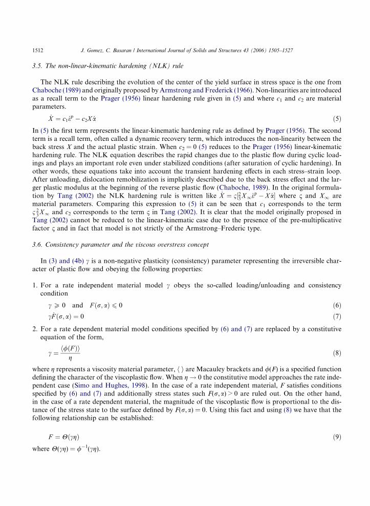
A finite element simulation of the nanoindentation test was performed using the commercial finite ele-ment code ABAQUS and the material constitutive model described in Section 3. The constitutive model iscoupled to ABAQUS via a UMAT material user subroutine. The simulated experiments correspond tothose with a pyramidal Berkovitch indenter on several (same properties) Pb/Sn solder alloy specimens.The 3D pyramidal Berkovich indenter is modeled with an equivalent cone thus allowing treatment ofthe problem in terms of a more economical 2D axisymmetric model. The half angle of the cone with equiv-alent volume to area ratio of a Berkovich indenter is taken here like 65.3� after Begley and Hutchinson(1998). Fig. 6 shows a schematic of the indenter-specimen geometry and the assumed boundary conditionsafter taking advantage of the symmetry. Details of the most relevant geometric properties of the indenta-tion process are depicted in Fig. 7 where a represents the contact radius, h the indentation depth and hc thecontact depth. The contact depth hc is measured with respect to the free surface in the deformed configu-ration reflecting the effects of pile-up or sink-in. The indentation depth is measured with respect to theoriginal (undeformed) free surface. The finite element mesh consists of 15,242 nodes and 15,596 4-nodedaxisymmetric elements. The indenter is assumed like infinitely rigid and described in terms of an analyticrigid surface. The overall mesh and details of the mesh near the indenter tip are shown in Figs. 8 and 9,respectively. The mesh is highly refined near the contact zone so the penetration profile can be describedaccurately. The characteristic element size progressively increases towards the far edges of the model.
4.2. Simulations and results
In the simulations we have applied a maximum penetration of 4.0 lm which corresponds to the maxi-mum value in the performed experiments. However, interest is focused to small penetration depths(<2.0 lm) where the apparent size effects are clearly observed during testing (see Fig. 1). For the numericalanalysis the contact problem is set up like a displacement controlled problem where a reference point in therigid surface (indenter) is gradually displaced towards the specimen according to an amplitude curve scaledto reproduce a desired penetration rate. An initial simulation is performed using the rate independent elas-to-plastic-non-linear combined isotropic/kinematic hardening constitutive model built-in within ABAQUS.With this model the material properties are considered to be temperature independent and measured atroom temperature. This model represents the limiting case of our rate dependent model when g approaches
Fig. 6. Schematic of nanoindentation model showing assumed boundary conditions.
hhc
a
Deformed surface
Original surface
P
Fig. 7. Details of nanoindentation experiment.
Fig. 8. Complete finite element mesh for the solder specimen.
1520 J. Gomez, C. Basaran / International Journal of Solids and Structures 43 (2006) 1505–1527
0.0. Results for this simulation in terms of load vs displacement and hardness vs indentation depth areshown in Figs. 10 and 11, respectively. The predicted values of hardness are constant or size independentover the range of considered depths with a predicted value of 0.60 GPa. The average hardness for Pb/Snsolder alloys measured from nanoindentation experiment at room temperature is of the order of0.20 GPa with much larger values concentrated at very small depths. We must point out that in the datareported in Fig. 1 all the results corresponding to indentations smaller than 500 nm have been eliminated.This limit is imposed by practical limitations in the specimen preparation process. The basic feature of theresults obtained with the rate independent model is the constant hardness over the range of displacementsand the nonconservative predictions of the actual hardness. This is somehow expected since the model isunable to capture the temperature and stress dependent response of the material. The same simulation isrepeated using our own constitutive model for different temperatures and penetration rates. The covered

Fig. 9. Mesh near the indenter zone.
Fig. 10. Load–displacement results for the ABAQUS built in rate independent non-linear combined isotropic/kinematic hardeningconstitutive model.
J. Gomez, C. Basaran / International Journal of Solids and Structures 43 (2006) 1505–1527 1521
temperatures are 0 �C, 22 �C, (room temperature) and 100 �C. The penetration rates are 0.10 lm/s,0.20 lm/s and 0.40 lm/s. The simulation at room temperature and 0.20 lm/s corresponds to the performed

Fig. 11. Hardness–indentation depth results for the ABAQUS built in rate independent non-linear combined isotropic/kinematichardening constitutive model.
1522 J. Gomez, C. Basaran / International Journal of Solids and Structures 43 (2006) 1505–1527
experiments. Numerical and experimental results are compared in Figs. 12 and 13 and good agreementbetween the experiment and the simulation is generally obtained. Moreover, the numerical results are largernear the small penetration depths as exhibited by the experimental results. This result is obtained eventhough our model is not equipped with any intrinsic material length scale and therefore it is unable to pre-dict size effects associated to storage of geometrically necessary dislocations as in the theories from Flecket al. (1994), Fleck and Hutchinson (1997). The simulation at room temperature and penetration rate of
Fig. 12. Load–displacement for the rate dependent model at room temperature and penetration rate of 0.20 lm/s comparisons withexperimental results.

Fig. 13. Load–displacement for a rate dependent model at room temperature and penetration rate of 0.20 lm/s and comparisons withexperimental results.
J. Gomez, C. Basaran / International Journal of Solids and Structures 43 (2006) 1505–1527 1523
0.20 lm/s is compared with those at 0 �C and 100 �C in Fig. 14. The apparent size effect is stronger and theaverage value of the hardness is larger for the low temperature. For the 100 �C simulation the apparent sizeeffect completely vanishes and the prediction is similar to the one from the rate independent model but witha smaller value of hardness. This is again expected since the material is considerable softer. The same threesimulations are repeated for a larger value of the penetration rate. The results are displayed in Fig. 15 and
Fig. 14. Comparisons of hardness–indentation depth using a rate dependent model at different temperatures and penetration rate of0.20 lm/s.

Fig. 15. Comparisons of hardness–indentation depth for a rate dependent model at different temperatures and penetration rate of0.40 lm/s.
1524 J. Gomez, C. Basaran / International Journal of Solids and Structures 43 (2006) 1505–1527
the same trend as in the previous case is observed. The apparent size effect as observed from the data cor-responding to the low temperature regime is stronger for this higher penetration rate. Fig. 16 shows resultsat room temperature and different indentation-defined values of the strain rate ( _h=h). It is clear that theapparent size effect increases in the direction of increasing strain rate. The above set of results exhibitsthe trend suggested by Cheng and Cheng (2000) where dimensional analysis performed on power law creep
Fig. 16. Hardness–indentation depth for a rate dependent model at room temperature and different indentation-defined strain rates.
J. Gomez, C. Basaran / International Journal of Solids and Structures 43 (2006) 1505–1527 1525
solids show that the force during loading is proportional to h2�m and therefore the hardness decreases withincreasing indentation depth.
5. Conclusions
The paper uses a thermodynamics-based damage-mechanics-coupled rate-dependent constitutive modelfor eutectic Pb/Sn solder alloys in order to study the nanoindentation experiment at small indentationdepths. The J2-flow theory equations and a new integration scheme for the constitutive framework are fullydescribed. Material parameters that feed the model and obtained from an experimental study, Tang (2002),are reported together with results from an additional verification study using monotonic and fatigue sheartesting of homemade thin layer solder joints. With the available constitutive model and material parameterswe have performed numerical simulations of the nanoindentation experiment for a range of temperaturesand penetration rates. The present simulation distinguishes itself from similar ones in the sense that we haveused a complete constitutive framework which is capable of capturing the rate and temperature dependencefeatures of the material response. Using this capability our study is strictly directed to the response at smallindentation depths. As opposed to a rate independent model, the results from our thermodynamics basedframework can reproduce the apparent size dependent response observed during the nanoindentationexperiment. We refer to the size dependent response observed here as apparent because in contrast tothe case of other materials the increase in response with decreasing depth is not due to the accumulationof geometrically necessary dislocations. In our simulations the apparent size dependent response is strongerat low temperatures and higher penetration rates and it vanishes for temperatures above room temperature.The results from an equivalent rate independent model clearly over predict the average experimental hard-ness values and the apparent size dependence is not captured. From the above numerical results it can beconcluded that in the case of Pb/Sn eutectic solder alloys which are commonly used in the microelectronicsindustry, a constitutive model that can capture the temperature and rate dependence response is sufficientlyaccurate. Moreover, non-classical theories with additional material parameters in the form of length scalesare unnecessary. As opposed to a rate independent material in the case of the present material, dislocationmobilization is promoted and facilitated due to thermally activated diffusion processes.
References
Adams, P.J., 1986. Thermal fatigue of solder joints in micro-electronic devices. M.S. thesis, Department of Mechanical Engineering,MIT, Cambridge, MA.
Aifantis, E., 2003. Update on a class of gradient theories. Mechanics of Materials 35, 259–265.Armstrong, P.J., Frederick, C.O., 1966. A mathematical representation of the multiaxial Bauschinger effect. CEGB Report RD/B/
N731.Ashby, M., 1970. The deformation of plastically non-homogenous materials. Philosophical Magazine 21, 399–424.Basaran, C., Chandaroy, R., 1998. Mechanics of Pb40/Sn60 near eutectic solder alloys subjected to vibrations. Applied Mathematical
Modeling 22, 601–627.Basaran, C., Tang, H., 2002. Implementation of a thermodynamic framework for damage mechanics of solder interconnect in
microelectronic packaging. In: Proceedings of IMECE, 2002 ASME International Mechanical Engineering Congress & Exposition,New Orleans, Louisiana.
Basaran, C., Yan, C., 1998. A thermodynamic framework for damage mechanics of solder joints. Journal of Electronic Packaging,Transactions of ASME 120, 379–384.
Basaran, C., Chandaroy, R., Zhao, Y., 1998. Influence of grain size and microstructure on dynamic response of solder joints 98-WA/EEP-12. ASME Publications.
Bhattacharya, A., Nix, W., 1988a. Analysis of elastic and plastic deformation associated with indentation testing of thin films onsubstrates. International Journal of Solids and Structures 24 (12), 1287–1298.

1526 J. Gomez, C. Basaran / International Journal of Solids and Structures 43 (2006) 1505–1527
Bhattacharya, A., Nix, W., 1988b. Finite element simulation of indentation experiments. International Journal of Solids and Structures24 (9), 891.
Begley, M., Hutchinson, J.W., 1998. The mechanics of size dependent indentation. Journal of the Mechanics and Physics of Solids 46(10), 2049–2068.
Bucaille, J., Stauss, S., Felder, E., Michler, J., 2003. Determination of plastic properties of metals by instrumented indentation usingdifferent sharp indenters. Acta Materialia 51, 1663–1678.
Busso, E.P., Kitano, M., Kumazawa, 1992. A visco-plastic constitutive model for 60/40 tin–lead solder used in IC package joints.Journal of Engineering Materials and Technology 114, 331–337.
Chaboche, J.L., 1989. Constitutive equations for cyclic plasticity and viscoplasticity. International Journal of Plasticity 3, 247–302.Cheng, Y., Cheng, C., 1998. Scaling approach to conical indentation in elastic–plastic solids with work hardening. Applied Physics
Letters 84 (3), 1284–1291.Cheng, Y., Cheng, C., 2000. What is indentation hardness? Surface and Coatings Technology 133, 417–424.Chudoba, T., Richter, F., 2001. Investigation of creep behaviour under load during indentation experiments and its influence on
hardness and modulus results. Surface and Coatings Technology 148, 191–198.Darveaux, R., Banerji, K., 1992. Constitutive relations for tin-based solder joints. IEEE Transactions on Components Hybrids and
Manufacturing Technology 15 (6), 1013–1024.Feng, G., Ngan, A., 2001. Creep and strain burst in indium and aluminum during nanoindentation. Scripta Materialia 45, 971–976.Fleck, N., Hutchinson, J., 1993. A phenomenological theory for strain gradient effects in plasticity. Journal of the Mechanics and
Physics of Solids 41 (12), 1825–1857.Fleck, N., Hutchinson, J., 1997. Strain gradient plasticity. In: Advances in Applied Mechanics, vol. 33, pp. 295–361.Fleck, N., Muller, G., Ashby, M., Hutchinson, J., 1994. Strain gradient plasticity: theory and experiment. Acta Metallurgica et
Materialia 42 (2), 475–487.Gao, H., Huang, Y., Nix, W., 1999. Modeling plasticity at the micrometer scale. Natur Wissenschaften 86, 507–515.Giannakopoulus, A., Suresh, S., 1996a. Indentation of solids with gradients in elastic properties: Part I. Point force. International
Journal of Solids and Structures 34 (19), 2357–2392.Giannakopoulus, A., Suresh, S., 1996b. Indentation of solids with gradients in elastic properties: Part II. Axisymmetric indentors.
International Journal of Solids and Structures 34 (19), 2393–2428.Herbert, E., Pharr, G., Oliver, W., Lucas, B., Hay, L., 2001. On the measurement of stress–strain curves by spherical indentation. Thin
Solid Films 398–399, 331–335.Hertz, H., 1882. Uber die beruhrung fester elastischer koper. Journal Reine Angewandte Mathematic 92, 156–171.Hertz, H., 1896. Miscellaneous Papers by H. Hertz. Macmillan, London.Hong, B.Z., Burrell, L.G., 1995. Nonlinear finite element simulation of thermoviscoplastic deformation of C4 solder joints in high
density packaging under thermal cycling. IEEE Transactions of Components, Packaging, and Manufacturing Technology—Part A18 (3), 585–590.
Huber, N., Nix, W., Gao, H., 2002. Identification of elastic–plastic material parameters from pyramidal indentation of thin films.Proceedings of the Royal Society of London A 458, 1593–1620.
Huang, Y., Xue, Z., Gao, H., Nix, W., Xia, Z., 2000. A study of micro-indentation hardness tests by mechanism-based strain gradientplasticity. Journal of Materials Research 15, 1786–1796.
Kashyap, B., Murty, G., 1981. Experimental constitutive relations for the high temperature deformation of a Pb–Sn eutectic alloy.Material Science and Engineering 50, 205–213.
Kitano, B.P., Kawai, S., Shimizu, L., 1988. Thermal fatigue strength estimation of solder joints of surface mount IC packages. In:Proc. 8th Annual Int. Elec. Packaging Conf., IEPS, Dallas, Texas, pp. 4–8.
Knocht, S., Fox, L.R., 1990. Constitutive relation and creep-fatigue life model for eutectic tin–lead solder. IEEE Transactions onComponents Hybrids and Manufacturing Technology 13, 424–433.
Krempl, E., 1999. Viscoplastic models for high temperature applications. International Journal of Solids and Structures 37, 279–291.Lau, J., Rice, J.R., 1990. Thermal stress/strain analyses of ceramic quad flat pack packages and interconnects. In: Elect. Components
and Technology 40th Conf., vol. 1, pp. 824–934.Lemaitre, J., 1996. A Course on Damage Mechanics. Springer-Verlag, Germany.Li, X., Bhushan, B., 2002. A review of nanoindentation continuous stiffness measurement technique and its applications. Materials
Characterization 48, 11–36.Lubarda, V., Benson, D., 2002. On the numerical algorithm for isotropic–kinematic hardening with the Armstrong–Frederick
evolution of the back stress. Computer Methods in Applied Mechanics and Engineering 191, 3583–3596.Ma, Q., Clarke, D.R., 1995. Size dependent hardness in silver single crystals. Journal of Materials Research 10, 853–863.Ma, X., Yoshida, F., 2003. Rate dependent indentation hardness of a power-law creep solder alloy. Applied Physics Letters 82 (2),
188–190.Ma, X., Yoshida, F., Shinbata, K., 2003. On the loading curve in microindentation of viscoplastic solder alloy. Materials Science and
Engineering A 344, 296–299.

J. Gomez, C. Basaran / International Journal of Solids and Structures 43 (2006) 1505–1527 1527
McDowell, D.L., Miller, M.P., Brooks, D.C., 1994. A unified creep-plasticity theory for solder alloys. Fatigue Testing of ElectronicMaterials ASTM STP 1153, 42–59.
Nix, W., Gao, H., 1998. Indentation size effects in crystalline materials: a law for strain gradient plasticity. Journal of the Mechanicsand Physics of Solids 46 (3), 411–422.
Nye, J., 1953. Some geometrical relations in dislocated crystals. Acta Metallurgica 1, 153–162.Oliver, W., Pharr, G., 1992. An improved technique for determining hardness and elastic modulus using load and displacement sensing
indentation experiments. Journal of Materials Research 7 (6), 1564–1583.Owen, D.R.J., Hinton, E., 1980. Finite Element in Plasticity. Pineridge Press Limited, Swansea, UK.Poole, W., Ashby, M., Fleck, N., 1996. Micro-hardness of annealed and work-hardened of copper polycrystals. Scripta Mettallurgica
et Materialia 34 (4), 559–564.Prager, W., 1956. A new method of analyzing stress and strains in work-hardening plastic solids. Journal of Applied Mechanics 23,
493–496.Shu, J.Y., Fleck, N.A., 1997. The prediction of size effect in micro-indentation. Journal of Solids and Structures 35 (13), 1363–1383.Simo, J., Hughes, T., 1998. Computational Inelasticity. Interdisciplinary Applied Mathematics. Springer.Skipor, A.F., Harren, S.V., Botsis, J., 1996. On the constitutive response of 63/37 Sn/Pb eutectic solder. Journal of Engineering
Materials and Technology 118, 1–11.Stelemashenko, N.A., Walls, M.G., Brown, L.M., Milman, Y.V., 1993. Microindentation on W and Mo oriented single crystals: an
STM study. Acta Metallurgica et Materialia 41, 2855–2865.Tachibana, Y., Krempl, E., 1995. Modeling the high homologous temperature deformation behavior using the viscoplasticity theory
based on overstress (VBO): Part I. Creep and tensile behavior. Journal of Engineering Materials and Technology 117, 456–461.Taljat, B., Pharr, G., 2004. Development of pile-up during spherical indentation of elastic–plastic solids. International Journal of
Solids and Structures 41 (14), 3891–3904.Tang, H., 2002. A thermodynamic damage mechanics theory and experimental verification for thermomechanical fatigue life
prediction of microelectronics solder joints. Ph.D. dissertation, University at Buffalo, The State University of New York.Timoshenko, S., Goodier, N., 1951. Theory of Elasticity. McGraw-Hill, New York.Wei, Y., Chow, C.L., Fang, H.E., Neilsen, M.K., 1999. Characteristics of creep damage for 60Sn–40Pb solder material. ASME 99-
IMECE/EEP-15.Wilcox, J.R., Subrahmanyan, R., Li, C., 1989. Thermal stress cycles and inelastic deformation in solder joints. In: Proc. 2nd ASME
Int. Electronic Mat. and Processing Congr., Philadelphia, PA, pp. 208–211.Xue, Z., Huang, Y., Hwang, K.C., Li, M., 2002a. The influence of indenter tip radius on the micro-indentation hardness. Journal of
Engineering Materials and Technology 124, 371–379.Xue, Z., Huang, Y., Li, M., 2002b. Particle size effect in metallic materials: a study by the theory of mechanism-based strain gradient
plasticity. Acta Materialia 50, 149–160.


![Development of a framework for risk tradeoff analysis of ... · lead solder alloys by ‘lead-free solder alloys,’ such as tin-silver-copper alloys, which do not contain lead; [3]](https://img.pdfslide.us/doc/110x75/5f7e3207b7b7e8677f1fc606/development-of-a-framework-for-risk-tradeoff-analysis-of-lead-solder-alloys.jpg)


![Pb-Free Alloys Paper[1]](https://img.pdfslide.us/doc/110x75/577cd7881a28ab9e789f35c9/pb-free-alloys-paper1.jpg)