Embed Size (px)
Citation preview

PAPER www.rsc.org/loc | Lab on a Chip
Nanoarrays of tethered lipid bilayer rafts on poly(vinyl alcohol) hydrogels†
Bong Kuk Lee,a Hea Yeon Lee,*a Pilnam Kim,b Kahp Y. Suhb and Tomoji Kawai*a
Received 9th June 2008, Accepted 2nd September 2008
First published as an Advance Article on the web 22nd October 2008
DOI: 10.1039/b809732a
Lipid rafts are cholesterol- and sphingolipid-rich domains that function as platforms for signal
transduction and other cellular processes. Tethered lipid bilayers have been proposed as a promising
model to describe the structure and function of cell membranes. We report a nano(submicro) array of
tethered lipid bilayer raft membranes (tLBRMs) comprising a biosensing platform. Poly(vinyl alcohol)
(PVA) hydrogel was directly patterned onto a solid substrate, using ultraviolet-nanoimprint
lithography (UV-NIL), as an inert barrier to prevent biofouling. The robust structures of the
nanopatterned PVA hydrogel were stable for up to three weeks in phosphate-buffered saline solution
despite significant swelling (100% in height) by hydration. The PVA hydrogel strongly restricted the
adhesion of vesicles, resulting in an array of highly selective hydrogel nanowells. tLBRMs were not
formed by direct vesicle fusion, although raft vesicles containing poly(ethylene glycol) lipopolymer
were selectively immobilized on gold substrates patterned with PVA hydrogel. The deposition of
tLBRM nano(submicro) arrays was accomplished by a mixed, self-assembled monolayer-assisted
vesicle fusion method. The monolayer was composed of a mixture of 2-mercaptoethanol and
poly(ethylene glycol) lipopolymer, which promoted vesicle rupture. These results suggest that the
fabrication of inert nanostructures and the site-selective modification of solid surfaces to induce
vesicle rupture may be essential in the construction of tLBRM nano(submicro) arrays using stepwise
self-assembly.
Introduction
The lipid ‘‘raft’’ hypothesis proposes that different lipids found in
plasma membranes have different biophysical propensities to
associate with each other.1,2 Lipid rafts are defined as phase-
segregated domains enriched in cholesterol, sphingolipids, and
certain proteins.1,2 It has been suggested that lipid rafts play
a role in a wide range of biological processes, such as signal
transduction pathways, apoptosis, cell adhesion and migration,
and protein sorting.3 In addition to normal cellular functions, it
has also been suggested that lipid rafts serve as functional hot-
spots for bacteria, viruses and toxins, as well as providing
a microenvironment for prion formation and amyloid aggrega-
tion.4 Phase-separated domains in lipid bilayers can range in size
from nanoscale5 to microscale,6 depending on the lipid mixture.
Lipid membranes with well-defined domains may be useful
for the study of lipid raft dynamics, transmembrane proteins,
membrane-associated proteins, and for the realization of bio-
logical interconnections and building blocks in nanodevices or
nanochips. However, a model lipid membrane system that has
aThe Institute of Scientific and Industrial Research (ISIR), OsakaUniversity, 8-1 Mihogaoka, Ibaraki, Osaka, 567-0047, Japan. E-mail:[email protected]; [email protected]; Fax: +81-6-6875-2440; Tel: +81-6-6879-8447bSchool of Mechanical and Aerospace Engineering, Seoul NationalUniversity, Seoul, 151-742, Korea
† Electronic supplementary information (ESI) available: Included arefigures showing the initial film thickness of PVA as a function ofspin-coating velocity (Fig. S1), the UV irradiation dose for curing PVA(Fig. S2), the DSC heat flow curve (Fig. S3), the AFM images ofnanoimprinted PVA at stage III (Fig. S4) and the AFM images of lipidbilayer on mica (Fig. S5). See DOI: 10.1039/b809732a
132 | Lab Chip, 2009, 9, 132–139
well-controlled domain sizes, as well as the appropriate structure
necessary for lipid raft-based research has not been developed.
Lipid bilayer membranes (LBMs), such as solid-supported
lipid bilayer membranes (sLBMs),7 hybrid bilayer membranes,8
polymer-cushioned lipid bilayer membranes (cLBMs),9 and
tethered lipid bilayer membranes (tLBMs),10 deposited on
a variety of substrates, have been developed as experimental
model membranes. In addition, there is a great deal of interest in
the development of LBM microarrays to localize and parallelize
studies on membrane functions. Due to their importance in the
design of biocompatible surfaces and membrane-based research,
model LBMs have been developed for nearly all fields of cellular
research including studies of membrane properties,6 biosensing
platforms,9 cell adhesion,11 characterization of membrane-asso-
ciated proteins,12 and drug discovery.13,14 Among various model
membranes, microarrays of sLBMs have been widely investi-
gated. To facilitate the formation of sLBM arrays, materials,
such as metals and metal oxides,15 diacetylene lipids,16 poly-
ethylene glycol (PEG)-copolymer,17 and proteins,18 have been
used as patterned barriers on solid supports. Patterning methods
include photolithography,15 deep-UV illumination,16 capillary
molding,17 microcontact printing,18 and polymer lift-off.11
However, it has been reported that the membrane-substrate
distance (5–20 A)19 of sLBMs is usually not sufficiently large to
avoid direct contact between transmembrane proteins incorpo-
rated in the membrane and the solid surface. Previous studies
have suggested that delamination between the membrane and the
solid substrate using soft polymeric materials, such as a polymer
‘‘cushion’’9,20 or polymer ‘‘tethers,’’20–22 could reduce the risk of
protein denaturation by contact with the solid substrates. Both
cLBMs and tLBMs are considered promising architectural
This journal is ª The Royal Society of Chemistry 2009

Scheme 1 (a) Schematic diagram showing the fabrication of PVA
nanostructures with thermal-assisted UV-NIL. (b) Schematic diagram of
the proposed morphology of a lipid raft as a form of tethered lipid bilayer
membrane (tLBRM) in the nanopatterned PVA hydrogel on a gold
substrate (Au). The raft membrane, comprised of a mixture of POPC/
SM/cholesterol (1 : 1 : 1 molar ratio), was formed on a mixed SAM of
2-mercaptoethanol (ME) and PEG lipopolymer (DSPE-PEG-PDP) in
the PVA nanowell.
models that mimic the structure and function of natural bio-
membranes, including the formation of lipid rafts. However,
there have been relatively few studies on cLBM23–25 and tLBM26
arrays. Moreover, the arrays of cLBMs and tLBMs have
remained on the microscale, and there have been no other studies
on nanoarrays of raft-forming LBMs in the literature.
The aim of this study was to create a nanoarray of tLBRMs on
patterned substrates, to generate a membrane-based biosensing
platform. For this purpose, the patterns must be scaled down from
microscale to nanoscale. Nanoimprint lithography (NIL) is
a simple, low-cost, and high-resolution nanopatterning method.27,28
We have previously reported the nanoarray of protein29 and single
liposome30 with a nanopatterned PEG at the 100 nm scale was
fabricated by ultraviolet (UV)-NIL and soft lithography, respec-
tively. These results suggest that the direct fabrication of the
nanopatterns with an inert material to protect against biofouling
significantly simplified both the patterning process and the self-
assembled nano(submicro) array of biomolecules.
Here, we report a very effective and widely applicable method
for constructing a nanoarray of tLBRMs by using NIL. UV-
curable poly(vinyl alcohol) (PVA) was used as an inert material
because it minimizes protein adsorption and cell adhesion.31,32
The nanopatterns of PVA hydrogel, that is cross-linked into the
swollen polymer network but does not dissolve in water, was
fabricated by thermal-assisted UV-NIL (Scheme 1a). Morpho-
logical changes and stability of the PVA hydrogel nanostructures
in aqueous solution were determined by atomic force microscopy
(AFM). This technique was also used to demonstrate the fabri-
cation of tLBRM nanoarrays with nanoimprinted PVA hydrogel
(Scheme 1b). A direct vesicle fusion method,7,33 and a mixed,
self-assembled monolayer (SAM)-assisted vesicle fusion
method,21,34,35 were carried out to construct a tLBRM nanoarray
within the nanostructured barriers of the PVA hydrogel.
Materials and methods
Materials
UV-curable PVA (AWP: solid content 6 wt%) was provided by
Toyo Gosei Kogyo Co. (Chiba, Japan). Optool DSX (20%
perfluorinated compounds) and Demnum solvent (80%
perfluoroisohexane) were obtained from Daikin Industries
(Osaka, Japan). Sphingomyelin (SM), cholesterol, 1-palmitoyl-
2-oleoyl-sn-glycero-3-phosphocholine (POPC), and 1,2-dis-
tearoyl-sn-glycero-3-phosphoethanolamine-N-poly(ethylene
glycol)-2000-N-[3-(2-(pyridyldithio)propionate]) (DSPE-PEG-
PDP) were purchased from Avanti Polar Lipids Inc. (Alabaster,
AL, USA). Texas-Red 1,2-dihexadacanoyl-sn-glucero-phos-
phoethanolamine (TR-DHPE) was purchased from Molecular
Probes (Eugene, OR, USA). 2-Mercaptoethanol was purchased
from Sigma-Aldrich (St. Louis, MO USA) and used without
further purification.
Thermal-assisted ultraviolet-nanoimprint lithography (UV-NIL)
Gold (Au) substrates were prepared by sputtering high-purity
gold (99.999%) onto cleaned SiO2 wafers with a titanium (Ti)
adhesion layer (100 nm Au and 5 nm Ti). The substrates were
cleaned with UV-ozone for 30 min with an ozone cleaner (NL-
UV253; Nippon Laser Denshi, Tokyo, Japan). To fabricate the
This journal is ª The Royal Society of Chemistry 2009
nanostructure of PVA hydrogel, thermal-assisted UV-NIL was
carried out using an instrument from Nanoimprinter Systems
(NM-401; Meisyo Kiko, Hyogo, Japan) equipped with a UV
lamp (Toscure251; Toshiba, Tokyo, Japan) (Scheme 1a). The
substrates were then spin-coated with a thin film of UV-curable
PVA, followed by prebaking at 50 �C for 5 min. The PVA-coated
substrates were heated to above the glass transition temperature
(Tg: 40.5 �C) of PVA. A positive quartz mold (100 nm in height),
coated with 0.1 wt% Optool DSX as a release agent to prevent
adhesion of cured resist to the mold, was then pressed for 5 min
at an imprint pressure of 2 MPa at 80 �C under vacuum. After
cooling to room temperature while maintaining the pressure, the
PVA was cured using UV irradiation (wavelength, 365 nm; dose,
100 mJ cm�2 UV). The mold was then removed from the
substrate. Residual PVA was subsequently removed by argon
reactive ion etching (RIE: Ar gas flow ¼ 10 sccm, pressure ¼ 4
Pa, power ¼ 50 W) using an RIE system (RIE-10NR; Samco
Inc., Tokyo, Japan). The etching time was varied to control
the depth of the nanowells.
Swelling measurements of PVA hydrogel
Dry hydrogel samples, prepared by UV irradiation, were
immersed in an excess of Milli-Q deionized water or 10 mM
Lab Chip, 2009, 9, 132–139 | 133

phosphate-buffered saline (PBS) at room temperature. At
specific time intervals, the samples were removed from the water
or 10 mM PBS and excess surface water was dried with filter
paper. The swollen mass (Ws) was weighed until the hydrated
gels reached a constant weight. The hydrogel samples were
subsequently dried for 48 h in desiccators at room temperature
and their dry weights (Wd) were recorded.
Lipid vesicle preparation
Model raft vesicles5,36 were prepared by the extrusion method.
Briefly, a lipid mixture of POPC, SM, and cholesterol (1 : 1 :
1 molar ratio), with or without 5 mol% DSPE-PEG-PDP, was
dissolved in chloroform and mixed in a round-bottomed flask.
The organic solvent was evaporated using a rotary evaporator
(RE 440; Yamato Scientific Co., Ltd., Tokyo, Japan) at 45 �C in
a water bath and vacuum-desiccated overnight. The dry lipid film
was hydrated in 10 mM PBS at 45 �C and vortexed for 30 min to
generate multilamellar vesicles. The resulting vesicles were freeze-
thawed five times to prepare the unilamellar vesicles. Subse-
quently, uniformly sized vesicles were obtained by extrusion of
the unilamellar vesicles through polycarbonate filters with a pore
diameter of 100 nm in an extrusion apparatus (Avestin Inc.,
Ottawa, ON, Canada). Vesicle size and PEG lipopolymer
dimensions were confirmed by non-invasive back-scattering
method in 10 mM PBS (Zetasizer Nano ZS; Malvern Instru-
ments Ltd., Malvern, Worcestershire, UK).
Construction of tBLRM nanoarray
Two methods were used to confine the tBLRM to the nano-
patterned PVA hydrogel: a vesicle fusion method and a mixed
self-assembled monolayer (SAM)-assisted vesicle fusion method.
For a vesicle fusion method, a few drops of raft vesicles con-
taining 5 mol% DSPE-PEG-PDP were evenly distributed onto
the patterned PVA hydrogel and incubated at room temperature
for 1 h, and then the sample was rinsed thoroughly with PBS. For
a mixed SAM-assisted vesicle fusion method, the mixtures of
1 mM DSPE-PEG-PDP and 9 mM ME were dissolved in 10 mM
PBS buffer. One-step mixed SAM was prepared by immersing
the PVA patterned gold substrates in the mixtures of DSPE-
PEG-PDP/ME at room temperature for 2 h and the sample was
rinsed with PBS several times to remove excess molecules.
Subsequently, a model raft vesicles comprising a mixture of
POPC/SM/cholesterol (1 : 1 : 1 molar ratio) was dropped on PVA
patterned gold substrate modified with a mixed SAM. After 2 h
at room temperature, the excess unfused vesicles were flushed out
of the PVA patterned gold substrates. To confirm the formation
of single lipid bilayer on the mixed SAM, the micropattern of the
DSPE-PEG-PDP/ME mixed SAM was fabricated on gold
substrate by combining polymer lift-off and molecular assembly.
For the polymer lift-off, a thin film of 125 nm of the poly(methyl
methacrylate) (PMMA; MicroChem Corp., Newton, MA, USA)
was imprinted at the temperature of 150 �C and pressure of
5 MPa for 5 min after prebaked at 80 �C for 5 min. After expose
the gold surface by Ar RIE, the substrates patterned with
PMMA was modified with the mixed SAM for 2 h, followed by
the PMMA lift-off by the sonication in acetone at 45 �C for 1 h.
The sample was then rinsed with excess Milli-Q several times.
134 | Lab Chip, 2009, 9, 132–139
The formation of lipid bilayer on the patterned mixed SAM was
carried out by the addition of a few drops of 1 mM raft vesicles.
Fluorescence microscopy
Fluorescence microscopy was performed using an Olympus
BX51 inverted research microscope equipped with a fluorescence
attachment (IX-FLA; Olympus, Tokyo, Japan) and a high-
resolution digital camera (DP70; Olympus) for image acquisi-
tion. Red emission light (>590 nm) was filtered using a U-MWG
Olympus filter cube.
Atomic force microscopy (AFM)
To image the patterned hydrogel and lipid bilayers, we used
a Digital Instruments NanoScope III atomic force microscope
(Veeco Instruments Inc., Woodbury, NY, USA) in tapping mode
in both air and aqueous phases at ambient temperature. The scan
rate was 0.5 Hz and 512 lines were scanned per sample. AFM
imaging in air was carried out with a silicon cantilever with
a nominal spring constant of 2 N m�1 (Olympus). AFM imaging
in aqueous solutions was carried out with the aid of a fluid cell
and a V-shaped silicon nitride cantilever with a nominal spring
constant of 0.58 N m�1 (Veeco Metrology Group, Tucson, AZ,
USA). The imaging force was minimized to limit deformation of
the hydrogel by the AFM cantilever. Data were processed using
SPIP V3.3.7.0 software (Image Metrology, Lyngby, Denmark).
Results and discussion
Nanopatterning of PVA hydrogel using UV-NIL
The effects of initial film thickness, glass transition temperature
(Tg), and UV irradiation dose were investigated to optimize the
NIL process using PVA. Based on the results of these investi-
gations, a film of PVA 137 nm thick was spin-coated onto gold or
SiO2 substrates (Figure S1, ESI).† The UV irradiation dose for
curing the PVA and the imprinting temperature were 100 mJ
cm�2 and 80 �C above Tg (40.5 �C) of PVA, respectively
(Figure S2 and S3, ESI).† The nano(submicron) patterns of PVA
hydrogel was fabricated by thermal-assisted UV-NIL process as
shown in Scheme 1a.
Fig. 1 shows the height and cross-sectional atomic force
microscopy (AFM) images of the 500 nm patterns of the dry
PVA hydrogel on a gold substrate before and after argon (Ar)
reactive ion etching (RIE). When the mold was removed from the
substrates (Fig. 1a and 1c), the depth of the imprinted PVA
patterns was the same height (100 nm) as the mold under
thermal-assisted UV-NIL conditions (Fig. 1a and 1c). The micro/
nanopatterns of the PVA hydrogel with the feature size down to
100 nm were successfully fabricated through thermal-assisted
UV-NIL (Figure S4, ESI).† These indicated that the mold
patterns were faithfully transferred by the imprinting technique.
To expose the gold substrate and control the height of the
patterned PVA hydrogel features, the Ar RIE was subsequently
performed. Height and cross-sectional AFM images shown in
Fig. 1b and 1d indicate that the substrate surface was completely
exposed with good edge definition when removed by Ar RIE (gas
flow ¼ 10 sccm, pressure ¼ 4 Pa, power ¼ 50 W). The etching rate
of dry PVA was about 34 nm min�1.
This journal is ª The Royal Society of Chemistry 2009

Fig. 2 (a) Swelling behavior of PVA hydrogel in 10 mM PBS and
deionized water at room temperature. Dry patterns with a mean height of
58 nm were used. (b, c) Height AFM images of the 500 nm patterned PVA
hydrogels on gold substrate (b) before and (c) after swelling by 10 mM
PBS solution. (d) Cross-sectional AFM images at each sate: (gray line)
dry state and (blue and red lines) hydrated state.
Fig. 1 (a, b) Height and (c, d) cross-sectional AFM images of the 500 nm
patterned PVA hydrogel on gold substrate (a, c) before and (b, d) after Ar
RIE (gas flow ¼ 10 sccm, pressure ¼ 4 Pa, power ¼ 50 W).
Swelling behavior of PVA hydrogel
The swelling behavior of a hydrogel is important, especially in
characterizing morphological changes. The swelling ratio (Qr) of
3 wt% PVA was calculated according to following equation:
Qr ¼ (Ws�Wd)/Wd (1)
Here, Ws and Wd are the weights of the swollen and dry sample,
respectively.
The Qr values of 3 wt% PVA hydrogel in phosphate-buffered
saline solution (10 mM PBS, pH 7.4), and Milli-Q deionized
water, were equilibrated for 2 and 3 arbitrary units for 30 min at
room temperature, respectively (Fig. 2a). Based on these obser-
vations, only PBS was used and the samples were not exposed to
air until AFM measurements were completed. To investigate the
morphological changes of the nanopatterned PVA hydrogel
induced by hydration, the gold substrates patterned with PVA
hydrogel, with a mean feature height of 58 nm, were incubated in
10 mM PBS for 1 h. As shown in Fig. 2c and 3d, the mean height
of the hydrated PVA pattern increased by about twofold
compared to that of the dry PVA (Fig. 2b). Interestingly, a lateral
swelling was not observed within the resolution constraints of the
AFM measurements. This result indicates that the swelling of
PVA hydrogel is highly anisotropic with little change in the
lateral dimensions presumably as a result of the constraints
imposed by the binding of the hydrogel to the substrate surface.
Similar swelling phenomenon for the nanopatterns of PEG
hydrogel have been observed in our previous study.29 The
nano(submicro) patterned PVA hydrogel maintained these
robust structures on the gold surface for at least 3 weeks in PBS,
even though the features were swollen by hydration, and
remained intact in ethanol and acetone for 2 months.
Site-selective confinement of raft vesicles
The feasibility of creating a selective array of vesicles on
patterned PVA hydrogel was confirmed by fluorescence
microscopy. The micro/nanopatterns of the PVA hydrogel were
This journal is ª The Royal Society of Chemistry 2009
fabricated on SiO2 instead of gold substrates due to the
quenching effects of the gold substrate.
Fig. 3a and 3b show optical images of the 1 mm (a) and 500 nm
(b) patterned PVA hydrogel on SiO2 substrates after Ar RIE
(same conditions as in Fig. 1). A suspension of raft vesicles,
containing 1 mol% Texas-red 1,2-dihexadacanoyl-sn-glucero-
phosphoethanolamine (TR-DHPE), was dropped onto the
patterned substrates and incubated at room temperature for 1 h,
and the sample was subsequently rinsed thoroughly with 10 mM
PBS. As shown in the TR-DHPE fluorescence images (Fig. 3c
and 4d), the nonspecific adsorption of vesicles to the PVA surface
was strongly restricted and the vesicles were selectively arrayed
onto the patterned PVA hydrogel. These results indicate that
PVA hydrogels are good, inert materials for the selective
confinement of lipid vesicles and/or bilayers on solid substrates.
In addition, this anti-biofouling effect of PVA may provide the
site-selectivity necessary to achieve the self-assembly of biomol-
ecules on PVA patterned substrates.
Construction of tLBRM nanoarray
Vesicle fusion method. We want to construct a nanoarray of
tLBRMs on gold substrates patterned with PVA hydrogel as
illustrated in Scheme 1b, because the gold substrate is used for
a lot of measurement system such as surface plasmon resonance,
impedance spectroscopy, and surface acoustic wave techniques.
The vesicle fusion method is one of the easiest and most versatile
means of forming substrate-supported LBMs. To construct
a nano(submicro) array of tLBRMs on gold substrates patterned
with PVA hydrogel, the direct vesicle fusion method7,33 was
performed using raft vesicles containing 5 mol% DSPE-PEG-
Lab Chip, 2009, 9, 132–139 | 135
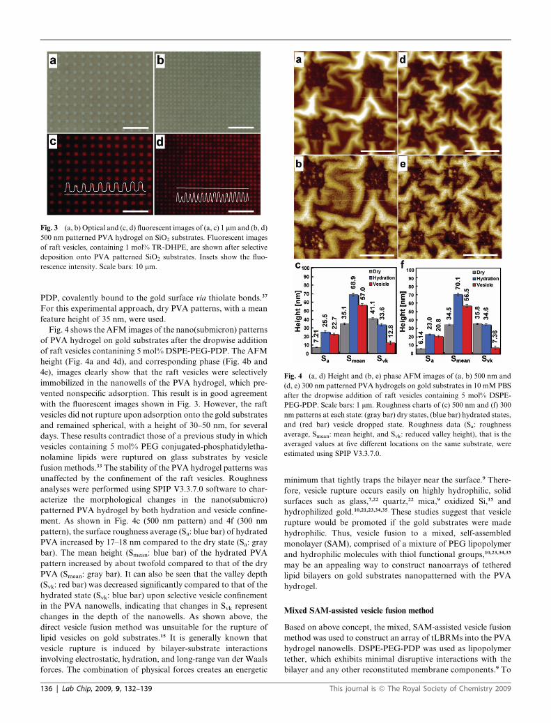
Fig. 3 (a, b) Optical and (c, d) fluorescent images of (a, c) 1 mm and (b, d)
500 nm patterned PVA hydrogel on SiO2 substrates. Fluorescent images
of raft vesicles, containing 1 mol% TR-DHPE, are shown after selective
deposition onto PVA patterned SiO2 substrates. Insets show the fluo-
rescence intensity. Scale bars: 10 mm.
Fig. 4 (a, d) Height and (b, e) phase AFM images of (a, b) 500 nm and
(d, e) 300 nm patterned PVA hydrogels on gold substrates in 10 mM PBS
after the dropwise addition of raft vesicles containing 5 mol% DSPE-
PEG-PDP. Scale bars: 1 mm. Roughness charts of (c) 500 nm and (f) 300
nm patterns at each state: (gray bar) dry states, (blue bar) hydrated states,
and (red bar) vesicle dropped state. Roughness data (Sa: roughness
average, Smean: mean height, and Svk: reduced valley height), that is the
averaged values at five different locations on the same substrate, were
estimated using SPIP V3.3.7.0.
PDP, covalently bound to the gold surface via thiolate bonds.37
For this experimental approach, dry PVA patterns, with a mean
feature height of 35 nm, were used.
Fig. 4 shows the AFM images of the nano(submicron) patterns
of PVA hydrogel on gold substrates after the dropwise addition
of raft vesicles contanining 5 mol% DSPE-PEG-PDP. The AFM
height (Fig. 4a and 4d), and corresponding phase (Fig. 4b and
4e), images clearly show that the raft vesicles were selectively
immobilized in the nanowells of the PVA hydrogel, which pre-
vented nonspecific adsorption. This result is in good agreement
with the fluorescent images shown in Fig. 3. However, the raft
vesicles did not rupture upon adsorption onto the gold substrates
and remained spherical, with a height of 30–50 nm, for several
days. These results contradict those of a previous study in which
vesicles containing 5 mol% PEG conjugated-phosphatidyletha-
nolamine lipids were ruptured on glass substrates by vesicle
fusion methods.33 The stability of the PVA hydrogel patterns was
unaffected by the confinement of the raft vesicles. Roughness
analyses were performed using SPIP V3.3.7.0 software to char-
acterize the morphological changes in the nano(submicro)
patterned PVA hydrogel by both hydration and vesicle confine-
ment. As shown in Fig. 4c (500 nm pattern) and 4f (300 nm
pattern), the surface roughness average (Sa: blue bar) of hydrated
PVA increased by 17–18 nm compared to the dry state (Sa: gray
bar). The mean height (Smean: blue bar) of the hydrated PVA
pattern increased by about twofold compared to that of the dry
PVA (Smean: gray bar). It can also be seen that the valley depth
(Svk: red bar) was decreased significantly compared to that of the
hydrated state (Svk: blue bar) upon selective vesicle confinement
in the PVA nanowells, indicating that changes in Svk represent
changes in the depth of the nanowells. As shown above, the
direct vesicle fusion method was unsuitable for the rupture of
lipid vesicles on gold substrates.15 It is generally known that
vesicle rupture is induced by bilayer-substrate interactions
involving electrostatic, hydration, and long-range van der Waals
forces. The combination of physical forces creates an energetic
136 | Lab Chip, 2009, 9, 132–139
minimum that tightly traps the bilayer near the surface.9 There-
fore, vesicle rupture occurs easily on highly hydrophilic, solid
surfaces such as glass,7,22 quartz,22 mica,9 oxidized Si,15 and
hydrophilized gold.10,21,23,34,35 These studies suggest that vesicle
rupture would be promoted if the gold substrates were made
hydrophilic. Thus, vesicle fusion to a mixed, self-assembled
monolayer (SAM), comprised of a mixture of PEG lipopolymer
and hydrophilic molecules with thiol functional groups,10,23,34,35
may be an appealing way to construct nanoarrays of tethered
lipid bilayers on gold substrates nanopatterned with the PVA
hydrogel.
Mixed SAM-assisted vesicle fusion method
Based on above concept, the mixed, SAM-assisted vesicle fusion
method was used to construct an array of tLBRMs into the PVA
hydrogel nanowells. DSPE-PEG-PDP was used as lipopolymer
tether, which exhibits minimal disruptive interactions with the
bilayer and any other reconstituted membrane components.9 To
This journal is ª The Royal Society of Chemistry 2009
reduce the influence of acyl chains on the lateral fluidity of
bilayers and the formation of lipid rafts, DSPE-PEG-PDP was
diluted 20-fold with 2-mercaptoethanol (ME) in PBS, and was
used to form the mixed SAM. The gold substrates, after being
nanopatterned with PVA hydrogel, were modified with a mixed
SAM. The stepwise self-assembly of both the mixed SAM and
the tLBRMs into the PVA nanowells was characterized by AFM
to record changes in morphology and film thickness. For this
experimental approach, dry PVA patterns, with a mean feature
height of 45 nm, were used.
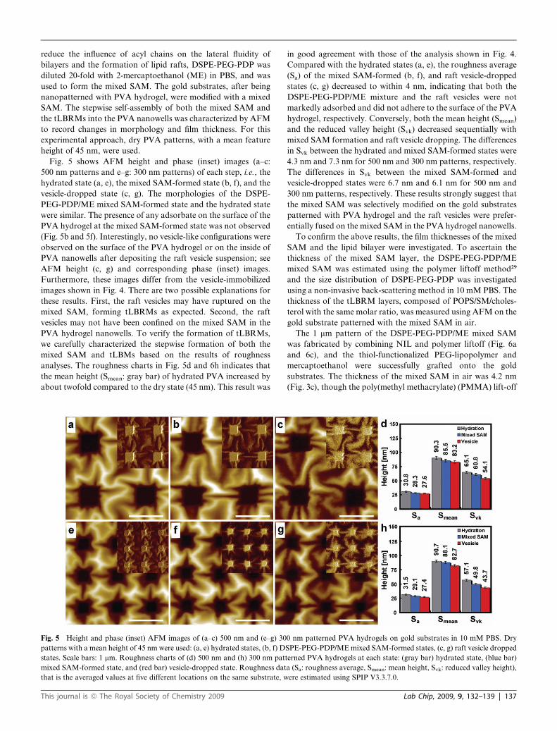
Fig. 5 shows AFM height and phase (inset) images (a–c:
500 nm patterns and e–g: 300 nm patterns) of each step, i.e., the
hydrated state (a, e), the mixed SAM-formed state (b, f), and the
vesicle-dropped state (c, g). The morphologies of the DSPE-
PEG-PDP/ME mixed SAM-formed state and the hydrated state
were similar. The presence of any adsorbate on the surface of the
PVA hydrogel at the mixed SAM-formed state was not observed
(Fig. 5b and 5f). Interestingly, no vesicle-like configurations were
observed on the surface of the PVA hydrogel or on the inside of
PVA nanowells after depositing the raft vesicle suspension; see
AFM height (c, g) and corresponding phase (inset) images.
Furthermore, these images differ from the vesicle-immobilized
images shown in Fig. 4. There are two possible explanations for
these results. First, the raft vesicles may have ruptured on the
mixed SAM, forming tLBRMs as expected. Second, the raft
vesicles may not have been confined on the mixed SAM in the
PVA hydrogel nanowells. To verify the formation of tLBRMs,
we carefully characterized the stepwise formation of both the
mixed SAM and tLBMs based on the results of roughness
analyses. The roughness charts in Fig. 5d and 6h indicates that
the mean height (Smean: gray bar) of hydrated PVA increased by
about twofold compared to the dry state (45 nm). This result was
Fig. 5 Height and phase (inset) AFM images of (a–c) 500 nm and (e–g) 30
patterns with a mean height of 45 nm were used: (a, e) hydrated states, (b, f) D
states. Scale bars: 1 mm. Roughness charts of (d) 500 nm and (h) 300 nm pat
mixed SAM-formed state, and (red bar) vesicle-dropped state. Roughness dat
that is the averaged values at five different locations on the same substrate, w
This journal is ª The Royal Society of Chemistry 2009
in good agreement with those of the analysis shown in Fig. 4.
Compared with the hydrated states (a, e), the roughness average
(Sa) of the mixed SAM-formed (b, f), and raft vesicle-dropped
states (c, g) decreased to within 4 nm, indicating that both the
DSPE-PEG-PDP/ME mixture and the raft vesicles were not
markedly adsorbed and did not adhere to the surface of the PVA
hydrogel, respectively. Conversely, both the mean height (Smean)
and the reduced valley height (Svk) decreased sequentially with
mixed SAM formation and raft vesicle dropping. The differences
in Svk between the hydrated and mixed SAM-formed states were
4.3 nm and 7.3 nm for 500 nm and 300 nm patterns, respectively.
The differences in Svk between the mixed SAM-formed and
vesicle-dropped states were 6.7 nm and 6.1 nm for 500 nm and
300 nm patterns, respectively. These results strongly suggest that
the mixed SAM was selectively modified on the gold substrates
patterned with PVA hydrogel and the raft vesicles were prefer-
entially fused on the mixed SAM in the PVA hydrogel nanowells.
To confirm the above results, the film thicknesses of the mixed
SAM and the lipid bilayer were investigated. To ascertain the
thickness of the mixed SAM layer, the DSPE-PEG-PDP/ME
mixed SAM was estimated using the polymer liftoff method29
and the size distribution of DSPE-PEG-PDP was investigated
using a non-invasive back-scattering method in 10 mM PBS. The
thickness of the tLBRM layers, composed of POPS/SM/choles-
terol with the same molar ratio, was measured using AFM on the
gold substrate patterned with the mixed SAM in air.
The 1 mm pattern of the DSPE-PEG-PDP/ME mixed SAM
was fabricated by combining NIL and polymer liftoff (Fig. 6a
and 6c), and the thiol-functionalized PEG-lipopolymer and
mercaptoethanol were successfully grafted onto the gold
substrates. The thickness of the mixed SAM in air was 4.2 nm
(Fig. 3c), though the poly(methyl methacrylate) (PMMA) lift-off
0 nm patterned PVA hydrogels on gold substrates in 10 mM PBS. Dry
SPE-PEG-PDP/ME mixed SAM-formed states, (c, g) raft vesicle dropped
terned PVA hydrogels at each state: (gray bar) hydrated state, (blue bar)
a (Sa: roughness average, Smean: mean height, Svk: reduced valley height),
ere estimated using SPIP V3.3.7.0.
Lab Chip, 2009, 9, 132–139 | 137

Fig. 6 (a, b) Height and (c, d) cross-sectional AFM images of a 1 mm
patterns of (a, c) the mixed SAM-formed state after PMMA lift-off and
(b, d) the raft vesicle dropped state on gold substrates in air. Inset shows
the size distribution of DSPE-PEG-PDP measured by non-invasive back-
scattering in 10 mM PBS at room temperature.
is not complete. The size of DSPE-PEG-PDP in PBS solution
was 4.2 nm (Inset in Fig. 6a), consistent with above result. This
value was very close to the differences in Svk values between the
hydrated and mixed SAM-formed states. The differences in Svk
values for 500 nm and 300 nm patterns were 4.3 nm and 7.3 nm,
respectively (Fig. 5). Although the differences were more
pronounced in the mixed SAM-formed state on the 300 nm
patterns due to incomplete rinsing of the sample, there is good
agreement with the observations in Fig. 5. After dropping the
vesicle solution, the AFM images (Fig. 6b and d) clearly show
that the raft vesicles were selectively ruptured on the pre-
patterned mixed SAM. No vesicle-like configurations were
observed on the gold substrate patterned with the mixed SAM
(Fig. 6b). The thickness of lipid bilayer on the mixed SAM in air
and on mica in PBS solution was estimated by 4.9 nm (Fig. 6b
and 6d) and 5.9 nm (Figure S5),† respectively. These values are
good agreement with the differences in Svk values for 500 nm
(6.7 nm) and 300 nm (6.1 nm) patterns in Fig. 5. Furthermore the
tLBRMs formed in patterned PVA hydrogel are stable over
3 weeks in PBS solution. These results clearly shows that the
mixed SAM composed of a hydrophilic ME and a PEG lip-
opolymer tether indused the vesicle rupture and the formation of
the single lipid bilayer rather than the lipid multilayer. Here, the
PEG lipopolymer, covalently linked to the gold substrate,
penetrated into the lower leaflet of the bilayer and provided
a space between the bilayer and gold substrate. The lipid rafts
were nano(submicro) arrayed onto a nanoimprinted PVA
hydrogel, as shown in Scheme 1b. This model system, tethered
with PEG lipopolymer, will provide the required mechanical
stability without losing the fluid nature of the membrane.
We described here a simple method for constructing nano-
(submicro) arrays of tLBRMs by combining thermal-assisted
UV-NIL and stepwise molecular self-assembly. A model system,
consisting of nanoarrays of tLBMs with well-defined, phase-
segregated domains, was constructed by simple surface modifi-
cation with a mixed SAM layer on gold substrates nanopatterned
138 | Lab Chip, 2009, 9, 132–139
with the inert hydrogel. This system is useful for studies of
transmembrane proteins, membrane-associated proteins, and
lipid raft-related biosensing platforms. Although the size and
density of the lipid rafts in the PVA hydrogel nanowells is not
known accurately due in part to the influence of DSPE-PEG-
PDP in this experiment, it is known from previous research to be
in the range of 75–100 nm for lipid vesicle systems (POPC : SM :
cholesterol ¼ 1 : 1 : 1 molar ratio).5 Nevertheless, the size of lipid
rafts on mixed SAMs in nanopatterned PVA hydrogel can be
controlled by varying the molar ratio of each lipid.5,36 It is
believed that the success or failure of lipid raft nano(submicro)
array formation is determined by the presence of an inert
nanobarrier and an appropriate surface modification conducive
to vesicle rupture.
Conclusions
We have developed a simple method for the construction of
nano(submicro) arrays of tLBRMs in a nanopatterned PVA
hydrogel on a gold substrate. Thermal-assisted UV-NIL was
used to fabricate robust nanostructures of UV-curable PVA
hydrogel, which acted as an inert barrier against nonspecific
adsorption of raft vesicles with the same molar ratio of POPS/
SM/cholesterol. Two methods were used to construct these
nanoarrays: traditional vesicle fusion, and a mixed SAM-assisted
vesicle fusion method. The mixed SAM-assisted vesicle fusion
method, using stepwise and site-selective self-assembly, was more
efficient in constructing a tLBRM nanoarray with individual
addressability in the nanopatterned PVA hydrogel. This tLBRM
system will be widely applicable to lipid raft-related research,
including cell adhesion studies, protein sorting, cell binding
studies of bacteria, viruses, and toxins, and amyloid fibril
formation. This platform is also amenable to high-throughput
applications, such as nanodevice or nanochip development.
Acknowledgements
This work was supported by Core Research for Evolutional
Science and Technology (CREST) of Japan Science and Tech-
nology Agency (JST), and New Energy and Industrial Tech-
nology Development Organization (NEDO).
References
1 K. Simons and E. Ikonen, Nature., 1997, 387, 569–572.2 D. A. Brown and E. London, Annu. Rev. Cell Dev. Biol., 1998, 14,
111–136.3 K. Simons and D. Toomre, Nat. Rev. Mol. Cell Biol., 2000, 1, 31–39.4 J. Fantini, N. Garmy, R. Mahfoud and N. Yahi, Exp. Rev. Mol.Med., 2002, 2002, 1–22.
5 R. F. M. de Almeida, L. Loura, A. Fedorov and M. Prieto, J. Mol.Biol., 2005, 346, 1109–1120.
6 C. Dietrich, L. A. Bagatolli, Z. N. Volovyk, N. L. Thompson,M. Levi, K. Jacobson and E. Gratton, Biophys. J., 2001, 80, 1417–1428.
7 A. A. Brian and H. M. McConnell, Proc. Nat. Acad. Sci. USA, 1984,81, 6159–6163.
8 V. I. Silin, H. Wieder, J. T. Woodward, G. Valincius, A. Offenhausserand A. L. Plant, J. Am. Chem. Soc., 2002, 124, 14676–14683.
9 E. Sackmann, Science., 1996, 271, 43–48.10 H. Lang, C. Duschl and H. Vogel, Langmuir., 1994, 10, 197–210.11 R. N. Orth, M. Wu, D. A. Holowka, H. G. Craighead and
B. A. Baird, Langmuir., 2003, 19, 1599–1605.12 M. Tanaka and E. Sackmann, Nature., 2005, 437, 656–663.
This journal is ª The Royal Society of Chemistry 2009

13 J. T. Groves, Curr. Opin. Drug Discovery Dev., 2002, 5, 606–612.14 S. Majd and M. Mayer, Angew. Chem. Int. Ed., 2005, 44, 6697–700.15 J. T. Groves, N. Ulman, P. S. Cremer and S. G. Boxer, Langmuir.,
1998, 14, 3347–3350.16 K. Morigaki, T. Baumgart, A. Offenhausser and W. Knoll, Angew.
Chem. Int. Ed., 2001, 40, 172–174.17 P. Kim, S. E. Lee, H. S. Jung, H. Y. Lee, T. Kawai and K. Y. Suh, Lab
Chip., 2006, 6, 54–59.18 L. A. Kung, L. Kam, J. S. Hovis and S. G. Boxer, Langmuir., 2000,
16, 6773–6776.19 V. Kiessling and L. K. Tamm, Biophys. J., 2003, 84, 408–418.20 M. Tanaka and E. Sackmann, Nature., 2005, 437, 656–663.21 B. A. Cornell, V. L. B. Braach-Maksvytis, L. G. King, P. D. J. Osman,
B. Raguse, L. Wieczorek and R. J. A. Pace, Nature., 1997, 387, 580–583.
22 M. L. Wagner and L. K. Tamm, Biophys. J., 2000, 79, 1400–1414.23 M. Tanaka, A. P. Wong, F. Rehfeldt, M. Tutus and S. Kaufmann,
J. Am. Chem. Soc., 2004, 126, 3257–3260.24 F. Rehfeldt and M. Tanaka, Langmuir., 2003, 19, 1467–1473.25 O. Purrucker, A. Fortig, K. Ludke, R. Jordan and M. Tanaka, J. Am.
Chem. Soc., 2005, 127, 1258–1264.26 A. T. A. Jenkins, R. J. Bushby, N. Boden, S. D. Evans, P. F. Knowles,
Q. Liu, R. E. Miles and S. D. Ogier, Langmuir., 1998, 14, 4675–4678.
This journal is ª The Royal Society of Chemistry 2009
27 S. Chou, P. R. Krauss and P. J. Renstorm, Science., 1996, 272, 85–87.28 J. Haisma, M. Verheijen, K. Vandenheuvel and J. Vandenberg,
J. Vac. Sci. Technol. B, 1996, 14, 4124–236.29 B. K. Lee, H. Y. Lee, P. Kim, K. Y. Suh, J. H. Seo, H. J. Cho and
T. Kawai, Small., 2008, 3, 342–348.30 P. Kim, B. K. Lee, H. Y. Lee, T. Kawai and K. Y. Suh, Adv. Mater.,
2008, 20, 31–36.31 D. A. Barrett, M. S. Hartshorne, M. A. Hussain, P. N. Shaw and
M. C. Davies, Anal. Chem., 2001, 73, 5232–5239.32 Y. Ito, M. Nogawa, M. Takeda and T. Shibuya, Biomaterials., 2005,
26, 211–216.33 F. Albertorio, A. J. Diaz, T. Yang, V. A. Chapa, S. Kataoka,
E. T. Castellana and P. S. Cremer, Langmuir., 2005, 21, 7476–7482.
34 Y. Cheng, N. Boden, R. J. Bushby, S. Clarkson, S. D. Evans,P. F. Knowles, A. Marsh and R. E. Miles, Langmuir., 1998, 14,839–844.
35 L. J. C. Jeuken, S. D. Connell, M. Nurnabi, J. O’Reilly,P. J. F. Henderson, S. D. Evans and R. J. Bushby, Langmuir., 2005,21, 1481–1488.
36 R. F. M. de Almeida, A. Fedorov and M. Prieto, Biophys. J., 2003, 85,2406–2416.
37 J. C. Munro and C. W. Frank, Langmuir, 2004, 20, 3339–3349.
Lab Chip, 2009, 9, 132–139 | 139