Embed Size (px)
Citation preview
Scientia Iranica B (2019) 26(1), 445{454
Sharif University of TechnologyScientia Iranica
Transactions B: Mechanical Engineeringhttp://scientiairanica.sharif.edu
Research Note
Nano-grain re�nement and strengthening of copperunder room temperature RUE process
M. Aghaie-Khafri�, H.M. Anijdan, and M. Ahmadi
Faculty of Materials Science and Engineering, K.N. Toosi University of Technology, Tehran, Postal Code: 1999143344, Iran.
Received 8 August 2017; accepted 4 December 2017
KEYWORDSSevere plasticdeformation;Metals;Grain re�nement;Strength;RUE.
Abstract. In this investigation, the Repetitive Upsetting-Extrusion (RUE) process wasused to investigate e�ect of severe plastic deformation on the microstructural changes and ow behavior of commercial pure copper. Initial materials together with two, four, andeight passes of RUE under annealing and non-annealing conditions were studied. Resultsshow that grain re�nement, on the scale of nanometer, has been mostly achieved only aftertwo passes of RUE, which is essentially a combination of one upsetting and one extrusionpath. Increasing the number of passes, following four RUE passes, did not have discerniblee�ect on the grain re�nement. Such behavior is explained through saturation of dislocationsand the formation of high angle grain boundaries after only two passes of RUE. The grainseven became slightly larger after eight passes of RUE process as compared to the two andfour passes of RUE; such a result corresponds to restoration phenomena occurring duringa high number of passes of RUE process. Flow strength of the material after di�erentpasses substantially increased, though the rate at which the ow stress increased declinedby increasing the number of passes. ETMB model was used to explain the deformationbehavior of the RUE samples.© 2019 Sharif University of Technology. All rights reserved.
1. Introduction
Ultra�ne-grained (UFG) metallic materials containinggrain sizes in the range of nanometer were exten-sively studied in the past two decades, owing totheir somehow exceptional mechanical properties [1].Various Severe Plastic Deformation (SPD) methodswere employed to achieve a range of nano-grain sizes.Some of the usual SPD methods include Accumula-tive Roll Bonding (ARB) [2], Equal Channel AngularPressure (ECAP) [3], Hot Pressure Torsion (HPT) [4],twist extrusion [5], and Accumulative Back Extru-sion (ABE) [6]. Among them, Repetitive Upsetting-
*. Corresponding author. Fax: +98 21 886 74748E-mail address: [email protected] (M. Aghaie-Khafri).
doi: 10.24200/sci.2017.4972.1019
Extrusion (RUE) is a relatively new process among se-vere deformation processes [7,8]. Aizawa and Tokimutu�rst introduced the process for mechanical alloying ofpowders [9]. One of the characteristics of RUE processis the relative ease of the instrumentation to be usedand compared with other SPD methods. Apart fromthis, other advantages of RUE process include higherstrain in each cycle, higher number of shear planes,and, consequently, more e�ective grain re�nement, noneed for extra machining, etc.
Excessive strain in the structure results in grainre�nement in which, based on Hall-Petch relationship,mechanical properties, particularly of the strength aredeveloped [10]. This is principally the case when thegrain size reaches below one micron, where a goodcombination of strength and ductility is often achieved.In the past few years, attempts were made to modifythe die design so as to use the RUE process for bulk ma-

446 M. Aghaie-Khafri et al./Scientia Iranica, Transactions B: Mechanical Engineering 26 (2019) 445{454
terials such as copper and aluminum alloys [11,12]. Inaddition, numerical analysis, mostly by �nite-elementanalysis, was employed to understand the ow patternsduring successive upsetting and extrusion in the RUEprocess [13].
Despite the e�orts made to establish the processfor di�erent materials, there is still much work to doto analyze experimentally the ow pattern and mi-crostructural changes in di�erent materials, especiallyof copper alloy. Though some e�orts were made onthe pure copper in the past, the aim of this study wasto explore some parameters of the RUE process suchas the number of passes, annealing on the evolution ofmicrostructure, and changes in mechanical propertiesin a copper alloy.
2. Materials and experimental procedure
2.1. MaterialsCommercial pure copper was used for RUE tests. Ta-ble 1 shows the chemical composition of the materialsused for such tests. Cylindrical samples with thediameter of 30 mm and the height of 45 mm were cutfrom the initial sample. These samples were then usedfor RUE as well as annealing processes.
2.2. RUE processGenerally, a RUE process includes successive appli-cation of upsetting and extrusion. Figure 1 shows aschematic of the principle of the RUE process. Inthis process, �rst, the cylindrical sample undergoes anupsetting process (Figure 1(a)). In this process, the ow of the material is perpendicular to the punch di-rection. Therefore, an elongated grain structure, withits axis being horizontal, is observed after the upsettingprocess. Subsequent to the upsetting process, anextrusion is applied where the length of the specimenincreases at the expense of the cross-sectional area. Inaddition, it is well known that, in the extrusion process,grains are elongated in the direction of the extrusionprocess in line with the ow of the material [14]. Suchupsetting and extrusion processes are repeated severaltimes, depending on how much strain is intended tobe applied. It is important to note that changing thedirections of the grains in the RUE process gives a veryhigh compressive strain and homogenous small-sizedgrains.
An oil hydraulic press with the capacity of 250Tons was used to apply the deformation. A modi�eddie design proposed by Balasundar et al. was used toconduct the RUE process. Additionally, appropriate
Table 1. Chemical composition of the materials used forRUE tests.
Element Cu Sb Ca Sn S Mg
Weight % 99.44% 0.007 0.02 0.006 0.025 0.47
Figure 1. Schematic illustration of the RUE process: (a)Upsetting, (b) �nishing of upsetting, (c) extrusion, and(d) �nishing of extrusion.
Figure 2. Die and punches used for the RUE process.
die, punches and holder were designed to conduct RUEtests. Punches used include the main punch, upsettingpunch, and extrusion punch (Figure 2). The die andall the punches were made from hot work tool steel ofgrade 2344 [15].
The die and punches were �rst pre-heated at200�C to reduce porosity prior to the RUE processes.As the RUE process starts with the upsetting, theupsetting punch was �rst inserted into the press. Toreduce the friction, a graphite lubricant was used onthe surfaces of the die and the punches. The pressmoved up after the upsetting stage to open up thepunch and replace it with the extrusion punch. Samplewas then taken out of the die, and after reversing thedirection, it was again put into the die for the nextstraining stage, i.e., extrusion. The extrusion processwas performed similar to the upsetting one. Such aprocess is considered as two passes of RUE. Four and

M. Aghaie-Khafri et al./Scientia Iranica, Transactions B: Mechanical Engineering 26 (2019) 445{454 447
Figure 3. Specimen before and after two passes of RUE.
eight passes of RUE also were performed similar tothe method explained above. As an example, Figure 3shows the sample before and after two passes of RUE.
2.3. Annealing processAnnealing was performed on the RUE processed sam-ples. Given that the recrystallization temperature forpure copper is about 250�C and providing that rela-tively high amount of strain is stored in the system aftersuccessive deformation, the recrystallization tempera-ture for such a copper alloy would reduce. Therefore,200�C was selected as the annealing temperature ofthe RUE processed materials. All the samples wereannealed at this temperature for 20 min.
2.4. Compression testThe RUE samples were �rst cut in half (Figure 4).One half was then used for microstructural analysisand another half for performing compression tests.Compression samples from the lower section of RUEprocessed specimens, where the highest deformationis applied [16], were taken after two, four, and eightpasses (Figure 5). Cylinders with the diameter of 4 mmand the height of 10 mm were prepared for the tests.Compression samples from the initial material werealso prepared. Room temperature compression testswith the ram speed of 1 mm/s were conducted by atesting machine (Zwick/Roell 250) on the annealed andnon-annealed specimens. All tests were conducted upto the strain of 0.8. True stress-strain curves were then
Figure 4. Half of the RUE samples cut after di�erentpasses of RUE.
Figure 5. Location where compression samples weretaken.
drawn for each case. To remove the e�ect of friction,the modi�ed extrapolation of Cook and Larke was usedto correct true stress-strain curves [17].
2.5. Microstructural analysisFor microstructural analysis, samples from the lowerpart of the annealed cases were �rst polished andmounted by a standard method. An MI solution withthe composition of 100-120 ml Ethanol, 20-50 HCl,and 5-10 FeCl3 was used to etch the samples. Thesamples were then analyzed by an optical microscope atdi�erent magni�cations and from di�erent locations. Inaddition, an SEM microscope model VEGA-TESCAN-LMU was used for electron microscopy purposes.
3. Results and discussion
3.1. Compression stress strain curvesAs explained above, compression tests were conductedto understand the e�ect of the number of RUE passeson the ow strength and de�ning the ow patternin di�erent sections of the specimen. In that sense,compression stress-strain curves for annealed and non-annealed cases were derived. Figure 6 shows the true
Figure 6. True stress-strain curves of the non-annealedsamples.

448 M. Aghaie-Khafri et al./Scientia Iranica, Transactions B: Mechanical Engineering 26 (2019) 445{454
stress versus strain curves for non-annealed samples.This �gure shows the curve for the initial specimentogether with the curves for two, four, and eightpasses of RUE. The �gure shows that the RUE processincreases compression yield strength due mainly tograin re�nement and dislocation density increase. Suchan increase is more pronounced in the initial stages ofRUE up to four passes. By applying only two passes ofRUE, the 0.05 strain ow strength has increased from216 MPa to 241 MPa. This situation is more noticeablein four passes of RUE where the ow strength increasesto 293 MPa. At eight passes of RUE, the ow strengthreaches 322 MPa. Saturation of dislocation in a highernumber of RUE passes is the main reason for thedecline in a work-hardening rate process that can beobserved in eight passes of RUE. This is of crucialimportance as in other SPD processes, such as ECAPand ARB, where a high number of cycles are required toachieve the highest yield strength level. For example,the maximum yield strength is achieved after �ve cyclesin ECAP of copper [18].
Generally, two mechanisms increase the strengthand hardness of materials in SPD processes. The �rstmechanism is the grain re�nement, based on Hall-Petchrelationship. Formation of low angle grain boundariesis often the main mechanism in that sense [19]. Thesecond strengthening mechanism is the increase indislocation density based on Taylor relationship. Withthe formation of small-sized grains up to four passes ofRUE, the e�ect of dislocation density on the strength-ening reduces with the higher number of passes. Theformation of small-sized grains with high angle grainboundaries prevents the movement of dislocations andlocks them up. Increasing the passes after this stageresults in the reduction of dislocation density. Sucha reduction in dislocation density causes a softening,more probably dynamic in nature, in eight passes ofRUE. A similar trend of softening in higher passes wasreported in aluminum [8] and AZ61 [20]. For example,in the aluminum alloy, the yield strength increasedfrom 60 MPa to 170 MPa after two passes of RUE,which is proportionally similar to the copper alloy ofthis research. The strength did not increase at highernumber of passes in aluminum alloy. In magnesiumalloy AZ61, the highest strength was achieved afterfour passes of RUE and did not change in six and eightpasses [20]. Reaching a critical average grain size atlow number of passes in all these cases is the mainreason for the declined work-hardening rate observedafter four passes of RUE. Apparently, the grain sizedoes not change at higher number of RUE passes.
To understand the e�ect of annealing, stress-strain curves of compression samples annealed at 200�Cwere drawn, too. Figure 7 shows the results of the com-pression tests on the annealed specimens. As observedin this �gure, the yield strength of the initial specimen
Figure 7. True stress-strain curves for samples annealedat 200�C.
increases after the annealing process. However, such anincrease is quite insigni�cant for the two passes of theRUE sample. The yield strength of annealed samplesafter four and eight passes remained unchanged. Themain reason is probably because annealing in thesecases only slightly changes the grain con�guration fromelongated con�guration to the rounded one and doesnot change the grain size itself.
3.2. Microstructural analyses3.2.1. RUE samplesFigure 8 shows the microstructure of the initial com-mercial copper used in this research. As observedin this �gure, the initial structure contains large andcoarse grains. It is also a very inhomogeneous structurewith a large-sized grain distribution.
Figure 9 shows microstructures at di�erent loca-tions of sample after two passes of the RUE process.Since the deformation pattern is di�erent in variousareas, a non-uniform structure is observed in this case.It can be seen from the �gure that two passes of RUEresult in the elongated grains. These elongated grainsare observed more in the lower half (Figure 10(e)) of thespecimen, indicating that this region has gone through
Figure 8. Microstructure of the initial material withoutannealing.

M. Aghaie-Khafri et al./Scientia Iranica, Transactions B: Mechanical Engineering 26 (2019) 445{454 449
Figure 9. Microstructures of the specimen after two passes of RUE: (a) Top section, (b) middle section, (c) left side, (d)right side, and (e) bottom of the sample.
Figure 10. Microstructures of the specimen after four passes of RUE: (a) Top section, (b) middle section, (c) left side, (d)right side, and (e) bottom of the sample.
450 M. Aghaie-Khafri et al./Scientia Iranica, Transactions B: Mechanical Engineering 26 (2019) 445{454
both upsetting and extrusion processes sequentially.Although some elongated grains, particularly in thelower half of the specimen, are observed in this case, thestructure still contains some coarse and large grains.The structure is also partly inhomogeneous.
Figure 10 shows the structure in di�erent sectionsof the specimen for samples that have gone throughfour passes of RUE. As can be seen in this �gure, theleft and right sides of the sample (Figure 10(c) and(d)) show elongated vertical grains. The deformation isalso more severe on the sides of the sample. The mainreason for this phenomenon is that, in the extrusionsequence, the grains are elongated in the extrusiondirection (sample axis). It is also known that, inthe upsetting process, the elongation of the grains isperpendicular to the sample axis. Moreover, the �gureshows that the grains are more re�ned compared to thetwo passes of RUE. In the upper section and middle ofthe sample, grains are broken and converted to smallerones. It is important to note that there are still somelarge and coarse grains in the structure. In the uppersection, grains are elongated both in the vertical andhorizontal directions, indicating that this area has beenin uenced by both upsetting and extrusion processes,although the grains are larger in this section whichshows that less deformation was applied to the uppersection of the specimen.
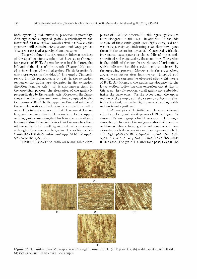
Figure 11 shows the grain structure after eight
passes of RUE. As observed in this �gure, grains aremore elongated in this case. In addition, in the sidesections of the sample, grains are highly elongated andvertically positioned, indicating that they have gonethrough the extrusion process. Compared with thefour passes case, grains in the middle of the sampleare re�ned and elongated at the same time. The grainsin the middle of the sample are elongated horizontallywhich indicates that this section has been a�ected bythe upsetting process. Moreover, in the areas wheregrains were coarse after four passes, elongated andre�ned grains can now be observed after eight passesof RUE. Additionally, the grains are elongated in thelower section, indicating that extrusion was at play inthis area. In this section, small grains are embeddedinside the large ones. On the other hand, the uppersection of the sample still shows some equiaxed grains,indicating that, even after eight passes, straining in thissection is not signi�cant.
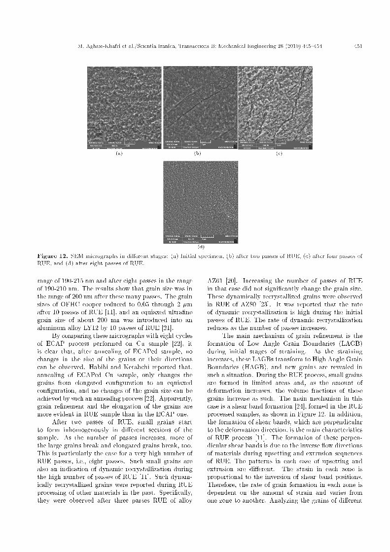
SEM analysis of the initial sample was performedafter two, four, and eight passes of RUE. Figure 12shows SEM micrographs for these cases. The imagesshow that, in line with the analyses elaborated in earliersections of this article, grains get smaller and lesselongated with the increasing number of passes. In fact,after eight passes of RUE, equiaxed grains were devel-oped. A cluster of very small grains is also observablein this case. The grain size after four passes was in the
Figure 11. Microstructures of the specimen after eight passes of RUE: (a) Top section, (b) middle section, (c) left side,(d) right side, and (e) bottom of the sample.
M. Aghaie-Khafri et al./Scientia Iranica, Transactions B: Mechanical Engineering 26 (2019) 445{454 451
Figure 12. SEM micrographs in di�erent stages: (a) Initial specimen, (b) after two passes of RUE, (c) after four passes ofRUE, and (d) after eight passes of RUE.
range of 190-215 nm and after eight passes in the rangeof 190-210 nm. The results show that grain size was inthe range of 200 nm after these many passes. The grainsizes of OFHC cooper reduced to 0.05 through 2 �mafter 10 passes of RUE [11], and an equiaxed ultra�negrain size of about 200 nm was introduced into analuminum alloy LY12 by 10 passes of RUE [21].
By comparing these micrographs with eight cyclesof ECAP process performed on Cu sample [22], itis clear that, after annealing of ECAPed sample, nochanges in the size of the grains or their directionscan be observed. Habibi and Ketabchi reported that,annealing of ECAPed Cu sample, only changes thegrains from elongated con�guration to an equiaxedcon�guration, and no changes of the grain size can beachieved by such an annealing process [22]. Apparently,grain re�nement and the elongation of the grains aremore evident in RUE sample than in the ECAP one.
After two passes of RUE, small grains startto form inhomogenously in di�erent sections of thesample. As the number of passes increases, more ofthe large grains break and elongated grains break, too.This is particularly the case for a very high number ofRUE passes, i.e., eight passes. Such small grains arealso an indication of dynamic recrystallization duringthe high number of passes of RUE [11]. Such dynam-ically recrystallized grains were reported during RUEprocessing of other materials in the past. Speci�cally,they were observed after three passes RUE of alloy
AZ61 [20]. Increasing the number of passes of RUEin that case did not signi�cantly change the grain size.These dynamically recrystallized grains were observedin RUE of AZ80 [23]. It was reported that the rateof dynamic recrystallization is high during the initialpasses of RUE. The rate of dynamic recrystallizationreduces as the number of passes increases.
The main mechanism of grain re�nement is theformation of Low Angle Grain Boundaries (LAGB)during initial stages of straining. As the strainingincreases, these LAGBs transform to High Angle GrainBoundaries (HAGB), and new grains are revealed insuch a situation. During the RUE process, small grainsare formed in limited areas and, as the amount ofdeformation increases, the volume fractions of thesegrains increase as such. The main mechanism in thiscase is a shear band formation [24], formed in the RUEprocessed samples, as shown in Figure 12. In addition,the formation of shear bands, which are perpendicularto the deformation direction, is the main characteristicsof RUE process [11]. The formation of these perpen-dicular shear bands is due to the inverse ow directionsof materials during upsetting and extrusion sequencesof RUE. The patterns in each case of upsetting andextrusion are di�erent. The strain in each zone isproportional to the inversion of shear band positions.Therefore, the rate of grain formation in each zone isdependent on the amount of strain and varies fromone zone to another. Analyzing the grains of di�erent
452 M. Aghaie-Khafri et al./Scientia Iranica, Transactions B: Mechanical Engineering 26 (2019) 445{454
passes of RUE reveals that only large grains can betransformed. In fact, after the formation of small grainsdue to dynamic recrystallization, more deformationonly changes large grains. The small grains in sucha situation do not change by increasing the amountof strain. Only when all grains are in the same size,small grains start to deform, mostly through slip orrotation mechanisms. The dislocations formed duringthe early stages of RUE passes can be canceled out athigher amount of straining. Re�ning the grains makesa uniform strength in di�erent sections of the specimenafter a high number of passes of RUE. Therefore,once the grain size distribution reaches a certain level,increasing the straining does not increase the strengthof the specimen.
3.2.2. ETMB modelIn a metal forming process, when the strain pathis reversed, dislocations with the opposite e�ect aregenerated. This is specially the case for the RUEprocess as the successive upsetting and extrusion wherethe material ows in an orthogonal direction duringupsetting and extrusion. In this situation, there is agreat chance that dislocations may cancel out at higheramount of strain and during high number of passes,which leads to the reduction of dislocation densityand the hardness of the specimen at high number ofpasses, i.e., eight passes of RUE. This re�nement of thestructure during severe plastic deformation has beenexplained by ETMB model. The main components ofthe ETMB model were the evolution equations for thedislocation densities in the cell walls and cell interior,determining the deformation process. This model con-siders the re�ned grains as a form of inside cells and theboundaries of the cells. Enikeev modi�ed the ETMBmodel by assuming that dislocation generation startsin the cell boundaries, and their annihilation occursin both inside the cells and the boundaries [25]. Themodi�ed ETMB, unlike the ETMB model that predictsthe saturation of the dislocations, predicts that the dis-location density initially increases, reaches a maximum,and, �nally, reduces rapidly to a constant level [11].
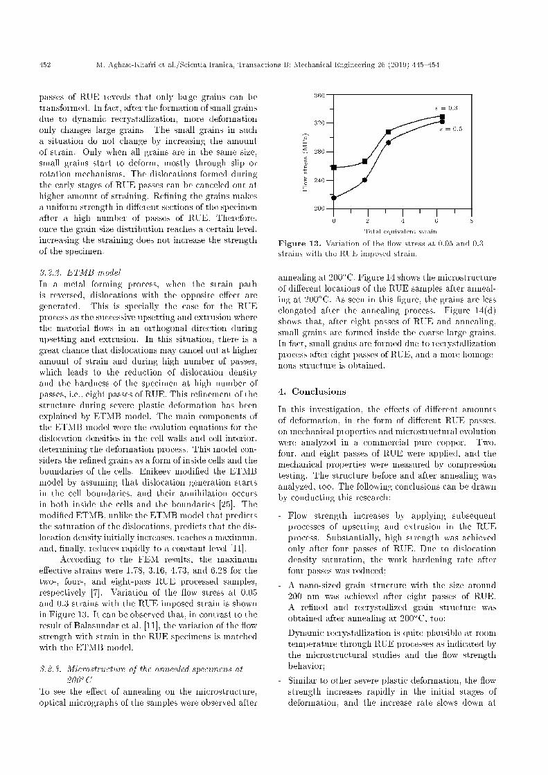
According to the FEM results, the maximume�ective strains were 1.78, 3.16, 4.73, and 6.28 for thetwo-, four-, and eight-pass RUE processed samples,respectively [7]. Variation of the ow stress at 0.05and 0.3 strains with the RUE imposed strain is shownin Figure 13. It can be observed that, in contrast to theresult of Balasundar et al. [11], the variation of the owstrength with strain in the RUE specimens is matchedwith the ETMB model.
3.2.3. Microstructure of the annealed specimens at200�C
To see the e�ect of annealing on the microstructure,optical micrographs of the samples were observed after
Figure 13. Variation of the ow stress at 0.05 and 0.3strains with the RUE imposed strain.
annealing at 200�C. Figure 14 shows the microstructureof di�erent locations of the RUE samples after anneal-ing at 200�C. As seen in this �gure, the grains are lesselongated after the annealing process. Figure 14(d)shows that, after eight passes of RUE and annealing,small grains are formed inside the coarse large grains.In fact, small grains are formed due to recrystallizationprocess after eight passes of RUE, and a more homoge-nous structure is obtained.
4. Conclusions
In this investigation, the e�ects of di�erent amountsof deformation, in the form of di�erent RUE passes,on mechanical properties and microstructural evolutionwere analyzed in a commercial pure copper. Two,four, and eight passes of RUE were applied, and themechanical properties were measured by compressiontesting. The structure before and after annealing wasanalyzed, too. The following conclusions can be drawnby conducting this research:
- Flow strength increases by applying subsequentprocesses of upsetting and extrusion in the RUEprocess. Substantially, high strength was achievedonly after four passes of RUE. Due to dislocationdensity saturation, the work hardening rate afterfour passes was reduced;
- A nano-sized grain structure with the size around200 nm was achieved after eight passes of RUE.A re�ned and recrystallized grain structure wasobtained after annealing at 200�C, too;
- Dynamic recrystallization is quite plausible at roomtemperature through RUE processes as indicated bythe microstructural studies and the ow strengthbehavior;
- Similar to other severe plastic deformation, the owstrength increases rapidly in the initial stages ofdeformation, and the increase rate slows down at

M. Aghaie-Khafri et al./Scientia Iranica, Transactions B: Mechanical Engineering 26 (2019) 445{454 453
Figure 14. Microstructures of the samples after annealing at 200�C for 20 min: (a) Initial specimen, (b) after two passesof RUE, (c) after four passes of RUE, and (d) after eight passes of RUE.
higher amount of deformation applied in the form ofa high number of passes;
- It has been found that the change of ow stress withthe e�ective strain imposed on the RUE specimen ismatched with the ETMB model.
References
1. Aghaie-Khafri, M. and Mahmudi, R. \Optimizing ho-mogenization parameters for better stretch formabilityin an Al-Mn-Mg alloy sheet", Mater. Sci. Eng. A, 399,pp. 173-180 (2005).
2. Saito, Y., Utsunomiya, H., Tsuji, N., and Sakai, T.\Novel ultra-high straining process for bulk materials-development of the accumulative roll-bonding (ARB)process", Acta Mater., 47, pp. 579-583 (1999).
3. Valiev, R.Z. and Langdon, T.G. \Developing SPDmethods for processing bulk nanostructured materialswith enhanced properties", Metals Mater. Int., 7, pp.413-420 (2001).
4. Yoon, E.Y., Lee, D.J., Park, B., Akbarpour, M.R.,Farvizi, M., and Kim, H.S. \Grain re�nement and ten-sile strength of carbon nanotube-reinforced Cu matrixnanocomposites processed by high-pressure torsion",Metals Mater. Int., 19, pp. 927-932 (2013).
5. Latypov, M.I., Lee, M.G., Beygelzimer, Y., Kulagin,R., and Kim, H.S. \Simple shear model of twistextrusion and its deviations", Metals. Mater. Int., 21,pp. 569-579 (2015).
6. Fatemi-Varzaneh, S.M. and Zarei-Hanzaki, A. \Accu-mulative back extrusion (ABE) processing as a novelbulk deformation method", Mater. Sci. Eng. A, 504,p. 104 (2009).
7. Binesh, B. and Aghaie-Khafri, M. \RUE-based semi-solid processing: Microstructure evolution and e�ec-tive parameters", Mater. Des., 95, pp. 268-286 (2016).
8. Zaharia, L., Comaneci, R., Chelariu, R., and Luca,D. \A new severe plastic deformation method byrepetitive extrusion and upsetting", Mater. Sci. Eng.A, 595, pp. 135-142 (2014).
9. Aizawa, T. and Tokimutu, K. \Bulk mechanical al-loying for productive processing of functional alloys",Mater. Sci. Forum, 312-314, pp. 13-22 (1999).
10. Raghu, I.B. \On the die design for repetitive upsetting-extrusion (RUE) process", Int. J. Mater. Form., 6, pp.289-301 (2013).
11. Balasundar, I., Ravi, K.R., and Raghu, T. \Strain soft-ening in oxygen free high conductivity (OFHC) coppersubjected to repetitive upsetting-extrusion (RUE) pro-cess", Mater. Sci. Eng., A583, pp. 114-122 (2013).
12. Balasundar, I. and Raghu, T. \Deformation behaviourof bulk materials during repetitive upsetting extrusion(RUE) process", Int. J. Mater. Form., 3, pp. 267-278(2010).
13. Balasundar, I. and Raghu, T. \On the die designrequirements of repetitive upsetting-extrusion (RUE)process", Int. J. Mater. Form., 6, pp. 289-301 (2013).

454 M. Aghaie-Khafri et al./Scientia Iranica, Transactions B: Mechanical Engineering 26 (2019) 445{454
14. Sheppard, T. Extrusion of Aluminum Alloys, SpringerScience+Business Media, B.V. (1999).
15. Balasundar, T. \Severe plastic deformation (SPD)using a combination of upsetting and extrusion", J.Metall. Eng. (ME), 2, pp. 130-139 (2013).
16. Balasundar, I. \Grain re�nement in OFHC Cu sub-jected to repetitive upsetting extrusion (RUE) pro-cess", Mater. Sci. Forum, 710, pp. 270-275 (2012).
17. Hosford, W.F. and Caddell, R.M., Metal Forming,Mechanics and Metallurgy, Fourth Edition, CambridgeUniv. Press (2011).
18. Ranaei, M.A. \Microstructure, mechanical and electri-cal properties of commercially pure copper deformedseverely by equal channel angular pressing", Int. J.Nanosci. Nanotech., 10, pp. 266-257 (2014).
19. Aghaie-Khafri, M. and Mahmudi, R. \The e�ect ofpreheating on the formability of an Al-Fe-Si alloysheet", J. Mater. Process. Technol., 169, pp. 38-43(2005).
20. XU, Y. \Microstructure and mechanical propertiesof AZ61 magnesium alloy prepared by repetitiveupsetting-extrusion", Trans. Nonferrous Metals Soc.,China, 25, pp. 381-388 (2015).
21. Lianxi, H., Yuping, L., Erde, W., and Yang, Y.\Ultra�ne grained structure and mechanical propertiesof a LY12 Al alloy prepared by repetitive upsetting-extrusion", Materi. Sci. Eng., A422, pp. 327-332(2006).
22. Habibi, A. and Ketabchi, M. \Enhanced propertiesof nano-grained pure copper by equal channel angularrolling and post-annealing", Mater. Des., 34, pp. 483-487 (2012).
23. Kommel, L. \Microstructure and properties develop-ment of copper during severe plastic deformation",Mater. Desi., 28, pp. 1221-2128 (2007).
24. Humphreys, F.J. and Hatherly, M., Recrystallizationand Related Annealing Phenomena, Elsevier Ltd.,(2004).
25. Enikeev, N.A. \Kinetic dislocation model of mi-crostructure evolution during severe plastic deforma-tion", Mater. Sci. Eng., A460, pp. 619-623 (2007).
Biographies
Mehrdad Aghaie-Khafri is a Professor of MaterialsScience and Engineering at K.N. Toosi University ofTechnology. His research interests are severe plasticdeformation, hot deformation, and mechanical behav-ior of materials.
Hashem Mousavi-Anijdan holds an MSc degree inMaterials Science and Engineering from Sharif Univer-sity of Technology in Iran and a PhD degree in the same�eld from McGill University in Canada. His researchinterests are focused on hot deformation of metals,microstructure & electron microscopy, and light alloys.
Meraaj Ahmadi earned his BSc in MetallurgicalEngineering from Hamedan University and MSc de-gree in Metal Forming from K.N. Toosi Universityof Technology. His MSc theses was investigation ofthe RUE processing of copper alloys. He is nowa project manager in the �eld of materials scienceand engineering and is interested in the sever plasticdeformation and mechanical behavior of materials.