Embed Size (px)
Citation preview

i
Name of the Lab: ENGINEERING GRAPHICS LAB
Name of the Faculty: N.Harini
Year/Sem : I-I &II
Academic Year: 2019-2020
Department of Mechanical Engineering
MALLA REDDY ENGINEERING COLLEGE
(Autonomous) (Approved by AICTE & Affiliated to JNTUH)
Maisammaguda, Dhulapally (Post via Kompally), Secunderabad-500 100
www.mrec.ac.in E-mail: [email protected]
Course File
ii
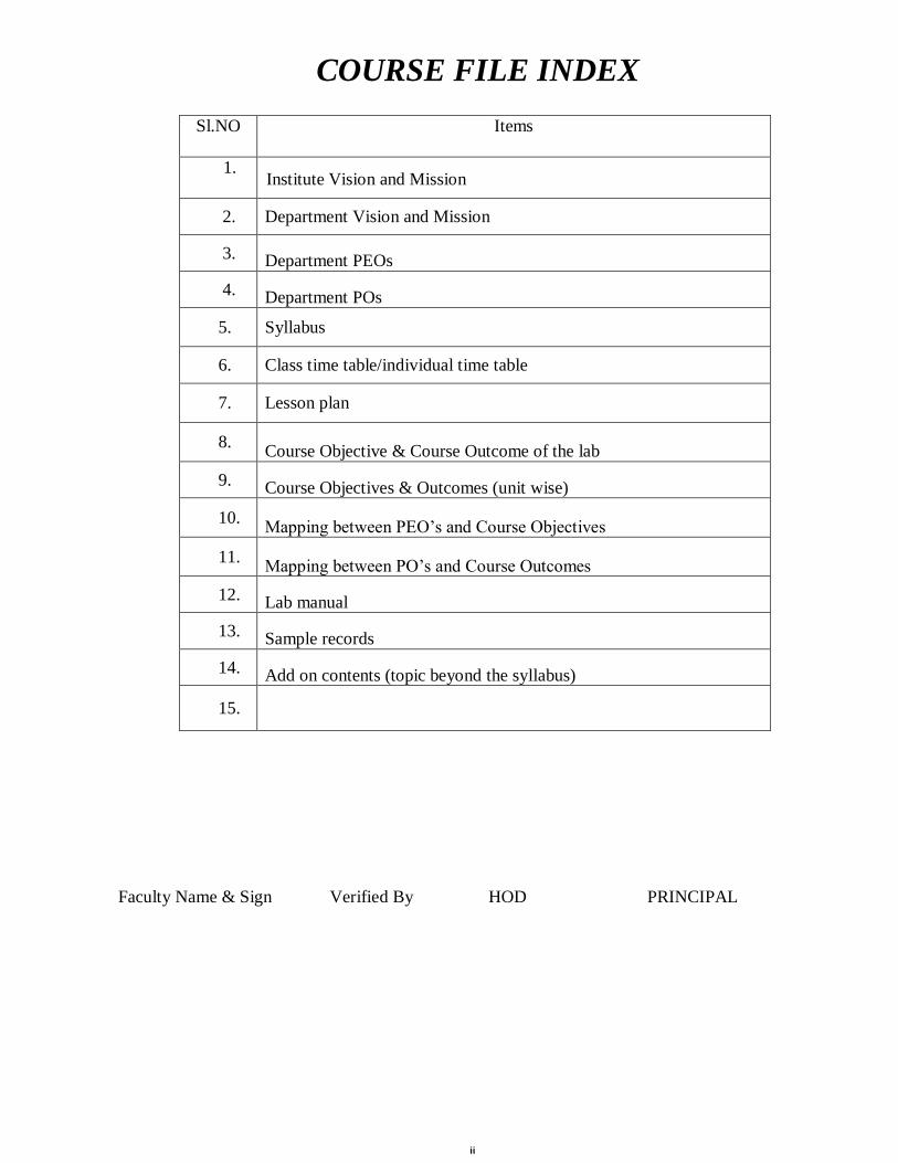
COURSE FILE INDEX
Sl.NO Items
1. Institute Vision and Mission
2. Department Vision and Mission
3. Department PEOs
4. Department POs
5. Syllabus
6. Class time table/individual time table
7. Lesson plan
8. Course Objective & Course Outcome of the lab
9. Course Objectives & Outcomes (unit wise)
10. Mapping between PEO’s and Course Objectives
11. Mapping between PO’s and Course Outcomes
12. Lab manual
13. Sample records
14. Add on contents (topic beyond the syllabus)
15.
Faculty Name & Sign Verified By HOD PRINCIPAL
iii
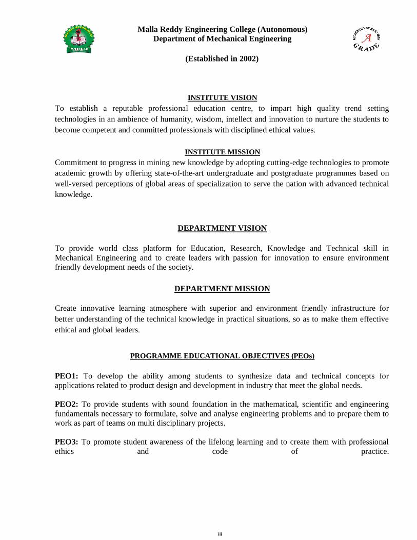
Malla Reddy Engineering College (Autonomous)
Department of Mechanical Engineering
(Established in 2002)
INSTITUTE VISION
To establish a reputable professional education centre, to impart high quality trend setting
technologies in an ambience of humanity, wisdom, intellect and innovation to nurture the students to
become competent and committed professionals with disciplined ethical values.
INSTITUTE MISSION
Commitment to progress in mining new knowledge by adopting cutting-edge technologies to promote
academic growth by offering state-of-the-art undergraduate and postgraduate programmes based on
well-versed perceptions of global areas of specialization to serve the nation with advanced technical
knowledge.
DEPARTMENT VISION
To provide world class platform for Education, Research, Knowledge and Technical skill in
Mechanical Engineering and to create leaders with passion for innovation to ensure environment
friendly development needs of the society.
DEPARTMENT MISSION
Create innovative learning atmosphere with superior and environment friendly infrastructure for
better understanding of the technical knowledge in practical situations, so as to make them effective
ethical and global leaders.
PROGRAMME EDUCATIONAL OBJECTIVES (PEOs)
PEO1: To develop the ability among students to synthesize data and technical concepts for
applications related to product design and development in industry that meet the global needs.
PEO2: To provide students with sound foundation in the mathematical, scientific and engineering
fundamentals necessary to formulate, solve and analyse engineering problems and to prepare them to
work as part of teams on multi disciplinary projects.
PEO3: To promote student awareness of the lifelong learning and to create them with professional
ethics and code of practice.
4
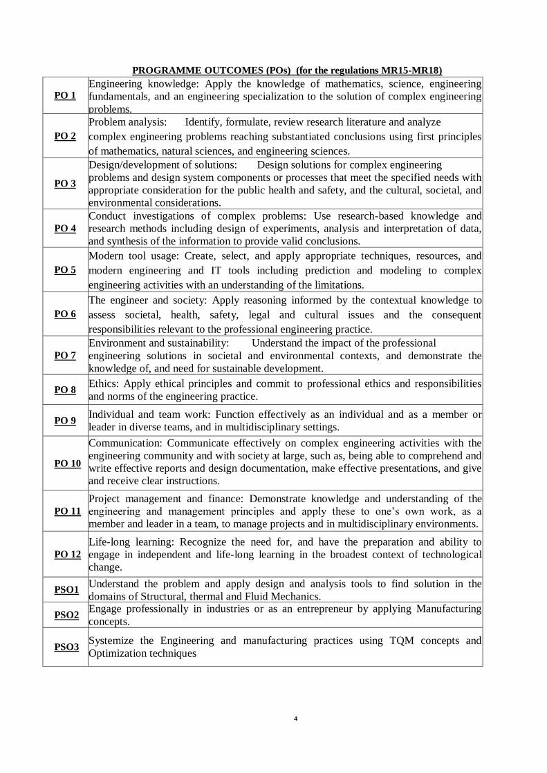
PROGRAMME OUTCOMES (POs) (for the regulations MR15-MR18)
PO 1 Engineering knowledge: Apply the knowledge of mathematics, science, engineering
fundamentals, and an engineering specialization to the solution of complex engineering
problems.
PO 2
Problem analysis: Identify, formulate, review research literature and analyze
complex engineering problems reaching substantiated conclusions using first principles
of mathematics, natural sciences, and engineering sciences.
PO 3
Design/development of solutions: Design solutions for complex engineering
problems and design system components or processes that meet the specified needs with
appropriate consideration for the public health and safety, and the cultural, societal, and
environmental considerations.
PO 4 Conduct investigations of complex problems: Use research-based knowledge and
research methods including design of experiments, analysis and interpretation of data,
and synthesis of the information to provide valid conclusions.
PO 5
Modern tool usage: Create, select, and apply appropriate techniques, resources, and
modern engineering and IT tools including prediction and modeling to complex
engineering activities with an understanding of the limitations.
PO 6
The engineer and society: Apply reasoning informed by the contextual knowledge to
assess societal, health, safety, legal and cultural issues and the consequent
responsibilities relevant to the professional engineering practice.
PO 7 Environment and sustainability: Understand the impact of the professional
engineering solutions in societal and environmental contexts, and demonstrate the
knowledge of, and need for sustainable development.
PO 8 Ethics: Apply ethical principles and commit to professional ethics and responsibilities
and norms of the engineering practice.
PO 9 Individual and team work: Function effectively as an individual and as a member or
leader in diverse teams, and in multidisciplinary settings.
PO 10
Communication: Communicate effectively on complex engineering activities with the
engineering community and with society at large, such as, being able to comprehend and
write effective reports and design documentation, make effective presentations, and give
and receive clear instructions.
PO 11
Project management and finance: Demonstrate knowledge and understanding of the
engineering and management principles and apply these to one’s own work, as a
member and leader in a team, to manage projects and in multidisciplinary environments.
PO 12 Life-long learning: Recognize the need for, and have the preparation and ability to
engage in independent and life-long learning in the broadest context of technological
change.
PSO1 Understand the problem and apply design and analysis tools to find solution in the
domains of Structural, thermal and Fluid Mechanics.
PSO2 Engage professionally in industries or as an entrepreneur by applying Manufacturing
concepts.
PSO3 Systemize the Engineering and manufacturing practices using TQM concepts and
Optimization techniques
5
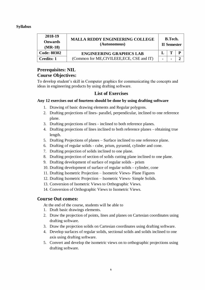
Syllabus
2018-19
Onwards
(MR-18)
MALLA REDDY ENGINEERING COLLEGE
(Autonomous)
B.Tech.
II Semester
Code: 80302 ENGINEERING GRAPHICS LAB
(Common for ME,CIVILEEE,ECE, CSE and IT)
L T P
Credits: 1 - - 2
Prerequisites: NIL
Course Objectives:
To develop student’s skill in Computer graphics for communicating the concepts and
ideas in engineering products by using drafting software.
List of Exercises
Any 12 exercises out of fourteen should be done by using drafting software
1. Drawing of basic drawing elements and Regular polygons.
2. Drafting projections of lines- parallel, perpendicular, inclined to one reference
plane.
3. Drafting projections of lines - inclined to both reference planes.
4. Drafting projections of lines inclined to both reference planes - obtaining true
length.
5. Drafting Projections of planes – Surface inclined to one reference plane.
6. Drafting of regular solids - cube, prism, pyramid, cylinder and cone.
7. Drafting projection of solids inclined to one plane.
8. Drafting projection of section of solids cutting plane inclined to one plane.
9. Drafting development of surface of regular solids - prism
10. Drafting development of surface of regular solids - cylinder, cone
11. Drafting Isometric Projection – Isometric Views- Plane Figures
12. Drafting Isometric Projection – Isometric Views- Simple Solids.
13. Conversion of Isometric Views to Orthographic Views.
14. Conversion of Orthographic Views to Isometric Views.
Course Out comes: At the end of the course, students will be able to
1. Draft basic drawings elements.
2. Draw the projection of points, lines and planes on Cartesian coordinates using
drafting software.
3. Draw the projection solids on Cartesian coordinates using drafting software.
4. Develop surfaces of regular solids, sectional solids and solids inclined to one
axis using drafting software.
5. Convert and develop the isometric views on to orthographic projections using
drafting software.
0
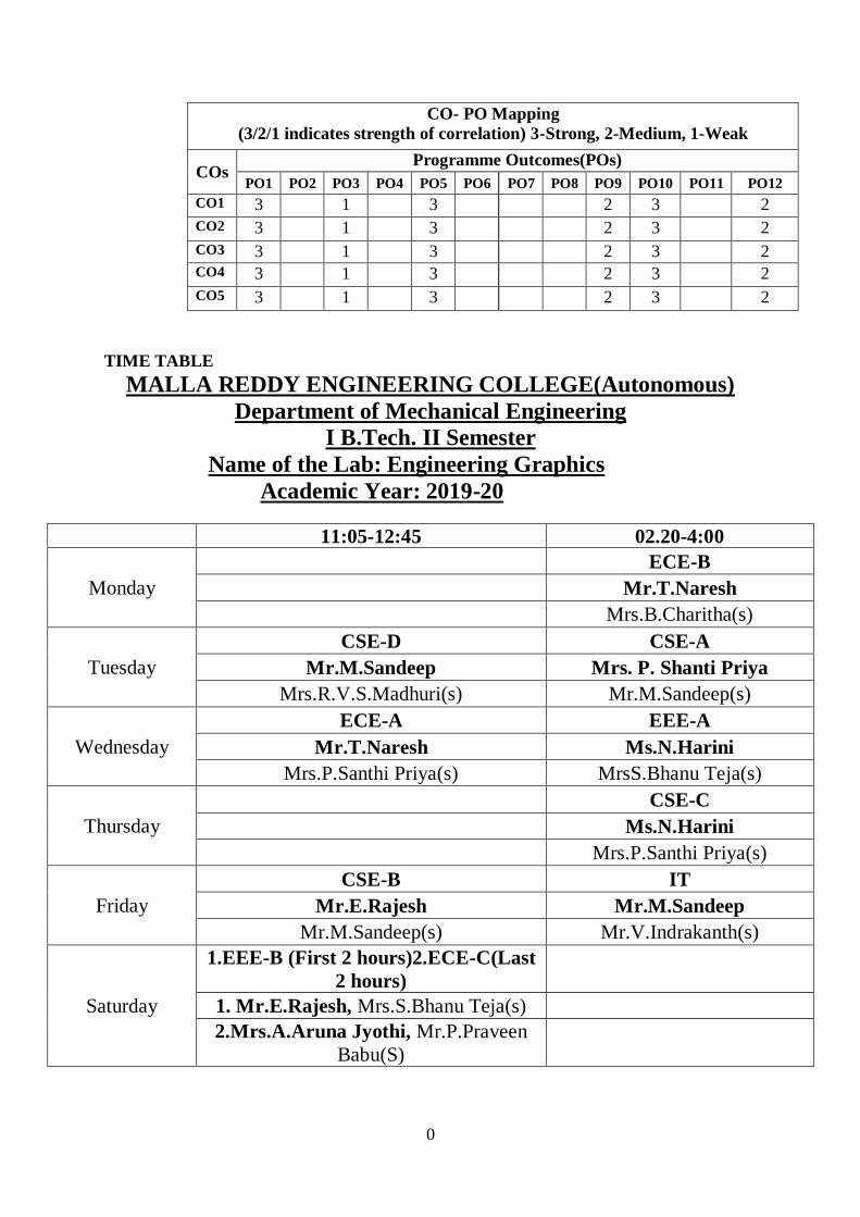
CO- PO Mapping
(3/2/1 indicates strength of correlation) 3-Strong, 2-Medium, 1-Weak
COs Programme Outcomes(POs)
PO1 PO2 PO3 PO4 PO5 PO6 PO7 PO8 PO9 PO10 PO11 PO12
CO1 3 1 3 2 3 2
CO2 3 1 3 2 3 2
CO3 3 1 3 2 3 2
CO4 3 1 3 2 3 2
CO5 3 1 3 2 3 2
TIME TABLE
MALLA REDDY ENGINEERING COLLEGE(Autonomous)
Department of Mechanical Engineering
I B.Tech. II Semester
Name of the Lab: Engineering Graphics
Academic Year: 2019-20
11:05-12:45 02.20-4:00
Monday
ECE-B
Mr.T.Naresh
Mrs.B.Charitha(s)
Tuesday
CSE-D CSE-A
Mr.M.Sandeep Mrs. P. Shanti Priya
Mrs.R.V.S.Madhuri(s) Mr.M.Sandeep(s)
Wednesday
ECE-A EEE-A
Mr.T.Naresh Ms.N.Harini
Mrs.P.Santhi Priya(s) MrsS.Bhanu Teja(s)
Thursday
CSE-C
Ms.N.Harini
Mrs.P.Santhi Priya(s)
Friday
CSE-B IT
Mr.E.Rajesh Mr.M.Sandeep
Mr.M.Sandeep(s) Mr.V.Indrakanth(s)
Saturday
1.EEE-B (First 2 hours)2.ECE-C(Last
2 hours)
1. Mr.E.Rajesh, Mrs.S.Bhanu Teja(s)
2.Mrs.A.Aruna Jyothi, Mr.P.Praveen
Babu(S)
1
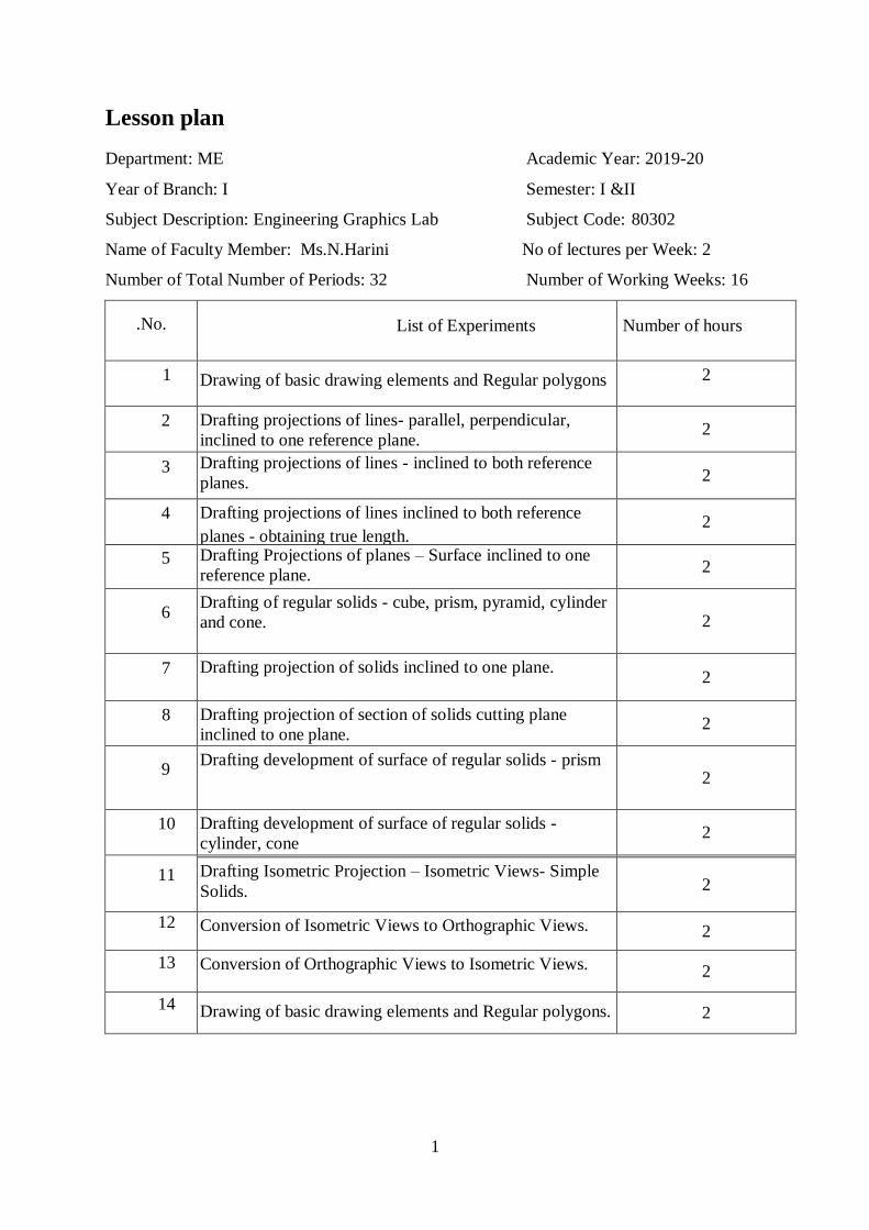
Lesson plan
Department: ME Academic Year: 2019-20
Year of Branch: I Semester: I &II
Subject Description: Engineering Graphics Lab Subject Code: 80302
Name of Faculty Member: Ms.N.Harini No of lectures per Week: 2
Number of Total Number of Periods: 32 Number of Working Weeks: 16
.No. List of Experiments Number of hours
1 Drawing of basic drawing elements and Regular polygons
.
2
2 Drafting projections of lines- parallel, perpendicular,
inclined to one reference plane. 2
3 Drafting projections of lines - inclined to both reference
planes. 2
4 Drafting projections of lines inclined to both reference
planes - obtaining true length. 2
5 Drafting Projections of planes – Surface inclined to one
reference plane. 2
6 Drafting of regular solids - cube, prism, pyramid, cylinder
and cone. 2
7 Drafting projection of solids inclined to one plane. 2
8 Drafting projection of section of solids cutting plane
inclined to one plane. 2
9 Drafting development of surface of regular solids - prism
2
10 Drafting development of surface of regular solids -
cylinder, cone 2
11 15. Drafting Isometric Projection –
Isometric Views- Plane Figures
2 Drafting Isometric Projection – Isometric Views- Simple
Solids. 2
12 Conversion of Isometric Views to Orthographic Views. 2
13 Conversion of Orthographic Views to Isometric Views. 2
14 Drawing of basic drawing elements and Regular polygons. 2
2
INTRODUCTION TO GRAPHICS PACKAGE
The engineering drawing has been and is an integral part of industry and it is a link between
engineering design and manufacturing. Information is quickly communicated in the form of
drawings prepared according to prescribed drafting standards.
What is Computer Aided Design?
The use of interactive graphics programs to develop 2D and 3D models, assemblies, part lists,
and dimensional drawings of various components, structures or objects with the help of a
computer is called Computer-Aided Design(CAD). The data generated by a CAD system can
be directly utilized by a CAM (Computer Aided Manufacturing) system. Thus CAD and
CAM are interrelated to each other.
Advantages of CAD:
1. Reduction of drafting labor.
2. Direct cost savings.
3. High accuracy (up to one millionth of a unit)
4. Improvement in the general flow of information through the company.
5. Evaluation of alternative designs.
6. Use of common parts in multiple products.
Before we design and manufacture any component, the object must be presented in the form
of drawings along with different views and dimensions. Further, the bill of materials etc.
must also be supplied. With the advent of computers and relevant software packages, the
drafting drifted from manual to computer aided drafting. The networking between the shop
floor sections and design sections makes it easier to share the data and information. The
modifications (in the drawings, materials or process of operation) if required, can be
discussed on line and can be implemented without any time lag. An attempt is made here to
introduce the graphics package in the following topics.
Starting Up AutoCAD
Select AUTOCAD from Start menu or picking the AutoCAD icon with a double click will
open the AutoCAD. If you choose to start AUTOCAD from start menu, select Start/
Programs/ AutoCAD.
3
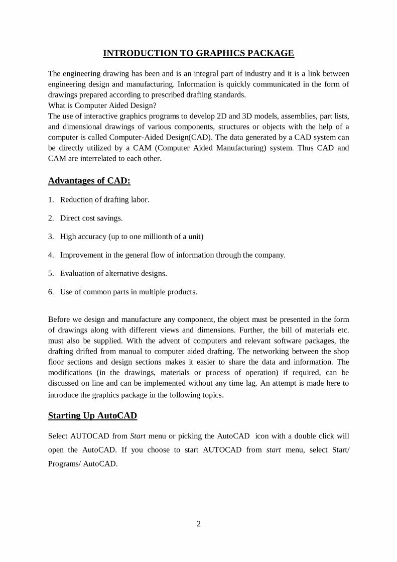
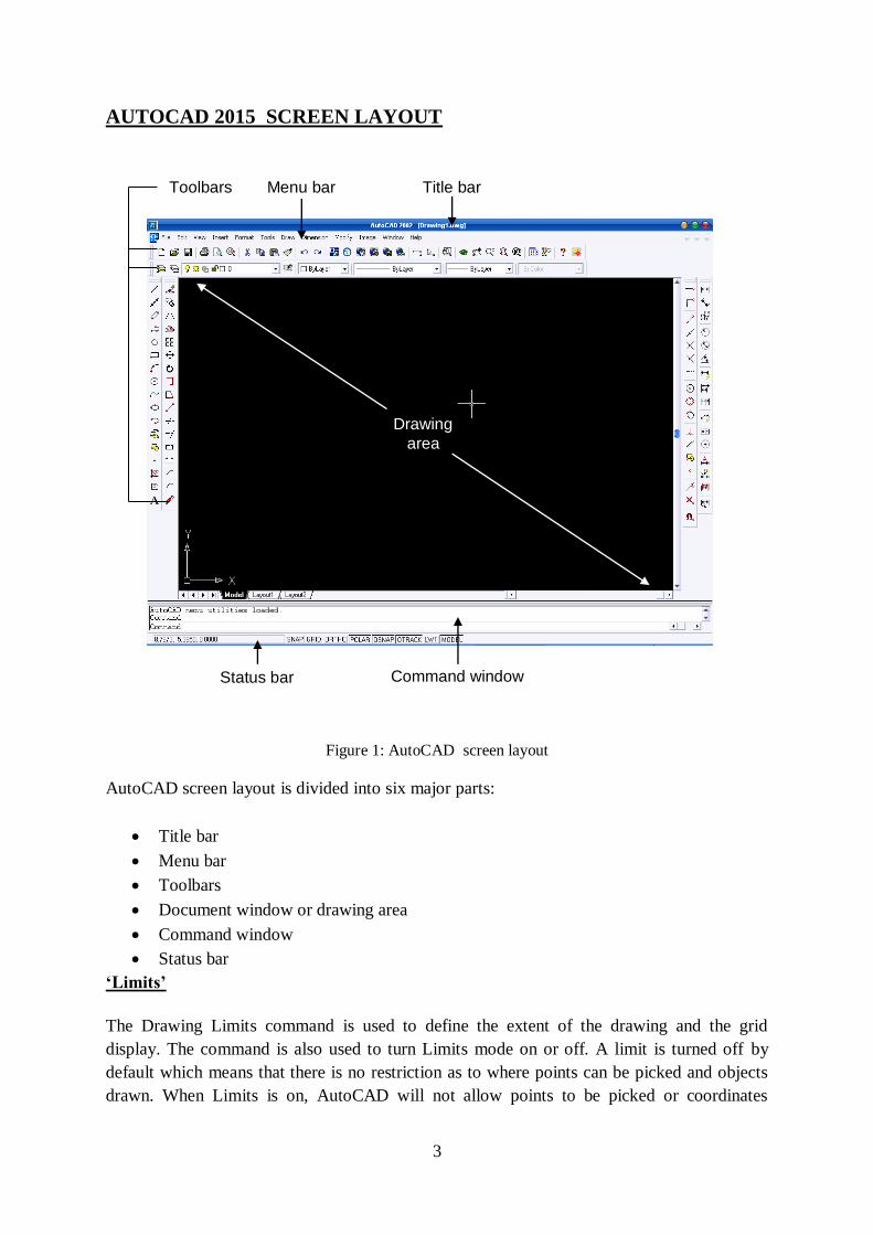
AUTOCAD 2015 SCREEN LAYOUT
Figure 1: AutoCAD screen layout
AutoCAD screen layout is divided into six major parts:
Title bar
Menu bar
Toolbars
Document window or drawing area
Command window
Status bar
‘Limits’
The Drawing Limits command is used to define the extent of the drawing and the grid
display. The command is also used to turn Limits mode on or off. A limit is turned off by
default which means that there is no restriction as to where points can be picked and objects
drawn. When Limits is on, AutoCAD will not allow points to be picked or coordinates
Drawing
area
Toolbars
Status bar Command window
Menu bar Title bar
4
entered at the command line which falls outside of the specified drawing limits. Usually the
scale of 1:1 (full scale) is used to represent the actual drawing size.
Example:
Command: limits <enter>
Reset model space limits.
ON/OFF/ lower left corner <0.0000,0.0000> : <enter>
Upper right corner <12.0000,9.0000> : 420,300<enter>
‘Snap’
Snap command allows picking points which lie on a regular grid. When Snap mode is turned,
the crosshairs will jump from one grid point to another as you move across the screen. This
makes it very easy to draw objects which have a regular shape. The Snap command is used to
set the snap spacing and to toggle Snap mode. Snap command can be used to turn Snap mode
on and off, but it is much more efficient to use the F9 function key on the keyboard or to
double-click "SNAP" on the status bar. Snap style can be set to either Isometric or Standard
(the default) using the "Style" option. The Standard style is used for almost all drawing
situations including detail drawings in Orthographic Projection. The Isometric style is
specifically to aid the creation of drawings in Isometric Projection.
Command: snap <enter>
Snap spacing or ON/OFF/Aspect/Rotate/Style: 10 <enter>
Snap spacing – default value for snap spacing in x and y direction are 1 unit. However it can
be changed to any number by setting the snap spacing.
Grid
The Grid command can be used to turn Grid mode on or off and to set the grid spacing (in
drawing units). When Grid mode is on, AutoCAD displays a regular pattern of dots on the
screen as a visual aid; it is equivalent to having a sheet of graph paper behind your drawing
on a drawing board. If the size of a drawing is A3 size, the suitable grid spacing is about 10
units.
Example:
The grid command will produce;
Command: Grid <enter>
Grid spacing <x> or ON/OFF/Aspect/ <0.000>: 10 <enter>
Units
5
Units command can be used to control the accuracy of drawing. There are several formats
that available for determination of spacing and measurement style.
Command: Units <enter>
Measurement unit system
1. Scientific 1.55E + 01
2. Decimal 15.50
3. Engineering 1’ – 3.50”
4. Architectural 1 – ¾”
5. Fractional 15 ½
Enter selection :< choose the coordinate format (1-5) and press enter>
Numbers of digits to right of decimal point (0-8) <4> : <value><enter>
After define the unit spacing unit, determine the angle measurement system.
Angle measurement system
1. Decimal degree 45.0000
2. Degree/minute/second 45d0’00”
3. Grads 50.0000g
4. Radian 0.7854r
5. Surveyor’s unit N45d0’0”E
Enter selection: <Value> <Enter>
Number of fractional places for displaying angle <8> : <Enter>
Exercises of using limits, snap and grid in a drawing
Command: limits <enter>
ON/OFF/ lower left corner <0.0000, 0.0000>: 0,0 <enter>
Limits at upper left corner is setting to A4 size paper
Command: grid <enter>
Grid spacing: 10 <enter>
Command: snap <enter>
Snap spacing: 10 <enter>
Command: Zoom <enter>
All/Extend/……/Scale: All <enter>
‘Zoom All’ command will change the drawing limit to A4 size paper.
THE FUNCTION KEYS
6
Many of the modes in AutoCAD can be controlled quickly using the keyboard function keys.
In most cases this is quicker than using a pull-down or the command line.
FI (dos) / F2 (windows) – Graphic screen or text screen
This key clears half of the screen and displays the HELP menu. Pressing F2 in the middle of
a drawing will remove the drawing from the screen and display a written list of the command
that were used to generate the drawing.
F6 – Coordinate mode
The coordinate display can be seen on the status of the line. Key F6 will switch the
coordinated display on or off.
F7 – Grid mode
The F7 key is used to toggle grid mode on and off. When grid mode is on a grid of dots is
shown on the screen as a drawing aid.
F8 – Ortho mode
The F8 key on the keyboard can be used to toggle Ortho (orthogonal) mode on and off. When
Ortho mode is on AutoCAD will only allow to draw either vertical or horizontal lines.
F9 – Snap mode
The F9 key can be used to toggle Snap mode on and off. Snap makes the crosshairs jump to
points on a defined grid.
COORDINATE SYSTEMS
(1) Absolute Coordinates
The Absolute coordinate method is based on specifying the location of a point by providing
its distances from two intersecting perpendicular axes in a 2D plane or from three intersecting
perpendicular planes for 3D space. Points are located by absolute coordinates in relation to
the origin. In AutoCAD, by default the origin (0,0) is located at the lower left corner of the
drawing.
(2) Relative Coordinates
In the relative coordinate method of construction each of the coordinates are entered relative
to the last set – i.e. including the distance from the last set. To differentiate between absolute
and relative entry, @ is entered before the figures of the coordinate point relative to the last
point. Example: @4,2
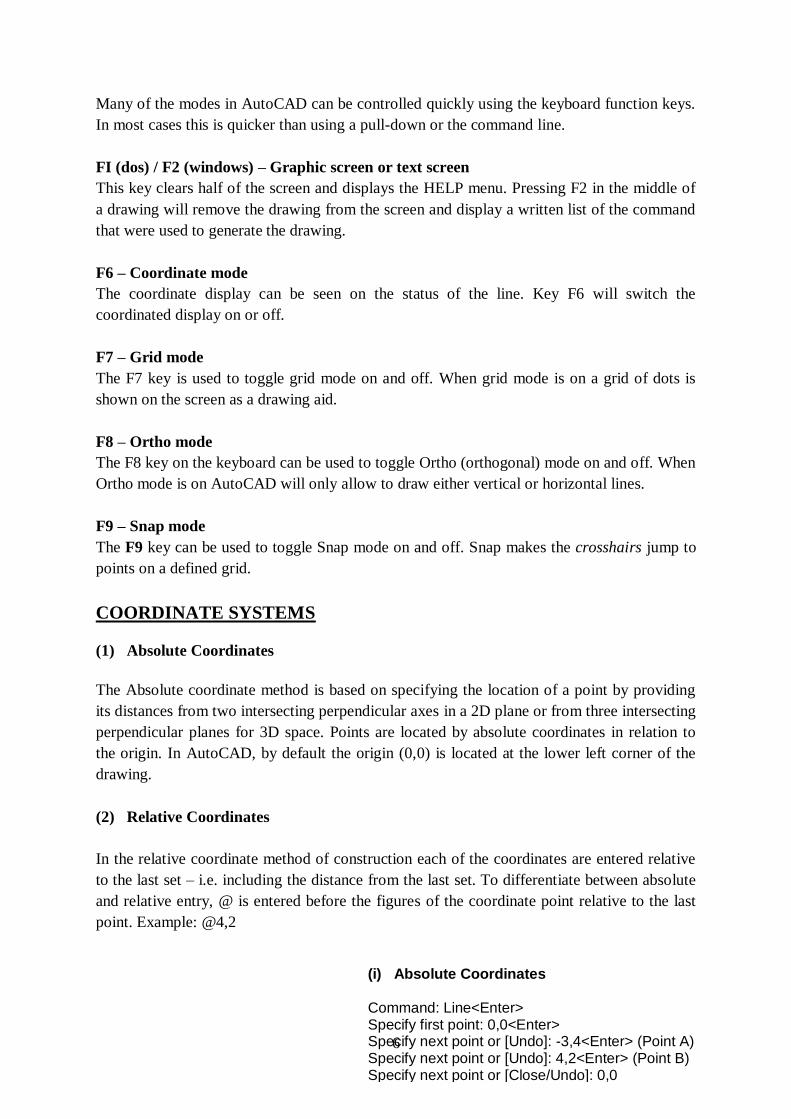
(i) Absolute Coordinates
Command: Line<Enter> Specify first point: 0,0<Enter> Specify next point or [Undo]: -3,4<Enter> (Point A) Specify next point or [Undo]: 4,2<Enter> (Point B) Specify next point or [Close/Undo]: 0,0
7
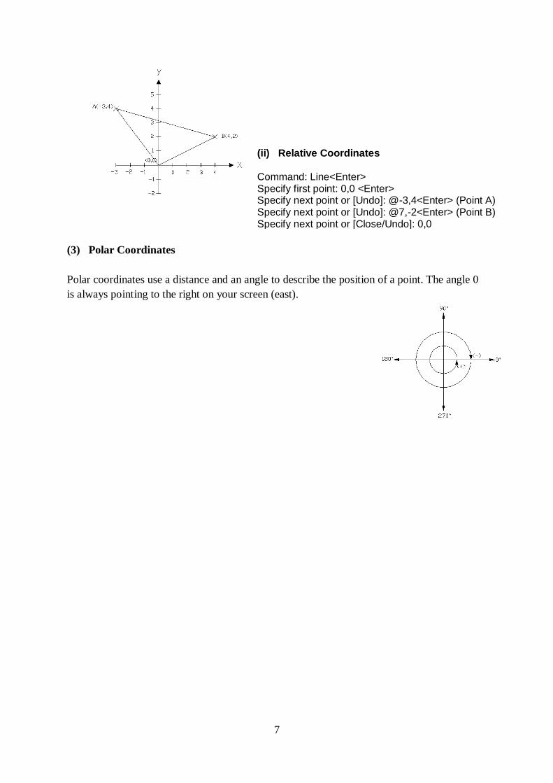
(3) Polar Coordinates
Polar coordinates use a distance and an angle to describe the position of a point. The angle 0
is always pointing to the right on your screen (east).
(ii) Relative Coordinates
Command: Line<Enter> Specify first point: 0,0 <Enter> Specify next point or [Undo]: @-3,4<Enter> (Point A) Specify next point or [Undo]: @7,-2<Enter> (Point B) Specify next point or [Close/Undo]: 0,0
8
EXERCISE-1
AIM: Draw basic drawing elements using AutoCAD
PROCEDURE:
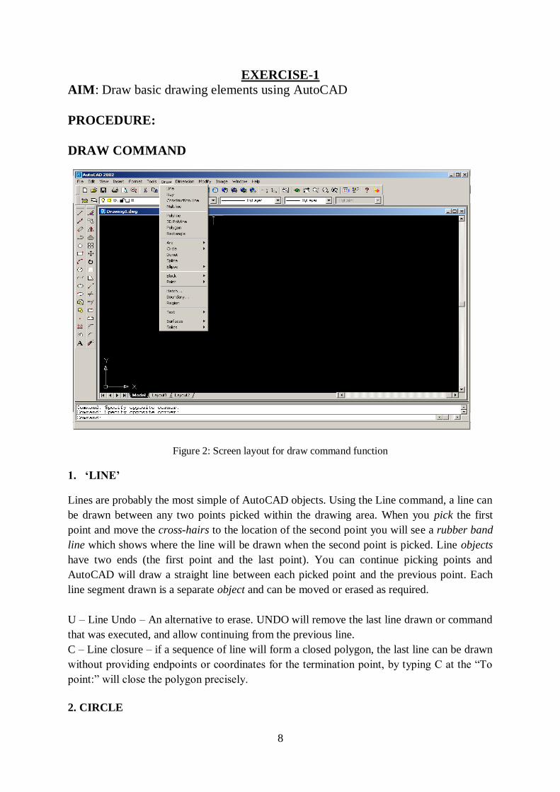
DRAW COMMAND
Figure 2: Screen layout for draw command function
1. ‘LINE’
Lines are probably the most simple of AutoCAD objects. Using the Line command, a line can
be drawn between any two points picked within the drawing area. When you pick the first
point and move the cross-hairs to the location of the second point you will see a rubber band
line which shows where the line will be drawn when the second point is picked. Line objects
have two ends (the first point and the last point). You can continue picking points and
AutoCAD will draw a straight line between each picked point and the previous point. Each
line segment drawn is a separate object and can be moved or erased as required.
U – Line Undo – An alternative to erase. UNDO will remove the last line drawn or command
that was executed, and allow continuing from the previous line.
C – Line closure – if a sequence of line will form a closed polygon, the last line can be drawn
without providing endpoints or coordinates for the termination point, by typing C at the “To
point:” will close the polygon precisely.
2. CIRCLE
9
The Circle command is used to draw circles. There are a number of ways to define the circle:
- Center and Radius or Diameter – The default method of drawing a circle is to enter
the center point and radius or diameter.
- Two point Circles – Drawing a two-point circle can be useful if the diameter is
known, but the center point is not.
- Three – Point Circles – If certain points of circle are known by entering any three
points.
- Tangent, Tangent, and Radius – A circle may be drawn tangent to existing features
by selecting two features that the circle will be tangent to, and then specifying a
radius.
3. ARC
The Arc command allows you to draw an arc of a circle. There are numerous ways to define
an arc; the default method uses three pick points, a start point, a second point and an end
point.
- ‘3-point’.
- ‘Start, Cen, End, or ‘Cen, Start, End’ (Start, Center, End)
- ‘Start, Cen, Angle’ or ‘Cen, Start, Angle’ (Start, Center, Angle)
- ‘Start, Cen, Length’ or ‘Cen, Start, Length’ (Start, Center, Length)
- ‘Start, End, Angle’ (Start, End, Angle)
- ‘Start, End, Radius’ (Start, End, Radius)
- ‘Start, End, Dir’ (Start, End, Direction)
4. POINT
This particular command allows for creating point with different style and size.
Determination of style and size are provided on pull-down menu ‘Settings Point Style….’
5. POLYLINE - PL
The polyline refers to a single object with multiple connected straight-line and/or arc
segments.
6. DONUT
This command draws a solid donut shape. AutoCAD asks you to define the inside diameter i.e. the
diameter of the hole and then the outside diameter of the donut.
7. RECTANGLE
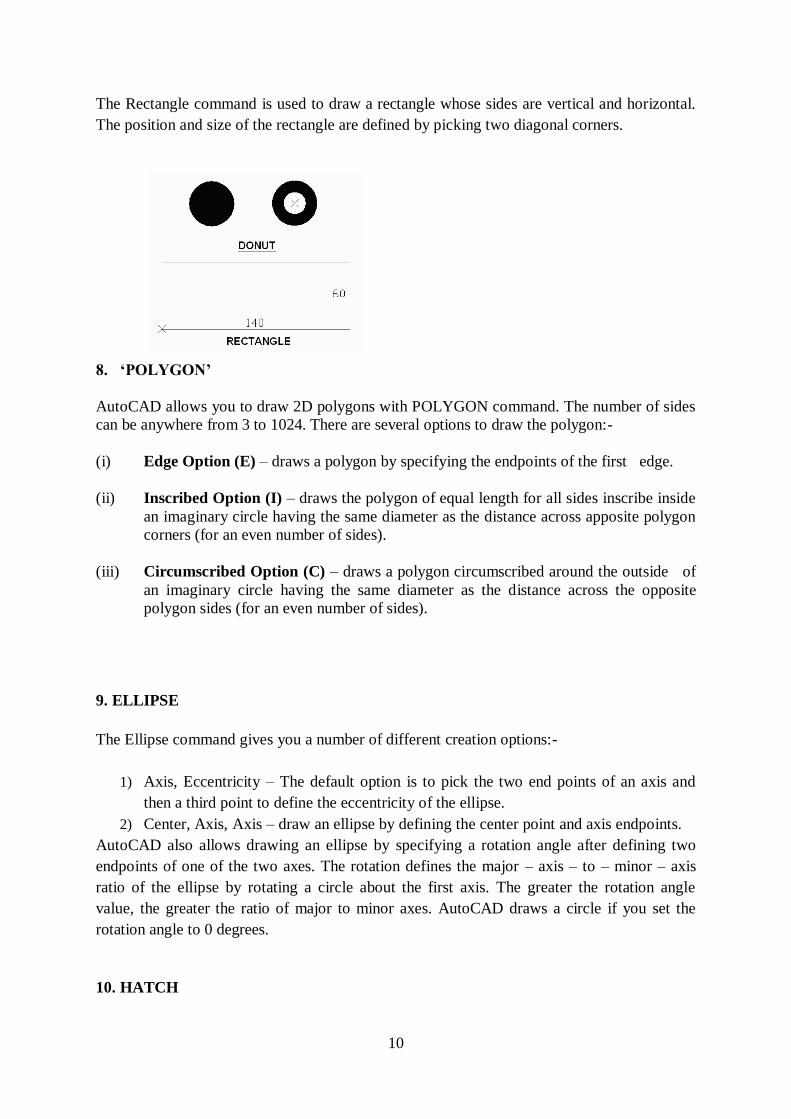
10
The Rectangle command is used to draw a rectangle whose sides are vertical and horizontal.
The position and size of the rectangle are defined by picking two diagonal corners.
8. ‘POLYGON’
AutoCAD allows you to draw 2D polygons with POLYGON command. The number of sides
can be anywhere from 3 to 1024. There are several options to draw the polygon:-
(i) Edge Option (E) – draws a polygon by specifying the endpoints of the first edge.
(ii) Inscribed Option (I) – draws the polygon of equal length for all sides inscribe inside
an imaginary circle having the same diameter as the distance across apposite polygon
corners (for an even number of sides).
(iii) Circumscribed Option (C) – draws a polygon circumscribed around the outside of
an imaginary circle having the same diameter as the distance across the opposite
polygon sides (for an even number of sides).
9. ELLIPSE
The Ellipse command gives you a number of different creation options:-
1) Axis, Eccentricity – The default option is to pick the two end points of an axis and
then a third point to define the eccentricity of the ellipse.
2) Center, Axis, Axis – draw an ellipse by defining the center point and axis endpoints.
AutoCAD also allows drawing an ellipse by specifying a rotation angle after defining two
endpoints of one of the two axes. The rotation defines the major – axis – to – minor – axis
ratio of the ellipse by rotating a circle about the first axis. The greater the rotation angle
value, the greater the ratio of major to minor axes. AutoCAD draws a circle if you set the
rotation angle to 0 degrees.
10. HATCH
11
Hatch patterns are repetitive patterns of lines, dots, and other symbols used to represent a
surface or specific material. Hatch patterns are used on sections and details, although to
shows the plan views and elevations.
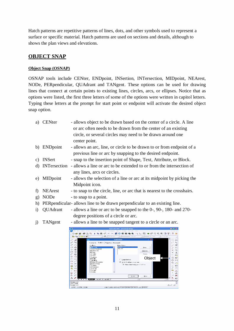
OBJECT SNAP
Object Snap (OSNAP)
OSNAP tools include CENter, ENDpoint, INSertion, INTersection, MIDpoint, NEArest,
NODe, PERpendicular, QUAdrant and TANgent. These options can be used for drawing
lines that connect at certain points to existing lines, circles, arcs, or ellipses. Notice that as
options were listed, the first three letters of some of the options were written in capitol letters.
Typing these letters at the prompt for start point or endpoint will activate the desired object
snap option.
a) CENter - allows object to be drawn based on the center of a circle. A line
or arc often needs to be drawn from the center of an existing
circle, or several circles may need to be drawn around one
center point.
b) ENDpoint - allows an arc, line, or circle to be drawn to or from endpoint of a
previous line or arc by snapping to the desired endpoint.
c) INSert - snap to the insertion point of Shape, Text, Attribute, or Block.
d) INTersection - allows a line or arc to be extended to or from the intersection of
any lines, arcs or circles.
e) MIDpoint - allows the selection of a line or arc at its midpoint by picking the
Midpoint icon.
f) NEArest - to snap to the circle, line, or arc that is nearest to the crosshairs.
g) NODe - to snap to a point.
h) PERpendicular- allows line to be drawn perpendicular to an existing line.
i) QUAdrant - allows a line or arc to be snapped to the 0-, 90-, 180- and 270-
degree positions of a circle or arc.
j) TANgent - allows a line to be snapped tangent to a circle or an arc.
Object snap
Command
12
Figure 3: Screen layout for ‘object snap’ command
There are four basic methods of accessing the Osnaps:
1. The Osnaps are available from a flyout button on the Standard toolbar.
2. From the pull-down menu, ‘View’ -> Toolbars ‘Object Snap’.
3. Access the Osnaps from the cursor menu. Hold the Shift key down on the keyboard
and right-click the mouse to bring up the cursor menu. The menu appears at the
current cursor position.
4. Access the Osnaps from the keyboard by typing their abbreviated name. Example: If
choose ‘Center’, type CEN <Enter>.
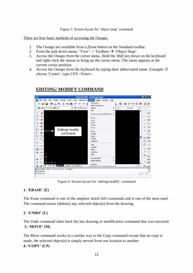
EDITING/ MODIFY COMMAND
Figure 4: Screen layout for ‘editing/modify’ command
1. ‘ERASE’ (E)
The Erase command is one of the simplest AutoCAD commands and is one of the most used.
The command erases (deletes) any selected object(s) from the drawing.
2. ‘UNDO’ (U)
The Undo command takes back the last drawing or modification command that was executed.
3. ‘MOVE’ (M)
The Move command works in a similar way to the Copy command except that no copy is
made, the selected object(s) is simply moved from one location to another.
4. ‘COPY’ (CP)
Editing/ modify command
13
The Copy command can be used to create one or more duplicates of any drawing object or
objects which have previously created. To copy more than one object, type M for ‘Multiple’
after selecting the object.
5. ‘MIRROR’
The mirror command will create a mirror image of any selected drawing elements along any
line of symmetry specified by the user. You’ll given the option of keeping or discarding the
original object prior to making the MIRROR permanent. If the object is being completed by
MIRROR, don’t delete the old object.
6. ‘ROTATE’
The rotate command rotates any selected objects about a defined point by the angle specified.
By default AutoCAD will rotate objects anticlockwise when an angle is entered.
7. ‘OFFSET’
Offset will make a copy of a line or series of selected lines by a specified distance in the
direction specified.
8. ‘EXTEND’
The extend command is similar to the trim command in how it functions, except it extends a selected line to a point of intersection of another selected object.
9. ‘TRIM’
The TRIM command is an extremely useful tool which will erase all parts of an object
beyond or within its intersection with another object. The command allows you to edit Lines,
Arcs, Circles, or Polylines using a cutting edge.
10. ‘BREAK’
The break command is identical to the above break at point command, except the break line
isn't as neat as when using the above command i.e the break point leaves a significant gap
between what is now two separate objects:
11 ‘FILLET’
The fillet command is very similar to the chamfer command above, except instead of creating
a straight line chamfer, AutoCAD creates a radius between the two points.
12. ‘CHAMFER’
The chamfer command will chamfer the intersection of two lines to a specified distance.
13 ‘STRETCH’
14
The STRETCH command allows you to elongate or shrink drawing entities. Thos can be
especially helpful when editing the shape and size of a floor plan to meet the changing needs.
Drawings made with Lines, Arcs, Traces, Solids, and Polylines can all be stretched.
14. ‘ARRAY’
The Array command will allow for multiple copies of an object or group of objects in
rectangular or circular (polar) patterns.
15. ‘SCALE’
The SCALE command will allow changing the size of an existing object or an entire drawing
base on scale factor.
SELECT OBJECTS
In addition to selecting objects to edit using the pick box, AutoCAD provides the options of
Window, Crossing, CPolygon, WPolygon, Fence, All, Last, Add, Remove, Previous and
Multiple to select an object for editing. Each of the following selection methods can be
entered at the Select objects: prompt for editing command.
1) Pickbox - only one object is selected at a time.
2) Window (W) – rather than selecting objects to edit one at a time, a group of entities may
be selected by surrounding them completely in a window.
3) Crossing (C) – The command process will be the same with as the Window option. Any
objects that lie entirely in the window will be edited. Any objects that are partially inside the
window also will be edited.
4) Previous (P) – All objects in a previous set.
5) Remove (R) – allow for the objects to be removed from the selection set.
6) Add (A) – allow for additional objects to be added to the selection set.
7) Last (L) – allows the most recently created object to be selected for editing.
8) Fence (F) – allows the long rows or columns to be edited.
9) Window Polygon (WP) – allows for selecting points to form a polygon around objects to
be edited.
10) Crossing Polygon (CP) – edit all objects that are in or cross the polygon.
11) All – select all objects in drawing
DISPLAY COMMAND
‘Zoom’ (Z)
15
Zooming the drawing area and its contents to different sizes is a very important part of the
construction of drawings. This ability provides a close-up view for better accuracy and detail
or a distant view to get the whole picture.
a. ‘Zoom’ All (A) – zoom the drawing so that it is at its full extent, with its edges
touching the edges of the drawing area.
b. ‘Zoom’ Center (C) – select a new view by specifying its center point and the
magnification value or height of the view in current units.
c. ‘Zoom’ Dynamic (D) – provides a quick and easy method to move to another view of
drawing. With Zoom Dynamic, you can see the entire drawing and then simply select the
location and size of the next view by means of cursor manipulations.
d. ‘Zoom’ Extend (E) – lets you see the entire drawing on screen. Unlike the All option,
the Extents Option uses only the drawing extents and not the drawing limits.
e. ‘Zoom’ Left (L) – display drawing on the bottom left of graphic screen and the object
zooming size is similar to ‘Zoom’ - Center.
f. ‘Zoom’ Previous (P) – displays the last displayed view.
g. ‘Zoom’ Window (W) – specify a smaller area of the part of the drawing being
currently displayed and have that portion fill the drawing area.
h. ‘Zoom’ Scale (X/XP) – display drawing on graphic layout base on scale or
magnification factor.
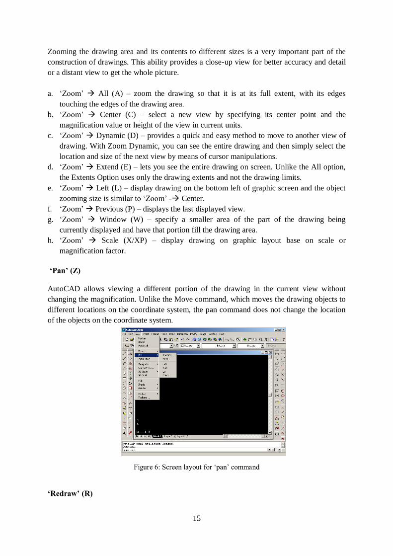
‘Pan’ (Z)
AutoCAD allows viewing a different portion of the drawing in the current view without
changing the magnification. Unlike the Move command, which moves the drawing objects to
different locations on the coordinate system, the pan command does not change the location
of the objects on the coordinate system.
Figure 6: Screen layout for ‘pan’ command
‘Redraw’ (R)
16
The REDRAW command removes the current screen display momentarily, and then replaces
the drawing. As the drawing is replaced, blip marks are removed from the drawing editor.
Lines that may have been partially erased while editing other entities also will be restored.
‘Viewres’ (V)
The resolution of arcs and circles is controlled by the VIEWRES command. Resolution refers
to the amount of detail that is represented when arcs and circles are drawn. The higher the
resolution, the more lines that are used and the smoother the arc or circle will appear.
LAYER (LA)
Layers are a way of managing, tidying and also controlling the visual layout of a drawing. A
whole section of a drawing can be turned on or off, or simply one aspect can be controlled -
text for example.
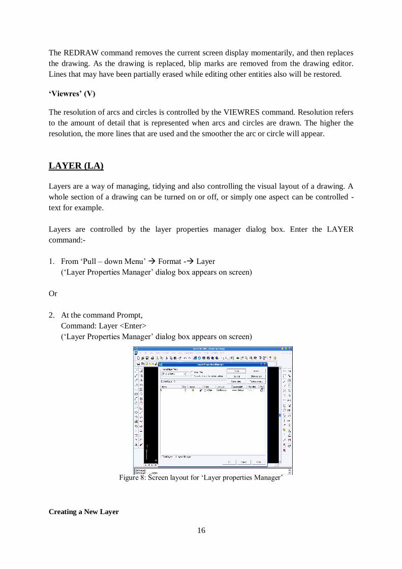
Layers are controlled by the layer properties manager dialog box. Enter the LAYER
command:-
1. From ‘Pull – down Menu’ Format - Layer
(‘Layer Properties Manager’ dialog box appears on screen)
Or
2. At the command Prompt,
Command: Layer <Enter>
(‘Layer Properties Manager’ dialog box appears on screen)
Figure 8: Screen layout for ‘Layer properties Manager’
Creating a New Layer
17
Once in the ‘Layer Properties Manager’ choose the ‘New’ button from the upper right hand
corner. The new layer now appears in ‘Layer Properties Manager’ dialog box.
After a layer has been created, colors and linetype can be assigned by layers. To alter the
color of a layer, pick the layer so that the layer name is highlighted. The color of each layer
can be altered by picking the color icon from the color list or by choosing Color from the
detail box. The linetype can be altered using methods similar to altering layer color.
Highlighting the name of the layer to be altered, and then selecting the linetype name will
display the Select Linetype dialog box. The dialog box can be used to load and select line
type.
Setting Layers On/Off
The entire new layers that have been created are set in the ON option. By setting a layer to
OFF, objects drawn on that layer will be invisible.
Thawing and Freezing Layers
Freeze – Open the Layer and Linetype Properties dialog box and select the layer that would
like to freeze, and pick the freeze button. The sun icon (Thaw) will be change to and icicle
(Freeze). Picking the OK button will activate the selection, restore the drawing screen, and
remove the objects on the selected layer from the display.
Thaw – The Thaw option of the LAYER command will allow for specified frozen layers to
be thawed. To thaw a layer that is frozen, open the Layer and Linetype Properties dialog box
and select the icicle icon of the layer to be thawed. As the icicle is picked, it will change to
the sun icon, indicating that the layer has been thawed. Picking the OK button will activate
the selection, restore the drawing screen and display the material on the layer that had been
frozen.
‘PROPERTIES’ – Modify/Change
MODIFY – The command can be used to control the properties of existing objects. The
command can be started by picking the Properties icon from the far right side of the Object
Properties toolbar, by selecting ‘Properties’ from the Modify pull-down menu, or by typing
DDMODIFY at the command prompt. Once the entity is selected, the Modify Line box is
displayed. The box allows for altering the Color, Layer, Linetype, Handle, Thickness, and
Ltscale.
CHANGE – The final command to be considered when setting linetype, color, or layers.
Each of the attributes related to layers can be altered within the LAYER command. When a
color of layer is changed from red to blue, all lines on the specified layer are become blue.
The CHANGE command will allow for only selected entities to be altered.
18
TEXT
Text is used to label the various components of the drawing and to create the necessary shop
or field notes needed for fabrication and construction of the design. AutoCAD includes a
large number of text fonts. Text can be stretched, compressed, obliqued, mirrored, or drawn
in a vertical column by applying a style. Each text string can be sized, rotated, and justified to
meet drawing needs. The Justify option allows placing text in one of the 14 available
justification points. AutoCAD prompts
The Style option of the TEXT commands are allows determining how text characters and
symbols appear, other than adjusting the usual height, slant, and angle of rotation. To specify
a text style from the Style option of the TEXT commands, it must have been defined by using
the STYLE command. In other words, the style command creates a new style or modifies an
existing style. AutoCAD displays the Text Style dialog box.
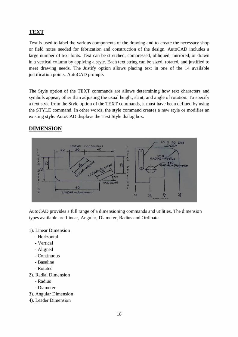
DIMENSION
AutoCAD provides a full range of a dimensioning commands and utilities. The dimension
types available are Linear, Angular, Diameter, Radius and Ordinate.
1). Linear Dimension
- Horizontal
- Vertical
- Aligned
- Continuous
- Baseline
- Rotated
2). Radial Dimension
- Radius
- Diameter
3). Angular Dimension
4). Leader Dimension
19
5). Ordinate Dimension
There are also other general utility, editing, and style-related commands and subcommands
that assist in drawing the correct dimensions quickly and with accuracy. AutoCAD provides a
comprehensive set of subdialog boxes accessible through the Dimension Style Manager
dialog box for creating new Dimension Style and managing existing ones. AutoCAD displays
the Dimension Style Manager dialog box.
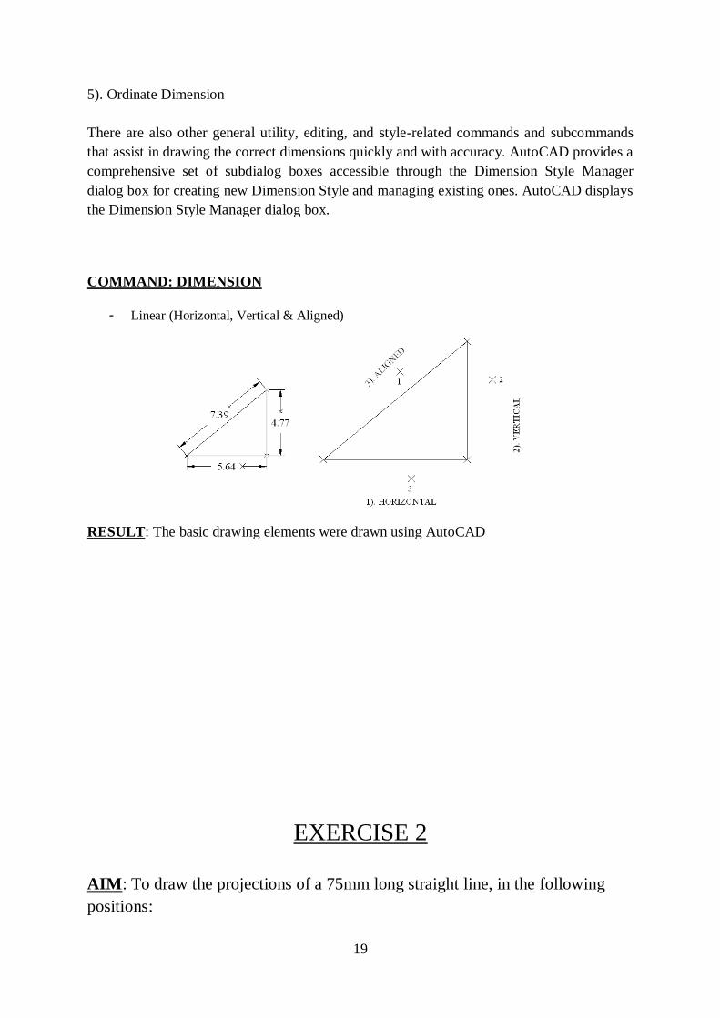
COMMAND: DIMENSION
- Linear (Horizontal, Vertical & Aligned)
RESULT: The basic drawing elements were drawn using AutoCAD
EXERCISE 2
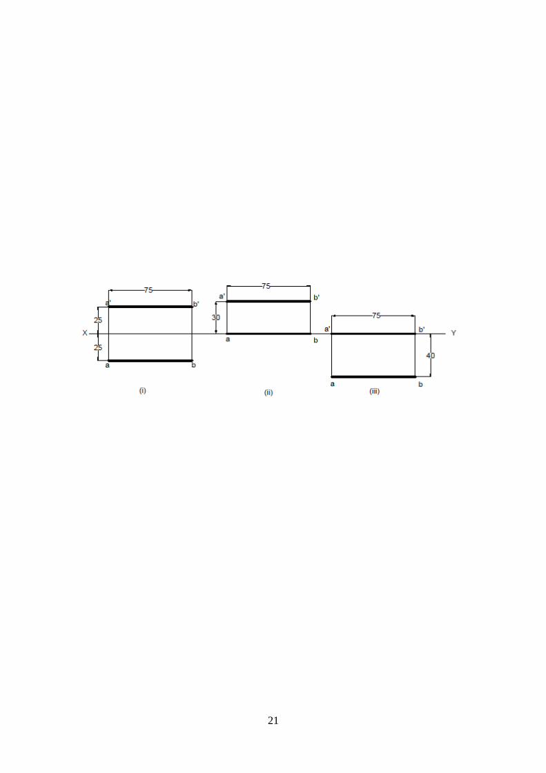
AIM: To draw the projections of a 75mm long straight line, in the following
positions:
20
(i) Parallel to both the H.P. and the V.P. and 25mm from each.
(ii) Parallel to and 30mm above the H.P. and in the V.P.
(iii) Parallel to and 40mm in front of the V.P. and in the H.P
PROCEDURE:
Case (i):
1. Draw a horizontal line XY.
2. Draw a line of length 75mm parallel to XY at a distance of 25mm above
it. Mark the ends as a’, b’. This is the FV.
3. Draw a line of length 75mm parallel to XY at a distance of 25mm below
it. Mark the ends as a, b. This is the TV.
Case (ii):
1. Draw a horizontal line XY.
2. Draw a line of length 75mm parallel to XY at a distance of 30mm above
it. Mark the ends as a’, b’. This is the FV.
3. Project the above line on XY. Mark the ends as a, b. This is the TV.
Case (iii):
1. Draw a horizontal line XY.
2. Draw a line of length 75mm parallel to XY at a distance of 40mm below
it. Mark the ends as a, b. This is the TV.
3. Project the above line on XY. Mark the ends as a’, b’. This is the FV.
RESULT: The required projections are obtained in AutoCAD.
21
22
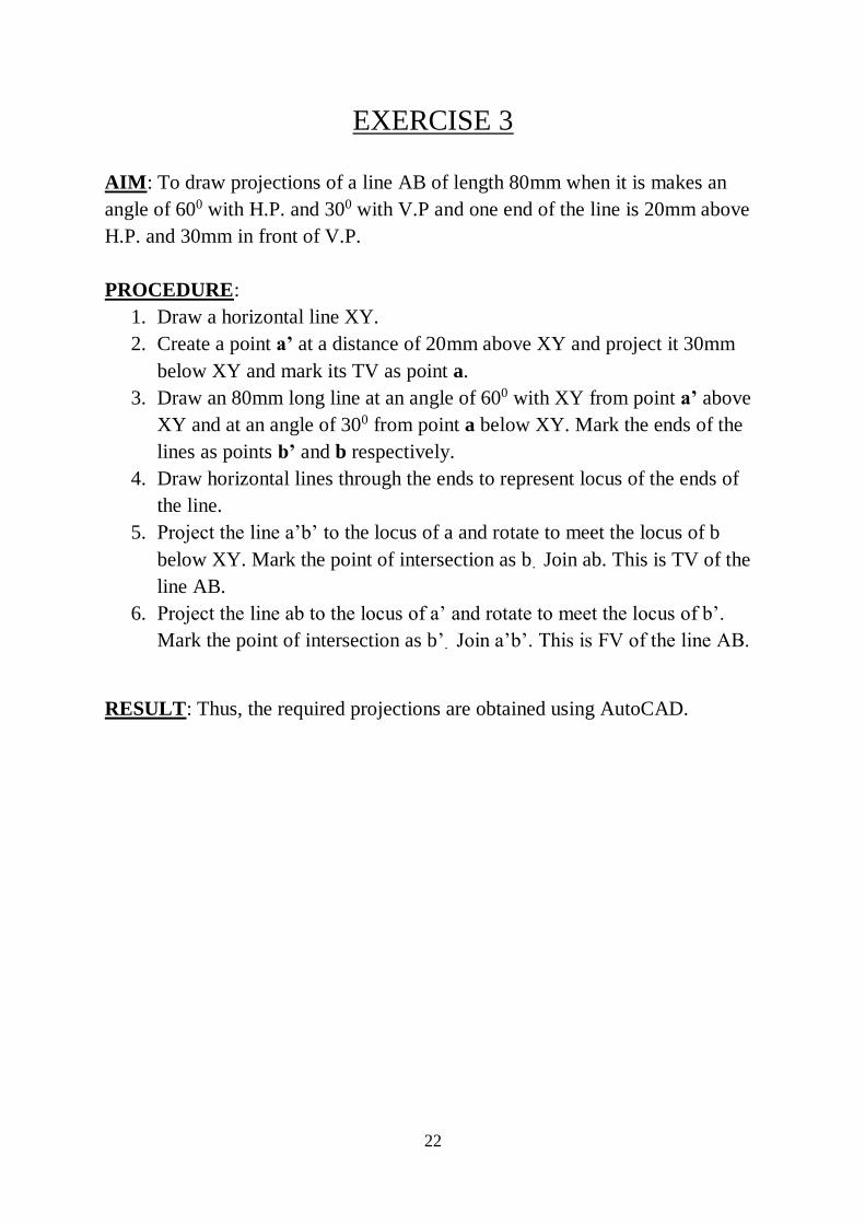
EXERCISE 3
AIM: To draw projections of a line AB of length 80mm when it is makes an
angle of 600 with H.P. and 300 with V.P and one end of the line is 20mm above
H.P. and 30mm in front of V.P.
PROCEDURE:
1. Draw a horizontal line XY.
2. Create a point a’ at a distance of 20mm above XY and project it 30mm
below XY and mark its TV as point a.
3. Draw an 80mm long line at an angle of 600 with XY from point a’ above
XY and at an angle of 300 from point a below XY. Mark the ends of the
lines as points b’ and b respectively.
4. Draw horizontal lines through the ends to represent locus of the ends of
the line.
5. Project the line a’b’ to the locus of a and rotate to meet the locus of b
below XY. Mark the point of intersection as b. Join ab. This is TV of the
line AB.
6. Project the line ab to the locus of a’ and rotate to meet the locus of b’.
Mark the point of intersection as b’. Join a’b’. This is FV of the line AB.
RESULT: Thus, the required projections are obtained using AutoCAD.
23
24
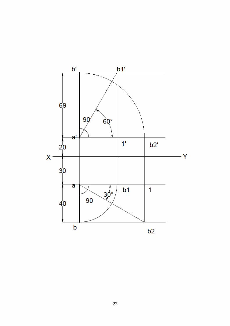
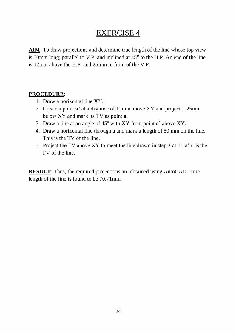
EXERCISE 4
AIM: To draw projections and determine true length of the line whose top view
is 50mm long; parallel to V.P. and inclined at 45⁰ to the H.P. An end of the line
is 12mm above the H.P. and 25mm in front of the V.P.
PROCEDURE:
1. Draw a horizontal line XY.
2. Create a point a’ at a distance of 12mm above XY and project it 25mm
below XY and mark its TV as point a.
3. Draw a line at an angle of 450 with XY from point a’ above XY.
4. Draw a horizontal line through a and mark a length of 50 mm on the line.
This is the TV of the line.
5. Project the TV above XY to meet the line drawn in step 3 at b’. a’b’ is the
FV of the line.
RESULT: Thus, the required projections are obtained using AutoCAD. True
length of the line is found to be 70.71mm.
25
26
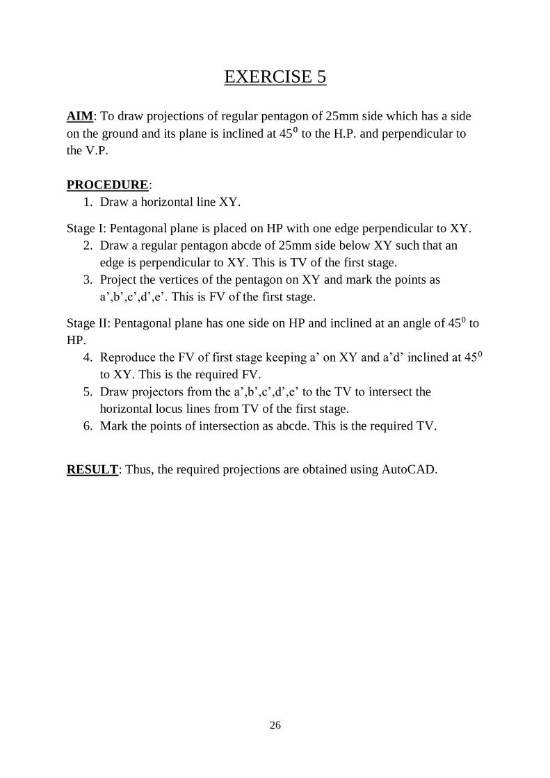
EXERCISE 5
AIM: To draw projections of regular pentagon of 25mm side which has a side
on the ground and its plane is inclined at 45⁰ to the H.P. and perpendicular to
the V.P.
PROCEDURE:
1. Draw a horizontal line XY.
Stage I: Pentagonal plane is placed on HP with one edge perpendicular to XY.
2. Draw a regular pentagon abcde of 25mm side below XY such that an
edge is perpendicular to XY. This is TV of the first stage.
3. Project the vertices of the pentagon on XY and mark the points as
a’,b’,c’,d’,e’. This is FV of the first stage.
Stage II: Pentagonal plane has one side on HP and inclined at an angle of 450 to
HP.
4. Reproduce the FV of first stage keeping a’ on XY and a’d’ inclined at 450
to XY. This is the required FV.
5. Draw projectors from the a’,b’,c’,d’,e’ to the TV to intersect the
horizontal locus lines from TV of the first stage.
6. Mark the points of intersection as abcde. This is the required TV.
RESULT: Thus, the required projections are obtained using AutoCAD.
27
28
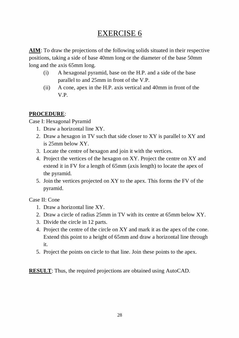
EXERCISE 6
AIM: To draw the projections of the following solids situated in their respective
positions, taking a side of base 40mm long or the diameter of the base 50mm
long and the axis 65mm long.
(i) A hexagonal pyramid, base on the H.P. and a side of the base
parallel to and 25mm in front of the V.P.
(ii) A cone, apex in the H.P. axis vertical and 40mm in front of the
V.P.
PROCEDURE:
Case I: Hexagonal Pyramid
1. Draw a horizontal line XY.
2. Draw a hexagon in TV such that side closer to XY is parallel to XY and
is 25mm below XY.
3. Locate the centre of hexagon and join it with the vertices.
4. Project the vertices of the hexagon on XY. Project the centre on XY and
extend it in FV for a length of 65mm (axis length) to locate the apex of
the pyramid.
5. Join the vertices projected on XY to the apex. This forms the FV of the
pyramid.
Case II: Cone
1. Draw a horizontal line XY.
2. Draw a circle of radius 25mm in TV with its centre at 65mm below XY.
3. Divide the circle in 12 parts.
4. Project the centre of the circle on XY and mark it as the apex of the cone.
Extend this point to a height of 65mm and draw a horizontal line through
it.
5. Project the points on circle to that line. Join these points to the apex.
RESULT: Thus, the required projections are obtained using AutoCAD.
29
30
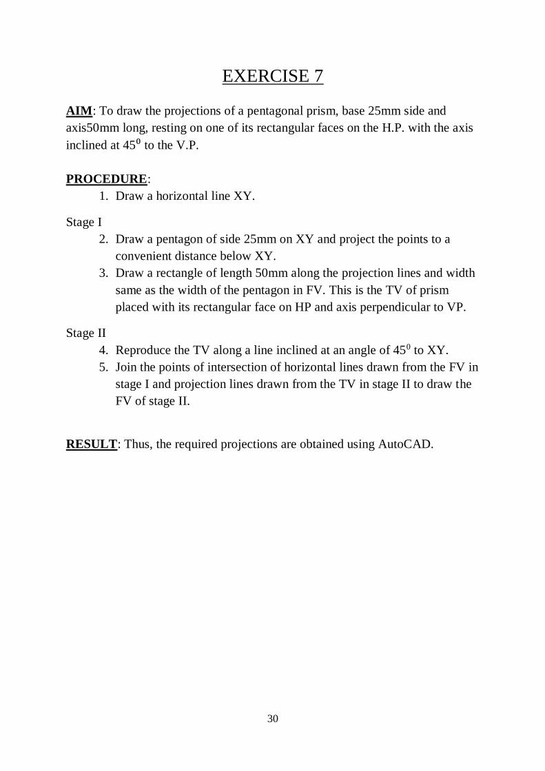
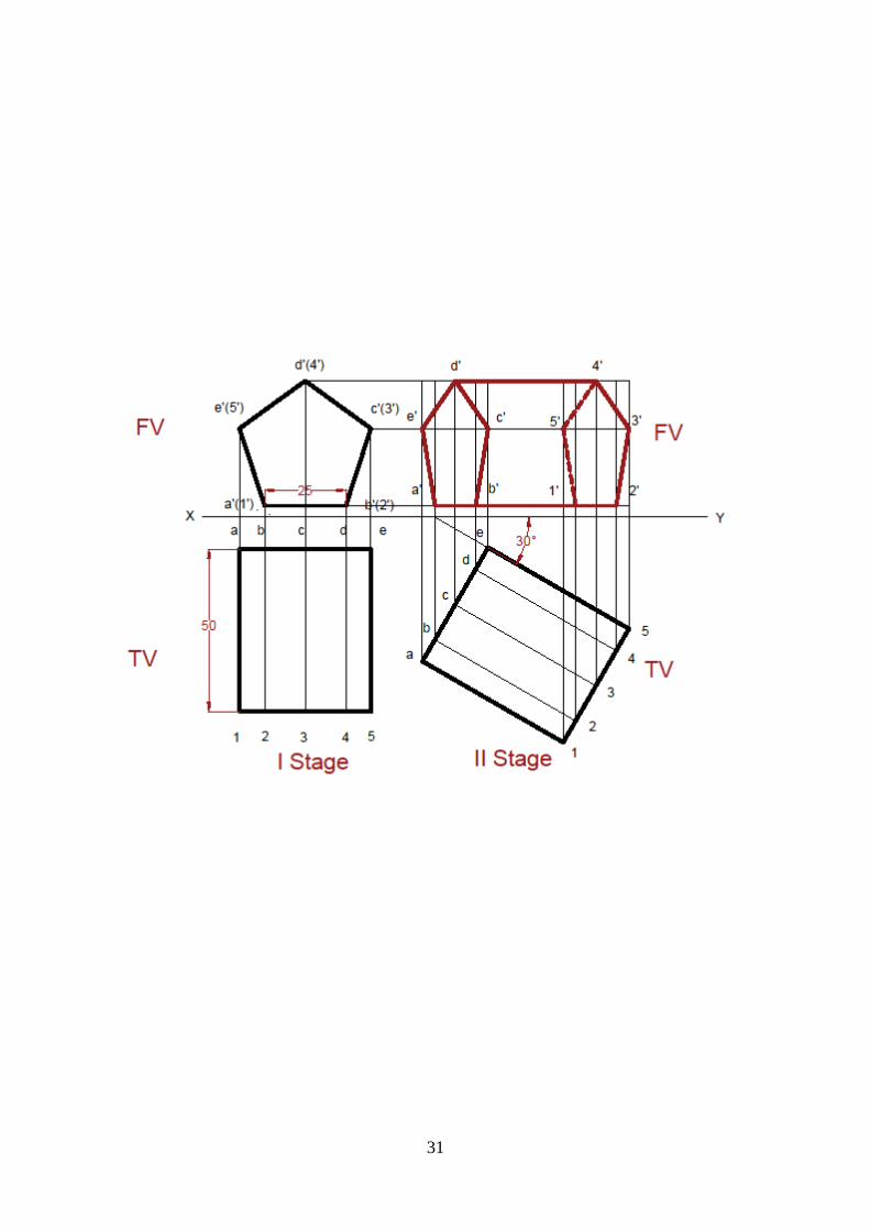
EXERCISE 7
AIM: To draw the projections of a pentagonal prism, base 25mm side and
axis50mm long, resting on one of its rectangular faces on the H.P. with the axis
inclined at 45⁰ to the V.P.
PROCEDURE:
1. Draw a horizontal line XY.
Stage I
2. Draw a pentagon of side 25mm on XY and project the points to a
convenient distance below XY.
3. Draw a rectangle of length 50mm along the projection lines and width
same as the width of the pentagon in FV. This is the TV of prism
placed with its rectangular face on HP and axis perpendicular to VP.
Stage II
4. Reproduce the TV along a line inclined at an angle of 450 to XY.
5. Join the points of intersection of horizontal lines drawn from the FV in
stage I and projection lines drawn from the TV in stage II to draw the
FV of stage II.
RESULT: Thus, the required projections are obtained using AutoCAD.
31
32
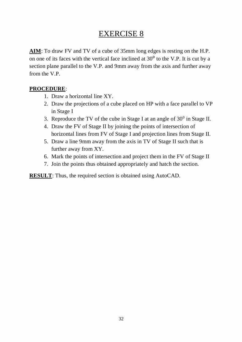
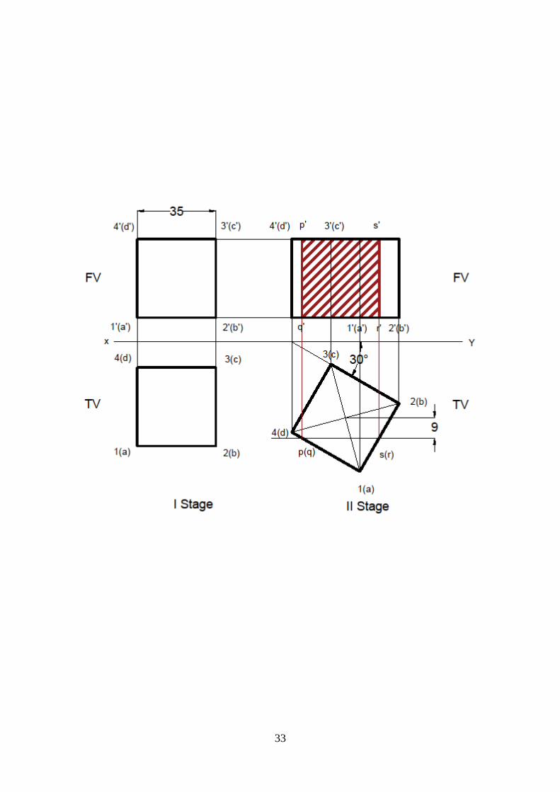
EXERCISE 8
AIM: To draw FV and TV of a cube of 35mm long edges is resting on the H.P.
on one of its faces with the vertical face inclined at 30⁰ to the V.P. It is cut by a
section plane parallel to the V.P. and 9mm away from the axis and further away
from the V.P.
PROCEDURE:
1. Draw a horizontal line XY.
2. Draw the projections of a cube placed on HP with a face parallel to VP
in Stage I
3. Reproduce the TV of the cube in Stage I at an angle of 300 in Stage II.
4. Draw the FV of Stage II by joining the points of intersection of
horizontal lines from FV of Stage I and projection lines from Stage II.
5. Draw a line 9mm away from the axis in TV of Stage II such that is
further away from XY.
6. Mark the points of intersection and project them in the FV of Stage II
7. Join the points thus obtained appropriately and hatch the section.
RESULT: Thus, the required section is obtained using AutoCAD.
33
34
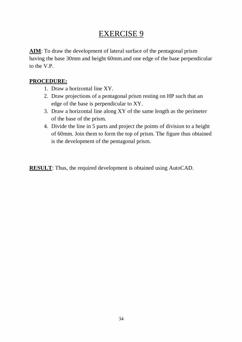
EXERCISE 9
AIM: To draw the development of lateral surface of the pentagonal prism
having the base 30mm and height 60mm.and one edge of the base perpendicular
to the V.P.
PROCEDURE:
1. Draw a horizontal line XY.
2. Draw projections of a pentagonal prism resting on HP such that an
edge of the base is perpendicular to XY.
3. Draw a horizontal line along XY of the same length as the perimeter
of the base of the prism.
4. Divide the line in 5 parts and project the points of division to a height
of 60mm. Join them to form the top of prism. The figure thus obtained
is the development of the pentagonal prism.
RESULT: Thus, the required development is obtained using AutoCAD.
35
36
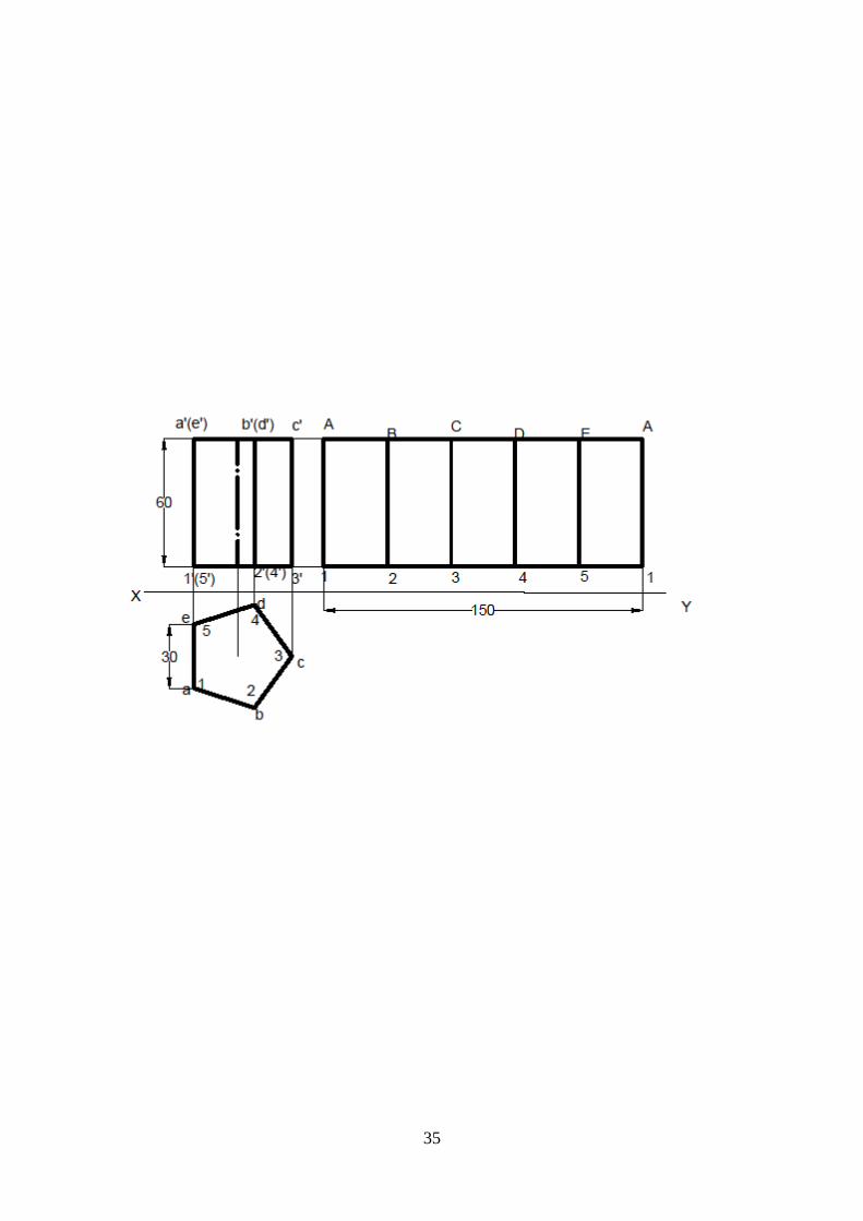
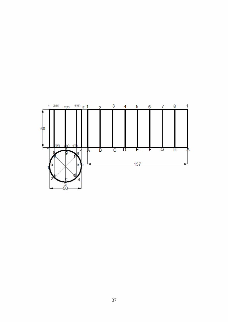
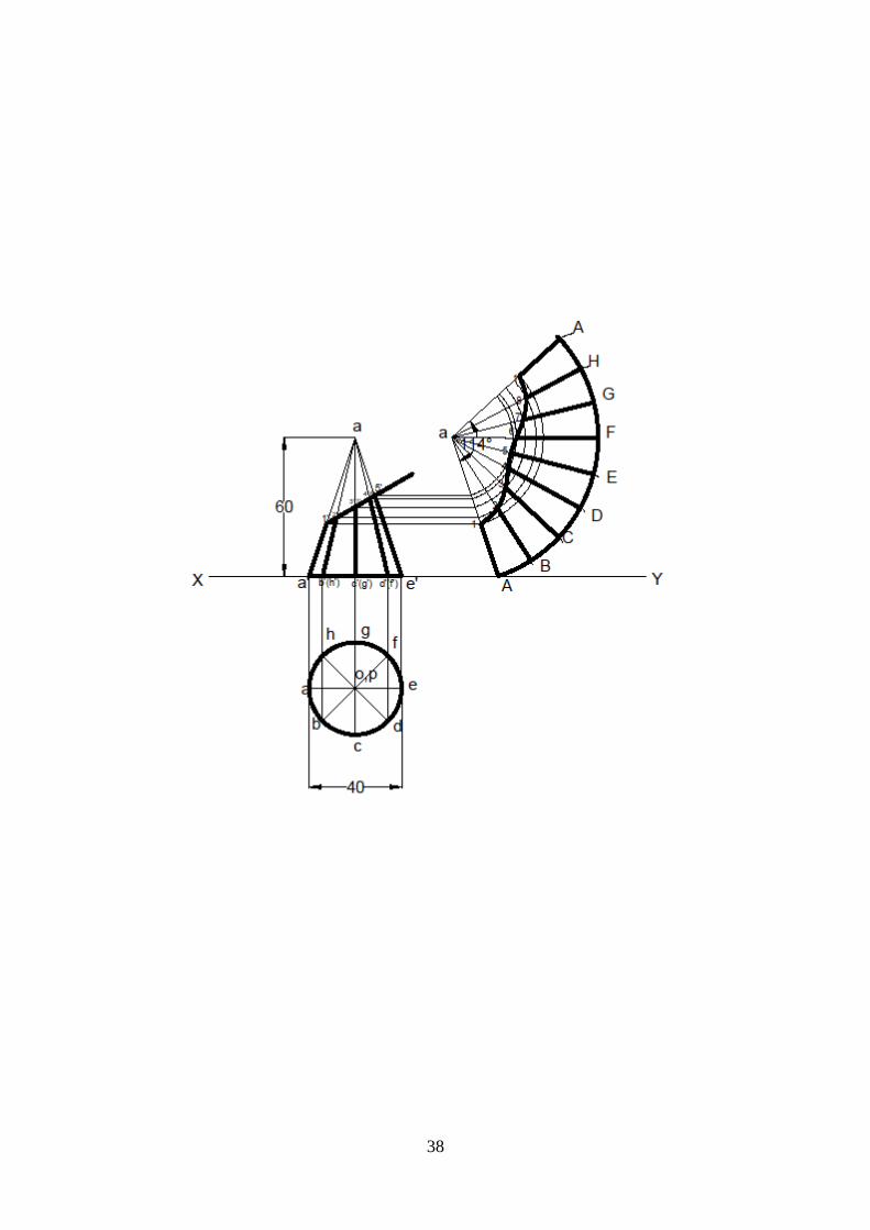
EXERCISE 10
AIM: To draw the development of lateral surface of
i. A cylinder having the base 50mm diameter and height 60mm.
ii. A cone having the base 40mm diameter and 60mm long axis is cut by
a section plane passing through the midpoint of the axis making an
angle of at 30⁰ with base.
PROCEDURE:
Case I
1. Draw a horizontal line XY.
2. Draw a circle of 50mm diameter in TV. Divide the circle into 8 parts
and project the points above XY to draw the FV of the cylinder.
3. Draw a line on XY of length same as the circumference of the base of
the cylinder and divide it into 8 parts.
4. Erect perpendiculars to a height of 60 mm from these points of
division to draw the top of the cylinder. The figure thus obtained is the
development of the cylinder.
Case II
1. Draw a horizontal line XY.
2. Draw a circle of 40mm diameter in TV. Divide the circle into 8 parts and
project the points to XY.
3. Mark the apex of the cone on the axis at a distance of 60mm from XY.
Join the points on XY to the apex to obtain the FV of the cone.
4. Measure ϴ= 𝑟
𝑙(2п) ; r= radius of the circle, l= Slant height of the cone
5. Draw a line equal to slant edge. With one end of the line as centre, draw
an arc subtending ϴ at the centre.
6. Divide the arc into 8 parts and join the points of division with the centre.
7. Draw a line through the midpoint of the axis in FV obtained in step 3,
making 300 with the base. Mark the points of intersection.
8. Mark these points on the line drawn in step 5 and draw arcs through
them.
9. Join the points suitably to obtain the development of the cut section.
RESULT: Thus, the required development is obtained using AutoCAD.
37
38

39
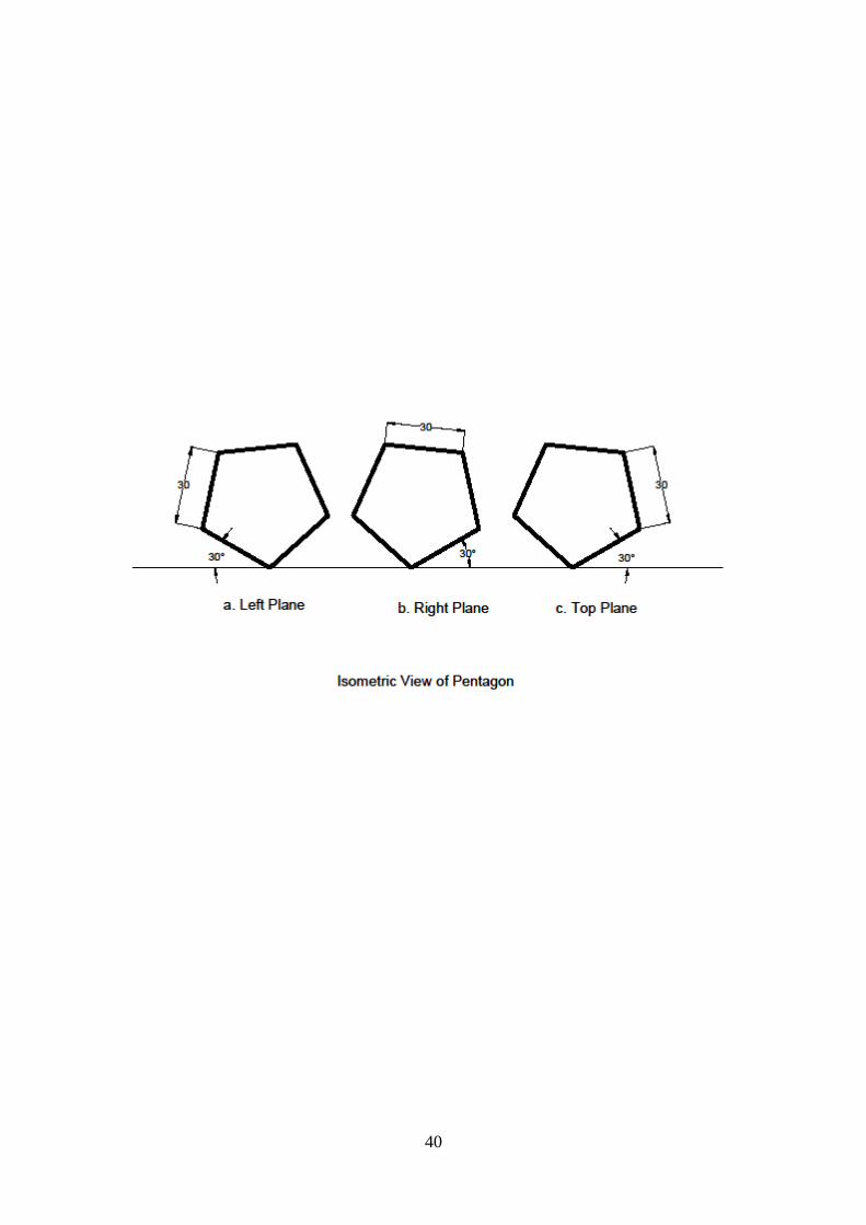
EXERCISE 11
AIM: Construct isometric view of regular pentagon of side 30mm.
PROCEDURE:
1. Draw a horizontal line for reference.
2. Switch to isometric snap.
3. Draw a pentagon with edge length 30mm in left plane. Take the base
along the axis making 1500 with the reference line.
4. Switch to right plane to draw the pentagon. Take the base along the
axis making 300 with the reference line.
5. Switch to top plane to draw the pentagon. The two axes are inclined at
300 and 1500 in top plane. Thus the pentagon drawn appears like a
pentagon drawn in left or right plane.
RESULT: Thus, the isometric views are obtained using AutoCAD.
40

41
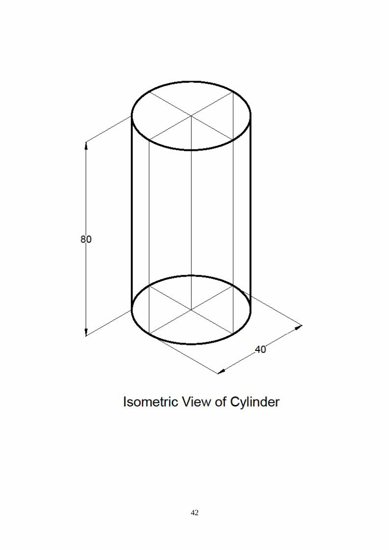
EXERCISE 12
AIM: Draw the cylinder of base 40mm diameter and height 80mm in isometric
view.
PROCEDURE:
1. Switch to isometric snap.
2. Draw an isocircle of diameter 40mm in isometric view. Use
Ellipse>Isocircle
3. Mark the centre of the circle. Erect the axis of length 80mm through
the centre.
4. Draw another isocircle at the end of the axis.
5. Extend lines through diametric ends of the base isocircle to the top
isocircle.
6. Draw lines parallel to the axis at the extremes of the isocircles drawn
to represent the end generators of the cylinder.
RESULT: Thus, the isometric view of the cylinder is obtained using AutoCAD.
42

43
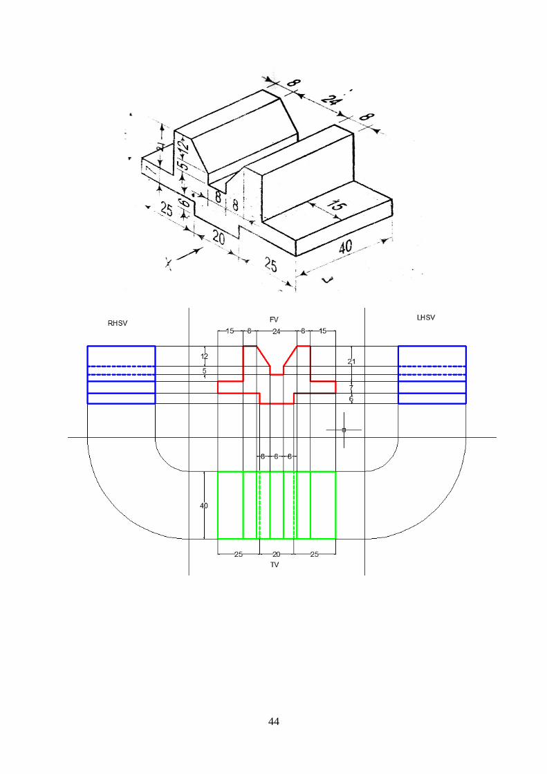
EXERCISE 13
AIM: Draw Orthographic projections for a given Isometric drawing.
PROCEDURE:
1. Type limits in command menu and set them to 297,210 for A4.
2. Change the units to millimeters from inches and also precision to 0 by
clicking Format > Units >Ok.
3. To view the page type zoom > enter and type a > enter in command
bar.
4. Draw a horizontal line for reference
5. Use toolbar options to draw the various views. Draw FV. Project to
draw TV. Use projections from FV, TV to draw LHSV, RHSV.
6. Edit the drawings by using edit commands.
7. Save the drawings.
8. Plot the completed views of drawing
RESULT:
The required Orthographic projections are drawn from given isometric
view by using AutoCAD software.
44
45
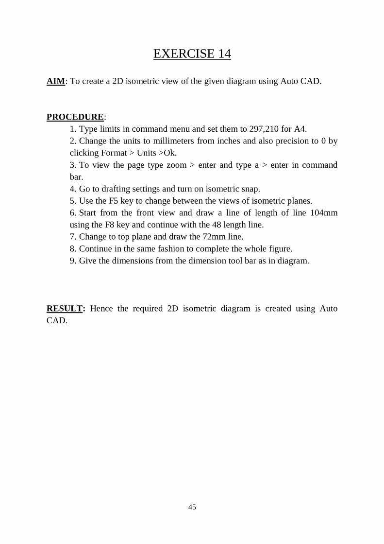
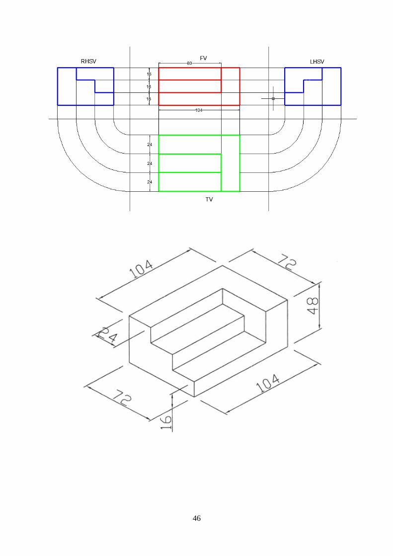
EXERCISE 14
AIM: To create a 2D isometric view of the given diagram using Auto CAD.
PROCEDURE:
1. Type limits in command menu and set them to 297,210 for A4.
2. Change the units to millimeters from inches and also precision to 0 by
clicking Format > Units >Ok.
3. To view the page type zoom > enter and type a > enter in command
bar.
4. Go to drafting settings and turn on isometric snap.
5. Use the F5 key to change between the views of isometric planes.
6. Start from the front view and draw a line of length of line 104mm
using the F8 key and continue with the 48 length line.
7. Change to top plane and draw the 72mm line.
8. Continue in the same fashion to complete the whole figure.
9. Give the dimensions from the dimension tool bar as in diagram.
RESULT: Hence the required 2D isometric diagram is created using Auto
CAD.
46