Embed Size (px)
Citation preview
Quik Build
Panels
User should check the
validity of the Certificate by contacting Member
Secretary, BMBA at
BMTPC or the Holder of
this Certificate.
Name and Address of Certificate Holder:
Beardsell Ltd. 47, Greams Road, Chennai 600 006 Tamilnadu
Performance Appraisal
Certificate No.
PAC No 1019-S/2015
Issue No. 01
Date of Issue: 24.04.2015
Building Materials & Technology Promotion Council Ministry of Housing & Urban Poverty Alleviation
Government of India
Core 5A, First Floor, India Habitat Centre,
Lodhi Road, New Delhi – 110 003 Tel: +91-11-2463 8096, 2463 8097; Fax: +91-11-2464 2849
E-mail: [email protected] Web Site: http://www.bmtpc.org

2
CONTENTS PART 1 CERTIFICATION…………………………………………………………………… 3
1.1 Certificate Holder ………………………………………………………………………… 3
1.2 Description of System …………………………………………………………………… 3
1.3 Assessment …………………………………………………………………………….... 4
1.4 Uses of the System ……………………. ………………………………………………. 4
1.5 Conditions of Certification ………………………………………………………………. 5
1.6 Certification ………………………………………………………………………………. 5
PART 2 CERTIFICATE HOLDER’S TECHNICAL SPECIFICATION ………………..... 5
2.1 General …………….…………………………………………………………………...... 5
2.2 Specifications for the System …………………………….......................................... 6
2.3 Design Considerations ………………………………………………………………….. 7
2.4 Manufacturing Process …………………………………………………………………. 8
2.5 Inspection & testing ……………………………………………………………………… 9
2.6 Handling, Storage & Identifying the Components ……………………………………. 9
2.7 Selection & Installation ………………………………………………………………….. 9
2.8 Construction System ……………………………………………………………………. 9
2.9 Health & Safety…………………………………………………………………………… 13
2.10 Choosing Size & Thickness.................................................................................. 13
2.11 Maintenance Requirements …………………………………………………………... 13
2.12 Skilled/Training Needed for Installation ……………………………………………… 13
2.13 Guarantees/ Warranties Provided by the PAC Holder …………………………….. 13
2.14 Services Provided by the PAC Holder to the Customer…………………………….
2.15 Manuals…………………………………………………………………………………..
14 14
2.16 Responsibility …………………………………………………………………………… 14
PART 3 BASIS OF ASSESSMENT AND BRIEF DESCRIPTION OF ASSESSMENT PROCEDURE …………………………………………………………………………………
14
3.1 Assessment ………………………………………………………………….................. 14
3.2 Tests Performed ………………………………………………………………………… 14
3.3 Usage of the System ……………………………………………………………………. 17
PART 4 STANDARD CONDITIONS ………………………………………………............ 18
PART 5 LIST OF STANDARDS AND CODES USED IN ASSESSMENT…………….. 20
CERTIFICATION …………………………………………………………………..... 21
PART 6 ABBREVIATIONS ………………………………………………………… 22
PERFORMANCE APPRAISAL CERTIFICATION SCHEME – A BRIEF……... 23
ANNEX I Quality Assurance Plan………………………………………………… 24
ANNEX II Process Flow Chart………...…………………………………………… 25 ANNEX III Construction Drawings………………………………………………… 26
3
PART 1 CERTIFICATION
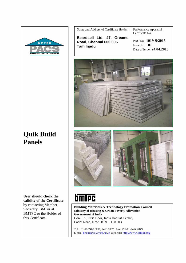
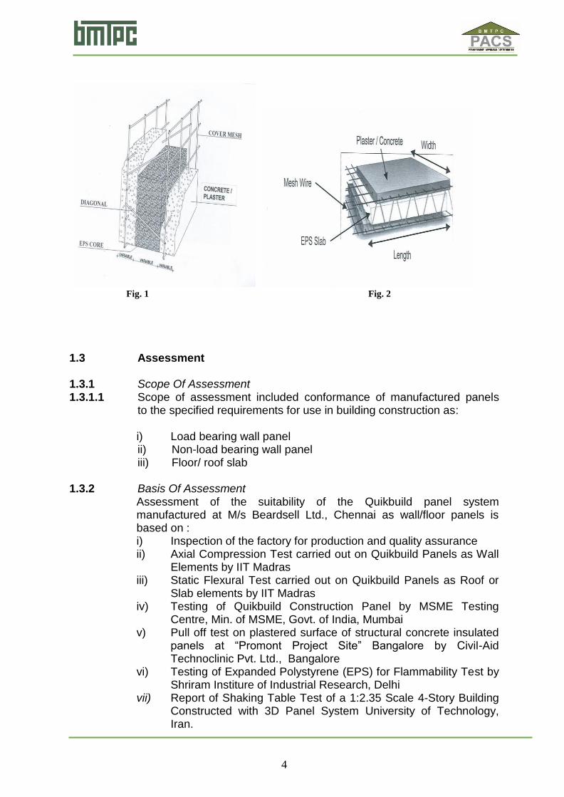
1.1 Certificate Holder: Beardsell Ltd. 47, Greams Road, Chennai 600 006 Tel: 044-28293296 e-mail: [email protected] 1.2 Description Of System 1.2.1 Name of the System – QuikBuild Panels 1.2.2 Brief Description – QuikBuild panel system consists of a welded wire
space frame integrated with a polystyrene insulation core. The wall panel is placed in position and a wythe of concrete is applied to both sides. The wall panel receives its strength and rigidity from the diagonal cross wires welded to the welded-wire fabric on each side. This combination produces a truss behavior, which provides rigidity and shear terms for a full composite behavior.
Steel trusses are pierced through the polystyrene core and welded to the outer layer sheets of galvanized steel mesh to form a rigid panel. The shell of the structure is built by manually erecting the panels directly onto the slab with reinforcement rods. Desired utilities like doors, windows and ventilators may be pre-built while plumbing, electrical conduits may be added onsite.
The wall is then finished by plastering with cement using the traditional method or by shotcreting machine to create a monolithic structure.
These panels are used in the construction of exterior and interior load-bearing and non-load bearing walls and floors of buildings of all types of construction.
Description of the Panel is shown in Fig. 1 & 2
4
Fig. 1 Fig. 2 1.3 Assessment 1.3.1 Scope Of Assessment 1.3.1.1 Scope of assessment included conformance of manufactured panels
to the specified requirements for use in building construction as:
i) Load bearing wall panel ii) Non-load bearing wall panel iii) Floor/ roof slab
1.3.2 Basis Of Assessment
Assessment of the suitability of the Quikbuild panel system manufactured at M/s Beardsell Ltd., Chennai as wall/floor panels is based on : i) Inspection of the factory for production and quality assurance ii) Axial Compression Test carried out on Quikbuild Panels as Wall
Elements by IIT Madras iii) Static Flexural Test carried out on Quikbuild Panels as Roof or
Slab elements by IIT Madras iv) Testing of Quikbuild Construction Panel by MSME Testing
Centre, Min. of MSME, Govt. of India, Mumbai v) Pull off test on plastered surface of structural concrete insulated
panels at “Promont Project Site” Bangalore by Civil-Aid Technoclinic Pvt. Ltd., Bangalore
vi) Testing of Expanded Polystyrene (EPS) for Flammability Test by Shriram Institure of Industrial Research, Delhi
vii) Report of Shaking Table Test of a 1:2.35 Scale 4-Story Building Constructed with 3D Panel System University of Technology, Iran.
5
1.4 Use Of The Quickbuild Panels 1.4.1 The panels shall be used in the construction of exterior and interior load-bearing and non-load bearing walls and floors of buildings of all types of construction.
1.4.2 Durability The Certificate Holder shall provide necessary structural warranty ensuring durability of the system to the user, on demand 1.5 Conditions Of Certifications 1.5.1 Technical Conditions (i) Raw materials and the finished panels shall conform to the requirements of the prescribed specifications.
(ii) The building to be constructed using 3D panel system shall be in accordance with the specifications, manufacturing & construction process prescribed by the manufacturer and designed by competent structural Engineers.
(iii) The production capability and quality of the panels vis-à-vis requirements specified need to be verified for each plant/ establishment engaged in the production and execution of the system.
(iv) Buildings to be constructed with the 3D panel system should be constructed only with technical support or supervision by qualified engineers and builders, based on structural designs and Seismic evaluation & Wind forces carried out to comply with prevailing standards; this is applicable even for low-rise and affordable mass housing to provide safety of structures.
(v) It is strongly recommended that structural engineers and building designers associated with such type of construction should thoroughly get familiar with the various structural aspects of the system. It is also recommended that Architects and Construction Engineers who undertake such building design `and construction gain familiarity with the properties and materials, characteristics of 3D panel system and its applications.
(vi) Beardsell shall give evidence/analysis report from recognized institutions of the performance of G+3 or higher structure against earthquake forces as per IS 1893(Part 1):2002 before undertaking projects using load bearing wall panels for structure G+3 or more.
(vii) The Certificate holder shall inform BMTPC as and when any new plant is set up in India.
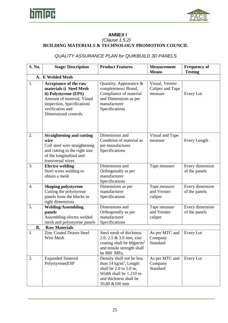
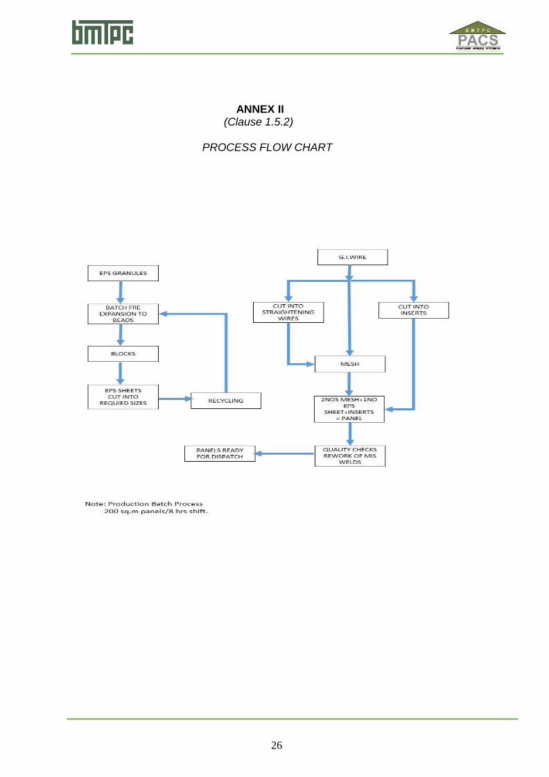
1.5.2 Quality Assurance The Certificate Holder shall implement & maintain a Quality Assurance System in accordance with Scheme of Quality Assurance (SQA) given in Annex I attached with this Certificate. Process Flow Chart (Standard Operating Procedure) for 3D panel is also given in Annex II.

6
1.5.3 Handling of User Complaints 1.5.3.1 The Certificate holder shall provide quick redressal to consumer/user
complaints proved reasonable & genuine and within the conditions of warranty provided by it to customer/purchaser.
1.5.3.2 The Certificate holder shall implement the procedure included in the
SQA. As part of PACS Certification he shall maintain data on such complaints with a view to assess the complaint satisfaction and suitable preventive measures taken.
1.6 Certification 1.6.1 On the basis of assessment given in Part 3 of this Certificate & subject
to the conditions of certification, use & limitations set out in this Certificate and if selected, installed & maintained as set out in Parts 1 & 2 of this Certificate, the panels covered by this Certificate are fit for use set out in the Scope of Assessment.
PART 2 CERTIFICATE HOLDER’S TECHNICAL SPECIFICATIONS
2.1 General 2.1.1 The PAC holder shall manufacture the panels in accordance with the
requirements specified in the PAC. In addition it shall follow the Company standards specifying requirements of various materials used in the manufacture of these sections (see Part 5)
2.2 Specifications For The System The PAC holder shall strictly comply with the requirements of the
specifications of materials mentioned in PAC. The 3D Panels shall be manufactured in
accordance with the requirements specified. 2.2.1 Technical Specifications 2.2.1.1 Raw Materials
1. Zinc Coated Cold Drawn Steel Wire – Shall be of 2.5mm dia and
zinc coating galvanizing shall be of 60 gm/m2 ± 5 gm/m2 1.1 Mechanical characteristics
Yield stress : > 600 N/mm2 Breaking load : > 680 N/mm2 Elongation : > 8%
1.2 Chemical characteristics -- Weldability % C : < 0.24 % P : < 0.055 % S : < 0.055 % Ceq : < 0.52
2. Expanded Sintered Polystyrene – Self-extinguishing type EPS 80 in accordance with UNI EN 13163:2013 (IS 4671: 1984) having density not less than 15 kg/m3
7
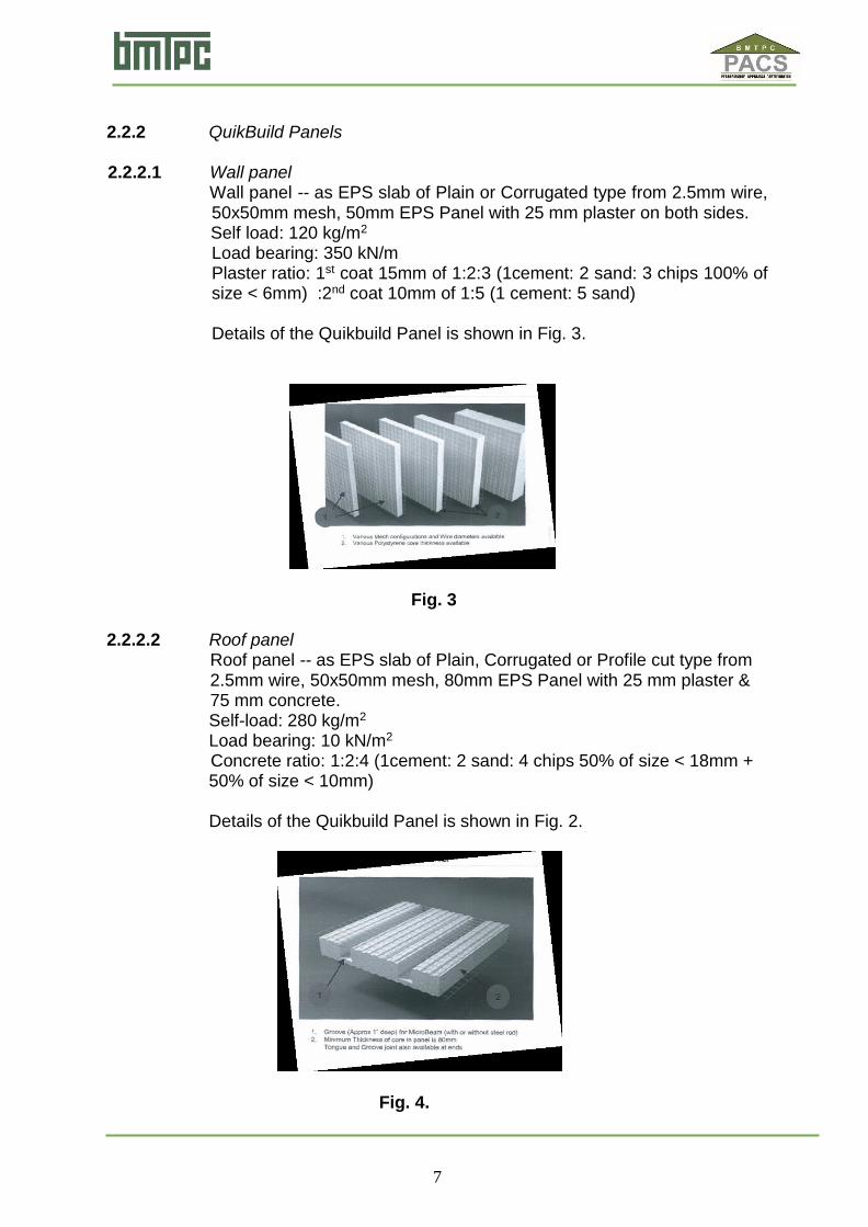
2.2.2 QuikBuild Panels
1. 1.2.1. 2.2.2.1 Wall panel 2. Wall panel -- as EPS slab of Plain or Corrugated type from 2.5mm wire,
50x50mm mesh, 50mm EPS Panel with 25 mm plaster on both sides. 3. Self-l Self load: 120 kg/m2
Load bearing: 350 kN/m Plaster ratio: 1st coat 15mm of 1:2:3 (1cement: 2 sand: 3 chips 100% of size < 6mm) :2nd coat 10mm of 1:5 (1 cement: 5 sand) Details of the Quikbuild Panel is shown in Fig. 3.
Fig. 3
4. p 2.2.2.2 Roof panel
Roof panel -- as EPS slab of Plain, Corrugated or Profile cut type from 2.5mm wire, 50x50mm mesh, 80mm EPS Panel with 25 mm plaster & 75 mm concrete.
Self-load: 280 kg/m2 Load bearing: 10 kN/m2 Concrete ratio: 1:2:4 (1cement: 2 sand: 4 chips 50% of size < 18mm + 50% of size < 10mm) Details of the Quikbuild Panel is shown in Fig. 2.
Fig. 4.
8
2.2.2.3 Staircase Panel For Staircase, a wall panel is used as slab and EPS pieces in triangular forms are placed like steps and fixed with welded wire mesh.
2.3 Design Consideration/ Procedure 2.3.1 General
i) The QUikBuild 3 D panels may be designed using the appropriate design software. The system may be used as an alternate solution to a building designed using conventional brickwork masonry wall and RCC roofing. ii) The system is intended for use where Architectural drawings are available and satisfy the various requirements. The Architect and Engineer designer team of the concerned developer (client) is responsible for the drawings and overall building design to comply with the various regulatory requirements applicable to the area. iii) Structural design for any project shall be done by the structural engineer trained by Beardsell. M/s Beardsell engineer shall also liase with the engineer for the developer and provide the necessary loading information for the design of the foundation. iv)The system shall be designed to provide the required performance against the loads to be taken into account in accordance with IS 875 (Parts 1-5):1987 and the data given by Beardsell for various panels. It shall also provide the required bearing resistance for earthquake and wind forces as per IS 875 (Part 3):1987 and IS 1893 (Part 1):2002, wherever applicable. The details of design shall be made available by Beardsell on demand for vetting, if required. v) Foundation shall be specifically designed in accordance with provision given in IS 1904:1986. Both single and double panels should have starter bars from either foundation or ground floor slab. All foundations should be designed by experienced engineer with appropriate reference. vi) The design assumptions, detailed calculations, references to necessary and detailed design drawings shall be made available on demand, if required. The structural design calculations should clearly demonstrate structural integrity and stability including connection details. Design calculations should have proper sketches annotated in English. vii) In addition, any other requirement regarding safety against earthquake need to be ensured by the designer as per prevailing codal requirements.
2.3.2 Structure
The QUikBuild 3 D panel receives its outer plane strength and rigidity by truss action where the shotcrete layers are the chord members. The design of QUikBuild 3 D panel shall follow the requirement of relevant Indian Standards wherever applicable. Design guidelines and requirements set out in the Technical literature provided by Beardsell shall be followed.
9
2.3.3 Wind Uplift The design of roof to wall connections shall be to a specific design to ensure that the roof structure is properly restrained against uplift.
2.3.4 In-fill Wall
When used as in-fill wall in framed RCC structure, the structure shall be designed in accordance with IS 456:2000. The fixing of the panels shall be done in accordance with the details provided by Beardsell (See Figs.7 to 11)
2.3.5 Water Tightness Externally the walls shall be protected by an approved render applied to
35 mm sprayed 25 MPa concrete. DPC/radar barrier shall be installed at ground level to prevent rising damp. DPC shall also be used around window sills and a sealant shall be applied around window or door frames.
2.3.6 Durability IS 456:2000 specifies exposure conditions, concrete strength and cover requirements. As EMMEDUE Advanced Building System may be used in different parts of the country, different situations may arise. Exterior coating may be applied to provide additional protection to the reinforcement against corrosion in aggressive environment.
2.4 Manufacturing process QuikBuild 3D panel is manufactured from welded wire space frame
integrated with a polystyrene (EPS) insulation core sandwiched between two layers of engineered galvanized steel mesh that are held together with steel trusses. Steel trusses are pierced through the polystyrene core and welded to the outer layer sheets of galvanized steel mesh to form a rigid panel. The shell of the structure is built by manually erecting the panels directly onto the slab with reinforcement rods. Panels shall be machine manufactured using specified quality of raw materials to get the desired configuration and following proper Quality Assurance System.
2.5 Inspections & Testing Inspections & testing shall be done at appropriate stages of
manufacturing process. The inspected panels shall be stored & packed to ensure that no
damage occurs during transportation. As part of quality assurance, regular in-process inspections shall be carried out by the trained personnel of the PAC holder.
2.6 Handling , Storage and Identifying the Components
The panels should be stored on a clean, flat hard surface area on the site. The panels should not be laid down directly on the ground to prevent them from getting dirty, which could lead to problems of plaster adhesion. Preferably, panels should be stored on timber battens

10
approx. 2m apart. The panels should not be exposed to sunlight for not more than 1 month either in storage or during construction in order to prevent changing the polystyrene appearance. The panels should be bound carefully to make sure these are not accidentally blown by the wind. Long term storage of the panels shall be done in a covered, protected, dry environment so that corrosion of the reinforcement does not occur and the panels do not get damaged. Panels shall be stored and transported to site in a manner that prevents damage, buckling or sprawling of the polystyrene or bending of the mesh reinforcement. Operatives should place the panels in position and tie them down to starter bars of adjoining panels and slabs in the manner described in the Operational Manual. Panels should be properly braced to provide rigid temporary support to the walls during erection and concrete spraying and placing of concrete in slabs. Propping of walls and slabs should be in accordance with the Operational Manual. The panels shall be delivered to the site with an identification issued by the manufacturer that reports the element height. The panel layout shall provide instructions for laying the components correctly.
2.7 Selection & Installation The QuickBuild 3D panels shall be installed by trained persons with an
understanding of the system, in accordance with the technical literature and the PAC.
2.8 Construction System 2.8.1 The QuikBuild construction system uses modular panels to build a
frame for a structure. Concrete or plaster is used in conjunction with these panels to form the structure.
The panel consists of (1) a polystyrene core sandwiched between two engineered layers of (2) Galvanized steel mesh. In addition a (3) Galvanized steel truss is pierced through the Polystyrene core
welded to each of the outer layer sheets of steel mesh. Details of QuikBuild Modular Panel is shown in Fig.5.
Fig. 4 Fig. 5
11
2.8.2 The method of construction using QuikBuild panel shall be as follows: 2.8.2.1 Foundation: (i) Marking, levelling, excavation for plinth and filling with layers of sand
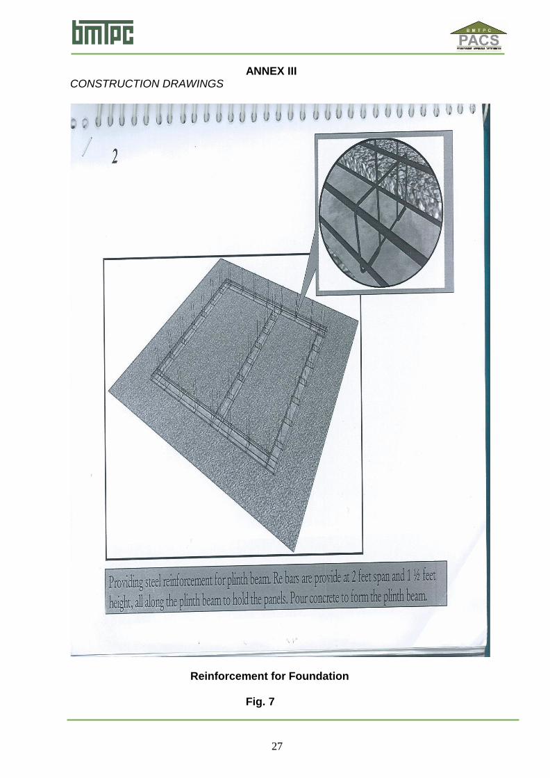
and PCC shall be carried out. (ii) Steel reinforcement shall be provided for plinth beam. Reinforcing
bars shall be provided 600mm c/c & 450mm c/c height, all along the plinth beam to hold the panels. Concrete shall be poured to form the plinth beam. (See Fig. 7)
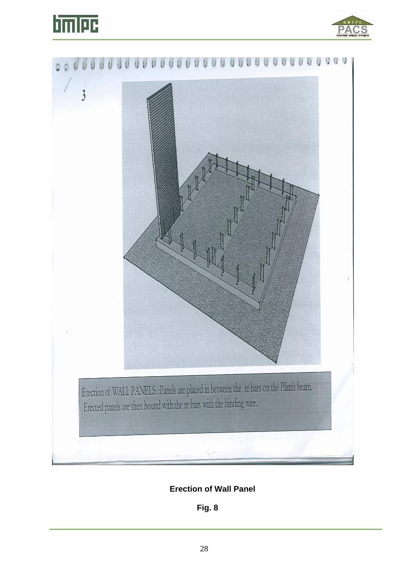
2.8.2.2 Erection of wall panels: (i) Panels shall be placed in between the reinforcing bars on the plinth
beam. Erected panels shall then be bounded with reinforcing bars with the binding wire. (See Figs. 8 & 9)
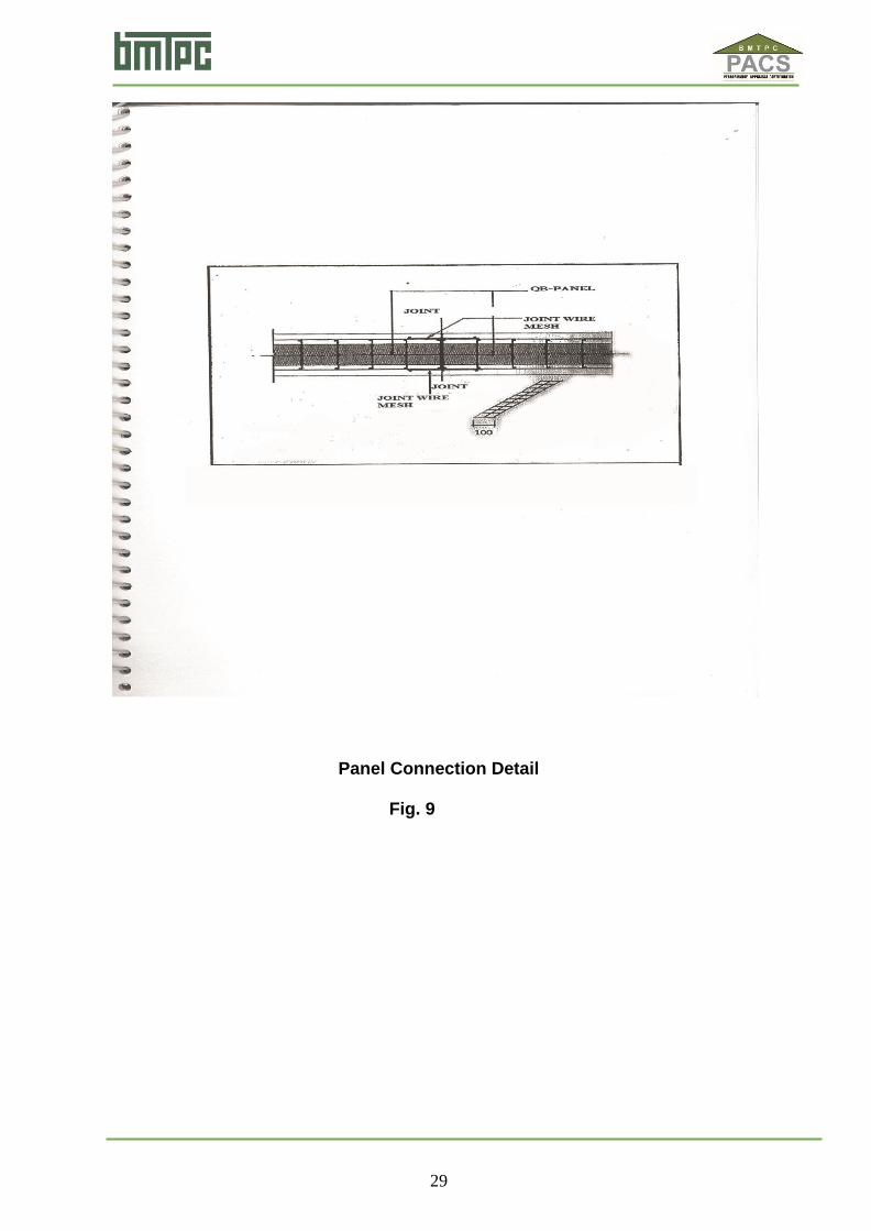
2.8.2.3 Wall panel joints: (i) Panel to panel shall be joined with a joining mesh, I mesh is used for
a flat joint. I mesh is overlapped over the two panels and shall be bounded with a binding wire or stapled using a clinching tool. The joining mesh shall be bounded to the panels at every 100 mm spacing. (See Fig.10)
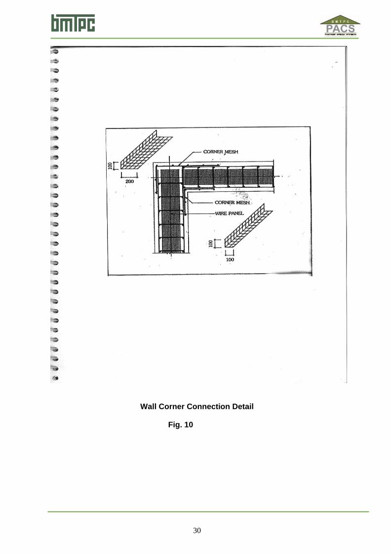
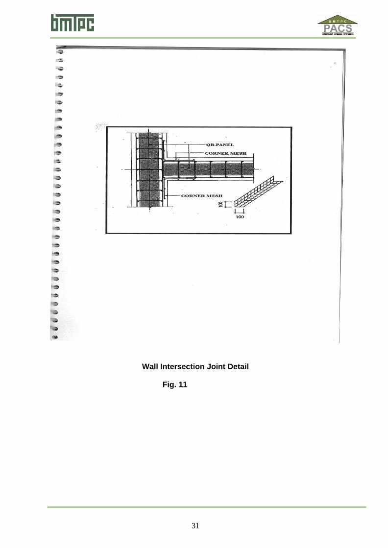
(ii) Panels at the corners shall be joined with a L mesh or corner joining mesh. The mesh shall be placed over the joint at the corner and shall be bounded with a binding wire to the panels. All corners of the building. At corners of the building, the panels shall be joined from both inside and outside with L mesh. Binding shall be done either by a binding wire or stapled using a clinching tool. (See Figs. 10 to 13 & 16)
2.8.2.4 Wall Panel erection: Erection of all wall panels shall then be completed leaving space for the
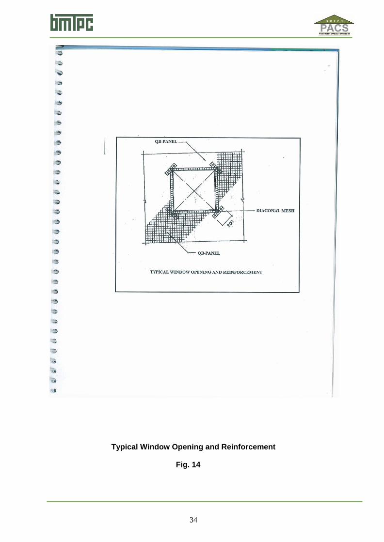
doors. (See Fig. 15) 2.8.2.5 Door & Window cutouts: Opening for windows shall be cut with the help of a cutter. Door &
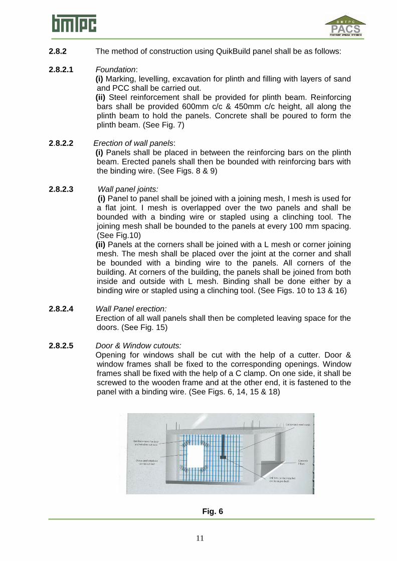
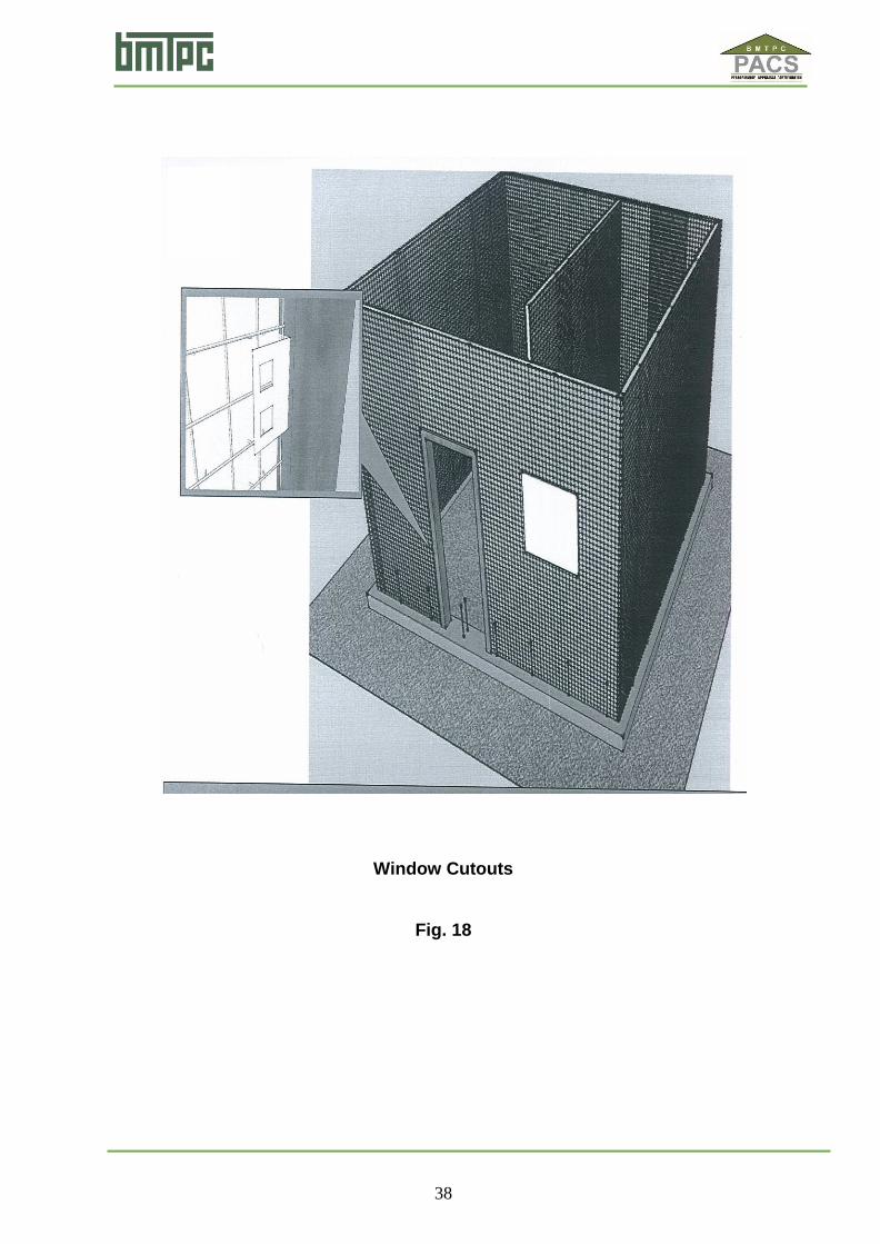
window frames shall be fixed to the corresponding openings. Window frames shall be fixed with the help of a C clamp. On one side, it shall be screwed to the wooden frame and at the other end, it is fastened to the panel with a binding wire. (See Figs. 6, 14, 15 & 18)
Fig. 6
12
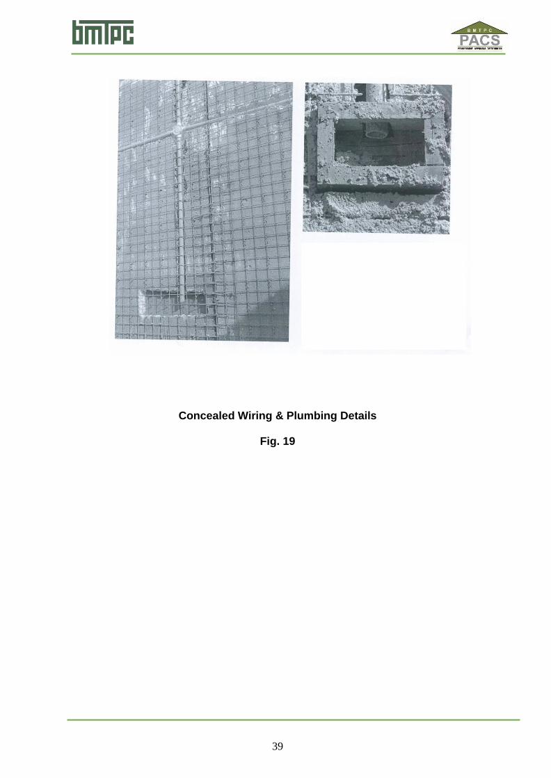
2.8.2.6 Concealed Wiring and Plumbing: For concealed wiring grooves shall be made in the EPS using a hot air
gun and necessary PVC pipes are inserted into the grooves. Switch boxes shall be fixed by cutting of the mesh where boxes are to be fixed.
Services The laying of pipes for plumbing, electrical installation, heating services
etc. takes place after the panels have been erected and before spraying of concrete takes place. Services may be concealed within the panels by installing them behind the welded wire fabric. The chases in the polystyrene are carried out by a hot-air gun or similar tools. If insufficient space exists between the welded-wire fabric and polystyrene, the polystyrene may be cut away sufficiently to form the chase for the services. The area surrounding the cut should be restored by the addition of extra mesh connected to the meshwork of the panel. Copper pipes, if used, should be insulated from the meshwork with felt PVC or similar protection. No props greater than 50 mm dia. should be insulated in the polystyrene. Service pipes or ducts 100 mm in diameter or more should be placed outside the structure or in ducts within the building. The location of services should be as per the service drawing for the structure. Any alteration or change should be addressed to Beardsell Ltd. and noted in the service drawings. PVC sheet and electric cables shall not come in contact with EPS and shall, therefore be contained within a conduit or be laid without conduits away from EPS. Where services penetrate the external panels, the penetration shall be made watertight on the outside. Clearances for service movement shall be made in accordance with the service element providers’ specifications. (See Figs. 19 & 24)
2.8.2.7 Plastering: Plaster both sides of the wall panels in two coats with first coat of 15mm
of mix 1:2:3 (1cement: 2 sand: 3 chips 100% of size < 6mm) and second coat of 10mm of mix 1:5 (1 cement: 5 sand. (See Fig. 20)
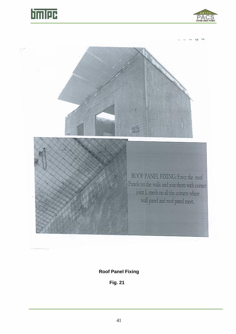
2.8.2.8 Roof panel fixing: Roof panels on the walls shall be erected and joined with corner joint L
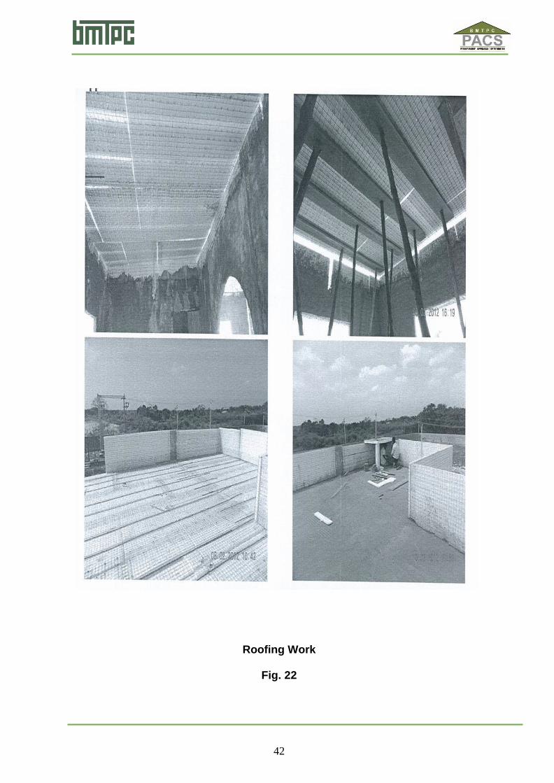
mesh on all the corners where wall and roof panels meet. (See Fig. 21) 2.8.2.9 Roofing work: (i) All roof panels shall be fixed and all wall and roof panels shall be
joined. (ii) Supports shall be placed to the roof panels. (iii) All parapet wall panels shall be fixed and bind it with the roof panel. (iv) Concrete shall be laid on the roof upto a thickness of 50 to 75m and
shall be allowed to cure for a period of 15 days.(See Fig. 22) 2.8.2.10 Finishing:
Building shall be finished with fine plastering. All other fixtures and

13
fittings shall be done as in the conventional type of building. After joinery installation has been completed using the details set out in the Technical literature, the interior and exterior finishes may be applied to the concrete surfaces. Interior surfaces (walls and ceiling) may be finished with a thin coat interior plaster applied in accordance with the Technical literature. Alternatively, any other suitable lining system may be applied. (See Fig. 23)
2.8.2.11 Concrete installation All concreting work shall be done in accordance with IS 456:2000 with
regard to workmanship and materials. Concrete is sprayed on the walls and ceiling using shotcrete pumps and is pumped in place for floor topping slabs. Upper level floor toppings slabs are usually placed before internal walls and ceilings to upper levels and allowed to cure to give a platform for spraying the interior. For shotcreting, guidance may be taken from IS 9012:1978. Some supports under slabs may be removed after 3 days but critical supports such as those at mid-span shall be left in place until the slab is fully cured. The structural engineering design shall provide the appropriate details for supports and sequence and timing of removal. Concrete shall be of correct strength and mix design as required by the structural engineering design. Generally, concrete shall be applied in two layers. The first layer shall be applied to a thickness to cover the welded-wire fabric and the second layer to give the final required thickness. The first layer shall usually be left to cure for a few days to provide initial load transfer to the panels. Any supports or stiffeners that have been attached to the panels shall be removed before the second layer is sprayed and the gaps left by the supports are in-filled with sprayed concrete. The first layer of concrete shall be left rough so as to give adequate key to second layer. Correct concrete thickness shall be measured as work proceeds. Screed points of concrete shall be used as gauges to give correct thickness and lines. Hand trowel finishing of the second layer shall be required to give the appropriate finish and surface tolerances. The ability to provide concrete finishes to the tolerances required by the designer is dependent on the skill and workmanship of the concrete finishes. Curing of concrete shall be carried out as set out in IS 456:2000; and required a minimum of 7 days for external concrete and 3 days for internal concrete. The concrete may be kept damp by applying water to the surfaces. This may also be carried out by means of fine spray hose or wet screens placed over the surface.
2.8.2.12 Precautions • Do not overload partition walls on one side only. Instead, spray the concrete on both sides alternatively.
• If the panel is cut during erection and its meshwork has no wire- crossing points, panels should be joined with flat meshwork (min. width 225 mm)
14
2.8.2.13 Fixing object to walls Light weight object: 2.5 mm screws, pins or similar devices may be used. Heavy object (shelves, water tanks etc.): Plastic pins with 45 mm screws or similar devices are recommended. Very heavy object: During erection, metal pins may be inserted in plaster pallets. Alternatively, threaded pins fastened with epoxy resin may be used.
2.9 Health and Safety
The Quikbuild 3 D Panel Technical literature shall be consulted for guidance for health and safety requirements such as personal protective clothing, protective glasses etc.
2.10 Choosing size and thickness Appropriate size and thickness of the panels shall be chosen to suit the structural, fire, acoustic and thermal requirements of the structure.
2.11 Maintenance Requirements A proper maintenance guide shall be given by the PAC holder to the
client. When building is to be repainted with fresh coat of paint after scraping existing paint, check for joint sealant, pipe joint, sun shade
etc. and carry out required maintenance and apply primer before paint is applied.
2.12 Skilled /Training Needed For Installation Workers shall be trained/ oriented on handling of panel and its erection,
support system, clamping system, infilling of reinforcement and concrete etc. with all required safety measures taken including heavy hats, protective shoes etc. PAC holder shall arrange training of workers, as required in this regard.
2.13 Guarantees/Warranties Provided By The PAC Holder PAC holder shall provide necessary guarantees/ warranties. A brochure
giving relevant details and warrantee detail shall be made available to the client.
I 2.14 Services Provided By The PAC Holder To The Customer
In-house testing of panels at regular intervals as per the Quality Control Assurance requirement shall be ensured by PAC Holder.
2.15 Manuals A site Installation & Erection Manual and a Manual for Health & Safety
shall be provided for each project incorporating the QuikBuild 3D Panel. 2.16 Responsibility
Specific design using QuikBuild 3D Panel is the responsibility of the designer with the instructions, supervision and guidance of Beardsell Ltd.
Quality of installation of the system on site is the responsibility of the trade persons engaged by the agency
15
3.1 Assessment
3.1.1 Factory Inspections The factory at Chennai was inspected by the technical team of the Council. The raw materials and finished products were found to be as per specifications. The firm has got necessary manufacturing and test facilities to produce the required components as per design and specifications. It operates a Quality Assurance system in the factory to ensure that the product conforms to the specified requirements.
3.2 Tests Performed 3.2.1 By IIT Madras
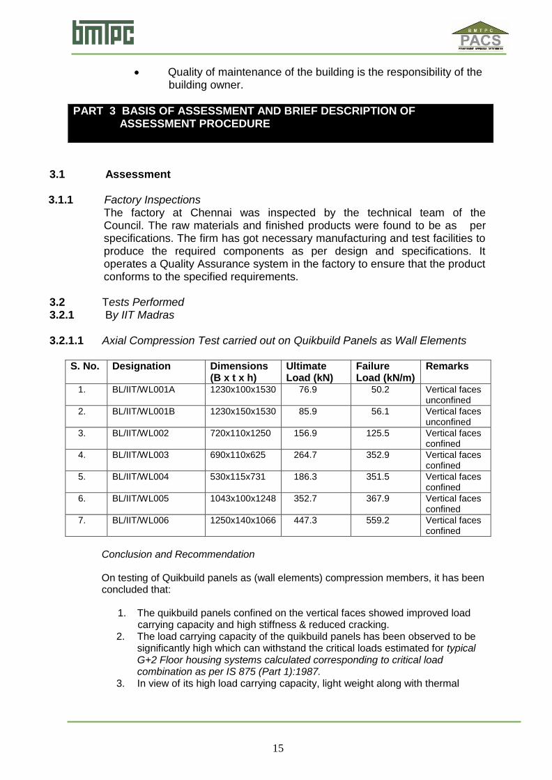
3.2.1.1 Axial Compression Test carried out on Quikbuild Panels as Wall Elements
S. No. Designation Dimensions (B x t x h)
Ultimate Load (kN)
Failure Load (kN/m)
Remarks
1. BL/IIT/WL001A 1230x100x1530 76.9 50.2 Vertical faces unconfined
2. BL/IIT/WL001B 1230x150x1530 85.9 56.1 Vertical faces unconfined
3. BL/IIT/WL002 720x110x1250 156.9 125.5 Vertical faces confined
4. BL/IIT/WL003 690x110x625 264.7 352.9 Vertical faces confined
5. BL/IIT/WL004 530x115x731 186.3 351.5 Vertical faces confined
6. BL/IIT/WL005 1043x100x1248 352.7 367.9 Vertical faces confined
7. BL/IIT/WL006 1250x140x1066 447.3 559.2 Vertical faces confined
Conclusion and Recommendation On testing of Quikbuild panels as (wall elements) compression members, it has been concluded that:
1. The quikbuild panels confined on the vertical faces showed improved load carrying capacity and high stiffness & reduced cracking. 2. The load carrying capacity of the quikbuild panels has been observed to be
significantly high which can withstand the critical loads estimated for typical G+2 Floor housing systems calculated corresponding to critical load combination as per IS 875 (Part 1):1987.
3. In view of its high load carrying capacity, light weight along with thermal
Quality of maintenance of the building is the responsibility of the building owner.
PART 3 BASIS OF ASSESSMENT AND BRIEF DESCRIPTION OF ASSESSMENT PROCEDURE
16
comfort and acoustic proof, the sandwich quikbuild panels have been recommended for use as external and internal walls in the existing RCC G+2 structures as well as in high rise multistoried buildings.
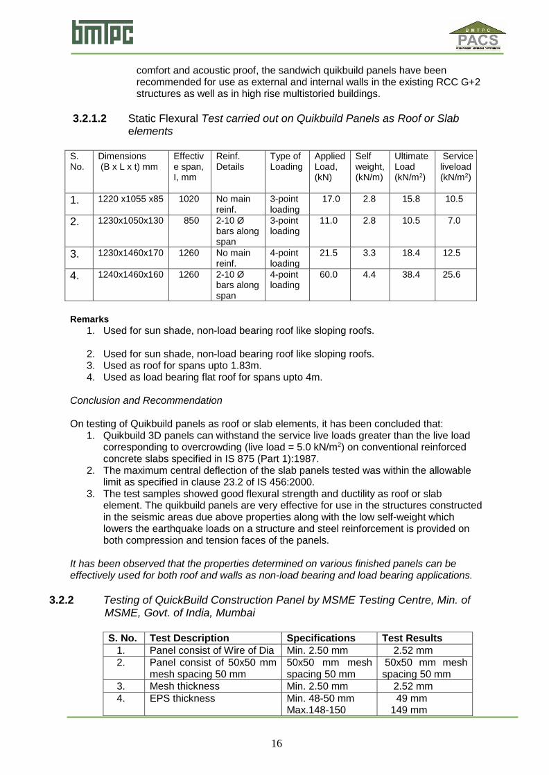
3.2.1.2 Static Flexural Test carried out on Quikbuild Panels as Roof or Slab
elements
S. No.
Dimensions (B x L x t) mm
Effective span, I, mm
Reinf. Details
Type of Loading
Applied Load, (kN)
Self weight, (kN/m)
Ultimate Load (kN/m2)
Service liveload (kN/m2)
1. 1220 x1055 x85 1020 No main reinf.
3-point loading
17.0 2.8 15.8 10.5
2. 1230x1050x130 850 2-10 Ø bars along span
3-point loading
11.0 2.8 10.5 7.0
3. 1230x1460x170 1260 No main reinf.
4-point loading
21.5 3.3 18.4 12.5
4. 1240x1460x160 1260 2-10 Ø bars along span
4-point loading
60.0 4.4 38.4 25.6
Remarks
1. Used for sun shade, non-load bearing roof like sloping roofs.
2. Used for sun shade, non-load bearing roof like sloping roofs. 3. Used as roof for spans upto 1.83m. 4. Used as load bearing flat roof for spans upto 4m.
Conclusion and Recommendation On testing of Quikbuild panels as roof or slab elements, it has been concluded that:
1. Quikbuild 3D panels can withstand the service live loads greater than the live load corresponding to overcrowding (live load = 5.0 kN/m2) on conventional reinforced concrete slabs specified in IS 875 (Part 1):1987.
2. The maximum central deflection of the slab panels tested was within the allowable limit as specified in clause 23.2 of IS 456:2000.
3. The test samples showed good flexural strength and ductility as roof or slab element. The quikbuild panels are very effective for use in the structures constructed in the seismic areas due above properties along with the low self-weight which lowers the earthquake loads on a structure and steel reinforcement is provided on both compression and tension faces of the panels.
It has been observed that the properties determined on various finished panels can be effectively used for both roof and walls as non-load bearing and load bearing applications.
3.2.2 Testing of QuickBuild Construction Panel by MSME Testing Centre, Min. of MSME, Govt. of India, Mumbai
S. No. Test Description Specifications Test Results
1. Panel consist of Wire of Dia Min. 2.50 mm 2.52 mm
2. Panel consist of 50x50 mm mesh spacing 50 mm
50x50 mm mesh spacing 50 mm
50x50 mm mesh spacing 50 mm
3. Mesh thickness Min. 2.50 mm 2.52 mm
4. EPS thickness Min. 48-50 mm Max.148-150
49 mm 149 mm
17
mm
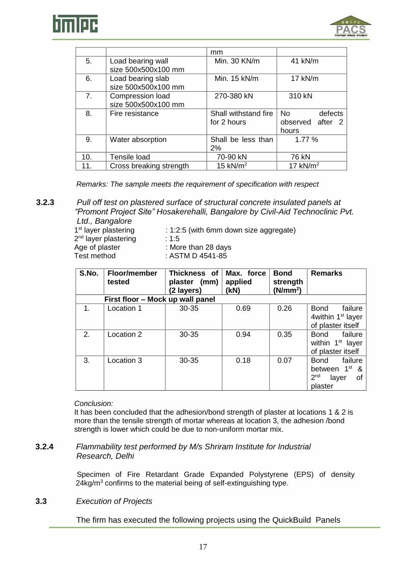
5. Load bearing wall size 500x500x100 mm
Min. 30 KN/m 41 kN/m
6. Load bearing slab size 500x500x100 mm
Min. 15 kN/m 17 kN/m
7. Compression load size 500x500x100 mm
270-380 kN 310 kN
8. Fire resistance Shall withstand fire for 2 hours
No defects observed after 2 hours
9. Water absorption Shall be less than 2%
1.77 %
10. Tensile load 70-90 kN 76 kN
11. Cross breaking strength 15 kN/m2 17 kN/m2
Remarks: The sample meets the requirement of specification with respect
3.2.3 Pull off test on plastered surface of structural concrete insulated panels at “Promont Project Site” Hosakerehalli, Bangalore by Civil-Aid Technoclinic Pvt. Ltd., Bangalore
1st layer plastering : 1:2:5 (with 6mm down size aggregate) 2nd layer plastering : 1:5 Age of plaster : More than 28 days Test method : ASTM D 4541-85
S.No. Floor/member tested
Thickness of plaster (mm) (2 layers)
Max. force applied (kN)
Bond strength (N/mm2)
Remarks
First floor – Mock up wall panel
1. Location 1 30-35 0.69 0.26 Bond failure 4within 1st layer of plaster itself
2. Location 2 30-35 0.94 0.35 Bond failure within 1st layer of plaster itself
3. Location 3 30-35 0.18 0.07 Bond failure between 1st & 2nd layer of plaster
Conclusion: It has been concluded that the adhesion/bond strength of plaster at locations 1 & 2 is more than the tensile strength of mortar whereas at location 3, the adhesion /bond strength is lower which could be due to non-uniform mortar mix.
3.2.4 Flammability test performed by M/s Shriram Institute for Industrial Research, Delhi
Specimen of Fire Retardant Grade Expanded Polystyrene (EPS) of density 24kg/m3 confirms to the material being of self-extinguishing type.
3.3 Execution of Projects
The firm has executed the following projects using the QuickBuild Panels

18
as per the details given below:
S. No.
Name of the Person/ Organization
Address Period of completion
1. Christ College Kilacherry, Mappedu (T N) February 2012
2. Amrith Anumolu Moinabad, Ranga Reddy (A P)
May 2013
3. Meridian White Field, Bangalore May 2013
4. Ravi Mandva Moinabad, Ranga Reddy (A P)
August 2013
5. Bethany School Koramangalka, Bangalore October 2013
6. Sure Energy Systems Pvt. Ltd.
Hyderabad (AP) November 2013
7. Builders & Construction Enterprises
Vasanth Nagar, Coimbatore (T N)
December, 2013
8. VTRC Ponmeni, Madurai (TN) December, 2013
9. Omplas Systems Gerugambakkam, Chennai January 2014
10. Vineetha Industries Adugodi, Bangalore January 2014
11. SERC Taramani, Chennai (TN) February 2014
12. TEFILAH Fraser Town, Bangalore May 2014
13. VME Reality Chembarabakkam (TN) May 2014
14. KPCL Wood House Kovalam (TN) August 2014
15. Champs Empowering Education
Hyderabad (AP) August 2014
19
This certificate holder shall satisfy the following conditions: 4.1 The certificate holder shall continue to have the product reviewed by BMBA. 4.2 The product shall be continued to be manufactured according to and in
compliance with the manufacturing specifications and quality assurance measures which applied at the time of issue or revalidation of this certificate. The Scheme of Quality Assurance separately approved shall be followed.
4.3 The quality of the product shall be maintained by the certificate holder.
Complete testing facilities shall be installed for in-process control. 4.4 The product user should install, use and maintain the product in accordance with
the provisions in this Certificate. 4.5 This certificate does not cover uses of the product outside the scope of this
appraisal. 4.6 The product is appraised against performance provisions contained in the
standards listed in Part-V. Provisions of any subsequent revisions or provisions introduced after the date of the certificate do not apply.
4.7 Where reference is made in this Certificate to any Act of Parliament of India,
Rules and Regulations made there under, statutes, specifications, codes of practice, standards etc. of the Bureau of Indian Standards or any other national standards body and the International Organization for Standardization (ISO), manufacturer’s company standards, instruction/manual etc., it shall be construed as reference to such publications in the form in which they were in force on the date of grant of this Certificate (and indicated in Part V to this Certificate)
4.8 The certificate holder agrees to inform BMBA of their clients with details of
construction on six monthly basis. 4.9 The certificate holder agrees to provide to BMBA feedback on the complaints
received, the redressal provided, and the time taken to provide redressal on complaint to complaint basis as soon as redressal is provided. BMBA agrees to provide the certificate holder the user feedback received by it, if any.
4.10 If at any time during the validity period, PACH is unable to fulfill the conditions
in his PAC, he should on his own initiative suspend using the PAC and notify Chairman, TAC the date from which he has suspended its use, the reason for suspension and the period by which he will be able to resume. He shall not resume without the prior permission of BMBA. He shall also inform, simultaneously, his agents, licensees, distributors, institutional, government, public sector buyers, other buyers and all those whom he has informed about his holding the PAC. He shall also inform all those who buy his product(s) during the period of suspension. He shall provide to BMBA at the earliest the list of who have been so informed by him.
PART 4 STANDARD CONDITIONS
20
4.11 In granting this Certificate, BMBA takes no position as to:
(a) The presence or absence of patent or similar rights relating to the product; (b) The legal right of the Certificate holder to market, install or maintain the product; (c) The nature of individual installations of the product, including methods of
workmanship. 4.12 BMTPC and the Board of Agreement of BMTPC (BMBA) take no position
relating to the holder of the Performance Appraisal Certificate (PACH) and the users of the Performance Appraisal Certificate (PAC) respecting the patent rights / copy rights asserted relating to the product / system / design / method of installation etc. covered by this PAC. Considerations relating to patent / copy rights are beyond the scope of the Performance Appraisal Certification Scheme (PACS) under which this PAC has been issued. PACH and users of this PAC are expressly advised that determination of the Claim / validity of any such patent rights / copy rights and the risk of infringement of such rights are entirely the responsibility of PACH on the one hand and that of the users on the other.
4.13 It should be noted that any recommendations relating to the safe use of the
product which are contained or referred to in this Certificate are the minimum standards required to be met with when the product is installed, used and maintained. They do not purport in any way to restate or cover all the requirements of related Acts such as the Factory Act, or of any other statutory or Common Law duties of care, or of any duty of care which exist at the date of this Certificate or in the future, nor is conformity with the provisions of this Certificate to be taken as satisfying the requirements of related Acts.
4.14 In granting this Certificate, BMTPC and BMBA does not accept responsibility to
any person or body for any loss or damage, including personal injury, arising as a direct or indirect result of the use of this product.
4.15 The certificate holder indemnifies BMBA, its officers and officials involved in this
assessment against any consequences of actions taken in good faith including contents of this certificate. The responsibility fully rests with the certificate holder and user of the product.
4.16 The responsibility for conformity to conditions specified in this PAC lies with the
manufacturer who is granted this PAC. The Board (BMBA) will only consider requests for modification or withdrawal of the PAC.
4.17 The PAC holder shall not use this certificate for legal defense in cases against
him or for legal claims he may make from others. Place: New Delhi Chairman TAC & for and on behalf of Date of issue: …………….. Member Secretary, BMBA
21
PART 5 LIST OF STANDARDS & CODES USED IN ASSESSMENT
5.1 These Standards are referred for carrying out particular tests only and do not specify the requirement for the whole product as such. 5.1.1 IS 456:2000 -- Code of practice for plain and reinforced concrete 5.1.2 IS 516:1959 -- Method of tests for strength of concrete 5.1.3 IS 875(Part 1):1987 -- Code of practice for design loads for buildings and structures 5.1.4 IS 4671:1984 – Specifications for expanded polystyrene for thermal insulation purposes 5.1.5 IS 4326:1993 – Code of Practice for Earthquake Resistant Design and Construction of Buildings 5.1.6 IS 4759:1996 – Hot Dip Zinc Coating on Structural Steel Products 5.1.7 IS 10748:2004 – Specifications for Hot Rolled Steel Strip for welded tubes and pipes 5.2 Company Standards of the PAC holder – The branded design & specifications of the raw materials and finished product are as submitted by the manufacturer. The PAC holder has to make available the company standards to the consumers according to which testing have been done.


23
PART 6 ABBREVIATIONS
Abbreviations BMBA Board of Agreement of BMTPC BMTPC Building Materials and Technology Promotion Council CPWD Central Public Works Department ED Executive Director of BMTPC IO Inspecting Officer MS Member Secretary of BBA PAC Performance Appraisal Certificate PACH PAC Holder PACS Performance Appraisal Certification Scheme SQA Scheme of Quality Assurance TAC Technical Assessment Committee (of BMBA)

24
Performance Appraisal Certification Scheme - A Brief
Building Materials & Technology Promotion Council (BMTPC) was set up by the Government of India as a body under the Ministry of Housing &Urban Poverty Alleviation to serve as an apex body to provide inter-disciplinary platform to promote development and use of innovative building materials and technologies laying special emphasis on sustainable growth, environmental friendliness and protection, use of industrial, agricultural, mining and mineral wastes, cost saving, energy saving etc. without diminishing needs of safety, durability and comfort to the occupants of buildings using newly developed materials and technologies. During the years government, public and private sector organizations independently or under the aegis of BMTPC have developed several new materials and technologies. With liberalization of the economy several such materials and technologies are being imported. However, benefits of such developments have not been realized in full measure as understandably the ultimate users are reluctant to put them to full use for want of information and data to enable them to make informed choice. In order to help the user in this regard and derive the envisaged social and economic benefits the Ministry of Housing &Urban Poverty Alleviation has instituted a scheme called Performance Appraisal Certification Scheme (PACS) under which a Performance Appraisal Certificate (PAC) is issued covering new materials and technologies. PAC provides after due investigation, tests and assessments, amongst other things information to the user to make informed choice. To make the PACS transparent and authentic it is administered through a Technical Assessment Committee (TAC) and the BMTPC Board of Agreement (BMBA) in which scientific, technological, academic, professional organizations and industry interests are represented. The Government of India has vested the authority for the operation of the Scheme with BMTPC through Gazette Notification No. 1-16011/5/99 H-II in the Gazette of India No. 49 dated 4th December, 1999. Builders and construction agencies in the Government, public and private sectors can help serve the economic, development and environmental causes for which the people and Government stand committed by giving preference to materials and technologies which have earned Performance Appraisal Certificates. Further information on PACS can be obtained from the website: www.bmtpc.org
25
ANNEX I (Clause 1.5.2) BUILDING MATERIALS & TECHNOLOGY PROMOTION COUNCIL QUALITY ASSURANCE PLAN for QUIKBUILD 3D PANELS
S. No. Stage/ Description Product Features Measurement
Means
Frequency of
Testing
A. E Welded Mesh
1. Acceptance of the raw
materials i) Steel Mesh
ii) Polystyrene (EPS)
Amount of material, Visual
inspection, Specifications
verification and
Dimensional controls
Quantity, Appearance &
completeness/ Brand,
Compliance of material
and Dimensions as per
manufacturer
Specifications
Visual, Vernier
Caliper and Tape
measure
Every Lot
2. Straightening and cutting
wire
Coil steel wire straightening
and cutting in the right size
of the longitudinal and
transversal wires
Dimensions and
Condition of material as
per manufacturer
Specifications
Visual and Tape
measure
Every Length
3. Electro welding
Steel wires welding to
obtain a mesh
Dimensions and
Orthogonally as per
manufacturer
Specifications
Tape measure Every dimension
of the panels
4. Shaping polystyrene
Cutting the polystyrene
panels from the blocks in
right dimensions
Dimensions as per
manufacturer
Specifications
Tape measure
and Vernier
caliper
Every dimension
of the panels
5. Welding/Assembling
panels
Assembling electro welded
mesh and polystyrene panels
Dimensions and
Orthogonally as per
manufacturer
Specifications
Tape measure
and Vernier
caliper
Every dimension
of the panels
B. Raw Materials
1. Zinc Coated Drawn Steel
Wire Mesh
Steel mesh of thickness
2.0, 2.5 & 3.0 mm, zinc
coating shall be 60gm/m2
and tensile strength shall
be 880 MPa,
As per MTC and
Company
Standard
Every Lot
2. Expanded Sintered
Polystyrene(ESP
Density shall not be less
than 14 kg/m3, Length
shall be 2.0 to 5.0 m,
Width shall be 1.210 m
and thickness shall be
50,80 &100 mm
As per MTC and
Company
Standard
Every Lot
26
ANNEX II (Clause 1.5.2) PROCESS FLOW CHART
27
ANNEX III CONSTRUCTION DRAWINGS
Reinforcement for Foundation Fig. 7
28
Erection of Wall Panel Fig. 8
29
Panel Connection Detail Fig. 9
30
Wall Corner Connection Detail Fig. 10
31
Wall Intersection Joint Detail Fig. 11
32
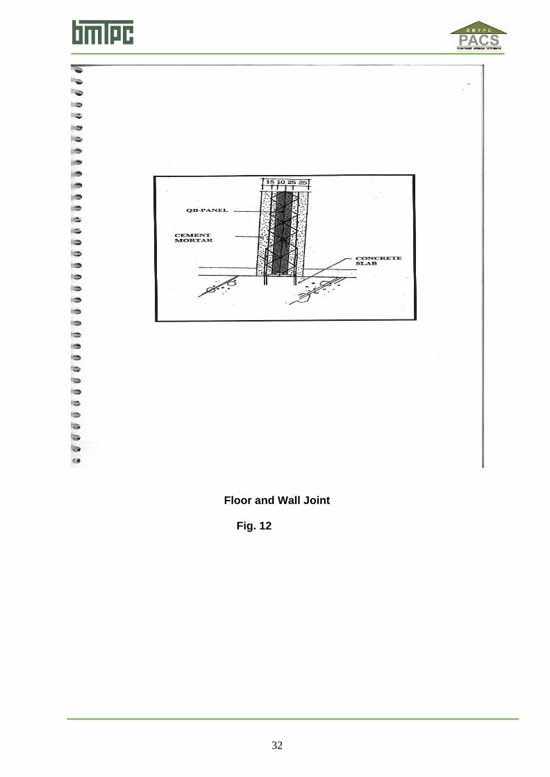
Floor and Wall Joint Fig. 12
33
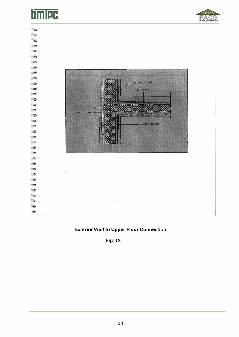
Exterior Wall to Upper Floor Connection Fig. 13
34
Typical Window Opening and Reinforcement Fig. 14

35
Typical Door Opening and Reinforcement Fig. 15

36
Wall Panel Erection Fig. 17 Detail of Joint Rods Fig. 16 Wall to Roof Joint Fig. 16
re
ad
er’
s
att
en
tio
n
wi
th
a
gr
eat
qu
ot
e
fro
m
th
e
do
cu
m
en
t
or
us
e
thi
s
sp
ac
e
to
e
m
ph
asi
ze
a
ke
y
po
int
.
To
pl
ac
e
thi
s
te
xt
bo
x
an
y
w
he
re
on
th
e
pa
ge
,

37
Wall Panel Erection Fig. 17
38
Window Cutouts
Fig. 18
39
Concealed Wiring & Plumbing Details
Fig. 19

40
Plastering Fig. 20
41
Roof Panel Fixing Fig. 21
42
Roofing Work
Fig. 22

43
Finishing Fig. 23

44
Utility Fittings Fig. 24


![Contract Holder: [NAME] [ADDRESS] [CITY ST ZIP](https://img.pdfslide.us/doc/110x75/616fea292f23561c921ae2ef/contract-holder-name-address-city-st-zip-.jpg)