Embed Size (px)
Citation preview

1
NAHAD Hose Safety Institute Whitepaper: Eye on Safety and Reliability for Liquid Vacuum Operations
Industry Best Practices for Liquid Vacuum Hose Assembly Applications
Abstract: This whitepaper represents an on-going effort to document best practices for ensuring safety and reliability of Liquid Vacuum hose assembly applications. It is intended to represent the consensus of contributing companies and organizations as to the recommended best practices in the design, fabrication, and on-going maintenance of hose assemblies used in Vacuum applications, specifically Liquid Vacuum work. (See the end of this document for a list of contributing companies.) Intended benefits of this paper include:
Providing a common lexicon – ensuring that the hose industry and the end user understand what the other is referring to
helping end users get the right hose for the application – and understand the variables involved; hose compatibility with the material being transported is crucial
Understanding the criticality of knowing what is being “sucked up” – investment up front in purchasing the right hose for the job is cheaper than the costs downstream of cleaning up a spill or dealing with an accident; regulatory issues/costs are hugely important and relevant
This paper is limited to hoses used for liquid vacuum operations with chemicals, or petroleum products (red box next page); it will not address dry vacuum operations or water applications, nor will it explicitly address tank truck industry applications.

2
Liquid Vacuum work is a staple of the pulp, paper, petrochemical, refining, automotive, steel,
etc. industries, in applications ranging from routine to time critical. Vacuum trucks have
become standard operating equipment for refineries, chemical plants, paper mills, and power
plants.
Providing services such as moving waste, evacuating blast water, covering line breaks, skimming
ponds, removing catalyst, vacuuming sands and media, transporting acids or pond bugs,
lowering oil sumps, maintaining water levels during flooding, and managing spills are now
common service lines for industrial cleaning companies to offer.
Liquid Vacuum service has the potential to be a high risk craft if not managed properly. Environmental and Safety considerations hold an equally high prominence. This white paper is part of a comprehensive approach to ensure worker safety and environmental stewardship, one which requires equal effort in three critical areas: behavior based programs, standard equipment design and maintenance, and employee training to the standard. While each area is of equal importance, this paper focuses on best practices in standard equipment design relating to hose assemblies based on input from Vacuum service contractors and hose and equipment manufacturers and distributors.
This whitepaper was developed under the auspices of the Hose Safety Institute©, operated by NAHAD, The Association for Hose and Accessories Distribution. The Institute provides a powerful forum for
Vacuum Hose
Liquid Vacuum
Petroleum Suction/Discharge
Chemical Suction/Discharge
Waste Water (industrial, municipal)
Dry Vacuum Tank Truck

3
distributors, manufacturers, suppliers, end-users and industry organizations to support and promote hose assembly safety, quality and reliability, across all markets and industries.
The Institute’s core deliverables are the NAHAD Hose Assembly Guidelines; performance standards for hose assembly specification, design, fabrication, handling and management as provided by qualified NAHAD Hose Safety Institute Members.
The Institute is managed by NAHAD’s Standards Committee and supported by the end-users and
industry experts serving on the Hose Safety Institute Advisory Council.

4
Table of Contents Background ................................................................................................................................................... 5
Objective ....................................................................................................................................................... 5
Pre-Sale Considerations ................................................................................................................................ 7
Definitions ................................................................................................................................................. 7
Specification and Design – STAMPED .................................................................................................... 11
Hose Assembly Fabrication Considerations .............................................................................................. 14
In-Service Considerations........................................................................................................................... 16
Hose Management Program.................................................................................................................. 16
Service life ............................................................................................................................................... 17
Hose Use and Care .................................................................................................................................. 17
Handling .............................................................................................................................................. 17
Operation ............................................................................................................................................ 17
Storage ................................................................................................................................................ 18
Inspections .......................................................................................................................................... 18
Visual Inspection Checklist .................................................................................................................. 20
Cleaning ............................................................................................................................................... 25
Participating Companies: ............................................................................................................................ 26
Appendix A: Visual Inspection Checklist Tool ........................................................................................... 27

5
Background Liquid Vacuum services have grown over the last 25 years. Hose management policy and procedures vary across services providers.
o Lack of a comprehensive hose management policy, including marking, inspection, and testing, can lead to hose failure, injury or environmental incident.
o Customers, such as major petrochemical companies, have elevated their expectations and now seek proof of a hose management policy in order to perform work in their facilities
o Operational consistency across Liquid Vacuum companies, their sites and divisions is required, but few programs offer a complete hose life cycle solution; therefore service provider’s costs vary greatly
o No common industry standards exist for Liquid Vacuum hose, relating to inspection, testing, service life, or common definitions of terms
This paper addresses the need to improve the level of safety for the sourcing, fabrication, and service life issues of Liquid Vacuum hose applications, largely in industrial cleaning applications. Safety processes increase costs, but for these applications, they are critical.
Objective This paper delineates recommended best practices to provide guidance to end-users, distributors, and others involved in this business.
Strategic business model Liquid Vacuum hoses are one of the most critical components of Liquid Vacuum Operations. Hose reliability and safety directly affect a provider’s ability to deliver safe, environmentally reliable, productive service. Following practices that increase reliability and safe performance of these components is essential for the continued health and vitality of the business.
Top line impact Clients are attracted to vendors who can provide service in the most safe, environmentally sound and cost efficient manner. Providers who can demonstrate processes and strategies which insure the highest standards of hose integrity will gain more business opportunities and consequently grow their top line revenue.
Bottom Line Impact Injuries, environmental impacts and downtime due to hose failures lead to costly direct and indirect expenses which will erode any top line revenue gains. Hoses that have higher integrity protect profits.
Environmental Impact Liquid Vacuum hose failures can lead to environmental losses which can range from relatively minor to reportable quantity (RQ) level. RQ losses can significantly impact the

6
environment and lead to EPA or DEQ inspections, regulatory penalties, fines and work delays.
Human cost Employees who work for companies with strong hose management programs enjoy higher confidence in their equipment which leads to higher morale and productivity. Liquid Vacuum hose failures can lead to significant injuries, restricted or lost workdays and large medical costs.
This whitepaper can be added to over time, may include sections on pre-sale considerations, post-sale in-service issues/recommendations, and whatever else the team deems appropriate. Primary audience:
Risk Management Managers
EH&S Managers
Senior Management at Liquid Vacuum Services companies
Client Maintenance Managers
WJTA-IMCA members (Water Jet Technology Association - Industrial and Municipal Cleaning Association)
Hose and Accessories Distributors Call to action: This white paper is a first step towards documenting best practices for liquid vacuum service for the hose and accessory industry.

7
Pre-Sale Considerations
Definitions
API – American Petroleum Institute Bonding – Bonding and grounding provide controls to help eliminate static electricity. Bonding provides electrical connections between isolated conductive parts of a system to equalize their electrical potential (voltage). Electrical resistance between two directly bonded connections should not exceed 10 ohms. Hose bonding refers to the continuous connection between the metal end of the hose, the helix wire inside the hose, and the connection to the liquid vacuum truck to equalize the static charge built up during the vacuum process and the process of maintaining a resistance level of <10ohms. Note: this applies to single lengths of hose only; multiple hoses strung together may need to be treated differently.
Grounding – Refers to the ability of the static charge to trace a path to a grounding point to “mother earth” for dissipation, and should be monitored to a level of <1000ohms. An electrical resistance <10 ohms should be achieved between the truck and the ground point.
Electrical Continuity Test – Electrical continuity testing determines if an electrical path can be established between two points; for hose assemblies, refers to testing the assembly to determine if there is a grounding path between end fittings. Reference NFPA 77 and API 2219 for additional detail.
CFM – Cubic Feet per Minute Coupling – also known as “fitting” – a device attached to the end of a hose to facilitate connection.
Cam and Groove couplings, also called cam lock fittings or couplings. Cam and groove is a kind of quick connect coupling usually used in most industries as a hose connection. This kind of coupling is popular because it is considered to be a simple and economical way of re-connecting and disconnecting. A Cam and groove fitting can be used in a system where rapid filling of chemical drums takes place. It can be used by factories that have needs of dye, paint and ink medium transfers. It is used where frequent changes of hoses are required to find the right mix. It also suitable for petroleum trucks, etc.

8
Part C Hose End “Hose Barb Coupler” (a coupler is always the female portion of a Cam and Groove fitting) Part E Hose End “Hose Barb Adaptor” (an adaptor is always the male portion of a cam and Groove fitting)
Female Cam & Groove Female Cam & Groove Male Cam & Groove (with Locking Arms) (without Locking Arms) General Uses: Cam and Groove female couplers and male adapters are used as a means of quickly coupling small to large hose assemblies. They connect hose to hose or hose to a pipe system for the purpose of transferring liquids. Connections are made by inserting the male into the female coupler and rotating ALL the cam arms into their locked positions.
Note: Cam and Groove couplings are not recommended for any type of
compressed gas service, including steam or air.

9
Gaskets – the chemical compatibility of the media and the gasket material needs to be verified to optimize service life and the effectiveness of the seal.
Hose - Vacuum hose, Liquid Vacuum Hose – Hoses used to transfer material to and from a liquid vacuum truck and a liquid source such as a sump, pond, tank, etc… The two main types of Liquid Vacuum hoses are Petroleum Suction & Discharge Hose and Chemical Suction & Discharge Hose.
Chemical Suction and Discharge Hose (plastic or rubber lined) – These hoses are typically used for the transfer of low or high pH liquids under pressure, gravity flow, or suction. Chemical rubber hoses manufactured from plastic liners such as Cross-Linked Polyethylene (XLPE) or Ultra-High Molecular Weight Polyethylene (UHMWPE), Nylon or Fluoropolymer (Teflon*) Hose. The hose and couplings, and gaskets or seals selected for use must be compatible with the chemical(s) to be conveyed under the stated service conditions. The application temperature range is -40ºF (-40°C) to +350ºF (+177°C) but that range may be shifted higher or lower depending on hose tube and construction. Hose can be used in a vacuum application as a suction hose if constructed with a helical wire or reinforcement that will support a vacuum. Note: there are other considerations beyond a helix for creating a hose that will support a vacuum, but helical wire and/or reinforcements predominate – make sure the hose is specified for liquid vacuum use, constructed with appropriate ways to dissipate static buildup. Petroleum Suction and Discharge Hose – These hoses are typically used for transfer of moderate pH liquids such as gasoline and other petroleum based products under pressure, gravity flow or suction. Typical pressures of up to 150 psi. Typical Constructions Include: Oil, Gasoline, Petroleum and Biodiesel Suction and Discharge. This hose is designed for petroleum based products, and is constructed of petroleum based materials such as oil resistant tubing. Consult manufacturer for compatibility of blended fuels, such as biodiesel and E85 fuels.
Hose can be used in a vacuum application as a suction hose if constructed with a helical wire and/or reinforcement that will support a vacuum. The normal application temperature range is 35°F to 200°F (2°C to 93°C) but can go higher depending on the hose

10
tube and construction, or can go lower (e.g., arctic fuel suction and discharge hose) depending on hose tube and construction. -25 – 180F is suggested. Depending on the
construction, usable temperature range may be shifted higher or lower.
Hydrostatic Proof Test - A hydrostatic test is a way in which the suction/discharge hose is tested for strength and leaks. The test involves filling the hose with a liquid, usually water, which may be dyed to aid in visual leak detection, and pressurization of the vessel to the specified manufacturer test pressure. Sometimes referred to as Proof testing or testing that “proves” the finished hose assembly meets the pressure rating required by the application for which it will be used, and that the end fittings have been correctly fitted and the assembly is leak free. Life Cycle – The time frame in which an asset can be utilized before the asset should be destroyed and replaced. Safety Data Sheet – A document containing information and instruction on hazardous materials present in the workplace; SDS’s contain detail about the hazards and risks associated to the substance and the requirements for its safe handling as well as actions to be taken in the event of fire, spill, or overexposure. Vacuum hose, Liquid Vacuum Hose – Hoses used to transfer material to and from a liquid vacuum truck and a liquid source such as a sump, pond, tank, etc… The two main types of Liquid Vacuum hoses are Petroleum Suction & Discharge Hose and Chemical Suction & Discharge Hose. Vacuum Truck – A transportable vacuum system consisting of vacuum pump, vacuum cargo tank, and associated tools and accessory equipment mounted on a motor vehicle. Wastewater Suction & Discharge Hose – Industrial and municipal. Not covered within this paper.

11
Specification and Design – STAMPED An effective way to identify application factors that need reviewing prior to defining the proper specifications of a hose assembly is to remember the simple acronym STAMPED. The STAMPED acronym stands for the 7 major information areas required to provide a quality hose assembly for the customer, as follows: S stands for SIZE; I.D. and length; any O.D. constraints
overall length should be specified to include fittings
tolerances need to be specified if special requirements exist
I.D., O.D. and overall length of the assembly
To determine the replacement hose I.D., read the layline printing on the side of the original hose. If the original hose layline is painted over or worn off, the original hose must be cut and inside diameter measured for size.
The inside diameter of the hose must be adequate to keep pressure loss to a minimum, maintain adequate flow, and avoid damage to the hose due to heat generation or excessive turbulence.
Length tolerances should be considered for all types of hose assemblies. Pressure Loss - The flow rate of the system in conjunction with the inside diameter of the hose
will dictate the pressure loss through the hose. Please consult your hose supplier for specific recommended flow rates.
Loading and unloading flow rate is impacted by the inside diameter of the hose. Note: hoses with a large OD will likely require special handling.
T stands for TEMPERATURE of the material conveyed and environmental conditions
How hot is the material being conveyed
Are there factors such as heat sources in the environment in which the hose will be used
Continuous (average) and minimum and maximum temperatures have to be specified for the environment
Care must be taken when routing hoses near hot manifolds and in extreme cases a heat shield may be necessary.
In subfreezing temperatures, care must be taken to keep water flowing through hoses. All hoses must be drained on completion of the project. In starting in subfreezing conditions, hoses must be flushed to remove ice crystals prior to installing the tip.
Other things to consider: maximum intermittent ambient temperature, fluid temperature, ambient temperature and maximum temperature.
A stands for the APPLICATION, the conditions of use
Configuration/routing (add a sketch or drawing if applicable) o is the hose hanging, laying horizontally, supported, unsupported (orientation and
aspect of the hose); routing up or down hills – requirements for pressure calculations (feet of incline etc.) – head pressure requirements; pull forces if vertical

12
routing is included o what else is attached to the hose, any external load on the hose o bend radius requirements, flexibility
Immersion in the material being conveyed
Quantify anticipated movement and geometry of use requirements
Intermittent or continuous service
Indoor and outdoor use
Unusual mechanical loads (vehicle traffic, etc.) Excessive abrasion External conditions – abrasion, oil (specify type), solvents (specify type), acid (specify type
and concentration), ozone, salt water, ultraviolet (UV) radiation (sunlight), geographic temperatures (e.g., Alaska vs. Louisiana)
Hose now in use o Type of hose o Service life being obtained and description of failure or source of customer
dissatisfaction strength and frequency of impulsing or pressure spikes non-flexing applications (static), flexing applications (dynamic)
M stands for the MATERIAL or MEDIA being conveyed, type and concentration
Are there special requirements for this hose tube o Any special specifications (or agency requirements) that need to be considered (e.g.,
FDA, API) o Will the material be continuously flowing, or sit in the hose for long periods of time
(specify)
Media velocity, flow rate
Weight of media (specific gravity)
Chemical name/concentration (MSDS)
Solids, description and size
Fluid Compatibility - Some applications require specialized oils or chemicals to be conveyed through the system. Hose selection must assure compatibility of the hose tube. In addition to the hose materials, all other components, which make up the hose assembly (hose ends, o-rings, etc…), must also be compatible with fluid being used. Depending on the fluid, your hose supplier may lower the maximum temperature or pressure rating of the assembly. When selecting any hose assembly, always consult your hose supplier’s recommendations.
Temperature of product Corrosively of product; potential corrosiveness of mixed media (resulting from improperly
cleaned hoses) P stands for the PRESSURE to which the assembly will be exposed (or vacuum for negative pressure or inches of mercury)
System pressure, including pressure spikes. Hose assembly working pressures must be equal to or greater than the system pressure. Pressure spikes greater than the maximum

13
working pressure will shorten hose life and must be taken into consideration.
Temperature implications
Maximum Operating Pressure - This is the maximum pressure that the system should be exposed to in normal operating conditions. This pressure should be dictated by the relief setting of the system. Both the hose and hose end should not be rated to a pressure less than the maximum operating pressure of the system. Pressure Spikes - When a system is subjected to a large load in a short period of time, the system pressure can overshoot the relief setting and exceed the maximum operating pressure. Frequent pressure spikes can reduce the life of hose assemblies.
Vacuum as measured in inches of mercury (HG)
Hose routing (will the hose be straight or bent for the application) impacts the hose requirements; some hoses will hold a vacuum while straight, but will collapse if bent.
E stands for ENDS; style, type, orientation, attachment methods, etc.
Specify end style
Materials and dimensions (steel, stainless, etc.)
Conductivity requirements
Specify attachment method – banding, crimped
Consideration should be given to the lowest rated component (hose, fitting, and attachment) in determining overall MWP of the entire hose system.
Clarify sleeves and ferrules (add to fabrication portion)
Specify impact of any pull forces, if vertical routing of hose assembly is anticipated
D stands for DELIVERY
Specific to customer requirements
Testing and certification requirements
Any special packaging requirements
Any special shipping requirements
Tagging requirements
When analyzing hose failures, note there can be multiple root causes based on the above
parameters from STAMPED.

14
Hose Assembly Fabrication Considerations
Fabrication of hose assemblies should be done in accordance with industry best practices such as NAHAD’s Hose Assembly Guidelines, supplemented by specific manufacturer instructions. As part of the fabrication process, assemblies should be tested to ensure the integrity of the product when first made; this is usually done through hydrostatic pressure testing, but may include vacuum testing if required by customer. Inspection and re-testing of in-service assemblies should be conducted annually. Field inspection should be conducted prior to each use as well as end of job use. (See the section on In-Service Considerations in this paper for more details.) For assembly handling, storage and shipping best practices, please refer to the appropriate sections found in NAHAD’s Hose Safety Institute Handbook©. Documentation of assemblies should be thorough and trackable in conformance with a formal hose management program including tagging of assemblies through a formal marking scheme, and a formal tracking process. See In-Service Considerations for more details. Specific remediation of hoses which have been taken out of service is beyond the scope of this document. Repair and Remediation of hoses should be done in accordance with industry best practices. Crimping and banding are both acceptable methods of attaching fittings/couplings to “Vacuum Hose” (chemical, petroleum transfer, material suction/discharge hoses). When crimping, the best practice is that all components (fittings/couplings, ferrules, sleeves) should be from the same manufacturer; if not, the Distributor should consult with the appropriate manufacturers, and verify the viability of the assembly via proper testing. Further, the procedures, process, and crimp specs should be based on manufacturer requirements. Components should be tested and verified by the manufacturer, as related to pressure and temperature requirements and should carry safety factors associated with the entire hose system; the full hose assembly should be properly tested by the Distributor.
Banding is also an acceptable attachment method. (Check with manufacturer for recommendations). Band clamps are typically placed behind a raised part of the barb, such that if the hose were to try and slip off, the clamp would have to expand to fit over the raised part, thus keeping the hose attached to the barb (see the Industrial Hose Fabrication guide for further details). When banding with a hand tool it’s imperative to properly install the clamp (bring the clamp material to its yield prior to completing the clamp installation) to achieve repeatability. (Contact your Hose Safety Institute distributor or manufacturer for methods).
NOTE: The overall Maximum Working Pressure of the entire hose system is determined by the component (hose, fitting, and attachment) with the lowest pressure rating, regardless of attachment method used. Repeatability and consistency of the fabrication process are crucial in yielding safe, reliable hose assemblies.

15
Note: when specifying the appropriate hose assembly to meet vacuum hose application requirements, it is important to consider pull forces on the coupling/connections based on any vertical elevation pull. Hose weight and media weight both need to be taken into consideration if the application includes vertical routing of the hose assembly. If this is the case, end pull forces need to be re-stated as equivalent psi requirements, depending on hose size. Appropriate fittings and connections need to be specified.

16
In-Service Considerations
Hose Management Program Hoses should be managed as an individual asset from fabrication of hose until end of useful life. Such management should include the following:
An asset management program should include the following o Methods to track hose from initial fabrication until end of hose life o Methods to alert end user companies of scheduled inspections o Methods to alert end user of end of life so hose can be removed from service o A policy of hose life expectancy o Records confirming results of inspection program and asset certification o Techniques for proper marking of assets (e.g., mechanically etched ferrules)
A proper use and care program should include the following o Manufacturer and Distributor recommendations o Proper handling of hose o Proper storage of hose o Do’s and Don’ts for hose handling while in service.
An inspection program should contain o Field visual inspection criteria o Periodic pressure test and integrity protocols
A failure inspection program should contain o Definition and Types of hose failures o Methods for reporting hose failures o Methods for investigation hose failures o Methods for implementing lessons learned across the organization
A training program should contain o All of the above programs o Documented hands on competency verification
Hoses should have documentation or markings on site which allows the user to easily confirm
A. What the hose is designed to load or unload B. Temperature rating C. Vacuum and Pressure rating D. Current Test Data

17
Service life The recommended service life of Vacuum hose is dependent on the care it receives, the application it is being used in, the material being transferred, cleaning processes, and a thorough inspection program. The human element is critical and can be mitigated only partially by good training programs, clear processes, etc. Variations in equipment (e.g., trucks), stress points, and other variables will all impact service life of the hose assembly. Organizations should focus on best practices in hose tracking: identifying what their experience has been with hose assemblies, capturing data from failures, and noting what trends emerge over time, allowing them to better forecast what to expect in terms of hose service life.
The object of the following testing and inspection procedures is to detect any weakness in a hose
assembly before the weakness causes failure of a hose in service.
It is imperative that hose, while in storage or in service, not be subjected to any form of abuse such as
kinking, exposure to an environment involving extremes of temperature, corrosive or oxidizing fumes or
liquids, oils and solvents, ozone, etc.
For chemical hose, care must be taken when different chemicals are conveyed in the same hose; the chemicals may react and shorten the service life of the hose. When it is impractical to disconnect the hose line after use, drain any remaining chemical from the hose.
Hose Use and Care
Handling
Crushing or kinking of the hose can cause severe damage to the reinforcement. Care should be
exercised to prevent mishandling. Do not drag the hose or lift large bore hose from the middle
of its length with the ends hanging down. Limit the curvature of the hose to that recommended
by the manufacturer and avoid sharp bends at the end fittings and at manifold connections.
Operation
Important: Personnel involved in an operation using chemical hose must use safety precautions
such as wearing eye or face protection, rubber gloves, boots, and other types of protective
·clothing. Pressures and temperatures are to be monitored to see that the hose is not exposed
to conditions above specified limits. Exceeding specified limits could injure the hose and result
in damage to property and serious bodily harm.

18
Never allow chemicals to drip on the exterior of a hose or allow hose to lay in a pool of
chemicals as the hose cover may not have the corrosion resistance of the tube. Should a
corrosive material come in contact with the reinforcing material, early failure could result. If
kinking or crushing occurs, examine the hose carefully, and, if the outside diameter is reduced
20% or less, the hose must be immediately subjected to a Hydrostatic Pressure test. If the
reduction in diameter is more than 20%, retire the hose from service.
Care must be taken when different chemicals are conveyed in the same hose; the chemicals
may react and shorten the service life of the hose. When it is impractical to disconnect the hose
line after use, drain any remaining chemical from the hose.
Storage Before placing chemical hose in storage, the hose must be completely drained and any potentially explosive vapors or corrosive residues flushed out. NOTE: Extreme care must be taken when flushing out a chemical hose with water; some chemicals, such as concentrated acids, may react with water and cause spattering. When flushing a hose, disposal of the effluent must be made in such a manner that environmental problems are not created. Chemical hose should be stored so that air can circulate through it—laid straight on a solid support. This procedure helps extend the life of the hose. Ideally, hose should be stored in a cool, dark, dry place.
Inspections A hose and fitting maintenance program is critical to maintaining a safe functional hose system and will reduce equipment down time and maintain peak operating performance. Hoses should be inspected and pressure tested in house or by a third party prior to placement into service and whenever a defect is suspected or at a minimum of annually. A visual inspection should be conducted prior to each use as well as end of job use. Retesting hose is a recommended procedure to insure the safe continued serviceability of hose assemblies. Retesting is recommended every 12 months. Inspections should include
Visual inspection
Pressure testing o New hoses and hoses for re-certification should be pressure tested at 1.5 times
maximum allowable working pressure for a minimum of 5 minutes; consult manufacturer for specific requirements. Note: the maximum allowable working pressure for a hose assembly is dictated by the component of the assembly (hose, fitting, etc.) with the LOWEST pressure rating.
o Hose assemblies shall be inspected and tested immediately after the hose is subjected to abnormal abuse such as: severe end pull, flattening or crushing or sharp kinking. Any hose that has been recoupled shall be proof tested and inspected before being placed in service.
Inspection Results Documentation

19
Visual Inspections
The operators of the hose are a company’s last line of defense against spills resulting from damaged hose. Companies should have training programs that educate the operators on what to look for before the hose is placed into service. The operators should be trained to always err on the side of safety and “When in doubt, remove the hose from service.” When inspecting hoses in service, attention should be paid to:
Removable protective covers
o Any cuts, gouges or tears in the cover which do not expose the reinforcement
should be repaired before the hose is returned to service. If the reinforcement is
exposed, retire the hose from service.
o Covers may show surface cracking or crazing due to prolonged exposure to
sunlight or to ozone. Such deterioration, which does not expose reinforcing
material, is not cause for retirement.
Carcass
o Look for any indication of kinking or broken reinforcement as evidenced by any
permanent distortion, longitudinal ridges, or bulges. Crushed or kinked spots
where the outside diameter of the hose is reduced by 20% or more of the
normal outside diameter shall require that the hose be retired from any service.
Hose containing kinked or crushed spots where the outside diameter is reduced
less than 20% may be used if the hose passes the hydrostatic tests.
Fittings
o All metals are subject to attack by various chemicals. Check with the
manufacturer to make sure that suitable end fittings, appropriate to both the
hose and the chemical being handled, are being used.
o Exposed surfaces of couplings, flanges and nipples shall be examined for cracks
or excessive corrosion. Either condition shall cause the hose to be retired from
service. Any evidence of coupling or nipple slippage on the hose is cause for
removing the hose from service.
The hose and fittings shall be visually inspected for:
A. Leaks at the hose fittings or in the hose. B. Damaged, separated or pulled back covers C. Cracked, damaged, deformed or badly corroded fittings.
D. Other signs of significant deterioration such as blisters.
E. Compromised reinforcement where the wires are exposed and show signs such as unwrapped, broken or corroded.
F. Dents, twists, or kinks G. Discoloration of color coded hose cover H. Verify test date and pressure is in conformity with requirements for the application. I. Fitting Thread and seat condition J. Verify condition and seating of gaskets

20
In addition to the above conditions, do not place any Liquid Vacuum Hose in service that has visible or exposed reinforcing wires (braids) and immediately remove from service if there are compromised reinforcing wires.
Visual Inspection Checklist Visually inspect hose before each use. Immediately remove Hoses from service upon finding any of the following conditions: External inspection:
Evidence of leaks at the hose fittings or in the hose. Damaged, separated or pulled back covers (de-lamination)
Cracked, damaged, deformed or badly corroded fittings Poorly crimped fittings – can’t see the hose through the crimp; ferrule and hose are
not fully engaged

21
Good fitting - part of the hose is coming out of a ‘hole’ in the crimp. That tells you the hose has been crimped all the way up to the top of the fitting. If you can’t see the hose then you don’t know how far up the hose has been inserted and crimped.
Issues with Cam & Groove fittings
Improperly banded hose: all of the buckles are in a line. Which may create a leak path and premature hose failure

22
Other signs of significant deterioration such as
blisters, soft or bulging hose cover gouging
wear weathering/dry rot
Compromised reinforcing wires.

23
Dents, twists, or kinks
Discoloration of color coded hose cover Verify test date and pressure is in conformity with requirements for the application. Check thread and seat connections
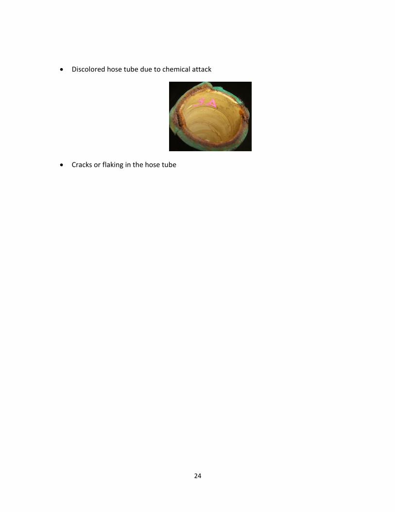
Internal Inspection: Small ID hoses are difficult to visually inspect without a special bore
camera. As the IDs get larger an internal inspection is possible. 2” ID and larger hoses offer the
ability to see several feet into the hose ID. What can be seen generally is representative of the
rest of the hose.
Look for any of the following:
Loose hose tube (tube de-lamination) near the coupling
24
Discolored hose tube due to chemical attack
Cracks or flaking in the hose tube

25
Cleaning
In many applications is best practice to clean each hose after each use. This prevents continued damage to the hose interior and couplings from the long term effects of potentially hazardous chemicals or the contamination of product when the hose is reused, and may improve hose service life.
The preferred process is typically accomplished by flushing the interior of the hose with water or a cleaning solution that is compatible with the hose tube. The temperatures used in this process should not exceed 212⁰ F for longer than 20 minutes. The pressure used to circulate or flush the hose must never exceed the Working pressure of the hose or coupling.
Cleaning solutions should be able to dissolve or remove the residue material in the hose assembly and must be compatible with the hose tube and couplings. All material flushed from the hose must be processed in accordance with EPA requirements.
Inserting cleaning devices (wands, rods or brushes, etc.) into the hose ID is not recommended due to the potential of damaging the hose tube.
Steam cleaning is not the preferred method for cleaning any hose due to the possibility of overheating the hose and coupling. If steam cleaning is necessary the below procedure is recommended:
a. The hose should be placed in a straight line with one end higher in elevation to permit draining from the lower open end.
b. Never use superheated steam (steam temperature going into the hose should not exceed the max temperature of the hose or 212⁰ F.)
c. Use a steam supply line not larger than ¾” ID into the adaptor to match the ID of the hose to be cleaned; the other end of the hose must be open and unrestricted.
d. Care must be taken to insure that the velocity of the steam injected in to the hose ID is minimal. A steam jet will damage the hose tube.
e. Steam cleaning duration not exceeding 15 minutes is recommended. f. Hose should be flushed with cool clean water afterwards.
Processes used to clean hoses in service can dramatically impact both the service life of the
hose and potential failures. Key considerations include:
Excessive abrasion (both chemical and physical)
Detergents/Degreasers/Solvents used in the cleaning process
Temperatures of cleaning solutions or water (steam injector guns)
Pressures of water used to clean the ID of industrial hoses

26
Participating Companies: Task Group members: GHX: Jim Reilly, Meg Adams, Jeff Davis PSC: Rick Pitman, Bradley Coble NAHAD: Debbie Mitchell Groendyke Transport: Steve Niswander Clean Harbors: Sean Benoit HydroChem: David Thompson
Dixon Valve: Hazen Arnold Campbell Fittings: Titus Jumper Novaflex: Tom Wise Marathon Petroleum – Roger Gautreau Band-It: Kelly Kinney, Alton Williams

27
Appendix A: Visual Inspection Checklist Tool
Visually inspect hose before each use. Immediately remove Hoses from service upon finding any of the following conditions: External inspection:
Evidence of leaks at the hose fittings or in the hose. Damaged, separated or pulled back covers (de-lamination) Cracked, damaged, deformed or badly corroded fittings Poorly crimped fittings – can’t see the hose through the crimp; ferrule and hose are not
fully engaged Note: For good crimps, part of the hose is coming out of a ‘hole’ in the crimp. That tells you the hose has been crimped all the way up to the top of the fitting. If you can’t see the hose then you don’t know how far up the hose has been inserted and crimped.
Issues with Cam & Groove fittings Improperly banded hose: all of the buckles are in a line. Which may create a leak path and
premature hose failure Other signs of significant deterioration such as
o blisters, soft or bulging hose o cover gouging o wear o weathering/dry rot
Compromised reinforcing wires. Dents, twists, or kinks Discoloration of color coded hose cover Verify test date and pressure is in conformity with requirements for the application. Check thread and seat connections
Internal Inspection: Small ID hoses are difficult to visually inspect without a special bore
camera. As the IDs get larger an internal inspection is possible. 2” ID and larger hoses offer the
ability to see several feet into the hose ID. What can be seen generally is representative of the
rest of the hose.
Look for any of the following:
Loose hose tube (tube de-lamination) near the coupling
Discolored hose tube due to chemical attack
Cracks or flaking in the hose tube