Embed Size (px)
Citation preview
SECURI1Th' INJFDR
NJ329
Copy RM L52GO8
•lit
E vl , .14 1
1% o r Y^11 ^
RESEARCH MEMORANDUM
INVESTIGATION OF THE LOW-SPEED
AERODYNAMIC CHARACTERISTICS OF A VARIABLE-SWEEP AIRPLANE
MODEL WITH A WING HAVING PARTIAL-SPAN CAMBERED-LEADING-
EDGE MODIFICATIONS
By Robert E. Becht and Andrew L. Byrnes, Jr.
Langley Aeronautical Laboratory Langley Field, Va.
CLASSIFICATION CHANGED TO UNCLASSIFIED
AUTHORITY: NLCA RESEARCH USTRACT NO.
UTE: JAN 11, 1956 CLASSIFIED DOCUMENT
This meterlal contains informaUon affecting the National Defense of the United States within the meaning of the espionage laws, Title 18, U.S.C., Sec.. 793 and 794, the transmission or revelation of which In any manner to unauthorized person Is prohibited by law.
NATIONAL ADVISORY COMMITTEE FOR AERONAUTICS
WASHINGTON September 16, 1952
NACA Wl-
O*ID!NT1AL
https://ntrs.nasa.gov/search.jsp?R=19930087330 2018-08-19T23:55:37+00:00Z
NACA RM L52GO8a CONFIDENTIAL
NATIONAL ADVISORY COMMITTEE FOR AERONAUTICS
RESEARCH MEMORANDUM
INVESTIGATION OF THE LOW-SPEED
AERODYNAMIC CHARACTERISTICS OF A VARIABLE-SWEEP AIRPLANE
MODEL WITH A WING HAVING PARTIAL-SPAN CAMBERED-LEADING-
EDGE MODIFICATIONS
By Robert E. Becht and Andrew L. Byrnes, Jr.
SUMMARY
An investigation was made to determine the aerodynamic character-istics at low speed of a variable-sweep airplane model with a wing having cambered sections outboard of the 40-percent-semispan station at 50 0 sweep and ahead of the 5-percent streamwise chord line. Two leading-edge camber designs were tested, one having twice the camber of the other. A. comparison was made with the data obtained on the same model incorporating a wing of symmetrical sections and also a fully cambered and twisted wing. The effect of partial-span split flaps on the wing at 20 0 sweep was also included in the investigation.
The results of the investigation, which was made at a Reynolds number of 2 x io6 based on the mean aerodynamic chord at 500 sweep, indicated that the effects of the leading-edge-camber modifications were similar to those obtained with a fully cambered and twisted wing.
The highest value of tail-off maximum lift coefficient was obtained at all sweep angles from the wing section having the maximum leading-edge camber. The flap effectiveness at the minimum sweep angle of 200 was about equal for all configurations. At sweep angles in excess of about 350, the partial-span leading-edge-camber modifications were not as effective as the fully cambered and twisted wing in increasing the maximum lift-drag ratio (L/D)max of the symmetrical wing model. In
addition, the fully cambered and twisted wing generally had the highest L/D values at lift coefficients above that corresponding to (L/D)max for all sweep angles.
CONFIDENTIAL
2 CONFIDENTIAL NACA RN L52GO8a
INTRODUCTION
Previous investigations of the aerodynamic characteristics of a
.-scale model, representative of the Bell X-5 airplane, have shown that
appreciable performance gains were obtained when a fully cambered and twisted wing was used on the model in place of a wing having symmetrical sections. (See refs. 1, 2, 3, and 14.) Inasmuch as the fully cambered and twisted wing used in reference 3 would require curved hinge lines for the control surfaces and would 41so further complicate the wing-fuselage juncture problems on a variable-swept-wing aircraft, a more practical wing design that would retain at least some of these perform-ance gains was desirable.
The present paper contains the results of an investigation at low speed of the same model as used previously, but with a wing having two interchangable partial-span leading-edge-camber modifications. Data are presented for each of the leading-edge modifications at wing sweep angles of 200, 35, 500 , and 600 . The effect of partial-span split flaps was obtained at only the minimum sweep angle of 200.
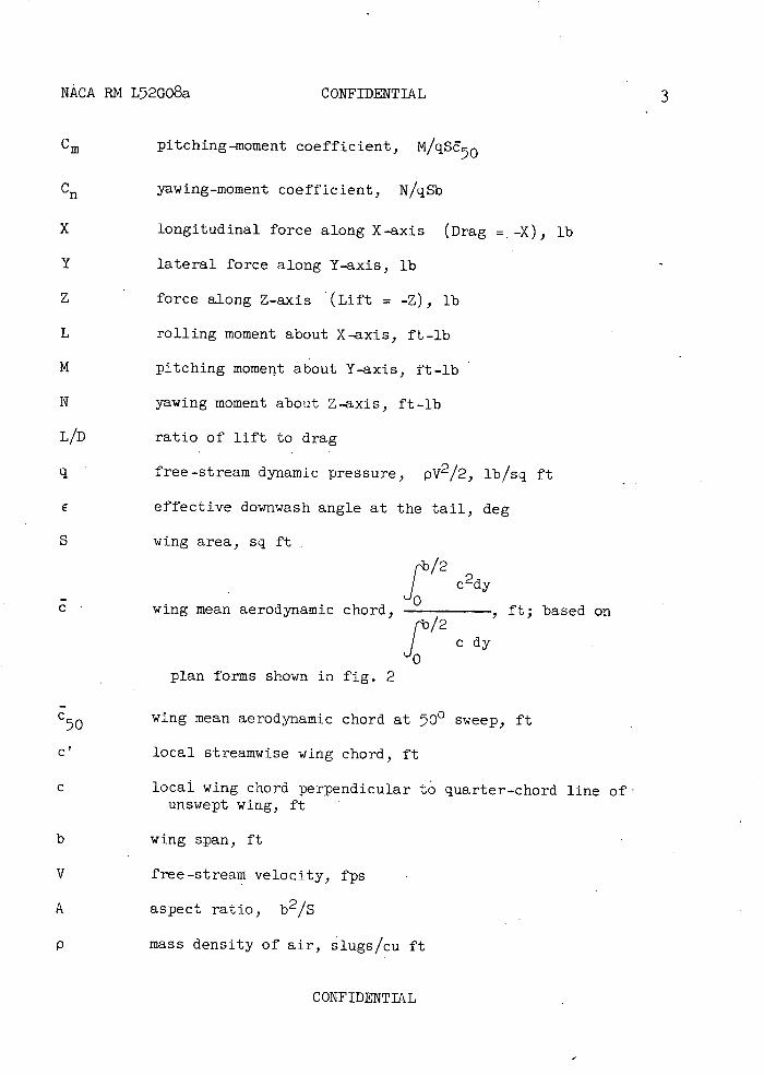
SYMBOLS
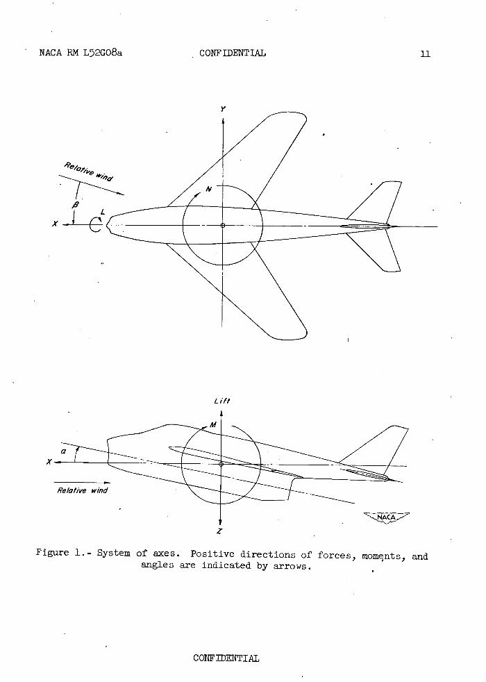
The system of axes employed, together with the positive direction of the forces, moments, and angles, is given in figure 1. The aerody-namic force and moment coefficients are based on the actual wing area and span which vary with sweep angle, but a constant chord, equal to the wing mean aerodynamic chord at 500 sweep, is used for the pitching-moment coefficients. The pitching moments were measured about a fixed fuselage station corresponding to the quarter-chord point of the mean aerodynamic chord of the wing, which was translated so that the quarter-chord point of the mean aerodynamic chord at any sweep angle fell at this same fuse-lage station. (See fig. 2.) The symbols used are defined as follows:
C L lift coefficient, L.ft/qS
C longitudinal-force coefficient, x/qS
CY lateral-force coefficient, Y/qs
C 1 rolling-moment coefficient, L/qsb
CONFIDENTIAL -
NACA P.M L52GO8a CONFIDENTIAL 3
Cm pitching-moment coefficient, M/qSE70
C yawing-moment coefficient, N/qSb
X longitudinal force along X-axis (Drag = . -X), lb
Y lateral force along Y-axis, lb
Z force along Z-axis (Lift = -z), lb
L rolling moment about X-axis, ft-lb
M pitching moment about Y-axis, ft-lb
N yawing moment about Z-axis, ft-lb
L/D ratio of lift to drag
q free-stream dynamic pressure, pV2/2, lb/sq ft
E effective downwash angle at the tail, deg
S wing area, sq ft
J cdy wing mean aerodynamic chord, , ft; based on
[b/2
J cdy plan forms shown in fig. 2
0
c 50 wing mean aerodynamic chord at 700 sweep, ft
CY local streamwise wing chord, ft
c local wing chord perpendicular to quarter-chord line of unswept wing, ft
b wing span, ft
V free-stream velocity, fps
A aspect ratio, b2/S
P mass density of air, slugs/cu ft
CONFIDENTIAL
CONFIDENTIAL NACA RM L52GO8a
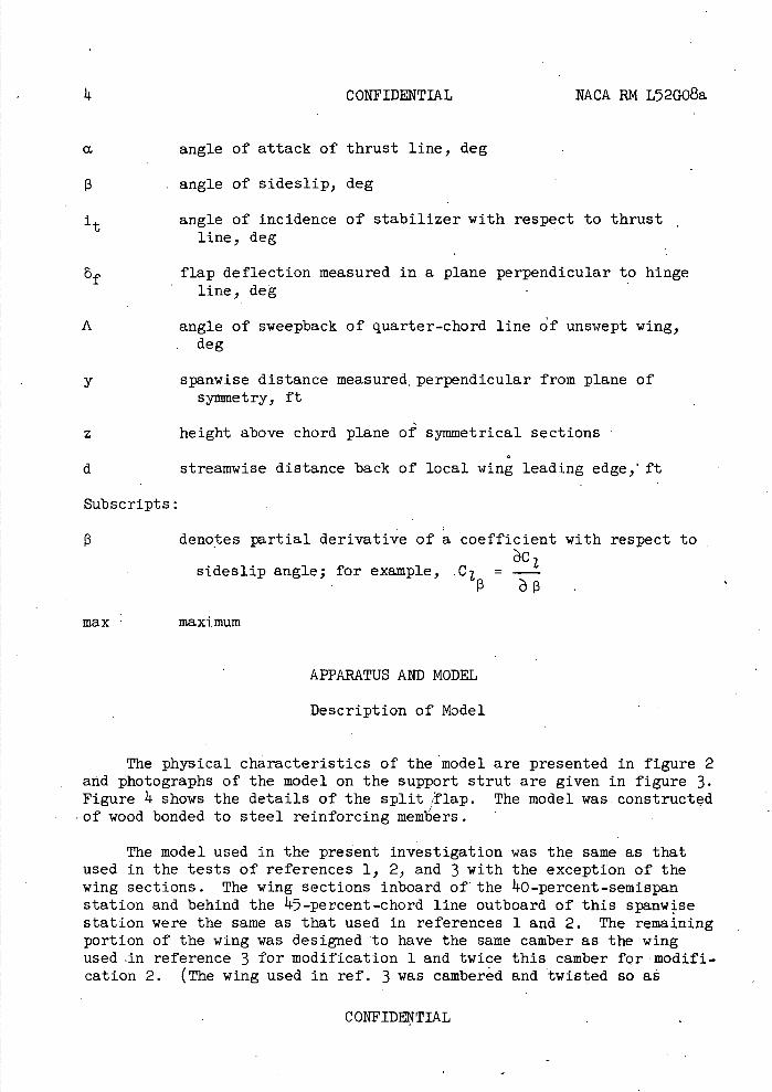
M angle of attack of thrust line, deg
angle of sideslip, deg
it angle of incidence of stabilizer with respect to thrust line, deg
bf flap deflection measured in a plane perpendicular to hinge line, deg
A angle of sweepback of quarter-chord line of unswept wing, deg
y spanwise distance measured , perpendicular from plane of symmetry, ft
z height above chord plane of symmetrical sections
d streamwise distance back of local wing leading edge, ft
Subscripts:
13 denotes partial derivative of a coefficient with respect to
sideslip angle; for example, C 1 = Cl-
max maximum
APPARATUS AND MODEL
Description of Model
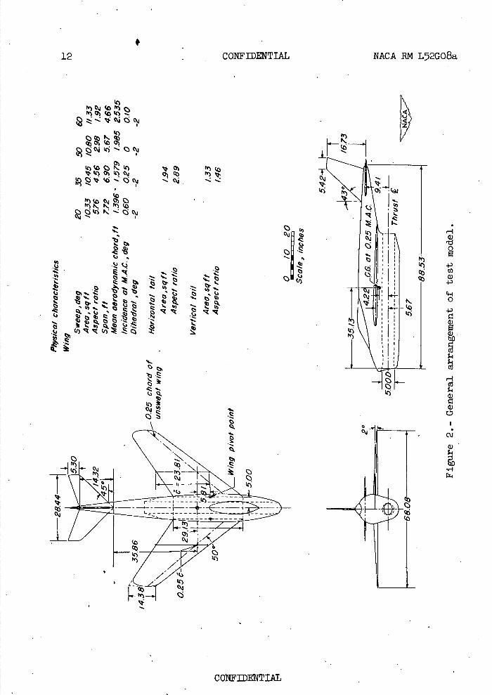
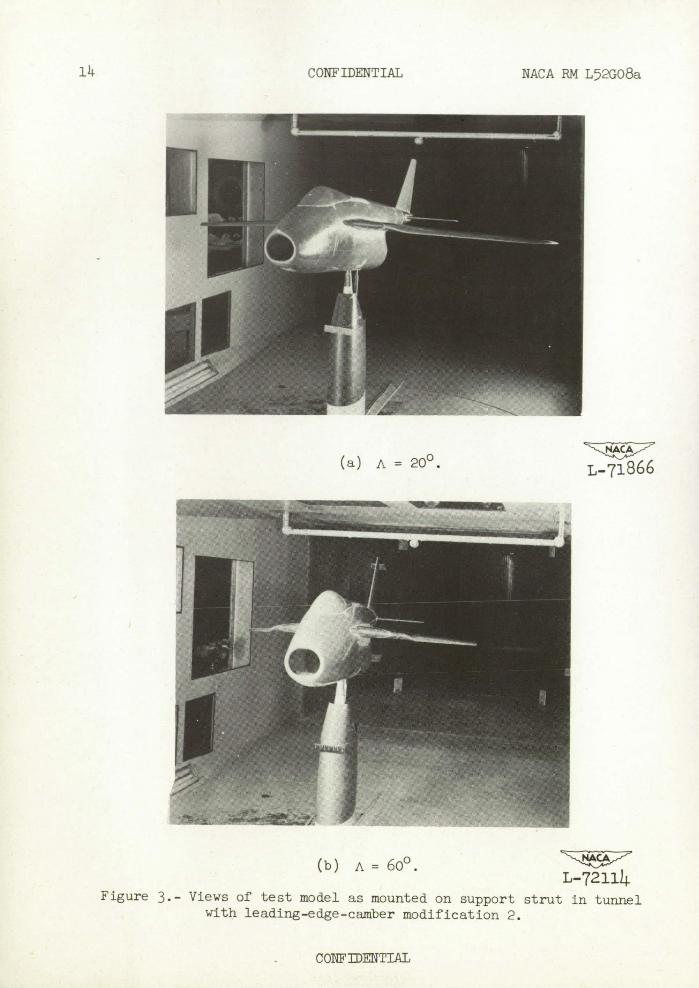
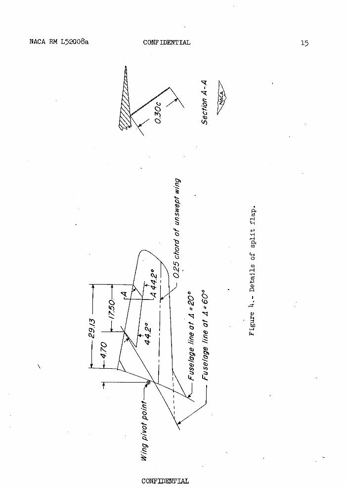
The physical characteristics of the model are presented in figure 2 and photographs of the model on the support strut are given in figure 3. Figure 1 shows the details of the split flap. The model was constructed of wood bonded to steel reinforcing members.
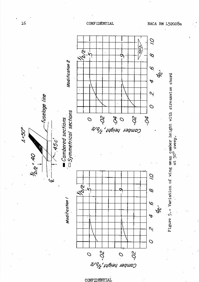
The model used in the present investigation was the same as that used in the tests of references 1, 2, and 3 with the exception of the wing sections. The wing sections inboard of' the O-percent-semispan station and behind the 5-percent-chord line outboard of this spanwise station were the same as that used in references 1 and 2. The remaining portion of the wing was designed to have the same camber as the wing used in reference 3 for modification 1 and twice this camber for modifi-cation 2. (The wing used in ref. 3 was cambered and twisted so as
CONFIDENTIAL .
NACA RM L52GO8a CONFIDENTIAL 5
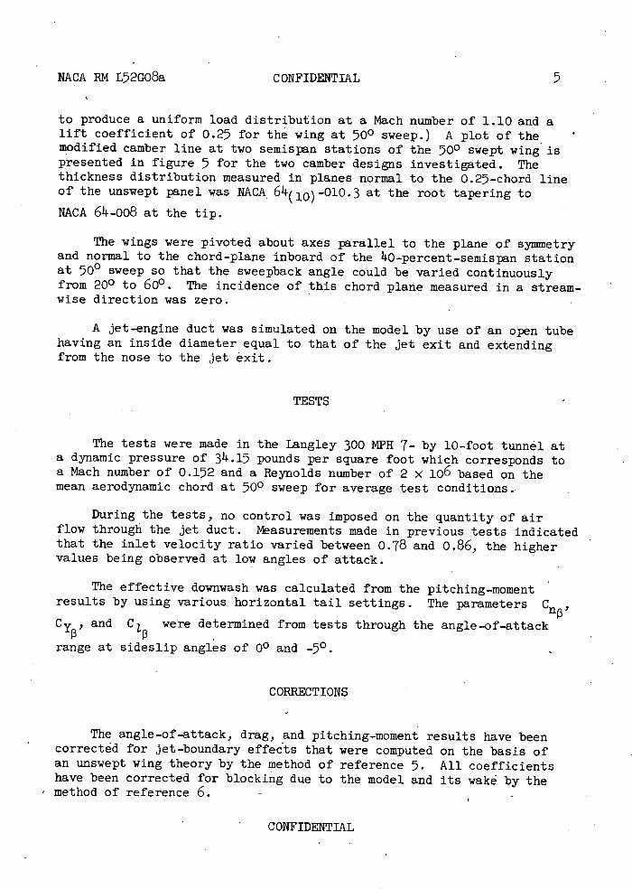
to produce a uniform load distribution at a Mach number of 1.10 and a lift coefficient of 0.25 for the wing at 500 sweep.) A plot of the modified camber line at two semispan stations of the 500 swept wing is presented in figure 5 for the two camber designs investigated. The thickness distribution measured in planes normal to the 0.27-chord line of the unswept panel was NACA 6 -(lo) -01O. 3 at the root tapering to
NACA 64-oo8 at the tip.
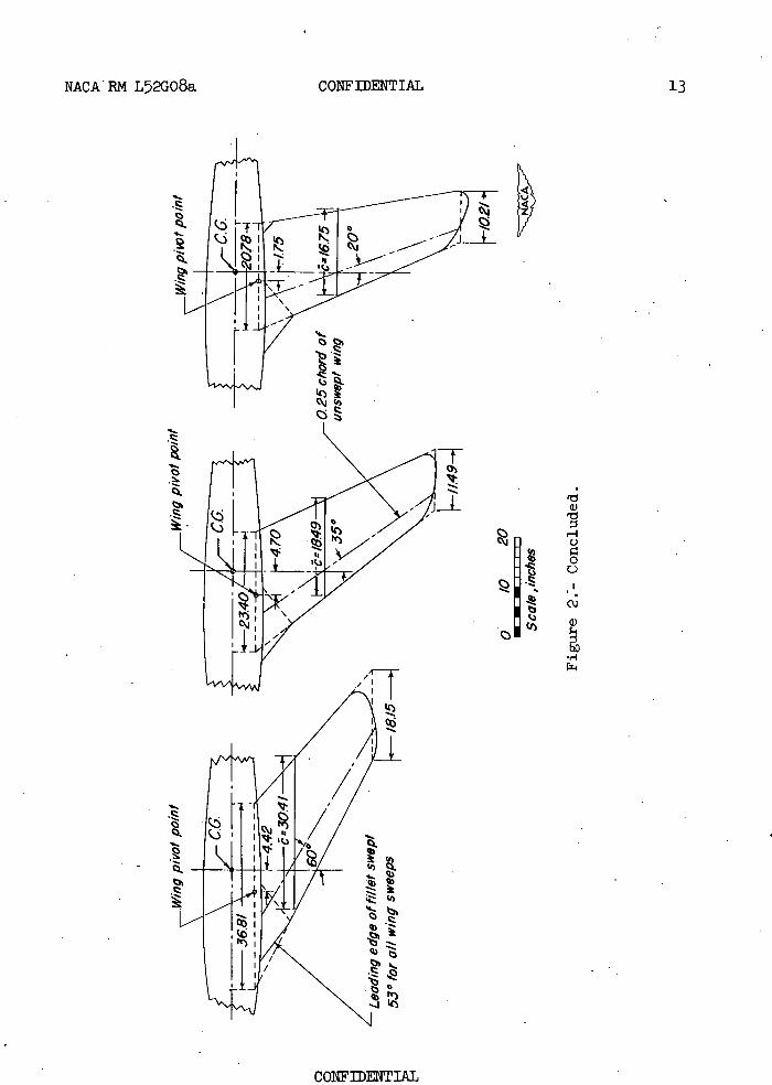
The wings were pivoted about axes parallel to the plane of symmetry and normal to the chord-plane inboard of the 40-percent-semispan station at 500 sweep so that the sweepback angle could be varied continuously from 200 to 600 . The incidence of this chord plane measured in a stream-wise direction was zero.
A jet-engine duct was simulated on the model by use of an open tube having an inside diameter equal to that of the jet exit and extending from the nose to the jet exit.
TESTS
The tests were made in the Langley 300 MPH 7- by 10-foot tunnel at • dynamic pressure of 3.15 pounds per square foot which corresponds to • Mach number of 0.152 and a Reynolds number of 2 x 10 6 based on the mean aerodynamic chord at 500 sweep for average test conditions..
During the tests, no control was imposed on the quantity of air flow through the jet duct. Measurements made in previous tests indicated that the inlet velocity ratio varied between 0.78 and 0.86, the higher values being observed at low angles of attack.
The effective downwash was calculated from the pitching-moment results by using various horizontal tail settings. The parameters
and C 1 were determined from tests through the angle-of-attack
range at sideslip angles of 00 and _50•
CORRECTIONS
The angle-of-attack, drag, and pitching-moment results have been corrected for jet-boundary effects that were computed on the basis of an unswept wing theory by the method of reference 5. All coefficients have been corrected for blocking due to the model and its wake by the method of reference 6. - -
CONFIDENTIAL
6 CONFIDENTIAL NACA RM L52GQ8a
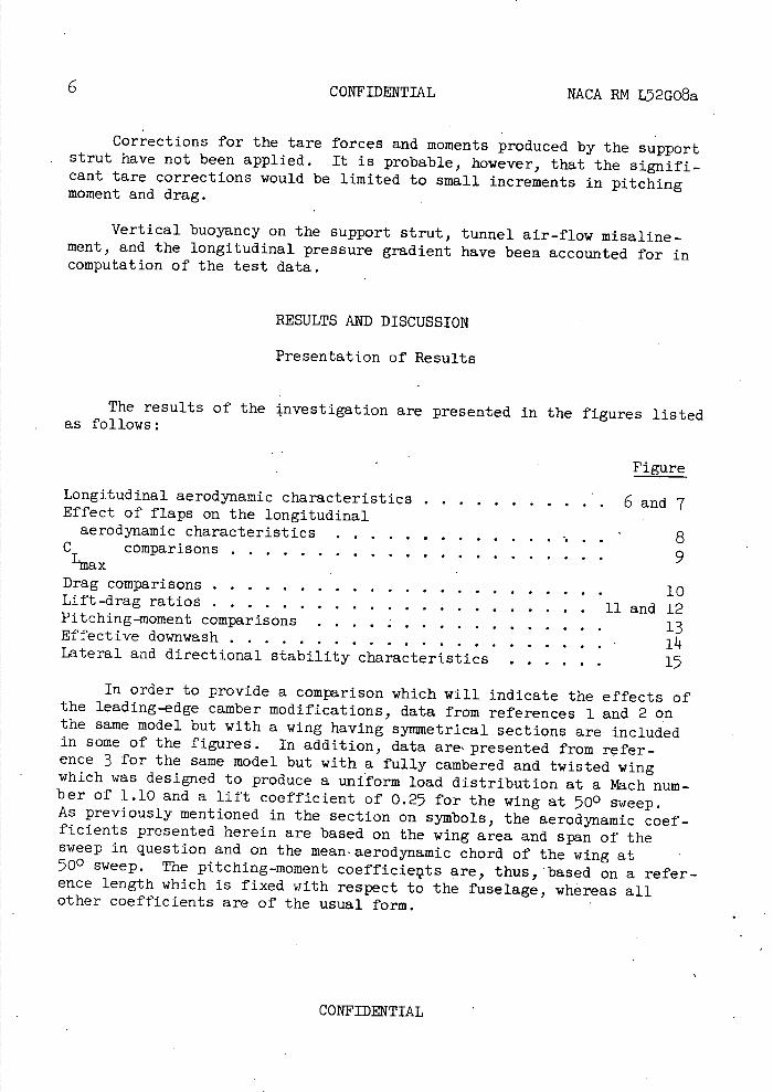
Corrections for the tare forces and moments produced by the support strut have not been applied. It is probable, however, that the signifi-cant tare corrections would be limited to small increments in pitching moment and drag.
Vertical buoyancy on the support strut, tunnel air-flow misaline-ment, and the longitudinal pressure gradient have been accounted for in computation of the test data.
RESULTS AND DISCUSSION
Presentation of Results
The results of the investigation are presented in the figures listed as follows:
Figure
Longitudinal aerodynamic characteristics ............ 6 and 7 Effect of flaps on the longitudinal aerodynamic characteristics .................8
Ccomparisons ......................9 ax
Dragcomparisons ........................ 10 Lift-drag ratios ......................11 and 12 Pitching-moment comparisons ................. 13 Effective downwash ...................... Lateral and directional stability characteristics 17
In order to provide a comparison which will indicate the effects of the leading-edge camber modifications, data from references 1 and 2 on the same model but with a wing having symmetrical sections are included in some of the figures. In addition, data are, presented from refer-ence 3 for the same model but with a fully cambered and twisted wing which was designed to produce a uniform load distribution at a Mach num-ber of 1.10 and a lift coefficient of 0.25 for the wing at 500 sweep. As previously mentioned in the section on symbols, the aerodynamic coef-ficients presented herein are based on the wing area and span of the sweep in question and on the mean-aerodynamic chord of the wing at 500 sweep. The pitching-moment coefficieçits are, thus, 'based on a refer-ence length which is fixed with respect to the fuselage, whereas all other coefficients are of the usual form.
CONFIDENTIAL
NACA RN L52GO8a CONFIDENTIAL 7
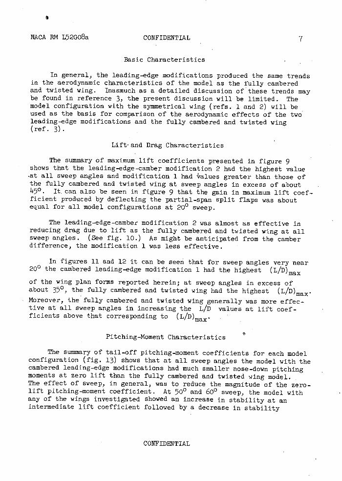
Basic Characteristics
In general, the leading-edge modifications produced the same trends in the aerodynamic characteristics of the model as the fully cambered and twisted wing. Inasmuch as a detailed discussion of these trends may be found in reference 3, the present discussion will be limited. The model configuration with the symmetrical wing (refs. 1 and 2) will be used as the basis for comparison of the aerodynamic effects of the two leading-edge modifications and the fully cambered and twisted wing (ref. 3).
Lift-and Drag Characteristics
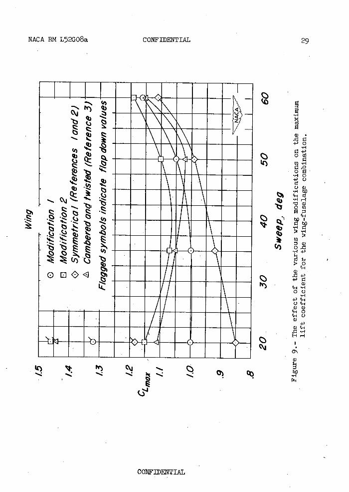
The summary of maximum lift coefficients presented in figure 9 shows that the leading-edge-camber modification 2 had the highest value at all sweep angles and modification 1 had ralues greater than those of the fully cambered and twisted wing at sweep angles in excess of about 450. It. can also be seen in figure 9 that the gain in maximum lift coef-ficient produced by deflecting the partial-span split flaps was about equal for all model configurations at 200 sweep.
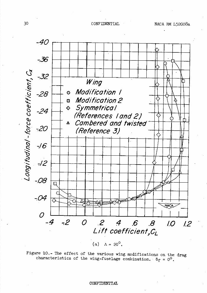
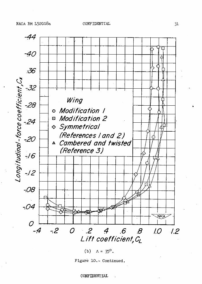
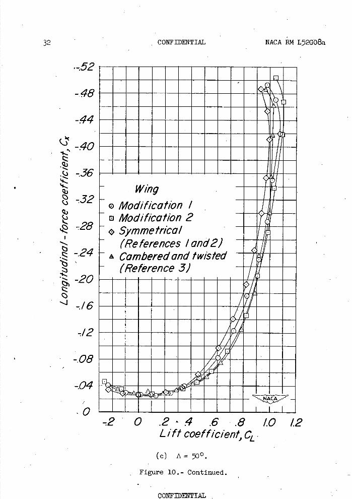
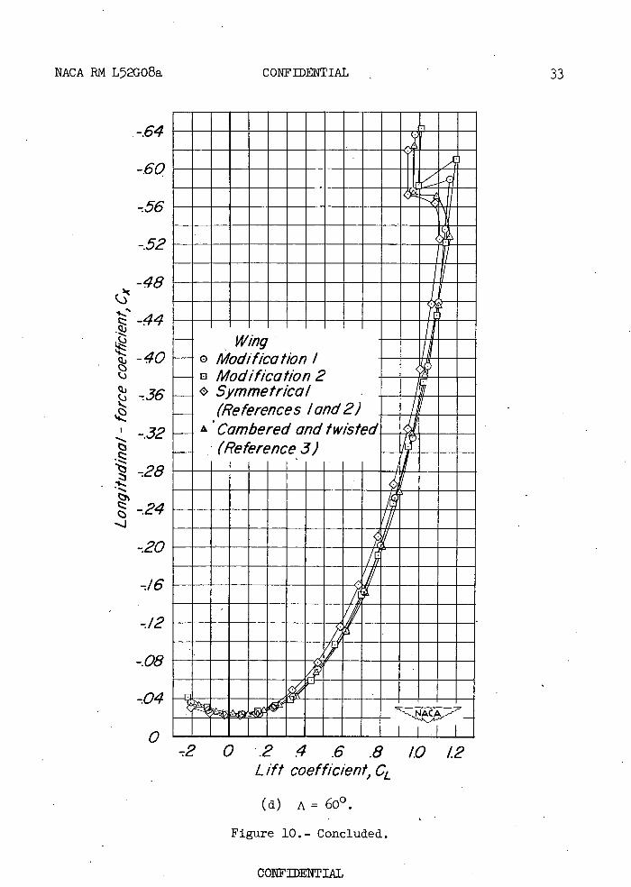
The leading-edge-camber modification 2 was almost as effective in reducing drag due to lift as the fully cambered and twisted wing at all sweep angles. (See fig. 10.) As might be anticipated from the camber difference, the modification 1 was less effective.
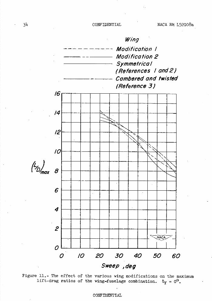
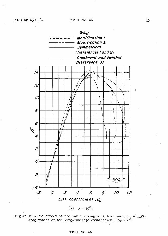
In figures 11 and 12 it can be seen that for sweep angles very near 200 the cambered leading-edge modification 1 had the highest (L/D)max
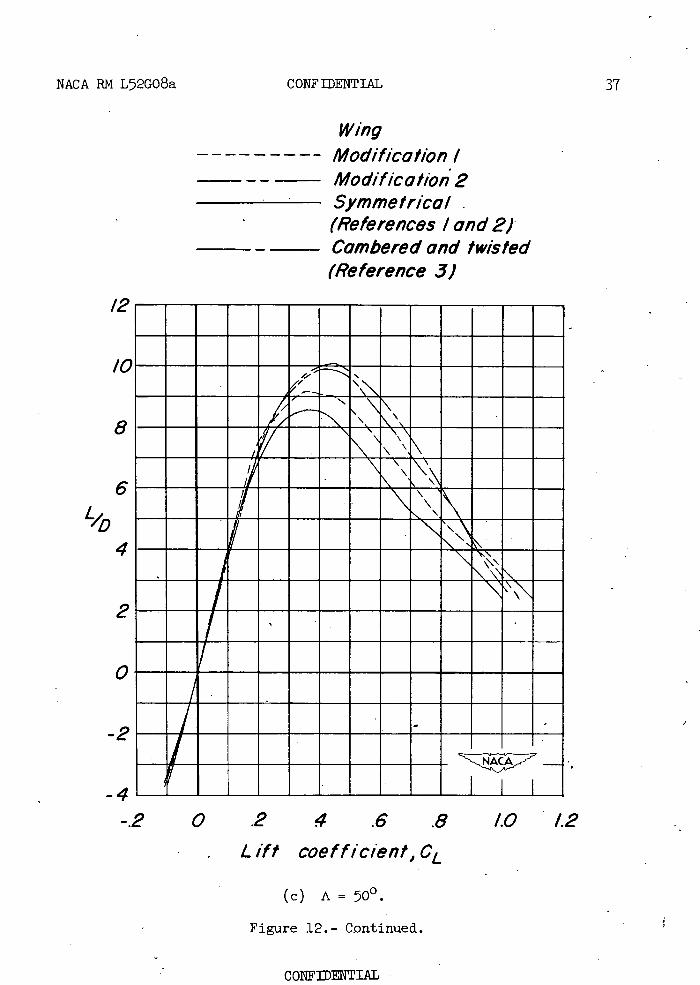
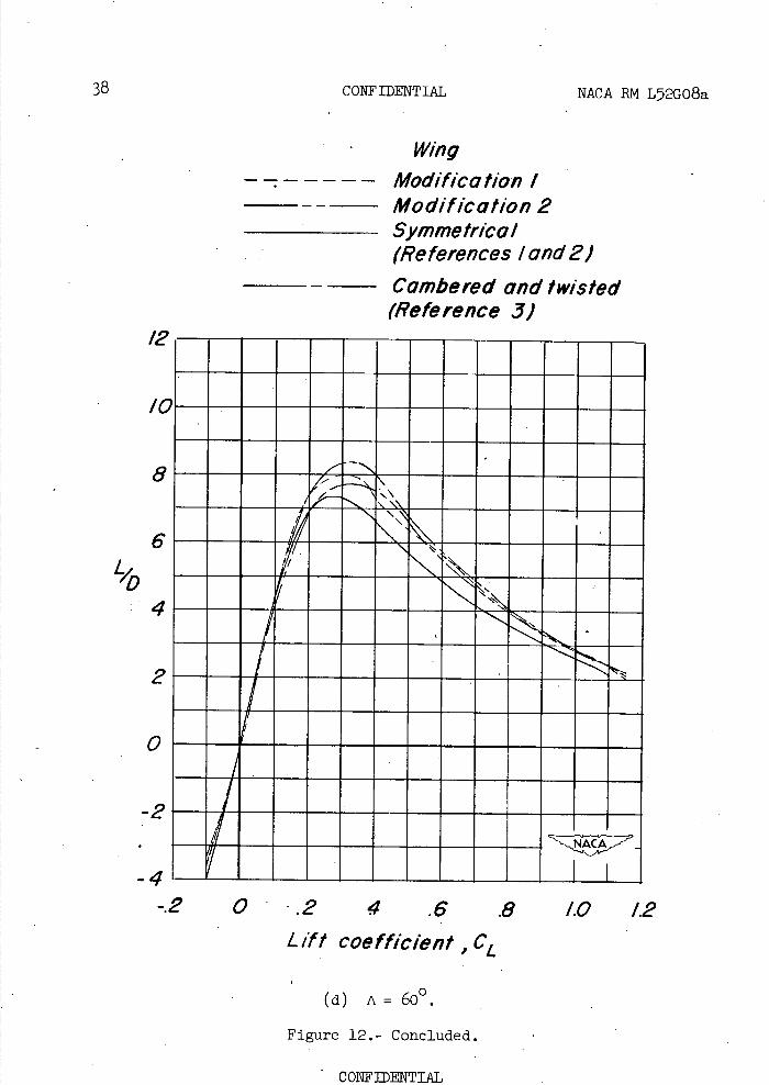
of the wing plan forms reported herein; at sweep angles in excess of about 35, the fully cambered and twisted wing had the highest (L/D)max.
Moreover, the fully cambered and twisted wing generally was more effec-tive at all sweep angles in increasing the L/D values at lift coef-ficients above that corresponding to (L/D)max
Pitching-Moment Characteristics
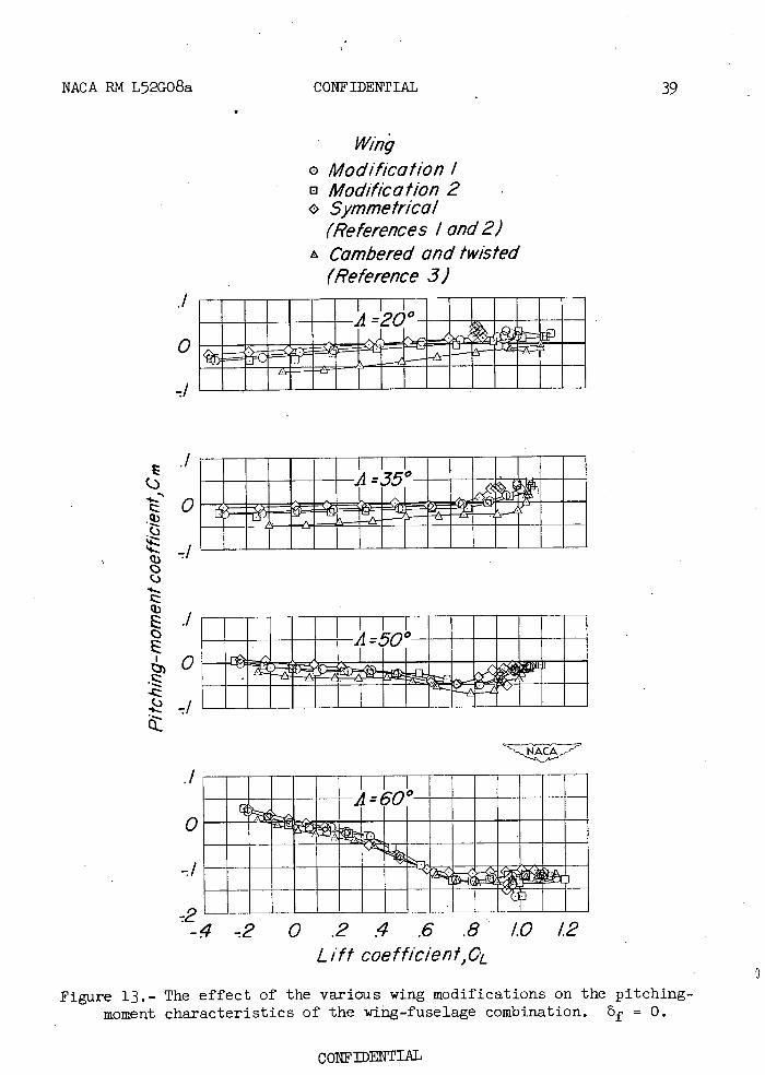
The summary of tail-off pitching-moment coefficients for each model configuration (fig. 13) shows that at all sweep angles the model with the cambered leading-edge modifications had much smaller nose-down pitching moments at zero lift than the fully cambered and twisted wing model. The effect of sweep, in general, was to reduce the magnitude of the zero-lift pitching-moment coefficient. At 500 and 600 sweep, the model with any of the wings investigated showed an increase in stability at an intermediate lift coefficient followed by a decrease in stability
CONFIDENTIAL
8 CONFIDENTIAL NCA RN L52GO8a
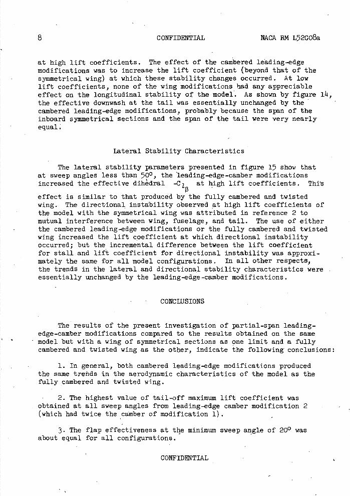
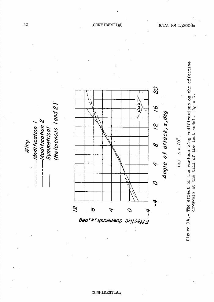
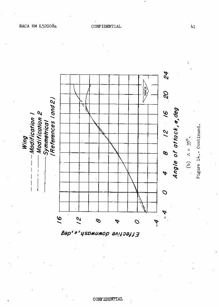
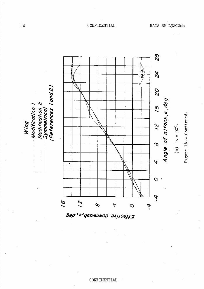
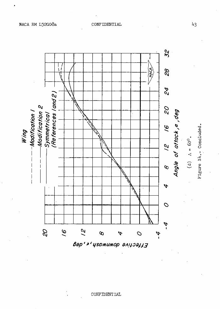
at high lift coefficients. The effect of the cambered leading-edge modifications was to increase the lift coefficient (beyond that of the symmetrical wing) at which these stability changes occurred. At low lift coefficients, none of the wing modifications had any appreciable effect on the longitudinal stability of the model. As shown by figure l), the effective downwash at the tail was essentially unchanged by the cambered leading-edge modifications, probably because the span of the inboard symmetrical sections and the span of the tail were very nearly equal.'
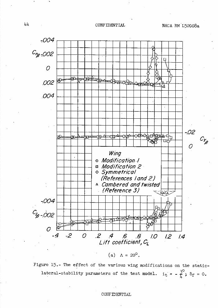
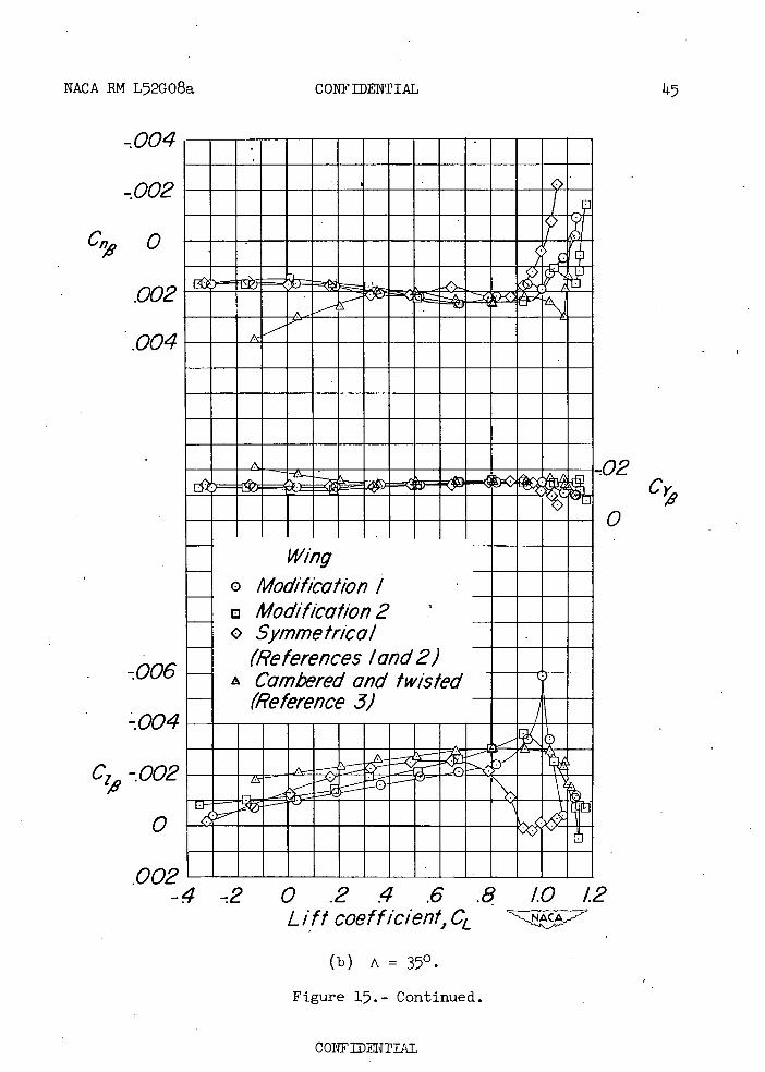
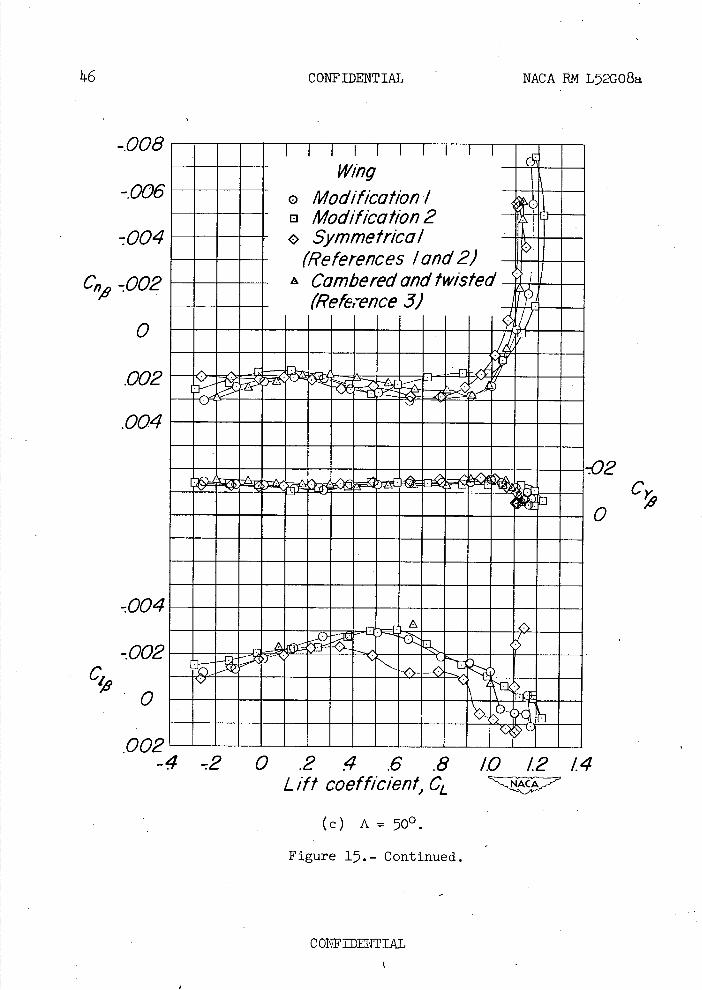
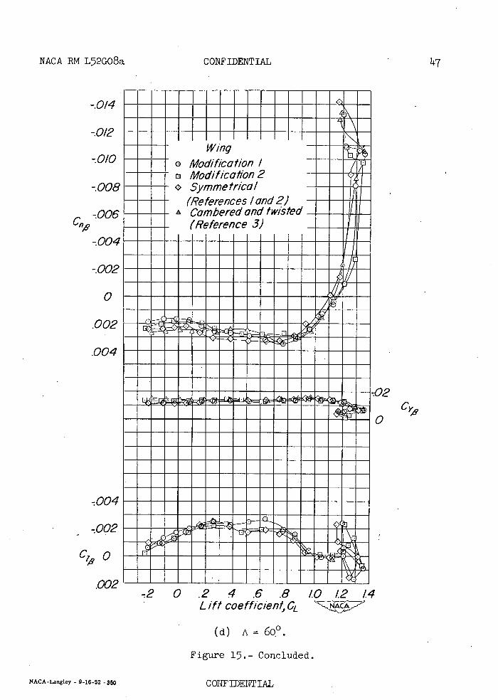
Lateral Stability Characteristics
The lateral stability parameters presented in figure 15 show that at sweep angles less than 500 , the leading-edge-camber modifications increased the effective dihdral -C 1 at high lift coefficients. This
effect is similar to that produced by the fully cambered and twisted wing. The directional instability observed at high lift coefficients of the model with the symmetrical wing was attributed in reference 2 to mutual interference between wing, fuselage, and tail. The use of either the cambered leading-edge modifications or the fully cambered and twisted wing increased the lift coefficient at which directional instability occurred; but the incremental difference between the lift coefficient for stall and lift coefficient for directional instability was approxi-mately the same for all model configurations. In all other respects, the trends in the lateral and directional stability characteristics were essentially unchanged by the leading-edge-camber modifications.
CONCLUSIONS
The results of the present investigation of partial-span leading-edge-camber modifications compared to the results obtained on the same model but with a wing of symmetrical sections as one limit and a fully cambered and twisted wing as the other, indicate the following conclusions:
1. In general, both cambered leading-edge modifications produced the same trends in the aerodynamic characteristics of the model as the fully cambered and twisted wing.
2. The highest value of tail-off maximum lift coefficient was obtained at all sweep angles from leading-edge camber modification 2 (which had twice the camber of modification 1).
3. The flap effectiveness at the minimum sweep angle of 200 was about equal for all configurations.
CONFIDENTIAL
NACA RN L52GO8a CONFIDENTIAL 9
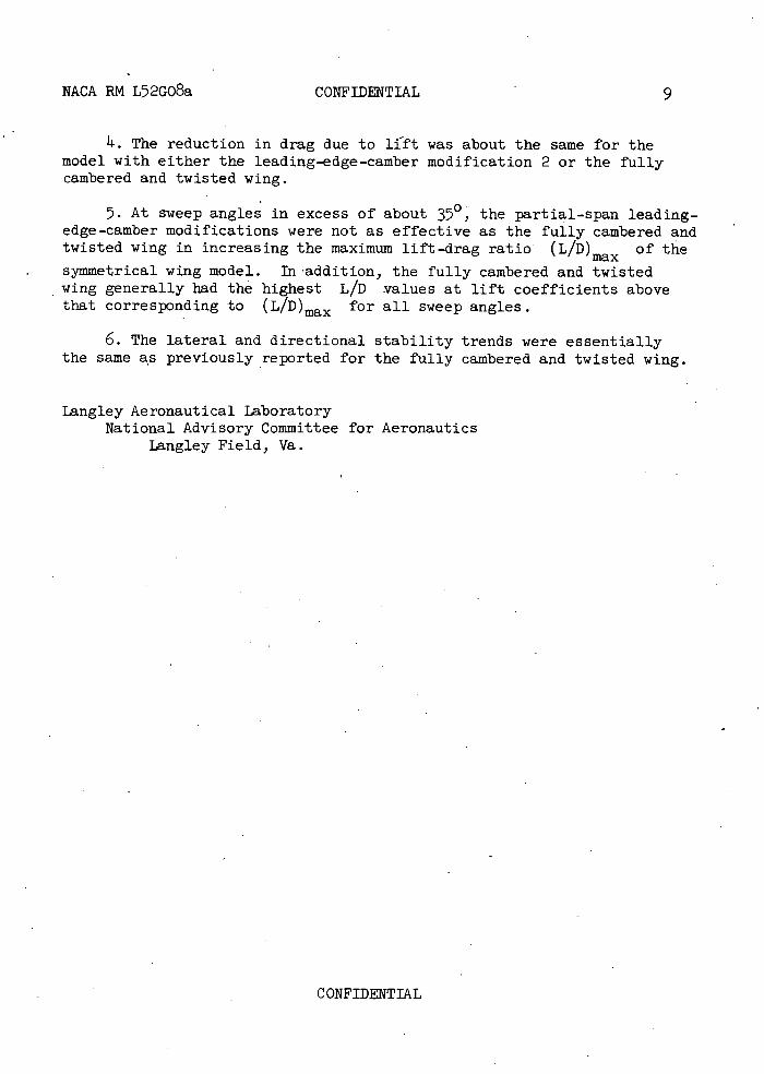
4. The reduction in drag due to lift was about the same for the model with either the leading-edge-camber modification 2 or the fully cambered and twisted wing.
5. At sweep angles in excess of about 350, the partial-span leading-edge-camber modifications were not as effective as the fully cambered and twisted wing in increasing the maximum lift-drag ratio (L/D)max of the
symmetrical wing model. In addition, the fully cambered and twisted wing generally had the highest L/D values at lift coefficients above that corresponding to (L/D)max for all sweep angles.
6. The lateral and directional stability trends were essentially the same as previously reported for the fully cambered and twisted wing.
Langley Aeronautical Laboratory National Advisory Committee for Aeronautics
Langley Field, Va.
CONFIDENTIAL
10 CONFIDENTIAL NACA RN L52GO8a
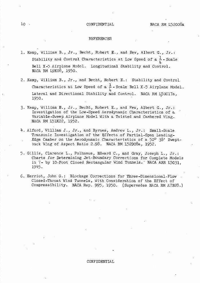
REFERENCES
1. Kemp, William B., Jr., Becht, Robert E., and Few, Albert G., Jr.:
Stability and Control Characteristics at Low Speed of a - Scale
Bell X-5 Airplane Model. Longitudinal Stability and Control. NACA RM L9K08 , 1950.
2. Kemp, William B., Jr., and Becht, Robert E.: Stability and Control
Characteristics at Low Speed of-a -Scale Bell X-5 Airplane Model.
Lateral and Directional Stability and Control. NACA RM L5OCl7a, 1950.
3. Kemp, William B., Jr., Becht, Robert E., and Few, Albert G., Jr.: Investigation of the Low-Speed Aerodynamic Characteristics of a Variable-Sweep Airplane Model With a Twisted and Cambered Wing. NACA RM L51K22, 1952.
1 . Alford, William J., Jr., and Byrnes, Andrew L., Jr.: Small-Scale Transonic Investigation of the Effects of Partial-Span Leading-
- Edge Camber on the Aerodynamic Characteristics of a 500 38' Swept-back Wing of Aspect Ratio 2.98. NACA EM L5 2DO8a , 1952.
5. Gillis, Clarence L., Polhamus, Edward C., and Gray, Joseph L., Jr.: Charts for Determining Jet-Boundary Corrections for Complete Models in 7- by 10-Foot Closed Rectangular Wind Tunnels. - NACA ARR L5G31, 1945.
6. Herriot, John G.: Blockage Corrections for Three-Dimensional-Flow Closed-Throat Wind Tunnels, With Consideration of the Effect of Compressibility. NACA Rep. 995, 1950. (Supersedes NACA RN A7B28.)
CONFIDENTIAL
x
x
NACA RN L52G08a CONFIDENTIAL 11
V
Lift
z
Figure 1.- System of axes. Positive directions of forces, moments ,, and angles are indicated by arrows.
CONFIDENTIAL
frQc
o CQrD
co
'I-
rk
.
•1 Rbull 1: 11 s:n .'J tz
Ic
rn 7
QO
I.)
ri lu
V
LH
rd
U) a)
CH 0
a) E a) to
cd H
a)
(\1
Q
U
12
CONFIDENTIAL
NACA RM L52GO8a
CONFIDENTIAL
NACARN L52GO8a CONFIDENTIAL 13
lu'
to V
h Az
-F
Oi
9
0
a)
r-I C,
0 0
c'J a)
fr-i
CONFIDENTIAL
CONFIDENTIAL NACA RM L72008a
Li I,
(a) A = 20°. - , ___ .....
L-71366
h/(b) A - 600. L-7211t.
Figure 3.-. Views of test model as mounted on support strut in tunnel with leading-edge-camber modification 2.
CONFIDENTIAL
. Iz/
q) (I)
ON
I,tc
0
Cj
0
II Ii
Q) q)
Q q) U) U)
44 cd
H
-p
H P4 0)
c-I 0
U) H •H
-p a)
U)
r-I
\
NACA RM L52GO8a CONFIDENTIAL 17
CONFIDENTIAL
(4) il NNH
Vi h
1•
.,-1
\1
a)
—J4.) r1
4)
bO
a)a)
00
bb r.
C4—'
0
('Ps 0 •H
F a)
'/q4/c9q JêW49
16 CONFIDENTIAL NACA RN L52GQ8a.
mmmomm i•uuuuu MEMO
Cj I Ery
0
a) C')
?/c . 'i,iai/ ieqwo
COTFTI.AL
NACA RM L52GO8a CONFIDENTIAL 17
.Q .1
C)
E
't ,deg
-Si o-
ci
o Horizontal tall off
-43
24I1 '-'-4
I6 -S I:
Q3
Iq
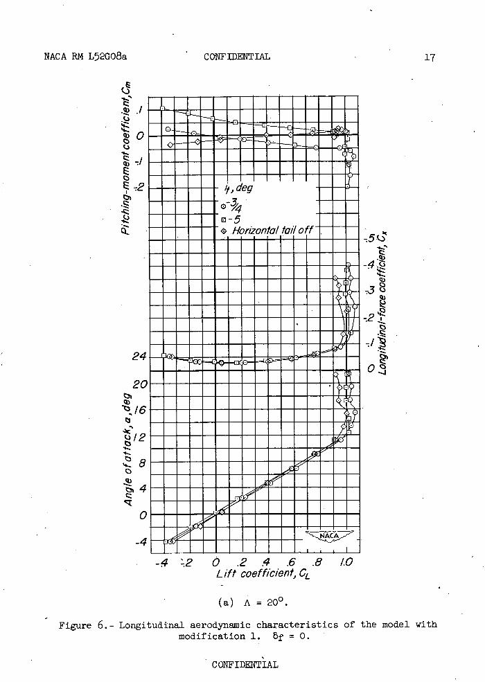
-4 2 0 .2 .4 .6 .8 1.0 Lift coefficient, CL
(a) A=20°.
Figure 6. - Longitudinal aerodynamic characteristics of the model with modification 1. 5f = 0.
C0NFIDIAL
/,, deg
G Hor,onta/ to/I off
24
.4-
73
I
..11 0.
320
fZl
18
CONFIDENTIAL NACA RM L52GO8a
if
q) 0
E
12
4
rsi
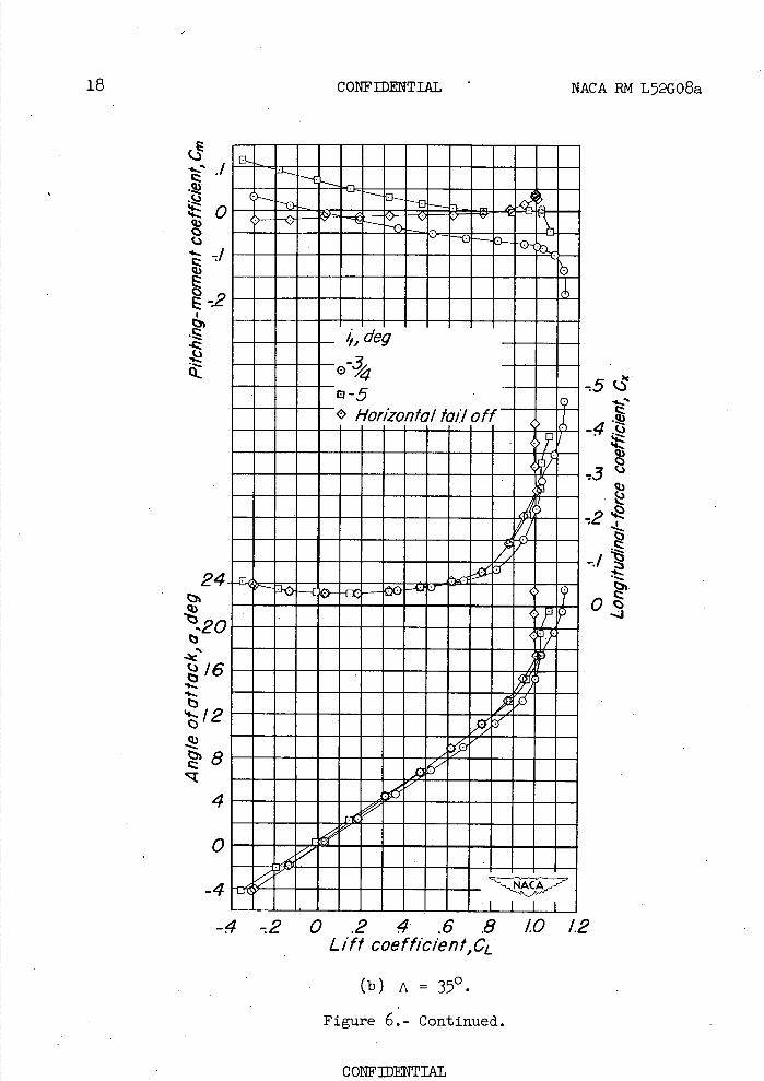
-4-20.24.6.8 10 1.2 Lift coeffic/ent,CL
(b) A = 350.
Figure 6.- Continued.
CONFIDENTIAL
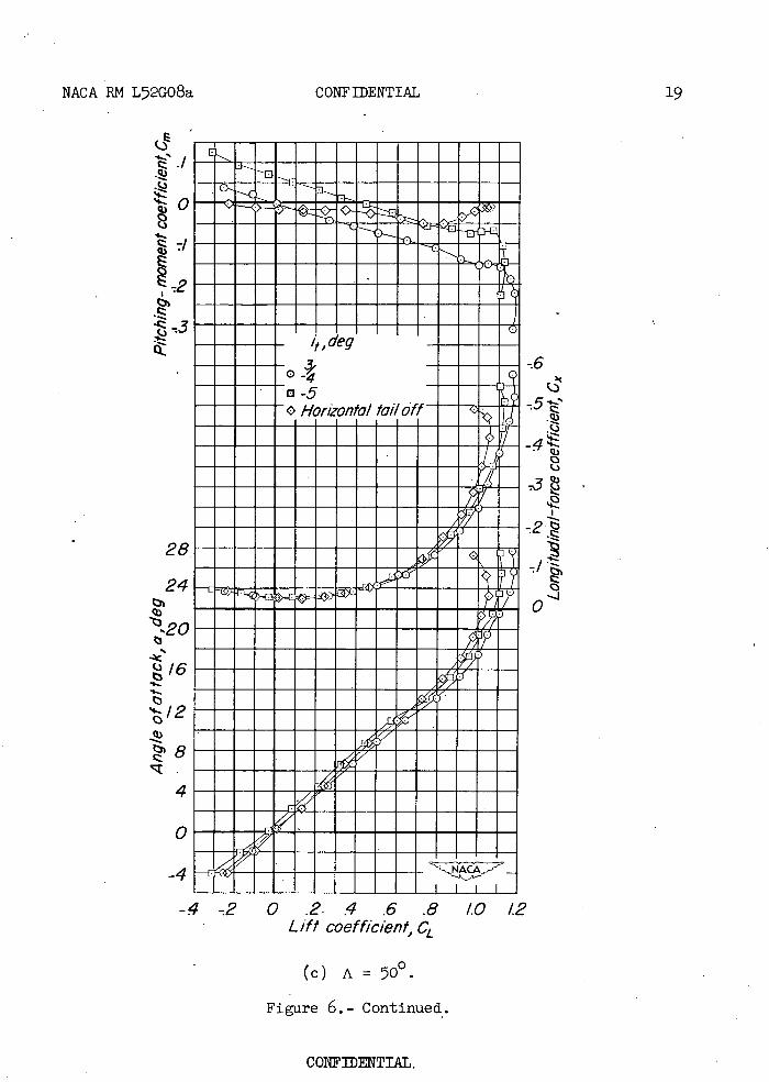
NACA RN L52GO8a CONFIDENTIAL 19
ç)E
S.) I,- Q)
(Ac y
-6
D-5 Horizontal ta//o
-1
28
Q)
24OS-i
-2O
I2
4
ru
inI I I I
-4 -2 0 .2 .4 .6 .8 Lift coefficient, CL
(c) A = 500.
Figure 6.- Continued.
CONFIDENTIAL.
tO /2
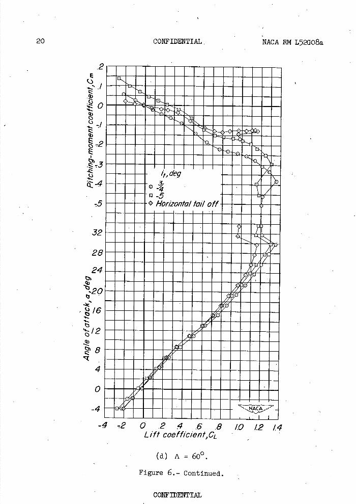
20 CONFIDENTIAL. NACA RN L52G08a
/,,deg
05 G Hor,onta/ tail off
E
q) 0 C)
Q)
E 0 -E
32
28
24 th
320
I6
4
0
-4ill
, .'-, Li I.Lof
Lift coo fficient,GL -
(d) A = 600.
Figure 6.- Continued.
CONFIDENTIAL
NACA RN L52G08a
CONFIDENTIAL
21
1#J
(-7
.Q
Q)- i,,deg
EQ -0 131
D5
• G Horizontal ta/I off
ci
-I
r#i
-4 -2 .0 .2 4 .6 .8 10 1.2 14 Lift coefficient, CL
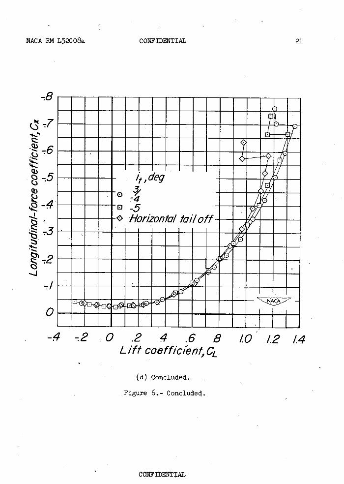
(d) Concluded.
Figure 6.- Concluded.
CONFIDENTIAL
22
CONFIDENTIAL
NACA RN L52G08a
/,ceg
B-5 G Horionta/ ta//off
.4
24 9
20
(3
1.
rz
MI
-4 2 0 .2 4 .6 .8 /0 /2 Lift coefficient, CL
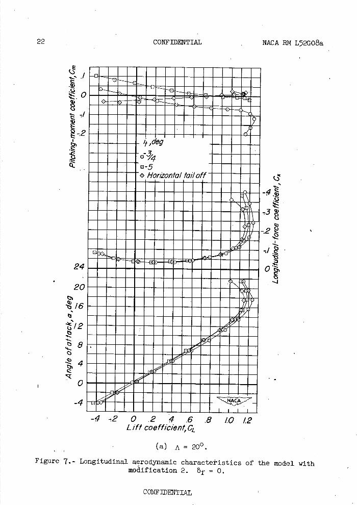
(a) A=20°.
Figure 7.- Longitudinal aerodynamic characteristics of the model with modification 2. bf = 0.
CONF]ENTIAI,
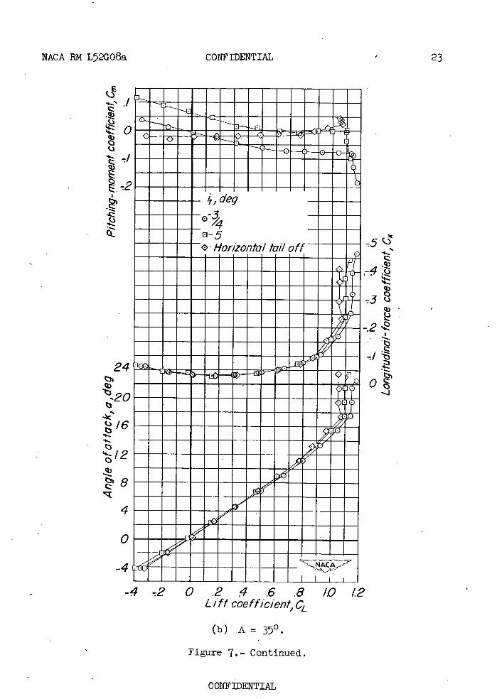
NACA RN L72G08a
CONFIDENTIAL
23
.q)
S.)
q) 0
Ei
S.)
deg
Ili-
• Hor,onta/ tail off -5c
24
1.
q) 0
b20 -4
16
r•si
IMA IA1
-4-2 0.2.4.6.8 1.0 12 L if/ coefficient, CL
(b) A
Figure 7.- Continued.
CONFIDENTIAL
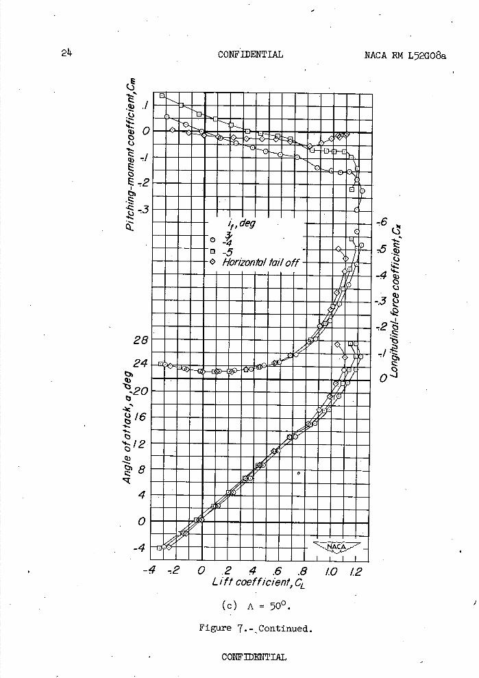
24 CONFIDENTIAL NACA RM L52GO8a
.Q) .1
I::
28 24
!:20 16
I2
4
0
-4
,,,deg o4
Horizontal tall off
I I I
()
-.3
0 0-J
-4 . 2 0 .2 4 .6 .8 10 12 Lift coefficient, CL (c) A = 500.
Figure 7.-Continued.
CONFIDENTIAL
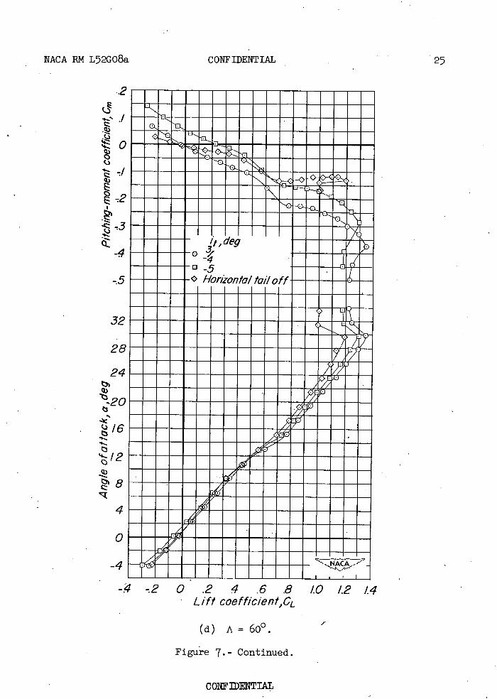
NACA RM L52GO8a CONFIDENTIAL 27
.2
I:
it ,deg -4
D5 -.5
Honionfa/ fat/off
32
28
24
Q3
4
-.4 -2 0.24.6.8 • Lift coefficient,CL
(d) A = 60°.
Figure 7.- Continued.
/0 1.2 /4
CONFIDENTIAL
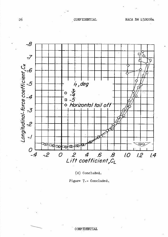
26 CONFIDENTIAL NACA RN L52G08a
-7
., 6
- ci) 0
it., deg
o-5 G Horionta/ ta/I off
-2 0 .2 4 .6 .8 10 12 /4 Lift coefffcient,CL
(d) Concluded.
Figure 7.- Concluded.
CONFIDENTIAL
NACA RN L52G08a CONFIDENTIAL 21
F' (.) 4.4
it, degc) 4.-.'
o-5 Horizontal tail off
4Q.)
4. -/
0. 20
4.
.2.4.6.5 1.0/2/4 L /ft coefficient, CL
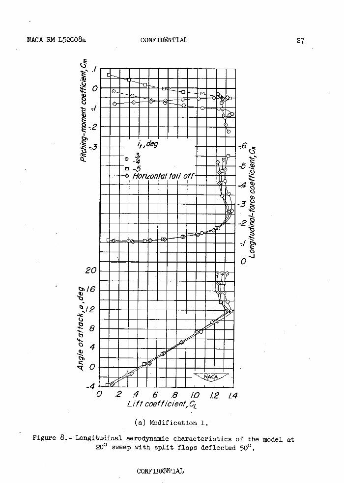
(a) Modification 1.
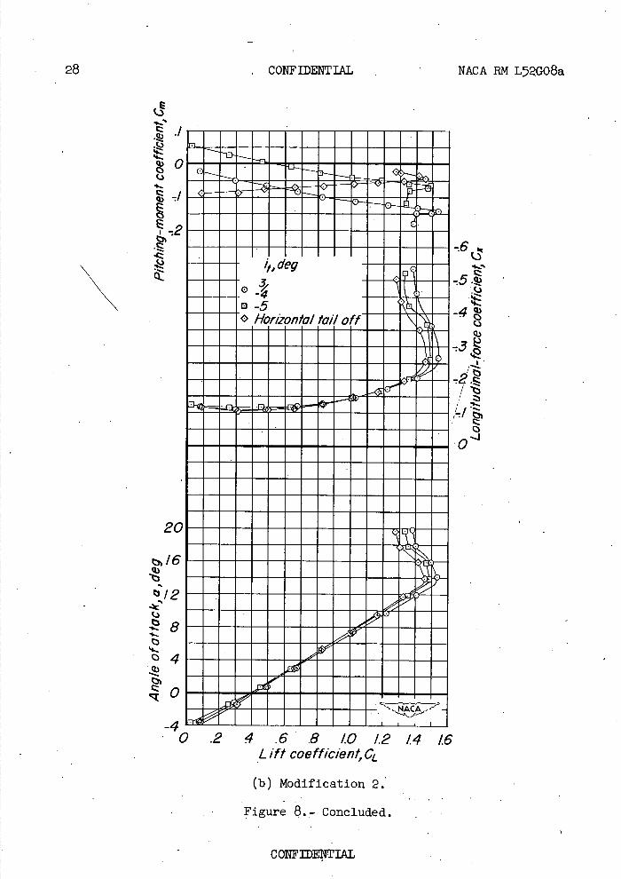
Figure 8.- Longitudinal aerodynamic characteristics of the model at 200 sweep with split flaps deflected 500.
CONFIDENTIAL
I :1
N it, deg
a5 G Horizontal
28 CONFIDENTIAL NACA RN L52G08a
.Q)
20
16
12
_4 L1 I
0 .2
A1 4.6.810 1.21416
Lift coefficient, CL
(b) Modification 2.
Figure 8.- Concluded.
C)
.4-.
.4-
arIj
th
CONFIDENTIAL
IN
-P0
ci
H q)
b
(I)
a)
bD
NACA RN L52G08a CONFIDENTIAL
29
IN.UII MINIMMMININ mml oil' mm MINIM MINIMMUMIN
mm MIM IN MIN m MINIM ME MINIM Ell SIM m I ism ME FA IN MMMMMIMMMM
m Mai's IN IN mm
ME
IC)
CONFIDENTIAL
30
CONFIDENTIAL NACA RN L52G08a
r,J
Me (C
. -28 qJ
-24
Im
MEMO MEMEMEMEME MEMO MEN MEMO ONEji
-
, -'-
- l -- -
• •iuuiu Lill
• III1II • 11,0111 I 111111 • IIIUI NoIIIIIIIIIIiIIji MEN No FM Mium MEMO No•••."•• M MENEM OEMiflU MEN MENI.uvi
0 No •IIIIIII1 1111
ME EMMEMME-4 2 0 .2 4 .6 .8 /0 12
Lift coefffc/ent,GL (a) A 200.
Figure 10.- The effect of the various wing modifications on the drag characteristics of the wing-fuselage combination. 6 = 00.
CONFIDENTIAL
NACA RN L52G08a
CONFIDENTIAL
31
MriJ
a "a
ENNINEEMENEEM mom MENNEENEENEMEWN IN •
MMMMMMII ppMMMMME*I!641.0glim Wing
SymmetricalI,
Cambered an l twJs/edMjAfMjFMM
MIMI M1111112,61M
•0 • 111101 E M 91ISM • •iiiiu I. • MFOREM ••••••••••••,'.• MM1111111111MMMM1011FANAMM MMIN11111111MIMMMUMNIMM MMMMOMMMMMMMPAAMMM MUMMINEEMMOMINIONAuuu WONEWPOMMEEM 1IMMINININE,wo
0 711 al ma
MW !LiiuIllI __ MINNIMEM11
U
0.24.6.81012 Lift coefficient, GL
(b) A = 350
Figure 10.- Continued.
Nfoll
ZZ -32
-28
-24
-2O
-40 I-36
QJ
-28
-20
32
CONFIDENTIAL
NACA RN L52GO8a
•-52
-.48
-44
-/2
-.08
-.04
/
- Wing
o Modification I o Modification 2 o Symmetrical
(References / and2) A Cambered and twisted
- (Reference 3)
Wi
-2 0 .2.4 .6 .8 1.0 12 L 1ff coefficient, CL.
(c) A=500.
Figure 10.- Continued.
CONFIDENTIAL
NACA RN L72G08a
-.64
-.60
-56
-.52
CONFIDENTIAL
-48
-28
-.24
Wing o Modification ' Modification 2 G Symmetrical
(References / and 2) 'Cambered and twisted (Reference 3)
-20
-/6
-/2
-.08
-04
0 I I I
-2 0 .2 4 .6 .8 1.0 12 Lift coefficient, CL
(d) A 60°.
Figure 10.- Concluded.
CONFIDENTIAL
31 CONFIDENTIAL NACA RM L52G08a
Wing - - - - Modification
Modification 2 Symmetrical (References / and 2) Cambered and twisted (Reference 3)
/6
/4
/E
IC
(L-110)max 8
Pj
0 1. I 1 1 I I 1 1 I I I I I 0 /0 20 30 40 50 60
Sweep ,deg Figure 11.- The effect of the various wing modifications on the maximum
lift-drag ratios of the wing-fuselage combination. 5f = 00.
CONFIDENTIAL
NACA RM L52GO8a CONFIDENTIAL 37
Wing Modification / Mod/f/cat/on 2 Symmetrical
(References I and 2) Cambered and twisted (Reference 3)
EMMMMMMM= M MMMMMMMMUMMMMM MMMMMMOMMEMM•• MMMMMMMMMMEMMM MMMMMHMMMMMM UU•VUUlI1lHLIII ••••uii•iiiiii
MMWAFAMMMMRIMMMII MMEMMMMMMMMMM
MMMMMMMMMMMMMM MMMNMMMMMMMMMM1 MMMMMMMMMMMM0M MMEMMMMMMMMMMM MMNMMMMMMMMMMM ............. MENEEMENEENE MHEMENEEMENMEE wi•uu•uu
/d
'F I'
8
6
L194
2
0
-2
-4 -2 0 .2 4 .6 .8 10 1.2
Lift coefficient ,CL
(a) A= 200.
Figure 12.- The effect of the various wing modifications on the lift-
drag ratios of the wing-fuselage combination. 8. = 00.
CONFIDENTIAL

36 CONFIDENTIAL
Wing
- Mod/f/cat/on Modification 2 Sym;etr/ca/
(References / and 2) Cambered and twisted (Reference 3)
NACA RN L52G08a
8
6
0
4
• 2
-2
-4
-2
I
IC
/4
- --- - -
I±III1•EIII I IF J\ I I
-- - v -- -
lilt --\A--
I I
EN
o .2 4 .6 .8. 1.0 1.2
Lift coeff/cient,CL
(b) A 350
Figure 12.- Continued.
CONFIDENTIAL
NACA RM L52GO8a CONFIDENTIAL
Wing Modification Mod/f/cat/on 2 Symmetrical (References /and 2)- Cambered and twisted (Reference 3)
37
/2
/0
8
6 LID
4
EMEMEMMOMEM EMMEMEMMEMEMEM EMEMEMEMEMEMEM U•UUNU•RIU
aauri•umamium urnuu•rnurnrnuuu It•.urnrnuurnu• •uri•uurnrnurnrnrnu urnriurnurnuuurnurnu urniuurnrnrnurnuuuu •wrnuuuuuurnurnrnrn rnraurnuuuurnrn
1.0 1.2
2
0
-2
-.2 0 2 4 .6 .8 Lift coefficient ., CL
(c) A = 500
- Figure 12.- Continued.
CONFIDENTIAL
38
CONFIDENTIAL NACA RM L52G08a
Wing Modification / Modification 2 Syrnme fr/cc / (References / and 2) Cambered and twisted (Reference 3)
8
\ 6
1,4
2
- 0
-2
-4 -.2 0 .2 4 .6 .8 1.0 1.2
Lift coefficient , CL
(d) A=60°.
Figure 12.- Concluded.
- CONFIDENTIAL
NACA RM L52GO8a CONFIDENTIAL 39
wm
o Modification ° Modification 2 G Symmetrical
(References / and 2) Cambered and twisted (Reference 3)
I
IIIIIIIIIII -/ _J....._____J I I I I I I I I I I I I
.1 -
0
-I -
-4 -2 0 .2 4 .6 .8 1.0 12 Lift coefficient,OL
Figure 13.- The effect of the various wing modifications on the pitching-moment characteristics of the wing-fuselage combination. bf = 0.
CONFIDENTIAL
59p 1.0t 4lSDMUMOp 941/39J;3
I'll...
MERRIER: 00,10 ONL^l%IEEE MORMON 0 MEMEMINME 0M001110 0 MENOMINEE MEMMEMEM mommonom MMMMlMlMmM MMMMMIMMM
+
0
U)
0(0 4)
c. OH
CH d H
H 0 rd 0
U) tcOQ)
•H 0
cd cD+)
4-3 Q)
0 4-3 Cd U
EO
c-id
H W
II
I
£ONFLDENTIAL NACA RM L52GO8a
+ U ci)
ci)
(\j
CZ
()
•t.)%- q
I I
- I
CONFIDENTIAL
NACA RN L52GO8a
CONFIDENTIAL
Cs4
flil
I1uH
rH. a)
+
0 - II
< -
q.) •_% ,D
H
)
tio
Es
Cs4co V-
C:)
loap o, °4ISDMUM0p 9A/p9JJ3
11 Ii
COI'1F]ENTIAL
co' -
a)
C''1
-.00 ic'
It
r1 +
0 U
"-I-H
a) 5-
CONFIDENTIAL NACA RN L52GO8a
C..
.-
EEEEEEEI'E1. Qj
'3 'SD4WM0p 9A1/791j3
CONFIDENTIAL
cj
Zt
NACA RM L52GO8a CONFIDENTIAL
a)
• H o () o g
'_o a 0
< I.
H
rd a) ..-
D.
C\j Cj
p'9 '1/sonluMop 9A1/39JJ3
hl
IR
Ii
flF COIDTIAL
114.
-004
c,-002
0
.002
.004
CONFIDENTIAL NACA RN L52GO8a
UPMAC
0 Winq
o Mod/f/cat/on.! o Mod/f/cat/on 2
Symmetrical (References land 2) Cambered and twisted (Reference 3)
-004
.002
-4 -2 0 .2 4 .6 .8 1.0 12 14 L 1ff coefficient, CL
(a) A=20°.
Figure 15.- The effect of the various wing modifications on the static-
lateral-stability parameters of the test model. it = - 0;
e = o.
COflFIDTIAL
NACA RM L52GO8a CONFIDENTIAL 45
-004
-002
CQ
.002
.004
•muuuiuuiuiva
rUU•WiMi R•UIiLI EMOMEMEMEEMEME EMEMEMOMMEMEMEEM uuuuuuuuuu•u••uu •UIURIIII•U••U •uiiuu••iu•uum MEMEMEMOMEMEMEME EMEMEMOMMMEME
1jR
.----..-NONE
•iiu MEN
(References land2) Cdm&ared twisted •iu (Reference •.u.
MEMEMEMEME
•umauuuu•••uu , a•susmumuuummu
C9
-006
-004
C1,6 -002
0
0 .2 4 .6 .8 1.0 12 L if t coefficient, CL
(b) A = 350•
Figure 17.- Continued.
CONFIDENTIAL
-.008
-.006
-:004
Cn, -002
0
.002
.004
NONE MEN i•ii'•uu MEN
NONE MEN NONE ME
m mom MEN iu•u•ii•uuiuuuuiu
mmmmmmmmmmmmmmmmm
mm m OEM mmmmmmmmmmmmmmmmm
mmmmmmmmmmmmmmmmmm •uu•••ui•u•u••uui •u•uu•mu•ii•uuuu•• mmmmmmm ^^Mmmm OEM m an ME ME
ME M ME •iul•u••••Iiuu &mmmmmmmmmmmuuwuu
-004
-002
CO0
We 02010-10
NACA RN L52G08a
2Cr
0 .2 4 .6 .8 1.0 12 14 Lift coefficient, CL
• (c) A=50°.
Figure 15.- Continued.
C ONFIDENTIAL
NACA RM L52008a CONFIDENTIAL
-.0/4
-0/0
-.008
-006 Cflfi
-004
-.002
0
.002
.004
- -002
C7 0
r,rr
CYfi
-2 0 .2 4 .6 .8 10 12 14 Lift coefficient, CL
(d) A = 6o°.
Figure 15.- Concluded.
NACA-Langley - 9-16-2 -350 coIFDDENTIAL

SEC U R I 1 'r' I NJ F () P NA ,A1 I CD N.J
::