Embed Size (px)
Citation preview

NA-series HMI Programmable Terminal
Practices Guide Questions & Answers On Page Editing
NA5-15W□□□□
NA5-12W□□□□
NA5-9W□□□□
NA5-7W□□□□
V422-E1-01

2
■ Introduction This guide provides reference information on editing pages of the NA. It does not provide safety
information.
Be sure to obtain the NA-series Programmable Terminal User's Manuals, read and understand the safety
points and other information required for use, and test sufficiently before actually using the equipment.
(1) All rights reserved. No part of this publication may be reproduced, stored in a retrieval system, or
transmitted, in any form, or by any means, mechanical, electronic, photocopying, recording, or otherwise, without the prior written permission of OMRON.
(2) No patent liability is assumed with respect to the use of the information contained herein. Moreover, because OMRON is constantly striving to improve its high-quality products, the information contained in this manual is subject to change without notice. Every precaution has been taken in the preparation of this manual. Nevertheless, OMRON assumes no responsibility for errors or omissions. Neither is any liability assumed for damages resulting from the use of the information contained in this publication.
(3) Trademarks • Sysmac and SYSMAC are trademarks or registered trademarks of OMRON Corporation in Japan and other countries for OMRON factory automation products. • Windows, Visual Basic, and Excel are either registered trademarks or trademarks of Microsoft Corporation in the United States, Japan, and other countries. • Other company names and product names in this document are the trademarks or registered trademarks of their respective companies. • Microsoft product screen shots reprinted with permission from Microsoft Corporation. • The product pictures and drawings contained in this document are the graphical images, which may be different from the actual articles.

3
Terms and Conditions Agreement
Warranty, Limitations of Liability
Warranties
Exclusive Warranty
Omron’s exclusive warranty is that the Products will be free from defects in materials and
workmanship for a period of twelve months from the date of sale by Omron (or such other period
expressed in writing by Omron). Omron disclaims all other warranties, express or implied.
Limitations
OMRON MAKES NO WARRANTY OR REPRESENTATION, EXPRESS OR IMPLIED,
ABOUT NON-INFRINGEMENT, MERCHANTABILITY OR FITNESS FOR A PARTICULAR
PURPOSE OF THE PRODUCTS. BUYER ACKNOWLEDGES THAT IT ALONE HAS
DETERMINED THAT THE PRODUCTS WILL SUITABLY MEET THE REQUIREMENTS OF
THEIR INTENDED USE.
Omron further disclaims all warranties and responsibility of any type for claims or expenses
based on infringement by the Products or otherwise of any intellectual property right.
Buyer Remedy
Omron’s sole obligation hereunder shall be, at Omron’s election, to (i) replace (in the form
originally shipped with Buyer responsible for labor charges for removal or replacement
thereof) the non-complying Product, (ii) repair the non-complying Product, or (iii) repay or
credit Buyer an amount equal to the purchase price of the non-complying Product; provided
that in no event shall Omron be responsible for warranty, repair, indemnity or any other
claims or expenses regarding the Products unless Omron’s analysis confirms that the
Products were properly handled, stored, installed and maintained and not subject to
contamination, abuse, misuse or inappropriate modification. Return of any Products by
Buyer must be approved in writing by Omron before shipment. Omron Companies shall not
be liable for the suitability or unsuitability or the results from the use of Products in
combination with any electrical or electronic components, circuits, system assemblies or any
other materials or substances or environments. Any advice, recommendations or
information given orally or in writing, are not to be construed as an amendment or addition to
the above warranty.
See http://www.omron.com/global/ or contact your Omron representative for published
information.
Limitation on Liability; Etc
OMRON COMPANIES SHALL NOT BE LIABLE FOR SPECIAL, INDIRECT, INCIDENTAL,
OR CONSEQUENTIAL DAMAGES, LOSS OF PROFITS OR PRODUCTION OR
COMMERCIAL LOSS IN ANY WAY CONNECTED WITH THE PRODUCTS, WHETHER
SUCH CLAIM IS BASED IN CONTRACT, WARRANTY, NEGLIGENCE OR STRICT
LIABILITY.
Further, in no event shall liability of Omron Companies exceed the individual price of the
Product on which liability is asserted.
4
Application Considerations
Suitability of Use
Omron Companies shall not be responsible for conformity with any standards, codes or
regulations which apply to the combination of the Product in the Buyer’s application or use
of the Product. At Buyer’s request, Omron will provide applicable third party certification
documents identifying ratings and limitations of use which apply to the Product. This
information by itself is not sufficient for a complete determination of the suitability of the
Product in combination with the end product, machine, system, or other application or use.
Buyer shall be solely responsible for determining appropriateness of the particular Product
with respect to Buyer’s application, product or system. Buyer shall take application
responsibility in all cases.
NEVER USE THE PRODUCT FOR AN APPLICATION INVOLVING SERIOUS RISK TO
LIFE OR PROPERTY WITHOUT ENSURING THAT THE SYSTEM AS A WHOLE HAS
BEEN DESIGNED TO ADDRESS THE RISKS, AND THAT THE OMRON PRODUCT(S) IS
PROPERLY RATED AND INSTALLED FOR THE INTENDED USE WITHIN THE OVERALL
EQUIPMENT OR SYSTEM.
Programmable Products
Omron Companies shall not be responsible for the user’s programming of a programmable
Product, or any consequence thereof.
Disclaimers
Performance Data
Data presented in Omron Company websites, catalogs and other materials is provided as a
guide for the user in determining suitability and does not constitute a warranty. It may
represent the result of Omron’s test conditions, and the user must correlate it to actual
application requirements. Actual performance is subject to the Omron’s Warranty and
Limitations of Liability.
Change in Specifications
Product specifications and accessories may be changed at any time based on
improvements and other reasons. It is our practice to change part numbers when published
ratings or features are changed, or when significant construction changes are made.
However, some specifications of the Product may be changed without any notice. When in
doubt, special part numbers may be assigned to fix or establish key specifications for your
application. Please consult with your Omron’s representative at any time to confirm actual
specifications of purchased Product.
Errors and Omissions
Information presented by Omron Companies has been checked and is believed to be
accurate; however, no responsibility is assumed for clerical, typographical or proofreading
errors or omissions.

5
Contents
Terms and Conditions Agreement ........................................................................ 3
Warranty, Limitations of Liability ............................................................................................. 3 Application Considerations ..................................................................................................... 4 Disclaimers ............................................................................................................................. 4
Related Manuals ..................................................................................................... 6
1 Introduction .................................................................................................... 7
1-1 List of Questions and Answers ................................................................................. 7
2 Questions and Answers ................................................................................ 9
2-1 System Settings ....................................................................................................... 9 2-2 Functions Common to Objects ............................................................................... 11 2-3 Functions Unique to Each Object ........................................................................... 15 2-4 Others ..................................................................................................................... 33
3 Revision History ........................................................................................... 47
6
Related Manuals
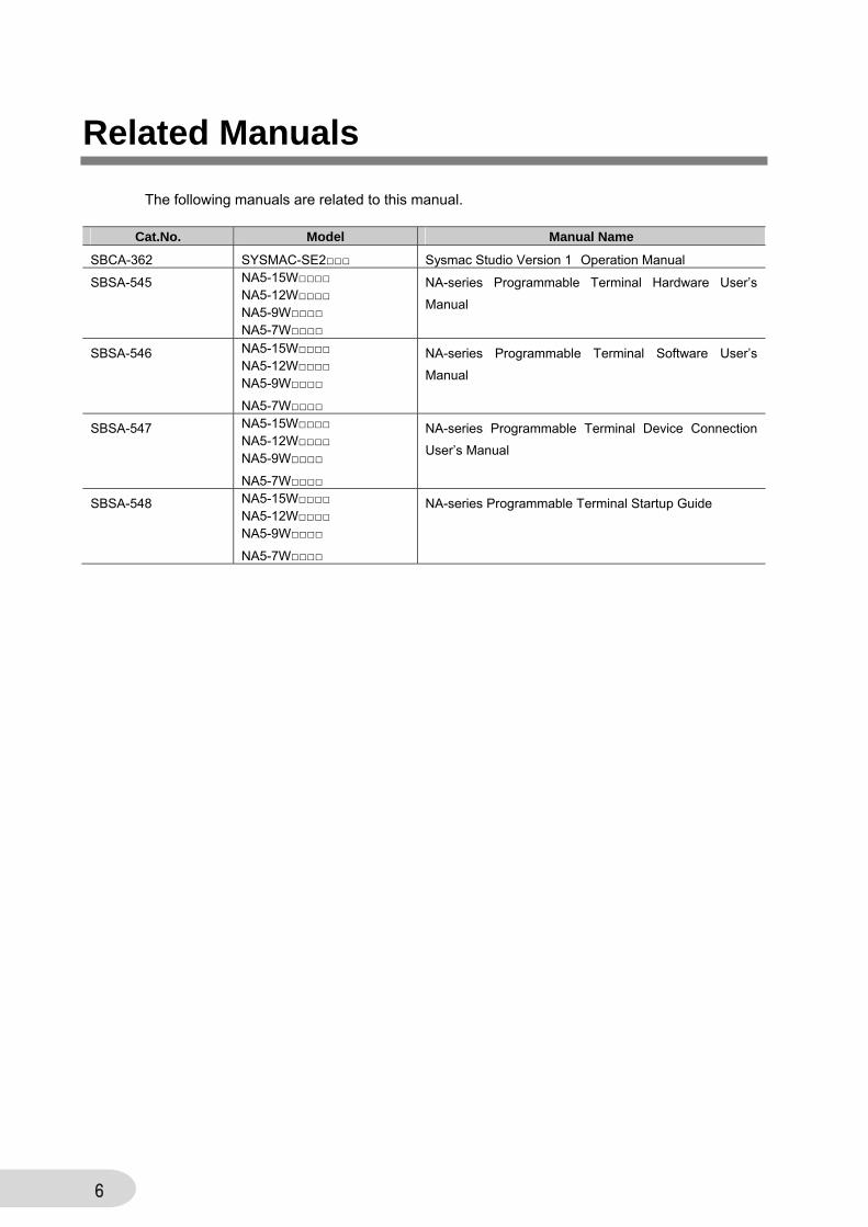
The following manuals are related to this manual.
Cat.No. Model Manual Name
SBCA-362 SYSMAC-SE2□□□ Sysmac Studio Version 1 Operation Manual
SBSA-545 NA5-15W□□□□ NA5-12W□□□□ NA5-9W□□□□ NA5-7W□□□□
NA-series Programmable Terminal Hardware User’s
Manual
SBSA-546 NA5-15W□□□□ NA5-12W□□□□ NA5-9W□□□□
NA5-7W□□□□
NA-series Programmable Terminal Software User’s
Manual
SBSA-547 NA5-15W□□□□ NA5-12W□□□□ NA5-9W□□□□
NA5-7W□□□□
NA-series Programmable Terminal Device Connection
User’s Manual
SBSA-548 NA5-15W□□□□ NA5-12W□□□□ NA5-9W□□□□
NA5-7W□□□□
NA-series Programmable Terminal Startup Guide
7
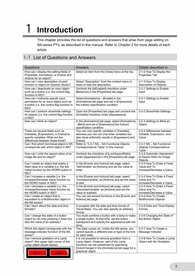
1 Introduction This chapter provides the list of questions and answers that arise from page editing on
NA-series PTs, as described in this manual. Refer to Chapter 2 for more details of each
article.
1-1 List of Questions and Answers Questions Answers Details described in: How can I display the setting fields of Properties, Animations, or Events and Actions for an object?
Select an item from the [View] menu at the top. 2-1-2 How To Display the Properties Tab
How can I view description of each function or object on Sysmac Studio?
Select “Description” from the context menu to show or hide the description.
2-1-3 How To Display Description of Objects
How can I deactivate an input object such as a button (i.e. the control flag function in NS)?
Uncheck the [IsEnabled] checkbox under [Behavior] in the [Properties] tab page.
2-2-1 Settings to Enable Input
How can I indirectly specify input permission for an input object such as a button (i.e. the control flag function in NS)?
Select [Animations] – [Enable] in the [Animations] tab page and set in [Expression] the indirect specification condition.
2-2-1 Settings to Enable Input
How can I perform show/hide settings for objects (i.e. the control flag function in NS)?
Open the [Properties] tab page and uncheck the [IsVisible] checkbox under [Appearance].
2-2-2 Show/Hide Settings
How can I blink an object? In the [Animations] tab page, select [Animations] - [Blink] and set in [Expression] the indirect specification condition.
2-2-3 Settings to Blink an Object
There are several fields such as [Variable], [Expression], or [Value] to specify variables. What are the differences between these three?
You can only specify variables in [Variable], whereas you can not only enter variables but also show arithmetic results in [Expression] and [Value].
2-2-4 Differences between Variable, Expression, and Value
Can I find which functional object in NS corresponds with which object in NA?
Refer to “2-3-1 NS – NA Functional Objects Correspondence Table” in this manual.
2-3-1 NS – NA Functional Objects Correspondence Table
How can I unify the aspect ratios of an image file and an object?
Uncheck the checkbox of [LockAspectRatio] under [Appearance] in the [Properties] tab page.
2-3-2 Automatic Adjustment of Aspect Ratio for Image Objects
Can I create an object that enters a fixed value to a variable (i.e. the Set Value function by the WORD button in NS)?
In the [Events and Actions] tab page, select “SetVariable” as [Actions] and set the value to enter.
2-3-3 How To Enter a Fixed Value and To Increase/Decrease a Value
Can I increase a variable (i.e. the Increase/Decrease Value function by the WORD button in NS)?
In the [Events and Actions] tab page, select “IncreaseVariable” as [Actions] and set the value to add.
2-3-3 How To Enter a Fixed Value and To Increase/Decrease a Value
Can I decrease a variable (i.e. the Increase/Decrease Value function by the WORD button in NS)?
In the [Events and Actions] tab page, select “DecreaseVariable” as [Actions] and set the value to subtract.
2-3-3 How To Enter a Fixed Value and To Increase/Decrease a Value
Can I create an object that is equivalent to a Multifunction object in the NS series?
You can set several functions in the [Events and Actions] tab page.
2-3-4 How To Create Multifunction Objects
Can I learn about the date and time formats?
It complies with the date and time format of Visual Basic. You can also specify an arbitrary format.
2-3-5 Date and Time Display Format
Can I change the state of a button object by not only pressing it down but also the value of an address?
You must combine a button with a lamp to make a single button. At that time, set the button transparent and specify the appearance with the lamp.
2-3-6 Changing the State of the Button Object
Which NA object corresponds with the message indicator function of the NS series?
The Data Lamps do. Unlike the NS-series, you cannot specify a different size or type of the font for each state.
2-3-7 How To Create a Message Indicator
Can I remove gradation of a Lamp object? (the upper right corner of the Lamp object shown below)
It is not possible to remove gradation from a Lamp object. However, part of the Lamp functions can be substituted by specifying [ColorChange] in the [Animations] tab page for a graphical object.
2-3-8 How To Create a Lamp Object with No Gradation
8
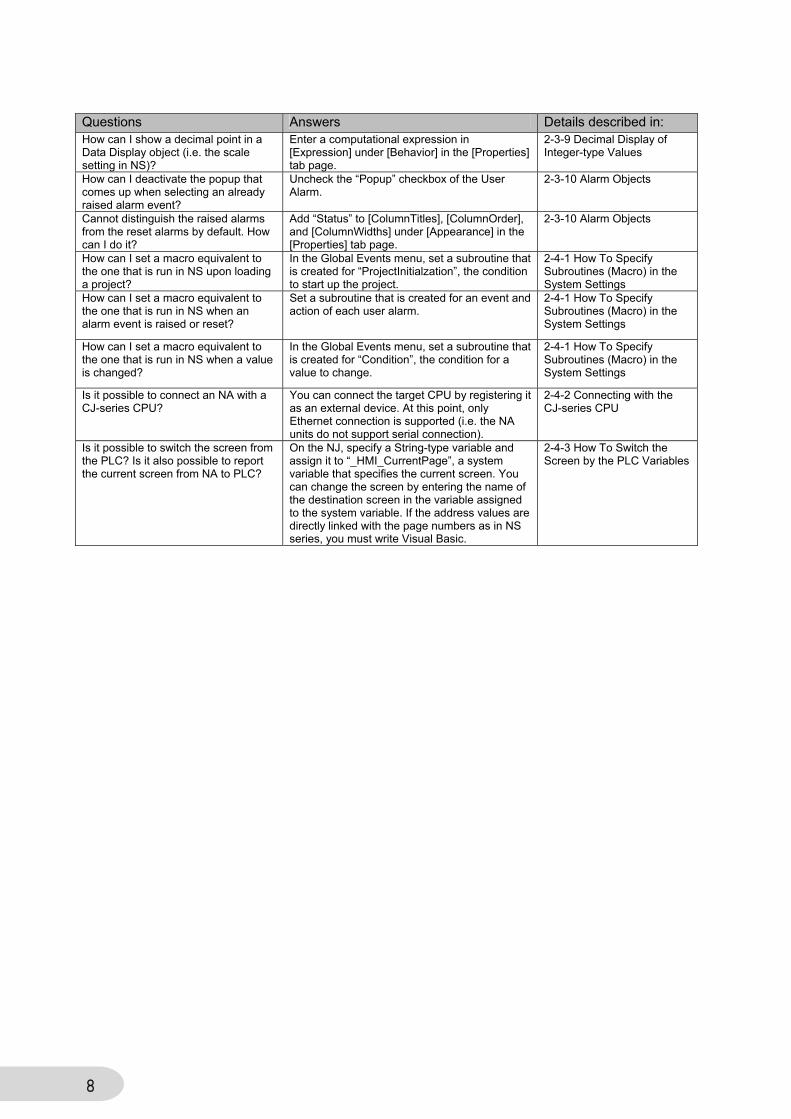
Questions Answers Details described in: How can I show a decimal point in a Data Display object (i.e. the scale setting in NS)?
Enter a computational expression in [Expression] under [Behavior] in the [Properties] tab page.
2-3-9 Decimal Display of Integer-type Values
How can I deactivate the popup that comes up when selecting an already raised alarm event?
Uncheck the “Popup” checkbox of the User Alarm.
2-3-10 Alarm Objects
Cannot distinguish the raised alarms from the reset alarms by default. How can I do it?
Add “Status” to [ColumnTitles], [ColumnOrder], and [ColumnWidths] under [Appearance] in the [Properties] tab page.
2-3-10 Alarm Objects
How can I set a macro equivalent to the one that is run in NS upon loading a project?
In the Global Events menu, set a subroutine that is created for “ProjectInitialzation”, the condition to start up the project.
2-4-1 How To Specify Subroutines (Macro) in the System Settings
How can I set a macro equivalent to the one that is run in NS when an alarm event is raised or reset?
Set a subroutine that is created for an event and action of each user alarm.
2-4-1 How To Specify Subroutines (Macro) in the System Settings
How can I set a macro equivalent to the one that is run in NS when a value is changed?
In the Global Events menu, set a subroutine that is created for “Condition”, the condition for a value to change.
2-4-1 How To Specify Subroutines (Macro) in the System Settings
Is it possible to connect an NA with a CJ-series CPU?
You can connect the target CPU by registering it as an external device. At this point, only Ethernet connection is supported (i.e. the NA units do not support serial connection).
2-4-2 Connecting with the CJ-series CPU
Is it possible to switch the screen from the PLC? Is it also possible to report the current screen from NA to PLC?
On the NJ, specify a String-type variable and assign it to “_HMI_CurrentPage”, a system variable that specifies the current screen. You can change the screen by entering the name of the destination screen in the variable assigned to the system variable. If the address values are directly linked with the page numbers as in NS series, you must write Visual Basic.
2-4-3 How To Switch the Screen by the PLC Variables
9
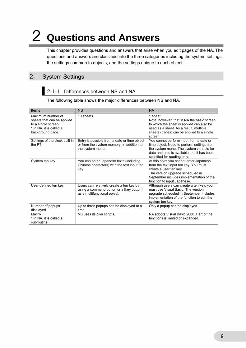
2 Questions and Answers This chapter provides questions and answers that arise when you edit pages of the NA. The
questions and answers are classified into the three categories including the system settings,
the settings common to objects, and the settings unique to each object.
2-1 System Settings
2-1-1 Differences between NS and NA
The following table shows the major differences between NS and NA.
Items NS NA
Maximum number of sheets that can be applied to a single screen * In NA, it is called a background page.
10 sheets 1 sheet Note, however, that in NA the basic screen to which the sheet is applied can also be used as a sheet. As a result, multiple sheets (pages) can be applied to a single screen.
Settings of the clock built in the PT
Entry is possible from a date or time object or from the system memory, in addition to the system menu.
You cannot perform input from a date or time object. Need to perform settings from the system menu. The system variable for date and time is available, but it has been specified for reading only.
System ten key You can enter Japanese texts (including Chinese characters) with the text input ten key.
At this point you cannot enter Japanese from the text input ten key. You must create a user ten key. The version upgrade scheduled in September includes implementation of the function to input Japanese.
User-defined ten key Users can relatively create a ten key by using a command button or a [key button] as a multifunctional object.
Although users can create a ten key, you must use Visual Basic. The version upgrade scheduled in September includes implementation of the function to edit the system ten key.
Number of popups displayed
Up to three popups can be displayed at a time.
Only a popup can be displayed.
Macro * In NA, it is called a subroutine.
NS uses its own scripts. NA adopts Visual Basic 2008. Part of the functions is limited or expanded.
10
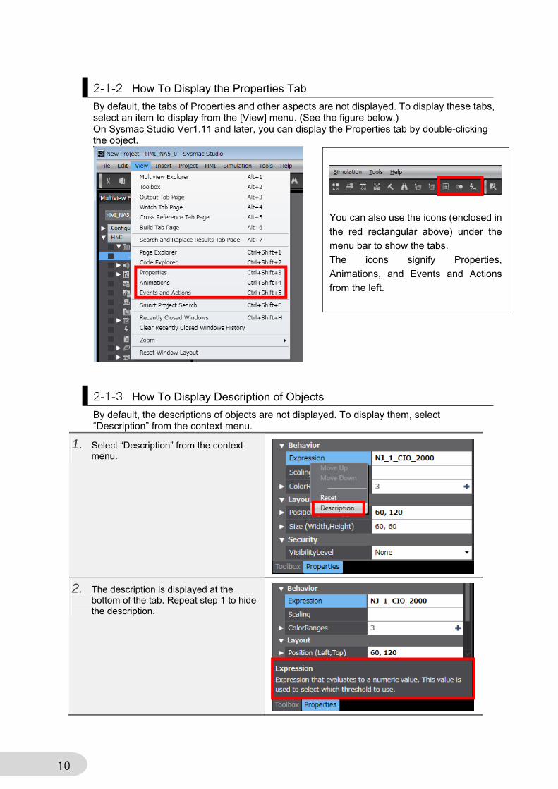
2-1-2 How To Display the Properties Tab
By default, the tabs of Properties and other aspects are not displayed. To display these tabs, select an item to display from the [View] menu. (See the figure below.) On Sysmac Studio Ver1.11 and later, you can display the Properties tab by double-clicking the object.
2-1-3 How To Display Description of Objects
By default, the descriptions of objects are not displayed. To display them, select “Description” from the context menu.
1. Select “Description” from the context menu.
2. The description is displayed at the bottom of the tab. Repeat step 1 to hide the description.
You can also use the icons (enclosed in
the red rectangular above) under the
menu bar to show the tabs.
The icons signify Properties,
Animations, and Events and Actions
from the left.
11
2-2 Functions Common to Objects This section describes the functions that are common to several objects.
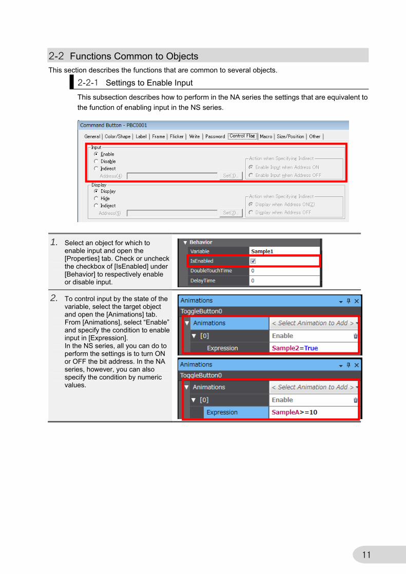
2-2-1 Settings to Enable Input
This subsection describes how to perform in the NA series the settings that are equivalent to
the function of enabling input in the NS series.
1. Select an object for which to enable input and open the [Properties] tab. Check or uncheck the checkbox of [IsEnabled] under [Behavior] to respectively enable or disable input.
2. To control input by the state of the variable, select the target object and open the [Animations] tab. From [Animations], select “Enable” and specify the condition to enable input in [Expression]. In the NS series, all you can do to perform the settings is to turn ON or OFF the bit address. In the NA series, however, you can also specify the condition by numeric values.
12
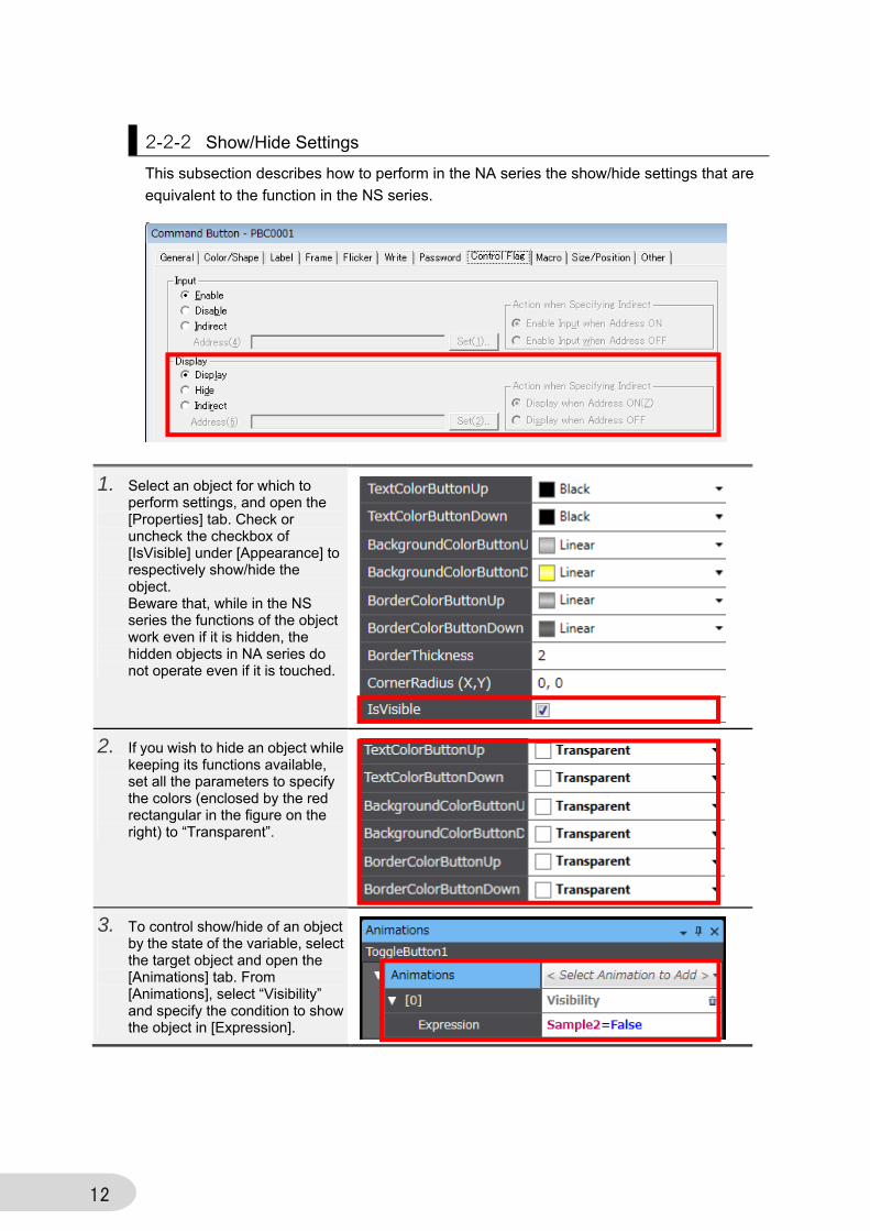
2-2-2 Show/Hide Settings
This subsection describes how to perform in the NA series the show/hide settings that are
equivalent to the function in the NS series.
1. Select an object for which to perform settings, and open the [Properties] tab. Check or uncheck the checkbox of [IsVisible] under [Appearance] to respectively show/hide the object. Beware that, while in the NS series the functions of the object work even if it is hidden, the hidden objects in NA series do not operate even if it is touched.
2. If you wish to hide an object while keeping its functions available, set all the parameters to specify the colors (enclosed by the red rectangular in the figure on the right) to “Transparent”.
3. To control show/hide of an object by the state of the variable, select the target object and open the [Animations] tab. From [Animations], select “Visibility” and specify the condition to show the object in [Expression].
13
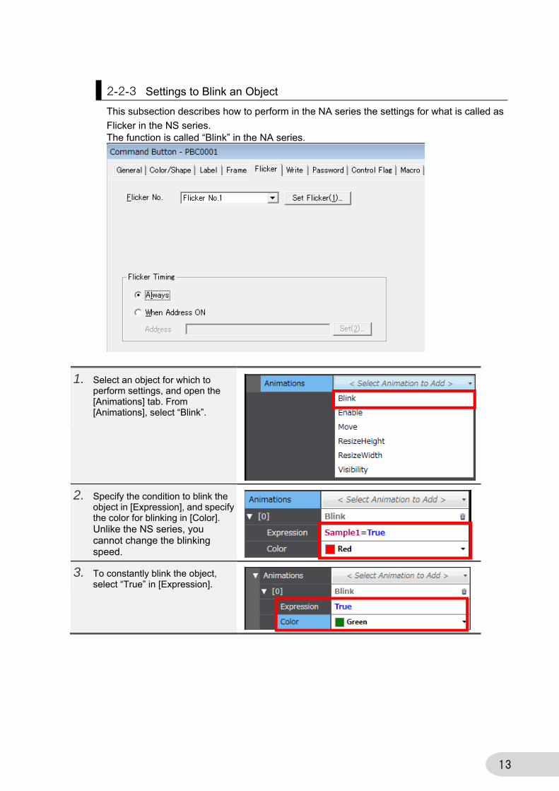
2-2-3 Settings to Blink an Object
This subsection describes how to perform in the NA series the settings for what is called as
Flicker in the NS series. The function is called “Blink” in the NA series.
1. Select an object for which to perform settings, and open the [Animations] tab. From [Animations], select “Blink”.
2. Specify the condition to blink the object in [Expression], and specify the color for blinking in [Color]. Unlike the NS series, you cannot change the blinking speed.
3. To constantly blink the object, select “True” in [Expression].
14
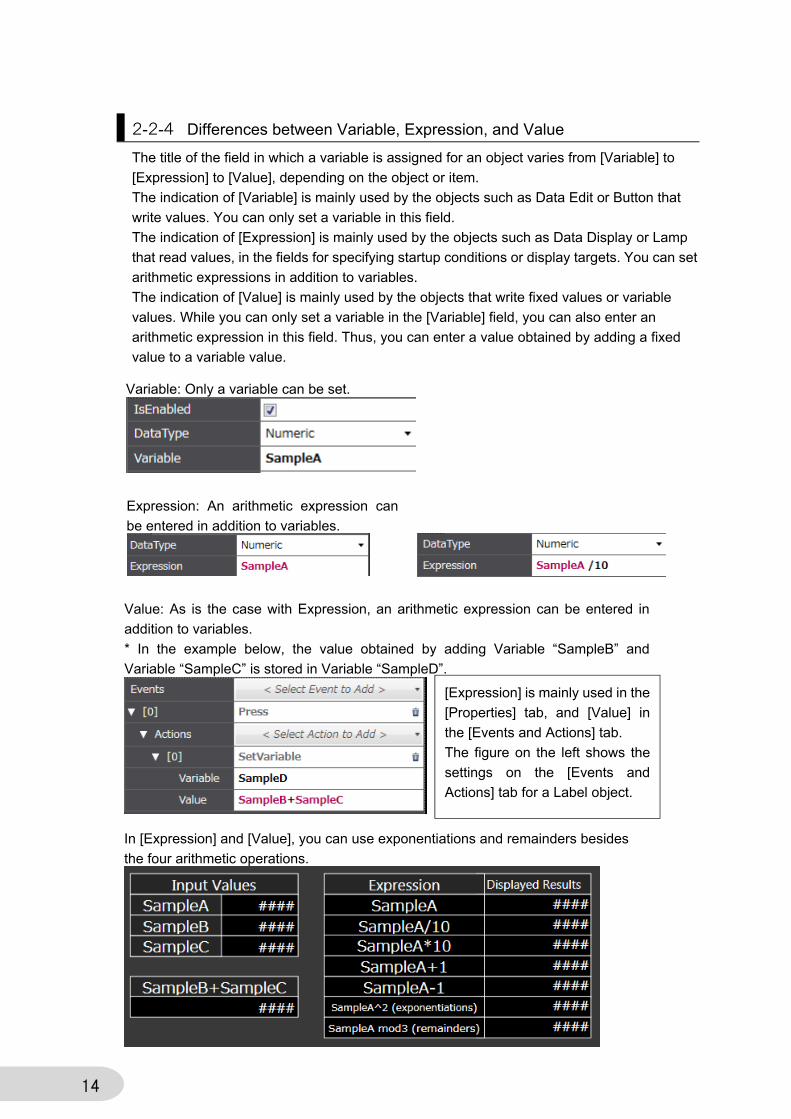
2-2-4 Differences between Variable, Expression, and Value
The title of the field in which a variable is assigned for an object varies from [Variable] to
[Expression] to [Value], depending on the object or item.
The indication of [Variable] is mainly used by the objects such as Data Edit or Button that
write values. You can only set a variable in this field.
The indication of [Expression] is mainly used by the objects such as Data Display or Lamp
that read values, in the fields for specifying startup conditions or display targets. You can set
arithmetic expressions in addition to variables.
The indication of [Value] is mainly used by the objects that write fixed values or variable
values. While you can only set a variable in the [Variable] field, you can also enter an
arithmetic expression in this field. Thus, you can enter a value obtained by adding a fixed
value to a variable value.
Variable: Only a variable can be set.
Expression: An arithmetic expression can
be entered in addition to variables.
Value: As is the case with Expression, an arithmetic expression can be entered in
addition to variables.
* In the example below, the value obtained by adding Variable “SampleB” and
Variable “SampleC” is stored in Variable “SampleD”.
In [Expression] and [Value], you can use exponentiations and remainders besides
the four arithmetic operations.
[Expression] is mainly used in the
[Properties] tab, and [Value] in
the [Events and Actions] tab.
The figure on the left shows the
settings on the [Events and
Actions] tab for a Label object.
15
2-3 Functions Unique to Each Object This section describes the functions of the individual object.
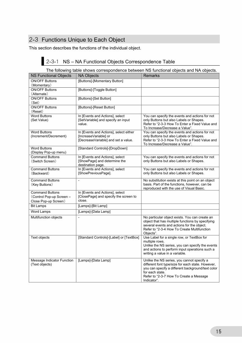
2-3-1 NS – NA Functional Objects Correspondence Table
The following table shows correspondence between NS functional objects and NA objects. NS Functional Objects NA Objects Remarks ON/OFF Buttons (Momentary)
[Buttons]-[Momentary Button]
ON/OFF Buttons (Alternate)
[Buttons]-[Toggle Button]
ON/OFF Buttons (Set)
[Buttons]-[Set Button]
ON/OFF Buttons (Reset)
[Buttons]-[Reset Button]
Word Buttons (Set Value)
In [Events and Actions], select [SetVariable] and specify an input value.
You can specify the events and actions for not only Buttons but also Labels or Shapes. Refer to “2-3-3 How To Enter a Fixed Value and To Increase/Decrease a Value”.
Word Buttons (Increment/Decrement)
In [Events and Actions], select either [IncreaseVariable] or [DecreaseVariable] and set a value.
You can specify the events and actions for not only Buttons but also Labels or Shapes. Refer to “2-3-3 How To Enter a Fixed Value and To Increase/Decrease a Value”.
Word Buttons (Display Pop-up menu)
[Standard Controls]-[DropDown]
Command Buttons (Switch Screen)
In [Events and Actions], select [ShowPage] and determine the destination page.
You can specify the events and actions for not only Buttons but also Labels or Shapes.
Command Buttons (Backward)
In [Events and Actions], select [ShowPreviousPage].
You can specify the events and actions for not only Buttons but also Labels or Shapes.
Command Buttons (Key Buttons)
- No substitution exists at this point on an object basis. Part of the functions, however, can be reproduced with the use of Visual Basic.
Command Buttons (Control Pop-up Screen – Close Pop-up Screen)
In [Events and Actions], select [ClosePage] and specify the screen to close.
Bit Lamps [Lamps]-[Bit Lamp]
Word Lamps [Lamps]-[Data Lamp]
Multifunction objects - No particular object exists. You can create an object that has multiple functions by specifying several events and actions for the object. Refer to “2-3-4 How To Create Multifunction Objects”.
Text objects [Standard Controls]-[Label] or [TextBox] Use Label for a single row, or TextBox for multiple rows. Unlike the NS series, you can specify the events and actions to perform input operations such a writing a value in a variable.
Message Indicator Function (Text objects)
[Lamps]-[Data Lamp] Unlike the NS series, you cannot specify a different font type/size for each state. However, you can specify a different background/text color for each state. Refer to “2-3-7 How To Create a Message Indicator”.
16
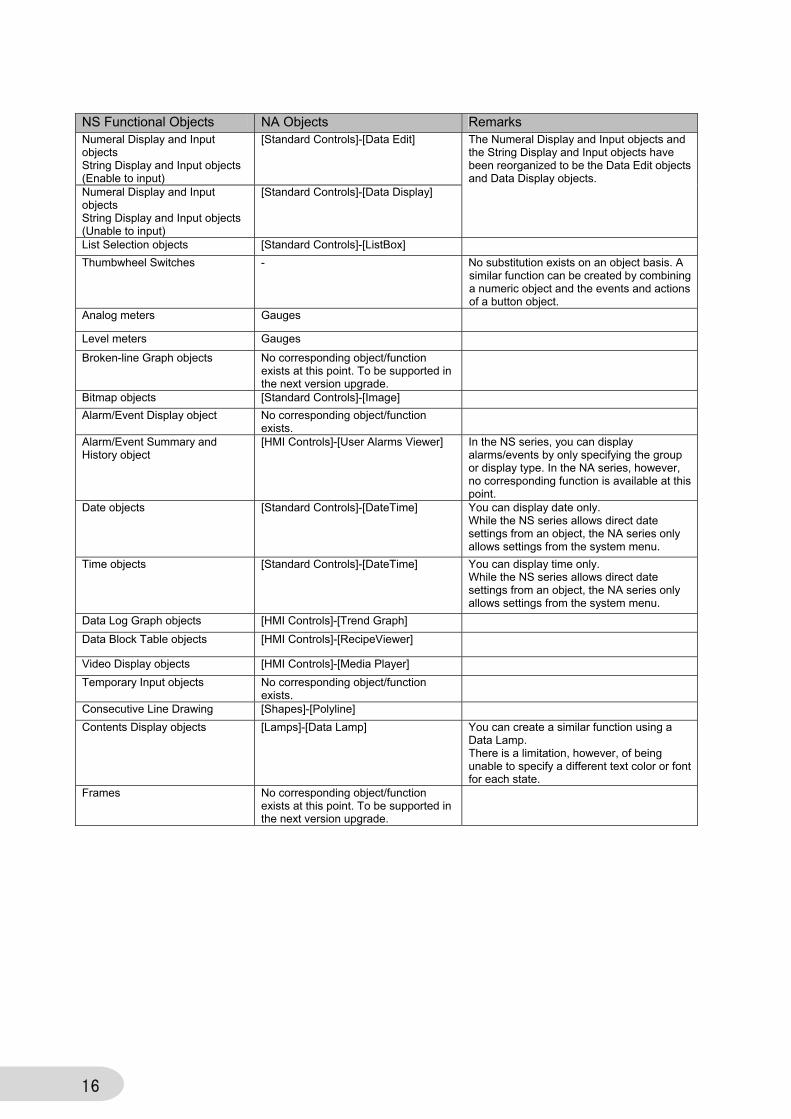
NS Functional Objects NA Objects Remarks Numeral Display and Input objects String Display and Input objects (Enable to input)
[Standard Controls]-[Data Edit] The Numeral Display and Input objects and the String Display and Input objects have been reorganized to be the Data Edit objects and Data Display objects.
Numeral Display and Input objects String Display and Input objects (Unable to input)
[Standard Controls]-[Data Display]
List Selection objects [Standard Controls]-[ListBox]
Thumbwheel Switches - No substitution exists on an object basis. A similar function can be created by combining a numeric object and the events and actions of a button object.
Analog meters Gauges
Level meters Gauges
Broken-line Graph objects No corresponding object/function exists at this point. To be supported in the next version upgrade.
Bitmap objects [Standard Controls]-[Image]
Alarm/Event Display object No corresponding object/function exists.
Alarm/Event Summary and History object
[HMI Controls]-[User Alarms Viewer] In the NS series, you can display alarms/events by only specifying the group or display type. In the NA series, however, no corresponding function is available at this point.
Date objects [Standard Controls]-[DateTime] You can display date only. While the NS series allows direct date settings from an object, the NA series only allows settings from the system menu.
Time objects [Standard Controls]-[DateTime] You can display time only. While the NS series allows direct date settings from an object, the NA series only allows settings from the system menu.
Data Log Graph objects [HMI Controls]-[Trend Graph]
Data Block Table objects [HMI Controls]-[RecipeViewer]
Video Display objects [HMI Controls]-[Media Player]
Temporary Input objects No corresponding object/function exists.
Consecutive Line Drawing [Shapes]-[Polyline]
Contents Display objects [Lamps]-[Data Lamp] You can create a similar function using a Data Lamp. There is a limitation, however, of being unable to specify a different text color or font for each state.
Frames No corresponding object/function exists at this point. To be supported in the next version upgrade.
17
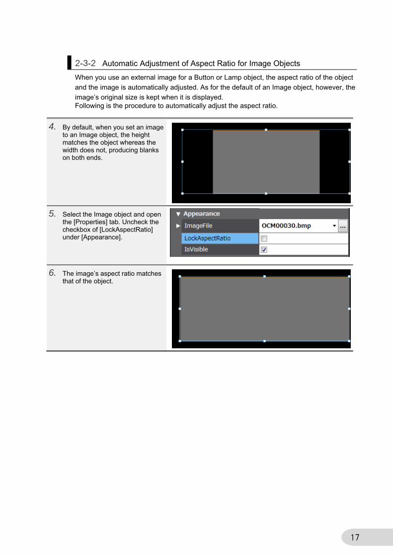
2-3-2 Automatic Adjustment of Aspect Ratio for Image Objects
When you use an external image for a Button or Lamp object, the aspect ratio of the object
and the image is automatically adjusted. As for the default of an Image object, however, the
image’s original size is kept when it is displayed. Following is the procedure to automatically adjust the aspect ratio.
4. By default, when you set an image to an Image object, the height matches the object whereas the width does not, producing blanks on both ends.
5. Select the Image object and open the [Properties] tab. Uncheck the checkbox of [LockAspectRatio] under [Appearance].
6. The image’s aspect ratio matches that of the object.

18
2-3-3 How To Enter a Fixed Value and To Increase/Decrease a Value
To enter a fixed value or to increase or decrease a value in a variable or address in the NS
series, you use a Word Button. In the NA series, you use Events and Actions.
Entering a Fixed Value
1. Select [Buttons] – [Button] in the Toolbox. Drag and drop it to the page.
2. In the [Events and Actions] tab page, select “click” as [Events] and “SetVariable” as [Actions]. Then, set a target variable in [Variable] and an input value in [Value].
3. You can indirectly specify the input value by setting a variable instead of a fixed value in [Value]. The example on the right shows the value of Variable SampleC is entered in SampleB.
19
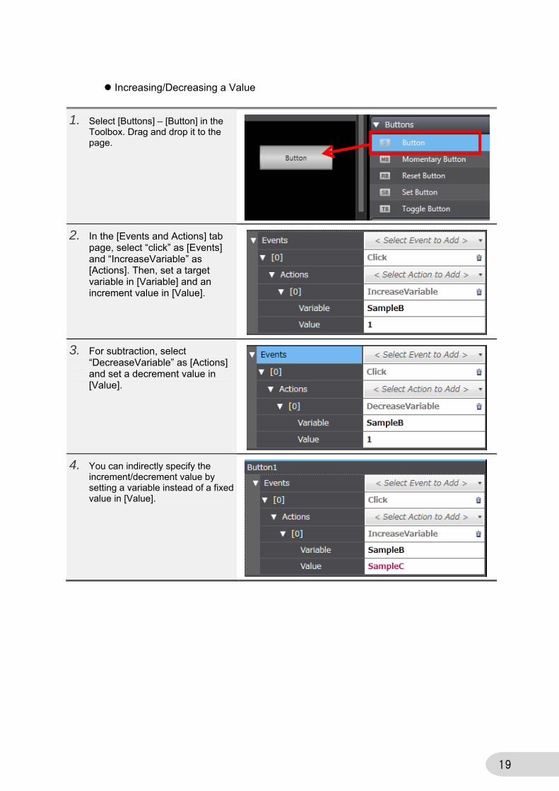
Increasing/Decreasing a Value
1. Select [Buttons] – [Button] in the Toolbox. Drag and drop it to the page.
2. In the [Events and Actions] tab page, select “click” as [Events] and “IncreaseVariable” as [Actions]. Then, set a target variable in [Variable] and an increment value in [Value].
3. For subtraction, select “DecreaseVariable” as [Actions] and set a decrement value in [Value].
4. You can indirectly specify the increment/decrement value by setting a variable instead of a fixed value in [Value].

20
2-3-4 How To Create Multifunction Objects
In the NS series, there exist the Multifunction objects that have multiple functions within the
single object. In the NA series, by contrast, such objects that are dedicated for multifunction
do not exist. You can realize multifunction, however, by assigning multiple events and
actions to a single object.
1. Select [Buttons] – [Button] in the Toolbox. Drag and drop it to the page.
2. In the [Events and Actions] tab page, select “click” as [Events] and “SetVariable” as [Actions]. Then, set the target variable in [Variable] and an input value in [Value].
3. Subsequently select “SetVariable” as [Actions] and set a target variable in [Variable] and an input value in [Value], both of which are different from those set in Step 2 above.
21
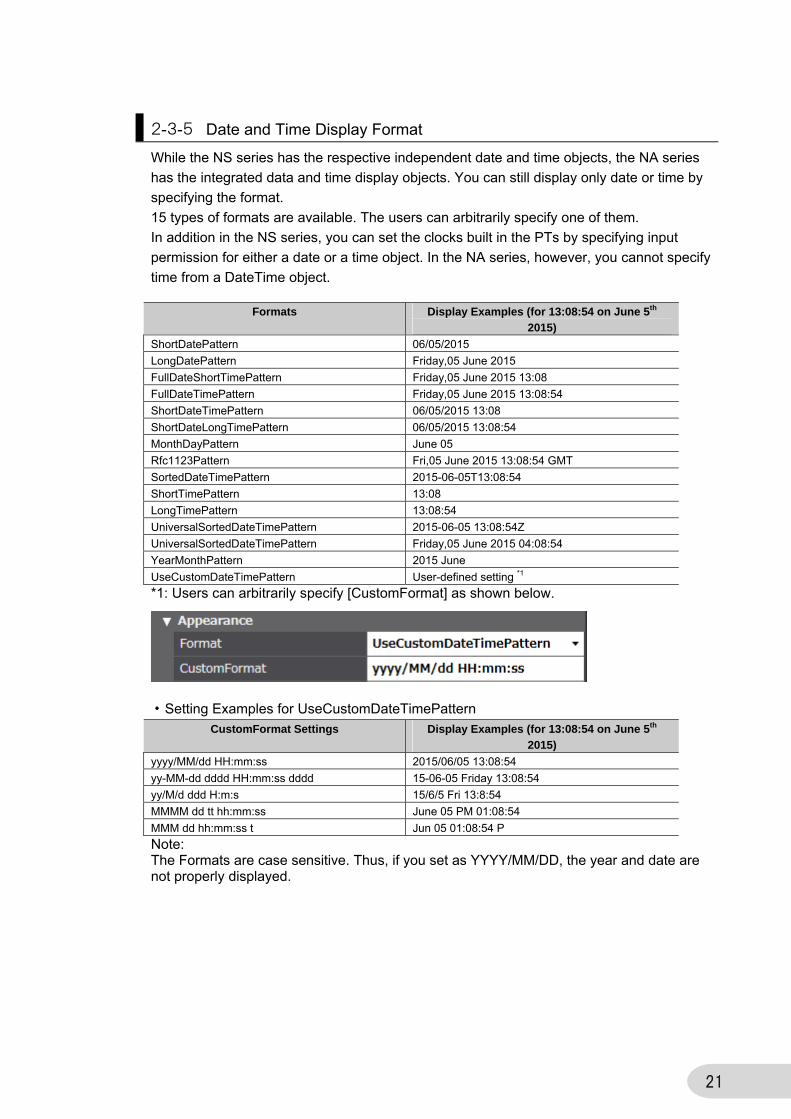
2-3-5 Date and Time Display Format
While the NS series has the respective independent date and time objects, the NA series
has the integrated data and time display objects. You can still display only date or time by
specifying the format.
15 types of formats are available. The users can arbitrarily specify one of them.
In addition in the NS series, you can set the clocks built in the PTs by specifying input
permission for either a date or a time object. In the NA series, however, you cannot specify
time from a DateTime object.
Formats Display Examples (for 13:08:54 on June 5th
2015)
ShortDatePattern 06/05/2015
LongDatePattern Friday,05 June 2015
FullDateShortTimePattern Friday,05 June 2015 13:08
FullDateTimePattern Friday,05 June 2015 13:08:54
ShortDateTimePattern 06/05/2015 13:08
ShortDateLongTimePattern 06/05/2015 13:08:54
MonthDayPattern June 05
Rfc1123Pattern Fri,05 June 2015 13:08:54 GMT
SortedDateTimePattern 2015-06-05T13:08:54
ShortTimePattern 13:08
LongTimePattern 13:08:54
UniversalSortedDateTimePattern 2015-06-05 13:08:54Z
UniversalSortedDateTimePattern Friday,05 June 2015 04:08:54
YearMonthPattern 2015 June
UseCustomDateTimePattern User-defined setting *1
*1: Users can arbitrarily specify [CustomFormat] as shown below.
・Setting Examples for UseCustomDateTimePattern
CustomFormat Settings Display Examples (for 13:08:54 on June 5th
2015)
yyyy/MM/dd HH:mm:ss 2015/06/05 13:08:54
yy-MM-dd dddd HH:mm:ss dddd 15-06-05 Friday 13:08:54
yy/M/d ddd H:m:s 15/6/5 Fri 13:8:54
MMMM dd tt hh:mm:ss June 05 PM 01:08:54
MMM dd hh:mm:ss t Jun 05 01:08:54 P
Note: The Formats are case sensitive. Thus, if you set as YYYY/MM/DD, the year and date are not properly displayed.
22
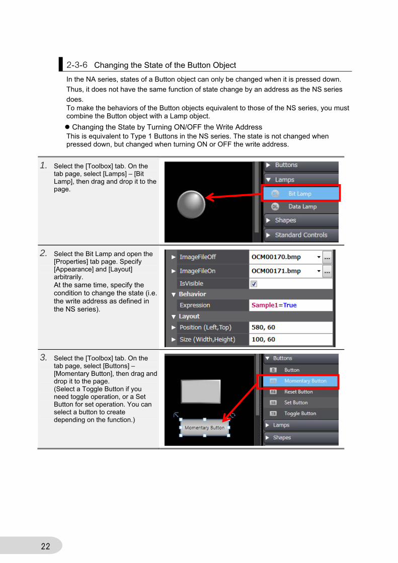
2-3-6 Changing the State of the Button Object
In the NA series, states of a Button object can only be changed when it is pressed down.
Thus, it does not have the same function of state change by an address as the NS series
does. To make the behaviors of the Button objects equivalent to those of the NS series, you must combine the Button object with a Lamp object.
Changing the State by Turning ON/OFF the Write Address This is equivalent to Type 1 Buttons in the NS series. The state is not changed when pressed down, but changed when turning ON or OFF the write address.
1. Select the [Toolbox] tab. On the tab page, select [Lamps] – [Bit Lamp], then drag and drop it to the page.
2. Select the Bit Lamp and open the [Properties] tab page. Specify [Appearance] and [Layout] arbitrarily. At the same time, specify the condition to change the state (i.e. the write address as defined in the NS series).
3. Select the [Toolbox] tab. On the tab page, select [Buttons] – [Momentary Button], then drag and drop it to the page. (Select a Toggle Button if you need toggle operation, or a Set Button for set operation. You can select a button to create depending on the function.)
23
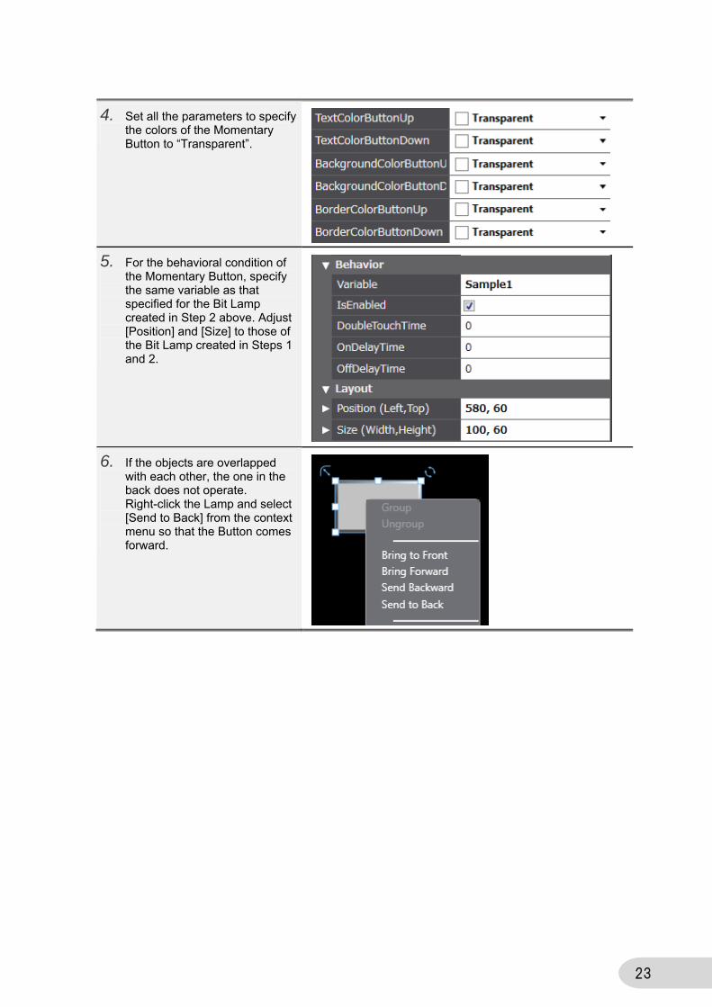
4. Set all the parameters to specify the colors of the Momentary Button to “Transparent”.
5. For the behavioral condition of the Momentary Button, specify the same variable as that specified for the Bit Lamp created in Step 2 above. Adjust [Position] and [Size] to those of the Bit Lamp created in Steps 1 and 2.
6. If the objects are overlapped with each other, the one in the back does not operate. Right-click the Lamp and select [Send to Back] from the context menu so that the Button comes forward.
24
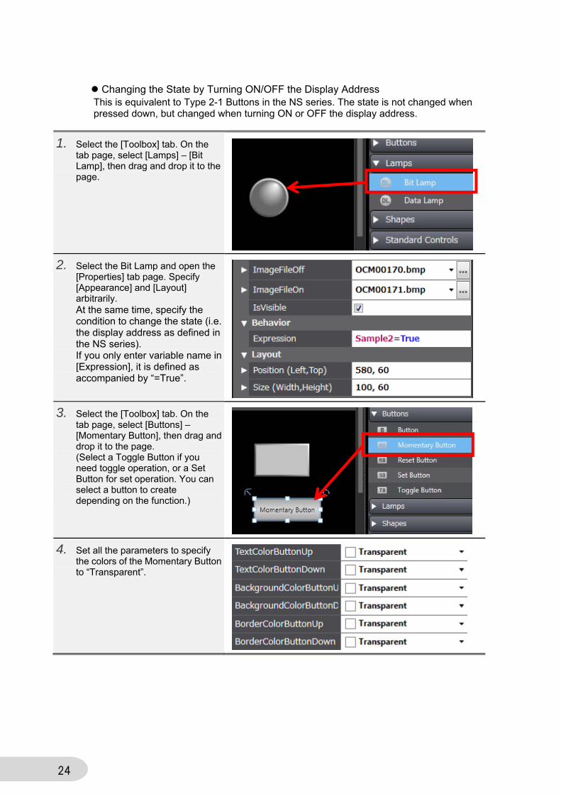
Changing the State by Turning ON/OFF the Display Address This is equivalent to Type 2-1 Buttons in the NS series. The state is not changed when pressed down, but changed when turning ON or OFF the display address.
1. Select the [Toolbox] tab. On the tab page, select [Lamps] – [Bit Lamp], then drag and drop it to the page.
2. Select the Bit Lamp and open the [Properties] tab page. Specify [Appearance] and [Layout] arbitrarily. At the same time, specify the condition to change the state (i.e. the display address as defined in the NS series). If you only enter variable name in [Expression], it is defined as accompanied by “=True”.
3. Select the [Toolbox] tab. On the tab page, select [Buttons] – [Momentary Button], then drag and drop it to the page. (Select a Toggle Button if you need toggle operation, or a Set Button for set operation. You can select a button to create depending on the function.)
4. Set all the parameters to specify the colors of the Momentary Button to “Transparent”.
25
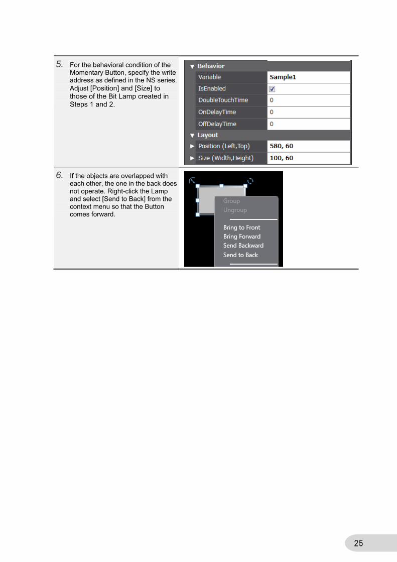
5. For the behavioral condition of the Momentary Button, specify the write address as defined in the NS series. Adjust [Position] and [Size] to those of the Bit Lamp created in Steps 1 and 2.
6. If the objects are overlapped with each other, the one in the back does not operate. Right-click the Lamp and select [Send to Back] from the context menu so that the Button comes forward.

26
2-3-7 How To Create a Message Indicator
In the NS series, there is the Message Indicator that enables its state to be changed by the
value of the variable. In the NA series, you can realize the function by using a Lamp object. Note, however, that in the NS series you can specify the different font type or color for each state whereas in the NA series you cannot change the basic settings. You can still change background or text colors as before.
1. Select [Lamps] – [Data Lamp] in the Toolbox. Drag and drop it to the page.
2. Select the object and open the [Properties] tab page. Specify [Design] under [Appearance] as “Rectangle” to adjust the size arbitrarily.
3. Under [Appearance], specify the text, font type, and other parameters arbitrarily to change them from defaults.
4. Set the variable that controls state change in [Expression] under [Behavior], and click the cross (+) in [ColorRanges].
27
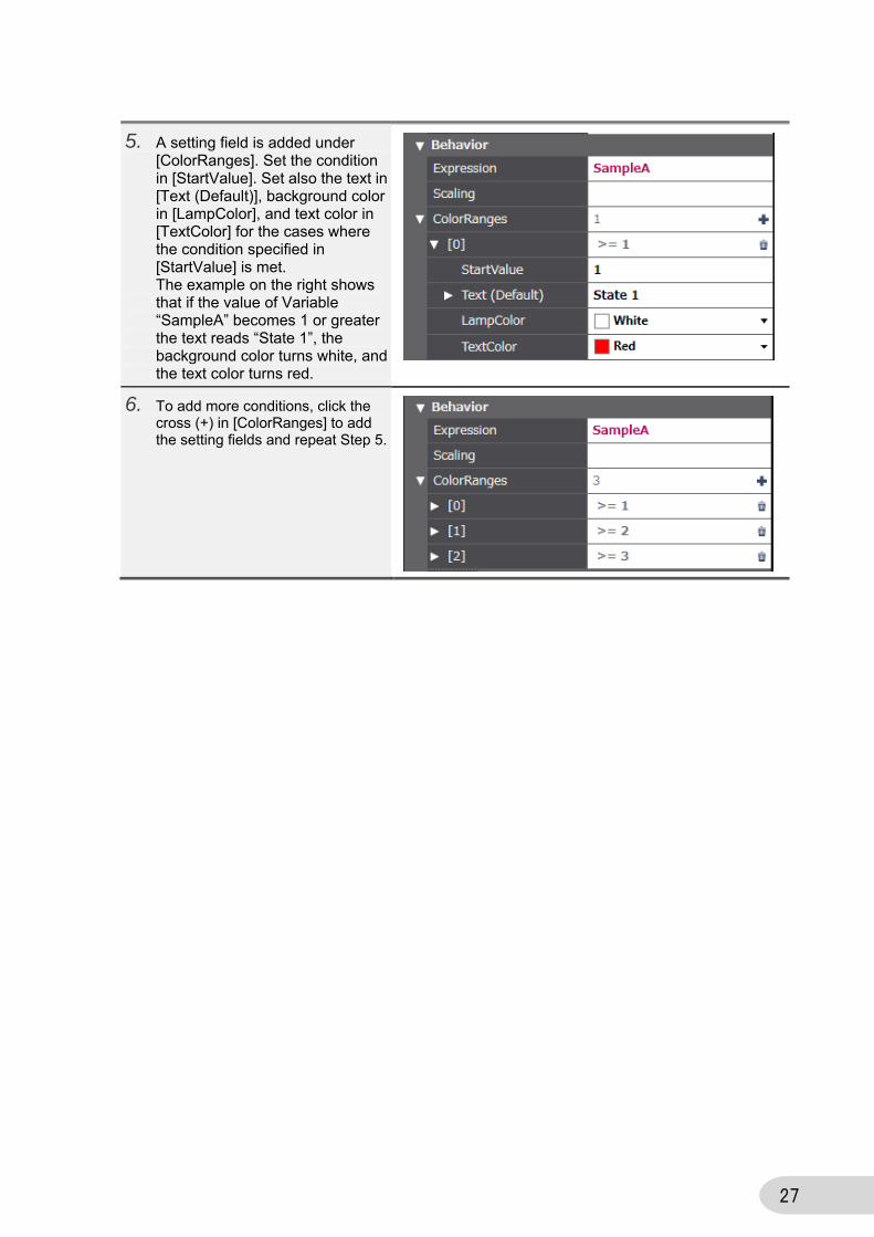
5. A setting field is added under [ColorRanges]. Set the condition in [StartValue]. Set also the text in [Text (Default)], background color in [LampColor], and text color in [TextColor] for the cases where the condition specified in [StartValue] is met. The example on the right shows that if the value of Variable “SampleA” becomes 1 or greater the text reads “State 1”, the background color turns white, and the text color turns red.
6. To add more conditions, click the cross (+) in [ColorRanges] to add the setting fields and repeat Step 5.
28
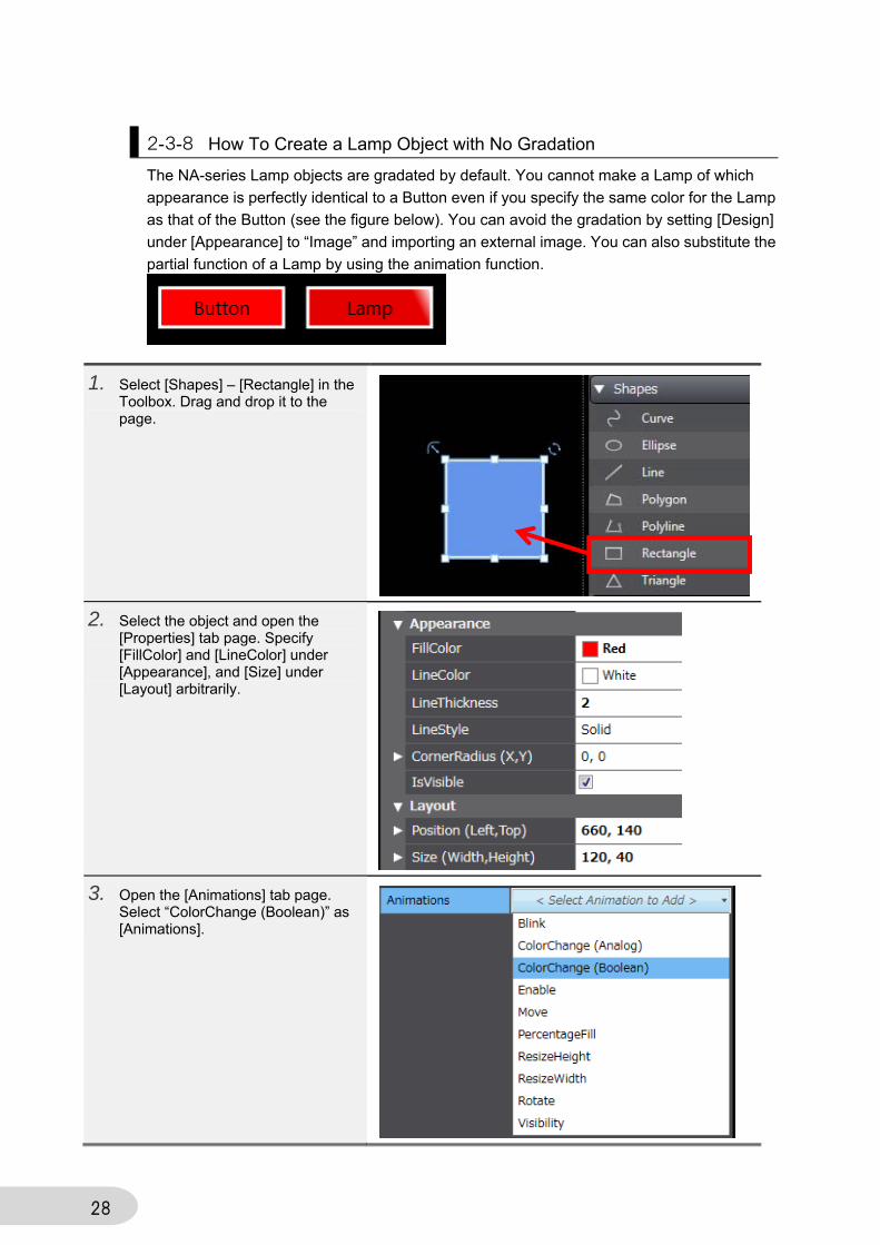
2-3-8 How To Create a Lamp Object with No Gradation
The NA-series Lamp objects are gradated by default. You cannot make a Lamp of which
appearance is perfectly identical to a Button even if you specify the same color for the Lamp
as that of the Button (see the figure below). You can avoid the gradation by setting [Design]
under [Appearance] to “Image” and importing an external image. You can also substitute the
partial function of a Lamp by using the animation function.
1. Select [Shapes] – [Rectangle] in the Toolbox. Drag and drop it to the page.
2. Select the object and open the [Properties] tab page. Specify [FillColor] and [LineColor] under [Appearance], and [Size] under [Layout] arbitrarily.
3. Open the [Animations] tab page. Select “ColorChange (Boolean)” as [Animations].
29
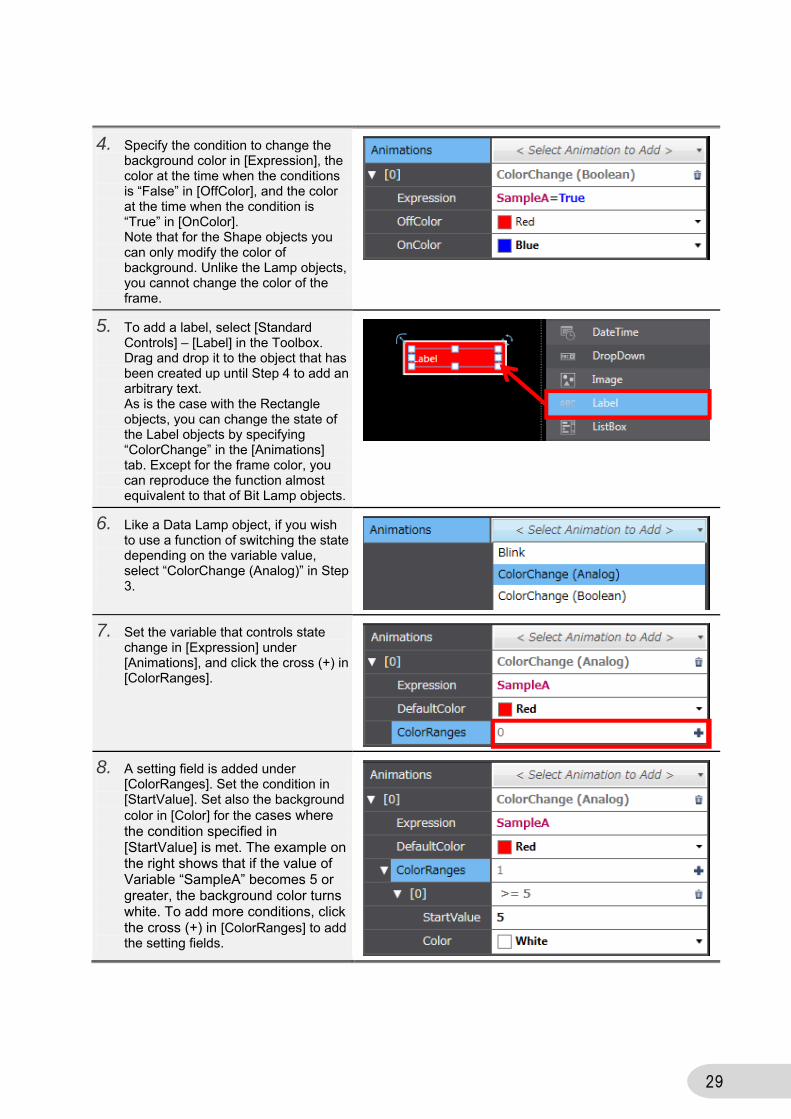
4. Specify the condition to change the background color in [Expression], the color at the time when the conditions is “False” in [OffColor], and the color at the time when the condition is “True” in [OnColor]. Note that for the Shape objects you can only modify the color of background. Unlike the Lamp objects, you cannot change the color of the frame.
5. To add a label, select [Standard Controls] – [Label] in the Toolbox. Drag and drop it to the object that has been created up until Step 4 to add an arbitrary text. As is the case with the Rectangle objects, you can change the state of the Label objects by specifying “ColorChange” in the [Animations] tab. Except for the frame color, you can reproduce the function almost equivalent to that of Bit Lamp objects.
6. Like a Data Lamp object, if you wish to use a function of switching the state depending on the variable value, select “ColorChange (Analog)” in Step 3.
7. Set the variable that controls state change in [Expression] under [Animations], and click the cross (+) in [ColorRanges].
8. A setting field is added under [ColorRanges]. Set the condition in [StartValue]. Set also the background color in [Color] for the cases where the condition specified in [StartValue] is met. The example on the right shows that if the value of Variable “SampleA” becomes 5 or greater, the background color turns white. To add more conditions, click the cross (+) in [ColorRanges] to add the setting fields.
30
2-3-9 Decimal Display of Integer-type Values
This is equivalent to the function specified by “Unit & Scale” in the NS series.
At this point, the Data Display objects are the only objects that can display values with a
decimal point for the integer-type variables, with the use of this function. Because the Data
Edit objects cannot be specified by arithmetic operations, if you wish to deal with decimals,
you must specify the data type of the variable as the floating point type.
The following example explains how to set a scale of “0.1” to Variable “SampleA”.
The scale function is to be implemented for the Data Edit and Data Display objects in the
version upgrade scheduled in September.
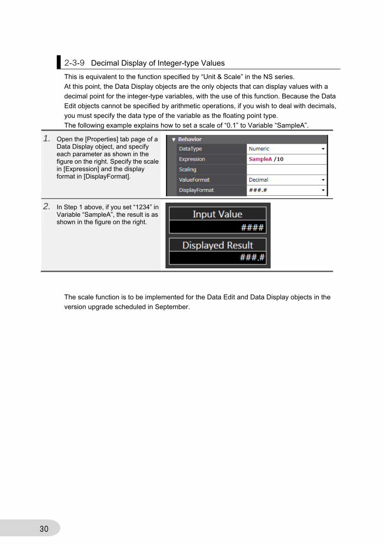
1. Open the [Properties] tab page of a Data Display object, and specify each parameter as shown in the figure on the right. Specify the scale in [Expression] and the display format in [DisplayFormat].
2. In Step 1 above, if you set “1234” in Variable “SampleA”, the result is as shown in the figure on the right.
31
2-3-10 Alarm Objects
The Alarm Objects in the NA series are significantly different from those of the NS series in
terms of the behaviors by the default settings. This subsection describes the alarm settings
more similar to those of the NS series.
How To Disable the Popup Screen Upon Confirming Alarms By default of the NA-series alarm objects, a popup page that includes the alarm’s detailed information comes up when you touch the raised alarm. Following is the procedure to disable the popup page.
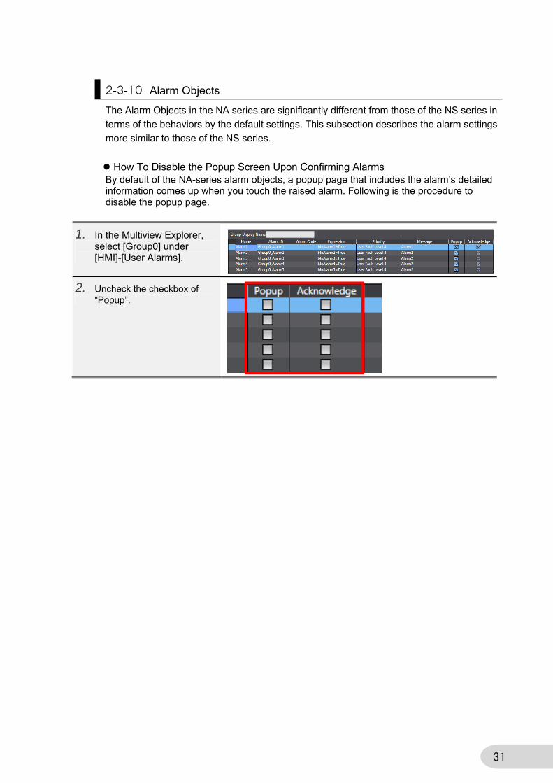
1. In the Multiview Explorer, select [Group0] under [HMI]-[User Alarms].
2. Uncheck the checkbox of “Popup”.
32
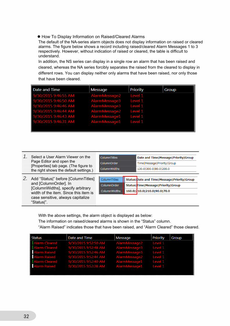
How To Display Information on Raised/Cleared Alarms The default of the NA-series alarm objects does not display information on raised or cleared alarms. The figure below shows a record including raised/cleared Alarm Messages 1 to 3 respectively. However, without indication of raised or cleared, the table is difficult to understand. In addition, the NS series can display in a single row an alarm that has been raised and
cleared, whereas the NA series forcibly separates the raised from the cleared to display in
different rows. You can display neither only alarms that have been raised, nor only those
that have been cleared.
With the above settings, the alarm object is displayed as below:
The information on raised/cleared alarms is shown in the “Status” column.
“Alarm Raised” indicates those that have been raised, and “Alarm Cleared” those cleared.
1. Select a User Alarm Viewer on the Page Editor and open the [Properties] tab page. (The figure to the right shows the default settings.)
2. Add “Status|” before [ColumnTitles] and [ColumnOrder]. In [ColumnWidths], specify arbitrary width of the item. Since this item is case sensitive, always capitalize “Status|”.
33
2-4 Others
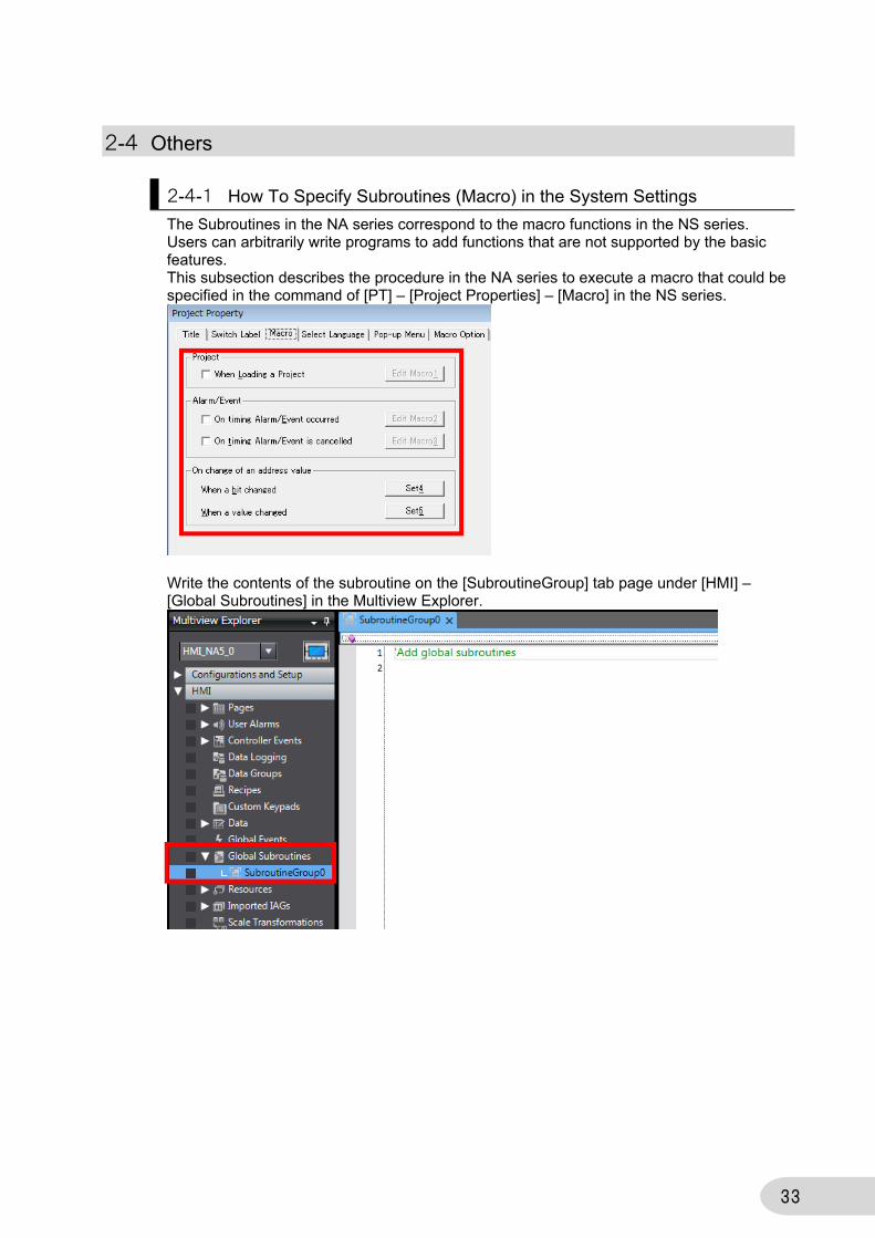
2-4-1 How To Specify Subroutines (Macro) in the System Settings
The Subroutines in the NA series correspond to the macro functions in the NS series. Users can arbitrarily write programs to add functions that are not supported by the basic features. This subsection describes the procedure in the NA series to execute a macro that could be specified in the command of [PT] – [Project Properties] – [Macro] in the NS series.
Write the contents of the subroutine on the [SubroutineGroup] tab page under [HMI] – [Global Subroutines] in the Multiview Explorer.
34
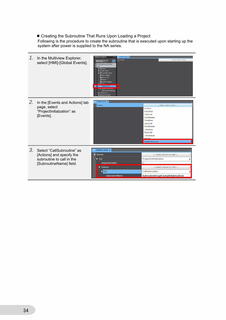
Creating the Subroutine That Runs Upon Loading a Project Following is the procedure to create the subroutine that is executed upon starting up the system after power is supplied to the NA series.
1. In the Multiview Explorer, select [HMI]-[Global Events].
2. In the [Events and Actions] tab page, select “ProjectInitialzation” as [Events].
3. Select “CallSubroutine” as [Actions] and specify the subroutine to call in the [SubroutineName] field.
35
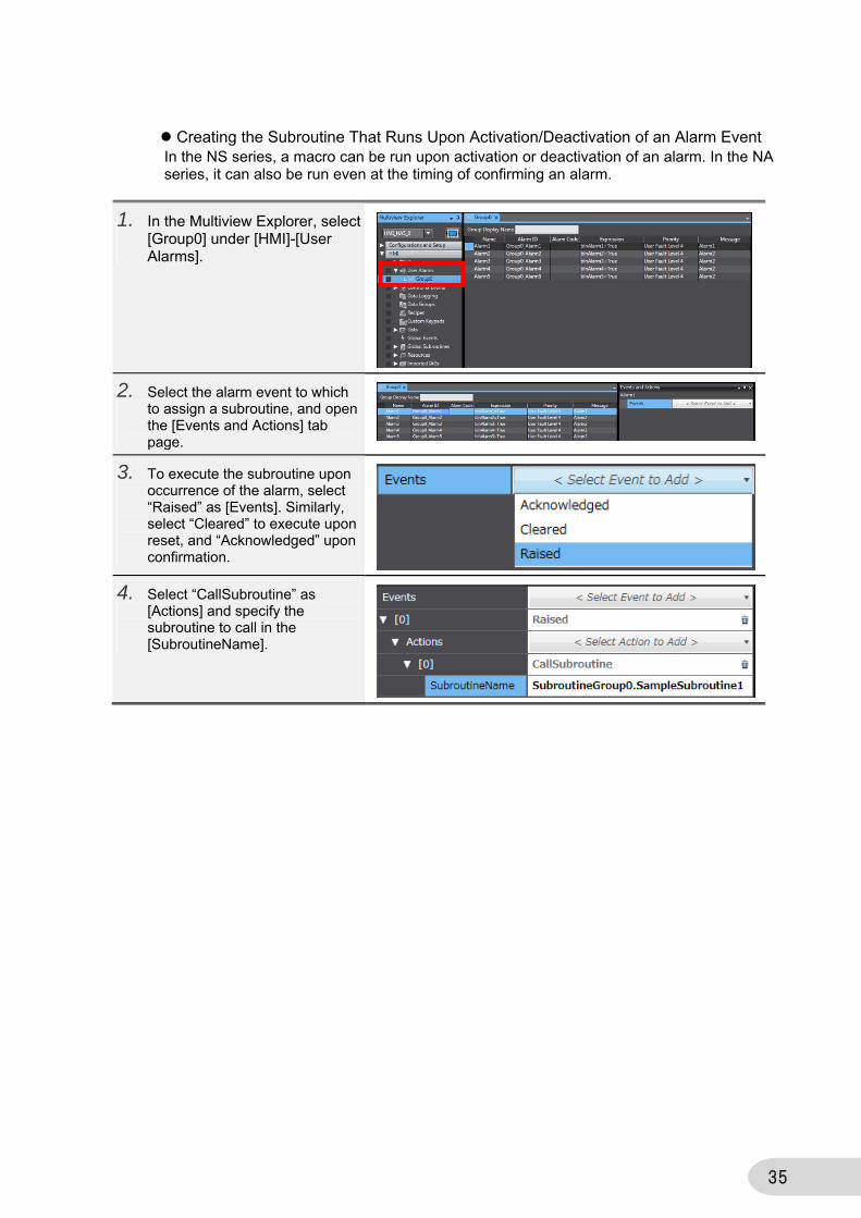
Creating the Subroutine That Runs Upon Activation/Deactivation of an Alarm Event In the NS series, a macro can be run upon activation or deactivation of an alarm. In the NA series, it can also be run even at the timing of confirming an alarm.
1. In the Multiview Explorer, select [Group0] under [HMI]-[User Alarms].
2. Select the alarm event to which to assign a subroutine, and open the [Events and Actions] tab page.
3. To execute the subroutine upon occurrence of the alarm, select “Raised” as [Events]. Similarly, select “Cleared” to execute upon reset, and “Acknowledged” upon confirmation.
4. Select “CallSubroutine” as [Actions] and specify the subroutine to call in the [SubroutineName].

36
Creating the Subroutine That Runs Upon Change of Bit/Value
1. In the Multiview Explorer, select [HMI]-[Global Events].
2. In the [Events and Actions] tab page, select “Condition” as [Events].
3. Specify the condition of subroutine function in the [Expression] field. Then select “CallSubroutine” as [Actions] and specify the subroutine to call in the [SubroutineName] field.

37
2-4-2 Connecting with the CJ-series CPU
The NA series can be connected with the CJ series in addition to the NJ series. To use the variables of the CJ series in NA, you must specify the CJ-series PLC as the connected device, and register the variables of CJ into the NA. Following is the procedure to register the CJ series as the connected device in NA.
There are three ways to register in the NA the variables of the CJ registered as an external device: ・to import the variables directly from the device or to update the variables, ・to directly enter the variables in the variable table, or ・to copy and paste the variables from a file such as Excel. Neither way from among those described above allows import of the CJ’s system variables.
1. In the Multiview Explorer, right-click [Device References] and select [Add] – [External Device].
2. Double-click [ExternalDevice0] that is created under [Device References].
3. In the [ExternalDevice0] tab page, select “CJ” as [Device] in the [Device Configuration] field. Select either “CIP Ethernet” or “FINS Ethernet” as [Communication Driver]. In the [IP Address] field in the [Communications Configuration] field, specify the IP address of the connected PLC.
38
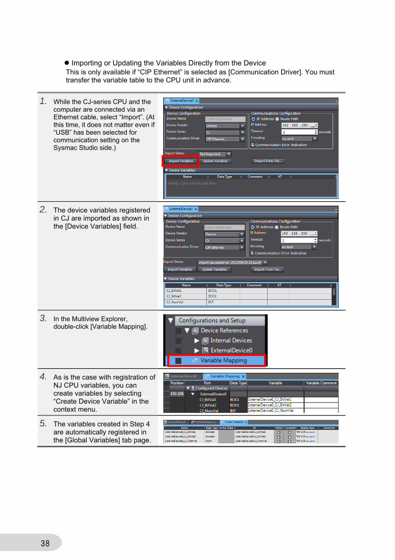
Importing or Updating the Variables Directly from the Device This is only available if “CIP Ethernet” is selected as [Communication Driver]. You must transfer the variable table to the CPU unit in advance.
1. While the CJ-series CPU and the computer are connected via an Ethernet cable, select “Import”. (At this time, it does not matter even if “USB” has been selected for communication setting on the Sysmac Studio side.)
2. The device variables registered in CJ are imported as shown in the [Device Variables] field.
3. In the Multiview Explorer, double-click [Variable Mapping].
4. As is the case with registration of NJ CPU variables, you can create variables by selecting “Create Device Variable” in the context menu.
5. The variables created in Step 4 are automatically registered in the [Global Variables] tab page.
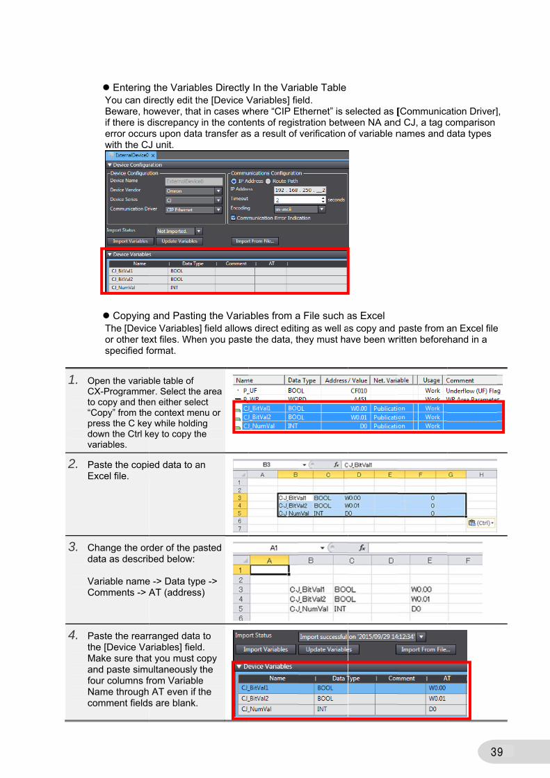
1. OpCXto c“Copredowvar
2. PaExc
3. Chdat VaCo
4. PatheMaandfouNacom
EnteringYou can dBeware, hoif there is derror occuwith the CJ
CopyingThe [Devicor other tespecified fo
pen the variabX-Programmecopy and theopy” from theess the C keywn the Ctrl kriables.
ste the copicel file.
ange the orta as describ
riable nameomments -> A
ste the reare [Device Vaake sure thad paste simuur columns fame through mment fields
g the Variabirectly edit thowever, thatdiscrepancy rs upon dataJ unit.
g and Pastince Variablesxt files. Wheormat.
ble table of er. Select theen either selee context mey while holdin
key to copy th
ed data to a
rder of the pabed below:
e -> Data typAT (address
ranged dataariables] fieldt you must cultaneously rom Variable AT even if ts are blank.
bles Directlyhe [Device Vt in cases win the conte
a transfer as
ng the Varia] field allows
en you paste
e area ect enu or ng he
an
asted
pe -> s)
a to d. copy the e the
y In the VariVariables] fie
where “CIP Eents of regiss a result of
ables from as direct editie the data, t
able Tableeld.
Ethernet” is sstration betwverification
a File such ang as well ahey must ha
selected as [ween NA and
of variable n
as Excel as copy and ave been wr
[Communicad CJ, a tag cnames and d
paste from aritten before
3
ation Driver]comparison data types
an Excel filehand in a
9
],
e
40
2-4-3 How To Switch the Screen by the PLC Variables
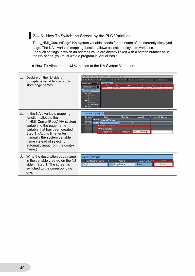
The “_HMI_CurrentPage” NA system variable stands for the name of the currently displayed
page. The NA’s variable mapping function allows allocation of system variables. For such settings in which an address value are directly linked with a screen number as in the NS series, you must write a program in Visual Basic.
How To Allocate the NJ Variables to the NA System Variables
1. Declare on the NJ side a String-type variable in which to store page names.
2. In the NA’s variable mapping function, allocate the “_HMI_CurrentPage” NA system variable to the page name variable that has been created in Step 1. (At this time, enter manually the system variable name instead of selecting automatic input from the context menu.)
3. Write the destination page name in the variable created on the NJ side in Step 1. The screen is switched to the corresponding one.
41
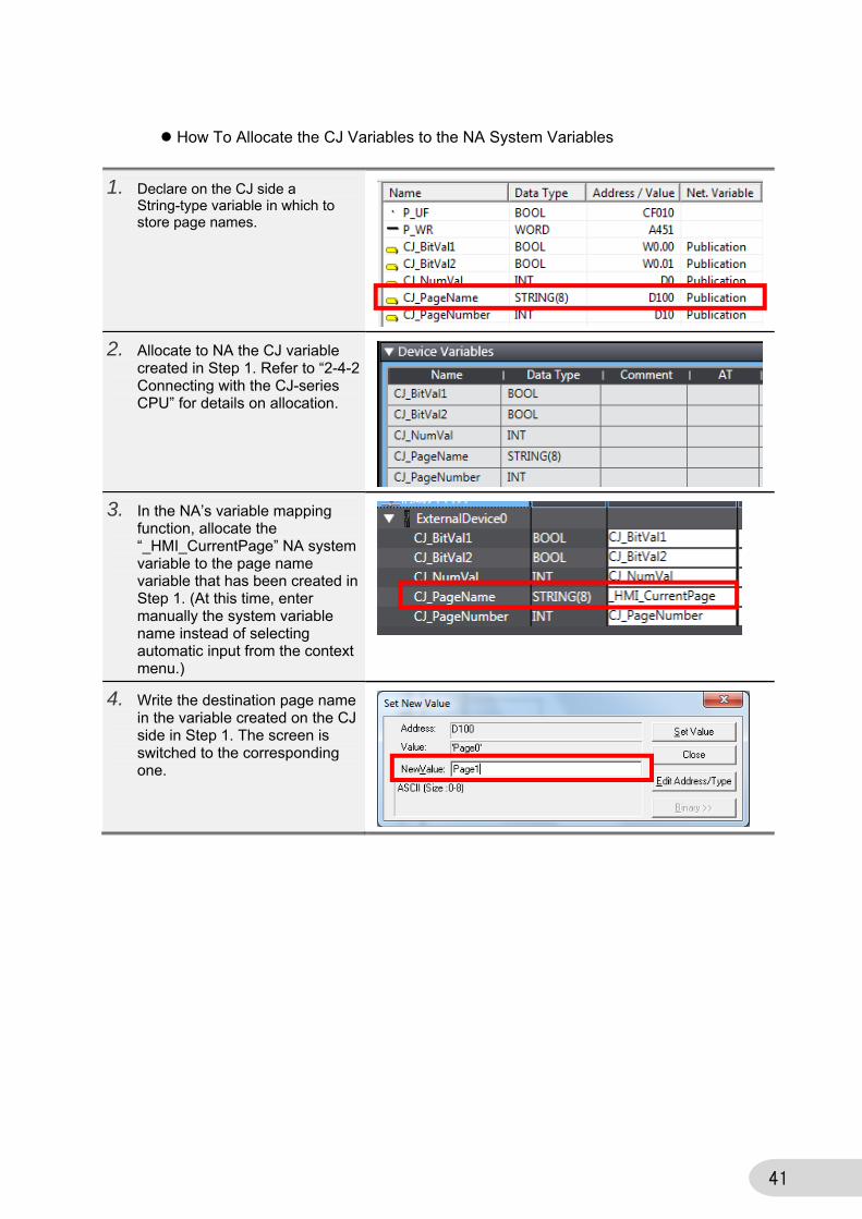
How To Allocate the CJ Variables to the NA System Variables
1. Declare on the CJ side a String-type variable in which to store page names.
2. Allocate to NA the CJ variable created in Step 1. Refer to “2-4-2 Connecting with the CJ-series CPU” for details on allocation.
3. In the NA’s variable mapping function, allocate the “_HMI_CurrentPage” NA system variable to the page name variable that has been created in Step 1. (At this time, enter manually the system variable name instead of selecting automatic input from the context menu.)
4. Write the destination page name in the variable created on the CJ side in Step 1. The screen is switched to the corresponding one.

42
Using Visual Basic (Case Statement) You can use the Case statements of the Visual Basic codes to assign numbers to each screen and to create the behavior to switch to the screen that corresponds with the number.
1. Declare on the NJ side a Numerical-type variable to store page numbers.
2. Allocate on the NA side the variable declared in Step 1. Then declare respectively the String-type variable to store page names and the variable to store page numbers on the NA side. “Page_Name”: Variable to indicate page names “Page_No”: Variable to indicate page numbers on the NA side
3. In the global subroutine, write the code as shown on the right. “PageNameSelect”: switches the NA’s page based on the NJ’s variable value. “PageNumberSelect”: reports to the PLC the number corresponding to the currently displayed page. In either case, to add pages to switch to, increase the conditions of Case.
4. In the [Global Events] tab page, specify the conditions to execute the code created in Step 3 as described below: 1. Indicate the state that the NJ’s page number does not equal to the NA’s page number. 2. Specify the name of the subroutine to execute. 3. Indicate that the action is taken when the page is switched. 4. Specify the name of the subroutine to execute.
5. To switch the page from NJ, modify the “PageNumber” NJ variable. To switch from NA, modify the “_HMI_CurrentPage” NA system variable.
1.
2.
3.
4.
43
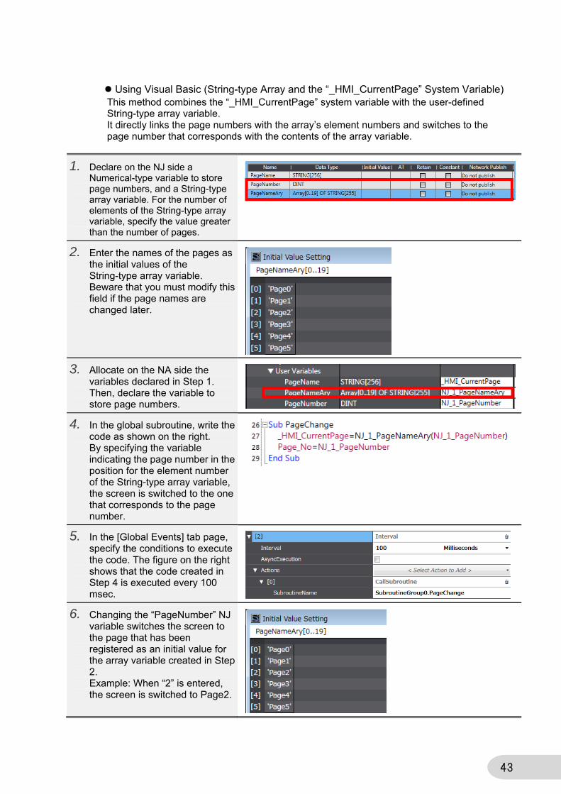
Using Visual Basic (String-type Array and the “_HMI_CurrentPage” System Variable) This method combines the “_HMI_CurrentPage” system variable with the user-defined String-type array variable. It directly links the page numbers with the array’s element numbers and switches to the page number that corresponds with the contents of the array variable.
1. Declare on the NJ side a Numerical-type variable to store page numbers, and a String-type array variable. For the number of elements of the String-type array variable, specify the value greater than the number of pages.
2. Enter the names of the pages as the initial values of the String-type array variable. Beware that you must modify this field if the page names are changed later.
3. Allocate on the NA side the variables declared in Step 1. Then, declare the variable to store page numbers.
4. In the global subroutine, write the code as shown on the right. By specifying the variable indicating the page number in the position for the element number of the String-type array variable, the screen is switched to the one that corresponds to the page number.
5. In the [Global Events] tab page, specify the conditions to execute the code. The figure on the right shows that the code created in Step 4 is executed every 100 msec.
6. Changing the “PageNumber” NJ variable switches the screen to the page that has been registered as an initial value for the array variable created in Step 2. Example: When “2” is entered, the screen is switched to Page2.

44
Using Visual Basic (Switching the Screens by the “Page” Variable) By default, the page name is automatically specified as “Page” followed by the sequential number, such as “Page0”, “Page1”, … You can utilize that to switch screens by fixing the “Page” part while defining the numerical value part as variable, and modifying the variable value. Note, however, that you cannot use this method if the page name has been changed from default.
1. Declare on the NJ side a Numerical-type variable to store page numbers.
2. Declare on the NA side the following variables. NJ_1_PageNumber: links with the page number variables set on the NJ side. Page_No: stores page numbers. Page_Str: set “Page” as the initial value. Used in Visual Basic described below. Page_No_Str: a String-type variable that stores the numerical value part of the Page.
3. In the global subroutine, write the code as shown on the right. By converting the page numbers into text strings and linking them to “Page”, the initial value of “Page_Str”, the text strings such as “Page0” or “Page1” that correspond to the page names are created. The screens can then be switched by assigning the text strings to “_HMI_CurrentPage”, the system variable that indicates page names.
4. In the [Global Events] tab page, specify the conditions to execute the code created in Step 3. The figure on the right shows that the code created in Step 4 is executed every 100 msec.
5. Changing the value of the “PageNumber” NJ variable switches the screen from the PLC.
45
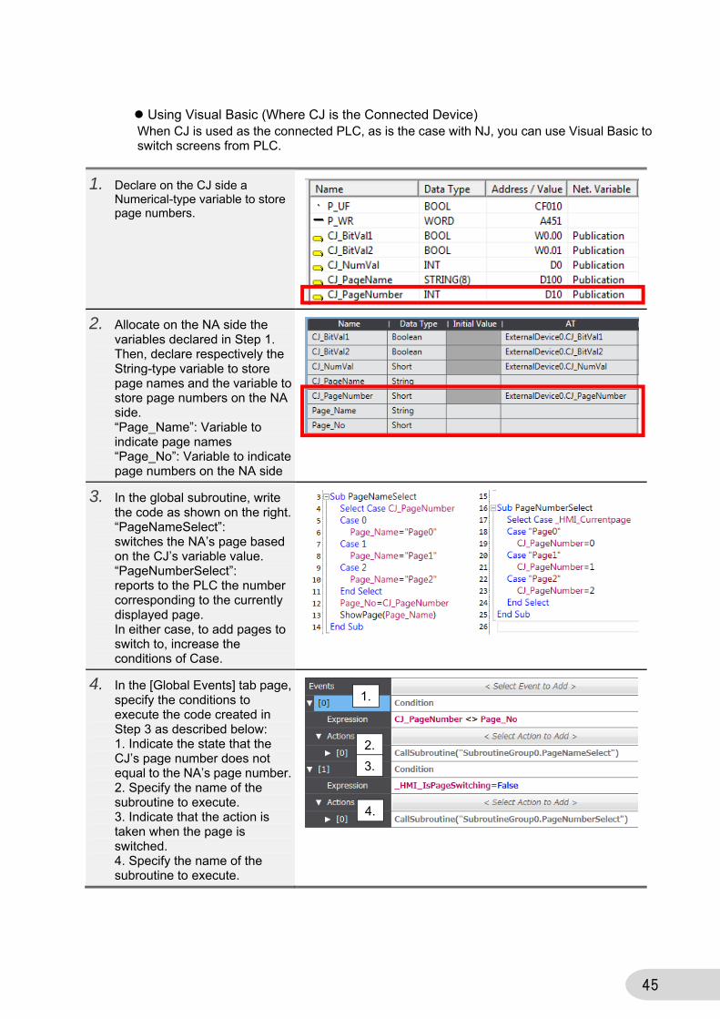
Using Visual Basic (Where CJ is the Connected Device) When CJ is used as the connected PLC, as is the case with NJ, you can use Visual Basic to switch screens from PLC.
1. Declare on the CJ side a Numerical-type variable to store page numbers.
2. Allocate on the NA side the variables declared in Step 1. Then, declare respectively the String-type variable to store page names and the variable to store page numbers on the NA side. “Page_Name”: Variable to indicate page names “Page_No”: Variable to indicate page numbers on the NA side
3. In the global subroutine, write the code as shown on the right. “PageNameSelect”: switches the NA’s page based on the CJ’s variable value. “PageNumberSelect”: reports to the PLC the number corresponding to the currently displayed page. In either case, to add pages to switch to, increase the conditions of Case.
4. In the [Global Events] tab page, specify the conditions to execute the code created in Step 3 as described below: 1. Indicate the state that the CJ’s page number does not equal to the NA’s page number. 2. Specify the name of the subroutine to execute. 3. Indicate that the action is taken when the page is switched. 4. Specify the name of the subroutine to execute.
1.
2.
3.
4.
46
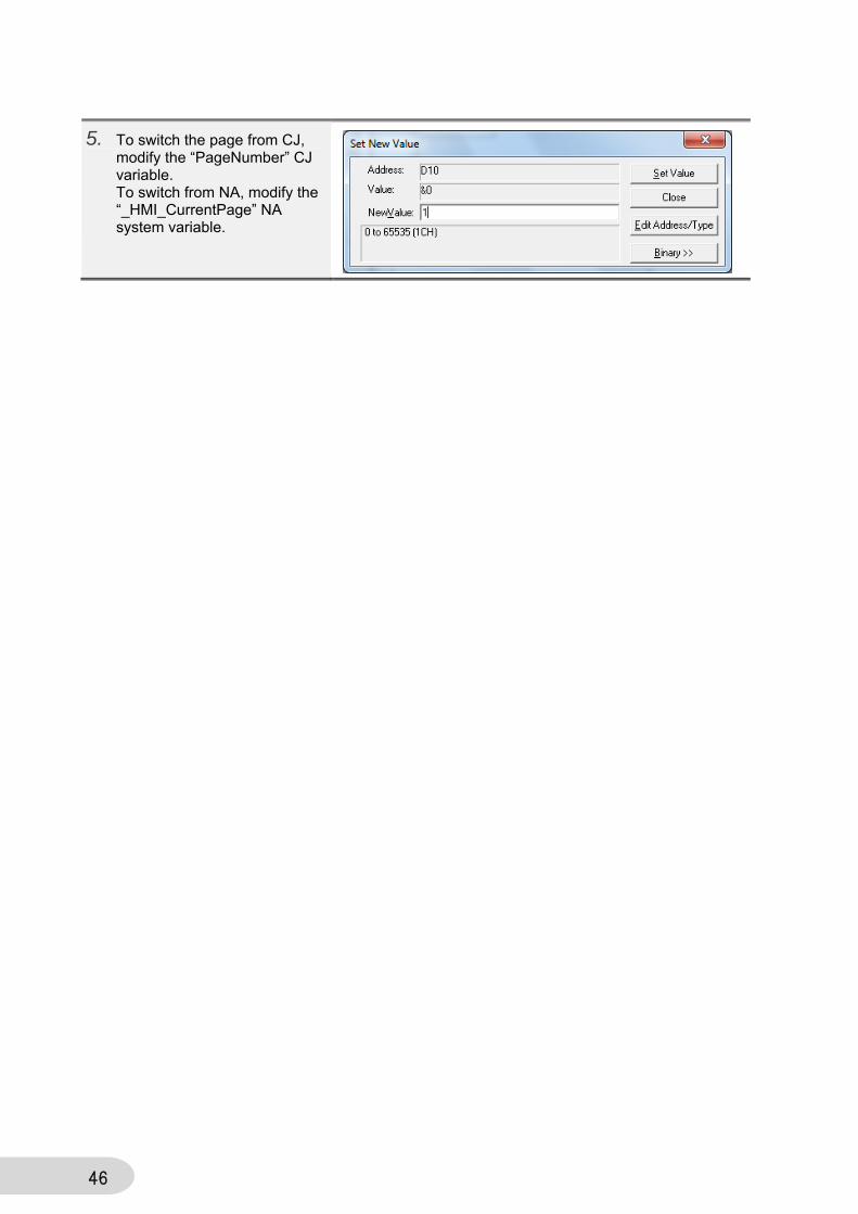
5. To switch the page from CJ, modify the “PageNumber” CJ variable. To switch from NA, modify the “_HMI_CurrentPage” NA system variable.

47
3 Revision History Revision Code Date Revised content
A July 2015 Original production
OMRON CANADA, INC. • HEAD OFFICEToronto, ON, Canada • 416.286.6465 • 866.986.6766 • www.omron247.com
OMRON ELECTRONICS DE MEXICO • HEAD OFFICEMéxico DF • 52.55.59.01.43.00 • 01-800-226-6766 • [email protected]
OMRON ELECTRONICS DE MEXICO • SALES OFFICEApodaca, N.L. • 52.81.11.56.99.20 • 01-800-226-6766 • [email protected]
OMRON ELETRÔNICA DO BRASIL LTDA • HEAD OFFICESão Paulo, SP, Brasil • 55.11.2101.6300 • www.omron.com.br
OMRON ARGENTINA • SALES OFFICECono Sur • 54.11.4783.5300
OMRON CHILE • SALES OFFICESantiago • 56.9.9917.3920
OTHER OMRON LATIN AMERICA SALES54.11.4783.5300
Authorized Distributor:
V422-E1-01 07/15 Note: Specifications are subject to change. © 2015 Omron Electronics LLC Printed in U.S.A.
Printed on recycled paper.
Automation Control Systems• Machine Automation Controllers (MAC) • Programmable Controllers (PLC) • Operator interfaces (HMI) • Distributed I/O • Software
Drives & Motion Controls • Servo & AC Drives • Motion Controllers & Encoders
Temperature & Process Controllers • Single and Multi-loop Controllers
Sensors & Vision• Proximity Sensors • Photoelectric Sensors • Fiber-Optic Sensors• Amplified Photomicrosensors • Measurement Sensors• Ultrasonic Sensors • Vision Sensors
Industrial Components • RFID/Code Readers • Relays • Pushbuttons & Indicators• Limit and Basic Switches • Timers • Counters • Metering Devices • Power Supplies
Safety • Laser Scanners • Safety Mats • Edges and Bumpers • Programmable Safety
Controllers • Light Curtains • Safety Relays • Safety Interlock Switches
OMRON AUTOMATION AND SAFETY • THE AMERICAS HEADQUARTERS • Chicago, IL USA • 847.843.7900 • 800.556.6766 • www.omron247.com
OMRON EUROPE B.V. • Wegalaan 67-69, NL-2132 JD, Hoofddorp, The Netherlands. • +31 (0) 23 568 13 00 • www.industrial.omron.eu
![NA-series HMI [Programmable Termina]l Device Connection ... · The basic information required to use an NA-series PT is provided in the following three manuals. ... 1.6 to 6.0 mm](https://img.pdfslide.us/doc/110x75/5cfd337288c993f90b8d3f94/na-series-hmi-programmable-terminal-device-connection-the-basic-information.jpg)