Embed Size (px)
Citation preview

N93-B2111
SATELLITE TEST ASSISTANT ROBOT (STAR) 1
D. A. McAffee 2D. J. Kerrisk3
K. R. Johnson3
Jet Propulsion LaboratoryPasadena, California
ABSTRACT
A three-year, three-phase program to demonstrate the applicability of telerobotictechnology to the testing of satellites and other spacecraft has been initiated.Specifically, the objectives are to design, fabricate, and install into the JPL 25-ft.Space Simulator (SS) a system that will provide the capability to view testarticles from all directions in both the visible and infrared (IR) spectral regions, toautomatically map the solar flux intensity over the entire work volume of thechamber, and to provide the capability for leak detection.
The first year's work, which provides a vertically mobile viewing platformequipped with stereo cameras, will be discussed. Design constraints and systemimplementation approaches mandated by the requirements of thermal vacuumoperation will be emphasized.
INTRODUCTION
Telerobotics in the general domain of space applications has had a difficult timein attracting the support of a user community. This is not surprising; flight systemmanagers tend to be very conservative technologically, and rightly so. No flightsystem manager is likely to be willing to put at hazard his budget and schedule inorder to incorporate into his program new and unproven technologies that are notessential to his primary mission objectives.
To break this impasse, it will be necessary for spacecraft program managers tosee the capabilities of telerobotics in action, and to be able to judge the maturityof the technology, in a non-threatening environment. One such environment thatcould have high visibility to spacecraft managers, but still be non-threatening, isspacecraft testing.
1 This paper presentsone aspectof the workcarriedout by the Jet Propulsion Laboratory for theNationalAeronauticsandSpace Administration2 Member ofthe TechnicalStaff3 TechnicalGroupSupervisor
131
https://ntrs.nasa.gov/search.jsp?R=19930022922 2020-04-06T03:49:25+00:00Z

The STAR program was devised to fill an observed need (for a greater degree ofautomation and more flexibility) in the spacecraft testing arena. It was proposedto Code R as a joint effort between the telerobotics technologists and thoseresponsible for spacecraft testing, as a means for introducing technologydeveloped under the aegis of the Telerobotics Program into a flight programenvironment in a manner that would be non-threatening to flight articles. At thesame time it presented to the Code R program the challenge of designing to anenvironment close to that of space. The emphasis in the program therefore is onthe detailed engineering required to adapt known technology to the harshenvironment of space. It is the flavor of that detailed engineering that this paper
attempts to convey.
GROUND RULES
The two ground rules that guided the conception of the program were:
(1) the effort should showcase technology developed by Code R as part of theTelerobotics Program; and
(2) the product should be sufficiently attractive and non-threatening to the usercommunity that they would be willing to incorporate it into their test plans.
To satisfy these ground rules a joint effort was initiated between the teleroboticstechnologists and the spacecraft test engineers to identify those needs that mightbest be met by telerobotics technology. An obvious target was test operations inthe large space simulators in which spacecraft system testing is conducted. Here,where the test article is inaccessible during test, and where gaining access to thetest article is both expensive and time-consuming, it seemed that telerobotictechniques could prove valuable in assisting the test operations. A crude estimateindicated test cost savings of a quarter of a million dollars per year might beanticipated. One major constraint was immediately recognized, however: nothing(and certainly no robotic element) would be allowed to penetrate the work volumeof any spacecraft while it was in the chamber. Thus, any assistance during testoperations would be limited to remote sensing. Even with this constraint,however, there were immediately identified a number of functions thattelerobotics-developed technology might supply.
Remote observation- direct observation of test articles is extremely limited.In order to provide a uniform thermal background, thenumber and size of observation ports in the two majorJPL test chambers has been kept to a minimum, andthe viewing angles available are far from ideal. Thishas been somewhat compensated in recent years bycameras mounted in the chamber, but these havebeen in fixed locations. The ability to observe the testarticle from all angles, at varying degrees of
132

magnification, and in stereo, was identified as a highlydesirable capability to have.
Remote temperature sensing- presently spacecraft are instrumented withhundreds of thermocouples to provide verification ofthermal models. If an IR camera could be mounted to
provide viewing of the test article from any and allangles, a great deal more data could be generatedwith a great deal less effort. IR sensing of the testarticle from the movable pan/tilt platform was alsoidentified as a desirable capability.
Solar intensity mapping- obtaining a map of solar intensity throughout thechamber is a cumbersome and laborious process aspresently implemented. Automation of thismeasurement, which is carried out generally onlywhen no test article is present, would be anotherdesirable feature for any system to be installed in thechamber.
Leak detection- pinpointing leaks in the shroud when they occur is avery difficult and time-consuming task, involving goingover the surface with helium leak detectors. Anyautomation of this function, which would result inreduction of chamber down-time, would be veryuseful. It was estimated that this alone could save$120,000 per year.
Having identified a list of potential functions, a design concept for a system toprovide those functions was generated, and is shown in Figure 1. A program wasthen outlined that would allow a phased development of capability, withcheckpoints along the way that would allow periodic reevaluation of bothobjectives and progress. Providing users with an early demonstration of thepotential advantages of the technology was an important aspect of the program,which was proposed in three phases:
Phase 1- FY '92- Demonstrate in the JPL 10-ft SS an improved viewingcapability with a Z-axis-movable pan/tilt platform on which astereo vision system is mounted. (Because of previouslyscheduled modifications, the 25-ft SS will not be available forSTAR installation until the end of FY 93.)
Phase 2- FY '93- Install the system into the 25-ft SS, and add the IR cameraand the solar spot mapping capability.
Phase 3- FY '94- Add capability for azimuthal motion of the platform, and leakdetection capbility.
This paper presents the Phase 1 effort.
133

:.:.-.
_ i!::"' .....S:::"
TOP AZIMUTHAL
js..ooo /% _;_
IIi
!
STEREO CAMERAS WITHINFRARED'CAMERA ONPAN TILT PLATFORM
_LUX
\ MEASUREMENT\ DEVICEI_2 DOF ROBOTIC ARM
(REMOVEABLE)
BOTrOM
AZIMUTHAL"
RAIL
J
Figure 1. Initial Concept for the STAR System
134

MAJOR DESIGN CONSIDERATIONS
The basic concept for the system as outlined above is quite straightforward.Complications quickly arise however when specific requirements related to theapplication are taken into consideration. First and foremost of these is theenvironment in which the system will have to operate.
For STAR, the application environment includes high vacuum, i.e., on the order of
10 -7 torr, and temperatures ranging from -196 ° C to +93°C. (It should be notedhere that for the Phase 1 demonstration there will be no cold shroud in the 10-ft
SS. However, since the same hardware is to be ultimately installed in the 25-ftSS, the design temperature range must accommodate that application.) Hardvacuum operation imposes stringent cleanliness requirements, since nosignificant outgassing can be tolerated, both in terms of maintaining vacuum, andin avoiding contamination of the test article. Further, rubbing surfaces are to beavoided, since they tend to produce particulates which can then deposit onsensitive surfaces. The large temperature range means that there will besignificant dimensional changes in all components; these changes will of coursebe a function of the materials used. The design must address theseconsiderations in detail.
Another important design consideration for this application is that the systemmust not significantly disturb the environment seen by the test article, as, forexample, by presenting a warm spot in the otherwise uniformly cold wallsurrounding the test article, or by presenting a source of glare that might confusespacecraft optical components. This means that all heat sources, such as thedrive motors, or cables that are dissipating heat, must be shrouded from thedirect view of the test article. By the same token, shiny surfaces are not desired.The design must recognize these constraints.
A third design consideration is reliability and ease of maintenance. Since one ofthe major drivers for this program is the promise of decreasing the amount of
• down-time in testing, it would be counterproductive to have to halt testing torepair this equipment, or, when repairs or maintenance are required, to make itso awkward or time consuming to accomplish them as to defeat the purpose ofinstalling the system in the first place.
A consideration notable for its absence from this list is extreme accuracy. Unlikemost robotic applications, positional accuracy is not a strong requirement for theSTAR system. To have position knowledge and repeatability accurate within acentimeter or two was judged to be quite adequate for this application. Since thisis well within the capabilities of even the crudest mechanization, it was not adriver in the design.
135
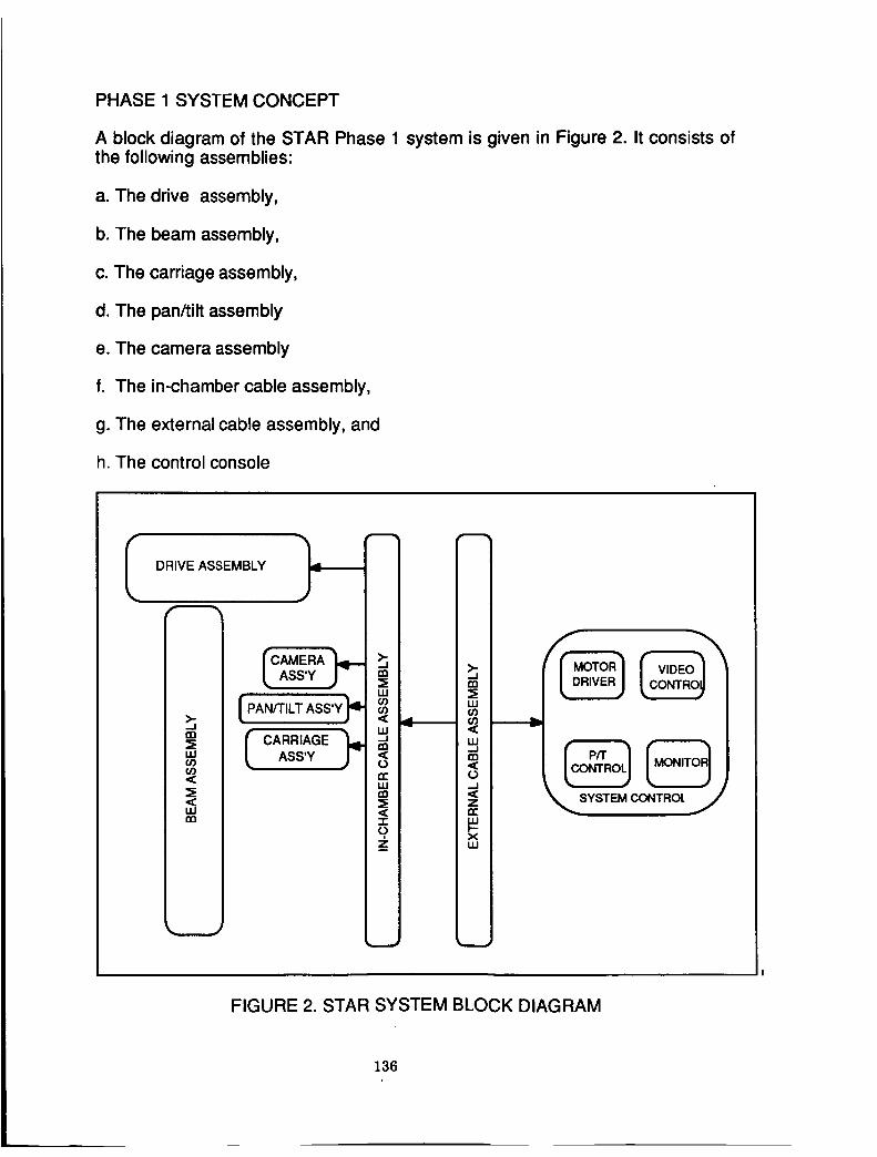
PHASE 1 SYSTEM CONCEPT
A block diagram of the STAR Phase 1 system is given in Figure 2. It consists ofthe following assemblies:
a. The drive assembly,
b. The beam assembly,
c. The carriage assembly,
d. The pan/tilt assembly
e. The camera assembly
f. The in-chamber cable assembly,
g. The external cable assembly, and
h. The control console
I DRIVE ASSEMBLY f
>-._1rn
UJO0O0
LU
CAMERA ;"),-
CARRIAGE _oASS'Y
rr I
_zl
...1IXl
W
W....Im
0
-.I
Zn"
XU.I
FIGURE 2. STAR SYSTEM BLOCK DIAGRAM
136

Table I
Comparison of Candidate Ddve Mechanisms
NIZATION
CHARACTERISTIC
A. MATERIALS
RACK
AND
PINION
LEAD/BALLSCREW
CHAIN
DRIVECABLE
DRIVEMETAL BELT
DRIVE
Properties at Cryo Tempe 3 3 4 2 1
Properties over Wide Temp Range 4 4 4 2 1
Vacuum Rated 2 2 4 4 1
Non-Outgassing
Availability (Stock or G,istom Comp)
Overall Mass
Comparitive Reliability
Est. Development Time
Simplicity of Assembly/Install.
3
4
Maintainability
Overall Cost
B. CLEANLINESS
Lubrication Required 4 4 4 1 1
Rubbing vs. Rolling Contact 3 4 4 3 1
Ease of Cleaning 3 4 4 5 1
Debris Generation 3 3 4 3 1
1i BEST SELECTION
Rail/Linear Bearing
Open Belt
Electrical Cable Spool
Pulley Diameter
Roller Diameter
Counter-Balanced
5I WORST SELECTIOt
Table II
Major Design Analyses Conducted
Beam/Roller
Closed Belt
Rolling Loop
Belt Stressvs
Belt Width
Belt Thickness
Hertzian Contact Stress
Non-Counter-Balanced
137

For each of these assemblies a number of design approaches were available;space does not allow a discussion of them all. In the following paragraphs themost significant design choices will be presented, with an indication of therationale behind the choice. Emphasis is given to the in-chamber portion of thesystem, since that external to the chamber (external cabling and control console)presented no special design problems.
DESIGN DESCRIPTION
a. Drive Assembly
The drive mechanism is the heart of the design, and was the most difficult todesign within the constraints imposed by the environment. Its design also drovethe design of most of the other system assemblies. It will serve as an example ofthe kinds of analyses that were required to validate the detail design.
For the Phase 1 effort the final product is to be a vertically moving carriage onwhich will be mounted a pan/tilt platform. Any number of options were available toprovide the vertical motion, including rack-and pinion, cable, chain, lead or ballscrew, metal belt/pulley, etc. Each of these has its own peculiar advantages anddisadvantages. Some of the most obvious are listed in Table I for variouscandidate mechanizations. Scanning Table I, and in light of the designconsiderations given above, the metal belt/pulley system appeared to provide thebest match for the requirements. It is compatible with the design requirements ofvacuum operability over an extreme temperature range and high cleanliness, it ispotentially lightest in weight, and the simplicity of the concept makes itsimplementation appear reasonably economical. With little time to pursue in-depthtrade-off studies, this approach was selected early as the baseline for STAR.Emphasis then shifted to the next layer of questions, i.e., what would it take tomake it work. Questions of materials selection, accommodation for thermalexpansion/contraction, unlubricated operation, avoidance of sliding contacts,cable accomodation, etc., required addressing in detail.
Table II lists some of the more significant design analyses required to come upup with a design that would meet all requirements. A detailed exposition of all thetrade studies performed is beyond the scope of this paper; only the highlights andmajor conclusions will be reported here.
Drive Train
The selected motor is an Inland Brushless DC motor, Model RBE04500, flightand vacuum rated at 1000 in-oz of torque and for -55°C operation. It wasselected specifically because it is designed for vacuum operation. A worm geardrive was selected because of its inherent non-backdriveability; while it violatesthe design criterion of no rubbing contacts, the rule was violated in this one casebecause it provided the additional advantages of a high gear ratio and smoothoperation. The selection of materials (bronze for the worm gear and steel for the
138

drive gear) should minimize particulates generated by the rubbing motion. Evenso, the drive will be totally enclosed in a housing to minimize the potentialcontamination that might be generated by this gearing.
Belt and Pulley
A primary concern was the selection of a belt material that could withstand the
extremes of temperature and maintain high strength without embrittlement. Anassociated question was the diameter of the pulley, to minimize the bendingstresses on the belt without violating the constraints of the maximum envelopeallowed for the mechanism. Only solid belts were considered; woven belts,though far more amenable to the temperature extremes, were rejected becausetheir (huge) surface areas posed too great a threat for contamination.
A survey of belt manufacturers uncovered no one who was willing to certify theirbelts for the specific environment we specified. However consultation withmetallurgists indicated semi-hard 304 stainless steel should have the desired
characteristics. A quick (though not highly scientific) test program involvingflexing 304 stainless steel belts in liquid nitrogen and examining them for cracksverified this choice, which became the baseline. A further series of analyses onbending stress and yield strength as a function of bend radius and belt thicknessled to the design parameter selection shown in Table III, which provides a designmargin of about a factor of four for the maximum anticipated load of 100 Ibs.However, to provide redundancy and an added margin of safety, a two beltsystem has been baselined.
TABLE III
Metal Belt Parameters
BELT LENGTH
BELT WIDTH
BELT THICKNESS
BELT MATERIAL
FATIGUE STRENGTH(I00,000 CYCLES)
TENSILE STRENGTH
BELT CYCLIC LOAD CAP
BELT STATIC LOAD CAP
320 1NCHES
2 I NCHES
0.008 INCHES
304 SS COLD-WORKED
1/2 HARD
1 15,000 PSI @ 20"C
155,000 PSI @ -196"C
195,000 PSI @ 20"C260,000 PSI @ -196°C
1400 LBS @ 20"C
3100 LBS @ 20°C
139

A final design decision was made to leave the belts open-ended. Thisautomatically maintains belt tension as thermal expansion and contractionchanges belt length, without the need for additional tensioning devices.
The baselined pulley/drive train system is shown in Figure 3, and, as an explodedview, in Figure 4. Figure 5 is a photograph of the actual hardware after initialassembly.
b. Beam Assembly
The selection of a belt and pulley drive allows the use of a simple andinexpensive U-beam for the vertical member. The beam is supported at the toponly; the bottom is pinned via slotted holes to allow for thermal motion whilemaintaining verticality. The selected beam is 4 in. by 12 in., 6061-T6 aluminum,with 0.29 in. wall-thickness, black anodized, and for the initial demonstration is 25feet long. Nothing in the design limits the beam to this length, however, and thebasic design is fully adaptable to the larger 25' space simulator by using a longerbeam.
The beam assembly is shown in Figure 6. The depth of the beam has beenchosen to comfortably house the rolling loop cable that supplies power and signalconnections to the carriage. A cover, split to allow passage of the wiring, isprovided to shield the wiring from the chamber and to present to the chamber asuniform a temperature environment as possible.
c. Carriage Assembly
The primary design challenge for the carriage assembly was to provide freemot;on with minimum friction and no binding over the large temperature rangeand in high vacuum. As noted earlier, this eliminated from consideration anydesign that requires sliding contacts. The selected design, shown in Figure 7,provides six sets of wheels. Two sets (top rear and lower front) are load-bearing,while a second set (top front and lower rear) are spring loaded to assure contactis maintained. An additional set of wheels, also spring-loaded, is mounted to eachside to maintain alignment as the beam changes dimensions during thermalcycling. Vespel has been selected as the wheel material to minimize thepossibility of contamination by metal particulates that might be generated fromthe rolling contact of the wheels with the beam. Bearings are 440C stainlesssteel, and are unlubricated.
A major feature of the carriage is the ease with which the assembly can beremoved. Loosening four bolts that secure the wheel assemblies, unfasteningthree electrical connectors, and pulling a single release pin from the belt yokeallows the entire carriage and instrument payload to be lifted off as a unit.
d. Pan/Tilt Platform
A pan/tilt platform previously used in the space simulator was available for atleast temporary use with this system. This platform is shown in Figure 8.
140

Figure 3. Perspective View of the Drive Assembly
Figure 4. Exploded View of the Drive Assembly
141

Figure 5. The Drive Assembly Hardware
Figure 6. The Beam Assembly
142

Figure 7. The Carriage Assembly
Figure 8. The Panmilt Platform
143

e. Camera Assembly
The capability to be demonstrated in STAR Phase 1 is stereo viewing of the testarticle. To provide useful stereo over a reasonable range of target distances fromthe cameras, and to provide close-in viewing when required, a three cameraarrangement, as shown schematically in Figure 9, taken from Ref 1, has beenselected. The salient parameters for the camera arrangement for the Phase 1demonstration are given in Table IV, also taken from Ref. 1. The camerasselected are designed to be vacuum operable, and will operate at temperaturesas low as -50°C. To maintain them at this temperature will require thermal
blanketing.
Cameras 1 and 2 have identical fixed focal length lenses, with manually
adjustable focal distances. For any given test, these will be fixed prior to chamberevacuation. Camera 3's lens will be remotely adjustable for focal distance, andwill serve as the best focused lens for both near and far stereo viewing.
The system will allow monocular camera viewing by any camera, andstereoscopic viewing by any pair of cameras. The video switcher will allow anycamera image to be viewed on any of the three monitors.
A comprehensive discussion of the stereo system design process used here canbe found in Ref. 2.
Table IV
Camera Configuration Parameters for the 10' Simulator
CAMERA PAIR
1.3
INTER-CAMERADISTANCE
5.6 INCHES
2.5 INCHES
3.1 INCHES
MONITOR
# DIAG.SIZE
1 16"
2 22"
3 20"
CONVERGENCEDISTANCE
2.2 METERS
1.6 METERS
3.0 METERS
144

Y 3,0meters
2.2meters
ZOOM_LENS
PLATFORM
I
I VIDEO SYNC
GENERATOR
I STEREO TVMIXER
v,oEo, iMON'TORI ! MON'TORII1' ' IMONITOR3
r _ STEREO GOGGLES
Figure 9. Camera Arrangement for the 10' Simulator
145

f. In-Chamber Cable Assembly
The overall schematic of the in-chamber cabling is shown in Figure 10. The onlysignificant question here was the selection of cables for connecting the carriageand its payload to the chamber feed-throughs. To accommodate the motion ofthe carriage a rolling loop is employed. The cable, which is laid inside the beam,may reach temperatures close to -196°C. Again, no manufacturer was willing toguarantee the integrity of insulation flexing at such temperatures. Tests were run,flexing various flat cables with insulation rated for vacuum operation in a liquidnitrogen bath. In this testing, teflon insulated cables proved to have quitesatisfactory flexing properties at LN2 temperatures, and are being used for all in-chamber cables.
g. External Wiring Assembly
The external wiring poses no particular problem, and is mentioned here only forcompleteness. The external cabling is shown schematically in Figure 11.
h. Control
A 386 microprocessor is being built into the STAR system even though therequirements of the Phase 1 demonstration could be satisfied with a far lesscapable controller. The controls for the Phase 1 demonstration are relativelysimple: vertical position commands are given via keyboard input and the motorencoder provides the necessary position feedback. Software limits areincorporated, and are backed up by mechanical limit switches. The pan/tilt unit isrun on the same principle. The focal length of the lens system on camera 3 iscontrolled open-loop by the operator.
Later phases of the program will see more complex control loops incorporated.
STATUS
Table V summarizes the status of each of the assemblies of the STAR system;the present schedule calls for the system to be installed in the 10-ft SS by theend of August, and for the first full-up demonstration of the system by the end ofSeptember.
REFERENCES
. Diner, D.B. "Stereo Viewing Sy_em for STAR"JPLIOM 3474-92-059,June 30,1992
2. Diner, D. B., and D. H. Fender "Human Engineering in StereoscopicViewing Devices" JPL Report #D-8186, January 15, 1991
146

DUFFERDOX
LIMIT SW
UPPER POS REF
CENTER 1:105 FIEF
LOWER 1:105 FIEF
LIMIT 5W
[][]
[][][][]
CHAMBER
WALL
Figure 10. Schematic of the Internal Cabling Assembly
oox 0qMOTOR
DR I VEIl
I STEREOMIXER
I
VIDEOSWITCHER
__ _ I'IONITOR_
_ HONITOR _
MONITOR
I 1,2v°clPAN AND PSTILT DRI VER
I INTERFACE BOX
COMPUTER
r'-'---i _
IFigure 11. Schematic for the External Cable Configuration
147

Table V
Status Summary
Drive
Drive Motor
Carriage
Beam
Pan/Tilt
Cameras
Internal
Cabling
Detail
Design/Proc.
Spec.
Complete
Complete
Complete
Complete
Complete
Complete
Complete
Fabricate
Procure
Complete
Placed
,In Process
Complete
Existing
Placed
In Process
Deliver
Complete
Due
Aug 14
Due
July 3 1
Complete
Due
Aug.3
Due
Aug 15
External
Cabling
Control
Console
Complete
n Process
n ProcessDue
Sept. 1
Due
Sept. 1
Assemble/
Checkout
Complete
Complete
Complete
148


![N93-1 CHAPTER 9NO as NO2 [46] 9.3(6-19) 14.4 (6-19) Depends on design (5-45) *Mean (fuel-consumption weighted) emission indices for 1987 based on Boeing (1990). The values were cal-culated](https://img.pdfslide.us/doc/110x75/60a05c08e64e8c1b000380bd/n93-1-chapter-9-no-as-no2-46-936-19-144-6-19-depends-on-design-5-45-mean.jpg)