Embed Size (px)
Citation preview

N91-27
STRUCTURAL CONCEPT STUDIES FORA HORIZONTAL CYLINDRICAL LUNAR HABITAT
AND
A LUNAR GUYED TOWER
Prepared by:
Academic Rank:
Final Report
NASA/ASEE Summer Faculty Fellowship Program - 1990
Johnson Space Center
Paul K. Yin, Ph.D.,P.E.
Associate Professor
University and Department: U.S. Coast Guard Academy
Engineering DepartmentNew London, Conn. 06320
NASA/JSC
Directorate: Engineering
Division: Systems Engineering
Branch: Systems Definition
JSC Colleague: Clarence Bell, Ph.D.
Date Submitted: August I0, 1990
Contract Number: NGT-44-005-803
28-1
https://ntrs.nasa.gov/search.jsp?R=19910017803 2020-05-10T05:17:49+00:00Z

ABSTRACT
A conceptual structural design of a horizontal
cylindrical lunar habitat is presented. The design includes
the interior floor framing, the exterior support structure,the foundation mat, and the radiation shielding. Particular
attention has been given on its efficiency in shipping andfield erection, and on selection of structural materials.
Presented also is a conceptual design of a 2000-foot
lunar guyed tower. A special field erection scheme is
implemented in the design. In order to analyze the over-all
column buckling of the mast, where its axial compression
includes its own body weight, a simple numerical procedure isformulated in a form ready for coding in FORTRAN. Selection of
structural materials, effect of temperature variations,
dynamic response of the tower to moonquake, and guy anchoringsystem are discussed.
Proposed field erection concepts for the habitat and forthe guyed tower are described.
INTRODUCTION
The Systems Engineering Division of the NASA/JSC is
studying the development of permanent human presence on the
moon. The development includes a relatively large habitat toprovide long term human habitation, antenna towers for
communication, among others.
The author designed the internal framing and the external
foundation for a spherical inflatable lunar habitat during thesummer of 1989 (A concept developed within NASA/JSC) [1,2].
With the experience gained on the first design, the Systems
Engineering Division is considering a horizontal cylindrical
habitat in addition to a spherical one. A conceptual
structural design of this second concept (excluding the
inflatable air enclosure) is presented in this report. The
structure was analyzed by Ed Robertson of Systems EngineeringDivision, Systems Definition Branch using SDRC's IDEAS program[3]. An order-of-magnitude estimate of total structural dead
weight is presented. The estimate is based on the structural
members of Aluminum Lithium 8090-T8771 for the inside of the
habitat and Magnesium alloy ZCM 711 [4] for the outside of the
habitat, all within the AISC stress limitations [6] under the
specified design live loads. The architectural and functional
requirements including design live loads were provided by K.
J. Kennedy of the Systems Engineering Division. The interior
and exterior structural framings are to be pre-assembled,
packaged for shipping, and automatically deployed into its
final installed configuration with minimum effort required for
28-2

field assemblage.
The development of permanent human presence on the moon
also includes systems which may require installations of tower
structures. Such systems may be for the lunar surface
communication, power transmission, and area illumination.Given the radius of the lunar sphere the height of the towers
is dictated by the distance between two adjacent towers. The
longer the distance between towers, the higher the towers mustbe. While the communication area covered by a tower increases
with the square of the tower's height the structural dead
weight increases, generally speaking, with the cubic of the
tower's height. This implies that the optimum height of thetower for lunar surface communication is zero. Further trade-
off study on the use of towers for communication to the farside of the moon is needed including other factors and other
possible alternatives.
For a surface area on the moon covered by a 30-mile
radius (a limitation on an un-pressurized lunar rover) the
height of the tower is approximately 2000 feet. A conceptual
design of a 2000-foot lunar guyed tower, its materials, andfield erection scheme are presented.
The installation of a 2000-foot guyed tower on the
surface of the moon represents some unique designconsiderations. These considerations were studied and are
discussed in this report.
THE HABITAT
General Concept
The basic concept of the horizontal cylindrical lunarhabitat is similar to that of the spherical inflatable lunarhabitat studied in the summer of 1989 [1,2] except that the
over-all shape of the inflatable air enclosure is horizontal
cylindrical, the regolith shielding is self supporting, the
site preparation involves the removal of only the first one-foot layer of the lunar surface soil, and the framing is more
efficient for shipping and field erection (Figure I).
Desian Requirements
The requirements, objectives and constraints are:
i. A minimized total structural dead weight.
2. Satisfaction of the Specification for the Desian,
Fabrication° and Erection of Structural Steel for
(AISC) [6].
3. Efficient for shipping and field erection.
28-3

4. A design live load of 50 earth pound per square foot
(2.40 kPa) for the upper floor and I00 earth pound per
square foot (4.79 kPa) for the lower floor (from K. J.
Kennedy, Systems Engineering Division, JSC).
5. Architectural requirements as given by K.J. Kennedy of
the Systems Engineering Division (Figure i).
Interior Structural Framing
A highly efficient flat space truss (a pallet, developed
by the Structural Engineering Division of JSC [12]) wasdetermined to be suitable for both the two interior floors.
The truss can collapse into a highly compact bundle for
shipping and be automatically deployed into its final
configuration at the site. The interior floor trusses for
both the two levels (Figure i) are about one-foot deep and are
composed of 0.394-inch (l-cm) diameter round bars of Aluminum
Lithium 8090-T8771 all of equal length for the upper and the
lower cord planes and the 0.315-inch (0.8-cm) web members.Each floor truss is supported at ten points through which the
area live loading is transferred across the fabric to the
exterior support framing (Figure I).
Exterior Support Structure
The support structure outside the habitat is designed so
that the structure can be retracted into a bundle for shipping
with its length slightly greater than the diameter of the
cylindrical air enclosure (Figure i).
The interior floor trusses and the exterior support
structure were analyzed by Ed Robertson of the Systems
Engineering Division, JSC using SDRC's IDEAS [3]. Under the
design live loads, the maximum stresses and deflections wereall found within AISC's limitations [6].
The foundation mat provides enough bearing area for a
factor of safety of 4 against ultimate bearing capacity of the
lunar soil at about one-foot depth based on the lunar soil
properties given by Mitchell, et.al. [7] using an empiricalformula by Vesic [8]. The mat is designed so that it can be
rolled into a bundle for shipping (Figure i). The site
preparation requires removal of the first one-foot layer ofthe lunar surface soil.
Radiation Shieldina
The radiation shielding is essentially made of flat spacetrusses similar to the floor trusses inside the habitat,
28-4

filled with lunar regolith, and each is wrapped with fabric to
contain the regolith (Figure i).
Aluminum Lithium 8090-T8771 is proposed for the interior
floor trusses for its superior strength-to-weight ratio. Its
relevant properties at room temperature are: [4,5]
Ultimate Strength:
Yield Strength:
Percent Elongation:
Mass Density:Modulus of Elasticity:
Thermal Expansion Coeff.:
64 ksi (441.28 MPa)
50 ksi (344.75 MPa).5 to 2 %
0.091 ibm/in 3 (2,519 kg/m 3)
ll.7x106 psi (80,672 MPa)13x10-6/OF (23xi0-6/oc)
Magnesium alloy ZCM 711, high in its strength-to-weightratio, is selected for the exterior support structure and thefoundation mat. This material has a relatively low combustion
temperature and therefore is unsafe to use inside the habitat
where oxygen is present. The relevant properties of this
material are: [4,5]
Ultimate Strength:
Yield Strength:Percent Elongation:
Mass Density:Modulus of Elasticity:
Thermal Expansion Coeff.:
40 ksi (275 MPa)
27 ksi (185 MPa)12 %
0.065 ibm/in 3 (1,795 kg/m 3)
6,500 ksi (45 GPa)15x10-6/OF (27xi0-6/oC)
Structural Dead Weight
The following weight estimate is based on a very basic
conceptual design and therefore gives only a rough idea of theamount of materials to be shipped to the moon:
Upper Floor Truss: 1,320 ib m ( 600 kg) of AI-Li
Lower Floor Truss: 950 ib m ( 430 kg) of A1-Li
Support Structure: 560 ibm ( 254 kg) of ZCMFoundation Mat: 4,400 ibm (1,995 kg) of ZCM
Total 7,230 ibm (3,280 kg)
The following is a general outline of the field erection
procedure with much further refinement yet to be developed.
I. A flat level surface is prepared at the site after the
removal of the first one-foot layer of the lunar soil.
2. The top horizontal truss for the radiation shielding
(roof)is fully stretched and is resting on the vertical
28-5

trusses (walls) which are not yet fully stretched.
3. The top horizontal truss is raised to its finalelevation by jacking with the vertical trusses (walls)
fully stretched to their final configuration
simultaneously.
4. All fabric bags over the trusses were pre-attached andare now in their fully stretched shapes.
5. All trusses are filled with lunar regolith from top by
a bucket elevator.6. The foundation mat is laid.
7. The habitat module is placed on the mat.
8. The cylindrical air enclosure is inflated to its final
volume while the pre-attached interior floors and the
exterior support frame are also fully stretched to their
final configuration.
D/mmzSSlQn
Aluminum-Lithium AI-Li 8090 is selected for the interior
floor trusses for its superior strength-to-weight ratio to
minimize shipping weight. The strength-to-weight ratio of
Magnesium ZCM 711 is higher than that of AI-Li 8090 but ZCM711 is unsafe to use inside the habitat due to its low
combustion temperature. ZCM 711 is therefore selected for only
the exterior support frame and the mat. Most Magnesium alloys
including ZCM 711 are known to be weak in corrosionresistance. This presents no problem on the moon for there is
no oxygen nor moisture outside the habitat.
While the Aluminum alloy is known to have superior
resistance to embrittlement at low temperature [Ii] the
Magnesium alloy ZCM 711 looses its ductility at low
temperature and is therefore unsuited for load carrying intension. It is therefore chosen for the support structure and
the mat only where materials are primarily under compression.
The thickness of the first layer of the lunar surface
soil to be removed was arbitrary in the design. Generally
speaking, the soil bearing capacity increases with increase in
depth but at the expense of increased site preparation.
THE GUYED TOWER
General Concept
The general concept of the proposed lunar guyed tower is
essentially the same as that of typical guyed towers found on
Earth (Figure 2). Unlike the design of tower structures on
Earth, a lunar guyed tower requires no resistance to lateralwind loads for there is no wind on the moon. The only
significant environmental lateral loading is perhaps due to a
28-6

moonquake. It is possible, however, that significant stressand deformation occur due to severe daily (lunar) temperature
variations. A structural analysis under this thermal loading
(with the gravity loading properly combined) should be
performed after the structure is better defined and a cyclicheat transfer and temperature-time history throughout the
structure is assessed. In an effort to mitigate this
temperature effect two different materials were selected,
i.e., Magnesium alloy for the mast and Aluminum-Lithium forthe guys. This temperature effect is further discussed in a
later part of the report.
Design Requirements
Given below is a list of a very preliminary requirements/
constraints for the design of the lunar guyed tower.
i. A payload of I,i00 ib m (500 kg) at approximately 2,000feet above ground (given by M.L. Roberts, Systems
Engineering Division, JSC).2. A minimized total structural dead weight.
3. Satisfaction of the _pecification for the Design.
Fabrication° and Erection of Structural Steel for
(AISC) [6].
4. Efficient for shipping and field erection.5. Resistant to moonquake.
6. Resistant to daily (lunar) temperature variations.
7. An elevator to the top of the tower.
The mast is composed of identical 9-foot truss sectionsmade of standard tubular members of Magnesium alloy CZM 711.
The three cords and the braces make the cross sectional shape
of the mast an equilateral triangle (Figure 2). The bottom 9-foot truss section is different from the rest (Figure 3) where
larger openings are provided to facilitate traffic to theinterior of the mast.
2/m_gaaa
The use of wire ropes made of Aluminum Lithium 8090 is
proposed for the guy cables. A simple calculation (assuming
uniform temperature variation throughout the mast and the
guys) shows that, for a guy cable making an angle of
approximately 58 degrees with horizontal and having its
thermal expansion coefficient 23/27 of that of the mast [5],stresses induced in the guys and the mast are minimal due to
the diurnal temperature variations. Using the formulas
provided in [16] the maximum and minimum temperatures are
approximately 240°F (388°K) and -248°F (II8°K) respectively
28-7

(depending also on the location on the lunar surface). These
temperature extremes corresponds to a temperature range of487OF (270°K) [16]. Since the metal tower is more reflective
than the lunar surface the above temperature variation of the
lunar surface can be used as the upper and lower bounds of
temperature variation of the tower structure.
Since there is no lateral wind load on the lunar surface
vertical locations of upper guy connections are determined
solely by the buckling consideration of the mast. Thus the
vertical spacings for the upper guy connections are determined
by the Euler buckling formula [9] with a factor of safety of2, i.e., L = n (EI/2P) 1/2 where P is conservatively taken as
the axial compression at the lower end of the unbraced length
L (the structural dead weight makes the axial compression at
the lower end greater than at the upper end). To include the
effect of the mast's own body weight on its critical buckling
load a numerical procedure was formulated but is not presented
in this report for lack of verification. Published information
on column buckling including the column's own body weight cannot be found at time of this writing [15]. This may be
attributed to its relatively small effect in design (on Earth)
as compared to that due to wind load.
The guys are to be sized to provide a lateral support
capacity at their upper connections equal to 10% of the axialcompression in the mast (to be considered fully effective).
According to a recommended practice [I0], the guys are to be
pretensioned to 1/8 of their breaking strength. Thesepretensions in guys contribute to the axial compression in the
mast (Figure 2).
An equilateral triangular mat is sized to provide a
bearing area at the base of the mast with a factor of safety
of 4 against the ultimate bearing capacity of the lunar soil
at approximately one foot below grade [7,8]. Immediately abovethe mat is a ball joint to effect a hinged support so that
there will be no over-turning moment to be resisted by the
foundation during a moonquake [14] (Figure 3).
All anchors of the guys should provide an ultimate up-
lift capacity based on the breaking strength of the guys. A
safety device is to be installed in series at the lower
connection of each guy. The device should disengage when
tension in the guy reaches a certain fraction of the guy's
breaking strength. Experience in up-lift and lateral load
capacities of piled or coil anchors on lunar surface and theirinstallation is not available at time of this design study.
Estimates of these capacities can be made using some existing
28-8

numerical methods generally available within today's civil
engineering practice. A less efficient alternative for theanchors would be the use of the so-called "deadman" concrete
blocks. This anchoring alternative may become more attractivewhen cast-in-place lunar concrete becomes feasible.
The same Aluminum Lithium 8090-T8771 and Magnesium alloyZCM 711 described earlier in this report for the lunar habitat
are proposed for the guys and the mast respectively.
Structural Dead Weiaht
The total structural mass is estimated at about 9,000 lbmwith the following breakdowns: (excluding payload and anchors)
Mast: 8,620
Guys: 250Pedestal: 160
ibm (3,910 kg) of ZCM
ibm ( 113 kg) of AI-Li
lbm ( 73 kg) of ZCM
Total: 9,_ ibm (4,096 kg)
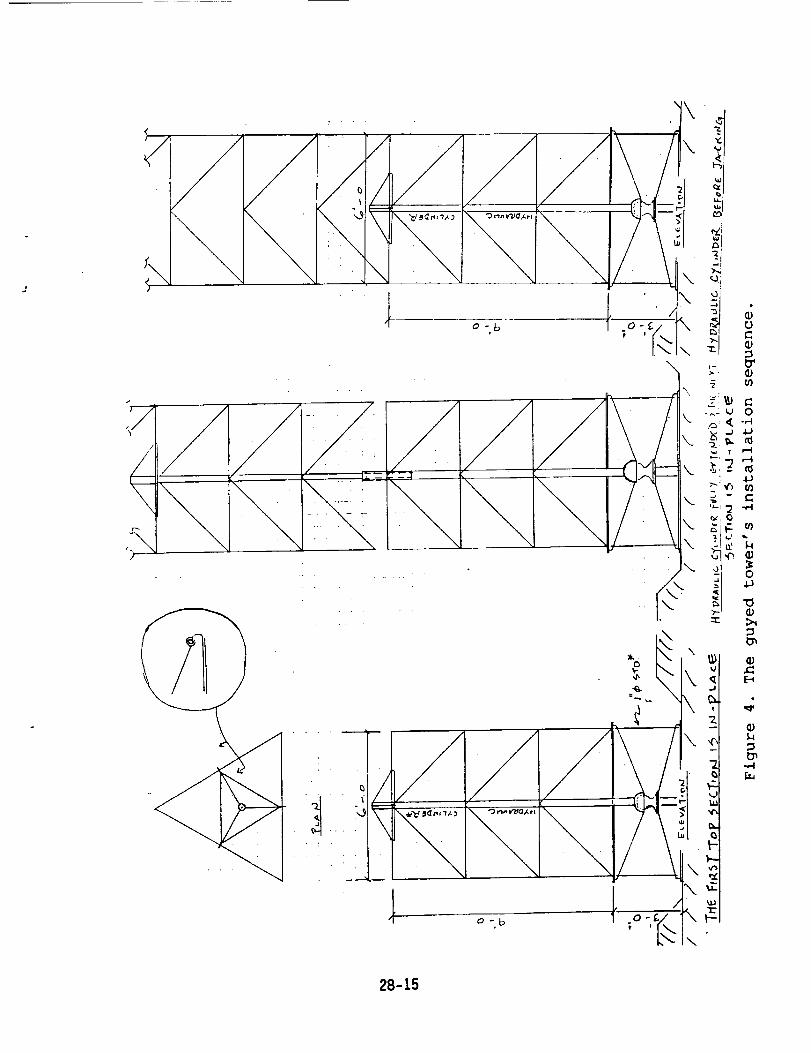
Field
The following field erection scheme for the guyed tower
is proposed (Figure 4).
i. Prepare a flat level surface at the site after removal of
the first one-foot layer of the lunar soil.
2. Set the foundation mat and the hinged-supportassemblage (pedestal) on the prepared surface.
3. Position the top 9-foot section of the mast onto thepedestal.
4. Connect the three top-level guy cables to the top 9-foot section of the mast and to their anchors with some
reels with a controlled tensioning device.
5. Install the hydraulic jack inside the mast.
6. Jack up the top 9-foot section of the mast until itsbottom is clear for the next 9-foot section to be
assembled around the hydraulic jack immediately below.7. Assemble the next 9-foot section.
8. Repeat steps 6 and 7 and connect guy cables as
designed until the last section.9. Assemble the last bottom 9-foot section and secure to
the support pedestal.
I0. Remove the hydraulic jack.Ii. Install the elevator.
12. Remove the three temporary members which were holding
the support pedestal to the foundation mat.
13. Adjust tension in guys for mast's verticality.
28-9

Due to the loss of ductility of the Magnesium alloy ZCM
711 at low temperature, ZCM 711 is selected only for the mast
since the mast is primarily under compression. Aluminum-
Lithium is selected for the guys (in tension) for their known
ductility, modulus of elasticity, and strength preservation at
both high and low temperatures [11,13]. Possibility of
creeping of the mast and guys at the upper temperature extremeshould be studied.
Numerical predictions of capacity and driveability of
piled anchors are well developed for design on Earth.
Applicability of these numerical techniques to lunar surfaces
needs further investigation.
Dynamic amplification and response of the tower to
moonquake should be analyzed and the structural integrity beverified at the two temperature extremes [14,16].
The in-situ guy cables are pretensioned to 1/8 of the
breaking strength of the cable as generally practiced for
guyed towers on Earth [i0]. This pretensioning should be
studied and possibly revised for guy cables on the moon.
Each 9-foot section of the mast can be made collapsible
for shipping, stretched and assembled around the hydraulic
jack at the site.
The daily (lunar) temperature variations of the structure
can be reduced to a certain extent by coating the structurewith some reflective material. The reflective coating reduces
the net solar heat influx and thus lowers the upper extreme of
the temperature variation.
It may be necessary to avoid direct contact between themast (of Magnesium alloy) and the guys (of Aluminum-Lithium)
at the upper guy connections for possible galvanic corrosiondue to the two dissimilar metals.
A constant angle (approx. 60 _) from the horizontal is
proposed for all the guys to mitigate the stresses due to thetemperature variations (in contrast to a single anchor for
each vertical plane of guys, Figure 2)
28-10

REFERENCES
i. Yin, P.K., "A Preliminary Design of Interior Structure and
Foundation of an Inflatable Lunar Habitat," Final Report,
NASA/ASEE Summer Faculty Fellowship Program, Johnson SpaceCenter, 1989.
2. Yin, P.K., "Structural Design of an Inflatable Lunar
Habitat," Engineering. Construction. and Operations in
Proceedings of Space 90, ASCE, 1990.
3. Structural Dynamics Research Corporation (SDRC),
User's Guide. I-DEAS Level 4. Supertab .Engineering_, 1988.
4. Charles, J.A.,Crane, F.A.A., "Candidate Materials for
Aircraft Structures," Selection and Use of Engineering_u_, 2nd Ed., Section 15.4, Butterworths, 1989.
5. Gere, J.M., Timoshenko, S.P., "Mechanical Properties
of Materials," Mechanics of Materials, 2nd Ed., AppendixH,
Brooks/Cole Engineering, 1984.
6. American Institute of Steel Construction, Inc. (AISC),
Manual of Steel Construction, 8th Edition, 1980.
7. Mitchell, J.K. et.al., "Mechanical Properties of LunarSoil: Density, Porosity, Cohesion, and Angle of Internal
Friction," Proceedings of the Third Lunar Science
_, Vol. 3, pp 3235-3253, The M.I.T. Press, 1972.
8. Vesic, A.S., "Bearing Capacity of Shallow
Foundations," Foundation Engineering Handbook, VanNostrand Reinhold Co., 1975.
9. Gere, J.M., Timoshenko, S.P., "Chapter Ii: Columns,"_ of _, 2nd Ed., Brooks/Cole Engineering,1984.
i0. Zar, Max, "Section 24: Towers," Structural Engineering
Handbook, McGraw-Hill Book Company, 1968.
Ii. Glazer, J., et al, "Cryogenic Mechanical Properties ofAI-Cu-Li-Zr Alloy 2090," Presented at the International
Cryogenic Materials Conference, Cambridge, MA, August 12-
16, 1985.
12. Wesselski, C.J., "Expandable Pallet for Space Station
Interface Attachments," U.S. Patent number 4,805,368, Feb.21, 1989.
13. American Society of Metals (ASM), Metals Handbook Desk_, 1985.
14. McCaffrey, R.J., Hartmann, A.J., "Dynamics of GuyedTowers," J. of the Structural Division, Proceedings of the
ASCE, Vol. 98, No. ST6, June, 1972.
15. Goldberg, J.E., Gaunt, J.T., "Stability of Guyed
Towers," J. of Structural Division, Proceedings of the
ASCE, Vol. 99, No. ST4, April, 1973.
16. Binder, Allen, Lunar Data Base, Lockheed Engineering &
Sciences Co. Inc., April, 1990.
28-11

I
//
7,b_
r_
__..,__ - ,I//,. i
•_ . '.. _ _,_,_,_
_'_f -_ "\_\'v_"_v__'_ " I \ l_---._J''L _ :__ L T_
l t ...... _" iITM Z TM 7 TM _ Z_'_" I _.
_ _u D _ ,- i; v A T_ oeo
Figure I. The horizontal cylindrical lunar habitat.
28-12 Om=_m_, PAGE IS
OF POOR QUALITY

.................... . • . • , ....
............. :....... l"_'(....... : " i
• . +_o3...d-c<.... _.
/
.. _ ........ _ ........ _.. _ ._ -g- - _- "_
/
. I'-- (J
I - ]- •
1
\
\\
\
\
" -j •? . _;
"dA..La._S _.i
t
0
C0
-,-I
L)
..,-I
4J
"0
0
"0
d
-,-I
28-13
_ r_:',_,_i. PAGE #$OF POOR QUALITY

¥ _- q.,I
\
i ............ a_-,- .1t r - _ ,f!
r \ I:-\ I\_1 : /:L J ",.._,,,_. _- .... />.
1 °-,_ °-,_ °-,c 1 o._ _:t\
I,d-
4J1,4
Oo_O_
_0
13
O-,-I
4-}
13
O_4
09
0
13
g;2
28-14
or,; _--._r,,,_] .-.,
OF POOR QUALITY
/
J
/
r--
/ '"
i\
_U 0
4J
r__ "-_
4J
Q ", b
0 -£_
\
\
\
k.
k_
\
\
"l
o - b 0 -£ \ _-
\
28-15