Embed Size (px)
Citation preview

"}
: I
~"_ L
N76':'28273
SPACE SHtJITLE TAIL SERVICE MAST CONCEPT VERIFICATION
By Robert T. Uda
Planning Research Corporation
ABSTRACT
Design studies and analyses have been performed to describe the loads and dynamics of the Space Shuttle Tail Service Masts (TSMs). Of particular interest is the motion and interaction of the umbilical carrier plate, lanyard system, vacuum"jacketed (VJ) hoses, latches, links, and masthead (cart). A development test rig was designed and fabricated to obtain experimental data. The test program is designed to (1) verify the theoretical dynamics calculations, (2) prove the soundness of design concepts, and (3) elucidate problem areas (if any) in the design of mechanisms and structural components. This paper describes the design, fabrication, and initiation of TSM development testing at Kennedy Space Center (KSC).
INTRODUCTION
One of the last launch-critical pieces of ground support equipment that will be mated to the Space Shuttle Orbiter vehicle until lift-off is the T-O umbilical. The LHZ umbilical is connected to the left aft end "of the Orbiter, and the LOX umbilical is on the right side. Retracting these umbilicals from the Orbi·· ter's airborne umbilical interfaces and storing them within an enveloping blast housing to protect them from the high temperature environment of the exhaust plumes will be accomplished by two 3Z-foot tall TSMs. Figure 1 shows the two TSMs with relation to the Shuttle vehicle and Mobile Launch Platform.
The present concept involves retracting the T-O umbilicals with the pulling force of a lanyard system connected to and actuated by a free-falling dropweight. Upon releasing the dropweight, the lanyard becomes taut, the collet locks are disengaged, and the umbilical carrier plate is rotated, disengaged, and retracted into the blast housing by a system of cables, flex hoses, and links which are connected to a mast which rotates within the blast housing. The rotating mast triggers the bonnet, which closes an instant after the carrier plate, and all attached equipment and components clear the TSM orifice. This entire process occurs within 1.1 seconds. Figure 2 illustrates the basic TSM operation and components.
JPL Technical Mem.orandum. 33-777 1
https://ntrs.nasa.gov/search.jsp?R=19760021185 2018-06-14T10:34:33+00:00Z

Figure 1.
2
/
~LOX TSM
The two TSMs in relation to the Shuttle vehicle and the Mobile Launch Pla tform
JPL Technical Memorandum 3'1-777

c...., '"d t-'
~ (l)
n ;:r ::s .... . n Pl ~
~ (l)
~ n 0
'"t Pl I '
I I T, I,
U
":;
0-~
8 Vol
EXPLOSIVE Vol I
BOLT , RELEASE
-J -J -J
RETRACT POSITION
Figure 2 . The basic TSM operat ion and components
w

), 4
JUSTIFICATION FOR A CVT PROGRAM
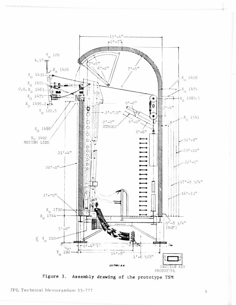
Any redesign and retrofit after prototype fabrication (Figure 3) would be costly to the program in both time and dollars. Results from a development test would increase confidence is concepts and performance prior to committing large sums of procurement funds. Furthermore 1 the probability of redesign and retest later in the program would be greatly reduced, resulting in savings of time and dollars. Therefore, a concept verification test (CVT) program was initiated to design, fabricate, instrument, and test a development test rig at KSC to verify critical TSM design concepts and performance characteristics prior to prototype fabrication. Figure 4 shows the assembly drawing of the CVT rig.
PHYSICAL CONFIGURATION OF THE CVT RIG
~o minimize costs, a structure which simulates only the top portion of the mast was designed and fabricated. Since the masthead traces an arc which is nearly a straight line, the design was simplified to allow the simulated masthead (cart) to translate on horizon~al rails. Furthermore, instead of using a free falling dropweight, a hydraulic actuator was used to simulate the tension force in the lanyards.
Items that were designed included the floor assembly, mount support structure, masthead (cart) 1 lanyard system, links, umbilical carrier plate, plate support assembly, VJ hose brackets, and instrumentation brackets. Off-the-shelf items that were used included the hydraulic actuator, VJ hose, shock absorber (decelerator), and various instruments (e.g., accelerometers, strain gages, potentiometers, load cells, extensometers l pressure transducers, microswitches, oscillograph recorders, high-speed photo-optics, etc.). Figure 5 shows the TSM CVT hardware setup.
DESIGN ANALYSES
The design of the TSM CVT rig was performed in accordance with NASA specifications, standards 1 and guidance documents. References 1-4 are the primary documents used in governing the design. The basic design criteria required that (1) the total weight of the moving assembly (cart/links/VJ hose/lanyard/plate) would not exceed 2268 kg (5000 Ib) and (2) the moving assembly would accelerate at a maximum of 1 g. Sizing and selection of material were based on a safety factor between 3 and 5.
Studies and analyses were performed tp establish design load limits. A static and dynamic link load analysis established the maximum tensile and compressive loads expected (Figure 6).
~, .- " .",..
JPL Technical Memorandum 33-777 'f ..
~-----15 '- "--------~
y 120 o
4.5°1
/ Xo 1426 X 1430
o
X 1455 o e , G, X 1463
o X 1475
o X
o
x o
y o
Xo 1492 , MATING LINE
21 '-4"
20 ' --0"
1 '-' 0"
X 1 7 jc·-!----''''M~~r· r]...J...lIIIMa o X 1744 -4--~~~
o
210
5 ' 0"
y o 14 '-8"
Figure 3, Assembly drawing of the
JPL Technical Memorandum 33-777
1 58
1 80 . )
X 1541 o
31 '-8"
23 '-10"
22 '-5"
17 ' ~9 3/4 "
16 ' - 11"
- ~ 5/8" ~ :tl
SEe'.~ICN KEY PROTOT~'PE
prototype TS~
5

0'
~
t"' 1-1 n ;:r ~ .... n IU ......
$: <Ii
3 o "1 IU ~ 0.. C
3 w W I
..J
..J
..J
ROUNDWf.Y & RAIL INSTALI..ATIOI 'PT'ER SUPPORT SK- MDD- 2- S- 0/1/2217) - 158 SK- MDD- 2 - S- 0- 1/22175- 159, UPPER &. I,OWER LINKAGE
ASSY & DETAILS; QU ICK RELEASE en - ~;K-MDD-2 -S-0-1/9/75 -155- 1): (DfT 2) CABU; ASSY
PIN SK-MD~ 3 2-J-O- 1/9/75- 155)
. ~ . MDD-2- S-0-1/9/75-157- 5 3 ~ i4 tSHT 2 )
1'. : ~CK.1""T 75r1l1501- 1 tJ.) '( BE USED, 2 REQ,D
BEARING , DUAL ROUNDWAY
LINE
ARRANG EMENT
I r FLEX LINE VJ 8 " I 75M09788- 203
MOUNTING BRACKE~ , 7 5M08~ -25-1 SHOCK ABSORBER , 76K30022- 2
, .- SEE SK-MDD-2- S-0-1 /2~1 /7 5 -1f2 \ DETAIL ' B'
- -CYLINDER 7 5M06506- 1
....
L SEE £ BUMPER DETAIL ' A ' '\
'-- SK- MDD-2- S- 0- /22/75- 161 CARRIER PLATE ASSY DETAILS , SHEET 1
\ AC'I'UA'i'OR (
~PULLEY BRONZE McKISSICK 6- 1
I PULLY BRONZE McKISSICK 12--5
2
5K- MDD- 2- S- 0- 1/22/75- 160 u0NT SUPPORT STRUCTURE
C'ij2" :::::::::..::
£ RAIL trt II !;; b Ibtl~~ ~ A1 / ----~~
It~ f \IJ lU . . !!!1ff:::~ B RAIL I IL~ =
FLOUR ATTACHMENT ASSY '" SK- MDD- 2- S- 0- 1/9/75- 156
Figure 4. Assembly drawing of the TSM CVT rig

Figure 5. The TSM CVT harci".';-lre setup
.... '" , , 0> ,
'S .. Z E)) -, I- ,
2 4: ...... oc , UJ .... -I UJ
, \ U
, U
, .... « ......
VE LOAD Kip s TE NSILE LOAD 't=~ -7 -6 -5/ -4 - 3 -I 0
'" 2 3 .,...~ 5 -0> .,...
/' -I /'
I .. ./
/ z .,... 0 .,....,...
l- /'
I « /' oc /' UJ /' ....r
A.u u----- -- UP PER LIN KS UJ .,... 0 ___
LOWER LIN KS ,-.,... .,...
RE SULTAI\J T /'
Figure 6 . Expected link loads
JPL Technical Memorandum 33 - 777 7
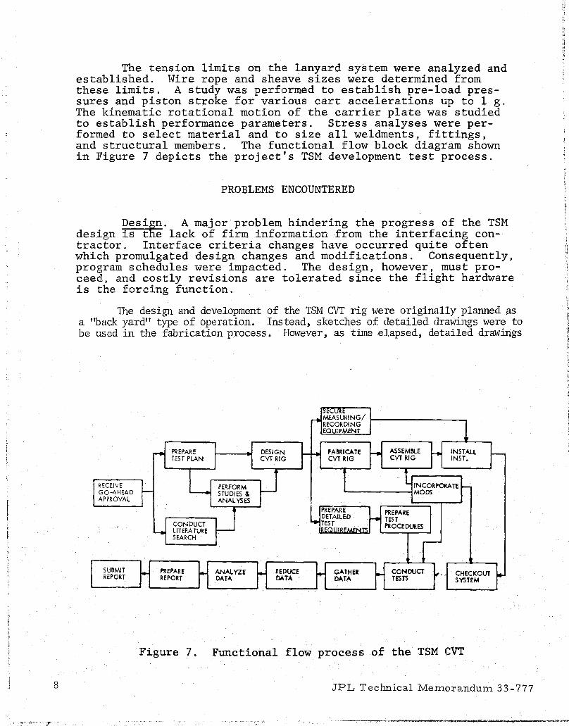
The tension limits on the lanyard system were analyzed and established. l~ire rope and sheave sizes were determined from these limits. A study was performed to establish pre-load pressures and piston stroke for various cart accelerations up to 1 g. The kinematic rotational motion of the carrier plate was studied to establish performance parameters. Stress analyses were performed to select material and to size all weldments, fittings, and structural members. The functional flow block diagram shown in Figure 7 depicts the project's TSM development test process.
PROBLEMS ENCOUNTERED
Design. A majcr problem hindering the progress of the TSM design is t e lack of firm information from the interfacing contractor. Interfa.ce criteria changes have occurred quite often which promulgated design changes and modifications. Consequently, program schedules were impacted. The design, however, must proceed, and costly revisions are tolerated since the flight hardware is the forcing function.
The design and development of the TSM CVT rig were originally planned as a "back yard" type of operation. Instead, sketches of detailed drawings were to be used in the fabrication process. However, as time elapsed, detailed drawings
~ I~~JRING/ RECORDING 1 EQUIPMENT
~ PIl.EPARE DESIGN I-~ FABRICATE r ASSEMBlE f-4oI INSTAll r-TEST PlAN CVT RIG CVT RIG CVT RIG INST.
W J 1 t INCORI'ORA TE l-I ~ECEIVE r PERFORM GO-AHEAD STUDIES & MODS APPROVAL ANALYSES !
W L PREPARE PREPARE DETAILED ~ TEST CONDUCT ~~gL""~' PROCEDURES
4 LITERATURE SEARCH
I SUBMIT } PREPARE t- ANALYZE t- REDUCE r- GATHER I- CONDUCT ~. CHECKOUT Ie-REPORT REPORT DATA DATA OATA TESTS SYSTEM
Figure 7. Functional flow process of the TSM CVT
8 JPL Technical Memorandum 33 -777
~---,",""---'--'~"-"""'-\ij--'-' ------.~

were required, high tolerances and fabrication requirements were levied, and detailed test procedures were developed and employed. Furthermore, excess property was either unavailable or not applicable as initially anticipated. All of these occurrences contributed to test delays and increased cost.
Procurement. Extensive paperwork (red tape) through proper customer-cnannels contributed to delays in receiving needed material and off-the-shelf items. Difficult to obtain (scarce) items, e.g., square T-l steel tubing, contributed to delays in the fabrication process. Up to 17 vendors were contacted for T-l steel tubing but without success. Ultimately, n different type of steel was used instead of T-l. It was determined that A-36, 4130, and 1018 steels are some of the ~ore readily accessible ones. Whenever structural requirements permit, materials that are of lower strength, abundant, and of easy access should be used.
Fabrication. Quality control oversights caused refabrication and/or modifications which impacted the schedule. Concentrated scrutiny must be given to all drawings and fabricated parts to determine if proper dimensioning and tolerancing were usep.
Test, Because funds were not approved for purchasing new or additional instrumentation, available instruments were used. Inconveniences of bor.rowing load cells from other on-going tests, using oscillograph recorders with insufficient number of channels to record all the "quick look" data desired, and using linear accelerometers to acquire angular accelerations had to be tolerated.
TEST PROGRAM
The umbilical carrier plate must be rotated at least 11 degrees before the carrier plate feet will be in a disengageable position. The lanyard system provides the forces which initially' rotate the carrier plate and subsequently stops the rotation while translating the carrier plate. Carrier plate motion is transmittad to the masthead (cart) through a linkage system, which in turn supports the weight of the carrier plate during retraction.
The CVT program was designed to:
a. Verify that the lanyard system, which retracts the carrier after rotating it 11 degrees with the vehicle in the nominal "0" position, will prohibit over-rotation (beyond 15 degrees) when the vehicle is in the launch (up 7 inches) position. Over-rotation may damage or rupture the propellant flex hoses.
b. Verify that the impact of the carrier plate settling to the nominal retract position, when falling from a higher to a lower position, has little effect on mast dynamics.
JPL Technical Memorandum 33-777
1 i
9

" 101
· "' ..
c. Verify that the entire assemblage (carrier plate/lanyard/ links/masthead) behaves in accordance with the time and motion and dynamics equations used to determine the energy requirements of the system.
d. Verify that the load on the umbilical carrier plate by the vacuum jacketed hose is not severe enough to present a bending moment problem.
CONCLUSION
Many lessons were learned during the design, fabrication, and assembly phases of this development project. A major change impacting the prototype TSM design involved the tctal redesign of the links. The telescoping concept was maintained but a fail-safe latching arrangement was developed. Also, constant force hydraulic shock absorbers were used instead of rubber pads.
A theoretical study was made to determine whether or not the carrier plate would flip over the masthead upon impact with the mast shock absorber. Though there would be no problem with the CVT test rig because it moves on horizontal rails, it was determined that there would be an overturning problem with the prototype TSM because the masthead/plate assembly traces an arc. Upon mast/shock absorber impact, the calculated overturning moment showed that the carrier plate would rise over the masthead. Therefore, a number of fixes are being devised to keep the plate rise from occurring. Other revisions reSUlting from this project which were incorporated in the prototype TSM design included cable size, sheave, and sling link changes.
REFERENCES
1. Space Shuttle Level II Program Definition and Requirements, Volume X, Revision A, Space Shuttle Program Flight and Ground System Specification, JSC 07700, Lyndon B. Johnson Space Center, Houston, Texas, January 2, 1974.
2. Space Shuttle Ground Support Equipment General Design Requirements, SW-E-0002, Lyndon B. Johnson Space Center, Houston, Texas, July 1974.
3. General Criteria for Design of New Equipment and Facilities to be Utilized at Kennedy Space Center, Revision 1, GP-863, John F. Kennedy Space Center, ¥SC, Florida, February 2, 1973.
4. Station Set Requiremen.ts Document, Volume 22, Mobile Launch Platform, K-SM-10.l.6, Revision 002, John F. Kennedy Space Center, KSC, Florida, January 31, 1975.
JPL Technical Memorandum 33-7770