Embed Size (px)
Citation preview

N5000 MULTI-LEVEL INVERTER
INSTRUCTION MANUAL
DOC. NO. HHI-N5K-GEN-015

1
SAFETY PRECAUTIONS
N5000 INSTRUCTION MANUAL
Please read the following instructions and directions given in this manual before selecting,
operating, repairing and checking.
Please be advised regarding mechanical safety information, direction and etc before use.
There are two different instructions explained in this manual regarding (danger) and (caution).
DANGER: If not avoided, either death or injuries will occur.
CAUTION: If not avoided, either death or injuries will occur as well as property damage.
Also, Please be advised to read all instructions given in the caution manual as well as danger
manual. It is important to read all the instructions completely.
In the following instruction manual, please note the word “CAUTION”.
* Common Matter
• Due to high voltage consumption, this product can cause electric shocks and fire to the
body and machine. An expert in Installation, driving, control, maintence must operate this
product.
• In order to stop or inspect the machine, you must first cut the high voltage completely.
• Insulation must be ensured between N5000 and the test equipment before applying electric
current for the purpose of test.
A. Installation of System and Wiring
• You must close all the doors whenever moving the inverter panel or installation.
• This machine is not protected from flooding. Please keep this machine away from water
while keeping and moving.
• Avoid from anything inflammable. It may cause fire to the machine.
• Avoid electric wires, welding spark, metal or dust from entering the machine. It may cause
fire.
• Do not operate the damaged inverter further. It may cause further damage.
• Do not connect AC supply to the output terminal.
• Use a power cable and control cable in a proper form.
• Only an expert should do grounding operation for the inverter system based on the
electrical drawing.
• Check the terminal polarities and the terminal numbers.
• Check the connection for loose screws. Loose screws may cause fire to the machine.
• Use proper power cable, VCB and electric contactor. If not, it may cause fire to the machine
DANGER
CAUTION

2
SAFETY PRECAUTIONS
N5000 INSTRUCTION MANUAL
• The equipment must be connected to the ground.
If not connected to the ground, it may cause shock and fire.
• You must first turn off the power in order to do any wiring.
• Installation must be done correctly before doing any wiring.
If done improperly, It may cause electric shock.
• An expert must do all wiring to the machine.
If wiring is done improperly, it may cause fire.
• After any installation, repair or test, you must check for water, dust or piece of wires that
might be in the machine before turning on the power.
B. Operation
• Do not touch the power switch with wet hands. It may cause electric shock.
• When switching on or off electric current, do not push wet hands to the terminal of an
inverter. It may cause electric shock.
• When applying an electric current, do not push anything inside of an inverter. It may cause
electric shock and fire.
• Check the motor if it is turning around to the correct direction. It may cause an accident
and damage to the machine.
• Check for improper sounds or vibration from the motor. It may cause an accident and
damage to the machine.
• In the inverter operator, there is a function to change a variable, invariable and memory that
may induce severe system failure. An expert may only operate this.
• Do not use operator function while the inverter is in use.
C. Repair, Inspection and changing parts
• When inspecting the equipment, turn off the power and wait ten minutes before inspection
to avoid electric shock.
• An expert should do all repairs or changing parts to the machine. (You must remove all
metal parts from your body, which includes watches and other jewelry before working on the
machine.) Only use insulatied tools.
D. Caution of Use
• To avoid electric shock or accidents, use only designated parts and tools for this machine.
CAUTION
DANGER
DANGER
DANGER

1
Table of Contents
N5000 INSTRUCTION MANUAL
TABLE OF CONTENTS
CHAPTER 1. GENERAL DESCRIPTIONS ........................................................................................................... 3
1.1 INSTRUCTION MANUAL ........................................................................................................................................................................ 3
1.2 WARRANTIES ON PRODUCT ................................................................................................................................................................ 3
CHAPTER 2 INSTALLATION AND WIRING ..................................................................................................... 4
2.1 PRECAUTION ......................................................................................................................................................................................... 4
2.2 WIRING ................................................................................................................................................................................................. 5
2.2.1 terminal description .............................................................................................................................................................. 5
2.2.2 Power terminal wiring .......................................................................................................................................................... 7
CHAPTER 3. SPECIFICATION AND OPERATION ........................................................................................... 8
3.1 SPECIFICATION ..................................................................................................................................................................................... 9
3.2 INVERTER FEATURES ..........................................................................................................................................................................11
3.2.1 Composition ...........................................................................................................................................................................11
3.3 OPERATION .........................................................................................................................................................................................13
3.3.1 Inverter circuit ......................................................................................................................................................................13
3.3.2 Power cell circuit ..................................................................................................................................................................17
3.3.3 Inverter Output ....................................................................................................................................................................18
3.3.4 Control Function ...................................................................................................................................................................19
3.3.5 Power Cell Bypass (optional) ..........................................................................................................................................22
3.3.6 PWM method .........................................................................................................................................................................25
3.3.7 Operational Modes ..............................................................................................................................................................33
CHAPTER 4. INVERTER OPERATION ............................................................................................................. 39
4.1 DIRECTION OF OPERATING INVERTER WITH CAUTION .................................................................................................................39
4.2 INVERTER OPERATIONAL MODE ........................................................................................................................................................39
4.2.1 Self-operation by operator ...............................................................................................................................................39
4.2.2 Remote control operation ................................................................................................................................................39
4.2.3 Input/output related operation ......................................................................................................................................39
4.3 N5000 INVERTER TOUCH OPERATOR PANEL COMPUTER (TOPC) ................................................................................................40
4.3.1 TOPC hardware ....................................................................................................................................................................40
4.3.2 TOPC screen organization ................................................................................................................................................42
4.3.3 Operation screen .................................................................................................................................................................43
4.3.4 Waveform screen ...............................................................................................................................................................47
4.3.5 Variables screen .................................................................................................................................................................51
4.3.6 Errors screen .........................................................................................................................................................................54

2
Table of Contents
N5000 INSTRUCTION MANUAL
4.4 VARIABLES FOR INVERTER OPERATION ...........................................................................................................................................40
4.4.1 A code variables .................................................................................................................................................................57
4.4.2 B code variables ...................................................................................................................................................................62
4.4.3 C code variables ...................................................................................................................................................................68
4.4.4 D code variables ...................................................................................................................................................................70
4.4.5 E code variables ...................................................................................................................................................................72
CHAPTER 5 REPAIR AND INSPECTION ......................................................................................................... 83
5.1 REPAIR AND INSPECTION ..................................................................................................................................................................83
5.1.1 Normal inspection ................................................................................................................................................................83
5.1.2 Regular inspection ...............................................................................................................................................................83
5.2 ABNORMALITY INSPECTION ..............................................................................................................................................................84
5.2.1 Warning while inverter running (Alarm) ....................................................................................................................84
5.2.2 Breakdown while inverter running (Fault).................................................................................................................85
5.2.3 Inverter breakdown sequence .......................................................................................................................................87
5.3 INVERTER RESTORATION FROM SYSTEM FAULT ..............................................................................................................................88
5.3.1 For correct inverter restoration ......................................................................................................................................88
5.3.2 Treatment of the inverter cell unit ...............................................................................................................................88
5.3.3 Activation of the inverter after restoration ...............................................................................................................88

3
Chapter 1. General Descriptions
N5000 INSTRUCTION MANUAL
Chapter 1. General Descriptions
1.1 Instruction manual
• The following instruction manual is that of N5000 Inverter made by Hyundai Heavy
Industries Co., LTD. Please read the following direction carefully and completely before
operating an inverter. Atrer reading this manual, keep it to hand for future reference.
• The N5000 inverter is consisted only main panel.
Please make the system with input and output VCB likes Fig1.
Input and output VCB can be controlled by X12 and X13 terminals. (6~7page)
< Fig1. N5000 Instruction Block Diagram >
1.2 Warranties on Product
• Warranties on this product are based on the time of contract on the supply. However within the
warranty period, the warranty will be void if the fault is due to;
(1) Incorrect use as directed in this manual or attempted repair by unauthorized personnel.
(2) In the case that the reason of fault is out of the inverter.
(3) Using the unit beyond the limits of the specification.
(4) Natural disaster (earthquake, thunderstorm etc.)
• The warranty is only for inverter, any damage caused to other equipment by malfunction of the
inverter is not covered by the warranty.
Any examination or repair after the warranty period (one-year standard) is not covered. And
within the warranty period, any repairs and examinations which result in information showing
the faults were caused by any of the items mentioned above, the repair and examination cost
are not covered. If you have any questions regarding the warranty, please contact either your
supplier or the local HYUNDAI Distributor. Please refer to the back cover for a list of the local
HYUNDAI Distributors.

4
Chapter 2. Installation and Wiring
N5000 INSTRUCTION MANUAL
Chapter 2 Installation and Wiring
2.1 Precaution
Please observe the environmental guidelines below.
No. Item Description
1 Ambient temperature
Temperature range shall be between 0 and +40.
The daily mean temperature shall be between 5 and 35
2 Relative humidity
Shall be under 50% at the maximum temperature of 40.
Even at low temperature, it shall not exceed 85%.
There shall be no condensation due to temperature changes.
3 Altitude Shall be below 1000m above sea level.
4 Atmospheric pressure Shall be within the range of 860 - 1060hPa.
5 Vibration
The vibration frequency at an installation site shall be below
10Hz or above 20Hz.
If it is below 10Hz, the acceleration of vibration shall be below
0.3G.
If the frequency is between 20Hz and 50Hz, the acceleration
shall be below 0.3G.
If the frequency is between is 50Hz and 100Hz, the full
amplitude shall be below 0.1mm.
6 Air quality of the room The air conditions in the room where the equipment is
installed should be kept in the normal air dust level, and
especially be free of iron and organic particles suchas silicon.
7 Corrosive factors Density or quantity
Corrosive
gas
Hydrogen sulfide (H2S) 0.001 PPM or less
Sulfur dioxide (SO2) 0.05 PPM or less
Chloride gas (Cl2) 0.1 PPM or less
Ammonia gas (NH3) 0.1 PPM or less
Nitrogen dioxide (NO2) 0.02 PPM or less
Nitrogen oxide (NOx) 0.02 PPM or less
Ozone (O3) 0.002 PPM or less
Hydrochloric acid mist (HCl1) 0.1 mg/m3 or less

5
Chapter 2. Installation and Wiring
N5000 INSTRUCTION MANUAL
Notice
• When cleaning the equipment room, please use a vacuum cleaner lest dust will be stirred up.
• Do not apply silicon wax to the floor in the equipment room. It will have a negative effect on the
electric contact.
• After an external cable (grounding wire, main circuit cable and control wire) is led into the panel
completely seal the cable lead-in hole with putty.
If the cable lead-in hole is left unfilled, fresh air will enter the equipment, preventing the above
installation environment from being secured, which may cause serious damage to the equipment.
2.2 Wiring
Power must be turned off when working on wiring to avoid electric shock.
Wiring work shall be carried out by expert electrician.
Implement wiring after checking that the power supply is off. It might incur electric shock
and fire.
Check the polarity and the numbers on the terminal and connect them correctly.
2.2.1 terminal description
(1) Power terminals
Terminal block Terminal name Description
X1 R, S, T Main power input
X2 U, V, W Inverter output
X01 R1, S1, T1 3 phases AC 440V control power input
X02 P01, N01 Control power input (DC110V)
(2) Control signal terminals
Terminal block Terminal name Description
X11 5∼6 / 7∼8 Analog input(4∼20mA)
X12 20∼27, 29∼36
28, 37 : Common Digital output (Dry contact)
X13
1~8
11∼12
13∼14
15∼16
Analog input and output (4∼20mA)
WARNING

6
Chapter 2. Installation and Wiring
N5000 INSTRUCTION MANUAL
* Terminal block diagram example

7
Chapter 2. Installation and Wiring
N5000 INSTRUCTION MANUAL
2.2.2 Power terminal wiring
(1) Warning on Wiring
- Make sure that the power supply is off before connecting the main cable to the inverter input.
-Check if MCCB (Molded Case Circuit Breaker) for control power is off, when connecting the
control power to the inverter.
① Main power input terminals (R, S, T)
• N5000 uses 3-phase power source. Do not use single-phase power source.
• Connect input power cable to the inverter through the bottom of the transformer panel.
• When turning on or off the inverter using VCB(Vacuum Circuit Breaker), please keep the
frequency of on/off operations in accordance with the VCB specification.
② Inverter output terminals (U, V, W)
• Lines from inverter output terminals should be out from the bottom of the transformer panel
of the inverter.
• Do not install condenser for power factor improvement or surge absorber to the output
terminals. They may cause damage to the inverter.
• Ask manufacturer for correct use when you use a filter to restrain Surge voltage.
③ Ground (G)
• Make sure that you securely ground the inverter and motor to prevent electric shock.

8
Chapter 3. Specification and Operation
N5000 INSTRUCTION MANUAL
Chapter 3. Specification and Operation
* The following material can be changed as revising structural design without notice. Please
ask to HHI directly to confirm the exact dimension.
Voltage
(V)
N5000
Type
Capacity
(kVA)
Output
Current(A)
Dimension (mm)
Width Height Depth
3kV Class:
3300V,
3000V
155L 200 35 2000 2850 1200
245L 300 53 2000 2850 1200
325L 400 70 2400 2850 1200
410L 500 88 2400 2850 1200
490L 600 105 3300 2850 1200
620L 750 132 3300 2850 1200
835L 1000 175 3600 2850 1200
1040L 1250 219 3600 2850 1200
1270L 1500 263 3800 2850 1400
1500L 1750 307 3800 2850 1400
1710L 2000 350 3900 2850 1400
1940L 2250 394 3900 2850 1400
6kV Class:
6600V,
6000V
330H 400 35 3200 2850 1200
495H 600 53 3200 2850 1200
675H 800 70 3900 2850 1200
835H 1000 88 3900 2850 1200
1000H 1200 105 4900 2850 1200
1270H 1500 132 4900 2850 1200
1700H 2000 175 5100 2850 1200
2130H 2500 219 5100 2850 1200
2590H 3000 263 5200 2850 1400
3020H 3500 307 5700 2850 1400
3450H 4000 350 5900 2850 1400
3930H 4500 394 6000 2850 1400

9
Chapter 3. Specification and Operation
N5000 INSTRUCTION MANUAL
3.1 Specification
Item Specification
Inverter Type Voltage type (Series connection with H-bridge circuit, multilevel
output)
Input Voltage 3 kV class: 1) 3300V ± 10%
6 kV class: 1) 6600V ± 10%
Input Transformer Dry type multiphase coil transformer with built-in panel
Input Frequency 50Hz/60Hz ± 5%
Input Rectification 3kV class: 18pulse diode rectification, 6k class: 30pulse diode
rectification
Input Current Harmonics THD < 5%
Input Power-Factor 0.95
Output voltage 3phase 0~3000V, 0~3300V,0~4190V, 0~6000V, 0~6600V
Output voltage level 3kV: 13 level (space voltage), 6kV: 21 level (space voltage)
Output Frequency 0 ~ 120Hz
Rated operation range 100% load: continuous operation, 120% overload: 1min
Main power element &
modulation method IGBT, PWM
Efficiency 97% (rated operation)
Cooling Compulsive air cooling
Standard IEC
Ambient temperature 0∼40
Humidity < 85% non-condensation

10
Chapter 3. Specification and Operation
N5000 INSTRUCTION MANUAL
Item Specification
Signal
Input, output
Input Digital Input (DI): 16 CH.
Analogue Input (AI): 4 CH.
Output
Digital Output (DO): 8 CH.
Analogue Output (AO): 4 CH.
(4~20mA)
Protection
Output overpower, DC over-voltage, DC under-voltage, CAN
communication failure, transformer over-temperature,
power cell inverter over temperature, Power cell fuse
damage, CPU eroor(installed redundant control board)
Control
V/F Operation
Torque mode Linear torque, 1.7th / 2nd power reduced
torque
Acceleration/dec
eleration mode
Deceleration: Linear
Acceleration: Linear, U/ RU/ S shape
Torque boost, Frequency jump, preventing stall
Sensorless vector control
options Vector control using Encorder, Bypass the damaged power
cell, Dualized control, Dualized control power
Cubicle protection class IP 41 (Cooling fan : IP20)

11
Chapter 3. Specification and Operation
N5000 INSTRUCTION MANUAL
3.2 Inverter features
N5000 is a Cascaded H-bridge type voltage inverter, which generates high 3-phase voltage by
cascading single-phase low-voltage inverters of insulated DC part. Multi-winding transformer is
used for numbers of independent insulated DC parts. And input harmonics content is reduced by
installing 30 pulse (3kV class: 18 pulse) diode rectification part with phase differences of windings.
The improved structure enabled N5000 to generate high quality output voltage without a filter
that reduces harmonics and to utilize previously established motors and cables.
3.2.1 Composition
N5000 is composed of transformer panel, inverter (power cell unit) panel and control panel as
shown in Figure 3-1.
Figure 3-1 composition of N5000 inverter panel
A dry type multi-winding transformer is equipped in transformer panel. The 2nd winding of Multi-
winding transformer is constituted of 3 phase-5 winding groups with 12 degree phase differences
so that each winding is connected to the input terminal of power cell unit inside inverter panel for
6kV class. And the 2nd winding of multi-winding transformer for 3 kV class is constituted of 3
phase-3 winding groups with 20 degree phase differences.
Cooling fans are installed on top of all transformer panels for both 3kV and 6kV classes. The air
groove is separated from inverter/control panel and used for self cooling.

12
Chapter 3. Specification and Operation
N5000 INSTRUCTION MANUAL
Each phase of U, V, and W has its own serially connected 5 power cells so that the total number
of power cells is 15 for 6kV class. For 3kV class, each phase of U, V and W has serially connected 3
power cells so that the total number of power cells is 9.
Every cell has the same electrical and structural shape and acts as a single phase inverter by
using IGBT power semiconductor. Each cell has its own control unit. Power cell control unit and
main control unit are connected by optical cable. Air, which is inhaled from front panel filter, goes
through heat sink of power cell unit, air groove and then exhaled out of cooling fan on top of the
inverter.
Figure 3-2. inside of inverter panel.
Main control PCB, control power, signal insulator, relay, MCCB, power transformer and terminal
blocks for control power and signal line input/output are installed on both front and side part of
control panel.

13
Chapter 3. Specification and Operation
N5000 INSTRUCTION MANUAL
Figure 3-3-A Front view Figure 3-3-B Side view
3.3 Operation
N5000 inverter is a Cascaded H-bridge type voltage inverter, which generates 3-phase voltage
using serially connected single inverters (power cell unit).
3.3.1 Inverter circuit
Figure 3-4 shows the 6kV-class inverter power circuit. 3 phase power supply is supplied to each
of the power cell units through input transformer. Inverter of a power cell unit generates variable
voltage and variable frequency of single phase. And then the 5 power cell units are serially
connected to compose the output phase power. Finally, voltage between lines is generated through
Y connection between phases. Electric circuit of this type is named as “cascaded H-bridge
multilevel.”

14
Chapter 3. Specification and Operation
N5000 INSTRUCTION MANUAL
Figure 3-4-A. 6kV-class N5000 inverter electric circuit

15
Chapter 3. Specification and Operation
N5000 INSTRUCTION MANUAL
Figure 3-4-B. 3kV-class N5000 inverter electric circuit
DC power supplies for the power cells of 15 H-bridge type should be separated to generate
6600V/6000V voltage output in 6kV-class N5000 series inverter. So the number of the 2nd
windings is made equal as the number of the power cells by utilizing multi-winding transformer. 6
windings (3 windings in 3kV-class) of each group have 12 degree phase differences (20 degree in
3kV-class) with each other by grouping the 2nd windings to 3 phases to minimize the harmonics
which are generated by using diode rectification circuit in each of the power cells. The transformer
of this type makes rectification part of 30-pulses for 6kV-class and 18-pulses for 3kV-class so that
the THD (Total Harmonic Distortion) ratio of the 1st side of transformer can be reduced below 5%
which is complied with the IEEE std. 519-1992 (Harmonic Voltage and Current Limits).
16
Chapter 3. Specification and Operation
N5000 INSTRUCTION MANUAL
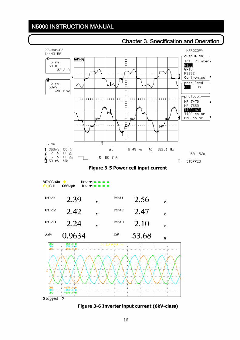
Figure 3-5 Power cell input current
Figure 3-6 Inverter input current (6kV-class)

17
Chapter 3. Specification and Operation
N5000 INSTRUCTION MANUAL
3.3.2 Power cell circuit
All power cells within N5000 inverter are of the same structure and composed of the same
electric circuits. They are operated as a inverter of 3-phase 760V intput type. Each power cell
consists of parts of the power supply and the control. Power supply part is consisted of parts of
the diode recification and the single-phase inverterusing IGBT. Capacitors are installed for the
protection of instant electrical failure and as the smooting-voltage circuit in DC part. Compulsive
air cooilng method is used to cool down the power elements using aluminum heat sink.
The Control part of power cell consists of the devices for power control and the DSP control
board. The devices for power control are supplied from main DC supply and make DC supplies for
controlling. DSP control board implements voltage PWM (Pulse width modulation) which generates
a voltage value determined by main control part, protective functions for DC over-voltage,
disconnection of input fuse for power cell and heat-sink and CAN (Controller Area Network)
communication control between main control part and elements using optical cable.
Figure 3-7 Power cell electric circuit
Figure 3-8 Power cell structure

18
Chapter 3. Specification and Operation
N5000 INSTRUCTION MANUAL
760V from transformer is raised up to 1029V in rectification part of power cell. And power cell is
modulated to generate 762V/693V for the inverter final 6600V/6000V output because 5 power cell
outputs are serially connected for each phase in 6kV-class inverter. (Each power cell output of
3kV-class has 635V/577V because 3 power cells are serially connected for 1 phase in 3kV-class.)
Power circuit connections for power cell unit use busplates and busbars to minimize parasitic
inductance effect. Inverter circuit of the power cell inverts DC voltage to single phase AC voltage
and implements PWM for output voltage using on/off controllable IGBT.
3.3.3 Inverter Output
Maximum size of output voltage of each power cell unit is 762V. In the 6kV-class N5000 inverter,
six 762V units are serially connected to achieve 3810V and the 3810V units generate 6600 line
voltage using Y-connection as shown in figure 3-9.
※ Inside value of ( ) is the voltage when considering maximum N5000 inverter output as 6000V.
Single- connectedSingle- phase
Inverter
Interline VoltageVab=6,600V
Phase VoltageVa=3,810V
IGBT Output Voltage
762V
U
VW
V5
V4
V3
V2
V1
U5
U4
U3
U2
U1
W5
W4
W3
W2
W1
762V
762V
762V
762V
Figure 3-9 Voltage outputs of multilevel H-bridge inverter power cell output
Figure 3-10 output voltage curve of a power cell

19
Chapter 3. Specification and Operation
N5000 INSTRUCTION MANUAL
Also, 21 levels (13 levels for 3kV-class) quasi-sinewave outpt based on the line voltage can be
achieved when the serially connected 5 power cell unit outputs that are allocated to each phase
have phase differences. This output characteristic of N5000 makes it to operate pre-installed
motors without additional filter.
Figure 3-11 voltage output curve of 6kV-class N5000 inverter
3.3.4 Control Function
Control part of N5000 inverter is composed of main control part, which is in charge of system
operations, controls, failure detections and protections, and the power cell controller that is
installed in the power cell. Main control part is located at the left side of control panel and
composed of CPU board, digital/analog I/O boards and optical converter board. Operator using
touch-keypad is installed at the front panel and has SMPS (Switched-mode power supply) for DC5V,
± 15V, 24V output to operate main control part and operator etc.

20
Chapter 3. Specification and Operation
N5000 INSTRUCTION MANUAL
Figure 3-12 Organization of N500 Inverter master control
*CPU board
CPU board controls the system by exchanging signals with the I/O board. Also, it calculates the
inverter output value for controlling loaded motor speed and transfers the value to each power cell
controller through CAN communication. Power cell controller implements control for PWM in
accordance with the received control values from main control part and generate gate pulses for
IGBT to make adequate voltage and phase values for an induction motor. Operational information
of each power cell inverter is delivered to the main control part through CAN communication, and
the main control part makes inverter system perform a corresponding work. Figure 3-13 shows the
inside composition of CPU board. Main process elements are highspeed digital signal processor and
core part that is composed of integrated logic gate elements, EEPROM, SRAM and NVRAM.
Communication part is composed of CAN communication controlling device, RS235, serial
communication control device of RS485 and local bus for system expansion.
*I/O board
I/O board is consisted of digital I/O and analog I/O board. And a circuit for 16 digital input and 8
insulated digital output (contact) channels is installed in DIO board. A 4 channel analog input
circuit, which converts 4~20mA input signal to voltage and convert the voltage to digital signal
using differential amp, and an analog output circuit, which generates output voltage from 0 to 10V
using DA converter, are installed in AIO board.

21
Chapter 3. Specification and Operation
N5000 INSTRUCTION MANUAL
*Optical conversion board
Optical/Electrical signal conversion circuit that can reduce the noise effects between the main
control part and the power cell control part and optical cable connector are installed in optical
conversion board. Optical conversion circuit guarantees 5Mbps communication speed for CAN
communication.
Figure 3-13 Organization of CPU board circuit
* Power cell control board
Power cell control board performs PWM for IGBT and generates phase differences in accordance
with the control command from main control part. It also contains protective ground detection
circuit. Communication control circuit for CAN communication, optical conversion circuit, serial
communication control circuit for program download and PC connection port for individual power
cell test are installed in the board.

22
Chapter 3. Specification and Operation
N5000 INSTRUCTION MANUAL
Cell Controller Function
* Cell Control
(PWM, Phase-shift)
* Master/Cell Communication
* Cell Protection
* Cell Monitoring
* Cell Diagnostic
CELL
CONTROLLER(TMS320LF2406A)
GATING
(Power Cell PWM)
SENSING
(DC Voltage, Fault)
CELL
CONTROLLER(TMS320LF2406A)
CELL
CONTROLLER(TMS320LF2406A)
OPERATOR
RS232
RS485
Master Controller Function
* System Control(Speed,Current)
* Master/Cell Communication
* System Protection
* System Monitoring
* System Diagnostic
OPTICAL LINK
Using CAN(1M bps)
Operator Function
* Operation Command
* Monitoring
* Maintenance
MASTER CONTROLLER(TMS320C31)
A1 B1
A2 A3 A4 A5 A6 B2 B3 B4 B5 B6 C2 C3 C4 C5 C6
C1
CAN CAN CAN
Speed & Current Control
Power Cell State
Va* Vb* Vc*
SENSING
(Input Voltage, Output
Voltage/Current, Speed)
Sync. Tx EnableSync. Tx EnableSync. Tx Enable
Figure 3-14.1 Organization of Inverter control part
Figure 3-14.2 power cell control board
3.3.5 Power Cell Bypass (optional)
It is common to halt all the inverter system when the power cell failure occurs. But in “Power Cell
Bypass” method, inverter eliminates only the layer in which power cell failure occurred and keeps
running for high inverter efficiency.
In N5000 series, additional bypassing switches are installed to run the inverter with lowered
voltage for important loads that should not be stopped. So that operator can fix the inverter
without stopping. Additional switches are composed of bidirectional SCRs because the 3-phase
current of the load is bidirectional.
Optic connector
Program download connector

23
Chapter 3. Specification and Operation
N5000 INSTRUCTION MANUAL
Bypass Circuit
A1 POWER CELL
A2 POWER CELL
B1 POWER CELL
B2 POWER CELL
C1 POWER CELL
A
B
POWER CELL
R
T
S BYPASS
Cell ControllerMaster
ControllerSerial Communication Using Optical Cable
Figure 3-15. Power Cell Bypass electricity circuit consisting 2 Layer
< Vector diagram and simulation in Bypass operation>
Followings are describing the bypass operations in normal and power cell failure cases using
vector diagram and simulation.
Normal operation
In figure 3-16, the line voltage becomes 380V, 5-output voltage levels by serially connecting 2
power cells for each phase. At this time, voltages of 3 phases should be balanced. Fight side of
figure 3-16, output line voltages (Vab, Vbc, Vca) and the output current of RL load are shown.
B2110V
380 Volts Max (Line-To-Line)
A
BCVbc
VcaVab
1200
A1110V
A2110V
B1110V
C1110V
C2110V
1200
1200
Figure 3-16. Power Cell No-Fail

24
Chapter 3. Specification and Operation
N5000 INSTRUCTION MANUAL
Cell Bypass Operation when Power Cell Fails
Figure 3-17 shows that the cell bypass function can generate 50% out of rated voltage, 190V, by
connecting power cells in layer 2 using SCR in the case of power cell failure of layer 2.
A
BCVbc
Vca Vab
1200
A1110V
B1110V
C1110V
1200
1200
Maximum Voltage = 190 (50.0%)
Figure 3-17. A2, B2, C2 Power Cell Fail
25
Chapter 3. Specification and Operation
N5000 INSTRUCTION MANUAL
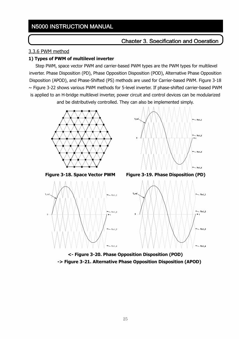
3.3.6 PWM method
1) Types of PWM of multilevel inverter
Step PWM, space vector PWM and carrier-based PWM types are the PWM types for multilevel
inverter. Phase Disposition (PD), Phase Opposition Disposition (POD), Alternative Phase Opposition
Disposition (APOD), and Phase-Shifted (PS) methods are used for Carrier-based PWM. Figure 3-18
~ Figure 3-22 shows various PWM methods for 5-level inverter. If phase-shifted carrier-based PWM
is applied to an H-bridge multilevel inverter, power circuit and control devices can be modularized
and be distributively controlled. They can also be implemented simply.
V_ref Vtri_1
Vtri_2
Vtri_3
Vtri_4
0 t
Figure 3-18. Space Vector PWM Figure 3-19. Phase Disposition (PD)
V_ref Vtri_1
Vtri_2
Vtri_3
Vtri_4
0 t
V_ref Vtri_1
Vtri_2
Vtri_3
Vtri_4
0 t
<- Figure 3-20. Phase Opposition Disposition (POD)
-> Figure 3-21. Alternative Phase Opposition Disposition (APOD)

26
Chapter 3. Specification and Operation
N5000 INSTRUCTION MANUAL
V_refVtri_1 Vtri_2 Vtri_3 Vtri_4
0 t
Figure 3-22. Phase-Shifted (PS)
2) Operational principle of individual power cell
H-bridge circuit of power cell has 4 modes of voltage output as shown in figure 3-23.
Mode 1: switch GA1 is on , switch below GA2 is on output voltage is V.
Mode 2: switch below GA1 is on, switch below GA2 is on output voltage is 0.
Mode 3: switch GA1 is on, switch GA2 is on output voltage is 0.
Mode 4: switch below GA1 is on, switch GA2 is on output voltage is –V.
GA1 GA2
V V
0
GA1 GA2
V
(a) Mode 1 (b) Mode 2
0
GA1 GA2
V
-V
GA1 GA2
V
(c) Mode 3 (d) Mode 4
Figure 3-23. Equivalent circuits of individual power cells

27
Chapter 3. Specification and Operation
N5000 INSTRUCTION MANUAL
3) Operational pricipal of serially connected two power cells
' ' ' '( 1 4 2 3) 1 ( 1 4 2 3 ) 2AV H H H H V H H H H V
Mode 1: V1 = V2 = V output voltage = 2V. If load current is in positive direction, capacitors C1
and C2 discharge electricity to provide current. If load current is in negative direction, load current
charges C1 and C2.
(a) Mode 1
Mode 2: Output voltage is = V. When load current is in positive direction, Va=V and Vn=0 charge
capacitor C1. When Va=0 and Vb=V, capacitor C2 discharges electricity. If load current is in
negative direction, switching conditions of H1= H4=1 and H1'=H4'=1 charge capacitors C1 and C2.
(b) Mode 2
H3
H2
V1
C1
H3
H2
V2
C1
H1
H4
H1
H4
n
a
iaH3
H2
V1
C1
H3
H2
V2
C1
H1
H4
H1
H4
n
a
ia
H3
H2
V1
C1
H3
H2
V1
C1
H1
H4
H1
H4
n
a
ia

28
Chapter 3. Specification and Operation
N5000 INSTRUCTION MANUAL
Mode 3: Output voltage is 0. When load current is in positive direction, Va=V and Vn=-V make C1
discharge and C2 to be charged. If Va=-V and Vn=V, C1 is charged and C2 discharges. When load
current is in negative direction, Va=V and Vn=-V make C1 to be charged and C2 discharge. If Va=-
V and Vn=V, C1 discharges and C2 is charged.
(c) Mode 3
Mode 4: Output voltage is -V. When load current is in positive direction, IGBTs H2, H3, H2' and
H4' are turned on, and C1 charges. If H2, H4, H2', and H3' are turned on, C2 is charged. When
load current is in negative direction, H2, H3, H2', and H4' are turned on and C1 discharges. If H2,
H4, H2' and H3' are turned on, C2 discharges.
(c) Mode 4
H3
H2
V1
C1
H3
H2
V2
C1
H1
H4
H1
H4
n
a
iaH3
H2
V1
C1
H3
H2
V2
C1
H1
H4
H1
H4
n
a
ia
H3
H2
V1
C1
H3
H2
V2
C1
H1
H4
H1
H4
n
a
iaH3
H2
V1
C1
H3
H2
V2
C1
H1
H4
H1
H4
n
a
ia

29
Chapter 3. Specification and Operation
N5000 INSTRUCTION MANUAL
Mode 5: Output voltage is -2V. H2, H3, H2', and H3' are turned on, output voltage becomes -2V.
When load current is in positive direction, load current charges C1 and C2. When load current is in
negative direction, load current makes C1 and C2 discharge.
(c) Mode 5
Figure 3-24. Equivalent Circuit of serially connected two Power Cells.
H3
H2
V1
C1
H3
H2
V2
C1
H1
H4
H1
H4
n
a
ia
30
Chapter 3. Specification and Operation
N5000 INSTRUCTION MANUAL
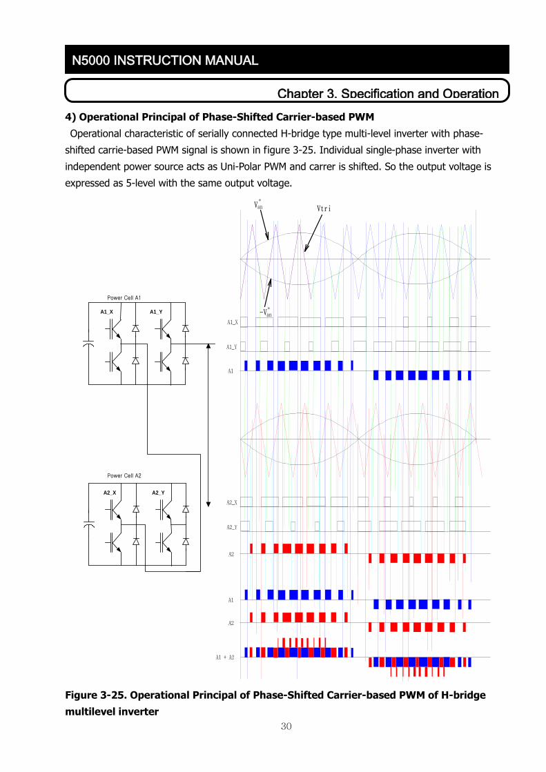
4) Operational Principal of Phase-Shifted Carrier-based PWM
Operational characteristic of serially connected H-bridge type multi-level inverter with phase-
shifted carrie-based PWM signal is shown in figure 3-25. Individual single-phase inverter with
independent power source acts as Uni-Polar PWM and carrer is shifted. So the output voltage is
expressed as 5-level with the same output voltage.
A1_X
A1_Y
A1
A2_X
A2_Y
A2
A1
A1 + A2
VtriVan*
-Van*
A1_X A1_Y
A2_X A2_Y
Power Cell A1
Power Cell A2
A2
Figure 3-25. Operational Principal of Phase-Shifted Carrier-based PWM of H-bridge
multilevel inverter

31
Chapter 3. Specification and Operation
N5000 INSTRUCTION MANUAL
5) Synchronization of Power Cell PWM and phase control block diagram
Figure3-26 is a Power Cell’s phase controlling block diagram using optical cable and serial
communication for 6kV-class N5000 inverter. Voltage commands Va*, Vb*, and Vc* are delievered
to power cell controller through main controller using CAN communication, and the Power Cell
controller initializes inner timer for PWM signal generation in accordance with the interrupt signal
from CAN communication. 1 layer of each phase has no phase-delay. 1/5 of a sampling period for
2 layer, 2/5 for 3 layer, 3/5 for 4 layer and 4/5 for 5 layer phase delays of PWM are occur.
Power Cell C5
Power Cell C4
Power Cell C3
Power Cell C2
Power Cell C1
Power Cell B5
Power Cell B4
Power Cell B3
Power Cell B2
Power Cell B1
Power Cell A5
Power Cell A4
Power Cell A3
Power Cell A2
Power Cell A1 Non Phase-shift
& PWM Generation
1/5 Ts Phase-shift & PWM Generation
2/5 Ts Phase-shift & PWM Generation
3/5 Ts Phase-shift & PWM Generation
4/5 Ts Phase-shift & PWM Generation
Speed & Current Controller
Va*
Vb*
Vc*
Master Controller Cell ControllerSerial Communication* Speed & Current Sensing* Speed & Current Control* Voltage Command Generation* Sync. Tx Enable* Cell Communication* System Protection & Monitoring* TMS320C31 CPU
* DC Link Voltage Sensing* Phase-shift* PWM Generation* Bypass Switch Control* Master Communication* Cell Protection & Monitoring* TMS320LF2406A CPU (including CAN)
CAN
* CAN* 1M bps* Optical Cable
Power Cell* 3 φ Diode Retifier* 1φ PWM Inverter* 5 Layer* 15 EA
Non Phase-shift & PWM Generation
1/5 Ts Phase-shift & PWM Generation
2/5 Ts Phase-shift & PWM Generation
3/5 Ts Phase-shift & PWM Generation
4/5 Ts Phase-shift & PWM Generation
Non Phase-shift & PWM Generation
1/5 Ts Phase-shift & PWM Generation
2/5 Ts Phase-shift & PWM Generation
3/5 Ts Phase-shift & PWM Generation
4/5 Ts Phase-shift & PWM Generation
CAN
CAN
Figure 3-26. Synchronization of Power Cell PWM and phase control block diagram
6) Realizational method for the synchronization and phase transition of Power Cell
PWM.
32
Chapter 3. Specification and Operation
N5000 INSTRUCTION MANUAL
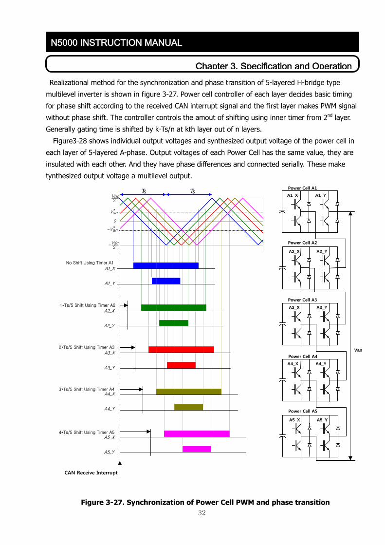
Realizational method for the synchronization and phase transition of 5-layered H-bridge type
multilevel inverter is shown in figure 3-27. Power cell controller of each layer decides basic timing
for phase shift according to the received CAN interrupt signal and the first layer makes PWM signal
without phase shift. The controller controls the amout of shifting using inner timer from 2nd layer.
Generally gating time is shifted by kTs/n at kth layer out of n layers.
Figure3-28 shows individual output voltages and synthesized output voltage of the power cell in
each layer of 5-layered A-phase. Output voltages of each Power Cell has the same value, they are
insulated with each other. And they have phase differences and connected serially. These make
tynthesized output voltage a multilevel output.
Van
A4_X A4_Y
A5_X A5_Y
Power Cell A4
Power Cell A5
A1_X A1_Y
A2_X A2_Y
A3_X A3_Y
Power Cell A1
Power Cell A2
Power Cell A3
Vdc2
-Vdc2
0
Van*
Van*
-
Ts Ts
2*Ts/5 Shift Using Timer A3
4*Ts/5 Shift Using Timer A5
CAN Receive Interrupt
No Shift Using Timer A1
1*Ts/5 Shift Using Timer A2
A1_X
A1_Y
A2_X
A2_Y
A3_X
A3_Y
A4_X
A4_Y
A5_X
A5_Y
3*Ts/5 Shift Using Timer A4
Figure 3-27. Synchronization of Power Cell PWM and phase transition

33
Chapter 3. Specification and Operation
N5000 INSTRUCTION MANUAL
Figure 3-28. Multilevel output voltage
3.3.7 Operational Modes
There are three kinds of operational mode such as V/F mode, vector control mode, and speed
sensorless control mode. It is set in the group A of the inverter operator menu.
1) V/F mode
V/F mode is the most commonly used AC-motor controlling method. Inverter controls the ratio
between the inverter output voltage and the output frequency so that it can control the size of
magnetic flux of AC-motor. When load is increased, the current of the motor is automatically
increasing accordingly. V/F mode can be realized simply and efficiently without any sensors. So,
V/F mode is set as basic in N5000 series.

34
Chapter 3. Specification and Operation
N5000 INSTRUCTION MANUAL
인
버
터
Voltage
charictoristic
*
cmdf *f
*V
Ramp generator
I M
Figure 3-29. V/F operational block diagram
2) Vector control mode
Vector control mode separately controls torque and magnetic flux. When magnetic flux of
electromotor rotates on the space vector, it detects instant location of stator or rotation of
magnetic flux vector and decide standard vector. And then, it detects stator current and reflects it
to magnetic standard flux vector. Through this way, it separates exciting current and torque
current. Exciting current is the current component that has the same directional component with
the standard flux vector. Torque current is the component that has 90° phase difference with the
magnetic flux. Detected exciting current and torque current are controlled by the command of
current controller. The commanded values for torque current and exciting current are decided by
the rated value of motor and operational condition. This mode is used for the purpose of high
efficient variable control. It is possible to set this mode up through operator.
Inverter
Speedsensor
*N
*
actN
CalcurationCurrent
controller
*
qsi
*
dsi
*si *
sV
I M
Speed
controller
Figure 3-30. Vector control block diagram
I
N
V E
R T
E R

35
Chapter 3. Specification and Operation
N5000 INSTRUCTION MANUAL
3) Speed-sensorless vector control mode
Adaptive Observer is used for measuring the speed of motor.
.
1/sB
A
C
SpeedAdaptation
G
+
-
X+
+sdqr
sdqsi
sdqsV
rr
sdqs
sdqs ii ˆ
-s
dqssdqs ii ˆ
sdqsi
idqse
X : Estimation State Vector A : Estimation State MatrixB : Estimation Input Matrix C : Output Matrix G : Observer Gain Matrix 1/s : Integraleidqs : Current Estimation Error
Induction Motor
Figure 3-31. Speed estimator block diagram in speed sensorless vector control mode.
State equation of motor:
Estimated motor speed:
sssdt
diiGBVxAx ˆˆˆˆ
s
qs
s
qsiqs
s
ds
s
dsids
s
driqs
s
qridsi
s
driqs
s
qridspr
iieiie
dteeKeeK
ˆˆ
ˆˆˆˆˆ

36
Chapter 3. Specification and Operation
N5000 INSTRUCTION MANUAL
4) V/F control block diagram
Delta
Freq
uenc
y
Calcu
lation
Freq
uenc
y_Co
mmen
d
Analo
g_In
put(4
~20m
A)
Freq
uenc
y_In
put
Analo
g Sca
lerCo
ntrol
Mod
e
Selet
e
Acce
lerate
_Tim
e
Dece
lerate
_Tim
e
Acce
lerate
_Mod
e
Dece
lerate
_Mod
e
Max
imum
_Freq
uenc
y
Mini
mum
_Freq
uenc
y
Base
_Freq
uenc
y
Calcu
lated
_Freq
uenc
y
Jump
ing_P
oint_
1
Jump
ing_P
oint_
2
Jump
ing_P
oint_
3
Point
_1_w
idth
Point
_2_w
idth
Point
_3_w
idth
CT_A
CT_B
CT_C
CT_S
caler
LIM
ITER
CT_L
imite
d_Va
lue
DC-L
INK
1 ~ 18
LIM
ITER
DC-L
INK_
Limi
ted_V
alue
Jump
ing F
reque
ncy
Calcu
latio
n
Jump
ing_P
oint_X
Point
_X_W
idth
* 2
Boos
t_Mod
e
Boos
t_Fre
quen
cy
Boos
t_Volt
age
Calcu
lated
_Freq
uenc
y
Boos
t_Fre
quen
cy
Boos
t_Volt
age
Boos
ting F
uncti
on
Calcu
lation
Va, V
b, V
cRe
fere
nce
Calcu
lation
[참고
] 1
.
의
셋팅
은 C
ONTR
OL 판
넬전
면부
에있
는오
퍼레
이터
에서
입력
/수정
가능
함.

37
Chapter 3. Specification and Operation
N5000 INSTRUCTION MANUAL
5) Vector control block diagram
a-b-cto
ds-qs
Eqn. (2)
dscomp-qs
comp
toa-b-c
Eqn. (7)
de-qe
tods-qs
Eqn. (4)
Kp+Ki/s
Kp+Ki/s
Kp+Ki/s
Ias
Ics
Ibs
Vas*
Vbs*
Vcs*
ωr*
Iqse*
Idse*
Iqse
Idse
θ
Vqse*
Vdse*
θ
+-
SPEED
CONTROLLER
Q-AXIS CURRENT
CONTROLLER
D-AXIS CURRENT
CONTROLLER
I M
ωr
∫
Iqse*
Idse*
1
Tr
ωsl*
ωe
ωr
Encoder
+-
+-
+-
++
ds-qs
tode-qe
Eqn. (3)
A6
A5
A4
A3
A2
A1
B6
B5
B4
B3
B2
B1
C6
C5
C4
C3
C2
C1
Phase shift of output voltage
Eqns. (1)
Calculation of Phase shift angle
Eqns. (5)
Θ shifted phase
ds-qs
tods
comp-qscomp
Eqn. (6)
Vqss*
Vdss*
Vqss*comp
Vqss*comp
Idss
Iqss
Phase delay of inverter output voltage is expressed by formula (1).
_
1
2 2ABC delay
NTsV
N
(1)
When controlling indirect vector, (2), (3), and (4) represent the process to change inverter output current Ias,
Ibs, and Ics to Idse, Iqse of DQ coordinate system.
2
3
3
s as bs csds
s bs csqs
I I II
I II
(2)
*( )e r sldt dt
cos sin
sin cos
e s sds ds qs
s s sqs ds qs
I I I
I I I
(3)
* * *
* * *
cos sin
sin cos
s e eds ds qs
s e eqs ds qs
V V V
V V V
(4)

38
Chapter 3. Specification and Operation
N5000 INSTRUCTION MANUAL
( 1)
2
sshifted phase e
N T
N
(5)
* * *_
* * *_
cos sin
sin cos
s s sds comp ds shifted phase qs shifted phase
s s sqs comp ds shifted phase qs shifted phase
V V V
V V V
(6)
* *_
* * *_ _
* * *_ _
1 3
2 2
1 3
2 2
s sas ds comp
s s sbs ds comp qs comp
s s scs ds comp qs comp
V V
V V V
V V V
(7)
6) Sensorless vector control block diagram
Stationary to
Rotationary
Transform
2Φ/3Φ
Transform
3Φ/2Φ
Transform
Kp+Ki/s Kp+Ki/s
Kp+Ki/s
Ias
Vas*
Vbs*
Vcs*
ωr*
Rotationary
to Stationary
Transform
output
voltage
estimator
3Φ/2Φ
Transform
observervelocity
estimator
tan-1(ψqrs/ψdrs)
parameter
estimator
I M
+-
+-+
-
Ibs
Ics
Iqss
Idss
Vqss*
Vdss*
Vqse*
Vdse*
Iqse*
Idse*
Idse
Iqse
ωr
VbsVas Vcs
Vqss Vdss
ψqrs
ψdrs
Iqss
Idss
Iqse
Idse
ωrθ
ωr
ωr
Iqss Idss
Rs1/τr ,
θ
A6
A5
A4
A3
A2
A1
B6
B5
B4
B3
B2
B1
C6
C5
C4
C3
C2
C1

39
Chapter 4. Inverter Operation
N5000 INSTRUCTION MANUAL
Chapter 4. Inverter Operation
4.1 Direction of operating Inverter with caution
- Control power should be supplied prior to main power to operate inverter.
(1) Control power is supplied by putting MCCB1 within controller panel.
(2) Set operational mode and operating conditions using the operator of front inverter controller
panel before supplying main power. (Refer to 4.3)
Table. 4-1 MCCB explanation within control panel (can be changeable in accordance with design.)
Contactor number Description
MCCB1 Circuit breaker for input control power
MCCB2 Circuit breaker for input power for cooling fan
MCB1 Circuit breaker for input control powers.
MCB2 Circuit breaker for fluorescent and concent, etc. power.
MCB3 Circuit breaker for control board source power.
MCB4 Circuit breaker for SMPS.
ELB1 Earth leakage breaker for space heater line.
4.2 Inverter operational mode
N5000 inverter is a Cascaded H-bridge voltage type inverter that generates 3-phase voltage
output by connecting single-phase inverters (Cell unit) serially.
4.2.1 Self-operation by operator
Set self-operation mode in the front operator. RUN and STOP operations can be implemented
without superior command in this case. Self-operation mode is used for the test purpose. (Refer to
4.3)
4.2.2 Remote control operation
Set the operational mode to remote control mode in front control panel. External speed, RUN,
and STOP commands can activate inverter. Settings of the inverter cannot be changed through
installed operator in the remote control mode.
4.2.3 Input/output related operation
(1) Inverter MODE signal: If K1 VCB of input VCB board is closed, input VCB board sends inverter
MODE signal to the inverter board.

40
Chapter 4. Inverter Operation
N5000 INSTRUCTION MANUAL
(2) Inverter READY signal: After receiving inverter MODE signal, inverter senses the conditions of
controlling power and trip state and sends inverter READY signal to DCS.
(3) External RESET when inverter TRIP: When self-TRIP is occured, operator can cancel the TRIP
by pushing RESET switch (RS1) in input VCB board after resolving the reasons of TRIP.
(4) External inverter RUN: When K2 VCB of output VCB board is closed, inverter runs by inverter
RUN.
(5) Inverter S operator signal by external signal: If DCS sends inverter stop signal, output VCB
board takes that signal and sends S operator signal to the inverter. Inverter is stopped by this
signal. After stopping, signal that opens K2 VCB of output VCB board is delievered.
4.3 N5000 Inverter Touch Operator Panel Computer (TOPC)
N5000 Inverter can be set driving mode, inverter parameter and monitored driving information,
waveform information, warning/trip by using Touch Operator Panel Computer (The rest is same as
TOPC) that is installed in front of N5000 control cubicle.
4.3.1 TOPC hardware
(1) Names of TOPC parts
Figure 4-1 shows TOPC outline.
Figure 4-1. TOPC outline

41
Chapter 4. Inverter Operation
N5000 INSTRUCTION MANUAL
Table 4-2. Name and function
Num. Name Content
A Power input DC-JACK φ2.5 DC Jack for power input
B Power input TB Terminal block for control power
C Power switch Power ON/OFF
D COM3 COM3 port(RS232C / Female Type D-SUB 9PIN)
E COM2 COM2 port(RS232C / Female Type D-SUB 9PIN)
F COM1_RS232C COM1_RS232C port(RS232C/Female Type D-SUB 9PIN)
G COM1 mode switch DIP switch for COM1 mode setting
H COM1_RS485 COM1_RS485 port(RS485)
I Ethernet 10Base-T Ethernet port(RJ-45)
J USB_HOST USB host port (USB A Type Connector)
K USB_DEVICE USB device port(USB B Type Connector)
L SD card connector SD card slot
M Audio output Stereo audio output terminal(φ3.5)
N Boot mode switch DIP switch for Boot mode setting
(2) Interface between TOPC and master controller
Communication interface between TOPC and master controller is RS-485 serial communication.
Signal transferring standard, connector pin numbers, and signal names are shown in the table
below.
Num. Item Description
1 Communication
method
Half Duplex
2 Synchronization
method
Asynchronous
3 Electrical transmission
distance
About 500m
4 Connection type 1:N (N ≤ 31)
5 Control code ASCII code or HEXA code
6 transmission speed 9600,19200,38400,57600,76800,115200 bps
7 Data format
Data size 7, 8 bit
Parity method None, Odd, Even Parity
S TOPC Bit
setting
1, 2 bit
42
Chapter 4. Inverter Operation
N5000 INSTRUCTION MANUAL
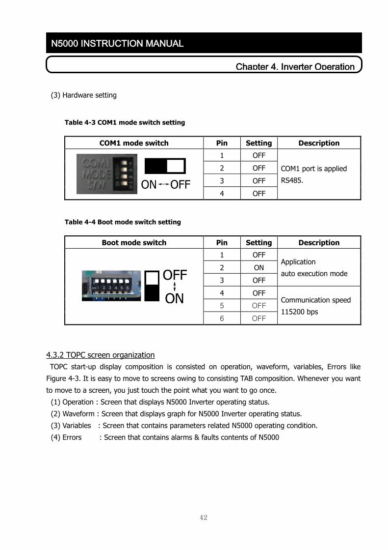
(3) Hardware setting
Table 4-3 COM1 mode switch setting
COM1 mode switch Pin Setting Description
1 OFF
COM1 port is applied
RS485.
2 OFF
3 OFF
4 OFF
Table 4-4 Boot mode switch setting
Boot mode switch Pin Setting Description
1 OFF Application
auto execution mode 2 ON
3 OFF
4 OFF Communication speed
115200 bps 5 OFF
6 OFF
4.3.2 TOPC screen organization
TOPC start-up display composition is consisted on operation, waveform, variables, Errors like
Figure 4-3. It is easy to move to screens owing to consisting TAB composition. Whenever you want
to move to a screen, you just touch the point what you want to go once.
(1) Operation : Screen that displays N5000 Inverter operating status.
(2) Waveform : Screen that displays graph for N5000 Inverter operating status.
(3) Variables : Screen that contains parameters related N5000 operating condition.
(4) Errors : Screen that contains alarms & faults contents of N5000

43
Chapter 4. Inverter Operation
N5000 INSTRUCTION MANUAL
Figure 4-3 TOPC Composition
4.3.3 Operation screen
Operation screen is the basic display of N5000 Inverter operator contains Input voltage, Output
voltage, Output current, Powercell DC link voltage, condition of Breaker, command/output
frequency, Digital I/O condition, Command frequency & Accel/Decel time setting and Run/Stop of
N5000 Inverter. So you can see all of the operating status of N5000 Inverter at a glance.
Figure 4-4. Operation Screen 1
(1) Communication LED (Figure 4-4, 1))
It shows whether the communication status between TOPC and Master controllers is good or
not. If communication is good, this LED is blinking regularly. If not, the LED is turned off or
not blinking regularly.

44
Chapter 4. Inverter Operation
N5000 INSTRUCTION MANUAL
(2) Fault indication (Figure 4-4, 2))
It is shown when a fault occurs. But if there is no fault or cleared in the errors screen, you
cannot see it. You can check the fault information on errors screen.
(3) Alarm indication (Figure 4-4, 3))
It is shown when a alarm occurs. But if there is no alarm, you cannot see it. You can check
the alarm information on errors screen.
(4) Run & Stop button (Figure 4-4, 4))
When you touch the Run & Stop button, N5000 executes the Run & Stop. When you touch the
Run button, if it does not meet conditions to operate the inverter uprightly, run command does
not work and pop-up window that is described the reason what it isn’t working should appear
(Figure 4-5). Run & Stop button is only shown on Operation screen & Waveform screen.
Figure 4-5. Notice window about not activatied condition to work
(5) Setting parameters related with N5000 operation (Figure 4-4, 5))
When you set or change parameters related with operation, you can see the 10KEY window by
touching a variable button or a variable lable (Figure 4-6).
The name, range, unit of selected variable for operation are shown in the 10KEY window.
You can input value what you want to set by using number or point buttons. If you touch
wrong button, you can erase value by touching CE button. To apply the value to system
parameters, you should touch the Enter button. If the value what you input is wrong (ex; over
range), it cannot apply and you can see pop-up window described the reason.
Figure 4-6. 10KEY window

45
Chapter 4. Inverter Operation
N5000 INSTRUCTION MANUAL
(6) Digital I/O Channel Display (Figure 4-4, 6))
N5000 Inverter has 16 channels digital input and 8 channels digital output. On/Off status of
the Digital I/O channel is displayed on operation screen and waveform screen of TOPC. And if
you touch digital display text ( , , ), the popup window will appear as Figure 4-7.
And you can confirm the status of digital I/O port and definitions. Touch the popup window, it
will disappear.
Figure 4-7. Digital I/O Channel Display
- Orange: digital input is activating, Gray (light out): not activating.
(7) Company logo & N5000 site information (Figure 4-4, 7))
If you touch the company logo twice continuously, ‘Configuration’ window will appear (Figure
4-8).
Figure 4-8. Setting & Mini keyboard
There are a program version of N5000 operator and Master. You can change the main
language on Language Selection menu. After selecting language, touch the ‘OK’ button. And
then all of the language will be changed to what you select. By modifing Site information label,
the text on upper left of TOPC will be changed. When you touch the label (Figure 4-8, 1)),

46
Chapter 4. Inverter Operation
N5000 INSTRUCTION MANUAL
‘Mini keyboard’ will appear and you can input what you want to write. Font Size and Fond
Aspect Ratio of TOPC also can be changeable. If you want to apply, touch ‘OK’ button. ‘Exit to
WinCE’ button is to back to TOPC OS default screen.
(8) Basic Screen Tab (Figure 4-4, 8))
Touch the text what you want to go to a specific screen, it will be displayed.
Figure 4-9. Operation Screen 2
(9) Command frequency & Output Frequency & Animation (Figure 4-9, ①)
Command frequency & Output frequency are displayed as Progress Bar to compare easily. It
displays animation that whether motor is rotating or not and rotating direction.
Table 4-5 Animation icon & description
Display Description
N5000 Stop.
No Rotating
N5000 Forward Rotating
Clockwise direction
N5000 Reverse Rotating
Counter-clockwise direction

47
Chapter 4. Inverter Operation
N5000 INSTRUCTION MANUAL
(10) Status of Breaker (Figure 4-9, ②)
It displays On/Off status of I/O Breaker & By-pass Breaker of N5000 Inverter.
1) Om status : Breaker TEXT & LED color is orange.
2) Off status : Breaker TEXT & LED color is gray.
(11) Input voltage (Figure 4-9, ③)
It displays Input voltage of N5000 Inverter
1) RS: RS line voltage as rms
2) ST: ST line voltage as rms
3) TR: TR line voltage as rms
(12) Cell DC-link voltage (Figure 4-9, ④)
It displays Power Cell DC Voltage of N5000 Inverter
1) Ux (x=1~10) : Power Cell DC voltage of the layer on U phase
2) Vx (x=1~10) : Power Cell DC voltage of the layer on V phase
3) Wx (x=1~10) : Power Cell DC voltage of the layer on W phase
(13) Output currents (Figure 4-9, ⑤)
It displays Output current of N5000 Inverter
1) U: U phase current as rms
2) V: V phase current as rms
3) W: W phase current as rms
(14) Output voltage (Figure 4-9, ⑥)
It displays Output voltage of N5000 Inverter.
1) UV: UV line voltage as rms
2) VW: VW line voltage as rms
3) WU: WU line voltage as rms
4.3.4 Waveform Screen
Waveform Screen displays Input/Output voltage, output rms current, motor speed and output
power through Scope Windows by real-time as Trace-data type. And, it displays Instant-Data type
simultaneously.

48
Chapter 4. Inverter Operation
N5000 INSTRUCTION MANUAL
Figure 4-10. Waveform screen
(1) Scope screen button (Figure 4-10. ①)
Scope window is set and displayed by scope window buttons. The functions of each button are
as follow Table 4-6.
Table 4-6 Scope window buttons
Display Description
PLAY button on scope window. When touching a play button,
displaying selected item as real-time trace-data type on scope
window.
STOP button on scope window. When touching a stop button, halting
all data on scope window.
Setting button on scope window. It is to set item, time, the number of
scope window. (Refer to (2) Scope setting).
(2) Scope setting (Figure 4-10. ①, ②)
When touching the scope setting button, it will display scope setting window to set scope
configuration. (Figure 4-11).

49
Chapter 4. Inverter Operation
N5000 INSTRUCTION MANUAL
Figure 4-11. Scope Configuration window
1) The number of scope window (Figure 4-11, ①)
The number of scope windows can be selected with 1 or 2 on ‘Count of scope window’
menu.
Figure 4-12. Th number of scope windows
2) Maximum value of X axis (Figure 4-11, ②)
X axis (Time) can be set as 1~10minutes. Set value is displayed on right below of window.

50
Chapter 4. Inverter Operation
N5000 INSTRUCTION MANUAL
3) Item x(x=0~5) selection (Figure 4-11, ③)
Item can be displayed by selecting item on Item x selection. Selectable item and display
type is described on table 3.
① Scope window ‘1’ (Upper scope window)
It displays items that are selected among “Item selection 0 ~ 2”.
(Item 3~5 is not displayed even if they are selected.)
② Scope window ‘2’ (Below scope window)
It displays items that are selected among “Item selection 3~5”.
Table 4-7 Selectable item type
Item Display type
N/A Not applicable
Output power N5000 inverter power is displayed with kW unit.
Speed Motor speed is displayed with RPM unit by encoder.
Without encoder, calculated motor speed is displayed.
Input voltage RS Input line voltage between R and S is displayed as RMS.
Input voltage ST Input line voltage between S and T is displayed as RMS.
Input voltage TR Input line voltage between T and R is displayed as RMS.
Output voltage UV Output line voltage between U and V is displayed as RMS.
Output voltage VW Output line voltage between V and W is displayed as RMS.
Output voltage WU Output line voltage between W and U is displayed as RMS.
Output current U Output current of U phase is displayed as RMS.
Output current V Output current of V phase is displayed as RMS.
Output current W Output current of W phase is displayed as RMS.
4) Maximum value of item x(x=0~5) (Figure 4-11, ④)
It is to set maximum value of selected item.

51
Chapter 4. Inverter Operation
N5000 INSTRUCTION MANUAL
4.3.5 Variables Screen
Variables screen is to set variables that are changeable according to inverter system, driving
sequence, motor control type. Moreover driving set variables can be downloaded and uploaded
(save and load). The number, name, applied value, master and slave set value of each variable is
displayed as type of List box.
Figure 4-13. Variables screen
The procedure to set variable is as below;.
1) Touch the code button what you want to set or adjust. (Figure 4-13, ③).
2) Touch the down-arrow button to find variable. (Figure 4-13, ⑤).
3) Touch the variable. (Figure 4-13, ④).
4) Set or adjust variable by 10KEY Screen. (Refer to 4.3.3 (5) to operate 10KEY).
(1) Code description window (Figure 4-13, ①)
There are 196 variables for inverter operation. It is useful to find variables which are classified
by below criteria (A~F codes). Each code description is displayed on (Figure 4-13, ①) when
code button (Figure 4-13, ③) is touched.
1) A Code : N5000 inverter basic setting variables
2) B Code : N5000 inverter analog I/O setting variables
3) C Code : N5000 inverter digital I/O setting variables
4) D Code : N5000 inverter alarm, fault level setting variables
5) E Code : N5000 inverter V/F control setting variables
6) F Code : N5000 inverter SLV/Vector control setting variables

52
Chapter 4. Inverter Operation
N5000 INSTRUCTION MANUAL
(2) Save file & load file (Figure 4-13, ②)
It is to save and load file data of N5000 inverter operating variables.
1) Save file
It is possible that file can be saved on memory in TOPC (Folder name ‘Flash Disk’) or
external memory such as USB-HOST on rear of TOPC and SD card through connector. (If
files are saved on other type memory except above type, files are deleted when TOPC is
restarted). The procedure of saving files is as follow table 4-8;
Table 4-8 Procedure of saving files
Procedure Description
↓
↓
① Touch file save button on variables
screen.
② Confirm saving folder path on ‘Save as’
③ Touch button ‘OK’ (2) on left fig.)
④ Progress Bar appears.
⑤ ‘Notice’ window appears and saving file
name also will be shown.
File name( 1)) is set automatically.
2) Load file
File cannot be loaded during inverter running. The procedure of loading saved variable is as
follow table 4-9.

53
Chapter 4. Inverter Operation
N5000 INSTRUCTION MANUAL
Table 4-9 Procedure of loading files
Procedure Description
↓
↓
⑥ Touch file load button on variables
screen.
① Confirm loading file path on ‘Open’.
② Touch button ‘OK’
③ Progress Bar appears.
④ On mode - N5000 MCU redundancy,
SLAVE MCU is loaded automatically.
⑤ ‘Notice’ window appears and loading file
name also will be shown.
(3) Code select button (Figure 4-13, ③)
Touch the code button to set and adjust variables. And then the variables for selected code
will appear in the list box (Figure 4-13, ④). The selected code button will be deactivated and
cannot be touched. Total Code button covers all variables from A code to F code
(4) List Box (Figure 4-13, ④)
When a code button is touched, the variables of code will be displayed on List Box. Each
variable has identification number that is displayed on “Number” column and variable name
that is displayed on “Variable Name” column. ‘Applied Value’ column means present setting
value with unit [A, V, Hz, etc] on N5000 inverter operation information. ‘MAS’ means Master
board on N5000 Main control part, ‘SLV’ means Slave board – redundant board.

54
Chapter 4. Inverter Operation
N5000 INSTRUCTION MANUAL
4.3.6 Errors Screen
Errors screen displays the contents of alarm and fault that is occured during N5000 running.
Alarm/fault’s reset is possible by Clear buttons. Time setting, fault information, running time and
initializing variable buttons are also displayed.
Figure 4-14. Errors screen
(1) Fault Content (Figure 4-14, ①)
Fault content displays N5000 operating informations at the time of fault and max. 64
informations can be saved. At first, the latest occured fault contents are displayed and can
move to previous faults by arrow button. When a fault occurred, confirm the reason of fault
and repair. And then touch the “Clear fault” to reset fault status. During fault status, it is
impossible to check the other number of fault.
1) Fault number : Number of latest fault is “1”. Fault numbering is inverse time order. To find
the other number, touch the arrow button.
2) Fault time : Fault occured time
3) Fault content: Describe a cause of N5000 fault
4) Cmd. Freq.: Display command frequency at the time of fault
5) Output Freq.: Display output frequency at the time of fault
6) Output voltage: Display output voltage at the time of fault
7) Output current : Display output current at the time of fault
8) Running time: Display running time from inverter running to fault
9) Inserting time: Main control part running time

55
Chapter 4. Inverter Operation
N5000 INSTRUCTION MANUAL
(2) Alarm content (Figure 4-14, ③)
Alarm content displays the alarm information. In case of alarm, alarm can be overlap and
overlapped alarm should be displayed. After confirming alarm, touch the alarm clear button
(Figure 4-14, ④) to reset alarm.
(3) Set time (Figure 4-14, ⑤)
Current time displays present time on N5000 inverter main control part and can be adjust by
Set Time buttons.
Figure 4-15. Set time window
Set Time window displays year/month/date/time (Figure 4-15). These parameters can be
adjusted on this window.
(4) Initialize (Figure 4-14, ⑥)
By Reset button, all variables, fault/alarm contents, running time etc. can be initialized in
initialization window (Figure 4-16).

56
Chapter 4. Inverter Operation
N5000 INSTRUCTION MANUAL
Fig. 4-16 Initialization
1) No Initialization: Do not initialize.
2) Faults Data : Initialize all fault contents.
3) Parameters : Initialize all parameters with default value. (Refer to Attachment 1.)
4) Operation Time : Initialize running time and inserting time
5) Total : Initialize all data - parameters, Fault data, operation time etc.

57
Chapter 4. Inverter Operation
N5000 INSTRUCTION MANUAL
4.4 Variable for inverter operation
Variables for inverter operation are changeable up to installation site condition and applicable
load of inverter system, operating sequence, motor control type. If each variable is set incorrectly,
it cannot be well operated and N5000 inverter system may be damaged.
There are 196 variables for inverter operation. Refer to attachment 1 to know name, min / max /
base value of each variables. It is useful to find variable which is classified by below criteria (A~F
codes).
A Code : N5000 inverter basic setting variables.
B Code : N5000 inverter analog I/O setting variables.
C Code : N5000 inverter digital I/O setting variables.
D Code : N5000 inverter alarm, fault level setting variables.
E Code : N5000 inverter V/F control setting variables.
F Code : N5000 inverter SLV/Vector control setting variables.
4.4.1 A code variables
A Code is composed with 26 basic variables. Each variable’s meaning is as below;
0) Command frequency
User can set command frequency value in the range of 0 ~ maximum frequency as [Hz] unit.
1) Acceleration time
Set time duration from 0Hz to base frequency as [Sec] unit. [Reference 1].
2) Deceleration time
Set time duration from base frequency to 0Hz as [Sec]. [Reference 1].

58
Chapter 4. Inverter Operation
N5000 INSTRUCTION MANUAL
[Reference 1]
Time
Output frequency
Base
frequency
Commend frequency
Accel time Decel time
Real accel time Real decel time
Relationship between acceleration, deceleration time and output frequency
Set values of acceleration and deceleration time are the time durations to reach base frequency from 0Hz and
0Hz from the base frequency. Therefore, real acceleration/deceleration time is smaller than the set value when
the command frequency is smaller than the base frequency.
[EXAMPLE]
• Base frequency: 60 Hz,
• Current output frequency: 0Hz,
• Command frequency: 40 Hz,
• Acceleration time: 30[Sec],
• Deceleration time: 30[Sec]
timeonacceleratifrequencybase
frequencyoutputcurrentfrequencycommandtimeonacceleratireal
Therefore, real acceleration time is 20[Sec].
3) Motor direction
Set rotational direction of motor. (Direction cannot be changed during running)
‘1’ – FWD : forward direction
‘2’ – REV : reverse direction
4) Test mode
Inverter can be operated even when CAN communication is abnormal.

59
Chapter 4. Inverter Operation
N5000 INSTRUCTION MANUAL
0: [Displays ‘OFF’] Inverter cannot be operated when CAN communication is abnormal.
1: [Displays ‘ON’] Inverter can be operated even when CAN communication is abnormal
[Reference] In site installation, for checking sequence between N5000 and SWGR, although
CAN communication is abnormal, it can be operated normally.
5) Inverter capacity
Set inverter capacity in [MVA] unit.
6) Input voltage
Set inverter input line voltage in [KV] unit
7) Operator selection
Select which operator sends command frequency and run / stop command.
‘0’ : [Displays ‘TOPC’] takes commands from TOPC. (Called as LOCAL mode)
‘1’ : [Displays ‘TM’] takes commands from external controller. (Called as ROMOTE mode)
‘2’ : [Displays ‘COM’] takes commands through N5000 MMI(RS-485 etc.)
8) N/A
9) Base frequency
Set base frequency. Usually rated frequency of the motor is set for the base frequency.
[Reference2].
10) Maximum frequency
Set maximum frequency of inverter output voltage. [Reference2].
[Reference 2]
Base frequency: the frequency that generates maximum output voltage. Usually rated frequency of
the motor is set as base frequency.
Maximum frequency: maximum frequency that can operate motor. Constant voltage is generated
beyond base frequency as shown below.
Max output
vlotage
Base frequency Max frequency
Relationship between base frequency and maximum frequency

60
Chapter 4. Inverter Operation
N5000 INSTRUCTION MANUAL
11) Controller selection
Set the operating method for motor.
0: [displays ‘V/F’] linear torque mode. [Reference 3]
1: [displays ‘T17’] reduced torque mode 1. [Reference 3]
2: [displays ‘T20’] reduced torque mode 2. [Reference 3]
3: [displays ‘SLV’] sensorless vector control mode.
4: [displays ‘VC’] vector control mode.
5: [displays ‘VF SC’] Slip frequency control mode.
[Reference 3]
Linear torque mode: output voltage is generated proportionally with the output frequency.
Max output
voltage
Base frequency Max frequency
V/F linear torque mode
Reduced torque mode: This mode is used when there is no need of intensive torque at low speed.
1) Reduced torque mode 1: generates output voltage with the curve of 1.7th power out of frequency.
2) Reduced torque mode 2: generates output voltage with the curve of 2.0th power out of frequency.
Max output
voltage
Base frequency Max frequency
V/F reduced torque mode

61
Chapter 4. Inverter Operation
N5000 INSTRUCTION MANUAL
12) Output voltage gain
Set the rate of output voltage in % when the output voltage frequency is the maximum
frequency.
13) Controller Mode
Select N5000 main controller mode among single or dual.
If N5000 main controller consists of one controller, set it 1. (Displays ‘single’).
If N5000 main controller consists of two controller, set it 2. (Displays ‘dual’).
14) Cell Number
Set the number of cell for one phase. If input voltage is 3300V class, set it 3 in this item. If
input voltage is 6600V class, set it 6 in this item.
[Caution] Controller power should be ‘ON→OFF→ON’ to apply values from 13) and 14) to the
system.
15) No-load current
Set the no-load motor current in [A] unit.
16) Motor rated voltage
Set the rated motor input line voltage in [kV] unit.
17) Motor pole
Set the number of poles of motor.
18) Motor rated current
Set the rated motor current in [A] unit.
19) Motor rated capacity
Set the rated motor capacity in [MVA] unit.
20) Soft LOCK
It is to prevent from modifying data.
‘0’ input [Displays ‘OFF’]: Not use Soft lock.
‘ 1’ input [Displays ‘ON’]: Use soft lock. All variables except for command frequency,
acceleration time, deceleration time and soft lock cannot be changeable with TOPC.
21) Initial Mode
‘0’ input[Displays ‘No Initialization’]: No initialization.
‘1’ input [Displays ‘Faults Data’]: Initializes history of system faults and alarms.
‘2’ input [Displays ‘Parameters’]: Initializes variables for operation to default values.
‘3’ input [Displays ‘Operation Time’]: Initializes running and inserting time.
‘4’ input [Displays ‘Total’]: Initializes all.
22) N/A
23) Ex Comm. Set
It is to set communication protocol between N5000 and external device.
‘0’ input [Displays ‘N5000MMI’]: Communication with only N5000 MMI

62
Chapter 4. Inverter Operation
N5000 INSTRUCTION MANUAL
‘1’input [Displays ‘ModBus’]: Communication with Modbus RTU protocol
‘2’input [Displays ‘Tr. LAB’] : N/A
24) Ex Comm. Baudrate
It is to set Baudrate for external communication.
‘0’ input[Displays ‘9600’]: Baudrate 9600bps.
‘1’ input [Displays ‘19200’]: Baudrate 19200bps.
‘2’ input [Displays ‘38400’]: Baudrate 38400bps.
25) Ex Comm. ID
It is to set ID for External communication setting.
26) Stop Method
Set method for inverter stoping.
‘0’ input [Displays ‘FreeRun Stop’]: Free-run stop.
‘1’ input [Displays ‘Deceleration Stop’]: Deceleration stop.
27) N/A
4.4.2 B code variables
B Code is composed with 42 basic variables. Each variable’s meaning is as below;
28) External Cmd Frequency
There are 4 external analog channels to set command frequency and get external signals. This
variable chooses one channel as a command frequency terminal when command frequency is
set by external analog input.
29) Start frequency
Set the start frequency of command frequency in [Hz] unit when the command frequency is
determined by the external analog input. [Reference 4]
30) End frequency
Set the end frequency of command frequency in [Hz] unit when the command frequency is
determined by the external analog input. [Reference 4].
31) Start rate
Set the start voltage of command frequency when the command frequency is determined by
the external analog input [Reference 4].
32) End rate
Set the end voltage of command frequency when the command frequency is determined by
the external analog input. [Reference 4].
33) Starting method selection
Select starting method when the command frequency is determined by the external analog
input.

63
Chapter 4. Inverter Operation
N5000 INSTRUCTION MANUAL
0: [Displays ‘Code’] If command frequency is in the range of 0 ~ start rate, TOPC outputs
‘start frequency’ as command frequency.
1: [Displays ‘0Hz’] If command frequency is in the range of 0 ~ start rate, TOPC outputs ‘0Hz’
as command frequency.
[Reference 4]
When starting method selection ((6)) is ‘0’.
100%
10V or
20mA
0V or
4mA
Output frequency (Hz)
Commend
frequency(%)
Max freq.
End freq.
Start freq.
Start
ratio
End
ratio
When starting method selection ((6)) is ‘1’.
Output frequency (Hz)
100%
Commend
frequency(%)
Max freq.
End freq.
Start freq.
Start
ratio
End
ratio
10V or
20mA
0V or
4mA

64
Chapter 4. Inverter Operation
N5000 INSTRUCTION MANUAL
34) N/A
35) N/A
36) N/A
37) Vrs scale
Set scale of resistor sensor for input line voltage of R-S
38) Vst scale
Set scale of resistor sensor for input line voltage of S-T
39) Vtr scale
Set scale of resistor sensor for input line voltage of T-R.
40) Iu scale
Set scale of output current for U phase
41) Iv scale
Set scale of output current for V phase
42) Iw scale
Set scale of output current for W phase
43) Vuv scale
Set scale of resistor sensor for output line voltage of R-S
44) Vvw scale
Set scale of resistor sensor for output line voltage of S-T
45) Vwu scale
Set scale of resistor sensor for output line voltage of T-R
46~49) AnalogOut Ch.x(x=1~4) Selection
Set the signal of each channel for analog output terminal (x).
‘0’ input[Displays ‘N/A’]: Not applicable this channel.
‘1’ input [Displays ‘command frequency’]: Set signal command frequency the channel
‘2’ input [Displays ‘output frequency’]: Set signal output frequency the channel.
‘3’ input [Displays ‘motor speed’]: Set signal motor speed the channel.
‘4’ input [Displays ‘output voltage’]: Set signal output voltage the channel.
‘5’ input [Displays ‘output current’]: Set signal output current the channel.
‘6’ input [Displays ‘output power’]: Set signal output power the channel.
50~53) AnalogOut Ch.x(x=1~4) Gain
Set the gain of each channel for analog output terminal (x).

65
Chapter 4. Inverter Operation
N5000 INSTRUCTION MANUAL
[Reference 5]
→ The gain is ‘a’ of set channel(AOx, x=1~4)
Set signal Output value
4mA(0V) 20mA(10V)
Command
frequency[Hz]
0 Max frequency*
Output frequency[Hz] 0 Min frequency*
Motor speed[RPM] 0 Motor max speed**
Output current[A] 0 Motor rated
current*
Output voltage[kV] 0 Motor rated
voltage*
Output power[kW] 0 Inverter capacity*
* Set value of each variable
** Motor max speed = (120ⅹMax frequency) / Motor poles
[Reference 5 example]
① Output value when variables are set as below;
▷ AO1 channel select : ‘1’ ▷ AO1 Channel select: ‘1.2’
▷ Max frequency: 60[Hz]
→Output value
4mA(0V) 20mA(10V)
0 72[Hz](: 60ⅹ1.2)*
* 60(: Max frequency)ⅹ1.2(: AO1 gain)
② AOx channel selection and the gain calculation method of AOx for setting case as
below;
▷ Max frequency: 60[Hz]
▷ Analog output terminal 2 channels are set as output frequency and 20[mA],
100[Hz]
→ AO2 channel select : Set as ‘2’
→ AO2 gain: set as ‘1.67’(100/60(Max frequency)=1.67)

66
Chapter 4. Inverter Operation
N5000 INSTRUCTION MANUAL
54,56,58,60) AnalogIn Ch.x(x=1~4) Gain
Set the gain of analog input terminal signal of the channel(x).
55,57,59,61) AnalogIn Ch.x(x=1~4) offset
Set the offset of analog input terminal signal of the channel(x).
62) PID function Selection
Set whether PID function use or not. [Referece 6].
‘0’ input[Displays ‘OFF’]: Not use PID function .
‘1’ input [Displays ‘ON’]: Use PID function.
63) PID P gain
In the case of appling PID function, set gain value of P-Term [Reference 6].
64) PID I gain
In the case of appling PID function, set gain value of I-Term [Reference 6].
65) PID D gain
In the case of appling PID function, set gain value of D-Term [Reference 6].
66) PID Reference signal
In the case of appling PID function, set analog input channel for reference signal.
[Reference 6].
‘0’ input[Displays ‘0CH’]: Not use PID reference signal.
‘1’ input [Displays ‘1CH’]: Set channel 1 as PID reference signal.
‘2’ input [Displays ‘2CH’]: Set channel 2 as PID reference signal.
‘3’ input [Displays ‘3CH’]: Set channel 3 as PID reference signal.
‘4’ input [Displays ‘4CH’]: Set channel 4 as PID reference signal.
67) PID Feedback Signal
Feedback signal is received through analog input terminals. Select one analog channel for
feedback signal [Reference 6].
‘0’ input[Displays ‘0CH’]: Not use PID feedback signal.
‘1’ input [Displays ‘1CH’]: Use CH1 channel for PID Feedback signal.
‘2’ input [Displays ‘2CH’]: Use CH2 channel for PID Feedback signal.
‘3’ input [Displays ‘3CH’]: Use CH3 channel for PID Feedback signal.
‘4’ input [Displays ‘4CH’]: Use CH4 channel for PID Feedback signal.
68) External Cmd Frequency 2
If there are 2 external devices to send command frequency through analog input terminal,
select the signal channel for the second command frequency.
‘0’ input[Displays ‘0CH’]: Not use External command channel 2.
‘x(x=1~4)’ input [Displays ‘xCH’]: set channel x as external command channel 2.

67
Chapter 4. Inverter Operation
N5000 INSTRUCTION MANUAL
[Reference 6]
PID function controls oil flow, wind flow, and pressure for motor.
Basic composition of PID control
TargetValue Kp +
K is+ Kd
sInverter Control M
Sensor
FeedBack
Basic composition of PID control
PID operation
1) P (Proportional) operation: controlling amount is proportional to the objective value.
Target
ControlSmall
Big
Small
Big
P Gain P Gain
2) I (Integral) operation: controlling amount increases linearly as the time increases.
Target
ControlSmall
Big
I Gain I Gain
Small
Big
3) D (Derivative) operation: increase of controlling amount is proportional to the changing
ratio of objective value.
Target
ControlSmall
Big
D Gain
Small
Big
D Gain
69) Transformer temperature channel
Set external input terminal for inverter input multi-phase transformer temperature sensor
signal.
‘0’ input[Displays ‘0CH’]: Not use transformer temperature channel.
‘x(x=1~4)’ input [Displays ‘xCH’]: set channel x as Transformer temperature channel.
70) N/A

68
Chapter 4. Inverter Operation
N5000 INSTRUCTION MANUAL
4.4.3 C code variables
C Code is composed with 26 basic variables. Each variable meaning is same as below;
71~81) DigitalIn x(x=1~11)
It displays predefined digital input terminals CH1~11, the variables cannot be set and
changed. Each input terminal is “ON” when it is activating, “OFF” when it is not activating.
There is definition of input terminals as below;
① Input terminal 1: N5000 Inverter Run command
② Input terminal 2: Emergency stop signal
③ Input terminal 3: Trip reset signal
④ Input terminal 4: N5000 Inverter mode signal
⑤ Input terminal 5: External trip signal
⑥ Input terminal 6: Internal trip signal
⑦ Input terminal 7: AC power condition signal
⑧ Input terminal 8: DC power condition signal
⑨ Input terminal 9: Input VCB closed signal
⑩ Input terminal 10: Output VCB closed signal
⑪ Input terminal 11: Fan power condition signal
82~86) Input terminal x(x=12~16)
Set signals for each input terminals CH12~16. Each input terminal is “ON” when it is activating,
“OFF” when it is not activating.
‘0’ Input[Displays ‘N/A’]: N/A terminal
‘1’ Input [Displays ‘Transformer over-temperature trip’]: Set as transformer over-temperature
trip.
‘2’ Input [Displays ‘Transformer over-temperature alarm’]: Set as transformer over-
temperature alarm.
‘3’ Input [Displays ‘Door switch’]: Set as trip during panel door opening.
‘4’ Input [Displays ‘Flow switch’]: Set as flow switch.
‘5’ Input [Displays ‘K3 status’]: Set as bypass breaker status.
‘6’ Input [Displays ‘External fault 2’]: Set as External fault 2.
‘7’ Input [Displays ‘parallel drive’]: Set as Parallel driving inverter use/not-use.
‘8’ Input [Displays ‘CMD Frequency Selection’]: Select command frequency input channel.
‘9’ Input [Displays ‘Sync meter’]: Set as signal from synchro-meter.
‘10’ Input [Displays ‘Sync mode’]: Set as mode selection signal of synchro-changeover.
‘11’ Input [Displays ‘Sync run’]: Set as start signal of synchro-changeover.

69
Chapter 4. Inverter Operation
N5000 INSTRUCTION MANUAL
87~94) DigitalOut x(x=1~8)
Set signals for each input terminals CH1~8. Each input terminal is “ON” when it is activating,
“OFF” when it is not activating.
‘1’ Input [Displays ‘N/A’]: Not applicable
‘2’ Input [Displays ‘Ready’]: Set as a ready signal.
‘3’ Input [Displays ‘Running’]: Set as an inverter running.
‘4’ Input [Displays ‘Fault’]: Set as an fault signal.
‘5’ Input [Displays ‘Alarm’]: Set as a alarm signal.
‘6’ Input [Displays ‘Emergency’]: Set as an emergency push button
‘7’ Input [Displays ‘Stop 1s’]: Set as a stop signal during 1 second.
‘8’ Input [Displays ‘Cell Bypass Operation’]: Set as a Cell bypass use/not-use.
‘9’ Input [Displays ‘TOPC/REMOTE’]: Select mode which TOPC or REMOTE.
‘10’ Input [Displays ‘K1 Off P(2sec.)’]: Set as an input VCB OFF command signal during
synchro-changeover.
‘11’ Input [Displays ‘K2 Off P(2sec.)’]: Set as an output VCB OFF command signal during
synchro-changeover.
‘12’ Input [Displays ‘K3 Off P(2sec.)’]: Set as a bypass VCB OFF command signal during
synchro-changeover.
‘13’ Input [Displays ‘K3 On P(2sec.)’]: Set as a bypass VCB ON command signal during
synchro-changeover.
‘14’ Input [Displays ‘Reach Freq. level’]: Select a reach frequency level use/not-use.
95) Encoder PPR
In the case of appling motor speed sensor, set a PPR (Pulse per Revolution) of speed sensor.
‘0’ means not-use speed sensor.
96) Reach Freq. level
When output frequency exceeds ‘reach frequency level’, DO terminal outputs ‘ON’ signal as
‘reach frequency signal’. [Reference7]
[Reference7]
Reach frequency level
Output frequency
Digital Output OFF ON OFF

70
Chapter 4. Inverter Operation
N5000 INSTRUCTION MANUAL
97~104) N/A
4.4.4 D code variables
D Code is composed with 26 basic variables. Each variable meaning is as below;
105) Speed Loss Flt/Alm
Set as Fault or alarm during the loss of external command frequency signal.
‘0’ input[Displays ‘Fault’]: During the loss of command frequency, treated as fault .
‘1’ input[Displays ‘Alarm’]: During the loss of command frequency, treated as alarm.
106) Restart Mode
This function is to restart during motor free-run after inverter is stopped or input voltage-sag
is occured.
‘0’ input[Displays ‘OFF’]: Not use restart function.
‘1’ input[Displays ‘ON’]: Use restart function.
107) Interrupt Permit Time
Interrupt permit time is the waiting time for the recovery of input voltage after input voltage
sagging. On restart mode, if input voltage is recovered within interrupt permit time, N5000
inverter will restart. Set as unit [sec].
108) Electric Thermal Mode
Set use/not-use of electronic thermal mode.
‘0’ input[Displays ‘OFF’]: Not use electronic thermal mode.
‘1’ input[Displays ‘ON’]: Use electronic thermal mode.
109) Electric thermal Level
In the case of appling electronic thermal function, set trip base value. Normally it is based on
motor rated current (100%).
110) Electric Thermal Character
Set characteristics of electronic thermal whether constant torque control or reduced torque
control.
‘0’ input[Displays ‘CTC’]: Set as constant torque control.
‘1’ input[Displays ‘RTC’]: Set as reduced torque control.
111) Over Current Limit Level
Over current limit level (OC level) is to set inverter over current level. It is based on inverter
rated current and set by [%].
112) Voltage Limit Level
Voltage limit level is to set over voltage level. It is based on power cell DC link voltage. DC link
voltage is 850[V] at 100[%]. [Reference 8]

71
Chapter 4. Inverter Operation
N5000 INSTRUCTION MANUAL
113) Current Limit Level
Current limit level is set as [%] based on motor rated current [100%]. [Reference 8].
114) Cell Bypass Function
Set use/not-use of cell bypass.
‘0’ input[Displays ‘OFF’]: Not use cell bypass.
‘1’ input[Displays ‘Balance’]: Use cell bypass with balance function.
‘2’ input[Displays ‘Unbalance’]: Use cell bypass with unbalance function.
115) Door Open Fault
Set for disable some protections of inverter fault.
‘0’ input[Displays ‘OFF’]: No disable fault protection.
‘1’ input[Displays ‘ON’]: Disable initial CAN communication alarm, Door open fault protection.
[Reference 8]
Relation voltage limit level and current limit level with output current as
below;
Relation voltage, current limit level with output current
Voltage limits level
Current limits level
DC-LINK Voltage
Output current
Output frequency
Commend frequency

72
Chapter 4. Inverter Operation
N5000 INSTRUCTION MANUAL
116) Restart Output Volt. Acl/Dcl
On restart mode, it describes output voltage’s acceleration/deceleration gradient and set as
[%] of acceleration time in A code variable.
117) Restart Output freq. Acl/Dcl
On restart mode, it describes output frequency’s acceleration/deceleration gradient and set as
[%] of deceleration time in A code variable.
118) Restart Permission Back EMF(Back ElectroMotive Force)
When Back EMF is detected at beginning of restarting, restart mode will be waiting until Back
EMF is lower than permission Back EMF value [%] and inverter will restart.
119) Restart Test Mode
Before use the restart function, set for testing restart parameter.
120) Restart P gain
Set restart proportional gain value for accurate restart.
121) Restart I gain
Set restart integral gain value for accurate restart.
122) Re-Restart Permit Time
On restart mode, if restart function cannot be worked within Re-Restart permit time, inverter
is restarted on 0Hz automatically. Permit time is set by [%] of motor free-run duration.
123) Power Fail Mode
Set use/not-use of power fail mode.
On power fail mode, inverter is to stop during input voltage’s blackout and restart after input
voltage’s recovery.
124) Power Fail Permit Time
Power fail permit time is the waiting time for the recovery of input voltage after input voltage’s
blackout. On power fail mode, if input voltage is recovered within power fail permit time,
N5000 inverter will restart. Set as unit [sec].
4.4.5 E code variables
E Code for inverter V/F control is composed with 18 basic variables. Each variable’s meaning is as
below;
125) Boost Mode
Set use/not-use boost mode function. [Reference 9]
‘0’ input[Displays ‘OFF’]: Not use boost mode.
‘1’ input[Displays ‘ON’]: Use boost mode.

73
Chapter 4. Inverter Operation
N5000 INSTRUCTION MANUAL
126) Boost Voltage
Boost voltage is set as [%] based on output voltage(100%). [Reference 9]
127) Boost frequency
Boost frequency is set as [%] based on base frequency(100%). [Reference 9]
[Reference 9]
Manual torque boost mode: Relationship among boost voltage, boost frequency,
and output voltage of manual boost mode is shown as below;
Output voltage
Base freq.
(100%)
Frequency
100%
Boost
voltage
Boost
Freq.
Boost mode
128) Freq. Upper Limit
Command frequency should not be set over frequency upper limit value [Hz].
129) Frequency Lower Limit
Command frequency should not be set under frequency lower limit value [Hz].
130,132,134) Jump Frequency x(x=1~3)
Set center of frequency x(x=1~3)[Hz] to skip the output frequency. [Reference 10].
131,133,135) Jump Frequency Width x(x=1~3)
Set half of frequency x(x=1~3) width [Hz] for jump. [Reference 10].

74
Chapter 4. Inverter Operation
N5000 INSTRUCTION MANUAL
[Reference 10]
Equipments themselves have the specific resonance frequencies. If inverter
chooses resonance frequency of installed motor as the rotating frequency of
motor, the motor can severely be damaged. So N5000 prevents the resonating
phenomenon by jumping the resonance frequency of the motor.
-Frequency jump: Center frequency for jumping (=resonance frequency)
-Frequency jump width: 1/2 frequency width of jumping width.
Output
frequency
Frequency commend
Jump freq.1
Jump freq.2
Jump freq.3
Jump freq. width
Jump frequency
Relationship between frequency jump and output frequency
136) SC Proportional Gain
On slip frequency control mode, set proportional gain.
137) SC Integral Gain
On slip frequency control mode, set integral gain.
138) Acceleration pattern
Set output frequency and output voltage accelerating pattern corresponding to load.
[Reference 10].
‘0’ input[Displays ‘Linear’]: Set acceleration pattern as linear.
‘1’ input[Displays ‘S curve’]: Set acceleration pattern as S curve.
‘2’ input [Displays ‘U curve’]: Set acceleration pattern as U curve.
‘3’ input [Displays ‘RU curve’]: Set acceleration pattern as RU curve.

75
Chapter 4. Inverter Operation
N5000 INSTRUCTION MANUAL
139) Deceleration Pattern
Set output frequency and output voltage decelerating pattern corresponding to load.
[Reference 11].
‘0’ input[Displays ‘Linear’]: Set deceleration pattern as linear.
‘1’ input[Displays ‘S curve’]: Set deceleration pattern as S curve.
‘2’ input [Displays ‘U curve’]: Set deceleration pattern as U curve.
‘3’ input [Displays ‘RU curve’]: Set deceleration pattern as RU curve.
[Reference 11]
Relation Acceleration and Deceleration pattern with output frequency is as below;
시간
출력 주파수
시간
시간 시간
지령 주파수
(a)
(c)
(b)
(d)
Accel / Decel pattern
(a) Accel/decal pattern is set as ‘Linear’
(b) Accel/decal pattern is set as ‘S curve’
(c) Accel/decal pattern is set as ‘U curve’
(d) Accel/decal pattern is set as ‘RU curve’
140) Output GND Level
When the sum of instantaneous 3 phase output current is over output ground level [%] of
motor rated current, inverter trip is activated. (Normal case is instantaneous 3 phase current is
‘zero’)
141) Input OV Level
When instantaneous inverter input voltage is over input over voltage level [%], inverter trip is
Output frequency command frequency
Time
Time Time
Time

76
Chapter 4. Inverter Operation
N5000 INSTRUCTION MANUAL
activated.
142) Input UnVal Level
When 1 phase instantaneous input voltage is over input unbalance level [%] of inverter rated
voltage, inverter trip is activated.
4.4.6 F code variables
F Code for SLV or Vector control of inverter is composed with 39 basic variables. They are not
handle with this manual because these codes are set by only HHI engineer.

77
Chapter 4. Inverter Operation
N5000 INSTRUCTION MANUAL
[Attachment 1] N5000 variables list -1
No. Code Variables Range
Default Unit Be able to change
on run Min Max
0
A
Command Frequency 0.0 120.0 0.0 Hz
1 Acceleration Time 1 3600 120 초
2 Deceleration Time 1 3600 120 초
3 Motor Direction 1 2 1 - ⅹ
4 Test Mode 0 1 0 - ⅹ
5 Inverter Capacity 0.001 32.000 1.00 MVA ⅹ
6 Input Voltage 0.001 32.000 6.6 kV ⅹ
7 Operator Selection 0 2 0 - ⅹ
8 N/A - - - - -
9 Base Frequency 30.0 120.0 60.0 Hz ⅹ
10 Maximum Frequency 30.0 120.0 60.0 Hz ⅹ
11 Controller Selection 0 5 0 - ⅹ
12 Output Voltage Gain 20.0 100.0 100.0 % ⅹ
13 Controller Mode 1 2 2 - ⅹ
14 Cell Number 1 5 5 - ⅹ
15 No Load Current 0.1 999.9 29.1 A ⅹ
16 Motor Rated Voltage 0.001 32.000 6.600 kV ⅹ
17 Motor Pole 0 99 6 - ⅹ
18 Motor Rated Current 0.1 999.9 87.4 A ⅹ
19 Motor Rated Capacity 0.001 32.000 1.00 MW ⅹ
20 Soft Lock 0 1 0 - -
21 Initial Mode 0 4 0 - ⅹ
22 N/A - - - - -
23 Ex Comm. Set 0 2 0 - ⅹ
24 Ex Comm. Baudrate 0 2 1 - ⅹ
25 Ex Comm. ID 1 100 1 - ⅹ
26 Stop Method 0 1 0 - ⅹ
27 - N/A - - - - -
28
B
External Cmd Frequency 0 4 1 CH. ⅹ
29 Start Frequency 0.0 30.0 0.0 Hz ⅹ
30 End Frequency 30.0 120.0 60.0 Hz ⅹ
31 Start Rate 0 100.0 2.0 % ⅹ
32 End Rate 0 100.0 98.0 % ⅹ
33 Starting Method Selection 0 1 1 - ⅹ

78
Chapter 4. Inverter Operation
N5000 INSTRUCTION MANUAL
[Attachment 1] N5000 variables list -2
No. Code Variables Range
Default Unit Be able to change
on run Min Max
34
B
N/A - - - - -
35 N/A - - - - -
36 N/A - - - - -
37 Vrs Scale 0.01 30.0 1.0 - ⅹ
38 Vst Scale 0.01 30.0 1.0 - ⅹ
39 Vtr Scale 0.01 30.0 1.0 - ⅹ
40 Iu Scale 0.1 3000.0 1.0 - ⅹ
41 Iv Scale 0.1 3000.0 1.0 - ⅹ
42 Iw Scale 0.1 3000.0 1.0 - ⅹ
43 Vuv Scale 0.1 5000.0 1.0 - ⅹ
44 Vvw Scale 0.1 5000.0 1.0 - ⅹ
45 Vwu Scale 0.1 5000.0 1.0 - ⅹ
46 AnalogOut Ch.1 Selection 0 6 0 - ⅹ
47 AnalogOut Ch.2 Selection 0 6 0 - ⅹ
48 AnalogOut Ch.3 Selection 0 6 0 - ⅹ
49 AnalogOut Ch.4 Selection 0 6 0 - ⅹ
50 AnalogOut Ch.1 Gain 0.00 10.00 1.00 - ⅹ
51 AnalogOut Ch.2 Gain 0.00 10.00 1.00 - ⅹ
52 AnalogOut Ch.3 Gain 0.00 10.00 1.00 - ⅹ
53 AnalogOut Ch.4 Gain 0.00 10.00 1.00 - ⅹ
54 AnalogIn Ch.1 Gain 0.00 10.00 1.00 - ⅹ
55 AnalogIn Ch.1 Offset 0 2000 384 - ⅹ
56 AnalogIn Ch.2 Gain 0.00 10.00 1.00 - ⅹ
57 AnalogIn Ch.2 Offset 0 2000 384 - ⅹ
58 AnalogIn Ch.3 Gain 0.00 10.00 1.00 - ⅹ
59 AnalogIn Ch.3 Offset 0 2000 384 - ⅹ
60 AnalogIn Ch.4 Gain 0.00 10.00 1.00 - ⅹ
61 AnalogIn Ch.4 Offset 0 2000 384 - ⅹ
62 PID Function Selection 0 1 0 - ⅹ
63 PID P Gain 0.1 10.0 1.0 -
64 PID I Gain 0.0 3600.0 1.0 -
65 PID D Gain 0.0 100.0 0.0 -
66 PID Reference Signal 0 4 0 - ⅹ
67 PID Feedback Signal 0 4 0 - ⅹ

79
Chapter 4. Inverter Operation
N5000 INSTRUCTION MANUAL
[Attachment 1] N5000 variables list -3
No. Code Variables Range
Default Unit Be able to change
on run Min Max
68 B
External Cmd Frequency2 0 4 0 CH- ⅹ
69 Tr. Temp. Ch. 0 4 0 CH ⅹ
70 - N/A - - - - -
71
C
DigitalIn 1 - - 0 - ⅹ
72 DigitalIn 2 - - 1 - ⅹ
73 DigitalIn 3 - - 2 - ⅹ
74 DigitalIn 4 - - 3 - ⅹ
75 DigitalIn 5 - - 4 - ⅹ
76 DigitalIn 6 - - 5 - ⅹ
77 DigitalIn 7 - - 6 - ⅹ
78 DigitalIn 8 - - 7 - ⅹ
79 DigitalIn 9 - - 8 - ⅹ
80 DigitalIn 10 - - 9 - ⅹ
81 DigitalIn 11 - - 10 - ⅹ
82 DigitalIn 12 0 11 0 - ⅹ
83 DigitalIn 13 0 11 0 - ⅹ
84 DigitalIn 14 0 11 0 - ⅹ
85 DigitalIn 15 0 11 0 - ⅹ
86 DigitalIn 16 0 11 0 - ⅹ
87 DigitalOut 1 1 14 2 - ⅹ
88 DigitalOut 2 1 14 3 - ⅹ
89 DigitalOut 3 1 14 4 - ⅹ
90 DigitalOut 4 1 14 5 - ⅹ
91 DigitalOut 5 1 14 6 - ⅹ
92 DigitalOut 6 1 14 1 - ⅹ
93 DigitalOut 7 1 14 1 - ⅹ
94 DigitalOut 8 1 14 1 - ⅹ
95 Encoder PPR 0 65535 0 - ⅹ
96 Reach Freq. Level 0.1 100.0 100.0 % ⅹ
97 N/A - - - - -
98 N/A - - - - -
99 N/A - - - - -
100 N/A - - - - -
101 N/A - - - - -

80
Chapter 4. Inverter Operation
N5000 INSTRUCTION MANUAL
[Attachment 1] N5000 variables list -4
No. Code Variables Range
Default Unit Be able to change
on run Min Max
102
-
N/A - - - - -
103 N/A - - - - -
104 N/A - - - - -
105
D
Speed Loss Flt/Alm 0 1 0 - ⅹ
106 Restart Mode 0 1 0 - ⅹ
107 Interrupt Permit Time 1 18000 1 Sec ⅹ
108 Electric Thermal Mode 0 1 1 - ⅹ
109 Electric Thermal Level 20.0 120.0 100.0 %
110 Electric Thermal Character 0 1 0 - ⅹ
111 Over Current Limit Level 80.0 180.0 120.0 % ⅹ
112 Voltage Limit Level 80.0 150.0 123.0 % ⅹ
113 Current Limit Level 80.0 150.0 120.0 % ⅹ
114 Cell Bypass Function 0 2 0 - ⅹ
115 Door Open Fault 0 1 0 - ⅹ
116 Restart Output Volt. Acl/Dcl 0.01 200.00 10.00 % ⅹ
117 Restart Output Freq.
Acl/Dcl
0.01 200.00 50.00 % ⅹ
118 Restart Permission Back
EMF
0.1 100.0 5.0 % ⅹ
119 Restart Test Mode 0 1 0 - ⅹ
120 Restart P Gain 0.01 327.00 4.00 - ⅹ
121 Restart I Gain 0.1 3270.0 056.0 - ⅹ
122 Re-Restart Permit Time 20 100 50 % ⅹ
123 Power Fail Mode - - - - ⅹ
124 Power Fail Permit Time - - - - ⅹ
125
E
Boost Mode 0 1 0 - ⅹ
126 Boost Voltage 0.0 20.0 1.0 %
127 Boost Frequency 0.0 50.0 5.0 %
128 Freq. Upper Limit 0.0 120.0 60.0 Hz ⅹ
129 Freq. Lower Limit 0.0 120.0 0.0 Hz ⅹ
130 Jump Frequency 1 0.0 120.0 0.0 Hz ⅹ
131 Jump Frequency Width 1 0.0 10.0 0 Hz ⅹ
132 Jump Frequency 2 0.0 120.0 0.0 Hz ⅹ
133 Jump Frequency Width 2 0.0 10.0 0 Hz ⅹ
134 Jump Frequency 3 0.0 120.0 0.0 Hz ⅹ
135 Jump Frequency Width 3 0.0 10.0 0 Hz ⅹ

81
Chapter 4. Inverter Operation
N5000 INSTRUCTION MANUAL
[Attachment 1] N5000 variables list -5
No. Code Variables Range
Default Unit Be able to change
on run Min Max
136
E
SC Proportional Gain 0.00 327.00 0.00 - ⅹ
137 SC Integral Gain 0.00 327.00 0.00 - ⅹ
138 Acceleration Pattern 0 3 0 - ⅹ
139 Deceleration Pattern 0 3 0 - ⅹ
140 Output GND Level 30.0 120.0 80.0 % ⅹ
141 Input OV Level 120.0 180.0 130.0 % ⅹ
142 Input UnVal. Level 20.0 120.0 35.0 % ⅹ
143 N/A - - - - -
144 N/A - - - - -
145 N/A - - - - -
146 N/A - - - - -
147 N/A - - - - -
148 N/A - - - - -
149
F
Sensorless Gain 0.01 327.00 50 - ⅹ
150 Slip proportional Gain 0.01 327.00 0.01 - ⅹ
151 Slip Integral Gain 0.01 327.00 1.00 - ⅹ
152 Current Response Gain 0.01 99.99 1.00 - ⅹ
153 Current proportional Gain 0.00 327.00 0.00 - ⅹ
154 Current Integral Gain 0.00 327.00 0.00 - ⅹ
155 Flux Response Gain 0.001 9.999 1.000 - ⅹ
156 Flux Proportional Gain 0.01 99.99 1.00 - ⅹ
157 Flux Integral Gain 0.01 99.99 1.00 - ⅹ
158 Speed Response Gain 0.01 99.99 1.00 - ⅹ
159 Speed Proportional Gain 0.00 327.00 0.00 - ⅹ
160 Speed Integral Gain 0.00 327.00 0.00 - ⅹ
161 SLV_CC Response Gain 0.01 99.99 1.00 - ⅹ
162 SLV_CC Proportional Gain 0.01 99.99 1.00 - ⅹ
163 SLV_CC Integral Gain 0.01 99.99 1.00 - ⅹ
164 MRAS Proportional Gain 0.01 99.99 1.00 - ⅹ
165 MRAS Integral Gain 0.01 99.99 1.00 - ⅹ
166 ASO Proportional Gain 0.01 99.99 1.00 - ⅹ
167 ASO Integral Gain 0.01 99.99 1.00 - ⅹ
168 ASO Matrix Gain 0.01 1.99 1.00 - ⅹ
169 SLV_Wr Response Gain 0.01 99.99 1.00 - ⅹ

82
Chapter 4. Inverter Operation
N5000 INSTRUCTION MANUAL
[Attachment 1] N5000 variables list -6
No. Code Variables Range
Default Unit Be able to change
on run Min Max
170
F
-
SLV_Wr Propotional Gain 0.01 99.99 1.00 - ⅹ
171 SLV_Wr Integral Gain 0.01 99.99 1.00 - ⅹ
172 Stator Resistor 0.001 32.000 0.001 Ω ⅹ
173 Rotor Resistor 0.001 32.000 0.001 Ω ⅹ
174 Stator Inductance 0.001 32.000 0.001 H ⅹ
175 Rotor Inductance 0.001 32.000 0.001 H ⅹ
176 Mutual Inductance 0.001 32.000 0.001 H ⅹ
177 Motor Inertia 0.01 327.00 0.01 kg·m2 ⅹ
178 Estimated Stator Resistor 0.000 9.999 0.0 Ω ⅹ
179 Estimated Rotor Resistor 0.000 9.999 0.0 Ω ⅹ
180 Estimated Stator
Inductance 0.0 999.9 0.0 mH
ⅹ
181 Estimated Rotor Inductance 0.0 999.9 0.0 mH ⅹ
182 Estimated
MutualInductance 0.0 999.9 0.0 mH
ⅹ
183 Motor Rated Speed 0.1 3270.0 0.0 RPM ⅹ
184 Motor Over Load Rate 0.01 1.99 1.00 % ⅹ
185 Phase A Current Offset 0 65535 1 A ⅹ
186 Phase B Current Offset 0 65535 1 A ⅹ
187 Phase C Current Offset 0 65535 1 A ⅹ
188 Load Inertia 0.0 3270.0 0 kg·m2 ⅹ
189 N/A - - - - -
190 N/A - - - - -
191 N/A - - - - -
192 N/A - - - - -
193 N/A - - - - -
194 N/A - - - - -
195 N/A - - - - -

83
Chapter 5. Repair and Inspection
N5000 INSTRUCTION MANUAL
Chapter 5 Repair and Inspection
5.1 Repair and inspection
5.1.1 Normal inspection
Check the following list while operating
① Asynchronization of rotation of the motor with the displayed output frequency.
② Abnormalities in installed environment.
③ Abnormality of Cooling system.
④ Abnormal vibration and noise.
⑤ Over heat.
⑥ Abnormal Scent.
Check the inverter input voltage while operating
① Frequent occurrence of fluctuations of supply voltage.
② Unbalance of line voltage among 3 phases. (± 3%)
5.1.2 Regular inspection
Inverter stopping protocol for regular inspection:
Inverter stop (STOP)→main power Off→controller power Off→wait of 10min→inspection
Cleaning:
Use a soft towel with neutral detergent or ethlyalchol.
(note) Do not use acetone, benzene, toluene, and alcohol because they would take off the
paint.
Do not wipe display part of digital TOPC with detergent or alcohol.
Checking Parts
① Air filter
② Joint condition of the bolts.
③ Rusts and damages on the conductor and insulating material.
④ Discoloration and deformation of the parts
⑤ Leakage of electrolyte of the capacior
⑥ Discoloration and corrosion of the wire due to heat.
Check the board (PCB). Turn off the control power and then taking off the PCB after 5
minutes. Control power should also be off when the PCB is assembled.
① Discoloration and deformation of the resistances and capacitors.
② Discoloration and deformation of the board.
③ Foreign substances on the surfaces of the PCB Solders.

84
Chapter 5. Repair and Inspection
N5000 INSTRUCTION MANUAL
④ Use a soft brush to avoid part damage when taking off foreign substances from PSB
solders.
5.2 Abnormality inspection
Main controller
When the input circuit breaker (MCCB) is turned on for inverter initialization without supplying
main power, the main control part will be powered on and be initialized. If the control part is
normal, green LED on the CPU board of the main control part will flicker after 1sec. If it does
not flicker, consider the main control part is in abnormality.
* Check list
① Connection of the power connector for main control part.
② 5V power supply for the CPU board of main control part (Test Pin: P5-GND)
TOPC
When the input circuit breaker for main control part is turned on to operating inverter, TOPC
will be powered on. If the main control part operates correctly, it will start communicating with
the TOPC and the operation monitoring screen will come out. TOPC can be considered as a
normal state if communication lamp, which is located at the top-left of the screen, flickers.
* Check list
① Connection of the power connector and communication connector for TOPC.
② 24V power supply for the TOPC (TOPC input terminal: P24-GND24).
Abnormality while inverter running
If a breakdown occurs while the inverter is running, the inverter will be tripped. The
breakdown list will be recorded in the memories of the TOPC and the main control part.
Corresponding cell number will also be recorded incase of cell failure. When a cell is
determined as an abnormal cell, it should be exchanged with a normal cell.
5.2.1 Warning while inverter running (Alarm)
Alarm and its item name will be displayed on the screen of the TOPC when a warning is
occurred while inverter running. (Refer to 4.3.3)
1) Cell DC-LINK low voltage alarm
Cell DC-LINK voltage is below 720V (70% out of the rated value).
2) Transformer over temperature alarm
Ambient temperature around the core inside of the transformer panel is over 90.

85
Chapter 5. Repair and Inspection
N5000 INSTRUCTION MANUAL
5.2.2 Breakdown while inverter running (Fault)
When the breakdown (fault) is occurred, the inverter will stop by free-run. The breakdown trip
items are recorded in the memories of the TOPC and the CPU board of the main control part.
Operating data around the trip time is recorded and the recorded items can be shown by
connecting a external PC.
(Free-run: Inverter stops instantly. And the motor glides.)
1) Output over current
When the output current (input currnet for the motor) is over setting value, the inverter
will be tripped. The inverter can withstand 120% overload for 1 minute. And the operating
time from 100% to 120% is determined by the curve of electronic thermal graph.
Main cause and check list:
- Detecting CT for output current (including power supply for the CT),
- Damages on the inverter output cable and motor input cable. Check the set values for the
inverter output. (Refer to 4.3.9, 4.3.10)
2) Input over voltage
When the input voltage is over 130% out of rated input voltage, the inverter will be
tripped.
Main cause and check list:
- Measure the inverter input voltage. (Use the voltmeter and the CTPT monitor of the TOPC
that are installed in input VCB panel).
- Check the abnormality of the board that detects input voltage.
3) Transformer over temperate
When the ambient temperature is over 120, the inverter will be tripped.
Main cause and check list:
- Damage on the Cooling fan.
- Block of the air filter of the transformer door.

86
Chapter 5. Repair and Inspection
N5000 INSTRUCTION MANUAL
4) Door open monitor (user selection)
When a door of front or back side is opened while inverter running, the inverter will be
tripped.
Main cause and check list:
- Door close failure.
- Switch (up, down) failure for door open.
5) CAN communication Trip
When any CAN communication among cell control parts of the inverter panel and the main
control part fails while running, the inverter will be tripped.
Main cause and check list:
- Damage on the converting board for the optical communication in the main control part.
- check the connection (Main control part ↔ cell)
6) Loss of speed command Trip
When the inverter fails to get a speed command for specified time duration (initially 10
sec), the inverter will be tripped.
Main cause and check list:
- Damage on the analog input.
7) Over voltage of the DC part of the cell
When any DC voltage of each cell in the inverter panel is over 1338V (130% out of the
rated voltage) while inverter running, the inverter will be tripped.
Main cause and check list:
- Increase of the input voltage.
- Cell damage
8) Cell fault
When any cell of the inverter panel has damage while inverter running, the inverter will be
tripped.
When the damaged cells are detected, the numbers of the cells are shown in the TOPC.

87
Chapter 5. Repair and Inspection
N5000 INSTRUCTION MANUAL
① IGBT1 fault
Main cause and check list: Damage on the IGBT 1 module.
② IGBT3 fault
Main cause and check list: Damage on the IGBT 2 module.
③ Over voltage breakdown: Detected value = DC 1338V
Main cause and check list:
- VFD regeneration
- Damage on the cell control part
④ low voltage breakdown: Detected value V
Main cause and check list:
- Damage on a Capacitor
- Damage on the cell control part
⑤ Damage on the input F1(R-phase) fuse
Main cause and check list: check Fuse F1 using fuse indicator
⑥ Damage on the input F2(S-phase) fuse
Main cause and check list: check Fuse F2 using fuse indicator
Cell over-temperature
Main cause and check list:
- Damage on the cooling fan
- Check air filter
5.2.3 Inverter breakdown sequence
Breakdown detecting sequence.
(1) Detect the output over current.
(2) Detect input over voltage
(3) Detect the transformer over temperature: over 120
(4) Detect the output ground fault current
(5) Detect the door open
(6) Detect the CAN communication error
(7) Detect the DC cell over voltage: over 1338Vdc
(8) Detect the loss of external speed command
Chapter 5. Repair and Inspection
N5000 INSTRUCTION MANUAL
5.3 Inverter restoration from system fault
5.3.1 For correct inverter restoration
Prepare the drawing and tools before restoring operation.
Do not damage the other parts while taking parts off from the inverter or putting parts back
into the inverter.
Check the markings and drawing to avoid wire connection fault.
Do not leave the tools inside the inverter while restoration.
5.3.2 Treatment of the inverter cell unit
When taking the cell unit out from the inverter system, follow the steps below.
① Turn off all the input power circuit breakers after turning off the input VCB for main power
and the output VCB.
② When taking out the cell unit, turn off the main power and wait for 10 minutes to discharge
electricity of the DC part in the cell unit.
③ Dismantle the front safety cover for cells from the front panel.
④ Dismantle the input connections of the cells that are about to be taken out from the front
panel.
⑤ Dismantle the output connections of the cells that are about to be taken out from the front
panel.
⑥ Take the optical cables out from the transmitting/receiving terminals for optical cables of the
front cell unit controller.
⑦ Disjoint the bolts for the cells of front panel.
⑧ Take the cell unit out from the inverter panel using front handle.
(Cell units are sliding type. Check the weight of the cell unit to take it out.)
When putting the cell units back into the inverter panel, do it in reverse order.
5.3.3 Activation of the inverter after restoration
Refer to 3.4 and the field manual.