Embed Size (px)
Citation preview

D26204-XE HEAVY-DUTY COMPACT ROUTER
INSTRUCTION MANUAL


1
Definitions: Safety Guidelines The definitions below describe the level of severity for each signal word. Please read the manual and pay attention to these symbols.
DANGER: Indicates an imminently hazardous situation which, if not avoided, will result in death or serious injury.
WARNING: Indicates a potentially hazardous situation which, if not avoided, could result in death or serious injury.
CAUTION: Indicates a potentially hazardous situation which, if not avoided, may result in minor or moderate injury.NOTICE: indicates a practice not related to personal injury which, if not avoided, may result in property damage.
IF YOU HAVE ANY QUESTIONS OR COMMENTS ABOUT THIS OR ANY DEWALT TOOL, CALL US AT: 1800 444 224 (Aust) or 0800 339 258 (NZ).
Technical Data D26204-XEVoltage V 230Power input W 900No-load/rated speed min-1 16000–27000Router carriage 2 columnsRouter carriage stroke mm 55Revolver depth stop 5-step with graduationCollet size mm 6.35 (GB: 1/4")Cutters diameter, max. mm 30Weight kg 6.4
LPA (sound pressure) dB(A) 77 KPA (sound pressure uncertainty) dB(A) 3.0 LWA (sound power) dB(A) 88KWA (sound power uncertainty) dB(A) 3.0
Vibration total values (triax vector sum) determined according to EN 60745:
Vibration emission value ah ah = m/s² 7.0 Uncertainty K = m/s² 2.7
The vibration emission level given in this information sheet has been measured in accordance with a standardised test given in EN 60745 and may be used to compare one tool with another. It may be used for a preliminary assessment of exposure.
WARNING: The declared vibration emission level represents the main applications of the tool. However if the tool is used for different applications, with different accessories or poorly maintained, the vibration emission may differ. This may significantly increase the exposure level over the total working period.
An estimation of the level of exposure to vibration should also take into account the times when the tool is switched off or when it is running but not actually doing the job. This may significantly reduce the exposure level over the total working period.
Identify additional safety measures to protect the operator from the effects of vibration such as: maintain the tool and the accessories, keep the hands warm, organisation of work patterns.
SAFETY INSTRUCTIONS FOR POWER TOOLSWhen using power tools, always observe the safety regulations applicable in your country to reduce the risk of fire, electric shock and personal injury. Read the following safety instructions before attempting to operate this product. Keep these instructions in a safe place.

2
WARNING: To reduce the risk of injury, user must read the instruction manual.
GENERAL POWER TOOL SAFETY WARNINGS WARNING! Read all safety warnings and all instructions Failure to follow the warnings and instructions may result in electric shock, fire and/or serious injury.
The term “power tool” in the warnings refers to your mains-operated (corded) power tool or battery-operated (cordless) power tool.
SAVE ALL WARNINGS AND INSTRUCTIONS FOR FUTURE REFERENCE
1) WORK AREA SAFETY
a) Keep work area clean and well lit. Cluttered or dark areas invite accidents.b) Do not operate power tools in explosive atmospheres, such as in the
presence of flammable liquids, gases or dust. Power tools create sparks which may ignite the dust or fumes.
c) Keep children and bystanders away while operating a power tool. Distractions can cause you to lose control.
2) ELECTRICAL SAFETYa) Power tool plugs must match the outlet. Never modify the plug in any
way. Do not use any adapter plugs with earthed (grounded) power tools. Unmodified plugs and matching outlets will reduce risk of electric shock.
b) Avoid body contact with earthed or grounded surfaces such as pipes, radiators, ranges and refrigerators. There is an increased risk of electric shock if your body is earthed or grounded.
c) Do not expose power tools to rain or wet conditions. Water entering a power tool will increase the risk of electric shock.
d) Do not abuse the cord. Never use the cord for carrying, pulling or unplugging the power tool. Keep cord away from heat, oil, sharp edges or moving parts. Damaged or entangled cords increase the risk of electric shock.
e) When operating a power tool outdoors, use an extension cord suitable for outdoor use. Use of a cord suitable for outdoor use reduces the risk of electric shock.
f) If operating a power tool in a damp location is unavoidable, use a residual current device (RCD) protected supply. Use of an RCD reduces the risk of electric shock.
3) PERSONAL SAFETYa) Stay alert, watch what you are doing and use common sense when
operating a power tool. Do not use a power tool while you are tired or under the influence of drugs, alcohol or medication. A moment of inattention while operating power tools may result in serious personal injury.
b) Use personal protective equipment. Always wear eye protection. Protective equipment such as dust mask, non-skid safety shoes, hard hat, or hearing protection used for appropriate conditions will reduce personal injuries.
c) Prevent unintentional starting. Ensure the switch is in the off position before connecting to power source and/or battery pack, picking up or carrying the tool. Carrying power tools with your finger on the switch or energising power tools that have the switch on invites accidents.
d) Remove any adjusting key or wrench before turning the power tool on. A wrench or a key left attached to a rotating part of the power tool may result in personal injury.
e) Do not overreach. Keep proper footing and balance at all times. This enables better control of the power tool in unexpected situations.
f) Dress properly. Do not wear loose clothing or jewellery. Keep your hair, clothing and gloves away from moving parts. Loose clothes, jewellery or long hair can be caught in moving parts.
g) If devices are provided for the connection of dust extraction and collection facilities, ensure these are connected and properly used. Use of dust collection can reduce dust-related hazards.
4) POWER TOOL USE AND CAREa) Do not force the power tool. Use the correct power tool for your
application. The correct power tool will do the job better and safer at the rate for which it was designed.

3
b) Do not use the power tool if the switch does not turn it on and off. Any power tool that cannot be controlled with the switch is dangerous and must be repaired.
c) Disconnect the plug from the power source and/or the battery pack from the power tool before making any adjustments, changing accessories, or storing power tools. Such preventive safety measures reduce the risk of starting the power tool accidentally.
d) Store idle power tools out of the reach of children and do not allow persons unfamiliar with the power tool or these instructions to operate the power tool. Power tools are dangerous in the hands of untrained users.
e) Maintain power tools. Check for misalignment or binding of moving parts, breakage of parts and any other condition that may affect the power tool’s operation. If damaged, have the power tool repaired before use. Many accidents are caused by poorly maintained power tools.
f) Keep cutting tools sharp and clean. Properly maintained cutting tools with sharp cutting edges are less likely to bind and are easier to control.
g) Use the power tool, accessories and tool bits, etc. in accordance with these instructions, taking into account the working conditions and the work to be performed. Use of the power tool for operations different from those intended could result in a hazardous situation.
5) SERVICEa) Have your power tool serviced by a qualified repair person using only
identical replacement parts. This will ensure that the safety of the power tool is maintained.
Electrical SafetyThe electric motor has been designed for one voltage range only. Always check that the power supply corresponds to the voltage on the rating plate. 220–240 V AC means your tool will operate on alternating current. Operation at a voltage outside this range can cause loss of power and can result in overheating. All DEWALT tools are factory tested; if this tool does not operate, check the power supply. Your DEWALT tool is double insulated, therefore no earth wire is required. • Young children and the infirm. This appliance is not intended for use by young
children or infirm persons without supervision.
– This appliance is not intended for use by persons (including children) with reduced physical, sensory or mental capabilities, or lack of experience and knowledge, unless they have been given supervision or instruction concerning use of the appliance by a person responsible for their safety.
– Children should be supervised to ensure that they do not play with the appliance. • Replacement of the supply cord. If the supply cord or plug is damaged, it must
be replaced by the manufacturer or an authorised DEWALT Service Center in order to avoid a hazard.
Extension CordsCAUTION: Use only extension cords that are approved by the country’s Electrical
Authority. Before using extension cords, inspect them for loose or exposed wires, damaged insulation and defective fittings. Replace the cord if necessary.
Compact Routers Safety Warnings • Use clamps or another practical way to secure and support the workpiece
to a stable platform. Holding the work by hand or against your body leaves it unstable and may lead to loss of control.
• Hold power tools by recommended gripping surfaces when performing an operation where the cutting tool may contact hidden wiring or its own cord. Contact with a “live” wire will make some exposed metal parts of the tool “live” and shock the operator.
• DO NOT cut metal. • Keep handles and gripping surfaces dry, clean, and free from oil and grease.
This will enable better control of the tool. • Maintain firm grip with both hands on router to resist starting torque. • Keep hands away from cutting area. Never reach under the workpiece for any
reason. Keep the router base firmly in contact with the workpiece when cutting. These precautions will reduce the risk of personal injury.
• Never run the motor unit when it is not inserted in one of the router bases. The motor is not designed to be handheld.
• Keep cutting pressure constant. Do not overload motor. • Check to see that the cord will not snag or impede the routing operation. • Use sharp cutters. Dull cutters may cause the router to swerve or stall under
pressure.

4
• Hearing protection: AS/NZS1270 Acoustics – Hearing Protection;• Respiratory protection: AS/NZS1716 Respiratory Protective Devices.
WARNING: Some dust created by power sanding, sawing, grinding, drilling, and other construction activities contains chemicals known to cause cancer, birth defects or other reproductive harm. Some examples of these chemicals are:
• lead from lead-based paints,• crystalline silica from bricks and cement and other masonry products, and • arsenic and chromium from chemically-treated lumber.
Your risk from these exposures varies, depending on how often you do this type of work. To reduce your exposure to these chemicals: work in a well ventilated area, and work with approved safety equipment, such as those dust masks that are specially designed to filter out microscopic particles. • Avoid prolonged contact with dust from power sanding, sawing, grinding,
drilling, and other construction activities. Wear protective clothing and wash exposed areas with soap and water. Allowing dust to get into your mouth, eyes, or lay on the skin may promote absorption of harmful chemicals.
WARNING: Use of this tool can generate and/or disburse dust, which may cause serious and permanent respiratory or other injury. Always use approved respiratory protection appropriate for the dust exposure. Direct particles away from face and body.
WARNING: Always wear proper personal hearing protection that conforms to AS/NZS1270 during use. Under some conditions and duration of use, noise from this product may contribute to hearing loss. • The label on your tool may include the following symbols. The symbols and their
definitions are as follows:V ................. volts A ...............amperesHz ............... hertz W ..............wattsmin ............. minutes ...........alternating current
........ direct current ...........alternating or direct current .............. Class I Construction no ..............no load speed
................... ................... (grounded) n ................rated speed
• Be sure that the motor has stopped completely before you lay the router down. If the cutter head is still spinning when the tool is laid down, it could cause injury or damage.
• Be sure that the router cutter is clear of the workpiece before starting the motor. If the cutter is in contact with the workpiece when the motor starts, it could make the router jump, causing damage or injury.
• ALWAYS disconnect tool from power source before making adjustments or changing cutters.
• Keep hands clear of cutter when motor is running to prevent personal injury. • Never touch the cutter immediately after use. It may be extremely hot. • Provide clearance under workpiece for router cutter when through-cutting. • Tighten collet nut securely to prevent the cutter from slipping. • Never tighten collet nut without a cutter. • Do not use router cutters with a diameter in excess of 30 mm in this tool. • Avoid Climb-Cutting (cutting in direction opposite than shown in figure 13).
Climb-Cutting increases the chance for loss of control resulting in possible injury. When Climb-Cutting is required (backing around a corner), exercise extreme caution to maintain control of router. Make smaller cuts and remove minimal material with each pass.
• Always use straight cutters, rabbet cutters, profile cutters, slotter cutters or grooved knives with a shank diameter of 6–6.35 mm which corresponds to the size of the collet in your tool.
• Always use cutters suitable for a speed of min. 30000 min-1 and marked accordingly.
• Air vents often cover moving parts and should be avoided. Loose clothes, jewelry or long hair can be caught in moving parts.
WARNING: Never use cutters with a diameter exceeding the maximum diameter indicated in the technical data.
WARNING: We recommend the use of a residual current device with a residual current rating of 30mA or less.
WARNING: ALWAYS wear approved protective safety equipment complying with the following standards:
• Eye protection: AS/NZS1337 Eye Protectors for Industrial Applications;

5
A
E
D
F
C
B
G
L
J Q
FIG. 1
ROUND SUBBASE D-SUBBASE
I
K
H
FIXED BASE
M
N
O
PR
PLUNGE BASE

6
.............. Class II Construction .............earthing terminal ................... (double insulated) ..............safety alert symbol…/min ........ per minute BPM ..........beats per minuteIPM ............. impacts per minute RPM ..........revolutions per minuteSPM ............ strokes per minute sfpm ..........surface feet per minute
SAVE ALL WARNINGS AND INSTRUCTIONS FOR FUTURE REFERENCE
COMPONENTS (FIG. 1)WARNING: Never modify the power tool or any part of it. Damage or personal
injury could result. A. Quick release tabs K. Subbase (the round subbase and the B. Depth adjustment ring D-subbase are available as an accessory) C. Variable speed dial L. Collet nut D. On/Off (I/O) switch M. Holes for premium parallel fence E. Spindle lock button N. Turret stop F. LED lights O. Depth adjustment rod G. Guide pin groove P. Plunge lock lever H. Micro adjustment scale Q. Motor stop I. Locking lever R. Guide pins J. Motor unit
INTENDED USEYour heavy-duty compact router has been designed for professional heavy duty routing of wood, wood products and plastics.DO NOT use under wet conditions or in presence of flammable liquids or gases.These compact routers are professional power tools. DO NOT let children come into contact with the tool. Supervision is required when inexperienced operators use this tool.
ASSEMBLY AND ADJUSTMENTSWARNING: To reduce the risk of serious personal injury, turn tool off and
disconnect tool from power source before making any adjustments or removing/installing attachments or accessories. An accidental start-up can cause injury.
Cutters The tooling can be used with the complete range of commercial cutters (e.g: straight, rabbet, profile cutter, slotter cutter or grooved knife) with the following technical data: 1. Shank diameter 6–6.35 mm 2. Cutter speed of min. 30000/min
WARNING: Max diameter to use: • For straight cutters, rabbet cutters, profile cutters, the maximum shank diameter
MUST be 6.35 mm, the maximum diameter MUST be 36 mm, the maximum cutting depth MUST be 10 mm.
• For slotter cutters, the maximum shank diameter MUST be 6.35 mm and the maximum diameter MUST be 25 mm.
• For grooved knives, the maximum shank diameter MUST be 6.35 mm, the maximum diameter MUST be 40 mm and the maximum cutting width MUST be 4 mm.
Motor Quick Release (Fig. 2) FIG. 2
A
G
I
R
WARNING: To reduce the risk of injury, turn unit off and disconnect it from power source before installing and removing accessories, before adjusting or when making repairs. An accidental start-up can cause injury. 1. Open the locking lever (I) on the base. 2. Grasp the motor unit with one
hand, depressing both quick release tabs (A).
3. With the other hand, grasp the base and pull motor from the base.

7
Cutter Installation and Removal (Fig. 1, 3)WARNING: To reduce the risk of injury, turn unit off and disconnect it from
power source before installing and removing accessories, before adjusting or when making repairs. An accidental start-up can cause injury. TO INSTALL THE CUTTER 1. Remove the motor unit (J) from the base unit. Refer to Motor Quick Release, if
needed. 2. Clean and insert the round shank of the desired router cutter into the loosened
collet as far as it will go and then pull it out about 1.6 mm. 3. Depress the spindle lock button (E) to hold the spindle shaft in place while
turning the collet nut (L) clockwise with the wrench provided. NOTE: The unit is equipped with multiple spindle lock detents allowing an
optional "manual ratchet" method of tightening the cutter. To tighten with the manual ratchet method:
a. Without removing the wrench from the collet nut (L), release pressure on the spindle lock button (E).
b. With the wrench still on the collet nut (L), reverse the tightening direction to reset the wrench position.
c. Depress the spindle lock button (E) again and turn the wrench clockwise. d. Repeat the procedure until the collet nut (L) reaches desired tightness.
NOTICE: Avoid possible damage to the collet. Never tighten the collet without a cutter.
E
L
FIG. 3
TO REMOVE THE CUTTER 1. Remove the motor unit from the base unit. Refer to Motor Quick Release. 2. Depress the spindle lock button (E) to hold the spindle shaft in place while
turning the collet nut (L) counterclockwise with the wrench provided. To loosen using the manual ratchet method:
a. Without removing the wrench from the collet nut (L), release pressure on the spindle lock button (E).
b. With the wrench still on the collet nut (L), reverse the loosening direction to reset the wrench position.
c. Depress the spindle lock button (E) again and turn the wrench counterclockwise.
d. Repeat the procedure until the collet nut (L) is loose and the cutter can be removed.
ColletsNOTE: Never tighten the collet without first installing a router cutter in it. Tightening an empty collet, even by hand, can damage the collet.To change collet sizes, unscrew the collet assembly as described above. Install the desired collet by reversing the procedure. The collet and the collet nut are connected. Do not attempt to remove the collet from the collet nut.
OPERATIONWARNING: To reduce the risk of serious personal injury, turn tool off and
disconnect tool from power source before making any adjustments or removing/installing attachments or accessories. An accidental start-up can cause injury.
WARNING: Do not use router cutters with a diameter in excess of 30 mm in this tool.
Proper Hand Position (Fig. 4)WARNING: To reduce the risk of serious personal injury, ALWAYS use proper hand
position as shown. WARNING: To reduce the risk of serious personal injury, ALWAYS hold securely in
anticipation of a sudden reaction.

8
Excessive force should not be used to clamp the locking lever. Using excessive force may damage the fixed base. When the locking lever (I) is clamped the motor (J) should not move in the fixed base. Adjustment is needed if the locking lever will not clamp without excessive force or if the motor moves in the fixed base after clamping.TO ADJUST THE LOCKING LEVER’S CLAMPING FORCE 1. Open the locking lever (I). 2. Using a hex wrench turn screw (S) in small increments. NOTE: Turning the screw clockwise tightens the lever, while turning the screw
counterclockwise loosens the lever.
FIG. 5S
I
Centering the Subbase (Fig. 1, 6)WARNING: To reduce the risk of injury, turn unit off and disconnect it from
power source before installing and removing accessories, before adjusting or when making repairs. An accidental start-up can cause injury.If you need to adjust, change, or replace the subbase, a centering tool is recommended. Refer to Accessories. The centering tool consists of a cone and a pin.TO ADJUST THE SUBBASE 1. Loosen but do not remove the subbase screws (LL) so the subbase moves
freely. 2. Insert the pin into the collet and tighten the collet nut. 3. Insert the motor into the base and clamp the locking lever on the base. 4. Place the cone on the pin (T) and lightly press down on the cone until it stops as
shown. This will center the subbase.
FIXED BASE ASSEMBLEDProper hand position requires one hand to be wrapped around the base as shown. WITH PLUNGE BASE ASSEMBLEDProper hand position when using the plunge base requires one hand on each of the plunge handles (AA) as shown.
FIG. 4
AA
FIXED BASE PLUNGE BASE
Starting and Stopping the Motor (Fig. 1) CAUTION: Before starting the tool, clear the work area of all foreign objects. Also
keep firm grip on tool to resist starting torque. CAUTION: To avoid personal injury and/or damage to finished work, always allow
the power unit to come to a COMPLETE STOP before putting the tool down.To turn unit on, depress the side of the dust-protected switch (D) that reads ON and corresponds to the symbol “I.” To turn the unit off, depress the side of the switch that reads OFF and corresponds with the symbol “O.”
Locking Lever Adjustment, (Fixed Base Only, Fig. 1, 5)WARNING: To reduce the risk of injury, turn unit off and disconnect it from
power source before installing and removing accessories, before adjusting or when making repairs. An accidental start-up can cause injury.

9
5. While holding down on the cone, tighten the subbase screws.
LL
LL
TFIG. 6A
FIXED BASE
FIG 6B
LL
LL
PLUNGE BASET
Using Template GuidesThe plunge subbase will accept template guides. On the fixed base an accessory subbase will be needed to accept template guides. Recommended accessories for use with your tool are available at extra cost from your local dealer or authorised service center. NOTE: The D-shape subbase does not accommodate template guides and is designed to accommodate cutters up to 30 mm in diameter.
TO USE TEMPLATE GUIDES 1. Install template guide to subbase using two screws and tighten securely. 2. Center the subbase. Refer to Centering the Subbase.
Adjusting the Depth of Cut (Fixed Base Only, Fig. 1, 7)WARNING: To reduce the risk of injury, turn unit off and disconnect it from
power source before installing and removing accessories, before adjusting or when making repairs. An accidental start-up can cause injury. 1. Select and install the desired cutter. Refer to Cutter Installation and Removal. 2. Assemble fixed base to motor (J), ensuring base is attached to the depth
adjustment ring (B). Place router on the work piece. 3. Open the locking lever (I) and turn the depth adjustment ring (B) until the cutter
just touches the work piece. Turning the ring clockwise raises the cutting head while turning it counterclockwise lowers the cutting head.
4. Turn the micro adjustable scale (H) clockwise until the 0 on the scale lines up with the pointer on the bottom of the depth adjustment ring.
5. Turn the depth adjustment ring until the pointer lines up with desired depth of cut marking on the micro adjustable scale.
NOTE: Each mark on the adjustable scale represents a depth change of 0.5 mm and one full (360º) turn of the ring changes the depth 12.7 mm.
6. Close the locking lever (I) to lock the base.
B
H
I
B
H
FIG. 7

10
Using a Parallel Fence (Fig. 8A)A basic parallel fence is included with the D26204-XE and works with the fixed base. The basic parallel fence D262003-XJ is available as an accessory for the other models and may be purchased from your local retailer or service center at extra cost. 1. Remove the motor unit from the base unit. Refer to Motor Quick Release. 2. Remove flat head screws (MM) from storage holes on parallel fence. 3. Slide parallel fence (Y) into parallel fence slot (Z) on side of base. Insert the two
flat head screws through the appropriate holes in the sub base to secure the parallel fence. Tighten hardware.
4. Follow all instructions included with the parallel fence. NOTE: To remove the parallel fence, reverse the above procedure. After removing parallel fence always replace the two flat head screws (MM) into the storage holes on the parallel fence to prevent loss.
Y
FIG. 8A
Z
MM
Using a Parallel Fence With Guide Rods, plunge base only) A parallel fence with guide rods may be included with your plunge base unit. FITTING THE PARALLEL FENCE (FIG. 1, 8B) 1. Slide the guide rods (OO) into both holes (M) in the router base. 2. Attach the thumb screws (NN) and springs(QQ) to the base.
3. Tighten the thumb screws (NN). FIG. 8B
OO
GG
M
NN FF
4. Slide the parallel fence (GG) over the rods.
5. Attach thumb screws (NN) and springs(QQ) to the parallel fence.
6. Tighten the thumb screws (FF) temporarily. Refer to Adjusting the Parallel Fence.
ADJUSTING THE PARALLEL FENCE (FIG. 1, 8C)Follow the assembly instructions included with the parallel fence. 1. Draw a cutting line on the material. 2. Lower the router carriage until the cutter
FF
GG
FIG. 8C
is in contact with the workpiece.
3. Lock the plunge mechanism by releasing the plunge lock lever (P)
4. Position the router on the cutting line. The outer cutting edge of the cutter must coincide with the cutting line.
5. Slide the parallel fence (GG) against the workpiece and tighten the thumb screws (FF).
Vacuum Attachment (Fixed Base Only, Fig. 9)WARNING: To reduce the risk of injury, turn unit off and disconnect it from
power source before installing and removing accessories, before adjusting or when making repairs. An accidental start-up can cause injury. To connect the router to a vacuum cleaner for dust collection, follow these steps: 1. Remove the motor unit from the base unit. Refer to Motor Quick Release. 2. Attach vacuum attachment accessory (V) to the base as shown. Tighten thumb
screws (W) securely by hand. 3. Attach hose adapter to vacuum attachment accessory.

11
FIG. 9
V W
FIG. 10
HH
II
KK
JJ
U
X
4. When using vacuum attachment, be aware of the placement of the vacuum cleaner. Be sure that the vacuum cleaner is stable and that its hose will not interfere with the work.
Vacuum Attachment (Plunge Base Only, Fig. 10) 1. Remove the motor unit from the plunge base. Refer to Motor Quick Release. 2. Slide tab (HH, inset) on vacuum attachment into slot (X) in plunge base and snap
tab (II, inset) into hole in plunge base. 3. Secure to base with supplied plastic washer (JJ) and thumb screw (KK). Tighten
thumb screw securely by hand. 4 Attach hose adaptor to vacuum attachment (U). 5. When using vacuum attachment, be aware of the placement of the vacuum
cleaner. Be sure that the vacuum cleaner is stable and that its hose will not interfere with the work.
Set-up: Fixed BaseINSERTING THE MOTOR INTO THE FIXED BASE (FIG. 1, 2)
WARNING: To reduce the risk of injury, turn unit off and disconnect it from power source before installing and removing accessories, before adjusting or when making repairs. An accidental start-up can cause injury. 1. Open the locking lever (I) on the base. 2. If the depth adjustment ring (B) is not on the motor (J), thread the depth
adjustment ring (B) onto the motor until the ring is about halfway between the top and bottom of the motor as shown. Insert the motor into the base by aligning the groove on the motor (G) with the guide pins (R) on the base. Slide the motor down until the depth adjustment ring snaps into place.
NOTE: Guide pin grooves (G) are located on either side of the motor so it can be positioned in two orientations.
3. Adjust the depth of cut by turning the depth adjustment ring. Refer to Adjusting the Depth of Cut.
4. Close the locking lever (I) when the desired depth is achieved. For information on setting the cutting depth, refer to Adjusting the Depth of Cut.
12
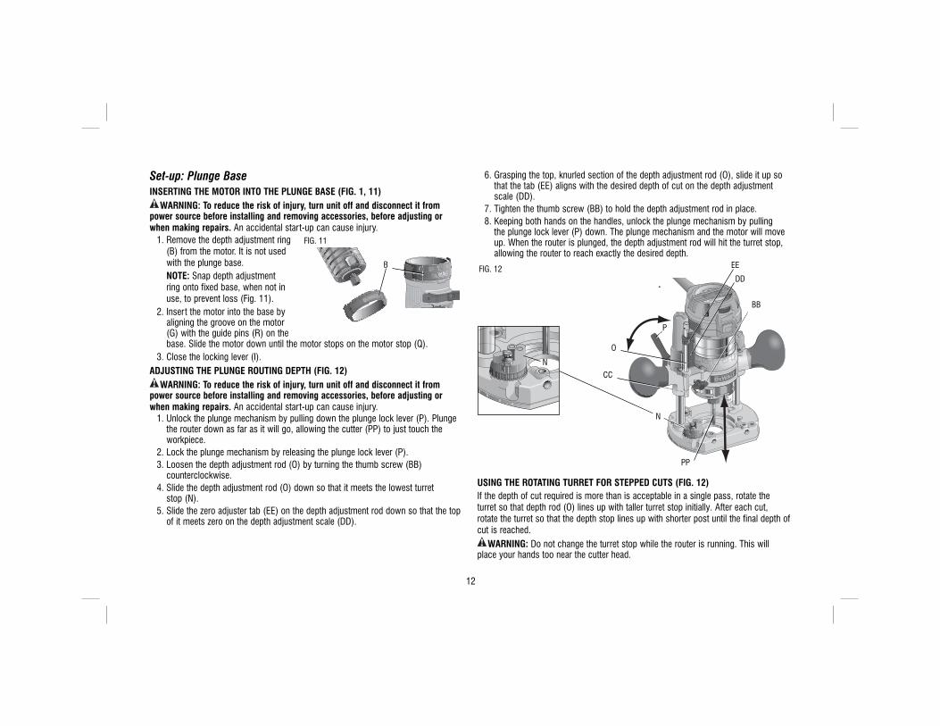
Set-up: Plunge BaseINSERTING THE MOTOR INTO THE PLUNGE BASE (FIG. 1, 11)
WARNING: To reduce the risk of injury, turn unit off and disconnect it from power source before installing and removing accessories, before adjusting or when making repairs. An accidental start-up can cause injury. 1. Remove the depth adjustment ring FIG. 11
B
(B) from the motor. It is not used with the plunge base.
NOTE: Snap depth adjustment ring onto fixed base, when not in use, to prevent loss (Fig. 11).
2. Insert the motor into the base by aligning the groove on the motor (G) with the guide pins (R) on the base. Slide the motor down until the motor stops on the motor stop (Q).
3. Close the locking lever (I).ADJUSTING THE PLUNGE ROUTING DEPTH (FIG. 12)
WARNING: To reduce the risk of injury, turn unit off and disconnect it from power source before installing and removing accessories, before adjusting or when making repairs. An accidental start-up can cause injury. 1. Unlock the plunge mechanism by pulling down the plunge lock lever (P). Plunge
the router down as far as it will go, allowing the cutter (PP) to just touch the workpiece.
2. Lock the plunge mechanism by releasing the plunge lock lever (P). 3. Loosen the depth adjustment rod (O) by turning the thumb screw (BB)
counterclockwise. 4. Slide the depth adjustment rod (O) down so that it meets the lowest turret
stop (N). 5. Slide the zero adjuster tab (EE) on the depth adjustment rod down so that the top
of it meets zero on the depth adjustment scale (DD).
6. Grasping the top, knurled section of the depth adjustment rod (O), slide it up so that the tab (EE) aligns with the desired depth of cut on the depth adjustment scale (DD).
7. Tighten the thumb screw (BB) to hold the depth adjustment rod in place. 8. Keeping both hands on the handles, unlock the plunge mechanism by pulling
the plunge lock lever (P) down. The plunge mechanism and the motor will move up. When the router is plunged, the depth adjustment rod will hit the turret stop, allowing the router to reach exactly the desired depth.
FIG. 12
PP
P
CC
EE
BB
DD
N
O
N
USING THE ROTATING TURRET FOR STEPPED CUTS (FIG. 12)If the depth of cut required is more than is acceptable in a single pass, rotate the turret so that depth rod (O) lines up with taller turret stop initially. After each cut, rotate the turret so that the depth stop lines up with shorter post until the final depth of cut is reached.
WARNING: Do not change the turret stop while the router is running. This will place your hands too near the cutter head.

13
FINE ADJUSTMENT OF ROUTING DEPTH (FIG. 12)WARNING: To reduce the risk of injury, turn unit off and disconnect it from
power source before installing and removing accessories, before adjusting or when making repairs. An accidental start-up can cause injury.The knurled knob (CC) at the bottom end of the depth adjustment rod can be used to make minor adjustments. 1. To decrease the cutting depth, rotate the knob clockwise (looking down from the
top of the router). 2. To increase the cutting depth, rotate the knob counterclockwise (looking down
from the top of the router). NOTE: One complete rotation of the knob results in a change of about 1 mm in depth.CUTTING WITH THE PLUNGE BASE (FIG. 12)
WARNING: To reduce the risk of injury, turn unit off and disconnect it from power source before installing and removing accessories, before adjusting or when making repairs. An accidental start-up can cause injury.NOTE: The depth of cut is locked in the plunge base's default state. The plunge lock requires user actuation to enable the "release to lock" plunge mechanism. 1. Depress the plunge lock lever (P) and plunge the router down until the cutter
reaches the set depth. 2. Release the plunge lock lever (P) when desired depth is reached. NOTE: Releasing the plunge lock lever automatically locks the motor in place. NOTE: If additional resistence is needed use the hand to depress the plunge lock
lever. NOTE: If additional clamping strength is required, press the lock lever further to
tighten in the clockwise direction. 3. Perform the cut. 4. Depressing the plunge lock lever will disable the locking mechanism allowing the
router cutter to disengage from the work piece. 5. Turn the router off.
Operation: All BasesDIRECTION OF FEED (FIG. 13)The direction of feed is very important when routing and can make the difference between a successful job and a ruined project. The figures show the proper direction of feed for some typical cuts. A general rule to follow is to move the router in a counterclockwise direction on an outside cut and a clockwise direction on an inside cut.Shape the outside edge of a piece of stock by following these steps: 1. Shape the end grain, left to right 2. Shape the straight grain side moving left to right 3. Cut the other end grain side 4. Finish the remaining straight grain edge.
1
43
2
FIG. 13
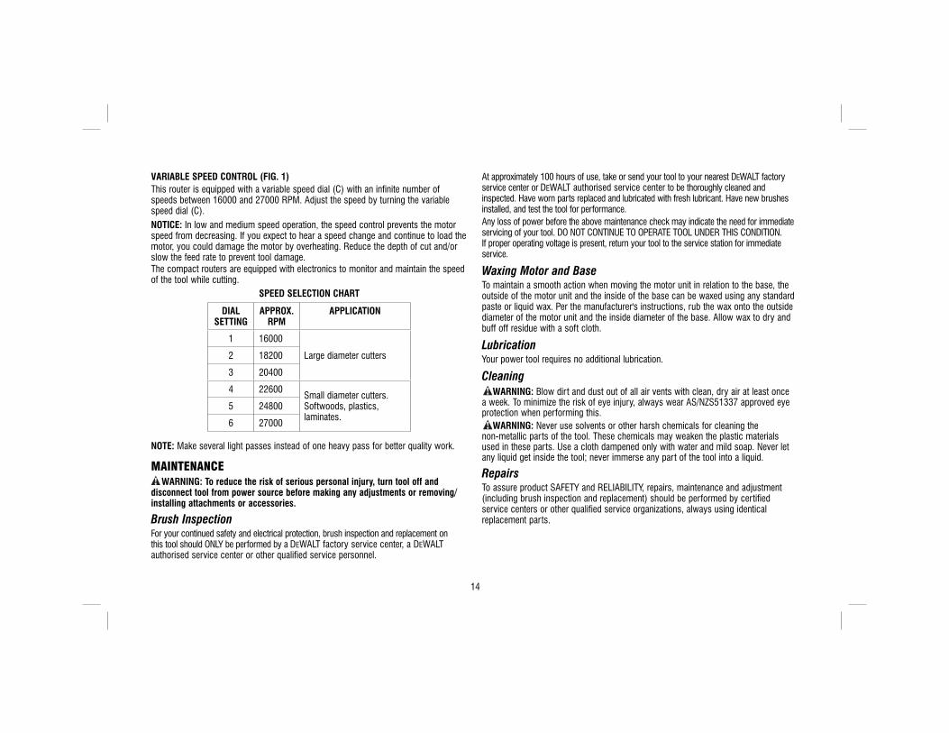
CHOOSING ROUTER SPEED (FIG. 1)Refer to the Speed Selection Chart to choose a router speed. Turn the variable speed dial (C) to control router speed.SOFT START FEATUREThe compact routers are equipped with electronics to provide a soft start feature that minimizes the start up torque of the motor.
14
VARIABLE SPEED CONTROL (FIG. 1)This router is equipped with a variable speed dial (C) with an infinite number of speeds between 16000 and 27000 RPM. Adjust the speed by turning the variable speed dial (C).NOTICE: In low and medium speed operation, the speed control prevents the motor speed from decreasing. If you expect to hear a speed change and continue to load the motor, you could damage the motor by overheating. Reduce the depth of cut and/or slow the feed rate to prevent tool damage.The compact routers are equipped with electronics to monitor and maintain the speed of the tool while cutting.
SPEED SELECTION CHART
DIAL SETTING
APPROX. RPM
APPLICATION
1 16000
Large diameter cutters2 18200
3 20400
4 22600Small diameter cutters. Softwoods, plastics, laminates.
5 24800
6 27000
NOTE: Make several light passes instead of one heavy pass for better quality work.
MAINTENANCEWARNING: To reduce the risk of serious personal injury, turn tool off and
disconnect tool from power source before making any adjustments or removing/installing attachments or accessories.
Brush InspectionFor your continued safety and electrical protection, brush inspection and replacement on this tool should ONLY be performed by a DEWALT factory service center, a DEWALT authorised service center or other qualified service personnel.
At approximately 100 hours of use, take or send your tool to your nearest DEWALT factory service center or DEWALT authorised service center to be thoroughly cleaned and inspected. Have worn parts replaced and lubricated with fresh lubricant. Have new brushes installed, and test the tool for performance.Any loss of power before the above maintenance check may indicate the need for immediate servicing of your tool. DO NOT CONTINUE TO OPERATE TOOL UNDER THIS CONDITION. If proper operating voltage is present, return your tool to the service station for immediate service.
Waxing Motor and BaseTo maintain a smooth action when moving the motor unit in relation to the base, the outside of the motor unit and the inside of the base can be waxed using any standard paste or liquid wax. Per the manufacturer's instructions, rub the wax onto the outside diameter of the motor unit and the inside diameter of the base. Allow wax to dry and buff off residue with a soft cloth.
LubricationYour power tool requires no additional lubrication.
CleaningWARNING: Blow dirt and dust out of all air vents with clean, dry air at least once
a week. To minimize the risk of eye injury, always wear AS/NZS51337 approved eye protection when performing this.
WARNING: Never use solvents or other harsh chemicals for cleaning the non-metallic parts of the tool. These chemicals may weaken the plastic materials used in these parts. Use a cloth dampened only with water and mild soap. Never let any liquid get inside the tool; never immerse any part of the tool into a liquid.
RepairsTo assure product SAFETY and RELIABILITY, repairs, maintenance and adjustment (including brush inspection and replacement) should be performed by certified service centers or other qualified service organizations, always using identical replacement parts.

15
ACCESSORIESWARNING: Since accessories, other than those offered by DEWALT, have not been
tested with this product, use of such accessories with this tool could be hazardous. To reduce the risk of injury, only DEWALT recommended accessories should be used with this product. Recommended accessories for use with your tool are available at extra cost from your local service center. If you need any assistance in locating any accessory, please contact Stanley Black & Decker, 82 Taryn Drive, Epping, VIC 3076 Australia or call 1800 444 224 or (NZ) 0800 339 258.


Stanley Black & Decker82 Taryn Drive, Epping, VIC 3076 Australia • 1800 444 224 (Aust) or 0800 339 258 (NZ)
www.dewalt.com.au • www.dewalt.co.nz
(NOV13) Part No. N377513 D26204-XE Copyright © 2012, 2013 DEWALT
The following are trademarks for one or more DEWALT power tools: the yellow and black color scheme; the “D” shaped air intake grill; the array of pyramids on the handgrip; the kit box configuration; and the array of lozenge-shaped humps on the surface of the tool.


![GB - Triax fibre optic [SAT] 2015 -final](https://img.pdfslide.us/doc/110x75/55c5d673bb61ebfb5d8b4568/gb-triax-fibre-optic-sat-2015-final.jpg)

![GB - Triax Fibre Optic System [2009]](https://img.pdfslide.us/doc/110x75/577d214e1a28ab4e1e94eca8/gb-triax-fibre-optic-system-2009.jpg)