Embed Size (px)
Citation preview
N330
lrc" Air cytinder
NCY2 seiesMagnetically Coupled Rodless Cylinder
Space SavingsBasic or Slider Model Available2 Different Retaining Force OptionsLong Stroke Available (up to 80" - Basic body)Auto Switch Capable

Mounting space reduced by 112Magneticatly coupted Rodtess cytinde, Series NCY2B/NCY2SThe magnetically coupled cylinder is designed to be leak free due to no mechanical con-nection between the piston and the body. The NCY2S slider type offers guided supportideal for light loads when space is limited. The NCY2B basic type is designed to produceforce in applications that require less support.BasicSeries NCY2B
| 6 Bores AvailableI StanAard tube l.D.sI are of,.-ilO.
Great holding powerH type (040) -227.94lbs.L type (040) -140.65 lbs
The max. stroke is 80 inches06-12 in @10-20 in 015-40in@5,Q32,40 -80inLonger stroke available upon request
SliderSlide BearingSeries NCY2S
No external leakageForce is applied through the magneticcoupling of the cylinder piston and guidebody. A rod seal is not required.Intermediate stop positions are easier tomaintain and longer service life can beachieved.
inches (as standard)
lBronze pistons for superior resistancelagainst wear
I Simple fine adjustment of stroke andI addition of auto switch after installation
Two low triction U-cups on piston designed to lowerbreakaway and compensate for seal wear adding tocylinder life
Shock absorber for absorption ofshock and noiseThe SMC shock's original orifice design permits optimalenergy absorption without adjustment within a widerange from high-speed small loads to low-speed largeloads and from small energy to large energy.
Auto switch isattachableAn auto switch can bemounted in any positionalong stroke of cylinder.
2

Magnetically Coupled Rodless Gylindersenes NCY2BBasic Type: ffi ,Q1 0,Q1 5,Q25,Q32,M0
B - Basic type
Bore size
Note: Bolh X t 16 & Xj 60 ootionsavailable on 25 - 40 boresizes only.
How to Order
Stroke/lnches*Magnetic holding power*
OptionsXl 16 - Air hydroX160 - Hish SpeedXB13 - Low Speed
Stroke/Hundreths of an inch*
NCY2BI -l-
Mounting oJ
H - Heavy dutyL - General purpose*See table below
Specifications l MPa=10.1972k9t1cm2
Proof pressure 152psi {10.7kgflcm'?)
Max. operating pressureo6, 10 85psi {5.98kgf/cm'?}
s 15-40 101psi {7.1kgt/cm2}Min. operating pressure 26psi {1.Bkgf/cm'?}Ambient and fluid temperature 14 - 140"F {-10-+60'C}Operating piston speed 2 - 16 inlsec {50-400mm/s}Cushion Urethane cushion at both sidesLubrication Non-lubeStroke tolerance (inch) 0-9.9st:loo3sa, 1 0-39.4st:lfuu, 39.5st-:
positron Horizontal (vertical see page 6)Standard equipment
Bore size I Bore size
1143/85/8'I
1 1/4
Standard StrokeBoresrze
MAX, T(inc
2,3,4,5,6,8,102,3,4,5,6,8,10
1 220
5,1 0 ,15 ,20 ,25 ,30 405,1 0, 1 5,20,25,30,40
805,10,15,20,25,30,405,10 ,15 ,20 ,25 ,30 ,40
(Consult SMC when desired stroke exceeds the max.)
Magnetic Holding Power (lbs. force)

Serres NCY2BCylinder Theoretical Output
Q6, QlO 1N = .2248 lbs 015,025, Q32, Q4O1200
^11004tw$ sooI aooI zoo; 600t soop m3 sooE zoo
100
0 0.1 0.2 0.3 0.4 0.5 0.6 0.7 0.8 0.9 1.0
zo)=
oc(!
10090807060CU
4030201 0
0 0.1 0.2 0.3 0.4 0.5 0.6 0.7 0.8 0.9 1.0
Main Parts
Calculation method/Examole: NCY2B32H-2000Basic weight 2.95 lbs'lAdditionaiweight " O.ozgli lncn |
2'95+(0 079x20)=4 53
Cyl inder st roki . . . . . . . . . . . . . . . . . . . . . zO I
O Since the external moving element revolves incase of the basic type (NCY2B), connect it toanother shaft (LM guide, etc.) or use the slidertype (NCY2S).O When the magnet coupling has been detachedby an external force greater than the magneticholding power, return the external movingelement to the appropriate position by pushing itat the stroke end with a hand (or pushing thepiston moving element with compressed air)0 Careful aligning is required in the connectionto the external load. The longer the stroke is, themore the axis center changes Deliberate beforeuse on how to connecl so as to absorb thedisplacement as described on the right (See theseparate instruction manual for how to connect.)O The allowable load (reference value) in case ofa vertical operation is shown in How to Select onP 6. Consult SMC before purchase withinformation about the operational details(pressure, load, speed, stroke frequency, etc.).O Consult SMC regarding application where thecylinder (surface of cylinder tube/guide shaft)may be exposed to water (hot wate0 or coolingl iouid.
O Flush piping thoroughly before connection inorder to prevent dust or chips lrom enteringthe cylinder.@ Take care not to mark the oulside surface ofthe cylinder tube. This may damage the wear ringand scraper, resulting in malfunctioning of thecylinder
Move the load applying both sidesof the external moving element toit, while absorbing the difference indellection between the guide rodand rodless cvlinder axises
In case o{ high speed andfrequency with large load, install amounting bed on the externalmoving element and connect it tothe bracket.
Avoid wear byhardening thecontact surface.
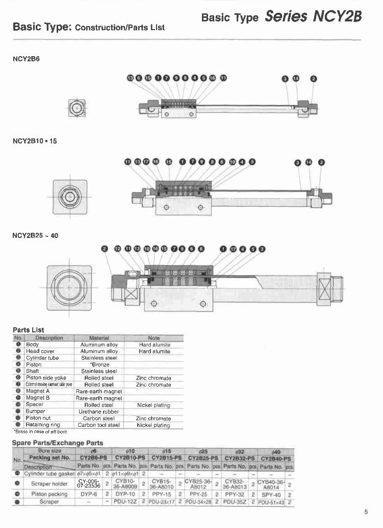
Basic rype Seres NCY2BBaSiC Type: Construction/Parts List
NCY2B6
N C Y 2 B l 0 . 1 5
NCY2B25 - 40
Parts List
tJoay Aluminum al loy Hard aluHead cover Aluminum al lov Hard alumiteCvlinder tube Stainless steelPiston *BronzeShaft Stainless steel
@ Piston side yoke Rolled steel Zinc chromateExlelnal ll]ovino elemenl side voke Rolled steel Zinc chromateMaonet A Rare-earth maonet
o Magnet B Rare-earth maqnetSpacer Rolled steel NickelBumper Urethane rubberPiston nut Carbon steel Zinc chromateRetaininq r ing Carbon tool steel Nickel plat in
cY-006-07-23536
*Brass in case of 06 bore

Serres NCY2BBasic Tvpe: Dimensions
NCY286.10.15
NCY2825.32.40
3B
Mounting nut
Standard for basic type only (2pcs )

Basic rype SerleS NCY2B
How to Select
<How to select applicable type>
1 First, determine the force Fo (N)
I required to move the load horizon-
I tally.t
2 Find the moment arm Lo (cm), the
I perpendicular distance from theI cylinder axis to the point of appli-t '
I cation of force Fo.Y3 Refer to Data 1 . with the calculated
Fo and Lo , the appropriate type,magnetic holding power (L, H type)and bore size and can be selected.
<Data 1: Distance from cylinder axis - Recommended driving force>
ExampleThe required load, Fo =100(N) and themoment arm, Lo = 8cm refering toData 1, draw a vertical line from the8cm value of the horizontal axis. Fromthe intersection of this line with thecuryes labelled H, or, L, a horizontall ine should be drawn passing throughvertical axis to obtain the maximumallowable load force Fo. For this ex-ample, the applicable types corre-sponding to a load force Fo of 100 (N)are NCY2B32H and NCY2B40H,NCY2B4OL.
1N = 145 lbs.1 cm = 0.3937 inches
zl!
ooooc
Epo
ooEEoo
E
4003002001005068201 05
0 1 2 3 4 5 6 7 8 I 101112131415Distance from cylinder axis: Lo (cm)
z.Loeoo
o
oEEooo
403020
1 0
5
11 2 3 4 5 6
Distance from cylinder axis: Lo (cm)
010
Fo
z.
ro=oc
EooEcoEEooo
CE
20
1 0
c
11 2 3 4 5 6 7 8 9
Distance from cylinder axis; Lo (cm)
2 300;200rid 1OO
"E soq, 40
8 2 88 1 0o
E sEaE, 1
o 1 2 3 4 5 6 7 I 9 1 0 1 1 1 2 1 3 1 4 1 5Distance trom cylinder axis: Lo (cm)
?: 5 0Fr 405 3 0F z oE r oooE 5oEEoo
c E 16 7 A I 1 0 1 1
Distance from cylinder axis: Lo (cm)
^ 300=200a 100oP 5 0.rr 40P 3 0'= 20= 1 0o
5 cEE
e 14 5 6 7 8 9 1 0 1 1 1 2 1 3
Distance from cylinder axis: Lo (cm)

Serres NCY2B
Inner tube deflections Weight limitations of mounting hardware Intermediate position stopThe inner tube wil l deflect due to theweight of the actuator. The amount ofdeflection increases with cylinder strokelength. Load
_] Clearance(0 2-0.5mm)
'Clearance C between the guide and cylinder should beselecled on the basrs of distance trom lhe tube center andinner tube dellection Standard clearance: (Tubedeflection) +1 5-2mm
The NCY2B series does not allow directmounting of the load. The load must beguided by other means (LM guide etc.). Themounting hardware and the load, shouldbe designed to meet the following weightl imits.Weight
l f lhe weight ot your mounting hardware exceeds theabove limits, please contact an SMC representative
Vertical operationThe load should be guided by a ball typebearing (LM guide etc.). lf a slide bearingis used, the loading configuration leads tohigh frictional values between the sealsurfaces, resulting in reduced cylinderperformance.
When stopping the load at an intermedi-ate position, please use the operatingpressures given in the list below.
1N=.2248 lbs
Iwork I
1Kg=2.2 lbs1 MPa=1 45
'The above data is with cylinder body in mid-strokeposition
Note) Piston can be uncoupled i l pressure exceeds the range
4 0 8 0 1 2 o 1 6 0 m

Magnetically Coupled Rodless Cylindersenbs NCY2SSl ide Beari ng Typ e= ffi ,Q1 0,Q1 5,Q25,Q32,M0
Bore size
Magnetic holdingH - Heavy dutyL - General Duroose*See
table on page 8
To Order NCDY2SSwitch RailSeparately
Bore Part No.*6 RCY6-O1 0 RCY10-O1 5 RCY15-O25 RCY25-O32 RCY32-O40 RCY40-O
*O = specify stroke
Stroke /Inch*
Stroke/Hundreths of an inch*.Note: Stroke length must be indicated as 4
digits First and second digit: Stroke/Inch, Third and Fourth digit: Stroke/Hundreths oI an inchExample: 0525 = 5 25 (5 1/4) Inch stroke
Stroke Adjustment
How to Order
_ - Adjustment bolts (Std) see pg 1 1B - With shock absorbersBS - With one shock absorberBC - With cap type shock absorberBCS - With one cap type shock absorber
OptionsXl16- Air HydroXl6t- High SpeedXBl3- Low Speed
Number of switches
Applicable auto switchauto switch
'"L" is added to the end when the lead wire is 3m lonoExample) 473L--. D-A73LHowever, 3m is applied to D-F7NTL and D-F7BAL bystandard(Please consult SMC in case of 5m length )
"Consult us when using a two-color display type auto switch (D-F79W)
1 p c
Reed switch
D-A73D-A8OD.A72HD-A73HD-A76HD.A8OHD-A73C
SolidD-F79D-F7PD-J79D-F7NVD-F7PVD-F7BVD-J79CD-F7NTL
D.F7PWD-J79WD.FTBALD-F79F
Reed Switch Solid State SwitchAuto liw mehm
mthd:i ADolication
D-F79 ( N P N ) 5,12,24VDC(4 5-28VDC)
28VDC or less il50mA or tess) lC circuit, Relay,Sequence controllerI wire systen
rPNPI - (100mA or less)D.J79 2aVDC (10-28\lDC) (5-150mA)24VDC Relav,
ouence contrbllerI wire systen
(NPN) 5,12,24VDC(4.5-28VDC)
28VDC or less 11s0mA or tesl lC circuit, Helay,Sequence controller(PNP) (100mA or less)
24VDC {10^28VDC) (5'150mA)wrro sysrem
( P N P ) ;,12,24VDCi4 5-28VDC (80mA or less) circuit, Relay,tence controller
2 wire system 2aVDC {10-28VDC) (s-40mA) Relav.contiollel
wrre syst€r(-) 24VDC (10-28VDC) {5a0mA)24VDC Relay,Sequencecontrol ler
.J79C ) sysler24VDC (10-28VDC) (5-150mA)
LF systen r4vDc (20-26VDC]26VDC or less (40mA or less)}F ,12,24V0C(4 5-28VDC28VDC or less (40mA or les) lC circuit, Helay,
SeoLrence controller(NPN)lo tAv i l l t I 28VDC or less (80mA or less)
'A two-color display type auto switch (D-F79WI is mountable Consult us when usino il
Loadvoltage
Max. load currenland load crtrent
range imAJ.*72H , 200vAc 5 - 1 0 Relay,
Sequencecontroller
24VDC 5-40100vAc 5-204-8VDC 20 lC c i rcu i t
t *"^;; .24V A3or less 50 Relay, lC circuit,
Sequencecontroller
48V38 40100v63 20
24VDC 5-40 R e l a y ,
!c 24V 33or lesr 50 y, tC.: circuit,
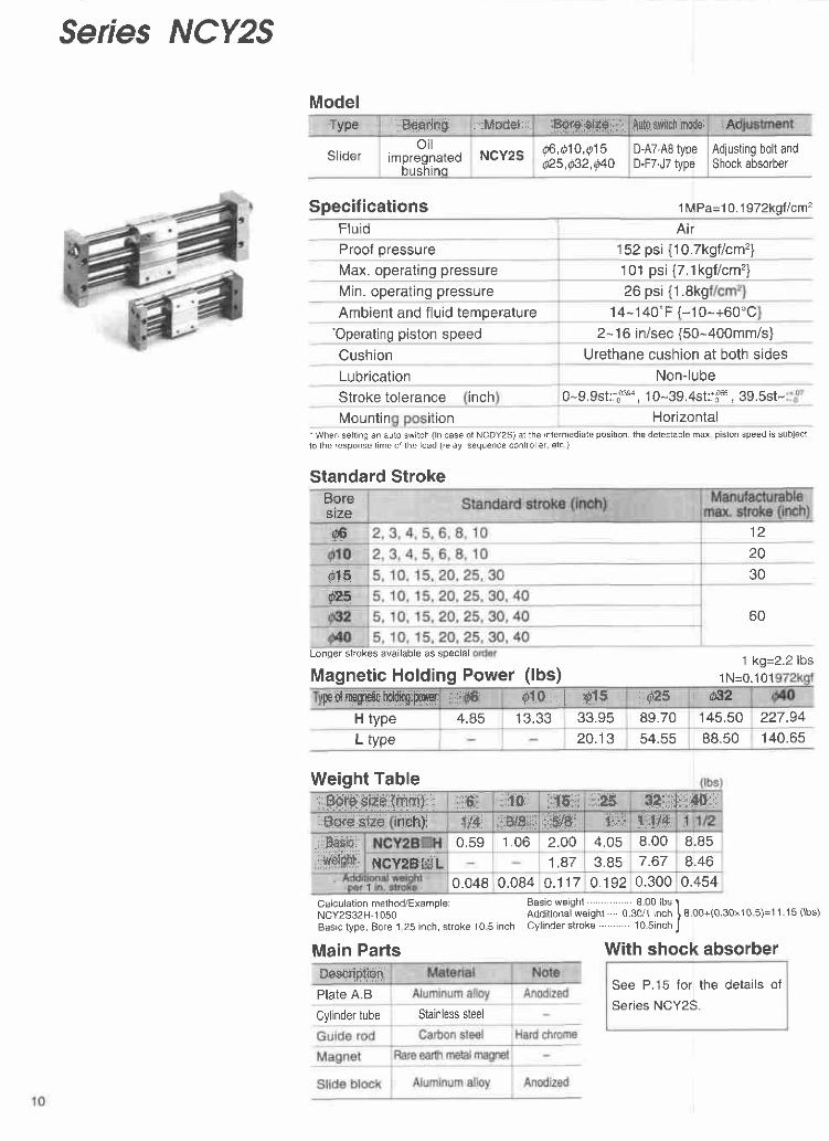
Series NCY2S
Specifications l MPa=10.1972k91/cm2
Flu id
Proof oressure 152 psi{1O.7kgf lcm'?)Max. operating pressure 101 psi{7.1kgf/cm'z}Min. operating pressure 26 ps i {1 .8k9Ambient and f luid temperature 14-140"F {-10-+60'C
'Operating piston speed 2- 1 6 in/sec {50-400mm/s}Cushion Urethane cushion at both sidesLubrication Non-lubeStroke tolerance inch 0-9.9st:1003s, 1 0-39.4st:lfuu, 39.5st-
Mountin Horizontal'When setting an auto switch (in case of NCDY2S) at the inlermediate position, the detectable max piston speed is subjectlo the response time ot the load (relay, sequence controller. etc )
Standard StrokeBoresize06 1 2
20015 300?;5
Longer strokes available as special 1 kg=2.2 lbsMagnetic Holding Power (lbs)
Air
ition
60
Weight Table
Calculation method/Example:NCY2S32H-1 050Basic type, Bore 1 25 inch, stroke 10 5 inch
Main PartsDescription"Plate A.B
Basic weight 8.00 lbs 1Addi t ional weight . . . . 0.30/1 inch ! 8.00+(0.30.10 5)=11.15 ( lbs)Cyl inder st roke . . . . . . . . . . . 10.s inch J
With shock absorber
See P.15 for the deta i ls of
Series NCY2S.
ModelType rFeafins : ' :Modet: i fi'A,lrH H-,&"u;i:rAuto swrtch rmdel Ad
Sl ideroi l
impregnatedbushino
NCY2S @,Q10 ,Q15Q25,Q32,Q4o
D-A7'A8 typeD-F7.J7 type
Adjusting bolt andShock absorber
1N=0 .101pof magneli:hddkqryryr,ffi @10 I i4rtS $ffi F2
H type 4.85 13.33 33.95 89.70 145.50 227.94L type 20.13 54.55 BB.50 140.65
.Boro ohe (rnm) ;if i i i 10 1 5 : r 2s H : . l: : i l0. :Bore size nch) {:i,f 3ls:': '$#i ilii 'l'114I
;.iilE6ic:l:,sxd.ll:
0.59 1 . 0 6 2.O0 4.05 8.00 8.85NCYzEffiL 1 . 8 7 3.85 7.67 8.46
1 0.0480.084 o .1170.1920.3000.454
Cylinder tube Stainless steel

Sfider Type /Slide Bearins SefieS NCY2SConstruction/Pafts ListNCDY2S25H
Parts List
External movingelement side tube
Parts List
tBrass in case ol s6 bore
Chrome-Molvbden steel
Daohne Coronex Grease No.1
Mobilux Grease No.1
Sunlight Grease No.2Sunlight Grease EM1Sunlight Grease EP1Sunlight Grease EP2Dynamic Grease MP1Dynamic Grease MP2
Alvania Grease No.1Alvania Grease No.2Alvania EP Grease No.1Alvania EP Grease No.2
Kosmo Grease Dynamax No.1Kosmo Grease Dvnamax No.2
Mult inoc Grease No.1Multinoc Grease No.2Epnoc Grease No.1Eonoc Grease No.2Gemico Grease MP-1Gemico Grease MP-2Gemico Grease MH-1Gemico Grease MH-2
Note 1 ) The gresss name No. shows the consistency. . t 1
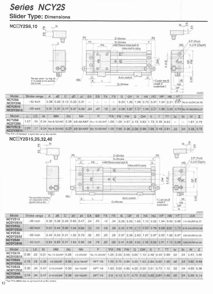
Serres NCY2SSlider Type: Dimensions
NCEY2S6,1O N
*The PA's dimension is symmetrical at the center
NCmY2Sl 5,25,32,40dlI
(DU
q tY]
L 'J.coulgtlqq4q4-Depth olcounter bore C
Q+Stroke
I:+
I="l
Q+Stroke&c!u-!!!!!qq4q4-Depth olcounler bore C
The auto switch mounting railis mounlable on the opposite
Strol A E (l tfr EA iB t-A FB G G P H t{A t-{G FJP rs H
2S6- 1 2 i n c h 0.28o.260 1 30.300.31 0.20 1 . 2 6 1 . 0 60.75 0.31 1 . 0 2 0 . 3 1 ddtNo 8-32UNCx0 26
-20 inch 0.310.31 o.174 4 7 0.39 .24 .47 12 t ,?0 : 0.26 i"ig,? .tA-f 1.00.0iSl ;L,Sffi 0;,?{ 10-32UNFx0.37
rdel ; tu ' LU M MM (N) N N P -PA PB PW QW S : T TT ia tb l/v zNCY2S6 1 . 5 7 . 1 4 0.24 No 8-32UNC0.35 3/8-32UNEFNo .10 -32UNf1 . 0 01 0 0 1 . 9 7 2 1 3 0.63 t . / J 0.39 0 6 3 '1 .81 2.75
ilCVsSl0i lenVtStn 1r?? . { f 0.24No.8-32UNC0"37 1.00$m 2.96 eifl.su.t'5 :f .s60.49 0.81 st 228 1 6
rail is mounlable on the
Stroke ranoe A D tu EA Ets FA tts G GP t-,1 HA HC : [.,i HS n J>NCY2S15 -30 inch 0.32 0.38 0 2 0 0.65 0.47 .24 5 1 , t z .24 o.262.05 1 6 3 1 . 1 40.56 1 . 5 40.59 0.88 1 /4-28UNFxo.37
iY2S25ifrvrctE 0,ar 0;44 0;a6 0;6s i$*, ;55 1 6 .26 0 3 3 z , r o 2,::f8':ti{til 0_79 2.09 0igt 0:*g
NCY2S32NCDY2532
-60 inch 0.45 0.550.31 1 .320 7 9 .32 O J 20 28 0.37 3 3 9 z .o \ t 1 . 9 70.97 2.52 1 . 0 60.97
-60 inch 0.51o.550.31 1.64 0.98 .3S . t Y -4lJ ;Eg 0.41 4;0s$;00 2.05 0,99 2,91 1 . 1 8
NCY2S15
NCY2S32NCDY2S32
z2.83 I 3 86
4 4 9
5.36
12'The PA's dimension is symmetrical at the center
6 . 1 4

#ties,NCY25Slider Type
Application InformationO Horizontal operation (Mounted on floor) @ lnclined operation (Operational direction)
Max. l ive load (Center of slideoie get @ 0r0 015 Q25 s8s @40
1 . 8 3.0 7.O 20.0 30.0 5012 i n . 20 in . 30 in. 60 in. 60 in . 60 in .
Basic design value: Those of the max allowable load are 60% of the max thrust (P=0 TMPa)However, the above load is subject to the stroke length in case of everycylinder size due to the l imit for deflection ol the guide shatt (Be carefulof coelficient d ) ln case of some operational direction, the allowable loadmay be different from the basic design value
@ Horizontal operation (Mounted to wall)
lo: Distance from mounting surface to load'scenter ol gravity (cm)
@ Vertical movement
lo: Distance from mounting surface to load's center ofgravily (cm)- Note) Principally, it becomes impossible to operate(Reference value)Note) A salety coefticient for avoiding fall is taken intoconsideration
Angle coell icient [k]: k=[-45"(=e)]=-[-60']=0 9, [-75"]=0 8,[-e0']=0 7
lo: Distance from mounting surtace to load'scenter ol gravity (cm)
@ Inclined operation (Vertical to operational direction)
lo: Distance from mounling surface to load'scenter of gravity (cm)
@ The load's center ol gravity is otfset in the operational direction, (l)
lo: Distance from mounting surface to centerof sftde block (cm)
3cos0+2(1.9+lo)sin0o ' 1 0 . 5 ' K
a.5.447+2lo
a ' 1 2 . O8.4+2locr '36.4
10.6+2 loa . 1 4 0
13.8+2loa.25817+2loo.520
20.6+2lo

Serres NCY2S
O Horizontal operation (Load pressing, Pressure) How to calculate cr when selecting allowable loada should be considered to be a coeff icient decided in accordancewith each stroke because the max. allowable load is related to thecyl inder stroke and varies as shown in the table below.
Ex.) In case ol NCY2S25il-2560:(1) Max. al lowable load=20k9(ziVgl,al lowable load in caie ol (650)st=13.6kg 1s; o=1!S=o.oa
(25.6inch-25.4=650mm)
Catcutation formula for cx (cr<1) lfigi'3'i3ifl')
F: Drive (Position, lo from slide block) drag (kg)lo: Distance from mounting surface to load'scenter ol gravity (cm)
@ Horizontal operation [Load,Otfset in operational direction (l)]
to: Distance from center of slide block toload's center of gravity (cm)
Model NCY2S25 NCY2332 NCY2S40
C[= 1 6(t se-t 3x10 3xST)
201 g(2 26-1 3x1oixsT)
30lgQ
tl-t 3x1 0-3xST)
50Note) Apply o=1 in case of: 010-300mmST, 015-500mmST, 025-500mmST, 032 0-600mmST,
and d40-600mmsT at the max
OAvoid applying a load to the cylinder exceedingthe caluculation value in the data for selection@Secure the cylinder nol to the slide block but tothe plate.@Consult us for operation under an ambiencewhere the cylinder (sudace of cylinder tube/guideshatt) may be exposed to water (hot water) orcool ing l iquidG)Periodically grease the bearing of the slide block(See the applicable greases described on P 9 )OConsul t our sales dept for the change of themagnet holding power (ex NCY2S25L-NCY2S25H), which should be changed in ourDlanlOAvoid diassemble the magnet 's component (p is-ton moving element or external moving element) ,which may cause holding powels deterioration ordefectOPrincipally, avoid operation in a vertical direc-tion. lf it cannot be avoided, consull us.
1 O(0 86-1 3.10-r .Sr)

sf iderrype Seres NCY2S
See the "shock absorber" in the catalog (CAT. N371) for details.
' l t is the max absorption energy/hour per 1 cycle Therefore,the operating frequency can be increased according to the absorption energy
With shock absorber/Dimensions
NCYzSrS
absorber model NRB(C)37-025 NRB(C)50-030NRB(C)s6-045NRB(C)75-04s25(0.3) 50(0.6) 170(2) 17O(2)
in (ffim) 0.25(6) 0.30(7) 0 .45 (12 ) 0.45(12)
fVs{nr/s) 16(5 )
iF.requoncy cycle/rnin
ffi80 70 45
1 4-1 76(-1 0-80)45
Extended 0.77(0.35) 1.43(0.65) 1.54(0.70) 1.54(0.70)
Compressed 1.6s(0 .75) 2 .12(0 .e6) 3 .5e(1 .63) 3 .59 (1 .63 )
Veight 0.04(20) 0.08(35) 0 .13 (60 ) 0.26(120)
. NBI - r '
241 923
30
33494847
Hin
I1
,NOi'@
NRB37-025
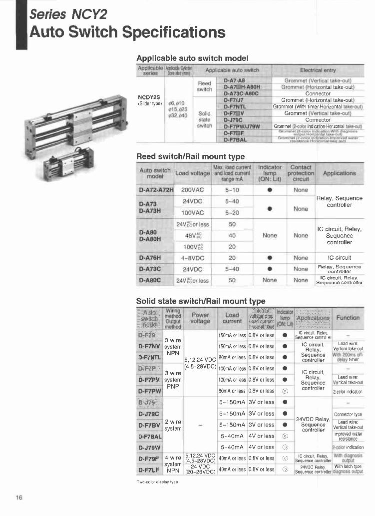
Serres NCY2Auto Switch Specifications
NCDY2S(Slider type)
tal take-oulConnector
Grommet (Horizontal take-outGrommet (With timer.Horizontal
GrommetConnector
Grommet indication.Horizontal
Relay, Sequencecontroller
lC circuit, Relay,Sequencecontroller
lC circuitRelay, Sequence
controllerlC c i rcui t , Relay,
Seouence contro l ler
Applicable auto switch model
Reed switch/Rail mount type
Solid state switch/Rail mount type.: uto::::swlm;:'fie$ell
: . llltattt$i:..$,,s,1tffi#,r.*PLoafl csrmnt[r.std.nl1BrilA
. i i l r i a ; i : ,! r l i L . r r t , "
FNP.Fffi-I r r l l r r ' l ! ! i . i i e i ' , !
n-r'zg.3 wiresystemNPN
5,12,24 VDC(4.5-28VDC)
150mA or less0.8V or less o lC circuit, Relay,iequence controlle
D.F7NV 150mA or less0.8V or less O lC circuit ,Relay,
Sequencecontrol ler
Lead wire:Vertical take-out
D'F7NTL 80mA or less0.8V or less o t imer
llrFfH ,:3 wiresystemPNP
100mA or less0,8V or less olC circuit ,
Relay,Sequencecontrol ler
b;Frrv 100mA or less0.8V or less o Lead wire:rtical take-out
80mA or less0.8V or less @ 2-color indication
D--t?9 ..
2 wiresystem
5-150mA3V or less o
24VDC Relay,Sequencecontrol ler
D-JT9C 5-150mA3V or less o Connector type
D.F7BV 5-150mA3V or less a Lead wire:Vertical take-oul
D.FTBAL 5-40mA 4V or less @ lmproved waterresrstance
D-J79W 5-40mA 4V or less @ indication
D-F79F 4 wiresystemNPN
5,12,24 VDC(4.5-28VDC)40mA or less0.8V or less @ lC circuit, Relay,
leouence controllel
D-F7LF24 VDC
(20-26VDC)40mA or less0.8V or less @ 24VDC Relay,ieouence controller
Wilh latch type
Two-color display type
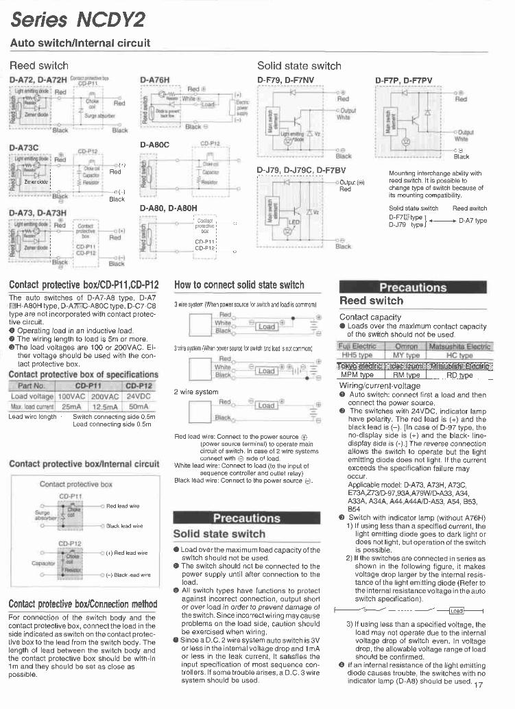
Serres NCDY2Auto switch/lnternal circuit
Reed switch Solid state switchD-F79. D-F7NV
D-J79, D-J79C, D.F7BV
D-F7P D.F7PV
Mounting interchange ability withreed switch lt is oossible tochange type of switch because ofits mounting compatibility.
Solid state switch Reed switch
R |#Yf ] .-..-.-- D-A7 typeu-J lv rypeJ
Contact capacityO Loads over the maximum contact capacity
of the switch should not be used.
O Auto switch: connect first a load and thenconnect the power source.
O The switches with 24VDC, indicator lamphave polarity. The red lead is (+) and theblack lead is (-). In case of D-97 type, theno-display side is (+) and the black- l ine-display side is (-).1 The reverse connectionallows the switch to operate but the lightemitt ing diode does not l ight. l f the currentexceeds the specification failure mayoccur.Applicable model: D-A73, A73H, A73C,E7 3 A,n 3D-97,93A,A79WD-A33, A34,A33A, A34A, A44,A44ND-A53, A54, 853,B54
@ Switch with indicator lamp (without A76H)1) l f using less than a specif ied current, the
l ight emitt ing diode goes to dark l ight ordoes not light, but operation of the switchis oossible.
2) lf the switches are connected in series asshown in the fol lowing f igure, i t makesvoltage drop larger by the internal resis-tance of the l ight emitt ing diode (Refer tothe internal resistance voltage in the autoswitch specif ication).
-*J- -___w
3) l f using less than a specif ied voltage, theload may not operate due to the internalvoltage drop of switch even. In voltagedrop, the allowable voltage range ot loadshould be confirmec.
@ lf an internal resistance of the lightemittingdiode causes trouble, the switches with noindicator lamp (D-A8) should be used. 17
D-A80C
D.A8O. D.A8OH
o OBlack
(+ lRed
Z6ner dbde Output (o)Red<( - )
Black
i Cmlacl lI protectrve ;.............-'i 00x
ico-pr r' cD-P12
How to connect solid state switchContact protective box/CD-Pl 1,CD-PI2The auto switches of D-A7.A8 type, D-A7ffi H.A80H type, D-Affi 'A80Ctype, D-C7.CBtype are not incorporated with contact protec-tive circuit.O Operating load in an inductive load.O The wir ing length to load is 5m or more.@The load voltages are 100 or 200VAC. Ei-
ther voltage should be used with the con-tact protective box.
Contact protective box/Connection methodFor connection of the switch body and thecontact orotective box. connect the load in theside indicated as switch on the contact protec-tive box to the lead from the switch body. Thelength of lead between the switch body andthe contact protective box should be with-in1m and they should be set as close asoossible.
3 wire system (When power source for switch and load is commom)
3 wire syslem (When power source for switch and load is nol commom)
MPM tvpe I RM rvpe I RD tvpeWi ring/current.volta ge
2 wire system
Red lead wire: Connect to the power source @(power source terminal) lo operate maincircuit of switch. In case of 2 wire systemsconnect with O side of load
White lead wire: Connect to load (to the input ofsequence controller and outlet relay)
Black lead wire: Connect to the power source O.
O Load overthe maximum load capacityof theswitch should not be used.
g The switch should not be connected to thepower supply until after connection to theload.
@ All switch types have functions to protectagainst incorrect connection, output shortot over load in order to prevent damage ofthe switch. Since incorrectwir ing maycauseproblems on the load side, caution shouldbe exercised when wir ing.
@ Since a D.C.2 wire system auto switch is 3Vor less in the internal voltage drop and 1mAor less in the leak current, i t sat isf ies theinput specification of most sequence con-trol lers. l f some trouble arises, a D.C. 3 wiresystem should be used.
Reed switch
Lead wire length-Switch connecting side 0 5mLoad connecting side 0 5m
Red lead wire
Black lead wire
(+) Red lead wire
(-) Black lead wire

Serrbs NCY2Specifications for made to order modelsContact SMC for the details of dimensions, specifications, and date of delivery.
Nc(D)Y2sffiWxror <Basic type>
norF..ffilW",* N.Y2Blffilffi*tt.<Slider type>
High speed drive with a piston speed of 1500mm/s (basic type) ispossible. (When without load)
Specifications
Note 1 ) When operating lhis cylinder at high speed, be sure to provide a shock absorberNote 2) The standard type of CYIS and CYlL can produce max piston speed ol 1000mm/sNote 3) Bores 6 - 15 (basic type) are fully ported and do not require the x'l60 option
rucvzsFiffil
Specifications
Basic 2 - 60 in/s (50 - 15000mm/s)Slider 2 - 40 in/s (50 - 1000mm/s)
<Basic type>
NcY2BE-]ffi*tt.<Slider type>
NcY2sffiffilffilfiW#x"e
Specifications
Note) Piping is from each plate on both sides
Dimensions


![Secia Seies [Special Series] Haas TL Series](https://img.pdfslide.us/doc/110x75/6264ce71f8fc7656f651ee03/secia-seies-special-series-haas-tl-series.jpg)