Embed Size (px)
Citation preview

1/10
Technical data sheet: S000092411EN-1 Updated: Created: 02/06/2016
Cat. No(s): 0 674 64 - 7 521 47 - 7 527 47KNX temperature control panel
CONTENT PagE
1. Use . . . . . . . . . . . . . . . . . . . . . . . . . . . . . . . . . . . . . . . . . . . . . . . . . . . . . . . . . . . . . . . . . . . . . . . . . . . . . . . . . . . . . . . . . . . . . . . . . . . . . . . . . . . . . . . . . . . . . . . . . . . . . 2
2. Description. . . . . . . . . . . . . . . . . . . . . . . . . . . . . . . . . . . . . . . . . . . . . . . . . . . . . . . . . . . . . . . . . . . . . . . . . . . . . . . . . . . . . . . . . . . . . . . . . . . . . . . . . . . . . . . . . . . . . . 2
3. Technical characteristics . . . . . . . . . . . . . . . . . . . . . . . . . . . . . . . . . . . . . . . . . . . . . . . . . . . . . . . . . . . . . . . . . . . . . . . . . . . . . . . . . . . . . . . . . . . . . . . . . . . . . . . . . 23.1 Electrical characteristics . . . . . . . . . . . . . . . . . . . . . . . . . . . . . . . . . . . . . . . . . . . . . . . . . . . . . . . . . . . . . . . . . . . . . . . . . . . . . . . . . . . . . . . . . . . . . . . . . . . . . . . . . . . . . . . . . . . . . 23.2 Climate characteristics . . . . . . . . . . . . . . . . . . . . . . . . . . . . . . . . . . . . . . . . . . . . . . . . . . . . . . . . . . . . . . . . . . . . . . . . . . . . . . . . . . . . . . . . . . . . . . . . . . . . . . . . . . . . . . . . . . . . . . 23.3 Mechanical characteristics . . . . . . . . . . . . . . . . . . . . . . . . . . . . . . . . . . . . . . . . . . . . . . . . . . . . . . . . . . . . . . . . . . . . . . . . . . . . . . . . . . . . . . . . . . . . . . . . . . . . . . . . . . . . . . . . . . 2
4. Dimensions . . . . . . . . . . . . . . . . . . . . . . . . . . . . . . . . . . . . . . . . . . . . . . . . . . . . . . . . . . . . . . . . . . . . . . . . . . . . . . . . . . . . . . . . . . . . . . . . . . . . . . . . . . . . . . . . . . . . . 2
5. Connection . . . . . . . . . . . . . . . . . . . . . . . . . . . . . . . . . . . . . . . . . . . . . . . . . . . . . . . . . . . . . . . . . . . . . . . . . . . . . . . . . . . . . . . . . . . . . . . . . . . . . . . . . . . . . . . . . . . . . . 3
6. Installation . . . . . . . . . . . . . . . . . . . . . . . . . . . . . . . . . . . . . . . . . . . . . . . . . . . . . . . . . . . . . . . . . . . . . . . . . . . . . . . . . . . . . . . . . . . . . . . . . . . . . . . . . . . . . . . . . . . . . . 36.1 Physical installation . . . . . . . . . . . . . . . . . . . . . . . . . . . . . . . . . . . . . . . . . . . . . . . . . . . . . . . . . . . . . . . . . . . . . . . . . . . . . . . . . . . . . . . . . . . . . . . . . . . . . . . . . . . . . . . . . . . . . . . . . 36.2 System installation . . . . . . . . . . . . . . . . . . . . . . . . . . . . . . . . . . . . . . . . . . . . . . . . . . . . . . . . . . . . . . . . . . . . . . . . . . . . . . . . . . . . . . . . . . . . . . . . . . . . . . . . . . . . . . . . . . . . . . . . . . 3
7. Operating modes . . . . . . . . . . . . . . . . . . . . . . . . . . . . . . . . . . . . . . . . . . . . . . . . . . . . . . . . . . . . . . . . . . . . . . . . . . . . . . . . . . . . . . . . . . . . . . . . . . . . . . . . . . . . . . . . 3
8. System applications . . . . . . . . . . . . . . . . . . . . . . . . . . . . . . . . . . . . . . . . . . . . . . . . . . . . . . . . . . . . . . . . . . . . . . . . . . . . . . . . . . . . . . . . . . . . . . . . . . . . . . . . . . . . . 38.1 Heating application . . . . . . . . . . . . . . . . . . . . . . . . . . . . . . . . . . . . . . . . . . . . . . . . . . . . . . . . . . . . . . . . . . . . . . . . . . . . . . . . . . . . . . . . . . . . . . . . . . . . . . . . . . . . . . . . . . . . . . . . . 38.2 Cooling application . . . . . . . . . . . . . . . . . . . . . . . . . . . . . . . . . . . . . . . . . . . . . . . . . . . . . . . . . . . . . . . . . . . . . . . . . . . . . . . . . . . . . . . . . . . . . . . . . . . . . . . . . . . . . . . . . . . . . . . . . 38.3 Heating and Cooling application . . . . . . . . . . . . . . . . . . . . . . . . . . . . . . . . . . . . . . . . . . . . . . . . . . . . . . . . . . . . . . . . . . . . . . . . . . . . . . . . . . . . . . . . . . . . . . . . . . . . . . . . . . . . 3
9. Settings . . . . . . . . . . . . . . . . . . . . . . . . . . . . . . . . . . . . . . . . . . . . . . . . . . . . . . . . . . . . . . . . . . . . . . . . . . . . . . . . . . . . . . . . . . . . . . . . . . . . . . . . . . . . . . . . . . . . . . . . . 49.1 Display during installation . . . . . . . . . . . . . . . . . . . . . . . . . . . . . . . . . . . . . . . . . . . . . . . . . . . . . . . . . . . . . . . . . . . . . . . . . . . . . . . . . . . . . . . . . . . . . . . . . . . . . . . . . . . . . . . . . . 49.2 Display during use . . . . . . . . . . . . . . . . . . . . . . . . . . . . . . . . . . . . . . . . . . . . . . . . . . . . . . . . . . . . . . . . . . . . . . . . . . . . . . . . . . . . . . . . . . . . . . . . . . . . . . . . . . . . . . . . . . . . . . . . . . 4
10. Standards and approvals. . . . . . . . . . . . . . . . . . . . . . . . . . . . . . . . . . . . . . . . . . . . . . . . . . . . . . . . . . . . . . . . . . . . . . . . . . . . . . . . . . . . . . . . . . . . . . . . . . . . . . . . 5
11. Maintenance . . . . . . . . . . . . . . . . . . . . . . . . . . . . . . . . . . . . . . . . . . . . . . . . . . . . . . . . . . . . . . . . . . . . . . . . . . . . . . . . . . . . . . . . . . . . . . . . . . . . . . . . . . . . . . . . . . . 5
12. Communication objects . . . . . . . . . . . . . . . . . . . . . . . . . . . . . . . . . . . . . . . . . . . . . . . . . . . . . . . . . . . . . . . . . . . . . . . . . . . . . . . . . . . . . . . . . . . . . . . . . . . . . . . . . 612.1 List of objects. . . . . . . . . . . . . . . . . . . . . . . . . . . . . . . . . . . . . . . . . . . . . . . . . . . . . . . . . . . . . . . . . . . . . . . . . . . . . . . . . . . . . . . . . . . . . . . . . . . . . . . . . . . . . . . . . . . . . . . . . . . . . . 612.2 ETS parameters . . . . . . . . . . . . . . . . . . . . . . . . . . . . . . . . . . . . . . . . . . . . . . . . . . . . . . . . . . . . . . . . . . . . . . . . . . . . . . . . . . . . . . . . . . . . . . . . . . . . . . . . . . . . . . . . . . . . . . . . . . . . 9

2/10CONTENTS
Technical data sheet: S000092411EN-1 Updated: Created: 02/06/2016
Cat. No(s): 0 674 64 - 7 521 47 - 7 527 47KNX temperature control panel
1. USE
Combined with a KNX room temperature controller (with an embedded temperature control algorithm), the KNX temperature control panel is used to manage the heating/cooling control system (fan coil control unit, heating/cooling valve, electrical load, etc) in the rooms where it is installed, and can be configured for different applications as required. The temperature control panel incorporates a user interface and a temperature sensor.
This device is completely configurable in term of parameters, operating modes and other features. Depending on the type of use, the backlit display will show the following information: the current function or mode (Heating, Cooling; Comfort, Eco, Frost/Overheat Protection), the measured room temperature, the defined temperature setpoint, the fan coil speed. It is a native KNX device and all the configurations and associations must be made via ETS software (ETS versions 3, 4 and 5) only.
2. DESCrIPTION
1 2 3 4 5
6
MODE
FAN
7
8
9
13 12 11 10
14
15
+
-
1 - Heating mode.
2 - Cooling mode.
3 - Comfort mode.
4 - Eco mode.
5 - Frost/Overheat protection.
6 - MODE key: A short press changes the device operating mode; a long press changes the function.
7 - + key: increases the set value.
8 - - key: decreases the set value.
9 - FaN key: sets the fan-coil speed to one of 3 levels + automatic.
10 - Heating On indicator.
11 - Cooling On indicator.
12 - Fan coil speed indicator, 3 levels.
13 - Fan coil in automatic mode indicator.
14 - Measured temperature (thermometer symbol On)/set temperature (thermometer symbol Off ) indicator.
15 - Unit of measurement: °C or °F.
3. TEChNICal CharaCTErISTICS
3.1 Electrical characteristics
- KNX BUS current consumption: 6 mA (OFF) / 9 mA (Backlight min ) / 16 mA (Backlight max)
- KNX BUS power supply: 29 V =
- KNX connector (red/black): terminal capacity 4x (Ø 0.6 to 0.8 mm)
3.2 Climate characteristics
- Environmental operating temperature: -0°C to +40°C
- Storage temperature: -25°C to +70°C
3.3 Mechanical characteristics
- Impact resistance: IK04
- Penetration by solid and liquid matter: IP20
- Weight: 40 gLED Prog and Reset
4. DIMENSIONS
37
47
45
37
45
45
41.6
74.4
74.4
3/10CONTENTS
Technical data sheet: S000092411EN-1 Updated: Created: 02/06/2016
Cat. No(s): 0 674 64 - 7 521 47 - 7 527 47KNX temperature control panel
5. CONNECTION
KNX red/black connector
4 x (Ø 0.6mm < < Ø 0.8mm)
29 V=
6. INSTallaTION
6.1 Physical installation
6.2 System installation
This device has to be combined with a KNX room temperature controller (with an embedded temperature control algorithm). Based on the KNX BUS, the temperature control system can interact with other KNX components as a guest room management system in a hotel and/or building management system.
0 674 64
0 026 97
0 484 22
Test230 V
50/60 Hz µ
μ
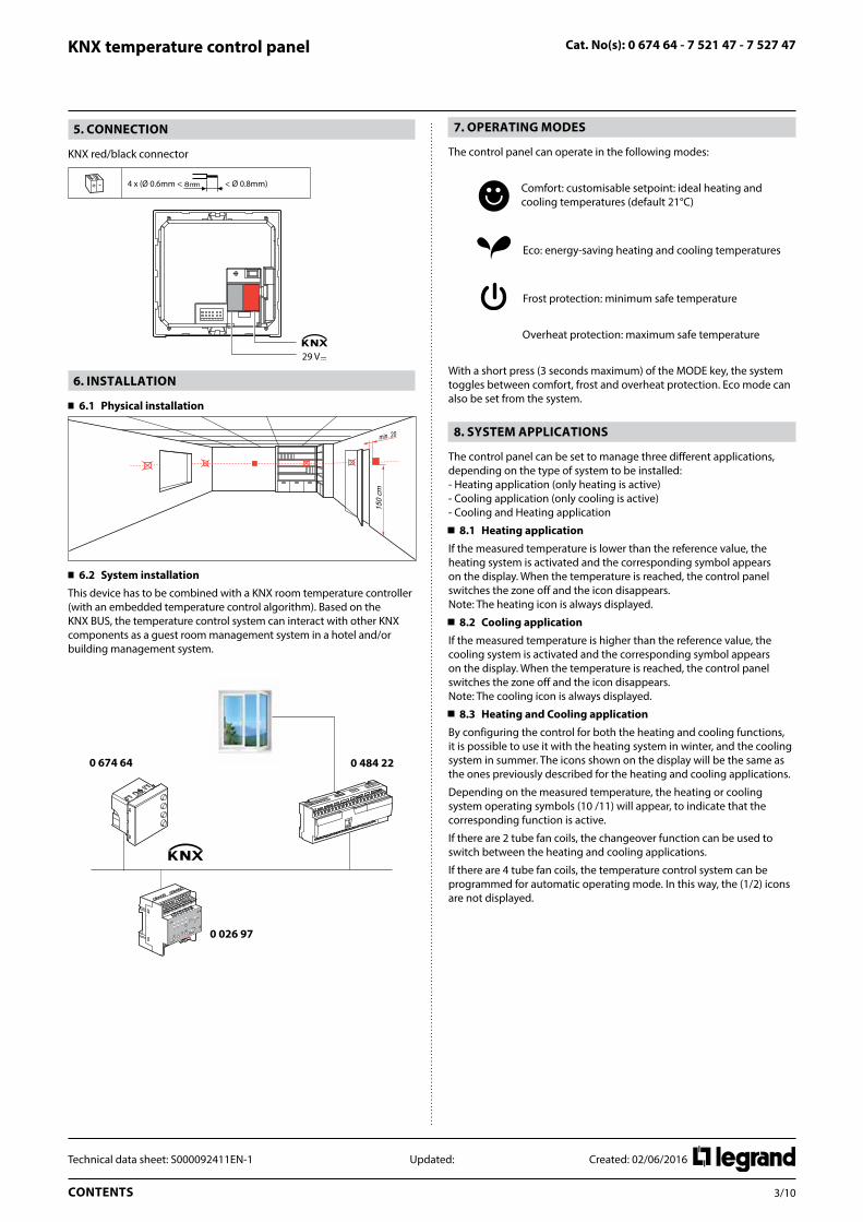
7. OPEraTINg MODES
The control panel can operate in the following modes:
Comfort: customisable setpoint: ideal heating and cooling temperatures (default 21°C)
Eco: energy-saving heating and cooling temperatures
Frost protection: minimum safe temperature
Overheat protection: maximum safe temperature
With a short press (3 seconds maximum) of the MODE key, the system toggles between comfort, frost and overheat protection. Eco mode can also be set from the system.
8. SySTEM aPPlICaTIONS
The control panel can be set to manage three different applications, depending on the type of system to be installed:- Heating application (only heating is active)- Cooling application (only cooling is active)- Cooling and Heating application
8.1 heating application
If the measured temperature is lower than the reference value, the heating system is activated and the corresponding symbol appears on the display. When the temperature is reached, the control panel switches the zone off and the icon disappears. Note: The heating icon is always displayed.
8.2 Cooling application
If the measured temperature is higher than the reference value, the cooling system is activated and the corresponding symbol appears on the display. When the temperature is reached, the control panel switches the zone off and the icon disappears. Note: The cooling icon is always displayed.
8.3 heating and Cooling application
By configuring the control for both the heating and cooling functions, it is possible to use it with the heating system in winter, and the cooling system in summer. The icons shown on the display will be the same as the ones previously described for the heating and cooling applications.
Depending on the measured temperature, the heating or cooling system operating symbols (10 /11) will appear, to indicate that the corresponding function is active.
If there are 2 tube fan coils, the changeover function can be used to switch between the heating and cooling applications.
If there are 4 tube fan coils, the temperature control system can be programmed for automatic operating mode. In this way, the (1/2) icons are not displayed.

4/10CONTENTS
Technical data sheet: S000092411EN-1 Updated: Created: 02/06/2016
Cat. No(s): 0 674 64 - 7 521 47 - 7 527 47KNX temperature control panel
9. SETTINgS
9.1 Display during installation
No configuration
MODE
FAN
+
-
MODE
FAN
+
-
MODE
FAN
+
-
MODE
FAN
+
-
MODE
FAN
+
-
MODE
FAN
+
-
MODE
FAN
+
-
MODE
FAN
+
-
A
The temperature flashes slowly to indicate that the control panel has not been configured.
Temperature calibration
MODE
FAN
+
-
MODE
FAN
+
-
MODE
FAN
+
-
MODE
FAN
+
-
MODE
FAN
+
-
MODE
FAN
+
-
MODE
FAN
+
-
MODE
FAN
+
-
A
After the product switches ON, wait at least 30 minutes before starting temperature calibration.
Press + and - at the same time (> 7 seconds); the thermometer icon starts flashing quickly. Release the keys.
MODE
FAN
+
-
MODE
FAN
+
-
MODE
FAN
+
-
MODE
FAN
+
-
MODE
FAN
+
-
MODE
FAN
+
-
MODE
FAN
+
-
MODE
FAN
+
-
A
After releasing the keys, you can increase or decrease the temperature detected using + and – . Wait a few seconds, or press MODE or FAN to terminate the procedure.
Programming
MODE
FAN
+
-
MODE
FAN
+
-
MODE
FAN
+
-
MODE
FAN
+
-
MODE
FAN
+
-
MODE
FAN
+
-
MODE
FAN
+
-
MODE
FAN
+
-
A
Press MODE and FAN at the same time (> 7 seconds). The control panel displays Pr (Programming mode). Without further action, the display will revert to its initial status after 30 minutes.
Programming can also be performed by pressing the Prog and Reset button on the back of the display.
9. SETTINgS (continued)
9.2 Display during use
ambient temperature and/or setpoint
MODE
FAN
+
-
MODE
FAN
+
-
MODE
FAN
+
-
MODE
FAN
+
-
MODE
FAN
+
-
MODE
FAN
+
-
MODE
FAN
+
-
MODE
FAN
+
-
A
With ETS, you can choose to display the setpoint (the thermometer icon is not shown) and/or the ambient temperature (the thermometer icon is shown). The temperature unit of measurement is °C or °F and can be chosen via a communication object.
A short press on the MODE button, toggles between Comfort mode and Protection mode.
local setpoint modification
MODE
FAN
+
-
MODE
FAN
+
-
MODE
FAN
+
-
MODE
FAN
+
-
MODE
FAN
+
-
MODE
FAN
+
-
MODE
FAN
+
-
MODE
FAN
+
-
A
Press + or - to change the local setpoint. The new temperature flashes.
After 5 seconds without action, the display stops flashing and the new value is accepted as the new temperature setpoint. The local setpoint can only be modified in Comfort mode.
Fan coil speed
MODE
FAN
+
-
MODE
FAN
+
-
MODE
FAN
+
-
MODE
FAN
+
-
MODE
FAN
+
-
MODE
FAN
+
-
MODE
FAN
+
-
MODE
FAN
+
-
A
If the thermostat is configured for management of a fan coil type load, by pressing the FAN key you can scroll through the fan speeds available, selecting one of the following values.
Press FAN to set the fan speed to the desired level:
MODE
FAN
+
-
MODE
FAN
+
-
MODE
FAN
+
-
MODE
FAN
+
-
MODE
FAN
+
-
MODE
FAN
+
-
MODE
FAN
+
-
MODE
FAN
+
-
A
MODE
FAN
+
-
MODE
FAN
+
-
MODE
FAN
+
-
MODE
FAN
+
-
MODE
FAN
+
-
MODE
FAN
+
-
MODE
FAN
+
-
MODE
FAN
+
-
A
MODE
FAN
+
-
MODE
FAN
+
-
MODE
FAN
+
-
MODE
FAN
+
-
MODE
FAN
+
-
MODE
FAN
+
-
MODE
FAN
+
-
MODE
FAN
+
-
A
MODE
FAN
+
-
MODE
FAN
+
-
MODE
FAN
+
-
MODE
FAN
+
-
MODE
FAN
+
-
MODE
FAN
+
-
MODE
FAN
+
-
MODE
FAN
+
-
A
Speed 1
Speed 2
Speed 3
Automatic operation
5/10CONTENTS
Technical data sheet: S000092411EN-1 Updated: Created: 02/06/2016
Cat. No(s): 0 674 64 - 7 521 47 - 7 527 47KNX temperature control panel
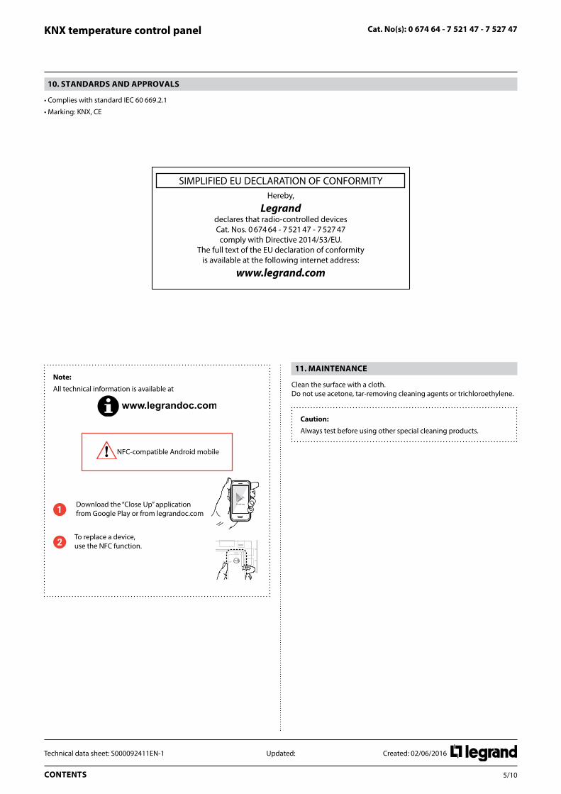
10. STaNDarDS aND aPPrOvalS
• Complies with standard IEC 60 669.2.1
• Marking: KNX, CE
SIMPLIFIED EU DECLARATION OF CONFORMITYHereby,
Legranddeclares that radio-controlled devices Cat. Nos. 0 674 64 - 7 521 47 - 7 527 47
comply with Directive 2014/53/EU. The full text of the EU declaration of conformity
is available at the following internet address:
www.legrand.com
11. MaINTENaNCE
Clean the surface with a cloth. Do not use acetone, tar-removing cleaning agents or trichloroethylene.
Caution:
Always test before using other special cleaning products.
Note:
All technical information is available at
NFC-compatible Android mobile
1 Download the “Close Up” application from Google Play or from legrandoc.com
2 To replace a device, use the NFC function.
6/10CONTENTS
Technical data sheet: S000092411EN-1 Updated: Created: 02/06/2016
Cat. No(s): 0 674 64 - 7 521 47 - 7 527 47KNX temperature control panel
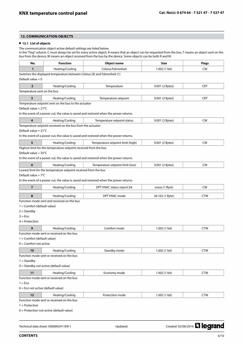
12. COMMUNICaTION ObjECTS
12.1 list of objects
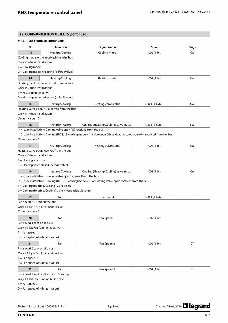
The communication object active default settings are listed below. In the “Flag” column, C must always be set for every active object, R means that an object can be requested from the bus, T means an object sent on the bus from the device, W means an object received from the bus by the device. Some objects can be both R and W.
No. Function Object name Size Flags
1 Heating/Cooling Celsius/Fahrenheit 1.002 (1 bit) CW
Switches the displayed temperature between Celsius (0) and Fahrenheit (1)
Default value = 0
2 Heating/Cooling Temperature 9.001 (2 Bytes) CRT
Temperature sent on the bus
3 Heating/Cooling Temperature setpoint 9.001 (2 Bytes) CRT
Temperature setpoint sent on the bus to the actuator
Default value = 21°C
In the event of a power cut, the value is saved and restored when the power returns.
4 Heating/Cooling Temperature setpoint status 9.001 (2 Bytes) CW
Temperature setpoint received on the bus from the actuator
Default value = 21°C
In the event of a power cut, the value is saved and restored when the power returns.
5 Heating/Cooling Temperature setpoint limit (high) 9.001 (2 Bytes) CW
Highest limit for the temperature setpoint received from the bus
Default value = 35°C
In the event of a power cut, the value is saved and restored when the power returns.
6 Heating/Cooling Temperature setpoint limit (low) 9.001 (2 Bytes) CW
Lowest limit for the temperature setpoint received from the bus
Default value = 7°C
In the event of a power cut, the value is saved and restored when the power returns.
7 Heating/Cooling DPT HVAC status report bit xxxxx (1 Byte) CW
8 Heating/Cooling DPT HVAC mode 20.102 (1 Byte) CTW
Function mode sent and received on the bus
1 = Comfort (default value)
2 = Standby
3 = Eco
4 = Protection
9 Heating/Cooling Comfort mode 1.002 (1 bit) CTW
Function mode sent or received on the bus
1 = Comfort (default value)
0 = Comfort not active
10 Heating/Cooling Standby mode 1.002 (1 bit) CTW
Function mode sent or received on the bus
1 = Standby
0 = Standby not active (default value)
11 Heating/Cooling Economy mode 1.002 (1 bit) CTW
Function mode sent or received on the bus
1 = Eco
0 = Eco not active (default value)
12 Heating/Cooling Protection mode 1.002 (1 bit) CTW
Function mode sent or received on the bus
1 = Protection
0 = Protection not active (default value)
7/10CONTENTS
Technical data sheet: S000092411EN-1 Updated: Created: 02/06/2016
Cat. No(s): 0 674 64 - 7 521 47 - 7 527 47KNX temperature control panel
12. COMMUNICaTION ObjECTS (continued)
12.1 list of objects (continued)
No. Function Object name Size Flags
13 Heating/Cooling Cooling mode 1.002 (1 bit) CW
Cooling mode active received from the bus
Only in 2-tube installations
1 = Cooling mode
0 = Cooling mode not active (default value)
14 Heating/Cooling Heating mode 1.002 (1 bit) CW
Heating mode active received from the bus
Only in 2-tube installations
1 = Heating mode active
0 = Heating mode not active (default value)
15 Heating/Cooling Heating valve status 5.001 (1 byte) CW
Heating valve open (%) received from the bus
Only in 4-tube installations
Default value = 0
16 Heating/Cooling Cooling (Heating/Cooling) valve status 5.001 (1 byte) CW
In 4-tube installation: Cooling valve open (%) received from the bus
In 2-tube installation: Cooling (if OBJ13 cooling mode = 1) valve open (%) or Heating valve open (%) received from the bus
Default value = 0
17 Heating/Cooling Heating valve status 1.002 (1 bit) CW
Heating valve open received from the bus
Only in 4-tube installations
1 = Heating valve open
0 = Heating valve closed (default value)
18 Heating/Cooling Cooling (Heating/Cooling) valve status 1.002 (1 bit) CW
In 4-tube installation: Cooling valve open received from the bus
In 2-tube installation: Cooling (if OBJ13 cooling mode = 1) or Heating valve open received from the bus
1 = Cooling (Heating/Cooling) valve open
0 = Cooling (Heating/Cooling) valve closed (default value)
19 Fan Fan Speed 5.001 (1 byte) CT
Fan speed (%) sent on the bus
Only if 1-byte Fan function is active
Default value = 0
20 Fan Fan Speed 1 1.002 (1 bit) CT
Fan speed 1 sent on the bus
Only if 1-bit Fan function is active
1 = Fan speed 1
0 = Fan speed off (default value)
21 Fan Fan Speed 2 1.002 (1 bit) CT
Fan speed 2 sent on the bus
Only if 1-byte Fan function is active
1 = Fan speed 2
0 = Fan speed off (default value)
22 Fan Fan Speed 3 1.002 (1 bit) CT
Fan speed 3 sent on the bus1 = Standby
Only if 1-bit Fan function bit is active
1 = Fan speed 3
0 = Fan speed off (default value)
8/10CONTENTS
Technical data sheet: S000092411EN-1 Updated: Created: 02/06/2016
Cat. No(s): 0 674 64 - 7 521 47 - 7 527 47KNX temperature control panel
12. COMMUNICaTION ObjECTS (continued)
12.1 list of objects (continued)
No. Function Object name Size Flags
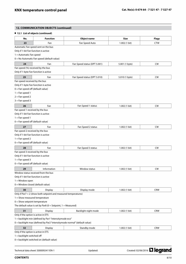
23 Fan Fan Speed Auto 1.002 (1 bit) CTW
Automatic Fan speed sent on the bus
Only if 1-bit Fan function is active
1 = Automatic Fan speed
0 = No Automatic Fan speed (default value)
24 Fan Fan Speed status (DPT 5.001) 5.001 (1 byte) CW
Fan speed (%) received by the bus
Only if 1-byte Fan function is active
25 Fan Fan Speed status (DPT 5.010) 5.010 (1 byte) CW
Fan speed received by the bus
Only if 1-byte Fan function is active
0 = Fan speed off (default value)
1 = Fan speed 1
2 = Fan speed 2
3 = Fan speed 3
26 Fan Fan Speed 1 status 1.002 (1 bit) CW
Fan speed 1 received by the bus
Only if 1-bit Fan function is active
1 = Fan speed 1
0 = Fan speed off (default value)
27 Fan Fan Speed 2 status 1.002 (1 bit) CW
Fan speed 2 received by the bus
Only if 1-bit Fan function is active
1 = Fan speed 2
0 = Fan speed off (default value)
28 Fan Fan Speed 3 status 1.002 (1 bit) CW
Fan speed 3 received by the bus
Only if 1-bit Fan function is active
1 = Fan speed 3
0 = Fan speed off (default value)
29 Information Window status 1.002 (1 bit) CW
Window status received from the bus
Only if 1-bit Fan function is active
1 = Window open
0 = Window closed (default value)
30 Display Display mode 1.002 (1 bit) CRW
Only if Par7 = 2 (show both setpoint and measured temperatures)
1 = Show measured temperature
0 = Show setpoint temperature
The default value is set by Par8 (0 = Setpoint, 1 = Measured)
31 Display Backlight night mode 1.002 (1 bit) CRW
Only if the option is active in ETS
1 = backlight min (defined by Par1 “intensitymode eco”
0 = backlight max (defined by Par2 “intensitymode normal” (default value)
32 Display Standby mode 1.002 (1 bit) CRW
Only if the option is active in ETS
1 = backlight switched off
0 = backlight switched on (default value)

9/10CONTENTS
Technical data sheet: S000092411EN-1 Updated: Created: 02/06/2016
Cat. No(s): 0 674 64 - 7 521 47 - 7 527 47KNX temperature control panel
12. COMMUNICaTION ObjECTS (continued)
12.2 ETS parameters
List of parameters
The parameters are listed below:
Show on display:
With this parameter you can choose which information to show on the display:
1 – Always setpoint
The monitor will always show the setpoint temperature, the measured temperature will only be displayed during the calibration procedure.
2 – Always measured temperature
The monitor will always show the measured temperature, the setpoint temperature will only be displayed during the change setpoint procedure.
3 – Allow display changing
The monitor will display both temperatures; you’ll be able to change it by using object 30 or holding down the Mode pushbutton.
Default display:
With this parameter you can choose which information to show by default on the display.
This parameter is only active if the parameter “Show display” is “Allow display changing”.
1 – Setpoint
2 – Measured temperature
Intensity mode normal:
With this parameter (1-100%) you can choose the maximum intensity of the backlight.
This intensity will be the default backlight.
Use ECO/NOrMal mode:
With this parameter you can decide whether or not to use the ECO display mode.
If YES, you can define the backlight ECO Intensity mode (0-100%).
You will then be able to switch between normal and eco display mode by using object 31.
When the display is in ECO mode, it will automatically switch the backlight to normal mode after a button is pressed; it will revert to ECO after 30 s of inactivity.
12. COMMUNICaTION ObjECTS (continued)
12.2 ETS parameters (continued)
activate standby mode:
With this parameter you can decide whether or not to use the standby display mode (monitor switch OFF).
If YES, you will then be able to switch between normal and standby display mode by using object 32.
When the display is in standby mode, it will automatically switch the backlight to normal mode after a button is pressed; it will revert to standby after 30 s of inactivity.
Mode change:
Disable – a short press on the “mode pushbutton” will have no effect. Enable – with a short press on the “mode pushbutton” you can switch between COMFORT and PROTECTION modes.
Temperature sending:
Cyclical – the device will send the measured temperature on the bus cyclically; the delay between two frames is configurable by a parameter. Cyclic frequency – the parameter Changing step is not active.
On Change – the device will send the measured temperature on the bus following a change of temperature, the step is configurable by a parameter Changing step, the parameter Cyclic frequency is not active.
Cyclical + On Change – the device will send the measured temperature on the bus cyclically (configurable by parameter Cyclic frequency) and following a change (configurable by the parameter Changing step).
Offset temperature:
With this parameter (interval: 0.1°C, limits: -9.9°C +9.9°C) you can adjust the temperature measured by the device depending on the installation conditions.
You can even change this parameter locally with the calibration procedure (long press on both + and – pushbuttons).

10/10CONTENTS
Technical data sheet: S000092411EN-1 Updated: Created: 02/06/2016
Cat. No(s): 0 674 64 - 7 521 47 - 7 527 47KNX temperature control panel
12. COMMUNICaTION ObjECTS (continued)
12.2 ETS parameters (continued)
base Setpoint temperature:
This parameter (interval: 0.1°C) represents the default setpoint temperature of the system.
Every time the system mode switches between Comfort and ECO this setpoint will be sent on the bus.
In this way Comfort mode will return to the default setpoint (even if the customer had previously changed it) and ECO mode will always have the same setpoint (“Base Setpoint – actuator delta” in the Heating function or “Base Setpoint + actuator delta” in the Cooling function).
Number of tubes:
With this parameter you have to define whether the system is working with 2 or 4 tubes, the choice must be the same as for the actuator working with the thermostat.
2 tubes – the icons for the Heating/Cooling functions and Heating ON/Cooling ON will depend on objects 13 and 14 as explained in the object section. Objects 15 and 17 will be inactive (there is only one valve).
4 tubes – the icons for the Heating/Cooling functions and objects 13 and 14 will be inactive (there is no need for the Heating/Cooling functions as the system is able to heat and cool at the same time).
Insensitive zone between heating/cooling:
Only for 4-tube installations (or 2-tube installations with automatic changeover between Heating and Cooling) you MUST configure this parameter with the same value as the corresponding parameter on the actuator. In 2-tube installations without change between heating and cooling the parameter is zero.
This is useful when the actuator is in cooling mode and sends back a different setpoint on the bus (setpoint status = setpoint + insensitive zone); in this case the display will show the setpoint sent instead of the status.
Type of object for valve:
With this parameter you can choose the type of object (1 bit or 1 byte) to communicate the status of the heating/cooling valve(s).
The choice must be the same as for the actuator.
1 bit – objects 15 – 16 are not active, objects 17-18 are active.
1 byte – objects 17 – 18 are not active, objects 15-16 are active.
add Object ”hvaC mode”:
If yes, object 8 (HVAC mode) is active.
add Object ”hvaC Status”:
If yes, object 7 (HVAC status report bit) is active.
To be used only with actuators using the same object.
add temp. setpoint limit objects:
If yes, objects 5 and 6 (Temperature setpoint limit (high) and (low)) are active.
If not, the setpoint limits are fixed (7°C and 35°C).
Use Fan functions:
If No, no other parameter, Fan object or Fan icon is available.
If Yes, you can use the Fan functions.
12. COMMUNICaTION ObjECTS (continued)
12.2 ETS parameters (continued)
Fan Speed setpoint type:
With this parameter you can choose the type of object (1 bit or 1 byte) to communicate the speed of the fan.
The choice must be the same as for the actuator.
1 bit – objects 19, 24, 25 and the “setpoint fan speed 1, 2, 3” parameters are not active, objects 20, 21, 22, 26, 27, 28 are active.
1 byte – objects 20, 21, 22, 26, 27, 28 are not active, objects 19, 24, 25 are active.
Fan Speed setpoint 1:
Only if Fan Speed setpoint type = 1 Byte.
This is the fan speed value (%) sent on the bus (Object 24) by the control panel when speed 1 is selected via Pushbutton.
It is also the highest limit (if Object 24 <= Fan speed setpoint 1) to display the Fan speed 1 icon.
Fan Speed setpoint 2:
Only if Fan Speed setpoint type = 1 Byte.
This is the fan speed value (%) sent on the bus (Object 24) by the control panel when speed 2 is selected via Pushbutton.
It is also the highest limit (if Fan speed setpoint 1 < Object 24 <= Fan speed setpoint 2) to display the Fan speed 1 and 2 icons and the lowest limit (if Fan speed setpoint 2 < Object) to display the Fan speed 1, 2 and 3 icons.
Fan Speed setpoint 3:
Only if Fan Speed setpoint type = 1 Byte.
This is the fan speed value (%) sent on the bus (Object 24) by the control panel when speed 3 is selected via Pushbutton.