Embed Size (px)
Citation preview
N. TAYLOR, European Commission JRC (Luxembourg)D.P.G. LIDBURY, Serco Assurance (United Kingdom)Improving Structural Integrity Assessment Techniques
N. Taylor1)
and D.P.G. Lidbury2)
1) European Commission Joint Research Centre, Institute for Energy, The Netherlands (NESC
Network Manager) 2)
Serco Assurance, Risley, UK (NESC Network Chairman)
Abstract
The Network for Evaluating Structural Components (NESC) was set up over 10 years ago to
address the verification of advanced structural integrity assessment techniques for safety-
critical reactor components. Through its self-funded activities and associated projects, partly
funded by the European Commission’s DG-RTD, it has developed a significant body of
benchmark R&D data, in particular for large-scale tests performed under closely monitored
conditions. Key developments are described in three areas a) fracture assessment for reactor
pressure vessels; b) fracture assessment of dissimilar metal welds in primary piping and c)
thermal fatigue damage in class 1 and class 2 piping. The added value of combining the
efforts of utilities, manufacturers and R&D organisations is stressed.
1 Introduction
Dealing with real or postulated cracks in large structures is a classical engineering problem,
which takes on special significance for components in nuclear power plants. While regulators,
utilities and plant manufacturers have developed effective procedures to assess structural
integrity, a policy of continuous development is required to ensure that safety margins are
maintained as plants accumulate many years of service and that robust technical justifications
can be made for inspection and maintenance performance requirements.
Advanced techniques typically rely on calibration from measurement of fracture toughness or
fatigue parameters on small laboratory specimens. In the case of brittle fracture, for instance,
there is now wide acceptance of methods such as Master Curve to assess shifts in the
transition behaviour from as-received to end-of-life states. However there remain obstacles to
the application of such laboratory-generated representations of the fracture transition
behaviour for assessing postulated defects in critical components. The pattern of crack-tip
stresses and strains causing plastic flow and fracture in components is different to that in test
specimens due to differences in both geometry and loading. This gives rise to the so-calledconstraint e_ect, which in many cases can be less in components than in test specimens,
leading to higher effective fracture toughness. Other factors also play a role: uncertainty
regarding local loading conditions, reliability of assumptions of postulated flaws, crack front
length (cleavage site sampling effect), representativeness of the laboratory materials data to
the component; local variations and/or gradients in materials properties and environment.
Finally, the methods use to make the assessment must be verified and have the confidence of
the plant operator and safety authority.
In response to such challenges the Network for Evaluation of Structural Components (NESC)
has worked over the last 10 years to:
- create an international network to undertake collaborative projects capable of
validating the entire structural integrity process.
- support the development of best practices and the harmonisation of standards.
- improve codes and standards for structural integrity assessment and to transfer the
technology to industrial applications.
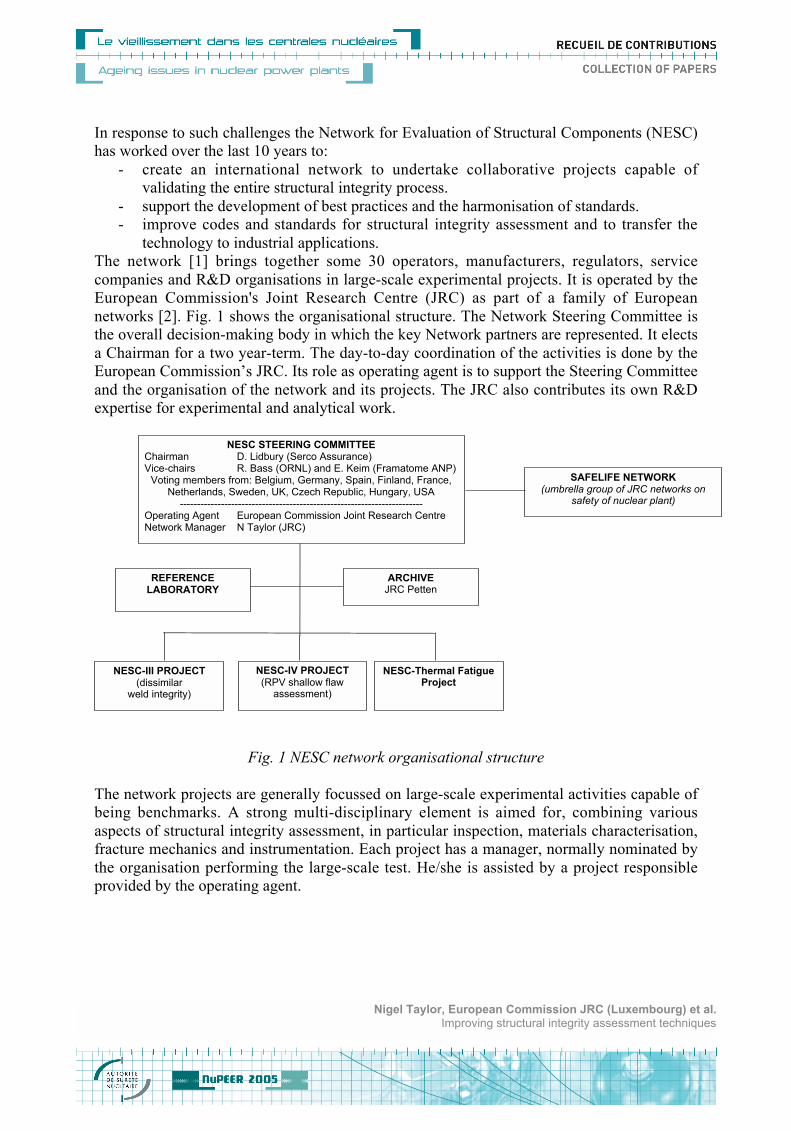
The network [1] brings together some 30 operators, manufacturers, regulators, service
companies and R&D organisations in large-scale experimental projects. It is operated by the
European Commission's Joint Research Centre (JRC) as part of a family of European
networks [2]. Fig. 1 shows the organisational structure. The Network Steering Committee is
the overall decision-making body in which the key Network partners are represented. It elects
a Chairman for a two year-term. The day-to-day coordination of the activities is done by the
European Commission’s JRC. Its role as operating agent is to support the Steering Committee
and the organisation of the network and its projects. The JRC also contributes its own R&D
expertise for experimental and analytical work.
Fig. 1 NESC network organisational structure
The network projects are generally focussed on large-scale experimental activities capable of
being benchmarks. A strong multi-disciplinary element is aimed for, combining various
aspects of structural integrity assessment, in particular inspection, materials characterisation,
fracture mechanics and instrumentation. Each project has a manager, normally nominated by
the organisation performing the large-scale test. He/she is assisted by a project responsible
provided by the operating agent.
SAFELIFE NETWORK (umbrella group of JRC networks on
safety of nuclear plant)
NESC STEERING COMMITTEE Chairman D. Lidbury (Serco Assurance) Vice-chairs R. Bass (ORNL) and E. Keim (Framatome ANP)
Voting members from: Belgium, Germany, Spain, Finland, France, Netherlands, Sweden, UK, Czech Republic, Hungary, USA
----------------------------------------------------------------------- Operating Agent European Commission Joint Research Centre Network Manager N Taylor (JRC)
ARCHIVE JRC Petten
REFERENCE LABORATORY
NESC-Thermal Fatigue Project
NESC-III PROJECT (dissimilar
weld integrity)
NESC-IV PROJECT (RPV shallow flaw
assessment)
Nigel Taylor, European Commission JRC (Luxembourg) et al.Improving structural integrity assessment techniques
Two projects have been completed and three are currently running, as indicated in Table 1.
The set of coordinated experimental and analytical studies making up each project are funded
primarily through so-called “in-kind” contributions, whereby participating organisations
contribute work and are then entitled to have access to the contributions of others to any given
project. Members have also benefited from the shared cost actions (SCAs) of the European
Commission’s Research Framework Programmes. In many cases these small dedicated
research projects have been pilot or seed projects for subsequent larger Network supported
actions. Examples of areas being explored for future NESC activities include: verification of
the warm pre-stress assessment methods (extension of the SMILE shared cost action [8]) and
fracture analysis of flaws in repair welds.
Table 1 – NESC Network Projects
Project Main Test Duration
NESC-I spinning cylinder [3] Spinning cylinder pressurised thermal shock(PTS) test performed by AEA Technology inMarch 1997 (main test sponsor HSE)
1993-2001
NESC-II Brittle crack initiation,propagation and arrest of shallowcracks in a clad vessel underPTS loading [4]
Two PTS tests on cylinders with shallow cracksperformed by MPA Stuttgart in 2000/2001 (maintest sponsor BMFT)
1999-2003
NESC-III [5] Integrity of dissimilarmetal welds
Large-scale test on a dissimilar weld pipeassembly (performed by EDF, as part of theADIMEW SCA)
2001-2005
NESC-IV [6] Investigation of thetransferability of Master Curvetechnology to shallow flaws inreactor pressure vesse lapplications
Biaxial bend tests on large cruciform-type testpieces with surface-breaking semi-ellipticdefects and uniaxial bend tests on beams withsimulated sub-surface flaws (performed byORNL as part of the HSST programme)
2001-2005
NESC-TF Thermal Fatigue [7] Database of thermal fatigue data for operatingcomponents and mocks has been created
2003
Looking to the future, the NESC Steering Committee foresees the continuation of its work as
part of an integrated, networked effort in the area of plant life assessment. Several leading
members have been instrumental in submitting a concept document to the European
Commission’s DG-RTD for a European Network on Structural Integrity Research
(SIRENET), to be funded under Framework Programme 6 using the Network of Excellence
mechanism. It stresses the need to create an organisational structure capable of working at
European level to produce and exploit R&D in support of the safe and competitive operation
of nuclear power plants, recognising that the majority of reactors have now been operating for
longer than 20 years and their continuing safe operation needs to be supported by effective
lifetime management tools.
Nigel Taylor, European Commission JRC (Luxembourg) et al.Improving structural integrity assessment techniques
2 Reactor Pressure Vessel Integrity
Integrity of pressurised water reactor pressure vessels (RPVs), in particular under design-base
pressurised thermal shock (PTS) conditions has been a major focus of NESC activities. The
following sections summarise the impact of these projects on different aspects of advanced
structural integrity assessment methodologies in some selected areas. In this respect the
Network has collaborated closely with the VOCALIST shared cost action project (Validation
of Constraint-Based Assessment Methodology in Structural Integrity) [9].
2.1 Direct evidence of resistance to brittle fracture
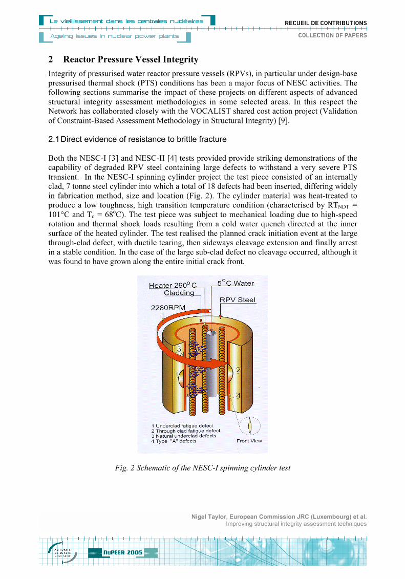
Both the NESC-I [3] and NESC-II [4] tests provided provide striking demonstrations of the
capability of degraded RPV steel containing large defects to withstand a very severe PTS
transient. In the NESC-I spinning cylinder project the test piece consisted of an internally
clad, 7 tonne steel cylinder into which a total of 18 defects had been inserted, differing widely
in fabrication method, size and location (Fig. 2). The cylinder material was heat-treated to
produce a low toughness, high transition temperature condition (characterised by RTNDT =
101°C and To = 68oC). The test piece was subject to mechanical loading due to high-speed
rotation and thermal shock loads resulting from a cold water quench directed at the inner
surface of the heated cylinder. The test realised the planned crack initiation event at the large
through-clad defect, with ductile tearing, then sideways cleavage extension and finally arrest
in a stable condition. In the case of the large sub-clad defect no cleavage occurred, although it
was found to have grown along the entire initial crack front.
Fig. 2 Schematic of the NESC-I spinning cylinder test
Nigel Taylor, European Commission JRC (Luxembourg) et al.Improving structural integrity assessment techniques
In the case of NESC-II, two large-scale tests were conducted using the special facility
developed at MPA Stuttgart. The test pieces were thick-walled cylinders of outer diameter
800 mm and wall thickness 190 mm, fabricated in a 17 MoV 8 4 mod steel with a two-layer
austenitic cladding on the internal surface. The base material was heat-treated to produce a
low toughness, high transition temperature condition (characterised by RTNDT = 130°C, To =
66oC and a low upper-shelf Charpy impact energy of 70 J). In the test on the NP1 cylinder,
containing two shallow semi-elliptical through-clad defects of depth 21 mm and length 60
mm, although the planned loading transient was achieved, no growth occurred. The test on the
NP2 cylinder, with a fully circumferential sub-clad defect, produced a crack growth and arrest
event; with a maximum extension of approximately 15 mm. Post-test metallography however
revealed that the growth mode was intergranular.
2.2 Safety Margins in Code-Based Assessments
For the NESC-I defects a study was made [10] using several national codes: ASME XI
(USA), R6 (UK), BS PD6493:1991 (UK), SKIFS 1994:1 (Sweden), KTA (Germany), and
RCCM/RSEM (France). All the assessments predicted very small allowable defect depths, in
the range 1 mm to 9 mm deep. This contrasts with behaviour during the test, in which only
limited crack growth took place from defects over 70 mm deep. The conservatism in code
assessments springs from a combination of the methods used to estimate crack driving force,
the defect model adopted, and the assumed fracture toughness response. The resulting
recommendations, which were reinforced by an analogous NESC-II study, included:
- Excess pessimism in predictions of crack driving force can be minimised by use of an
appropriate defect model (through-clad for surface defects, sub-clad for buried defects),
and by taking account of secondary stress relaxation in estimates of crack driving force.
- Fracture toughness curves based upon the traditional ASME approach with safety factors
are very pessimistic for the NESC-I and NESC-II materials, whereas a statistical lower
bound based upon the Master Curve provides a much better description of the material
behaviour.
- Assessments should take proper account of differing material zones such as the cladding
and HAZ where suitable fracture toughness data exists.
2.3 Master Curve Representation of the Transition Curve
The Master Curve method [11,12,13] has been used consistently in NESC to capture the
intrinsically statistical nature of cleavage in the transition range and to allow direct use of
fracture data in the assessment process. This has involved extensive testing programmes, each
of which typically involved several specimen types: CT-25, SENB 10x20 mm and SENB
10x20 mm. In all this database now covers 4 distinct materials:
• Artificially embrittled A508 Cl. 3, used for the NESC-I cylinder
• Artificially embrittled 17 MoV 8 4 mod, used for the NESC-II cylinders
• A508 B weld (SAW, Class 1 filler), used for the NESC-IV biaxial tests
• A508 B plate, used for the NESC-IV embedded flaw tests
Nigel Taylor, European Commission JRC (Luxembourg) et al.Improving structural integrity assessment techniques
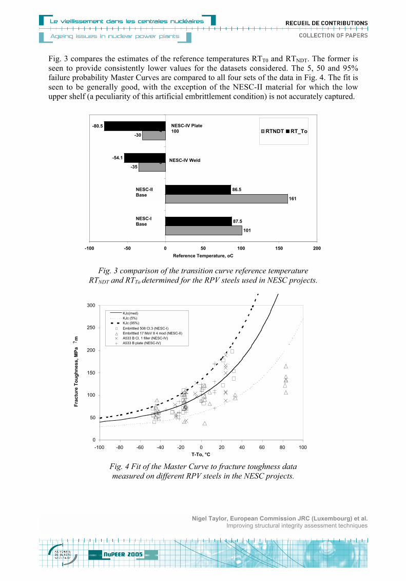
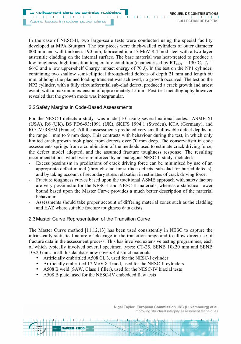
Fig. 3 compares the estimates of the reference temperatures RTT0 and RTNDT. The former is
seen to provide consistently lower values for the datasets considered. The 5, 50 and 95%
failure probability Master Curves are compared to all four sets of the data in Fig. 4. The fit is
seen to be generally good, with the exception of the NESC-II material for which the low
upper shelf (a peculiarity of this artificial embrittlement condition) is not accurately captured.
101
161
-35
-30
87.5
86.5
-54.1
-80.5
-100 -50 0 50 100 150 200
1
2
3
4
Reference Temperature, oC
RTNDT RT_ToNESC-IV Plate
100
NESC-IV Weld
NESC-II
Base
NESC-I
Base
Fig. 3 comparison of the transition curve reference temperature
RTNDT and RTTo determined for the RPV steels used in NESC projects.
0
50
100
150
200
250
300
-100 -80 -60 -40 -20 0 20 40 60 80 100
T-To, °C
Fra
ctu
re T
ou
gh
ne
ss
, M
Pa
?m
KJc(med)
KJc (5%)
KJc (95%)
Embrittled 508 Cl.3 (NESC-I)
Embrittled 17 MoV 8 4 mod (NESC-II)
A533 B Cl. 1 filler (NESC-IV)
A533 B plate (NESC-IV)
Fig. 4 Fit of the Master Curve to fracture toughness data
measured on different RPV steels in the NESC projects.
Nigel Taylor, European Commission JRC (Luxembourg) et al.Improving structural integrity assessment techniques
A feature of the materials testing performed for the NESC projects has been the systemic
inclusion of shallow-crack specimens (0.1 a/W 0.2) to quantify constraint loss effects.
Fig. 5 shows the shift in To i.e. the difference between the To estimate for the shallow crack
specimens and that for standard deep crack specimens) as a function of the normalised T-
stress parameter (the T-stress [14] at the limit load for the specimen type divided by the yield
stress). It is seen that the shallow flaw effect can reduce To by up to 40oC relative to that for
deep flawed CT and SENB specimens (a/W 0.5). Such data is essential for calibrating
fracture mechanics constraint loss models.
-80
-60
-40
-20
0
20
40
-1 -0.8 -0.6 -0.4 -0.2 0 0.2 0.4
Normalised T-stress, T/yield stress
Sh
ift
in T
o,
°C
Embrittled A508 Cl.3 (NESC-1)
Embrittled 17 MoV 8 4 mod (NESC-2)
A533 B Cl.3 filler (NESC-4)
A533 B Plate (NESC-4)
SENB
a/W=0,1SENB,
a/W=0,5
CT
a/W=0,5
SENB
a/W=0,2
Fig. 5 Illustration of constraint loss effects determined from fracture
tests on materials used in NESC projects.
2.4 Constraint Based-Fracture Mechanics
Advanced fracture mechanics analysis offers a range of possibilities for incorporating
constraint effects into flaw assessment procedures. Study of these and, in particular, verifying
their application to component-like conditions has been a major feature of NESC work.
The NESC-IV project [6, 15] has considered two specific situations in which very different
constraint conditions arise. Following on from the PTS tests, this was a narrowly focussed
experimental/analytical program aimed at developing validated analysis methods for
transferring fracture toughness data generated on standard test specimens to shallow flaws in
reactor pressure vessel welds subject to biaxial loading (representative of PTS conditions) in
the lower-transition temperature region. The benchmark tests performed at the ORNL facility
Nigel Taylor, European Commission JRC (Luxembourg) et al.Improving structural integrity assessment techniques
Nigel Taylor, European Commission JRC (Luxembourg) et al.Improving structural integrity assessment techniques
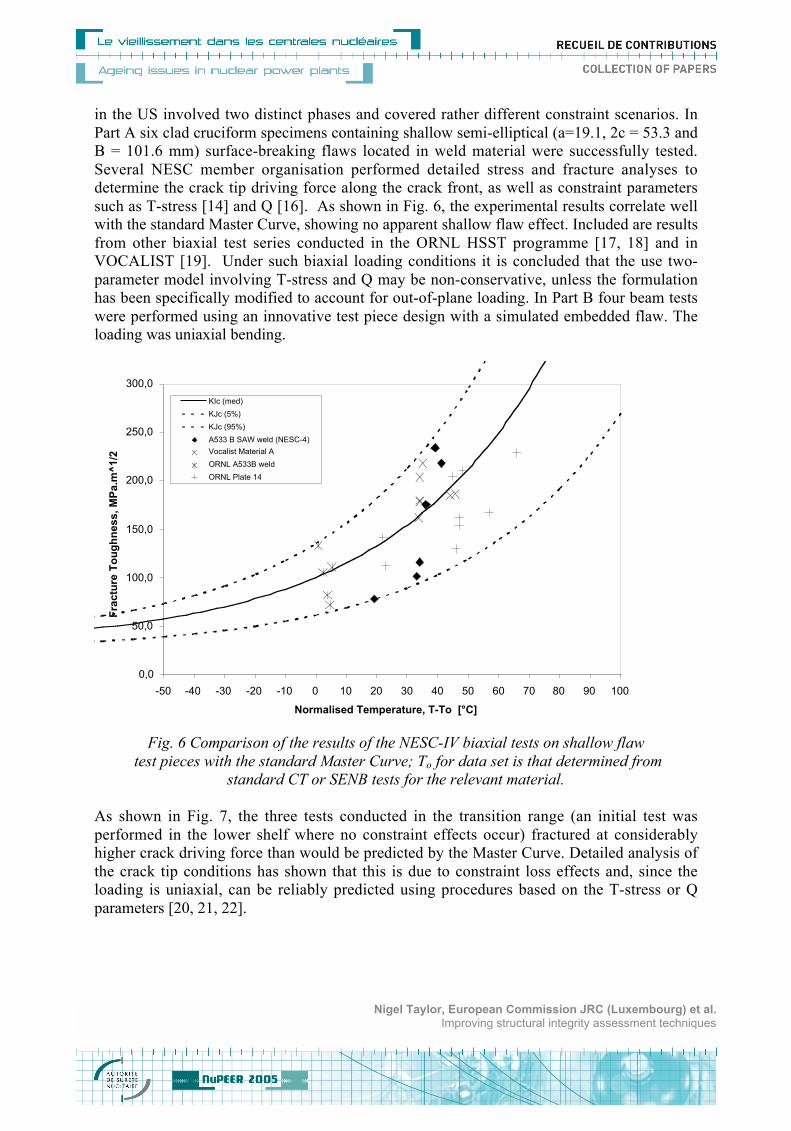
in the US involved two distinct phases and covered rather different constraint scenarios. In
Part A six clad cruciform specimens containing shallow semi-elliptical (a=19.1, 2c = 53.3 and
B = 101.6 mm) surface-breaking flaws located in weld material were successfully tested.
Several NESC member organisation performed detailed stress and fracture analyses to
determine the crack tip driving force along the crack front, as well as constraint parameters
such as T-stress [14] and Q [16]. As shown in Fig. 6, the experimental results correlate well
with the standard Master Curve, showing no apparent shallow flaw effect. Included are results
from other biaxial test series conducted in the ORNL HSST programme [17, 18] and in
VOCALIST [19]. Under such biaxial loading conditions it is concluded that the use two-
parameter model involving T-stress and Q may be non-conservative, unless the formulation
has been specifically modified to account for out-of-plane loading. In Part B four beam tests
were performed using an innovative test piece design with a simulated embedded flaw. The
loading was uniaxial bending.
0,0
50,0
100,0
150,0
200,0
250,0
300,0
-50 -40 -30 -20 -10 0 10 20 30 40 50 60 70 80 90 100
Normalised Temperature, T-To [°C]
Fra
ctu
re T
ou
gh
ne
ss
, M
Pa
.m^
1/2
KIc (med)
KJc (5%)
KJc (95%)
A533 B SAW weld (NESC-4)
Vocalist Material A
ORNL A533B weld
ORNL Plate 14
Fig. 6 Comparison of the results of the NESC-IV biaxial tests on shallow flaw
test pieces with the standard Master Curve; To for data set is that determined from
standard CT or SENB tests for the relevant material.
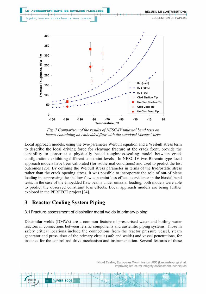
As shown in Fig. 7, the three tests conducted in the transition range (an initial test was
performed in the lower shelf where no constraint effects occur) fractured at considerably
higher crack driving force than would be predicted by the Master Curve. Detailed analysis of
the crack tip conditions has shown that this is due to constraint loss effects and, since the
loading is uniaxial, can be reliably predicted using procedures based on the T-stress or Q
parameters [20, 21, 22].
Nigel Taylor, European Commission JRC (Luxembourg) et al.Improving structural integrity assessment techniques
0
50
100
150
200
250
300
350
400
-150 -130 -110 -90 -70 -50 -30 -10 10
Temperature, °C
Fra
ctu
re T
ou
gh
ne
ss
, M
Pa?m
KJc(med)
KJc (95%)
KJc (5%)
Clad Shallow Tip
Un-Clad Shallow Tip
Clad Deep Tip
Un-Clad Deep Tip
Fig. 7 Comparison of the results of NESC-IV uniaxial bend tests on
beams containing an embedded flaw with the standard Master Curve
Local approach models, using the two-parameter Weibull equation and a Weibull stress term
to describe the local driving force for cleavage fracture at the crack front, provide the
capability to construct a physically based toughness-scaling model between crack
configurations exhibiting different constraint levels. In NESC-IV two Beremin-type local
approach models have been calibrated (for isothermal conditions) and used to predict the test
outcomes [23]. By defining the Weibull stress parameter in terms of the hydrostatic stress
rather than the crack opening stress, it was possible to incorporate the role of out-of plane
loading in suppressing the shallow flaw constraint loss effect, as evidence in the biaxial bend
tests. In the case of the embedded flaw beams under uniaxial loading, both models were able
to predict the observed constraint loss effects. Local approach models are being further
explored in the PERFECT project [24].
3 Reactor Cooling System Piping
3.1 Fracture assessment of dissimilar metal welds in primary piping
Dissimilar welds (DMWs) are a common feature of pressurised water and boiling water
reactors in connections between ferritic components and austenitic piping systems. Those in
safety critical locations include the connections from the reactor pressure vessel, steam
generator and pressuriser of the primary circuit (safe end welds) and vessel penetrations, for
instance for the control rod drive mechanism and instrumentation. Several features of these
Nigel Taylor, European Commission JRC (Luxembourg) et al.Improving structural integrity assessment techniques
Nigel Taylor, European Commission JRC (Luxembourg) et al.Improving structural integrity assessment techniques
welds, such as inspection difficulties, variability of material properties, mixed mode loading
and residual stresses all combine to create challenges for structural integrity assessment,
making them also a natural area of interest for NESC.
During 1996-1999 a group of Network members carried out an EC sponsored project called
BIMET [25, 26]. The two benchmark 3-point bend pipe tests were conducted at room
temperature on a nominal 6" piping assembly, containing a ferritic to stainless steel (A508-
308/309SS-304SS) dissimilar weld with a simulated planar defect at the interface between the
buttering layer and the ferrite pipe material. This lead to a further project called ADIMEW
[27] being launched at the end of 2000 to test a full-scale version of a similar dissimilar weld.
(453 mm diameter pipe, 51 mm wall thickness, A508-308/309SS-316SS material
combination) under four point bending at 300 °C, corresponding to the maximum service
temperature. A simulated defect, consisting of a straight-fronted notch of maximum 17mm
depth, was inserted by electro-erosion at the outer surface in the buttering layer close to the
fusion line of the ferritic steel. This represents a postulated scenario in which an intergranular
corrosion crack would develop on the outer surface. Furthermore, the buttering layer is
considered as a very unfavourable location for such a crack because it is close to the point of
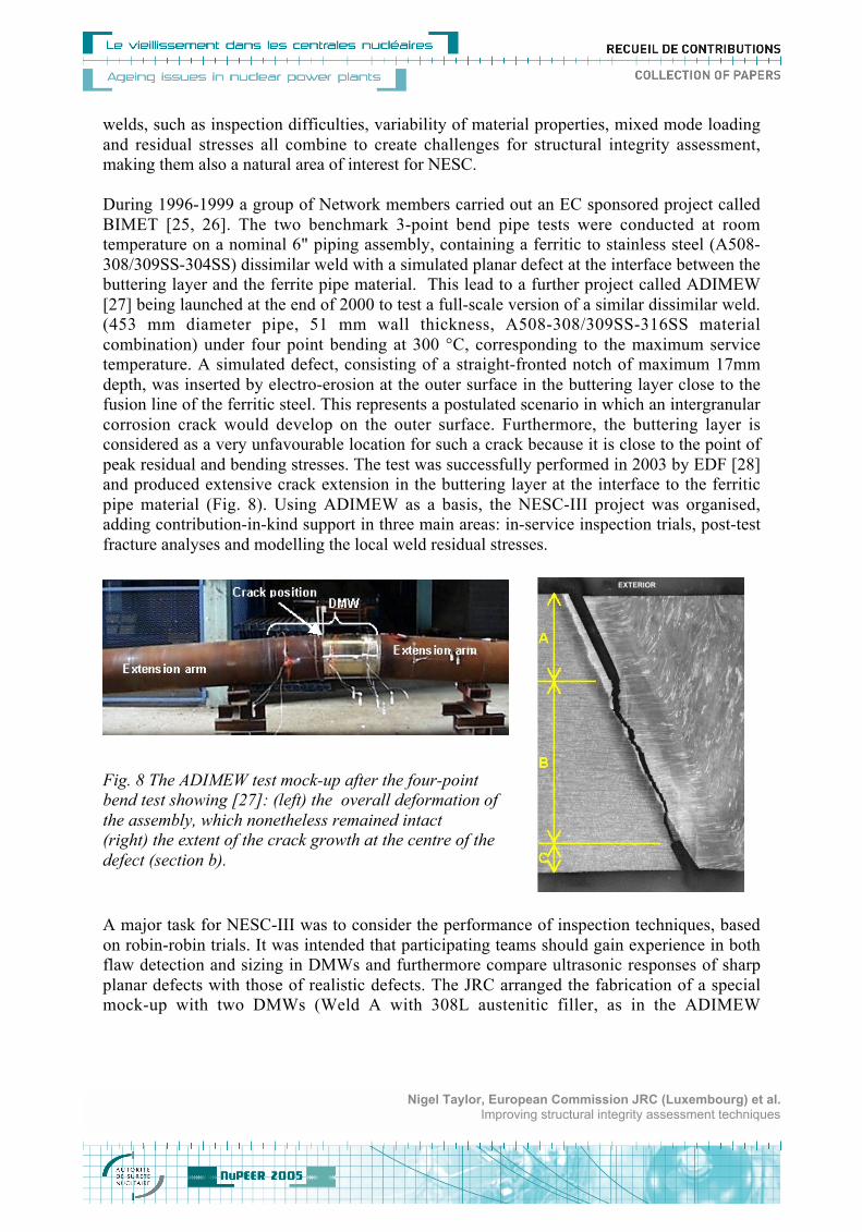
peak residual and bending stresses. The test was successfully performed in 2003 by EDF [28]
and produced extensive crack extension in the buttering layer at the interface to the ferritic
pipe material (Fig. 8). Using ADIMEW as a basis, the NESC-III project was organised,
adding contribution-in-kind support in three main areas: in-service inspection trials, post-test
fracture analyses and modelling the local weld residual stresses.
A major task for NESC-III was to consider the performance of inspection techniques, based
on robin-robin trials. It was intended that participating teams should gain experience in both
flaw detection and sizing in DMWs and furthermore compare ultrasonic responses of sharp
planar defects with those of realistic defects. The JRC arranged the fabrication of a special
mock-up with two DMWs (Weld A with 308L austenitic filler, as in the ADIMEW
Nigel Taylor, European Commission JRC (Luxembourg) et al.Improving structural integrity assessment techniques
Fig. 8 The ADIMEW test mock-up after the four-point
bend test showing [27]: (left) the overall deformation of
the assembly, which nonetheless remained intact
(right) the extent of the crack growth at the centre of the
defect (section b).
component, and Weld B with an Inconel 182 type filler). Both of these contained a series of
simulated defects. The bore of the central ferritic section was clad to make the inspection task
more realistic. The exact location, type and dimensions of the defects are kept strictly secret.
The component was circulated to 7 European inspection teams in 2003-2004. The main
ultrasonic techniques applied were: pulse echo; focused probes; phased array and TOFD. The
JRC then performed a destructive examination to establish the precise shape, dimensions and
location of the simulated defects present in the mock-up. The analysis of the inspection data is
still on-going; however a preliminary assessment [29] has indicated that:
a) Detection performance for Weld A (308L filler) was slightly better than for Weld B
(Inconel 182 filler) with average flaw detection frequencies of 0.88 and 0.75 respectively.
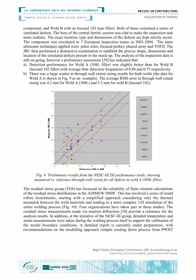
b) There was a large scatter in through wall extent sizing results for both welds (the data for
Weld A is shown in Fig. 9 as an example). The average RMS error in through wall extent
sizing was 4.2 mm for Weld A (308L) and 5.2 mm for weld B (Inconel 182).
0
5
10
15
20
25
30
0 5 10 15 20 25 30
Reference TWE in MM
Me
as
ure
d T
WE
in
MM
AC01
BE01
DF01
DF02
GJ01
HL01
HL02
KM01
NP01
Fig. 9 Preliminary results from the NESC-III ISI performance trials, showing
measured vs. reference through wall extent for all defects in weld A (308L filler)
The residual stress group (TG6) has focussed on the reliability of finite element calculations
of the residual stress distributions in the ADIMEW DMW. This has involved a series of round
robins benchmarks, starting with a simplified approach considering only the thermal
mismatch between the weld materials and leading to a more complex 3-D simulation of the
entire welding process (Fig. 10). Four organisations have taken part in these studies. The
residual stress measurements made via neutron diffraction [30] provide a reference for the
analysis results. In addition, at the initiative of the NESC-III group, detailed temperature and
strain measurements were taken during the welding process itself to support the calibration of
the model boundary conditions. A detailed report is currently under preparation, with
recommendations on the modelling approach (simple cooling down process from PWHT
Nigel Taylor, European Commission JRC (Luxembourg) et al.Improving structural integrity assessment techniques
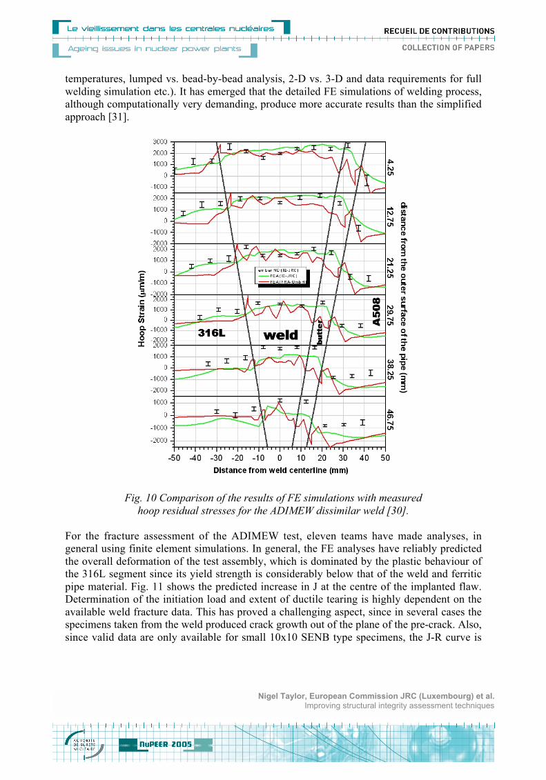
temperatures, lumped vs. bead-by-bead analysis, 2-D vs. 3-D and data requirements for full
welding simulation etc.). It has emerged that the detailed FE simulations of welding process,
although computationally very demanding, produce more accurate results than the simplified
approach [31].
Fig. 10 Comparison of the results of FE simulations with measured
hoop residual stresses for the ADIMEW dissimilar weld [30].
For the fracture assessment of the ADIMEW test, eleven teams have made analyses, in
general using finite element simulations. In general, the FE analyses have reliably predicted
the overall deformation of the test assembly, which is dominated by the plastic behaviour of
the 316L segment since its yield strength is considerably below that of the weld and ferritic
pipe material. Fig. 11 shows the predicted increase in J at the centre of the implanted flaw.
Determination of the initiation load and extent of ductile tearing is highly dependent on the
available weld fracture data. This has proved a challenging aspect, since in several cases the
specimens taken from the weld produced crack growth out of the plane of the pre-crack. Also,
since valid data are only available for small 10x10 SENB type specimens, the J-R curve is
Nigel Taylor, European Commission JRC (Luxembourg) et al.Improving structural integrity assessment techniques
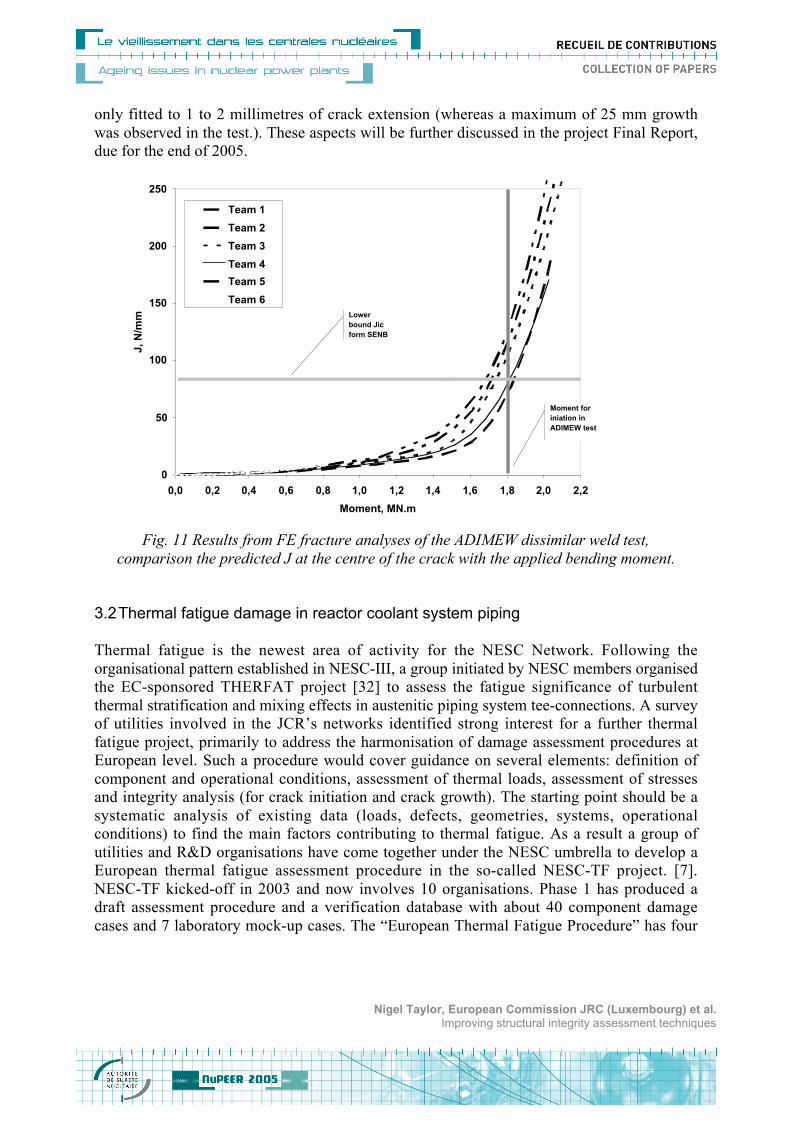
only fitted to 1 to 2 millimetres of crack extension (whereas a maximum of 25 mm growth
was observed in the test.). These aspects will be further discussed in the project Final Report,
due for the end of 2005.
0
50
100
150
200
250
0,0 0,2 0,4 0,6 0,8 1,0 1,2 1,4 1,6 1,8 2,0 2,2
Moment, MN.m
J,
N/m
m
Team 1
Team 2
Team 3
Team 4
Team 5
Team 6
Lower
bound Jic
form SENB
Moment for
iniation in
ADIMEW test
Fig. 11 Results from FE fracture analyses of the ADIMEW dissimilar weld test,
comparison the predicted J at the centre of the crack with the applied bending moment.
3.2 Thermal fatigue damage in reactor coolant system piping
Thermal fatigue is the newest area of activity for the NESC Network. Following the
organisational pattern established in NESC-III, a group initiated by NESC members organised
the EC-sponsored THERFAT project [32] to assess the fatigue significance of turbulent
thermal stratification and mixing effects in austenitic piping system tee-connections. A survey
of utilities involved in the JCR’s networks identified strong interest for a further thermal
fatigue project, primarily to address the harmonisation of damage assessment procedures at
European level. Such a procedure would cover guidance on several elements: definition of
component and operational conditions, assessment of thermal loads, assessment of stresses
and integrity analysis (for crack initiation and crack growth). The starting point should be a
systematic analysis of existing data (loads, defects, geometries, systems, operational
conditions) to find the main factors contributing to thermal fatigue. As a result a group of
utilities and R&D organisations have come together under the NESC umbrella to develop a
European thermal fatigue assessment procedure in the so-called NESC-TF project. [7].
NESC-TF kicked-off in 2003 and now involves 10 organisations. Phase 1 has produced a
draft assessment procedure and a verification database with about 40 component damage
cases and 7 laboratory mock-up cases. The “European Thermal Fatigue Procedure” has four
Nigel Taylor, European Commission JRC (Luxembourg) et al.Improving structural integrity assessment techniques

levels: a) simple screening criteria in terms of the T between the two mixing fluids; b) use of
different level of Tmax and their corresponding duration through a critical frequency and
sinusoidal wave model; c) use of complete local load spectra and d) determination of crack
growth rate and comparison with the critical crack size for a planar defect. In parallel a set of
validation documentation is being assembled to provide the technical background for the
various elements of the procedure. Currently the participants are applying the procedure to the
verification database, which will then be revised to reflect consensus.
Pipe connection
Pipe support
Pump
Mixing tee
Mixing tee with sleeve
Nozzle
Valve
Elbow
Transient
Instability
Turbulence
Stratificaction
Fig. 12 Analysis of the operational cases in the NESC-TF project database:
a) type of component/geometry and b) type of thermal fatigue loading
4 Conclusions
- The NESC network has demonstrated its capability to execute collaborative projects
aimed at developing best practice for structural integrity assessment procedures for
nuclear power plant components
- It has provided a series of large-scale experimental benchmarks and reference analyses,
which are essential to verifying integrity assessment procedures and which would have
been beyond the scope of single organisations acting independently.
Nigel Taylor, European Commission JRC (Luxembourg) et al.Improving structural integrity assessment techniques
- Wherever possible, and after approval by the Network Steering Committee,
comprehensive details of the test conditions and results are made publicly available to
promote development of advanced techniques and for training purposes.
- NESC-type projects can continue to play a valuable part in developing and validating
structural integrity methods to support extended operation of nuclear power plants. The
impact of such activities can be maximised by their integration in a dedicated European
organisation, such as the proposed SIRENET Network of Excellence for residual life
methodologies.
Acknowledgements
The authors gratefully acknowledge the contributions from all the NESC partners, in
particular Steering Committee members and their organisations, as well as the support from
the Joint Research Centre of the European Commission,
References
1. Rintamaa R., Taylor N., NESC Benchmark Tests to Support Improved Structural
Integrity Assessment, Proc. SMiRT-17, Prague, August 2003
2. L. Debarberis, Role of International Networks on Structuring nuclear safety research
and disseminating results, Proc. Int. FISA Conference, European Commission,
Luxemburg, 2003
3. Bass B.R, J. Wintle, R. Hurst and N. Taylor, NESC-1 Project Overview, European
Commission, EN 19051
4. Stumpfrock, L, Swan, D.I., Siegele, D. Taylor, N., Nilsson, K.F., Minnebo, P.,
NESC-II Final Report - Brittle Crack Initiation, Propagation And Arrest Of Shallow
Cracks In A Clad Vessel Under PTS Loading , EUR 20696 EN, March 2003
5. Hukelmann, F., Taylor, N., Faidy, C., The NESC-III project: Assessment of defect
containing dissimilar metal welds in aged PWR class 1 piping, Proc. 29th MPA
Seminar, October 2003.
6. NESC-IV Project Interim Report, Bas, B.R., W.J., McAfee, Williams, P.T, Swan,
D.I, Taylor, N.G., Nilsson, K-F, Minnebo, P, NESCDOC MAN (02) 04
7. N. Taylor, K.F. Nilsson, M. Dahlberg, C. Faidy, A procedure for thermal fatigue
damage assessment due to turbulent mixing in nuclear piping systems, to be
published in Proc. Int. Conf. “Fatigue Design”, Senlis, France, November 2005
8. D. Moinereau, G. Bezdikian et al, SMILE : A European R&D Programme for the
Validation of the Warm Pre-Stress Effect in a Reactor Pressure Vessel Structural
Integrity Assessment, Proc. 11th ICONE Conf., Japan, 2003
9. Lidbury, D.P.G, Validation of Constraint Based Methodology In Structural Integrity
– Project Overview and Update, Proc. ASME PVP 2004, USA
10. Smith, M.C. “Code Based Failure Avoidance Assessments Of The NESC-I Large
Scale Pressurised Thermal Shock Experiment”, Proc. ASME PVP 2004, Vancouver
11. K. Wallin, “Statistical aspects of constraint with emphasis on testing and analysis of
laboratory specimens in the transition region”, in Constrain Effects in Fracture,
ASTM-STP 1171, Eds. E. M. Hacket, K.-H. Schwalbe, and R. H. Dodds, 1993.
Nigel Taylor, European Commission JRC (Luxembourg) et al.Improving structural integrity assessment techniques
12. Guidelines for Application of the Master Curve Approach to Reactor Pressure Vessel
Integrity in Nuclear Power Plants, IAEA Technical Reports Series No.429.
13. American Society for Testing and Materials, Philadelphia, Test Method for the
Determination of Reference Temperature, T0, for Ferritic Steels in the Transition
Range (ASTM E-1921), 1998.
14. J. D.G. Sumpter & J.W. Hancock, Status review of the J plus T stress fracture
analysis method, Proc. ECF-10, 1994
15. Taylor, N. & Bass, B.R, Overview Of NESC-IV Cruciform Specimen Test Results,
ASME PVP Conference, August 2002, Vancouver, Canada
16. N P O’Dowd, “Applications of two-parameter approaches in elastic-plastic fracture
mechanics”, Engng. Fract. Mech., Vol. 52, pp. 445-465, 1995.
17. B.R. Bass et al, Evaluation of constraint methodologies applied to a shallow-flaw
cruciform bend specimen tested under biaxial loading conditions, Proc. PVP-Vol 365,
Fatigue, Fracture and High Temperature Design Methods in Pressure Vessels and
Piping, ASME 1998
18. B.R. Bass et al, An Investigation of cladding Effects on Shallow-Flaw Fracture
toughness of Reactor Pressure Vessel Steel under Prototypic Biaxial Loading, ASME
J. Press. Vessel. Tech., Vol. 121, p. 257, 1999
19. B R Bass, W J McAfee, P T Williams, D P G Lidbury, E Keim and N Taylor,
"Biaxial bend fracture tests on a forged ferritic steel", Vocalist and NESC-IV Test
Report, 2002
20. M. C. Smith, Constraint-based R6 assessments of NESC-4 uniaxial beam tests,
British Energy Generation Limited, Internal Report, March 2004
21. D W Beardsmore R6 Assessments of the NESC IV buried defect experiments with
allowance for reduced constraint, Serco Assurance Report SA/EIG/18507400/R001,
August 2003.
22. K-.F. Nilsson, N. Taylor , P. Minnebo, Analysis of Fracture Tests on Large Bend
Beams Containing an Embedded Flaw, submitted to International Journal of Pressure
Vessels and Piping, December 2004
23. S. Yin, B.R. Bass, P. Williams M. Ludwig, E. Keim, Application of a Weibull Stress
Model to Predict the Failure of Surface and Embedded Cracks in Large Scale Beams
Made of Clad and Unclad RPV Steel, Proc. ASME Int. Conf. PVP-2004.
24. D.P.G. Lidbury et al, PERFECT (Prediction Of Irradiation Damage Effects In
Reactor Components): Overview of RPV Mechanics Sub-Project 2005, to be
published in Proc. ASME PVP 2005, July, 2005
25. Faidy C. et al, Structural integrity of bi-metallic components program (BIMET):
fracture testing of bi-metallic welds, Proc. ICONE 8, 2000
26. K.-H. Schwalbe, A. Cornec, D.P.G. Lidbury, Fracture mechanics analysis of the
BIMET welded pipe tests, International Journal of Pressure Vessels and Piping 81
(2004) 251–277
27. C. Faidy. “Structural integrity of dissimilar welds: ADIMEW project overview.
ASME, Proc. of Pressure Vessels and Piping Conf., 2004, USA.
28. Martin G., Ménard A., Experimental four points bending test on a real size bimetallic
welded pipe: European project ADIMEW, ASME Proc. Pressure Vessels and Piping
Conf., 2004, USA
Nigel Taylor, European Commission JRC (Luxembourg) et al.Improving structural integrity assessment techniques
29. B. Eriksen et al, NDT inspection results obtained in the NESC-II blind round robin
trials on austenitic and Inconel 182 dissimilar metal welds, to appear in Proc. Int.
Conf. NE & Structural Integrity, London, December 2004.
30. C. Ohms et al , "Residual Stress Analysis in Thick Dissimilar Metal Weld based on
Neutron Diffraction", Proc. ASME/JSME Pressure Vessels and Piping Conf. 2004,
PVP-Vol. 479, ASME New York, p. 85, July 25 2004.
31. D.E. Katsareas, C. Ohms and A.G. Youtsos, “On the Performance of a Finite
Element Code in Multi-Pass Welding Simulation”, Proc. ASME/JSME Pressure
Vessels and Piping Conference 2004, PVP-Vol. 477, M.A. Porter, T. Sato (eds.),
ASME, New York, ISBN 0-7918-4672-5, July 25-29, 2004, pp.29-37
32. K. J. Metzner, et al, Thermal Fatigue Evaluation of Piping System Tee-Connections,
Proc. 30th MPA-Seminar, Stuttgart, October 2004
Nigel Taylor, European Commission JRC (Luxembourg) et al.Improving structural integrity assessment techniques


![[XLS]JRC MD Core Editor - Datasetcidportal.jrc.ec.europa.eu/ftp/jrc-opendata/JRCOD/REM/jrc-md-core... · Web view ... In such cases, ... Generated with: JRC MD Core Editor - Dataset](https://img.pdfslide.us/doc/110x75/5b378c757f8b9a5a178c6cf5/xlsjrc-md-core-editor-web-view-in-such-cases-generated-with-jrc.jpg)