Embed Size (px)
Citation preview
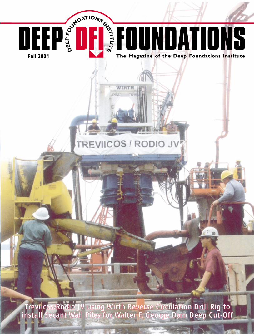
Fall 2004
TTrreevviiiiccooss//RRooddiioo JJVV uussiinngg WWiirrtthh RReevveerrssee CCiirrccuullaattiioonn DDrriillll RRiigg ttoo iinnssttaallll SSeeccaanntt WWaallll PPiilleess ffoorr WWaalltteerr FF.. GGeeoorrggee DDaamm DDeeeepp CCuutt--OOffff
DEEP FOUNDATIONS Fall 2004
Deep FoundationsInstitute326 Lafayette AvenueHawthorne, NJ07506973.423.4030FAX 973.423.4031
80
PRESORTED STANDARDU.S. POSTAGE PAID
FOLCROFT, PAPERMIT NO. 100
Flotilla of Equipment used by Treviicos/Rodio JV to installDeep Cut-Off at Walter F. George Dam. Powerhouse and Spillway
Flotilla of Equipment used by Treviicos/Rodio JV to installDeep Cut-Off at Walter F. George Dam. Powerhouse and Spillway
DFI "fall" qxd./04 1/1/04 3:20 AM Page 1

Fall 2004 DEEP FOUNDATIONS 5DEEP FOUNDATIONS Fall 200476
The Deep Cut-Off at the Walter F. George Dam
By Arturo Ressi di Cervia, President, TREVIICOS Corporation, Boston, MA, USA
INTRODUCTION
The Walter F. George lock and dam was constructedon the Chattahoochee River between 1955 and 1963 withthe double function of improving navigation andgenerating power. Its 82 ft. by 450 ft. (25m x 137m) lockcan accommodate large barge traffic and its fourgenerating units with a plant capacity of 150 MW have anaverage energy output of 453,000 MWH. The dam consistsof a 1,496 ft. (456m) long concrete structure housing thespillway, a non overflow portion, the power units and twoearthen wing dams extending to the Georgia and Alabamasides, respectively 5,810 feet and 6,130 feet long (1770mand 1868m).
As soon as the reservoir was impounded it becameapparent that excessive seepage was occurring. From 1962to 1985 a series of remedial works was performed usingseveral techniques, but the problems continued under thedam, jeopardizing its generating potential and possiblyundermining its stability.
Finally, the decision was made to construct a deep cut-off primarily under the concrete portion of the dam toremedy the problem.
PROCUREMENT
On July 5th, 2001 best and final offers were solicitedby the Corps of Engineers (COE) for the construction of adeep cut-off to be built in front of the concrete portion ofthe dam from the bottom of the lake and tied into it. Thecut-off had to cross an existing lock structure and anunderwater retaining wall, as well as the remnants of asteel coffer cell left in place from the initial construction.
The specifications required that the wall be built with aminimum thickness of 24” (600mm) and that it extendedfrom the bottom of the lake to elevation -5 (1.52m) into theProvidence formation, an impervious layer.
While the land portions of the wall were on average208 feet (63.4m) deep, the marine portion started from upto 90 feet (27m) of water and continued through differentrock formations for another 100 feet (30m).
Contractors were invited to propose their own methodof constructing the cut-off and offers would be evaluatedusing several criteria, including technical, economical,organizational and experience.
Three proposals were received and on August 14, 2001an award was made to the Joint Venture (JV) of Treviicosand Rodio.
THIS PROJECT RECEIVED THE DFI OUTSTANDING PROJECT AWARDFOR 2004
Aerial View of Cut-Off Wall Construction
Plan View of the Cut-Off Wall
THIS PROJECT RECEIVED THE DFI OUTSTANDING PROJECT AWARDFOR 2004
By Arturo Ressi di Cervia, President, TREVIICOS Corporation, Boston, MA, USA
INTRODUCTION
PROCUREMENTConverse Consultants3 Century Drive
Parsippany, New Jersey 07054(973) 605-5200
Specialized Services for the Pile Construction Industry
- Pile Driving Analyzer (PDA) Testing- Value Engineering- Geotechnical Reports- Construction Inspection & Management- Construction Services for Deep Foundations- Quality Control/ Quality Assurance for Driven & Drilled Piles
Converse ConsultantsOver 50 years in Geotechnial Engineering and Environmental Services
Pile Driving Analyzer
Plan view of the Cut-Off Wall
DFI "fall" qxd./04 1/1/04 3:20 AM Page 9

Fall 2004 DEEP FOUNDATIONS 75DEEP FOUNDATIONS Fall 20046
JV’S PROPOSED CONSTRUCTION METHOD
Treviicos-Rodio proposed to do the marine portion ofthe work with secant piles, using water as drilling fluid,while the land portion would be a slurry wall done byhydromill, using bentonite as a stabilizing fluid.
The proposal contemplated a preliminary drilling andgrouting campaign in order to verify ground conditionsand to fill any large voids which could disrupt the orderlyprogress of the work.
After the completion of the drilling and grouting, thework would be performed in a series of operations asfollows:
1 . Cleaning the Lake Bottom and Constructing aWorking Apron
The purpose of the apron installation was to create azone, upstream of the dam monolith, free of obstructionand consisting of solid, homogeneous material forming theworking surface used to install the cutoff wall and,ultimately, the cap beam connecting the cut-off to the dam.
2. Installing Casing Templates Tied to the ConcreteDam
Whenever possible, guide beams and templates wereinstalled and secured to the concrete dam structures. Themain beam was mounted on the props fixed to the fendersof the dam. Its position and alignment was checked usingreference points previously installed on the dam during theinitial survey.
When it was impossible to attach the template to thedam, temporary piles were driven to support the original ora modified template. The templates were used to installand drive the temporary casing into the apron.
3. Drilling and Concreting Piles
The primary tool used to construct the secant pilediaphragm wall was a WIRTH PBA 612 ReverseCirculation Drill Rig. The 50-inch (1270mm) secant piles,spaced 33 inches (838mm) center to center, formed thecut-off wall. The piles were installed in a sequence ofprimaries and secondaries, in which the secondary pileswere drilled between the two adjacent primary piles.
The piles were installed to form a continuous wall, ofthe minimum thickness of 24 inches (600mm), from thelakebed to El –5 MSL (–1.52m), into the Providenceformation.
Phase I - Primary Piles Installation
Phase II – Secondary Piles Installation
4. Constructing the Slurry Wall
The slurry wall was built by primary and secondarypanels using a Soletanche H12000 series Hydromill. The primary panel was formed by single or multiplebites with a total excavation length of 8 to 24 feet (2.4 to7.3m). The secondary panels overlapping the primarieswere a single 8-foot (2.4m) bite.
The de-sanding plant was a Sotres-450 consisting of aseries of vibrating screens and cyclones capable ofscreening all the cutting sizes with a capacity of 500 cu.yd. (382 m3) per hour.
5 . Constructing the Cut-Off Through the LockStructure
The crossing of the lock structure was accomplishedby using a combination of Hydromill and secant piletechniques.
Templates
JV’S PROPOSED CONSTRUCTION METHOD
www.ConstructionWebLinks.comWebsite of Thelen Reid & Priest LLP
Through e-mails received on the subject “ConstructionBusiness Bulletin”, we have become aware of this interestingwebsite, which features links to numerous organizations, andcontains useful current news items and information on con-struction, business, safety and legal topics, plus useful tools,project databases, a construction calendar, business bulletinsand a construction bulletin board, to which readers can postitems.
The website is a service of Thelen Reid & Priest LLP, a lawfirm with extensive experience in construction industry issues.The site is readily searchable.
We recommend this site as “Worth a Good Look.”
DFI "fall" qxd./04 1/1/04 3:20 AM Page 11

Fall 2004 DEEP FOUNDATIONS 7DEEP FOUNDATIONS Fall 200474
Section of the Slurry WallSection of the Secant Pile Wall
WIRTH Reverse Circulation Rig
Hydromill and Guide Pipes
Hydromill
DFI "fall" qxd./04 1/1/04 3:20 AM Page 13

Fall 2004 DEEP FOUNDATIONS 73DEEP FOUNDATIONS Fall 20048
6. Constructing the Permanent Concrete Cap Tyingthe Cut-Off to the Dam
The construction of the cap beam was done uponcompletion of the cut-off installation. Depending on thecut-off wall’s position and the apron elevation, a portion,or all, of the engineered backfilling between the cut-offwall and the dam was removed in order to install the capbeam.
Before pouring the 3000 p.s.i. (20 Mpa) concrete ofthe cap beam, the surfaces of the monoliths and of the cut-off wall were cleaned to insure a proper joint.
CHANGES
It is inevitable that in a job of such complexity,situations will arise requiring changes in the original scopeof work. In some cases they are caused by changedconditions, in others by value engineering proposals, whilein some other cases they involve additional work.
This contract had examples of all three cases, and thechallenge was to integrate those changes in the schedule inorder to minimize their impact in terms of both cost andtime.
This can be best accomplished if the need for thosechanges is recognized, evaluated and contractuallyresolved in a timely fashion; in this respect an effective“partnering” atmosphere is critical in moving the processalong.
We can proudly say that both the Corps and the JVworked hard to make partnering a reality on this project,and that, as a result, all necessary changes were dealt withexpeditiously and in a mutually satisfactory manner.
The partnering and cooperation effort was used notonly to overcome the unexpected but also to developalternate solutions with associated savings for all partiesinvolved. This was the case in the Value EngineeringProposal for the open water disposal. The VECP proposedthe modification of the contract for the disposal of the50,000 c.y. (38,000 m3) of combined dredge and drillspoil. The open water disposal was selected in lieu of anup-land facility, resulting in substantial savings sharedbetween the JV and the COE.
LESSONS LEARNED
• Pre Bid Preparation
By assembling a large team of experts the JV was ableto explore different technical solutions, compare them bycost and reliability and consequently hone into the bestpossible approach. This exhaustive preliminary work hadthe additional benefit of comforting the JV that it had theright price when it became known that our competitor’s
proposals were considerably higher. Since the job wasperformed in line with the JV’s expectations andcompleted six months ahead of schedule, it proved that, indesign-build contracts, wide swings in prices reflectdifferent solutions to the problem, not mistakes or greed.
• Preliminary Investigation
By conducting the exploratory campaign previouslydescribed, the JV gained vital information, which allowedit to plan the work ahead, even when confronted withsituations at variance from what the contract documents,showed. It reinforces the truism that advance informationis relatively cheap to acquire and it pays for itself manytimes over in avoiding or mitigating delays and extra costsduring the performance of the work.
• Partnering
Much has been said about it that does not needrepeating; it must be stressed, though, that partnering isboth an attitude and a commitment and that it needs to becontinuously reinforced. On this project both the Corpsand the contractor committed themselves to make it work.It directly facilitated the resolution of the various issuescaused by changed conditions, contract modifications andvalue engineering proposals by staging negotiations in anatmosphere of mutual trust and respect.
• Project monitoring
By the creation of a management committee drawnfrom the partners and by appointing an executive incharge, the JV was able to follow closely the progress ofthe job and to marshal quickly additional resources andexpertise when required. This allowed for timelyevaluation, study and implementation of procedures atvariance from what was anticipated in the originalproposal.
CONCLUSIONS
The construction of a deep underwater cut-off hadnever been attempted before and its successful completionwill open new possibilities to Engineers and Owners onhow to deal with difficult underwater seepage problems.
Although the completion ahead of schedule and underbudget of a job of this difficulty and magnitude is aremarkable feat, the project team’s greatest and proudestachievement consists in the fact that “the project,performed during a six day work week, operating 24hours a day, was successfully completed without a lost-time accident” as stated in Resolution 53 EX, introducedby the Honorable Gerald Greene and adopted May 6th,2004 by the United States’ House of Representatives.
CHANGES
CONCLUSIONS
LESSONS LEARNED
Before pouring the 3000 p.s.i. (20 Mpa) concrete of thecap beam, the surfaces of the monoliths and of the cut-offwall were cleaned to insure a proper joint.
DFI "fall" qxd./04 1/1/04 3:21 AM Page 15

Fall 2004
TTrreevviiiiccooss//RRooddiioo JJVV uussiinngg WWiirrtthh RReevveerrssee CCiirrccuullaattiioonn DDrriillll RRiigg ttoo iinnssttaallll SSeeccaanntt WWaallll PPiilleess ffoorr WWaalltteerr FF.. GGeeoorrggee DDaamm DDeeeepp CCuutt--OOffff
DEEP FOUNDATIONS Fall 2004
Deep FoundationsInstitute326 Lafayette AvenueHawthorne, NJ07506973.423.4030FAX 973.423.4031
80
PRESORTED STANDARDU.S. POSTAGE PAID
FOLCROFT, PAPERMIT NO. 100
Flotilla of Equipment used by Treviicos/Rodio JV to installDeep Cut-Off at Walter F. George Dam. Powerhouse and Spillway
Flotilla of Equipment used by Treviicos/Rodio JV to installDeep Cut-Off at Walter F. George Dam. Powerhouse and Spillway
DFI "fall" qxd./04 1/1/04 3:20 AM Page 1