Embed Size (px)
Citation preview
IN BETWEEN: DESIGNING JOINTS WITHIN FAÇADES
MINJUNG MAING, PE, LEED AP, ASSOC. AIA SIMPSON GUMPERTZ & HEGER INC.
1055 W. 7th Street, Suite 2500, Los Angeles, CA 90017
Phone: 213-271-1919 • Fax: 213-617-0411 • E-mail: [email protected]
S Y M P O S I U M O N B U I L D I N G E N V E L O P E T E C H N O L O G Y • N O V E M B E R 2 0 1 0 M A I N G • 7 3
ABSTRACT
How the façade elements join with the adjoining materials, assemblies, and systems should be considered early in the design phase. Left to the end, the joinery of the building systems creates abrupt conditions at terminations, transitions, and corners. This can, in turn, lead to building covers that do not address issues of thermal performance of materials, weather protection (including air infiltration and water penetration), fire resistance, and plumbing systems of the building. Although there are general guidelines for designing smaller joints such as sealantjoint performance parameters, wider joints such as expansion and seismic joints are underrepresented, creating delays and confusion during construction.
This paper will discuss how to detail the different types of joints, using case studies and examples of joints that were nonconforming and that were redesigned to comply with performance criteria. The principles presented are relevant to design and construction teams and researchers. It is critical that these joints be considered for the climactic conditions that façade assemblies are meant to address in order to design a holistic façade system with the desired performance requirements.
SPEAKER
MINJUNG MAING, PE, LEED AP, ASSOC. AIA — SIMPSON GUMPERTZ & HEGER INC.
Minjung Maing, PE, LEED AP, Assoc. AIA, is a senior staff editor with Simpson Gumpertz & Heger, Inc., and an assistant professor with the Georgia Institute of Technology School of Architecture. She has ten years of industry experience ranging from architecture and structural engineering to building technology. Her focus is on building envelope performance and integration of design, testing, and construction processes toward a holistic design approach. She has been involved in various remedial design and newconstruction projects, including custom design of curtain walls, windows, roofing, wall cladding systems as precast panels, EIFS, cement plaster, brick and stone veneer, metal panels, and plaza and belowgrade waterproofing. She received dual bachelor’s degrees in architecture and engineering from the University of Pennsylvania and an MS in civil/structural engineering from Stanford University as well as a professional master’s degree in architecture from the Massachusetts Institute of Technology (MIT). She is a registered professional engineer in California and currently teaches at Georgia Institute of Technology in the School of Architecture.
7 4 • M A I N G S Y M P O S I U M O N B U I L D I N G E N V E L O P E T E C H N O L O G Y • N O V E M B E R 2 0 1 0
IN BETWEEN: DESIGNING JOINTS WITHIN FAÇADES
Designing a façade—also referred to as a building envelope system—while maintaining desired aesthetics and avoiding performance problems, requires attention to materials and process of assembly. Materials—their installation, physical properties, and compatibility issues—should be carefully considered and clearly detailed to include the design of joints that subsequently affect building performance. Joinery of façade components is often assumed by the designer and not closely examined until the later stages of construction documents and sometimes not thoroughly discussed until installation on the project. Joints within the façade are relatively small elements and account for a small percentage of the wall system and entire building envelope. However, if the subject joints are not designed properly, they become points of moisture intrusion that create problems with air, moisture, and thermal energy leakage. Since these elements travel along paths of least resistance, these breaches in the façade will significantly affect the building envelope performance and, inevitably, the building as a whole. To describe joints, their functions, design options, and problems associated with poor details, this paper is presented in the following sections:
1. Role of joints 2. Types of vertical joints 3. How joints are typically designed and
common problems that arise from the choice of joint infill material
4. Design principles for a better performing joint system
5. Conclusion
ROLE OF JOINTS Joints are prevalent in many applica
tions and play a critical role in the function of the façade cladding components. The human body is an example in which joints between our bones allow us to move and give each limb a function within a coordinated structure. Joints between our body organs that are different from bone joints have specific functions, such as opening and closing, allowing us to breathe and live.
In buildings, there are several types of joints of differing scales and functions; however, façade joints can be categorized into three main types, excluding façade structural attachment joints.
• Control joints • Expansion joints • Lateral drift (seismic) joints
Although there are three types, a joint within a façade can consist of a hybrid, such as a seismic expansion joint that is designed to address lateral drift of the building and material expansion and contraction. All joints should be designed to handle the expansive and contractive properties of the wallcladding materials within and adjacent to the joints due to the effects of the environment on structural and nonstructural components. For the purpose of this discussion, focus will be given to the latter two types of joints—expansion and lateral joints—which are prominent inclusions within prefabricated façade components/unit assemblies.
Better understanding and representation through threedimensional isometric details are essential for the design team to ensure a consistent level of performance across the joint, as with the building façade. To accentuate the importance of joint design, there are some instances where a joint subcontractor who is responsible for installing all the joint material within the façade is hired—particularly where there are several different types of façade materials, and manufacturer/installers are reluctant to install joint material to connect their systems to other manufacturer systems. The design team then decides that having one subcontracting entity to install sealant joints throughout the project will result in better quality and liability control. The conditions that arise from this arrangement are thorough details of joints in the various project conditions, coordination among trades to ensure proper sequencing, testing of assemblies to assure proper installation of joint and façade materials, and integration with adjacent wall systems.
TYPES OF VERTICAL JOINTS Expansion Joints
Expansion joints are introduced to accommodate building movements caused by temperature changes: expansion; contraction; and, in some instances, moisture; and (particularly when designing with concrete) creep. Although control joints will not be discussed in depth in this paper, the following description is important to differentiate them from expansion joints. Control joints occur within façade systems, and their main function is to break up the façade surface to control the shrinkage tensile stresses within the cladding material which cause excessive cracking if not alleviated. They are commonly found in cementitiousbased wall cladding systems, such as cement plaster, concrete masonry, and concrete, and run as deep as the cladding system or, in the example of concrete, 25% of the depth of the concrete wall. Section 3 of ASTM C1063 states that a control joint “accommodates movement of plaster shrinkage and curing along predetermined, usually straight lines.” The key word being “predetermined,” therefore controlling where the designer will be able to tolerate cracks or lines where controljoint accessories will exist within their façades.
Expansion joints are often oneway joints, primarily intended to accommodate movements in the direction perpendicular to the joint, and are commonly placed at regular intervals of length, based on the expected rate of expansion and contraction over the building length. They are similar to control joints in that they are required at regular intervals due to the linear coefficient of thermal expansion of materials [as calculated by ∆(ft) = 0.0000065*L(ft)*∆T(°F)] and yet differ from control joints, in that whereas the expansion of the framing and structure are being accounted for they penetrate through the entire wall section and not just the cladding system. All materials expand and contract when exposed to temperature differentials; therefore, expansion joints should take into account expansion of the structure as well as the façadecladding materials.
S Y M P O S I U M O N B U I L D I N G E N V E L O P E T E C H N O L O G Y • N O V E M B E R 2 0 1 0 M A I N G • 7 5
A B
C
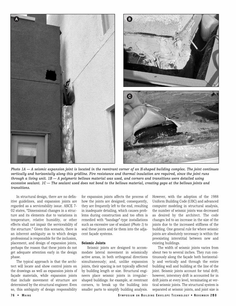
Photo 1A — A seismic expansion joint is located in the reentrant corner of an Hshaped building complex. The joint continues vertically and horizontally along this gridline. Fire resistance and thermal insulation are required, since the joint runs through a living unit. 1B — A polymeric bellows material was used, and corners and transitions were detailed using excessive sealant. 1C — The sealant used does not bond to the bellows material, creating gaps at the bellows joints and transitions.
In structural design, there are no definitive guidelines, and expansion joints are regarded as a serviceability issue. ASCE 702 states, “Dimensional changes in a structure and its elements due to variations in temperature, relative humidity, or other effects shall not impair the serviceability of the structure.” Given this scenario, there is an inherent ambiguity as to which design professional is responsible for the inclusion, placement, and design of expansion joints, perhaps the reason that these joints do not get adequate attention early in the design phase.
The typical approach is that the architect will locate and show control joints on the drawings as well as expansion joints of façade materials, while expansion joints that include movement of structure are determined by the structural engineer. Even so, this ambiguity of design responsibility
for expansion joints affects the process of how the joints are designed; consequently, they are frequently left to the end, resulting in inadequate detailing, which causes problems during construction and too often is remedied with “bandage”type installations such as excessive use of sealant (Photo 1) to seal these joints and tie them into the adjacent façade systems.
Seismic Joints Seismic joints are designed to accom
modate lateral movement in seismically active areas, in both orthogonal directions simultaneously; and, unlike expansion joints, their spacing is not typically affected by building length or size. Structural engineers place seismic joints in irregularshaped buildings: for example, at reentrant corners, to break up the building into smaller parts to simplify building analysis.
However, with the adoption of the 1988 Uniform Building Code (UBC) and advanced computer modeling in structural analysis, the number of seismic joints was decreased as desired by the architect. The code changes led to an increase in the size of the joints due to the increased stiffness of the building. One general rule for where seismic joints are absolutely necessary is within the preexisting interstitial between new and existing buildings.
The width of seismic joints varies from about two to several inches. They run continuously along the façade both horizontally and vertically and through the entire building wall and building at the line of the joint. Seismic joints account for total drift; however, interstory drift is accounted for in drift joints at every level, terminating at vertical seismic joints. The structural system is separated at seismic joints, and joint size is
7 6 • M A I N G S Y M P O S I U M O N B U I L D I N G E N V E L O P E T E C H N O L O G Y • N O V E M B E R 2 0 1 0
generally the sum of story drift of the two isolated building sections adjacent to the joint. Special structural and architectural detailing are required to maintain the separation while, in some cases, creating a continuous building façade to cover these joints. Designers tend to turn to prefabricated joint cover assemblies that do not take into account building aesthetics and custom conditions, in some cases leaving designers unhappy at the strikingly obvious mark left on the building exterior.
HOW JOINTS ARE TYPICALLY DESIGNED AND COMMON PROBLEMS THAT ARISE FROM THE CHOICE OF JOINT INFILL MATERIAL
In current construction, most expansion and seismic joints are designed and sealed using either sealant materials (liquid or impregnated foam sealant), or preformed jointcover assemblies. The choice of joint material is based on the size of the joint; generally, designers tend to turn to liquid sealant where applicable and revert to preformed joint covers for larger joints when liquid sealant is no longer an option.
Liquid Sealant and Foam Joints
Sealant joint materials come either in liquid form or solidstate impregnated foam. Liquid sealants, due to their limitation in application, are commonly used to span across small joints (generally ¼ to 1 in), seal laps, and butt the joints of materials. However, for larger joints, which can be considered 2 in or wider, sealant can be considered inappropriate due to installation issues, as discussed below. Sealant compounds vary and should be carefully reviewed to understand their limitations. Dow Corning, in its technical manual, recommends that its silicone sealants be used for joints that range from ¼ in to a maximum of 4 in
S Y M P O S I U M O N B U I L D I N G
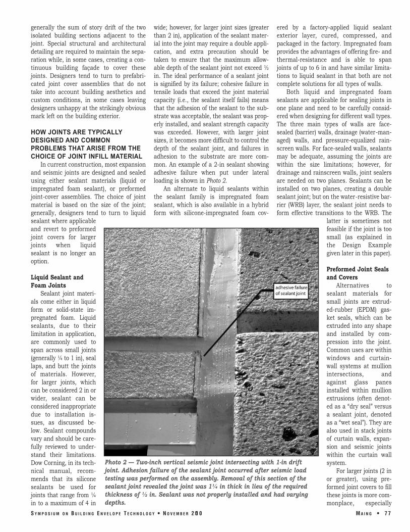
wide; however, for larger joint sizes (greater than 2 in), application of the sealant material into the joint may require a double application, and extra precaution should be taken to ensure that the maximum allowable depth of the sealant joint not exceed ½ in. The ideal performance of a sealant joint is signified by its failure; cohesive failure in tensile loads that exceed the joint material capacity (i.e., the sealant itself fails) means that the adhesion of the sealant to the substrate was acceptable, the sealant was properly installed, and sealant strength capacity was exceeded. However, with larger joint sizes, it becomes more difficult to control the depth of the sealant joint, and failures in adhesion to the substrate are more common. An example of a 2in sealant showing adhesive failure when put under lateral loading is shown in Photo 2.
An alternate to liquid sealants within the sealant family is impregnated foam sealant, which is also available in a hybrid form with siliconeimpregnated foam cov
Photo 2 — Twoinch vertical seismic joint intersecting with 1in drift joint. Adhesion failure of the sealant joint occurred after seismic load testing was performed on the assembly. Removal of this section of the sealant joint revealed the joint was 1¼ in thick in lieu of the required thickness of ½ in. Sealant was not properly installed and had varying depths.
E N V E L O P E T E C H N O L O G Y • N O V E M B E R 2 0 1 0
ered by a factoryapplied liquid sealant exterior layer, cured, compressed, and packaged in the factory. Impregnated foam provides the advantages of offering fire and thermalresistance and is able to span joints of up to 6 in and have similar limitations to liquid sealant in that both are not complete solutions for all types of walls.
Both liquid and impregnated foam sealants are applicable for sealing joints in one plane and need to be carefully considered when designing for different wall types. The three main types of walls are facesealed (barrier) walls, drainage (watermanaged) walls, and pressureequalized rainscreen walls. For facesealed walls, sealants may be adequate, assuming the joints are within the size limitations; however, for drainage and rainscreen walls, joint sealers are needed on two planes. Sealants can be installed on two planes, creating a double sealant joint; but on the waterresistive barrier (WRB) layer, the sealant joint needs to form effective transitions to the WRB. The
latter is sometimes not feasible if the joint is too small (as explained in the Design Example given later in this paper).
Preformed Joint Seals and Covers
Alternatives to sealant materials for small joints are extrudedrubber (EPDM) gasket seals, which can be extruded into any shape and installed by compression into the joint. Common uses are within windows and curtainwall systems at mullion intersections, and against glass panes installed within mullion extrusions (often denoted as a “dry seal” versus a sealant joint, denoted as a “wet seal”). They are also used in stack joints of curtain walls, expansion and seismic joints within the curtain wall system.
For larger joints (2 in or greater), using preformed joint covers to fill these joints is more commonplace, especially
M A I N G • 7 7
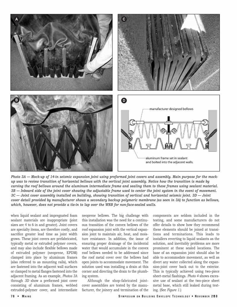
when liquid sealant and impregnated foam sealant materials are inappropriate (joint sizes are 4 to 6 in and greater). Joint covers are specialty items, are therefore costly, and sacrifice greater lead time as joint width grows. These joint covers are prefabricated, typically metal or extruded polymer covers, and may also include flexible bellows made of extruded polymer (neoprene, EPDM) clamped into place by aluminum frames (also referred to as mounting rails), which are fastened into the adjacent wall surfaces or clamped to metal flanges fastened into the adjacent framing. As an example, Photos 3A through 3D show a preformed joint cover consisting of aluminum frames, webbed extrudedpolymer cover, and intermediate
neoprene bellows. The big challenge with this installation was the need for a continuous transition of the convex bellows of the roof expansion joint with the vertical expansion joint to maintain air, heat, and moisture resistance. In addition, the issue of ensuring proper drainage of the incidental water that would accumulate in the convex roof bellows needed to be addressed since the roof metal cover over the bellows had open joints to accommodate movement. The solution used was installing a drain at this corner and directing the drain to the plumbing system.
Although the shopfabricated jointcover assemblies are tested by the manufacturer, the joinery and termination of the
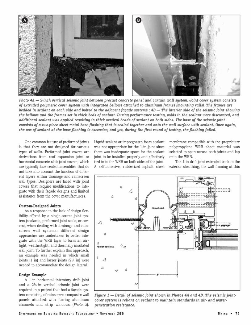
components are seldom included in the testing, and some manufacturers do not offer details to show how they recommend these elements should be joined at transitions and terminations. This leads to installers reverting to liquid sealants as the solution, and inevitably problems are more prominent at these sealed locations. The base of an expansion joint should also be able to accommodate movement, as well as divert any water collected along the expansionjoint cover back out to the exterior. This is typically achieved using twopiece sheetmetal flashings. Photo 4 shows excessive use of sealant at the twopiece sheet metal base, which still leaked during testing. (See Figure 1.)
7 8 • M A I N G S Y M P O S I U M O N B U I L D I N G E N V E L O P E T E C H N O L O G Y • N O V E M B E R 2 0 1 0
A C
DB
Photo 3A — Mockup of 14in seismic expansion joint using preformed joint covers and assembly. Main purpose for the mockup was to review transition of horizontal bellows with the vertical joint assembly. Notice how the transition is made by carving the roof bellows around the aluminum intermediate frame and sealing them to these frames using sealant material. 3B — Inboard side of the joint cover showing the adjustable frame used to center the joint system in the event of movement. 3C — Joint cover assembly installed on building, showing transition of vertical and horizontal seismic joint. 3D — Joint cover detail provided by manufacturer shows a secondary backup polymeric membrane (as seen in 3A) to function as bellows, which, however, does not provide a tiein to lap over the WRB for nonfacesealed walls.
A B
Photo 4A — 2inch vertical seismic joint between precast concrete panel and curtain wall system. Joint cover system consists of extruded polymeric cover system with integrated bellows attached to aluminum frames (mounting rails). The frames are bedded in sealant on each side and bolted to the adjacent façade systems.; 4B — The interior side of the seismic joint showing the bellows and the frames set in thick beds of sealant. During performance testing, voids in the sealant were discovered, and additional sealant was applied resulting in thick vertical beads of sealant on both sides. The base of the seismic joint consists of a twopiece sheet metal base flashing that is sealed together and onto the wall surface with sealant. Once again, the use of sealant at the base flashing is excessive; and yet, during the first round of testing, the flashing failed.
One common feature of preformed joints Liquid sealant or impregnated foam sealant membrane compatible with the proprietary is that they are not designed for various was not appropriate for the 1in joint since polypropylene WRB sheet material was types of walls. Preformed joint covers are there was inadequate space for the sealant selected to span across both joints and lap derivations from roof expansion joint or joint to be installed properly and effectively onto the WRB. horizontal concreteslab joint covers, which tied in to the WRB on both sides of the joint. The 1in drift joint extended back to the are typically facesealed assemblies that do A selfadhesive, rubberizedasphalt sheet exterior sheathing; the wall framing at this not take into account the function of different layers within drainage and rainscreen wall types. Designers are faced with joint covers that require modifications to integrate with their façade designs and limited assistance from the cover manufacturers.
Custom-Designed Joints As a response to the lack of design flex
ibility offered by a singlesource joint system (sealants, preformed joint seals, or covers), when dealing with drainage and rainscreen wall systems, different design approaches are undertaken to better integrate with the WRB layer to form an airtight, weathertight, and thermally insulated wall joint. To further explain this approach, an example was needed in which small joints (1 in) and larger joints (2¼ in) were needed to accommodate the design lateral.
Design Example A 1in horizontal interstory drift joint
and a 2¼in vertical seismic joint were required in a project that had a façade system consisting of rainscreen composite wall panels attached with furring aluminum channels and strip windows (Photo 5).
Figure 1 — Detail of seismic joint shown in Photos 4A and 4B. The seismic jointcover system is reliant on sealant to maintain standards in air and waterpenetration resistance.
S Y M P O S I U M O N B U I L D I N G E N V E L O P E T E C H N O L O G Y • N O V E M B E R 2 0 1 0 M A I N G • 7 9
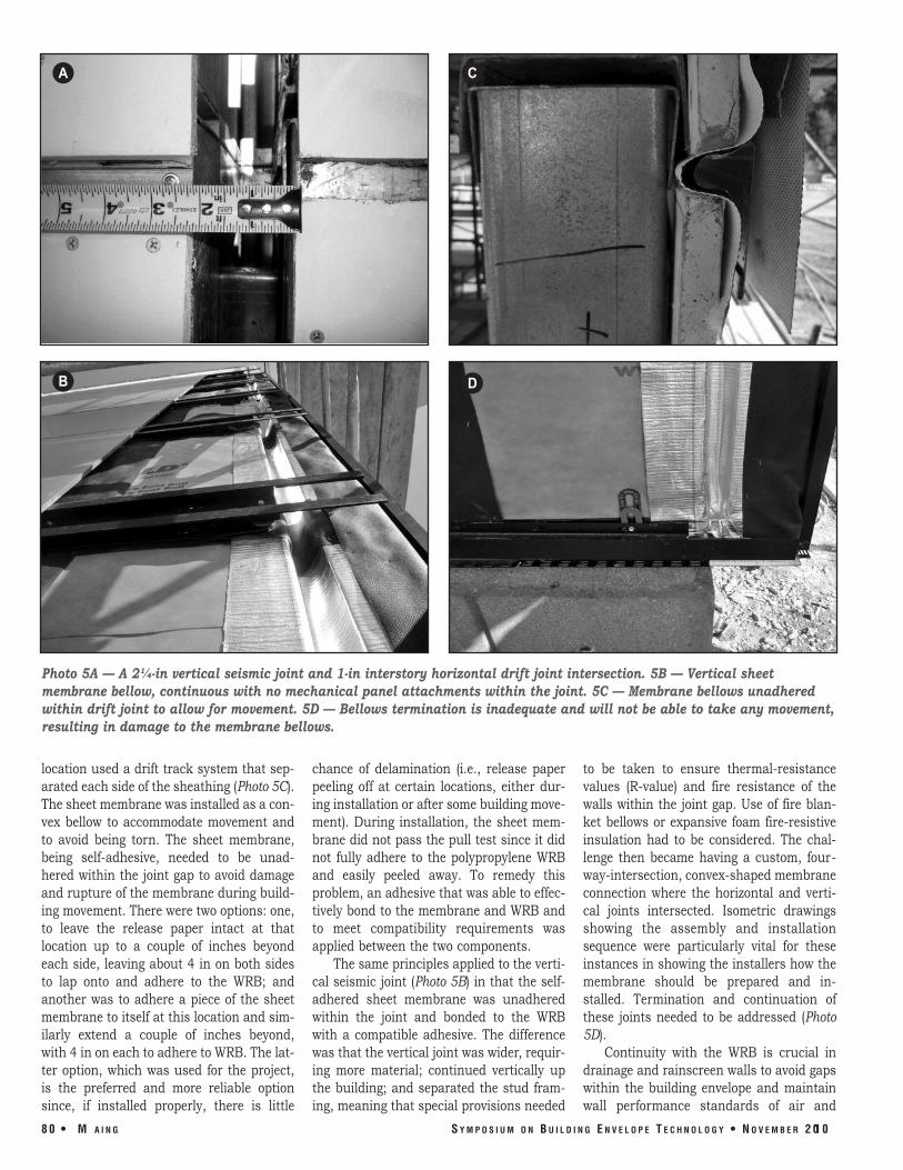
location used a drift track system that separated each side of the sheathing (Photo 5C). The sheet membrane was installed as a convex bellow to accommodate movement and to avoid being torn. The sheet membrane, being selfadhesive, needed to be unadhered within the joint gap to avoid damage and rupture of the membrane during building movement. There were two options: one, to leave the release paper intact at that location up to a couple of inches beyond each side, leaving about 4 in on both sides to lap onto and adhere to the WRB; and another was to adhere a piece of the sheet membrane to itself at this location and similarly extend a couple of inches beyond, with 4 in on each to adhere to WRB. The latter option, which was used for the project, is the preferred and more reliable option since, if installed properly, there is little
chance of delamination (i.e., release paper peeling off at certain locations, either during installation or after some building movement). During installation, the sheet membrane did not pass the pull test since it did not fully adhere to the polypropylene WRB and easily peeled away. To remedy this problem, an adhesive that was able to effectively bond to the membrane and WRB and to meet compatibility requirements was applied between the two components.
The same principles applied to the vertical seismic joint (Photo 5B) in that the selfadhered sheet membrane was unadhered within the joint and bonded to the WRB with a compatible adhesive. The difference was that the vertical joint was wider, requiring more material; continued vertically up the building; and separated the stud framing, meaning that special provisions needed
to be taken to ensure thermalresistance values (Rvalue) and fire resistance of the walls within the joint gap. Use of fire blanket bellows or expansive foam fireresistive insulation had to be considered. The challenge then became having a custom, fourwayintersection, convexshaped membrane connection where the horizontal and vertical joints intersected. Isometric drawings showing the assembly and installation sequence were particularly vital for these instances in showing the installers how the membrane should be prepared and installed. Termination and continuation of these joints needed to be addressed (Photo 5D).
Continuity with the WRB is crucial in drainage and rainscreen walls to avoid gaps within the building envelope and maintain wall performance standards of air and
8 0 • M A I N G S Y M P O S I U M O N B U I L D I N G E N V E L O P E T E C H N O L O G Y • N O V E M B E R 2 0 1 0
A C
DB
Photo 5A — A 2¼in vertical seismic joint and 1in interstory horizontal drift joint intersection. 5B — Vertical sheet membrane bellow, continuous with no mechanical panel attachments within the joint. 5C — Membrane bellows unadhered within drift joint to allow for movement. 5D — Bellows termination is inadequate and will not be able to take any movement, resulting in damage to the membrane bellows.
moisture penetration and thermal insulation. Figures 2 and 3 are custom joint details for drainage and rainscreen façades with similar design strategies used in the design example. The two details show how sealants—both liquid and foam types—can be used in conjunction with other materials such as selfadhesive sheet membrane bellows.
The advantages to using customdesigned joints are that it gives the design team more control, requires better understanding of the function of the materials within and surrounding the joint, and makes manufacturers aware of the necessary tiein of the joint system to the adjacent materials. It does not eliminate the need for the preformed joint covers or sealants but, instead, allows the designer to use a combination of different materials and prefabricated covers that are compatible and form a wellsealed performing joint. For drainagewall systems, installations of membrane bellows similar to the design example can be used; however, an outer seal (Figure 2) or flashing should be introduced to cover the joint to maintain the primary, outer weatherprotection surface. For rainscreen façade systems, the attachments should be clear of the expansion and seismic joints, and the panel joints can be left open as in Photo 5B or sealed as in Figure 3.
DESIGN PRINCIPLES FOR A BETTERPERFORMING JOINT SYSTEM
To avoid costly problems resulting from inadequate joint design, insufficient detailing, and poor coordination when installing expansion and seismicjoint infill and covers, the following design principles should be considered:
1. Determine where joints occur throughout the building and façade (e.g., where an addition meets the original building, irregular building corners, material changes, etc.). Once façade materials are selected, designers should consult with the manufacturer for information on minimum expansion joint sizes and intervals, both vertically and horizontally, based on performance testing results, a successful track record, and material properties. It is important to note that seismic and some expansion joints are continuous in that vertical joints will join with horizontal and roof expansion joints.
2. Review the joint sizes required and
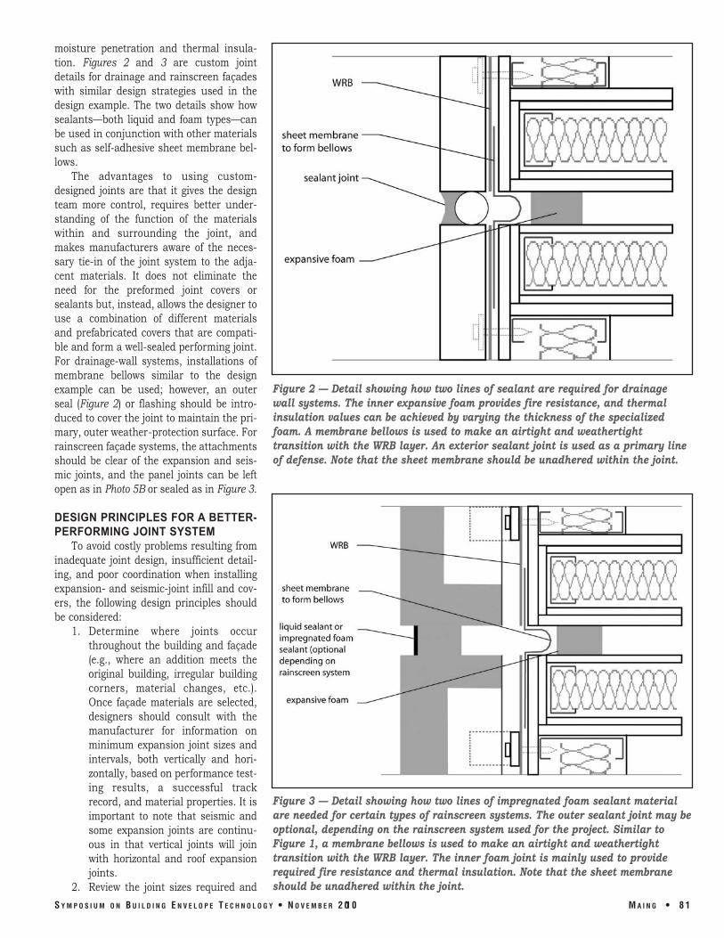
Figure 2 — Detail showing how two lines of sealant are required for drainage wall systems. The inner expansive foam provides fire resistance, and thermal insulation values can be achieved by varying the thickness of the specialized foam. A membrane bellows is used to make an airtight and weathertight transition with the WRB layer. An exterior sealant joint is used as a primary line of defense. Note that the sheet membrane should be unadhered within the joint.
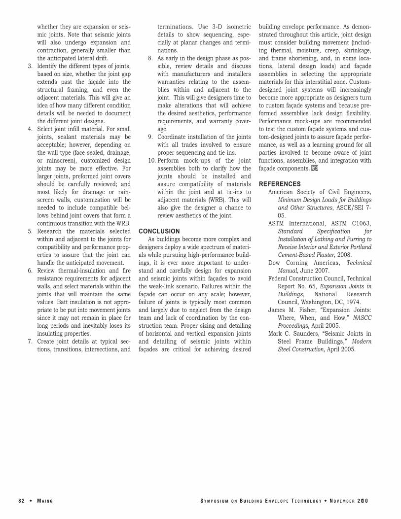
Figure 3 — Detail showing how two lines of impregnated foam sealant material are needed for certain types of rainscreen systems. The outer sealant joint may be optional, depending on the rainscreen system used for the project. Similar to Figure 1, a membrane bellows is used to make an airtight and weathertight transition with the WRB layer. The inner foam joint is mainly used to provide required fire resistance and thermal insulation. Note that the sheet membrane should be unadhered within the joint.
S Y M P O S I U M O N B U I L D I N G E N V E L O P E T E C H N O L O G Y • N O V E M B E R 2 0 1 0 M A I N G • 8 1
whether they are expansion or seismic joints. Note that seismic joints will also undergo expansion and contraction, generally smaller than the anticipated lateral drift.
3. Identify the different types of joints, based on size, whether the joint gap extends past the façade into the structural framing, and even the adjacent materials. This will give an idea of how many different condition details will be needed to document the different joint designs.
4. Select joint infill material. For small joints, sealant materials may be acceptable; however, depending on the wall type (facesealed, drainage, or rainscreen), customized design joints may be more effective. For larger joints, preformed joint covers should be carefully reviewed; and most likely for drainage or rainscreen walls, customization will be needed to include compatible bellows behind joint covers that form a continuous transition with the WRB.
5. Research the materials selected within and adjacent to the joints for compatibility and performance properties to assure that the joint can handle the anticipated movement.
6. Review thermalinsulation and fire resistance requirements for adjacent walls, and select materials within the joints that will maintain the same values. Batt insulation is not appropriate to be put into movement joints since it may not remain in place for long periods and inevitably loses its insulating properties.
7. Create joint details at typical sections, transitions, intersections, and
terminations. Use 3D isometric details to show sequencing, especially at planar changes and terminations.
8. As early in the design phase as possible, review details and discuss with manufacturers and installers warranties relating to the assemblies within and adjacent to the joint. This will give designers time to make alterations that will achieve the desired aesthetics, performance requirements, and warranty coverage.
9. Coordinate installation of the joints with all trades involved to ensure proper sequencing and tieins.
10. Perform mockups of the joint assemblies both to clarify how the joints should be installed and assure compatibility of materials within the joint and at tieins to adjacent materials (WRB). This will also give the designer a chance to review aesthetics of the joint.
CONCLUSION As buildings become more complex and
designers deploy a wide spectrum of materials while pursuing highperformance buildings, it is ever more important to understand and carefully design for expansion and seismic joints within façades to avoid the weaklink scenario. Failures within the façade can occur on any scale; however, failure of joints is typically most common and largely due to neglect from the design team and lack of coordination by the construction team. Proper sizing and detailing of horizontal and vertical expansion joints and detailing of seismic joints within façades are critical for achieving desired
building envelope performance. As demonstrated throughout this article, joint design must consider building movement (including thermal, moisture, creep, shrinkage, and frame shortening, and, in some locations, lateral design loads) and façade assemblies in selecting the appropriate materials for this interstitial zone. Customdesigned joint systems will increasingly become more appropriate as designers turn to custom façade systems and because preformed assemblies lack design flexibility. Performance mockups are recommended to test the custom façade systems and customdesigned joints to assure façade performance, as well as a learning ground for all parties involved to become aware of joint functions, assemblies, and integration with façade components.
REFERENCES American Society of Civil Engineers,
Minimum Design Loads for Buildings and Other Structures, ASCE/SEI 705.
ASTM International, ASTM C1063, Standard Specification for Installation of Lathing and Furring to Receive Interior and Exterior Portland CementBased Plaster, 2008.
Dow Corning Americas, Technical Manual, June 2007.
Federal Construction Council, Technical Report No. 65, Expansion Joints in Buildings, National Research Council, Washington, DC, 1974.
James M. Fisher, “Expansion Joints: Where, When, and How,” NASCC Proceedings, April 2005.
Mark C. Saunders, “Seismic Joints in Steel Frame Buildings,” Modern Steel Construction, April 2005.
8 2 • M A I N G S Y M P O S I U M O N B U I L D I N G E N V E L O P E T E C H N O L O G Y • N O V E M B E R 2 0 1 0