Embed Size (px)
Citation preview

NASA CR-165608
PWA-5594-171
N/ AENERGY EFFICIENT ENGINE
HIGH-PRESSURE TURBINE DETAILED DESIGN RE
by:
Robert D. Thulin, David C. Howe
and Irwin D. Singer
UNITED TECHNOLOGIES CORPORATION
Pratt & Whitney Aircraft GroupCommercial prnd,=rf_ nivi_inn
Prepared for:
NATIONAL AERONAUTICS AND SPACE ADMINISTRATION
Lewis Research CenterCleveland OH, 44135
Contract NAS3-20646
(hAS_-C_-165608) _Z_G_ EIFICIE_T E_GI_E _8_-28788
hIGH-P;_SSU_E TUa_INE DETAIL£D DESIGN RE_ORT
{_ratt aad Waitney Aircraft 6Ioup) 164 p
5C _08/_F A01 CSCL 21E UnclasG3/07 19723
. ......... mmm _
J
https://ntrs.nasa.gov/search.jsp?R=19840020719 2018-07-08T22:31:43+00:00Z

I.REPORTNO.
NASACR-1656084.TITLE ANDSUBTITLE
I 2. GOVERNMENTAGENCY
Energy Efficient Engine --High-Pressure Turbine Detailed Design Report
7.AUTHOR(S)Mr. Robert D. Thulin, Mr. David C. HoweandMr. Irwin D. Singer
9.PERFORMINGORG.NAMEANDADDRESS
UNITEDTECHNOLOGIESCORPORATIONPratt & Whitney Aircraft GroupCommercial Products Division
12. SPONSORINGAGENCYNAMEANDADDRESS
National Aeronautics and Space AdministrationLewis Research Center21000 Brookpark Road, Cleveland, Ohio 44135
3.RECIPIENT'SCATALOGNO.
5. REPORTDATE
January 19826. PERFORMINGORG.CODE
8. PERFORMINGORG.REPT.NO.
PWA-5594-171I0. WORKUNIT NO.
II. CONTRACT OR GRANT NO.
NAS3-2064613. TYPE REPT./PERIOD COVERED
Contractor Report
14. SPONSORING AGENCY CODE
15. SUPPLEMENTARY NOTES
Project Manager Carl C. Ciepluch, NASA-Lewis Research Center
16. ABSTRACT
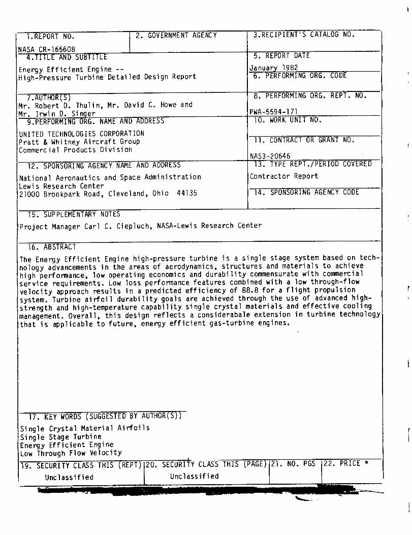
The Energy Efficient Engine high-pressure turbine is a single stage system based on tech-
nology advancements in the areas of aerodynamics, structures and materials to achieve
high performance, low operating economics and durability commensurate with commercial
service requirements. Low loss performance features combined with a low through-flow
velocity approach results in a predicted efficiency of 88.8 for a flight propulsion
system. Turbine airfoil durability goals are achieved through the use of advanced high-
strength and high-temperature capability single crystal materials and effective cooling
management. Overall, this design reflects a considerabale extension in turbine technology
that is applicable to future, energy efficient gas-turbine engines.
17. KEY WORDS (SUGGESTED BY AUTHOR(S))
Single Crystal Material Airfoils
Single Stage Turbine
Energy Efficient Engine
Low Through Flow Velocity
19.


FOREWORD
The Energy Efficient Engine ComponentDevelopmentand Integration Program isbeing conducted under para|lel National Aeronautics and Space Administrationcontracts to the Pratt & Whitney Aircraft Group, Commercial Products Divisionand the General Electric Company.The overall project is under the directionof Mr. Carl C. Ciepluch. Mr. John W. Schafer is the NASAAssistant ProjectManagerfor the Pratt & Whitney Aircraft effort under Contract NAS3-20646,andMr. M. Vanco is the NASAProject Engineer responsible for the portion of theprogram described in this report. Mr. William B. Gardner is the Pratt &Whitney Aircraft ProgramManagerfor the Energy Efficient Engine Program. Thisreport was prepared by Mr. R. Thulin, Mr. D. Howe, and Mr. I. Singer of Pratt& Whitney Aircraft.

TABLE OF CONTENTS
SECTION 1.0 SUMMARY
SECTION 2.0 INTRODUCTION
SECTION 3.0 DESIGN OVERVIEW
3.1 Design Goals and Challenges
3.2 High-Pressure Turbine General Description
3.3 Design Performance Data
SECTION 4.0 HIGH-PRESSURE TURBINE AERODYNAMIC DESIGN
4.1 Overview
4.2 Component Aerodynamic Design
4.2.1Flowpath Definition4.2.2 Airfoil Definition
4.2.3 High-Pressure and Low-Pressure Turbine Matching4.2.4 Aerodynamic Efficiency Status
4.2.5 Supporting Technology Programs
4.2.5.1Uncooled Rig Technology Program
4.2.5.2 Supersonic Cascade Program
4.2.5.3 Leakage Program
SECTION 5.0 AIRFOIL DURABILITY
5.1 Overview
5.2 Turbine Vanes
5.2.1 Vane Cooling Management System5.2.2 Vane Materials
5.2.3 Turbine Vane Durability Assessment5.3 Turbine Blades
5.3.1 Blade Cooling Management System5.3.2 Blade Materials
5.3.3 Turbine Blade Durability Assessment
SECTION 6.0 SECONDARY AIRFLOW SYSTEM
6.1 Overview
6.2 Secondary Flow Summary
6.3 Secondary Flow System Design Features
6.4 Thermal Analysis
SECTION 7.0 COMPONENT MECHANICAL DESIGN
7.1 Overview
7.2 Turbine Rotor Assembly
7.2.1 General Description7.2.2 Blades
7.2.2.1 Mechanical Design Features
7.2.2.2 Airfoil Vibration Analysis7.2.3 Blade Attachment
7.2.3.1 Mechanical Design Features
7.2.3.2 Structural Analysis
Page
9
9
lO
lO
II
19
19
19
20
22
25
30
3O
3O
31
34
38
38
38
42
45
48
48
48
5154
59
59
59
59
63
63
6876
76
76
iiiPREC-E_ii'_G PAG_ BLA_K NOT FIL,_ED
TABLEOF CONTENTS(Continued)Page
7.2.4 Disk 787.2.4.1 Mechanical Design Features 787.2.4.2 Structural Analysis 78
7.2.5 Sideplate and Vortex Plate 807.2.5.1 Mechanical Design Features 807.2.5.2 Structural Analysis 85
7.2.6 Air Seals 857.2.6.1 Mechanical Design Features 857.2.6.2 Structural Analysis 85
7.3 Vane and Inner Case 937.3.1 General Description 937.3.2 Vanes 93
7.3.2. l Mechanical Design Features 937.3.2.2 Structural Analysis 96
7.3.3 Inner Support, Tangential on-BoardInjection and High-Pressure CompressorSeal 96
7.3.3.1 Mechanical Design Features 967.3.3.2 Structural Analysis 97
7.4 Outer Caseand Outer Airseal 1007.4.1 Mechanical Design Features lO07.4.2 Structural Analysis I04
7.5 Active Clearance Control System 1047.5.1 General Description IO67.5.2 Blade Tip Clearance Definition I07
7.6 Number4 & 5 Bearing Compartmentand LubricationSystem If2
7.6.1 General Description I]27.6.2 Bearing Mechanical Design Features If27.6.3 Seals ll57.6.4 Lubrication System ll5
7.7 Turbine System Weight Summary ll7
SECTION8.0 HIGH-PRESSURETURBINECOMPONENTTESTRIGDESIGN8.1 Introduction8.2 General Description and Major Features8.3 Mechanical Design
8.3.1 Rotating Hardware8.3.2 Bearing and seals8.3.3 Air Seals8.3.4 Static Hardware
8.4 SecondaryFlow System and Thrust Balance8.5 Rig Instrumentation
8.5.1 Performance Instrumentation8.5.2 Structural Integrity Instrumentation
8.6 Facility/Rig Adaptation
SECTION9.0 CONCLUDINGREMARKS
VANEANDBLADEAIRFOIL COORDINATESLIST OF SYMBOLS
APPENDIXAAPPENDIXB
REFERENCES
I18If8If8120120121122131131132135135136
137
139146
148
iv

Number
2-I
3.2-I
4.2.1-I
4.2.2-I
4.2.2-2
4.2.2-3
4.2.2-4
4.2.2-5
4.2.2-6
4.2.2-7
4.2.2-8
4.2.2-9
4.2.2-I0
4.2.2-II
4.2.2-12
4.2.5-I
4.2.5-2
4.2.5-3
LIST OF ILLUSTRATIONS
Title
Logic Diagram of High-Pressure Turbine Effort
Energy Efficient Engine High-Pressure Turbine Component
High-Pressure Turbine Flowpath Definition
Vane Assumed Profiles For Inlet Temperature andPressure Loss
Vane Root Section Aerodynamic Contour and PressureDistribution
Vane Mean Section Aerodynamic Contour and PressureDistribution
Vane Tip Section Aerodynamic Contour and PressureDistribution
Turbine Vane Stacking
Effect of Inlet Temperature and Vane Loss Profile on
Blade Inlet Angle
Blade Root Section Aerodynamic Contour and PressureDistribution
Blade One-Quarter Root Section Aerodynamic Contour andPressure Distribution
Blade Mean Section Aerodynamic Contour and PressureDistribution
Blade One-Quarter Tip Section Aerodynamic Contour andPressure Distribution
Blade Tip Section Aerodynamic Contour and PressureDistribution
Turbine Blade Stacking
Turbine Uncooled Rig Performance Trends Showing Benefits
Decreasing the Cx/U and Increasing the AN z Parameter
Efficiency Gains Associated with High Blade ReactionLevels
Spanwise Distribution of Total Pressure Loss for theProfiled Wall Cascade
of
3
6
I0
12
13
13
14
14
15
16
16
17
17
18
18
21
22
23

Number
4.2.5-6
4.2.5-7
4.2.5-I0
4.2.5-II
4.2.5-12
4.2.5-13
5.2-I
5.2.1-1
5.2.1-2
5.2.1-3
5.2.1-4
5.2.1-5
5.2.1-6
5.2.1-7
5.2.1-8
LIST OF ILLUSTRATIONS (Continued)
Title
Predicted Vane Cooling Losses Compared to Test Results
Effect of Trailing Edge Ejection Flow on Blade PressureCoefficient
Plane Cascade Base Blade, Mean Section Trailing Eage
Cooling Air Ejection
Results of Blade-Disk Model Testing Showing Leakage inthe Attachment Area Is Less Than Predicted
Sealing Effectiveness of Rear Sideplate Design
Results With and Without W-Seals in the Blade PlatformArea
Promising Feather Seal Configurations Evaluated
Energy Efficient Engine High-Pressure Turbine Vane Inner
Attachment Leakage Rig
Comparison of 0.025 to 0.050 cm (0.010 to 0.020 in)
Thick Two-Piece Overlapping Feather Seals
Two-piece Overlapped Seals in Ground Versus Electro-
discharge Machined Slots
Combustor Exit Profile Used for Turbine Vane Durability
Assessment for Flight Propulsion System at Hot Day Sea
Level Takeoff Operating Conditions
Turbine Vane Cooling Design
Turbine Vane Inner Platform Cooling Scheme
Turbine Vane Outer Platform Cooling Scheme
Turbine Vane Inner Platform Heat Transfer Coefficients
Turbine Vane Outer Platform Heat Transfer Coefficients
Suction Surface Film Effectiveness
Vane Thermal Analysis Results
Pressure Wall Film Temperatures
Page
23
24
24
25
26
26
27
28
29
29
30
31
33
33
33
33
35
35
36
vi
Number
5.2.1-9
5.2.1-I0
5.2.1-II
5.2.3-I
5.2.3-2
5.3-]
5.3.1-I
5.3.1-2
5.3.1-3
5.3.1-4
5.3.3-I
5.3.3-2
5.3.3-3
5.3.3-4
6.2-I
6.3-I
6.3-2
6.3-3
6.4-I
6.4-2
LIST OF ILLUSTRATIONS (Continued)
Title
Suction Wall Film Temperatures
Vane Surface Temperature Profile
Vane Surface Heat Transfer Coefficients Used to
Determine Surface Temperature Profiles
Vane Limiting Strain Cycle
Predicted Strain
Turbine Vane Exit Profile for Flight Propulsion System at
Hot Day Sea Level Takeoff Operating Conditions
Turbine Blade Cooling System
Blade Thermal Analysis Results (Midspan Location)
Surface Temperature Profile
Blade Surface Heat Transfer Coefficients Used to
Determine Surface Temperature Profiles
Blade Limiting Strain Cycle
Predicted Strain
Blade Temperature Comparison with Creep Limits for Flight
Propulsion System at Hot Day Sea Level Takeoff OperatingConditions
Effects of Wall Thickness Tolerance on Blade Life
High-Pressure Turbine Secondary Flow System Map
Secondary Flow System Design Features
Mini Tangential On-Board Injection System
Flow Characteristics of Blade Coolant Supply System
Detailed Turbine Model Used for Thermal Analysis
Typical Transient Response of Turbine Disk During SnapAcceleration/Deceleration
36
37
37
39
39
40
41
43
44
44
45
46
47
47
49
52
52
53
55
56
vii

Number
6.4-3
6.4-4
7.1-I
7.2.1-I
7.2.1-2
7.2.1-3
7.2.2-I
7.2.2-2
7.2.2-3
7.2.2-4
7.2.2-5
7.2.2-6
7.2.2-7
7.2.2-8
7.2.2-9
7.2.2-I0
7.2.2-I l
7.2.2-12
7.2.2-13
7.2.2-14
LIST OF ILLUSTRATIONS (Continued)
Title
Detailed Turbine Case and Outer Airseal Model Used in
Thermal Analysis 57
Results of Temperature Analysis 58
High-Pressure Turbine Mechanical Configuration 60
High-Pressure Turbine Rotor Assembly 60
Energy Efficient Engine High Rotor Imbalance Response 61
Energy Efficient Engine High Rotor Critical Speeds and
Mode Shapes (Percent Rotor Strain Energy) 62
Turbine Blade Mechanical Configuration 63
Radial Taper in Turbine Blade To Minimize Stress 65
Degree of Tilt in the High-Pressure Turbine Blade to
Achieve the Desired Balance Between Gas Bending Load
Stresses and Stresses Resulting from Centrifugal Loads 65
Uncoated Blade Wall Thickness and Internal Rib Design 66
Core Support Method 67
Blade Tip Squealer Geometry 67
Graphical Display of Turbine Blade Defined by the NASTRANAnalytical Technique 68
Single Crystal Major Axes Orientation 69
High-Pressure Turbine Resonance Diagram 70
Blade Vibration Characteristics in First Mode 70
Blade Vibration Characteristics in Second Mode 71
Blade Vibration Characteristics in Third Mode 71
Blade Vibration Characteristics in Fourth Mode 72
Blade Vibration Characteristics in Fifth Mode 72
Page
f
i
viii
Number
7.2.2-15
7.2.2-16
7.2.2-17
7.2.2-18
7.2.3-I
7.2.4-I
7.2.4-2
7.2.4-3
7.2.5-I
7.2.5-2
7.2.5-3
7.2.5-4
7.2.6-I
7.2.6-2
7.2.6-3
7.2.6-4
7.2.6-5
7.2.6-6
LIST OF ILLUSTRATIONS
Title
Crystallographic Orientation
Predicted Frequencies Versus Crystal
Angle
Axial Shift in Crystal Orientation
Predicted Frequency with Modified
Blade Attachment Stress Results
High-Pressure Turbine Disk Design
Elliptical Cooling Air Supply Hole
(Continued)
Secondary Orientation
Configuration
Features
Schematic Showing Disk and Blade Deflections Caused
by First Coupled Mode Vibration
Boundary Conditions Used in Disk Structural Analysis
Flight Propulsion System Disk and Sideplate Calculated
Minimum Low Cycle Fatigue Life Levels
Disk Sideplate and Vortex Plate Design
Typical Sideplate Loads
Blade and Sideplate Assembly Sequence
Anti-Torque Pin Details
Turbine Seal Designs
Rear Thrust Balance Seal
Thrust Balance Seal Rotor and Stator Resonance Diagram
Thrust Balance Seal Rotor and Stator Coincidence Diagram
Number 4 Bearing Buffer Seal Assembly
Number 4 Bearing Buffer Seal Rotor and Stator Resonance
Diagram
Page
73
74
74
75
77
79
79
80
81
82
82
83
84
84
86
87
88
88
8g
90
ix

Number
7.2.6-7
7.2.6-8
7.2.6-9
7.2.6-I0
7.3.1-I
7.3.2-I
7.3.2-2
7.3.2-3
7.3.3-I
7.3.3-2
7.3.3-3
7.3.3-4
7.3.3-5
7.3.3-6
7.4-1
7.4.1-I
7.4.1-2
7.4.1-3
LIST OF ILLUSTRATIONS (Continued)
Title
Number 4 Bearing Buffer Seal Rotor and Stator Coincidence
Diagram
High-Pressure Compressor Discharge
High-Pressure Compressor Discharge
Resonance Diagram
High-Pressure Compressor Discharge
Coincidence Diagram
Hi_jh-Pressure Turbine Vane and
De sign
Turbine Vane Assembly
Seal Assembly
Seal Rotor and Stator
Seal Rotor and Stator
Inner Case Mechanical
Design Approach to Vane Leakage Control
Uncoated Vane Minimum Wall Thickness Distribution
Turbine Inner Support, Tangential On-Board Injection System,
and High-Pressure Compressor Seal Land Support System
Nozzle Configuration for the Primary Tangential On-BoardInjection System
Nozzle Configuration for the Secondary or Mini Tangential
On-Board Injection System
High-Pressure Compressor Discharge Seal Clearance Summary
Inner Vane Case Stress Summary
Case Structure Deflection Summary
High-Pressure Turbine Outer Case and Outer Airseal
Shoe Design
Materials Map
Assembly
Mechanical Design Features
Details of the Outer Airseal
Outer Case and Outer Airseal
9O
91
92
92
93
94
94
95
96
98
98
99
99
lO0
lOl
lOl
I03
I03
X

Number
7.4.2-I
7.4.2-2
7.4.2-3
7.5.1-I
7.5.2-I
7.5.2-2
7.5.2-3
7.5.2-4
7.5.2-5
7.6.1-1
7.6.1-2
7.6.2-I
7.6.3-I
7.6.4.1
8.2-I
8.3.1-I
8.3.3-I
8.3.3-2
8.3.3-3
8.3.3-4
8.3.3-5
LIST OF ILLUSTRATIONS (Continued)
Title Page
Shell Analysis Model 104
Temperature Map 105
Stress Map I05
High-Pressure Turbine Active Clearance Control System I06
Typical Rotor and Case Growth History ]07
Rotor and Case Response with Two Cooling Bleed Schedules 108
Effect of Mixed Bleed I09
Rotor and Case Response with Optimum Mixed Cooling BleedSchedule llO
Resultant Blade Tip Clearances Ill
Integrated Core/Low Spool Number 4 and 5 Bearing
Compartment - Temperature and Pressure Distribution atSea Level Takeoff -3oc (+25OF) Operating Conditions ll2
Number 4 and 5 Bearing Compartment Bearing and SealArrangement I]3
Number 4 and 5 Bearing Compartment - Locations of Maximum Stressand Deflection 114
Dry Face Seal Pressure, Temperature and Speed Experience I16
Oil Scupper Line for the Number 4 and 5 Bearing Compartment 1]7
High-Pressure Turbine Component Test Rig l]9
High-Pressure Turbine Component Test Rig Critical Speed and
Mode Shapes 120
High-Pressure Turbine Rig Thrust Piston Seal Resonance 123
High-Pressure Turbine Rig Thrust Piston Seal Coincidence 123
Front Compartment Front Airseal (Thrust Piston Seal) 124
High-Pressure Turbine Rig Front Bearing Rear Seal Resonance 125
High-Pressure Turbine Rig Front Bearing Rear Seal Coincidence 125
xi
Number
8.3.3-6
8.3.3-7
8.3.3-8
8.3.3-9
8.3.3-10
8.3.3-11
8.3.3-12
8.3.3-]3
8.3.3-14
8.3.3-15
8.3.4-I
8.4-I
LIST OF ILLUSTRATIONS (Continued)
Title
Front Compartment Rear Airseal
High-Pressure Turbine Rig High-Pressure CompressorDischarge Seal Resonance
High-Pressure Turbine Rig High-Pressure CompressorDischarge Seal Resonance
Hi
Hi
Hi
gh-Pressure
gh-Pressure
gh-Pressure
Compressor Discharge Seal
Turbine Rig Thrust Balance Seal Resonance
Turbine Rig Thrust Balance Seal Coincidence
Thrust Balance Seal and Damper
High-Pressure Turbine Rig Number 4 BearingResonance
High-Pressure Turbine Rig Number 4 Bearing Buffer SealCoincidence
Number 4 Bearing Buffer Seal - Rig
Active Clearance Control Growth Summary
High-Pressure Turbine Component Test Rig
Buffer Seal
Secondary F1 ows
Page
126
126
127
127
128
129
129
130
130
131
132
133
xii
LIST OFTABLES
Table No. Title
3.2-I Advanced Technology Design Concepts
3.3-I High-Pressure Turbine Predicted Performance at Aerodynamic
Design Point
4.l-I General Aerodynamic Parameters
4.2.2-I Gas Triangles
4.2.3-I High-Pressure Turbine Aerodynamics After Restaggering
4.2.4-I High-Pressure Turbine Efficiency Estimate Based on UncooledRig Test Results Aerodynamic Design Point
4.2.5-I Turbine Uncooled Rig Efficiency
5.2.2-I Vane Materials and Coatings
5.2.3-I Vane Life
5.3.2-I Blade Materials
5.3.3-I Blade Life
6.2-I Secondary Flow Status Summary
7.2.2-I High-Pressure Turbine Blade Stress Summary
7.2.3-I Blade Attachment Stress Summary
7.2.4-I Disk Life and Stress Summary
7.3.2-I Vane Materials and Coatings
7.5.2-I Flight Cycle For Clearance Analysis
7.5.2-II High-Pressure Turbine Active Clearance Control System
7.5.2-III High-Pressure Turbine Gapping Requirements
7..5.2-IV High-Pressure Turbine Tip Clearance Results
7.6.3-I Integrated Core/Low Spool Seal Operating Conditions
Page
5
8
9
12
19
20
22
38
40
45
46
50
63
77
78
95
I08
I09
Ill
Ill
ll6
xiii
Tabl e No.
7.7-I
8.3-I
8.3.2-I
8.3.2-11
LIST OF TABLES (Cont'd)
Title
Preliminary Weight summary For Integrated Core/Low Spool
High-Pressure Turbine Component
High-Pressure Turbine Component Rig Forced Response Results
Front Compartment Operating Conditions
Operating Conditions of the Rear Compartment Seals
Pa e
ll7
121
121
122
xiv

SECTION l.OSUMMARY
The high-pressure turbine designed for the Energy Efficient Engine is a singlestage configuration that utilizes technology advancements in the areas of
aerodynamics, structures and materials to enhance efficiency, durability and
performance retention. In addition, the single stage design offers a largesavings in initial engine cost, weight, and maintenance cost because of the
significant reduction in the number of components, especially expensive air-
cooled airfoils.
On the basis of aerothermal-mechanical analyses as well as results from sup-
porting technology programs, the high-pressure turbine meets the performanceand durability goals for both the integrated core/low spool and the flight
propulsion system. The predicted efficiency for the flight propulsion system
is 88.8 percent, which exceeds the goal of 88.2 percent. For the integratedcore/low spool, the expected test efficiency is 87.1 percent, which exceeds
the goal of 86.7 percent. The turbine aerodynamic design utilizes low loss
performance features with low through flow velocity to achieve this efficiency.
The turbine airfoils exceed the established durability/life requirements by
the use of advanced materials and efficient cooling management. Both the vanes
and blades are constructed with advanced high-temperature, high-strength sin-
gle crystal alloys and coated with an improved oxidation resistant coating.
For added thermal protection, vane platforms are coated with an advanced ther-
mal barrier coating. Acceptable metal temperatures are maintained through the
use of impingement, convection and film cooling techniques to minimize cooling
without compromising durability. Total cooling requirements are 2.75 and 6.41
percent of core engine airflow for the blade and vane, respectively.
Turbine performance is enhanced by the advancements in sealing technology.
Cooling air leakage is effectively reduced by the use of full ring, boltless
sideplates as well as the extensive use of feather seals and W-seals. An ac-tive clearance control system maintains close blade tip clearances throughout
the operating range. In this system, the blade tip seal is constructed of anabradable, ceramic material and the blade has an abrasive tip treatment. At
design conditions, the calculated clearance of 0.032 cm (0.0126 in) surpasses
the goal of 0.047 cm (0.0186 in).
The high-pressure turbine in the integrated core/low spool and envisioned for
the future flight propulsion system is also the same design for the High-Pressure Turbine Component Test Rig. This rig will be used to assess turbine
aerodynamic behavior and performance before the component is evaluated in the
integrated core/l ow spool.
Overall, the high-pressure turbine design for the Energy Efficient Engine re-
presents a considerable extension in the state-of-the-art of turbine tech-
nology. Much of this technology, especially the high temperature capabilitymaterials, will have wide application in derivative and future gas-turbine
engines.
SECTION2.0INTRODUCTION
The Energy Efficient Engine Component and Development Program, sponsored by
the National Aeronautics and Space Administration, is directed towards devel-
oping and demonstrating the technology to achieve greater fuel efficiency for
future comercial gas-turbine engines. The overall program goals outlined for
the program include a reduction in fuel consumption of at least 12 percent and
a reduction in direct operating cost of at least 5 percent relative to the
base Pratt & Whitney Aircraft JTgD-7A base engine. To demonstrate the tech-
nology to accomplish these goals, the Energy Efficient Engine Program is
organized into four tasks which involve:
Task l
Task 2Task 3
Task 4
Flight Propulsion System Analysis, Design and Integration
Component Analysis, Design and Development
Core Design, Fabrication and Test
Integrated Core/Low Spool Design, Fabrication and Test
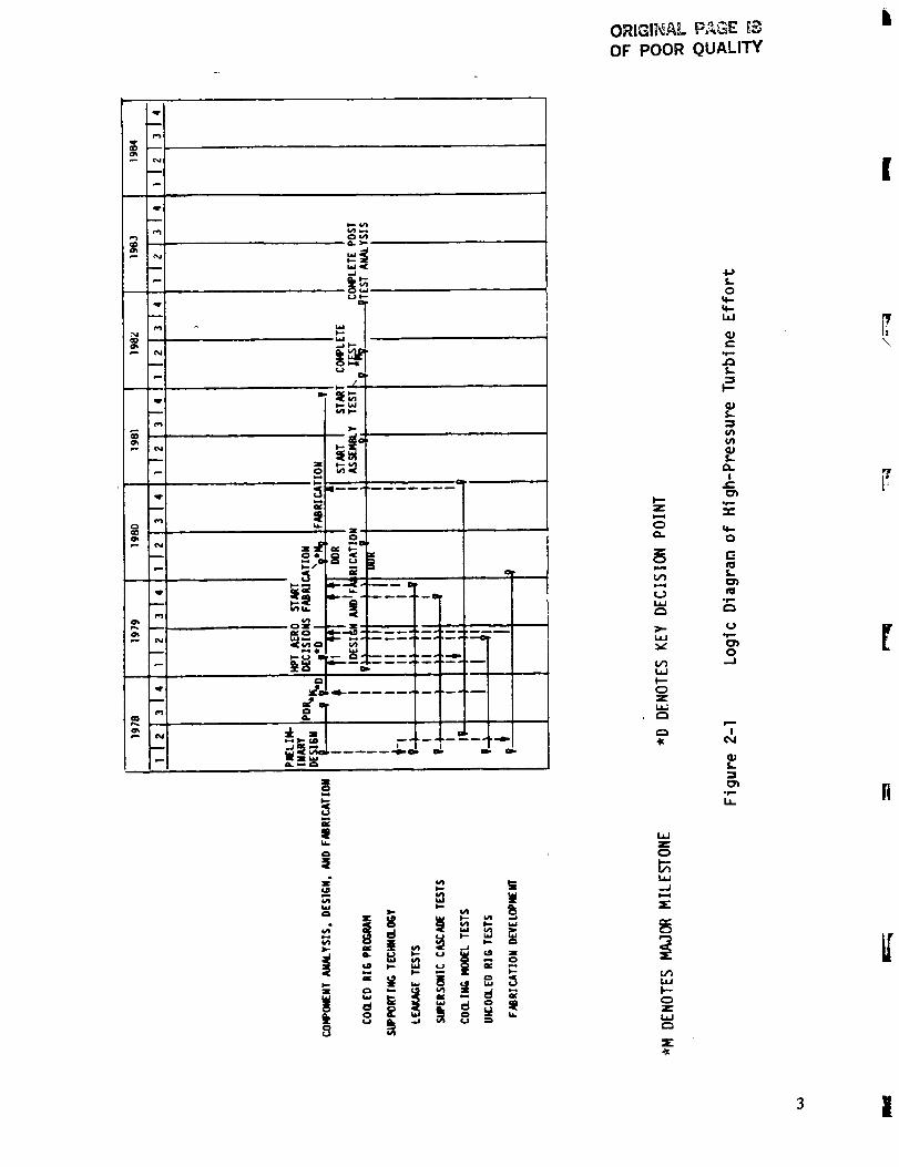
A major accomplishment under the Task 2 effort has been the design of an ad-
vanced high-pressure turbine system. Figure 2-I presents a logic diagram of
the high-pressure turbine design effort within the overall Energy EfficientEngine Program.
The high-pressure turbine component has been designed to meet the requirementsfor the flight propulsion system and the integrated core/low spool. In addi-
tion, the turbine design is the same for the High-Pressure Turbine ComponentTest Rig, which will be used to assess turbine aerodynamic performance before
the component is tested in the integrated core/low spool. The design empha-
sizes the utilization of advancements in the areas of aerodynamics, materials/
cooling management and structures to achieve aggressive performance and dur-
ablllty design goals.
This report presents a comprehensive description of the aerodynamic and
thermal-mechanical design of the Energy Efficient Engine high-pressure turbine.
A description of the high pressure turbine rig design is also presented.
OrlGI|_AL P,_GE _ b
OF POOR QUALITY
u
- I
o
.r.
5/ =_/ !
,_--. _=L_,==
===_=
_ = = 8 = -
L_JZ
W
ZL_J
O_
oe=.
L&.fl
3 |
SECT ION 3.0
DESIGN OVERVIEW
3.1 DESIGN GOALS AND CHALLENGES
The Energy Efficient Engine high-pressure turbine concept is a single stage
configuration capable of high work extraction and high system efficiency.
Performance and durability design goals established for the turbine component
address the overall program goals as well as the requirements for a future
commercial flight propulsion system.
The turbine efficiency goal for the flight propulsion system is 88.2 percent.
This represents a considerable increase in efficiency compared to a current
technology single-stage design. However, the expected test efficiency goal forthe integrated core/low spool is lower -- 86.7 percent. This is based on the
anticipation that leakage rates and part quality in the integrated core/low
spool vehicle will be worse than for a fully developed flight propulsion
system. In addition, restagger for compatibility with the increased annulus
low-pressure turbine and rematching associated with other component perfor-
mance losses further reduce efficiency.
Other key design goals include a specific work output of 448,000 J/kgm (192.96Btu/Ibm), an expansion ratio of 4.0, a combined turbine cooling/leakage flow
rate of If.2 percent of core engine flow, and a rim speed of 527 m/sec (1730ft/sec).
In terms of component durability, the flight propulsion system design goalsconsist of a vane and blade life of lO,O00 hours, and disk life of 20,000
hours. In addition, an airfoil coating life goal of 6000 hours was established.
The achievement of these performance and durability goals with a single stage
turbine introduces certain design challenges. The two most prominent challenges
center around maintaining acceptable blade stress with the high rim speed
operation and minimizing system cooling flows and leakage losses. The follow-
ing paragraphs outline how these challenges have been approached, and the
specific design features that contribute to meeting the turbine performanceand durability goals are described in the next section.
To achieve the efficiency goal, the single stage turbine must operate at a
high ratio of wheel speed to specific work (high velocity ratio) and a low
ratio of through flow to wheel speed (Cx/U). The aerodynamic parameters of
velocity ratio and Cx/U can be translated into blade stress and bladeattachment stress, which results in a high AN 2 (the product of annulus area
and wheel speed squared). It is this structural concern that constrains attain-
ing a high level of aerodynamic performance with a highly loaded, single stage
turbine. In the design of the Energy Efficient Engine turbine, this challengehas been addressed by the application of high strength blade and disk alloys,
along with increased blade taper.
4
The efficient management of cooling flow is essential since significant
penalties in efficiency as well as increases in fuel burned result from thelarge percentage airflow required to cool the turbine components. From a per-
formance standpoint, the goal is to minimize the a_.lountof coolant, while
maintaining acceptable metal temperatures to meet durability requirements. Theturbine design addresses this challenge by utilizing advanced high temperature
capability materials for the airfoils along with thermal barrier coatings and
an efficient cooling management system. This combination reduces the cooling
requirement by approximately 30 percent in comparison to current-technology
conL1ercial engines.
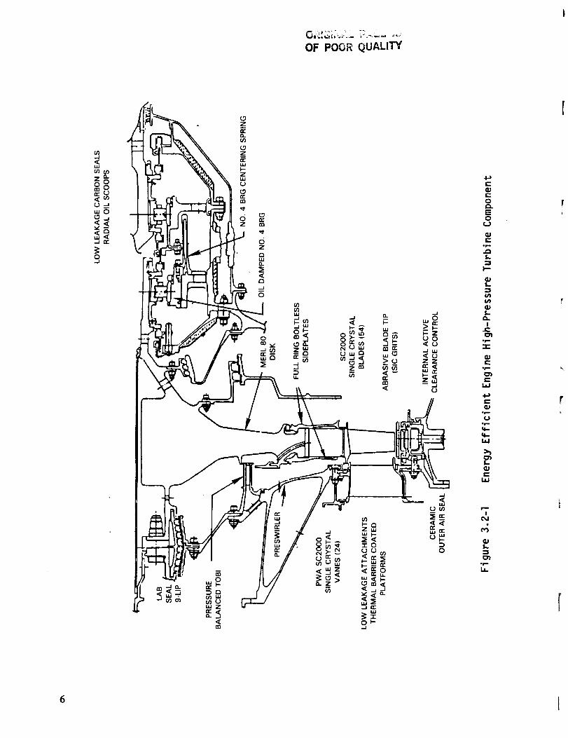
3.2 HIGH-PRESSURE TURBINE GENERAL DESCRIPTION
A cross sectional view of the high-pressure turbine for the Energy Efficient
Engine is presented in Figure 3.2-I.
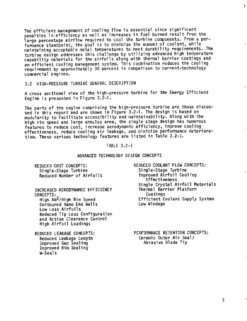
The parts of the engine comprising the high-pressure turbine are those discus-sed in this report and are shown in Figure 3.2-I. The design is based on
modularity to facilitate accessibility and maintainability. Along with the
high rim speed and large annulus area, the single stage design has numerousfeatures to reduce cost, increase aerodynamic efficiency, improve cooling
effectiveness, reduce cooling air leakage, and minimize performance deteriora-
tion. These various technology features are listed in Table 3.2-I.
TABLE 3.2-I
ADVANCED TECHNOLOGY DESIGN CONCEPTS
REDUCED COST CONCEPTS:
Si ngle-Stage TurbineReduced Number of Airfoils
INCREASED AERODYNAMIC EFFICIENCY
CONCEPTS:
High AN2/High Rim SpeedContoured Vane End Walls
Low Loss Airfoils
Reduced Tip Loss Configurationand Active Clearance Control
High Airfoil Loadings
REDUCED COOLANT FLOW CONCEPTS:
Singl e-Stage Turbine
Improved Airfoil CoolingEffec tiveness
Single Crystal Airfoil MaterialsThermal Barrier Platform
Coatings
Efficient Coolant Supply System
Low Windage
REDUCED LEAKAGE CONCEPTS:
Reduced Leakage Length
Improved Gap Sealing
Improved Rim SealingW-Seals
PERFORMANCE RETENTION CONCEPTS:
Ceramic Outer Air Seal/
Abrasive Blade Tip
OF POOR QUALITY
c/),,.J
l.U{/)
z0_0n--,<
14J
_.1
O..1
n
_J
5
I--c_z_u_Ul--
"ro
..I
e,.
0
o
t.
!
*i,m
_J
_J
uJ
_J
°_
U.
The single stage configuration offers a potentially large savings in enginecost, weight and maintenance costs because of a significant reduction in the
number of components, especially expensive air-cooled turbine airfoils. In
comparison to the base engine two stage version, the single stage turbine has43 percent fewer airfoils. Also, the overall number of turbine parts has been
reduced by elimination of the second stage disk, seals, outer airseals and
related components.
The capability to operate at higher blade loadings because of a reduction in
airfoil number results in substantial performance gains. Other performanceenhancement features include contoured vane endwalls and an active clearance
control system to minimize operating clearances at cruise conditions.
A reduction in cooling flow with no compromise in durability is obtained pri-
marily through the use of advanced high-temperature materials and efficient
airfoil cooling methods. Both the vane and blade materials are single crystalalloys which offer superior creep strength properties, along with good resist-
ance to thermal fatigue. In addition, the vane platforms are coated with a
thermal barrier coating for additional temperature capability. The internal
cooling system of the airfoils is efficiently designed to promote a high heattransfer rate with a minimum of coolant airflow.
A substantial reduction in leakage has been achieved by the use of advancedsealing techniques and the relatively fewer number of airfoils, which reduces
leakage sources. Besides the ceramic seals in the active clearance control
system, leakage is reduced in the blade attachment by the use of full-ring
boltless sideplates and W-seals. Also, feather seals are employed in the vaneinner and outer platforms to reduce leakage.
Turbine performance retention in the flight propulsion system will be enhanced
by an advanced blade tip sealing system. The turbine blade incorporates an
abrasive material tip treatment that is used in conjunction with an abradableceramic outer airseal.
3.3 DESIGN PERFORMANCE DATA
The engine performance data used to design the high-pressure turbine are a
combination of flight propulsion system predictions and integrated core/low
spool expectations. This design approach was taken to maximize the performance
of the high-pressure turbine during integrated core/low spool testing, whilestill demonstrating a component that is representative of the flight propul-
sion system. As a result, the design uses power and flow levels expected for
the integrated core/low spool, while assuming predicted flight propulsionsystem levels for the aerodynamic losses. This approach results in a high-
pressure turbine exit flow parameter that is incompatible with the design
inlet flow parameter of the low-pressure turbine. This flow parameter discrep-
ancy requires that the high-pressure turbine blade be restaggered for the in-
tegrated core/low spool test.
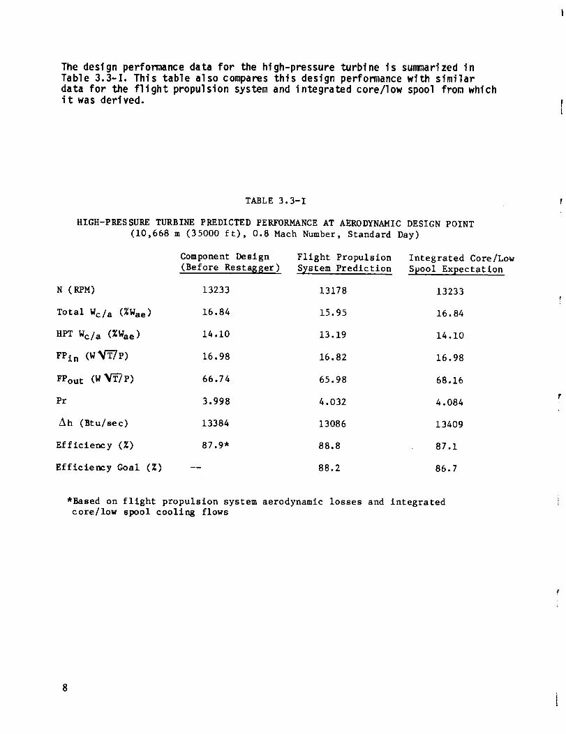
The design performance data for the high-pressure turbine is summarized inTable 3.3-I. This table also compares this design performance with similardata for the flight propulsion system and integrated core/low spool from whichit was derived.
TABLE 3.3-I
HIGH-PRESSURE TURBINE PREDICTED PERFORMANCE AT AERODYNAMIC DESIGN POINT
(10,668 m (35000 ft), 0.8 Mach Number, Standard Day)
Component Design Flight Propulsion Integrated Core/Low
(Before Restagger) System Prediction Spool Expectation
N (RPM) 13233 13178 13233
Total Wc/a (%Wae) 16.84 15.95 16.84
HPT Wc/a (%Wae) 14.10 13.19 14.10
FPIn (W_P) 16.98 16.82 16.98
FPou t (W_P) 66.74 65.98 68.16
Pr 3.998 4.032 4.084
Ah (Btu/sec) 13384 13086 13409
Efficiency (%) 87.9* 88.8 87.1
Efficiency Goal (%) -- 88.2 86.7
*Based on flight propulsion system aerodynamic losses and integrated
core/low spool cooling flows
SECTION 4.0
HIGH-PRESSURE TURBINE AERODYNAMIC DESIGN
4.1 OVERVIEW
The aerodynamic definition of the high-pressure turbine was based on a seriesof analyses to establish the flow_ath, airfoil contours, solidity and matching
characteristics that achieve the highest level of performance within the con-straints of the basic mechanical definition. Moreover, the final design was
influenced by results obtained from different supporting technology programs
that were in progress concurrent with the design process. These programs
served as design and diagnostic tools to address unique requirements of the
component design. The different programs consisted of the Uncooled Rig Program,
the Supersonic Cascade Rig Program and the Leakage Program. The contribution
of these programs to the turbine aerodynamic design is summarized in Section4.2.5.
As a result of these design analyses and supporting technology programs, thelow throughflow velocity and high reaction aerodynamic approaches were
selected as the basis for the component design. Also, the airfoil design
philosophy of low uncovered turning, low exit wedge angle was maintained. The
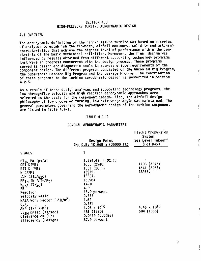
general parameters governing the aerodynamic design of the turbine componentare listed in Table 4.l-I.
TABLE 4.l-I
GENERAL AERODYNAMIC PARAMETERS
Design Point(Mn 0.8; I0,668 m (35000 ft)
F1 ight Propulsion
SystemSea Level Takeoff
(Hot Da_,)
STAGES
PTIN Pa (psia)CET K(OR)
RIT K (OR)N (RPM)
AH (Btu/sec)
FPin (W _T/PT)
_IA (%Wae)
Reac tio n
Velocity RatioNASA Work Factor (Ah/u 2)
Cx UAN ( (IN2 RPM 2)
URIM m/see (ft/sec)Clearance cm (fn_
Efficiency (Design)
],324,49] (]92.])
1633 (2940)
1561 (2811)13232.
13384.
16.984
14.10
4.0
43.0 percent0.556
l.62
0.3514.06 x lOlO
481 (l580)
0.0469 (0.0185J87.9 percent
1708 (3076)
1641 (2955)13866.
4.46 x lOlO
5O4 (1655)
9
I
_r _ _
ORIG!!:_L F:--,._-'_':.:_'OF POOR QUALITY
As described previously in Section 3.3, a mixture of cycle performance datafrom flight propulsion system predictions and the integrated core/low spool
expectations was used in the design of this turbine. The design intent was to
satisfy flight propulsion system requirements through application of the
results gained from the supporting technology programs. As work progressed it
became apparent that the high-pressure turbine in the integrated core/low
spool design should be matched to the expected integrated core/low spool per-
formace. The turbine design, therefore, uses the power and flow requirementsof the integrated core/low spool while assuming the level of aerodynamic
losses in the flight propulsion system. The high-pressure turbine exit flow
parameter resulting from this approach does not match the integrated core/low
spool low-pressure turbine flow parameter (Section 4.2.3). To achieve the
desired low-pressure turbine inlet aerodynamic conditions in the integrated
core/low spool, the high-pressure turbine blade was restaggered open 0.25degree from its aerodynamic definition.
4.2 COMPONENT AERODYNAMIC DESIGN
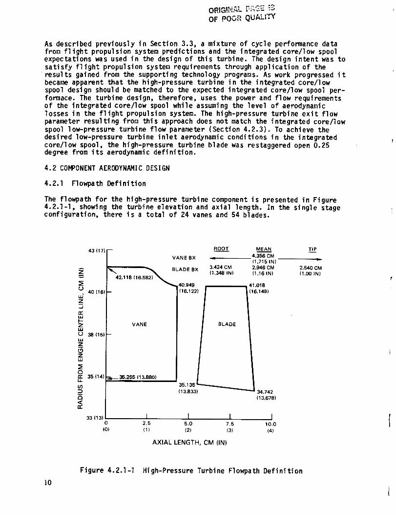
4.2.1 Flowpath Definition
The flowpath for the high-pressure turbine component is presented in Figure4.2.1-I, showing the turbine elevation and axial length. In the single stageconfiguration, there is a total of 24 vanes and 54 blades.
43 (17) --
A
Znv
040 (161
Z
...I
n.-uJI--ZIJJ{J 38 (151illZ
(.9Ziii
orr 35 (14)u.
(/):::)
(3,<rr
33 (1310
(0)
VANE BX
'_ _ BLADE BX
42.118 (16.582) _._40.949
VANE
=b_ 35.255 (13.880)
ROOT MEAN
4.356 CM
(1.715 IN)
3.424 CM 2.946 CM
(1.348 IN) (1.16 IN)
41.018
(16.1221 (16.1491
35.135 t
( 13.8331 34.742
(13.678)
1 I I I2.5 5.0 7.5 10.0
(1) (2) (3) (4)
AXIAL LENGTH, CM (IN)
TIP
2.540 CM
(1.00 IN)
]0
Figure 4.2.1-I Hi gh-Pressure Turbi ne Flowpa th Defi ni tion
The vanes are characterized by aerodynamic sections having a blunt leadingedge and a long chord with the maximum airfoil thickness near the leadingedge. The inner vane endwall is cylindrical, while the outer is contoured inan "S" shape (Figure 4.2.1-1). The large aerodynamic section thickness reducesthe losses associated with the introduction of cooling flow and the S-walldesign reduces endwall pressure losses. In addition, the number of vanes mini-mizes blockage as well as optimizes the positioning of the vanes with thecombustor fuel injector nozzles.
The blades are highly tapered with a conical inner wall. Blade axial chord
taper was selected to accommodate stress requirements. Also, the stage isdefined with a high reaction level to enhance efficiency. On the basis of
design analyses, it was shown that higher reaction levels produced higherefficiencies. The maximum allowable reaction level for this turbine design was
limited to 43 percent because increasing the axial pressure load on the rotorresulted in excessive bearing loadings and consequent durability concerns.
Experimental testing in the supporting Uncooled Rig Program demonstrated the
benefit of the 43 percent reaction level in comparison to a lower level of 35
percent.
4.2.2 Airfoil Definition
Several analytical techniques were used to establish the turbine airfoil
definitions. A streamline computer design simulation generated the radial
aerodynamic environment. This information serves as input to the interactive
airfoil design system for a definition of the external contour of the airfoil.
Analyses are then performed to ascertain pressure distribution and boundary
layer characteristics. On the basis of these results, iterations of the air-
foil shape are made to optimize pressure distribution, boundary layer and lowloss characteristics.
Using these methods, vane sections were analytically defined. The sections
were designed so that the flow accelerated past the throat area with low,smooth backend diffusion. The uncovered turning and exit wedge angle were
optimized to minimize pressure loss. Blade sections were designed to the same
pressure distribution criteria as the vane. Uncovered turning and exit anglewere optimized to reduce blade profile, trailing edge and shock losses. Results
from the Supersonic Cascade Program verified the final airfoil shapes. Signi-ficant test results relating to the airfoil aerodynamic design are presented
in Section 4.2.5.
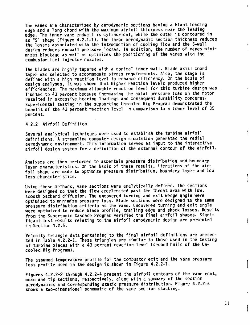
Velocity triangle data pertaining to the final airfoil definitions are presen-ted in Table 4.2.2-I. These triangles are similar to those used in the testing
of turbine blades with a 43 percent reaction level (second build of the Un-
cooled Rig Program).
The assumed temperature profile for the combustor exit and the vane pressure
loss profile used in the design is shown in Figure 4.2.2-I.
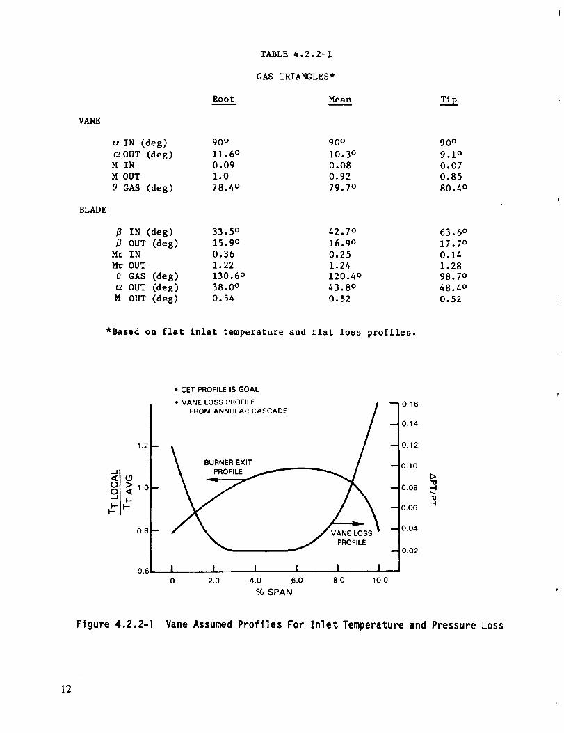
Figures 4.2.2-2 through 4.2.2-4 present the airfoil contours of the vane root,mean and tip sections, respectively, along with a summary of the section
aerodynamics and corresponding static pressure distribution. Figure 4.2.2-5shows a two-dimensional schematic of the vane section stacking.
VANE
BLADE
Root
TABLE 4.2.2-1
GAS TRIANGLES*
Mean zlp
IN (deg) 90 ° 90 ° 90 °
OUT (deg) 11.6 ° 10.3 ° 9.1 °M IN 0.09 0.08 0.07
M OUT 1.0 0.92 0.85
e GAS (deg) 78.4 ° 79.7 ° 80.4 o
IN (deg) 33.5 ° 42.7 ° 63.6 °
OUT (deg) 15.9 ° 16.9 ° 17.7 o
Mr IN 0.36 0.25 0.14
Mr OUT 1.22 1.24 1.28
e GAS (deg) 130.6 ° 120.4 ° 98.7 o
OUT (deg) 38.0 ° 43.8 o 48.4 °
M OUT (deg) 0.54 0.52 0.52
*Based on flat Inlet temperature and flat loss profiles.
12
91< ,.o
0.8
0.6
• CET PROFILE IS GOAL
"vAF"_°_OSS':LT'_ASCA0E / 701_-10.14
_lO.O6 3
., I I I I I I0 2.0 4.0 6.0 8.0 10.0
% SPAN
Figure 4.2.2-1 Vane Assumed Profiles For Inlet Temperature and Pressure Loss
12
o.o (o.o__-
0.5 (0.21 ,--
1.0 10.4) --
1.5 (0.6) --
2.0 (0.8) --
2.5 (1.01 --
3.0 (1.2) --
3.5 (1.41 --
4.0 (1.6} --
4.5 (1.8)
5.0 (2.0) --
Z 5.5 12.2)
_t_ (2.4)6.O
6.5 12.6i
7.0 (2.8)
7.5 (3.0
8.0 13.2
8.5 13.4]
9.0 (3.61
9.5
10.0 (4.0
10,5 (4.2
0,0 1.0
(0.0) (0.4)
Figure 4.2.2-2
0.0 10.0) --
0.5 (0.2) --
1.0 10.4) --
1.5 10.6)
2.0 (0,8)
2.5 I1.0) --
3.0 11.2)
3.5 11.4)
4.0 11.6)
4,5 (1.8
5.0
5.5 (2.21
6.0 i2.4
6.5 (2.6
7.0 (2.8
7.5 (3.(;
8.0 (3,2
8,5 13,4)
9,0 (3.6
9,5 {3.8
10.0 14.0
10.5 (4.2
0,0
(0.01
Figure 4.2.2-3
r
OF POOR _iO;¢=_d(.VANE ROOT SECTION
PRESSURE DISTRIBUTION
I--O-
1.O
O,9
0.7
0.6
0,5:
o.4i I I 7- I00( 020 040 060 080 _,00
X/B
RADIUS 35.255 crn 113.880 in)
# FOILS 24
AXIAL CHORD 4.356 crn 11.715 in)
L.E. DIAMETER 1.334 cm (0.525 _n)
T.E. DIAMETER 0.163 cm ((0.064 inl
UNCOVERED TURNING 10.0 °
EXIT WEDGE ANGLE 4.0 °
MMA X 1.012
INLET FOIL ANGLE 90.0 °
EXIT FOIL ANGLE 11.562 °
CHORD 10.256 cm 14.038 in)
2.0 3,0 4.0
(0.8) (1.2) (1.6)
CM (IN)
Vane Root Section Aerodynamic Contour and Pressure Di stri buti on
F-O.
VANE MEAN SECTION
PRESSURE DISTRIBUTION
1,0 %"T_'2_"-- _ __
i i.0.4- I I I I i
0.0 0.2 0.4 0.8 0.9 1.0
X/B
1.0 2.0 3.0 4.0
(0.41 (0.8) I1.21 11,6)
CM (IN)
Vane Mean Section
RADIUS 38.103 CM (15.001 IN)
# FOILS 24
AXIAL CHORD 4.356 CM (1.715 IN)
L.E, DIAMETER 1,334 CM (0.525 IN)
T.E. DIAMETER 0,163 CM (0.064 IN)
UNCOVERED TURNING 9.0 °
EXIT WEDGE ANGLE 4.0 °
MMA X 0,927
INLET FOIL ANGLE 90.0 °
EXIT FOIL ANGLE 10.312 =
CHORD 10.899 CM (4,291 IN)
Aerodynamic Contour and Pressure Dis tribution
13 I

OF .r:t)_RQUaLiTY
0.0 (OO)
O.5 I0.2)
1.0 (0,4}
1.5 (0.61
2.0 (0.81
2.5 (1 .OI
3.0 (1.2)
3.5 (1.4)
A 4.0 (1.6)
z 4.5 SIB_
5,0 12.01
_J 5,5 12.2)
6.0 (2,4)
6,5 (2,6)
7.0 12.8l
7.5 (3.OI
8.0 (3.2}
8.5 (3,41
9.0 (3,6)
9.5 (3.8)
10.0 (40)
10.5 (4.2) 1 I I I I III II
0.0 1,0 2.0 3.0 4.0
(0.0) IO4) (0.8) 11.21 (1.6)
CM (IN)
VANE LEADING EDGE TIP SECTION
PRESSURE DISTRIBUTION
1.1
1.0
0.9
P/PT 0.8
0.7
0.6
0,5
0.
0.00
I I I I I0.20 0.40 0.60 0.80 1,00
X/BX
RADIUS 42.11B CM (16.582 IN)
# FOI LS 24
AXIAL CHORD 4.356 CM (1.715 IN)
L.E. DIAMETER 1.333 CM 10.525 INi
T.E. DIAMETER 0.162o CM (0.064 IN)
UNCOVERED TURNING 10._)EXIT WEDGE ANGLE 4.0
MMAX 0.85_)
INLET FOIL ANGLE 90,0 e
EXIT FOIL ANGLE 8.509
CHORD 11,829 CM (4,657 IN}
Figure 4.2.2-4 Vane Tip Section Aerodynamic Contour and Pressure Distribution
]4
Figure 4.2.2-5 Turbine Vane Stacking
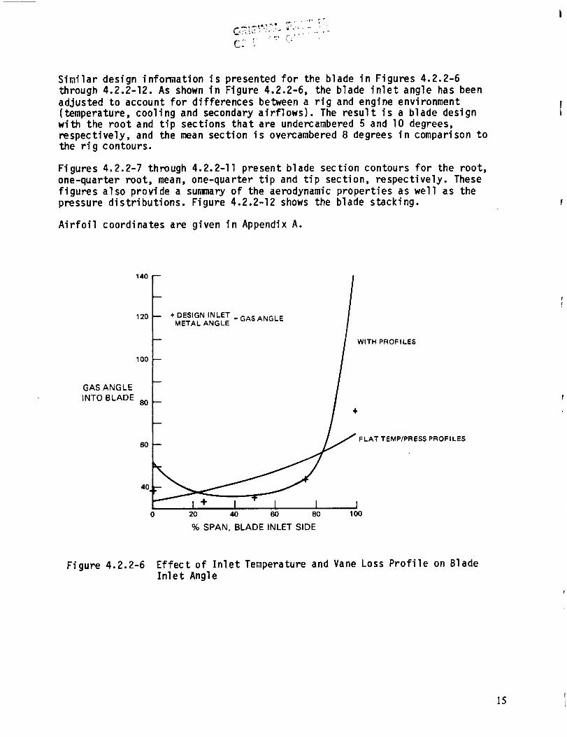
Similar design information is presented for the blade in Figures 4.2.2-6
through 4.2.2-12. As shown in Figure 4.2.2-6, the blade inlet angle has been
adjusted to account for differences between a rig and engine environment(temperature, cooling and secondary airflows). The result is a blade design
with the root and tip sections that are undercambered 5 and I0 degrees,
respectively, and the mean section is overcambered 8 degrees in comparison to
the rig contours.
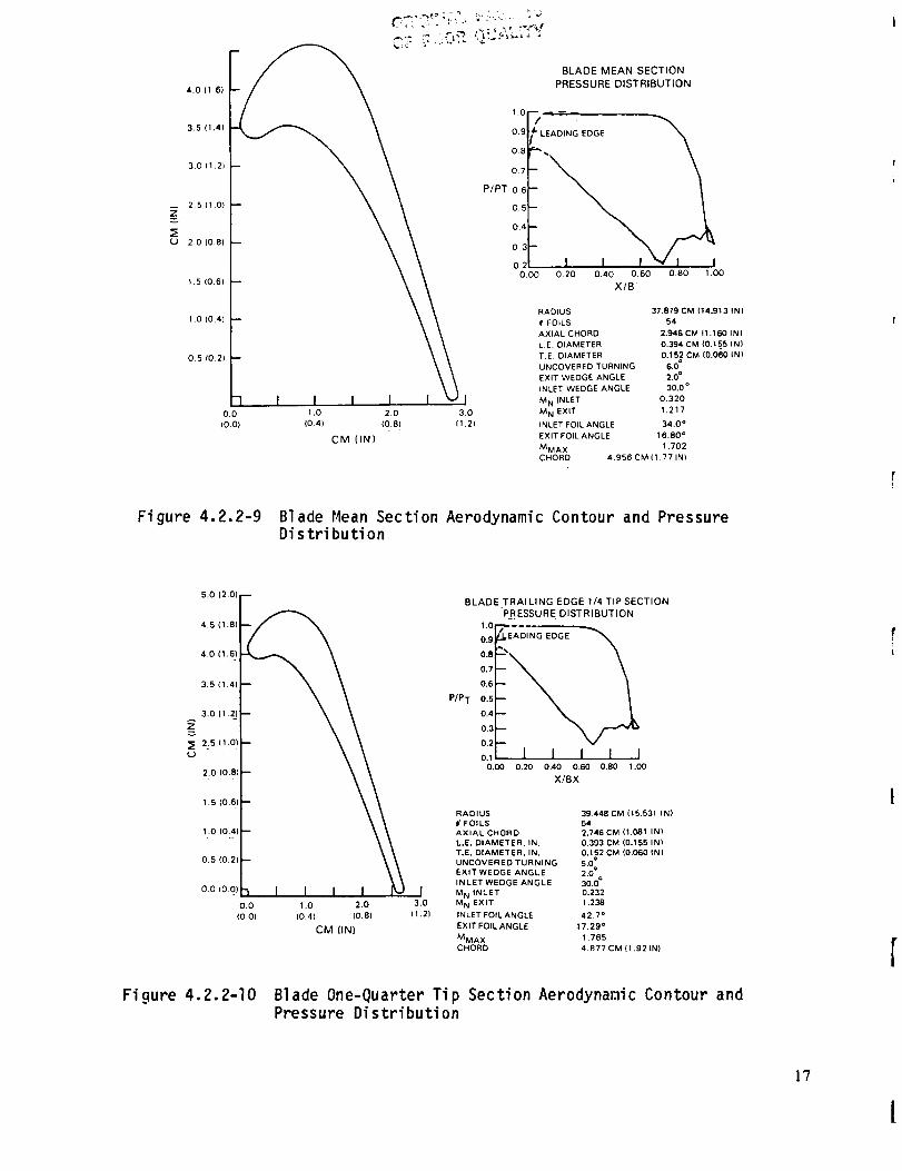
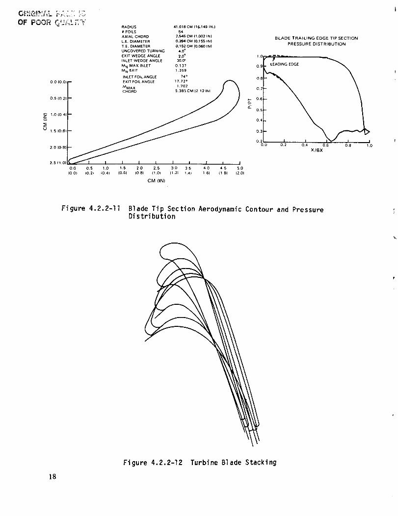
Figures 4.2.2-7 through 4.2.2-II present blade section contours for the root,
one-quarter root, mean, one-quarter tip and tip section, respectively. These
figures also provide a sumary of the aerodynamic properties as well as the
pressure distributions. Figure 4.2.2-12 shows the blade stacking.
Airfoil coordinates are given in Appendix A.
14(]
120
1O0
+ DESIGN INLET = GAS ANGLEMETAL ANGLE
WITH PROFILES
GAS ANGLE
INTO BLADE8O
6oFLAT TEMP/PRESS PROFILES
4O
+ I I I I0 20 40 60 80 1O0
% SPAN, BLADE INLET SIDE
Figure 4.2.2-6 Effect of Inlet Temperature and Vane Loss Profile on BladeInlet Angle
]5

U
OF POOR QUALITY
4.5 (1,8)
4.0 11,6)
3,5 11.4:3.0 (1.2)
2.5 (1.0)
1,0 (0,41)_
0.5 (0.;
0.0 I0.0)
0,0 0,5 1.0 1,5 2.0 2.5 30 3.5
(0.0) (0,2) (0.4l (0.6) 10.8) (1.01 (1.2t (1.4)
CM (IN)
BLADE ROOT SECTION
PRESSURE DISTRIBUTtON
1.0
0.8
0.7
P/PT 0.6
0.5
0.4
0.3
2.0
0.50 0.60 0.70 0,.80 0.90 1.00
X/BX
RADIUS 34.742 CM (13.678 IN)
iit FOILS 54
AXIAL CHORD 3.424 CM (1.348 IN)
L.E. DtAMETER 0.393 CM t0.156 IN)
T.E. DIAMETER 0.1_2 CM (0.060 IN)
UNCOVERED TURNING 8.0-
EXIT WEDGE ANGLE 2.0 °
SNLET WEDGE ANGLE 30.0 °
M N iNLET 0.349
M N EXIT 1.189
INLET FOIL ANGLE 38.5 °
EXIT FOIL ANGLE 1592 °
MMA X 1,559
CHORD 4.242 CM (1.67 IN)
Figure 4.2.2-7 Blade Root Section Aerodynamic Contour and PressureDistribution
4.5 (1.8)
4.0 ci .6i
3.5 (1.4)
3,0 (1.21
2.5 (1 .O)
(J 2.0 (0.8}
lO (o4i
0.5 10.21
0,0 10_0)
Fi gure
i
0.0 1.0 2,0 3.0
(0.01 (0.4) 10.8) (1 2(
CM (IN)
.. B LADE_ 1/4- ROOT SECTION
PRESSURE DISTRIBUTION
1.0 _ --- ,
E7
P/PT 0:6
o:s0:4'
0,2
O.O0 0.20 0.41) 0.60 0.80 1.1_
X/BX
RADIUS 36,311 CM (14.296 IN)
//FOILS 54
AXIAL CHORD 3.185 CM (1.254 IN)
L.E. DIAMETER. IN. 0.393 CM (0.155 IN)
T.E. DIAMETER, IN. 0.152 CM (0,060 IN)
UNCOVERED TURNING 7.0 °
EXIT WEDGE ANGLE 2.0 °
IN LET WEDGE ANGLE 30.0 °
M N INLET 0.371
M N EXIT 1.202
INLET FOIL ANGLE 32.7 =
EXIT FOIL ANGLE 16.39
MMA X 1.603
CHORD 4.267 CM (1.68 IN)
4.2.2-8 Blade One-Quarter Root Section Aerodynamic Contour andPressure Distribution
16 i
Z
_Etj
4.0 (1.6)
3.5 (1.41
3.0 (1.2)
2.5 (1.0)
2.0 IO.8}
1.0 (0.4)
0.0 1 ,O 2.0 3.0
(O.O} (0.4) (0.8) (1.21
CM (IN)
BLADE MEAN SECTION
PRESSURE DISTRIBUTION
P/PT
0.9 DING EDGE
0.8 •
0.7
0.E
0.5
0.4 _
0.3'
0.2
0.00 0.20 0.40 0.60 0.80 1.00
X/B"
RADIUS 37.879 CM (14.913 IN}
# FOILS 54
AXIAL CHORD 2.946 CM ll .160 INI
L.E. DIAMETER 0.394 CM (0.15_5 IN)
T.E. DIAMETER 0.152 CM (0.060 IN)
UNCOVERED TURN)NG 6.0
EXIT WEDGE ANGLE 2.0 =
INLET WEDGE ANGLE 30.0 °
M N INLET 0.320
M N EXIT 1.217
INLET FOIL ANGLE 34.0 °
EXIT FOIL ANGLE 16.80 °
MMA X 't .702
CHORD 4.956 CM ( I. 77 IN)
Figure 4.2.2-9 Blade Hean Section Aerodynamic Contour and PressureDistribution
Fi gure
5.0 (2.0) F
4.5 (1.8)F_
\\
2,0 10.81 -- _
1.6 (0. 6) -- _
1..0 IO:,, -- _
O.O 1 .O 2.0
(0.0) IDA} (O.B)
CM (IN)
0.8
0.7
0.6
P/PT 0.5
0.4
0.3
0.2
0.1
I3.0
I1.21
BLADE TRAILING EDGE 1/4 TIP SECTION
PRESSURE DISTRIBUTION
1'0 '_'EADING EDGE0.9
i',,2, I I I I I
0._ 0.20 0.40 0.60 0.80 1 .IXl
X/BX
RADIUS 39.448 CM (16.531 IN)
f/ FOILS 54
AXIAL CHORD 2.746 CM (1.081 IN)
L.E. DIAMETER. IN. 0.393 CM (0.155 IN)
T.E. DIAMETER. IN. 0.152 CM (0.060 IN)
UNCOVERED TURNING 5.00
EXIT WEDGE ANGLE 2.0°0INLET WEDGE ANGLE 30.0
M N INLET 0.232
M N EXIT 1.238
INLET FOIL ANGLE 42.7 °
EXIT FOIL ANGLE 17.29 °
MMA X 1.76E
CHORD 4.877 CM (1.92 IN)
4.2.2-10 Blade One-Quarter Tip Section Aerodynamic Contour andPressure Distribution
]?
I
OF POOR C";* "_-'_'
0,0 (0,0}
0.5 (0.2
1.0 (0.4
(_1.5 (0.61
2.0 (0.8)
2.5 ll.O)
RADIUS 41.018 CM (16.149 IN.)
# FOILS 54
AXIAL CHORD 2.545 CM I1.002 IN)
LE. DIAMETER 0.394 CM (0.155 IN)
T,E. DIAMETER 0.152 CM '(0.060 IN)
UNCOVERED TURNING 4.0 °
EXIT WEDGE ANGLE 2.0 °
INLET WEDGE ANGLE 30,0'
M N MAX INLET 0.137
M N EXIT 1.269
INLET FOIL ANGLE 74 °
-- EXIT FOIL ANGLE 17.72 °
MMAX 1.702 I
_'_ I I I I I 1 I I I I
0.0 0,5 1.0 1.5 2.0 2.5 3.0 35 40 45 5.0
(0,0) 10.2) i0.4) (0.61 {0.81 (1.01 (1.21 14) 1.6) (1,B) 12.0l
CM (IN)
BLADE TRAILING EDGE TIP SECTION
PRESSURE DISTRIBUTION
1.0
0.9
0.8
0.7
0.6
05
0,4
0.3
0_2
0.0 0.2 0.4 0.6 0.8 1.0
X/BX
Figure 4.2.2-11 Blade Tip Section Aerodynamic Contour and PressureDistribution
18
Figure 4.2.2-12 Turbine Blade Stacking

4.2.3 High-Pressure and Low-Pressure Turbine Matching
To achieve the desired low-pressure turbine inlet aerodynamic conditions in
the integrated core/low spool, the high-pressure turbine blade stagger anglewas opened 0.25 degree from its aerodynamic definition. As indicated in Table
4.2.3-I, the net result of restaggering is a slight penalty in high-pressureturbi ne efficiency.
TABLE 4.2.3-I
HIGH-PRESSURE TURBINE AERODYNAMICS AFTER RESTAGGERING
HPT
Designed HPT Run
(Initial IC/LS) At LPT FP
FPHp T IN 16.983 16.983
FPHp T OUT 66. 562 68.165
PR HPT 3.98 4.093
HPT Reaction 43. percent 43.8 percent
_THPT BASE 0 to -0.3 percent
Mn HPT OUT 0.523 0. 554
HPT OUT 43.8 degrees 43.0 degrees
LPT Converg
VI ROOT 1.4 1.35
BI ROOT 1.3 1.25
Restaggered HPT
Run at LPT FP
(Final IC/LS)
17,023
68.165
4.084
42.4 percent
0 to -0.15 percent
0.539
44.0 degrees
1.4
1.3
- Conclusion:
Restagger + 0.25 Degree To Get Back A_HPT, Bearing
Load (i.e., Reaction), and LPT Aerodynamics
4.2.4 Aerodynamic Efficiency Status
The high-pressure turbine efficiency estimates, based on results acquired fromthe Uncooled Rig Program and the aerodynamic design, are summarized in Table
4.2.4-I. On the basis of these estimates, the efficiency goals for both the
integrated core/low spool and flight propulsion system are attainable at the
goal tip clearance 0.046 cm (0.0185 in) and exceeded at the status tip clear-ance 0.032 cm (0.0126 in). The component design efficiency level is also
confirmed.
4.2.5 Supporting Technology Programs
In support of the high-pressure turbine aerodynamic design, several technology
programs were conducted to experimentally assess the critical advanced design
concepts. These programs included the Uncooled Rig Program, Supersonic Cascade
Program and Leakage Program. Results acquired from these efforts provided the
necessary technical guidance and insight to ensure a viable aerodynamic design.
]9JI
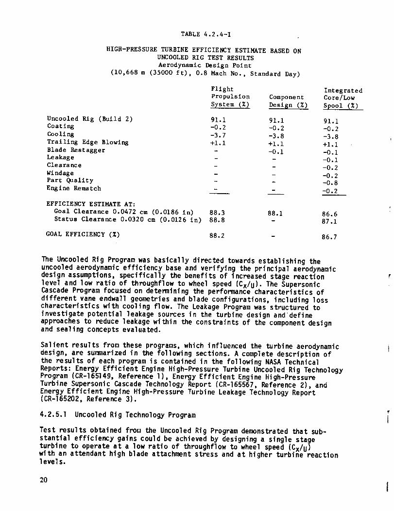
TABLE 4.2.4-I
HIGH-PRESSURE TURBINE EFFICIENCY ESTIMATE BASED ON
UNCOOLED RIG TEST RESULTS
Aerodynamic Design Point
(10,668 m (35000 ft), 0.8 Mach No., Standard Day)
Flight
Propuls ion Component
System (%) Design (%)
Uncooled Rig (Build 2) 91.1 91.1 91.1
Coating -0.2 -0.2 -0.2
Cooling -3.7 -3.8 -3.8
Trailing Edge Blowing +i. 1 +i. 1 +1.1
Blade Rest agger - -0.i -0.iLeakage - -0.1Clearance
- -0.2Wind age - -0.2Part Quality - - -0.8Engine Rematch - -0.2
EFFICIENCY ESTIMATE AT:
Goal Clearance 0.0472 cm (0.0186 in) 88.3
Status Clearance 0.0320 cm (0.0126 in) 88.8
GOAL EFFICIENCY (%)
88.1 86.6
- 87.1
88.2 - 86.7
IntegratedCore/Low
Spool (%)
The Uncooled Rig Program was basically directed towards establishing the
uncooled aerodynamic efficiency base and verifying the principal aerodynamic
design assumptions, specifically the benefits of increased stage reaction
level and low ratio of throughflow to wheel speed (Cx/U). The SupersonicCascade Program focused on determining the performance characteristics of
different vane endwa11 geometries and blade configurations, including losscharacteristics with cooling flow. The Leakage Program was structured to
investigate potential leakage sources in the turbine design and define
approaches to reduce leakage within the constraints of the component designand sealing concepts evaluated.
Salient results from these programs, which influenced the turbine aerodynamic
design, are summarized in the following sections. A complete description of
the results of each program is contained in the following NASA Technical
Reports: Energy Efficient Engine High-Pressure Turbine Uncooled Rig TechnologyProgram (CR-165149, Reference l), Energy Efficient Engine High-Pressure
Turbine Supersonic Cascade Technology Report (CR-165567, Reference 2), and
Energy Efficient Engine High-Pressure Turbine Leakage Technology Report(CR-165202, Reference 3).
4.2.5.1 Uncooled Rig Technology Program
Test results obtained from the Uncooled Rig Program demonstrated that sub-
stantial efficiency gains could be achieved by designing a single stage
turbine to operate at a low ratio of throughflow to wheel speed (Cx/U)with an attendant high blade attachment stress and at higher turbine reactionIevel s.
20
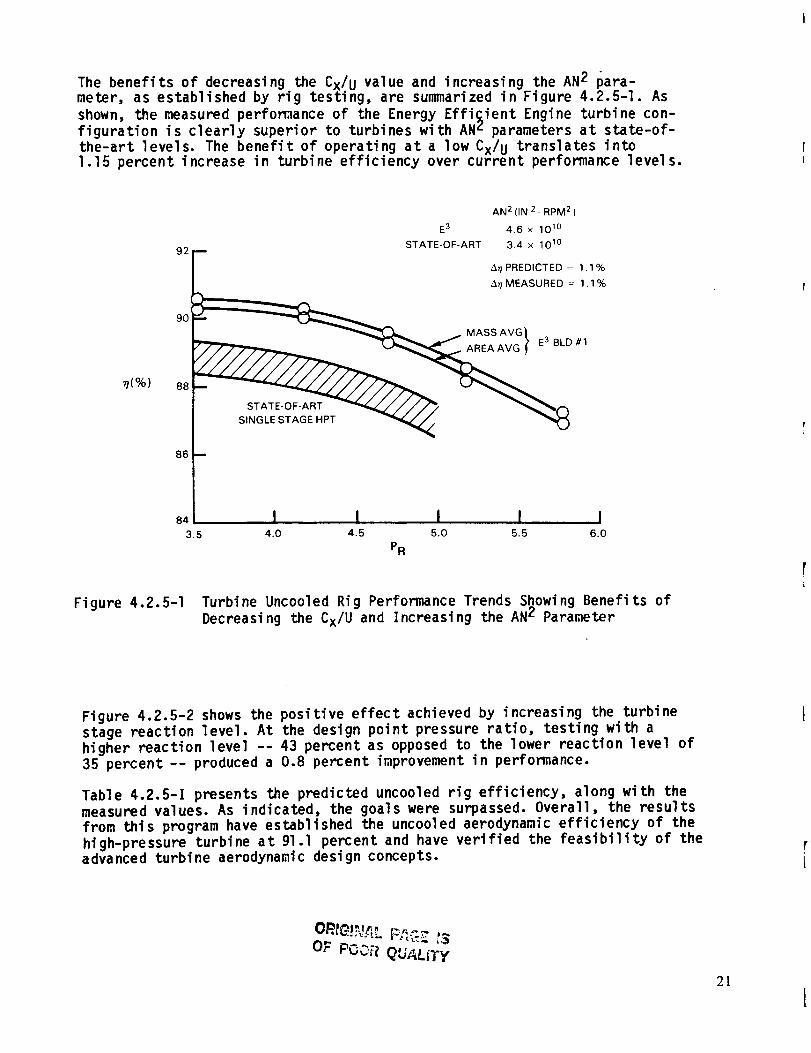
The benefits of decreasing the Cx/U value and increasing the AN2 para-meter, as established by rig testing, are summarized in Figure 4.2.5-1. As
shown, the measured perfomance of the Energy Effi£ient Engine turbine con-figuration is clearly superior to turbines with ANL parameters at state-of-the-art levels. The benefit of operating at a low Cx/u translates into1.15 percent increase in turbine efficiency over current performance levels.
7(%)
AN 2(IN 2_ RPM 2)
E3 4.6 x 101°
STATE-OF-ART 3.4 x 101°
92 1_ A_TPREDICTED = 1.1%/
_. A_ MEASURED = 1'1°//°
MASSAVGU/''_'` E3 BLD#1
SINGLE STAGE HPT _
86
84 I I I I I3.5 4.0 4.5 5.0 5.5 6.0
PR
Figure 4.2.5-I Turbine Uncooled Rig Performance Trends Showing Benefits of
Decreasing the Cx/U and Increasing the AN L Parameter
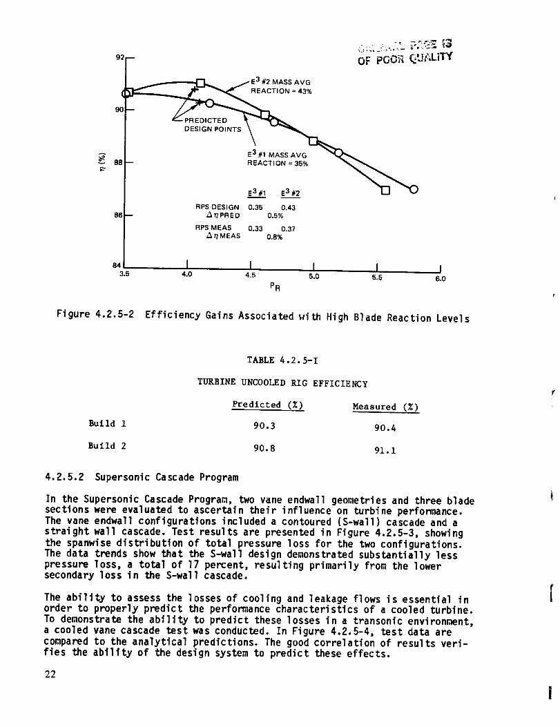
Figure 4.2.5-2 shows the positive effect achieved by increasing the turbine
stage reaction level. At the design point pressure ratio, testing with a
higher reaction level -- 43 percent as opposed to the lower reaction level of
35 percent-- produced a 0.8 percent improvement in performance.
Table 4.2.5-I presents the predicted uncooled rig efficiency, along with themeasured values. As indicated, the goals were surpassed. Overall, the results
from this program have established the uncooled aerodynamic efficiency of the
high-pressure turbine at gl.l percent and have verified the feasibility of theadvanced turbine aerodynamic design concepts.
OR_GI;_L PAGE t_
OF POOR QUALITy
21
92B OF PO0 QUt LITY
(
9O
3.5
_ E3 #2 MASS AVG
=43,
DESIGN POINTS _
E3 #1 MASS AVG
-- REACTI ON = 35% "_,_
E3 #1 E3 #2
RPS DESIGN 0.35 0.43A//PRED 0.5%
RPS MEAS 0.33 0.37AI,/MEAS 0.8%
I I I I I4.0 4.5 5.0 5.5 6.0
PR
Figure 4.2.5-2 Efficiency Gains Associated with High Blade Reaction Levels
TABLE 4.2.5-1
TURBINE UNCOOLED RIG EFFICIENCY
Predicted (%) Measured (%)
Build 1 90.3 90.4
Build 2 90.8 91.1
4.2.5.2 Supersonic Cascade Program
In the Supersonic Cascade Program, two vane endwall geometries and three blade
sections were evaluated to ascertain their influence on turbine performance.The vane endwall configurations included a contoured (S-wall) cascade and a
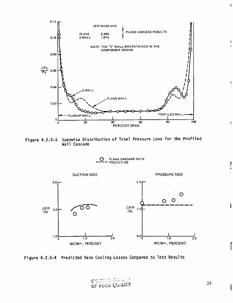
straight wall cascade. Test results are presented in Figure 4.2.5-3, showing
the spanwise distribution of total pressure loss for the two configurations.
The data trends show that the S-wall design demonstrated substantially less
pressure loss, a total of 17 percent, resulting primarily from the lowersecondary loss in the S-wall cascade.
The ability to assess the losses of cooling and leakage flows is essential inorder to properly predict the performance characteristics of a cooled turbine.
To demonstrate the ability to predict these losses in a transonic environment,a cooled vane cascade test was conducted. In Figure 4.2.5-4, test data are
compared to the analytical predictions. The good correlation of results veri-
fies the ability of the design system to predict these effects.
22
0.12
0.10
0.08
L_P/P MASS AVG
_> PLANE CASCADE RESULTSPLANE 2,34%
S WALL 1.91 %
NOTE: THE "S" WALL WAS RETAINED IN THE
COMPONENT DESIGN
0.06 _._t i l
o. RI _jr_/s WALL *I '. _:_'- " _PLANE WALL /(_/_ "_1_
0.02I_ --.\ ,,_- _#,01---- LA.A OF,L'DW'LL--"
0 20 40 60 80 100
PERCENT SPAN
Figure 4.2.5-3 Spanwise Distribution of Total Pressure Loss for the ProfiledWall Cascade
Figure
3,0
/kP/P 2.0-(%)
1.00
4.2.5-4
O PLANE CASCADE DATA.... PREDICTION
SUCTION SIDE
,,f(:T_-"O
I 12.01.0
WC/W°°, PERCENT
2.0
Ap/p 1.0(%)
0.0
Predicted Vane Cooling Losses Compared
PRESSURE SIDE
0
0 0
I I1.0 2.0
WC/W_ , PERCENT
to Test Results
OF FOCR _U:._Lri'Y23
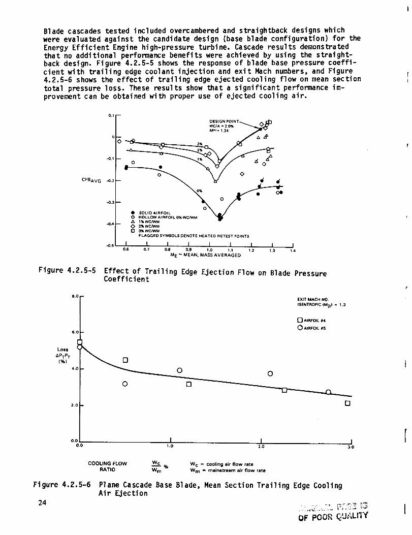
Blade cascades tested included overcambered and straightback designs whichwere evaluated against the candidate design (base blade configuration) for theEnergy Efficient Engine high-pressure turbine. Cascade results demonstrated
that no additional performance benefits were achieved by using the straight-
back design. Figure 4.2.5-5 shows the response of blade base pressure coeffi-
cient with trailing edge coolant injection and exit Mach numbers, and Figure4.2.5-6 shows the effect of trailing edge ejected cooling flow on mean section
total pressure loss. These results show that a significant performance im-
provement can be obtained with proper use of ejected cooling air.
0.1
-0.1
CPBAv G -O.2
-0.3
-0.4
-0.S
DESIGN POINT_ t%_)
WC/A - 2.0%
M °O- 1.24 f v
• SOLID AIRFOIL _ mJ
O HOLLOW AIRFOIL 0% WC/WM 1 _A t % WC/WM
O 2% WC/WM
n 3% WC/WM
FLAGGED SYMBOLS DENOTE HEATED RETEST POINTS
I I I I I I I I0.6 0.7 0.8 0.9 1,0 1.1 1.2 1.3
M E _ MEAN, MASS AVERAGED
I1.4
Figure 4.2.5-5 Effect of Trailing Edge Ejection Flow on Blade PressureCoefficient
8.0
6.0
Loss
_PTPT
(%)4.(
2.0
EXIT MACH NO.
ISENTROPIC (M2i) = 1.3
[_ AIRFOIL #4
0 AIRFOIL #5
D
0 0
O
o.o I I Io.o _.o 2.0 3.0
COOLING FLOW Wc_%
RATIO WmW c = cooling air flow rate
W m = mainstream air flow rate
Fi gure 4.2.5-6
24
Plane Cascade Base Blade, Mean Section Trailing Edge CoolingAir Ejection
OF POOR QUALITf

4.2.5.3 Leakage Program _l _ d _ _ l _ ._ _b P _ ....
The Leakage Program was conducted to evaluate techniques for leakage reductionin the high-pressure turbine. Based on this effort, the low leakage technologyin the Energy Efficient Engine high-pressure turbine has been successfullysubstantiated. Test models were used to simulate component leak paths as wellas to assess leakage reduction concepts. These nodels simulated the blade-diskattachment and the vane inner and outer platfom attachment seals.
The results of blade-disk attachment testing disclosed that leakage in this
area could be significantly reduced by paying careful attention to tolerances
along the contact surfaces between the vibration damper and platform contactsurface. As shown in Figure 4.2.5-7, attachment leakage is less than predicted,
thereby demonstrating the effectiveness of the blade dampers in sealing the
platforms.
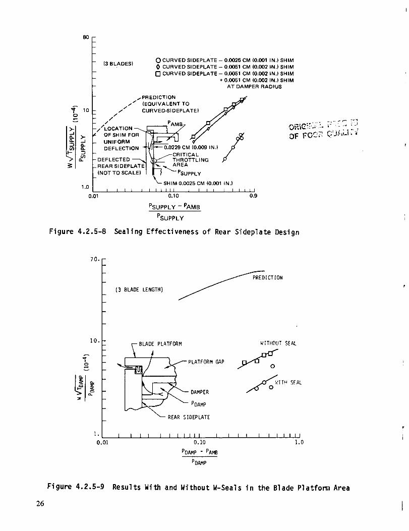
Other tests were conducted to verify the full ring sideplate, W-seal design.
The data presented in Figure 4.2.5-8 show that a flat rear sideplate againstthe disk face results in low leakage levels. Also, W-seals are effective in
controlling leakage, as indicated by the results in Figure 4.2.5-9.
80.0 -
- (4 DAMPERS)
TION
_-BLADE PLATFORM- 710.0 - \ /, BLADE GAP
- __/_t/__- OA.PER-
1 ,, - I FRONT LCONTACT POINT
Z_ VARIATIONS CAUSED- ¢ BY DAMPER
O0 INTERCHANGE
1.0 l l I l I I I I I I I I l l I I I I0.01 0.10 0.6
PDAMP - PAMB
PDAMP
Figure 4.2.5-7 Results of Blade-Disk Model Testing Showing Leakage in theAttachment Area is Less Than Predicted
25
A
,,¢!
o,I--
v
8O
10
>;,
1.0
0.01
- (3 BLADES)
-- /PREDICTION _"// (EQUIVALENT TO
/// CURVED-SIDEPLATE)
// PAMB r'_/
,'LOCATION 7 /-/"OF SHIM FOR "_ _ I 'El// '_
F_
UNIFORM ._ _ " _ 0" 7-
DEFLECTION -"_J _---"_.0229 CM (0.009 IN.) /
\ _CRITICAL JDEFLECTED -'_,,_ _ _____ THROTTLING /oREAR SIDEPLATE "__ ._ AREA
(NOT TO SCALE) "_ -_ PSUPPLY
k SHIM 0.(}025 CM (0.001 IN.)
0.10 0.9
PSUPPLY - PAMB
PSUPPLY
O CURVED SI DEPLATE - 0.0025 CM (0.001 IN.) SHIM
0 CURVED SIDEPLATE- 0.0051 CM (0.002 IN.)SHIM
O CURVED SIDEPLATE -0.0051 CM (0.002 IN.) SHIM
+ 0.0051 CM (0.002 IN.) SHIM
AT DAMPER RADIUS
Figure 4.2.5-8 Sealtng Effectiveness of Rear Sideplate Design
O
70. --
F
10.-
1.
0.01
(3 BLADE LENGTH) ICTION
BLADE PLATFORM PLATFORM--h/2L_'-____ REAR _i _DpAL_PTE
GAP
WITHOUT SEAL
I 1 I I 1 t I I 11 I I I I I 1 I I I I , I
0.10 1.0
PDAMP - PAMB
PDAMP
Figure 4.2.5-9 Results With and Without W-Seals in the Blade Platfom Area
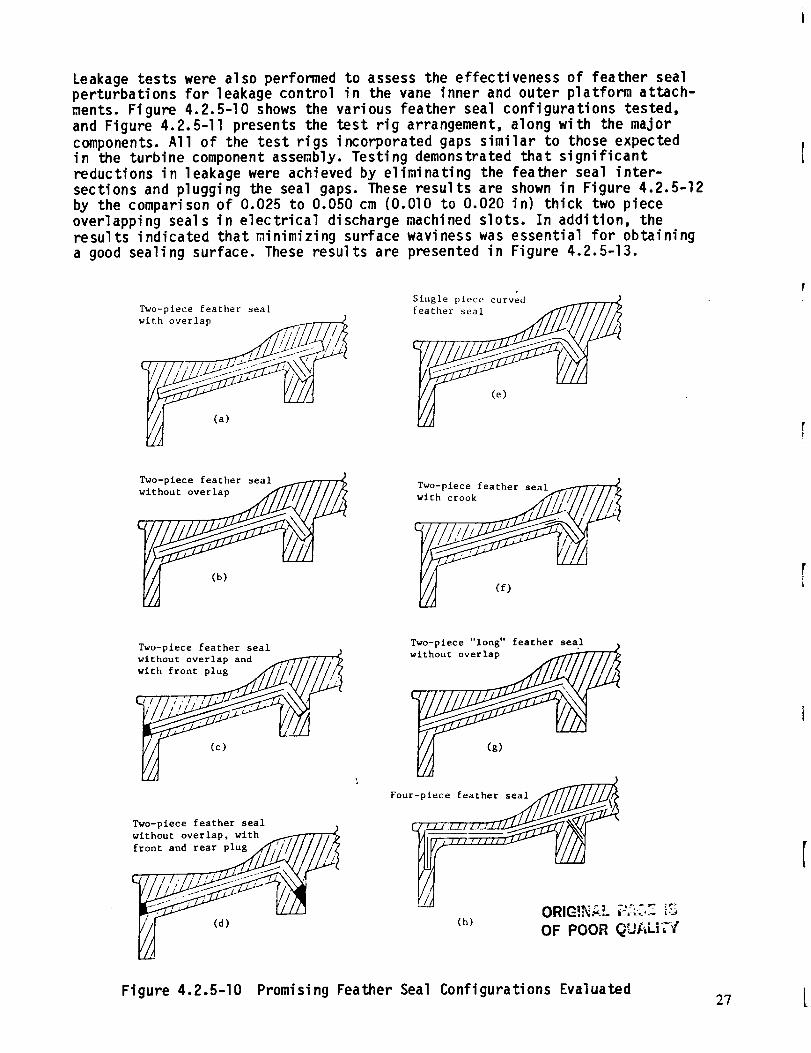
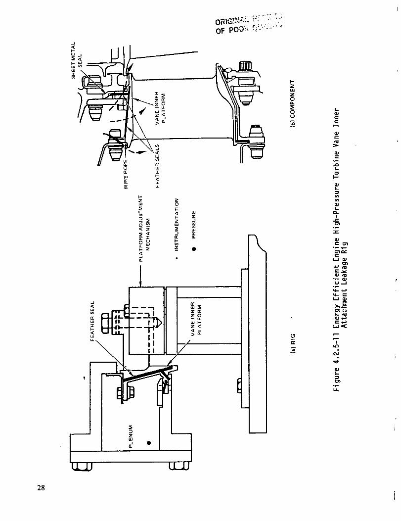
Leakage tests were also performed to assess the effectiveness of feather seal
perturbations for leakage control in the vane inner and outer platform attach-ments. Figure 4.2.5-I0 shows the various feather seal configurations tested,
and Figure 4.2.5-II presents the test rig arrangement, along with the major
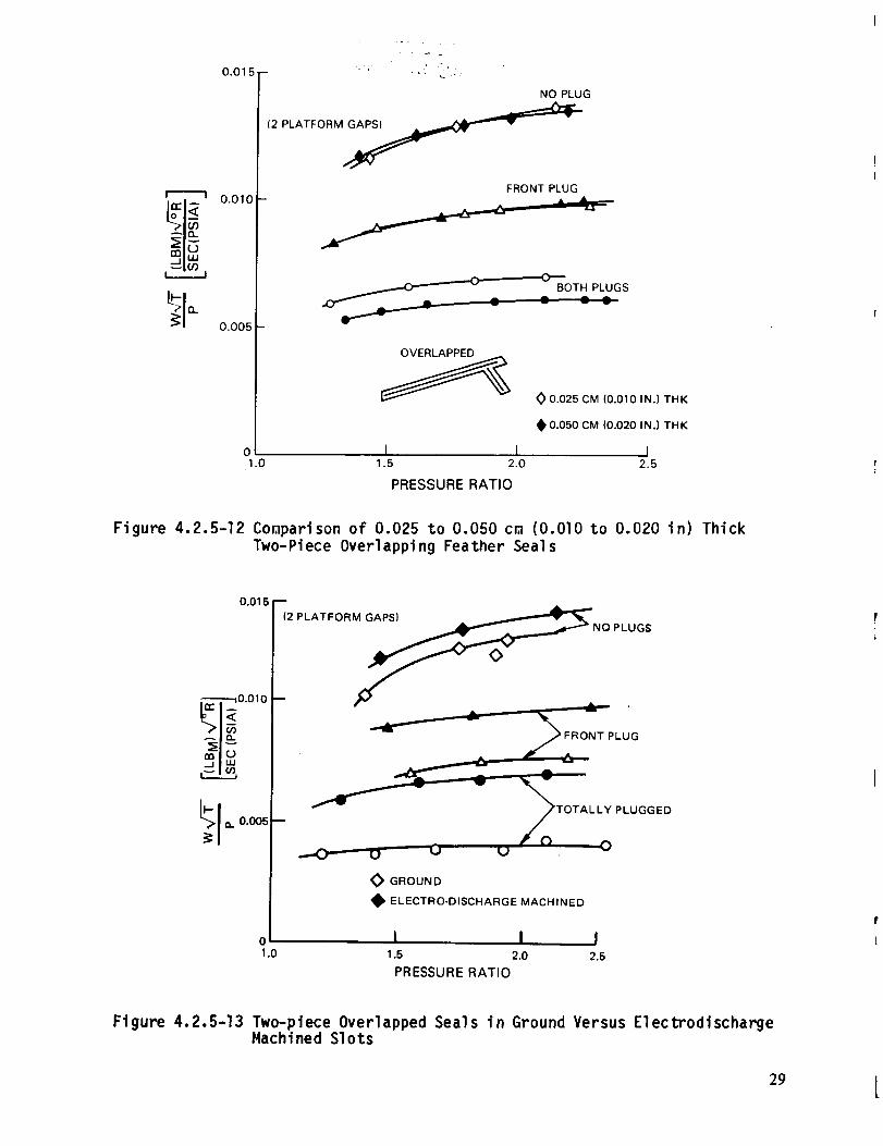
components. All of the test rigs incorporated gaps similar to those expectedin the turbine component assembly. Testing demonstrated that significant
reductions in leakage were achieved by eliminating the feather seal inter-
sections and plugging the seal gaps. These results are shown in Figure 4.2.5-12
by the comparison of 0.025 to 0.050 cm (O.OlO to 0.020 in) thick two piece
overlapping seals in electrical discharge machined slots. In addition, theresults indicated that minimizing surface waviness was essential for obtaining
a good sealing surface. These results are presented in Figure 4.2.5-13.
Two-piece feather seal
with overlap _
(a)
(e)
Two-piece feather seal
(b)
Two-plece feather seal_
Two-piece feather seal
without overlap and
(c)
Two-piece feather seal
without overlap, with _'_
front and re___ I
(d)
wT_thPuitCev'_rlOng" feather seal
F°u r-_ ie/_efla th/_
I I I I I I I I Fj'M_
ORIG!NAL ;:AC,._ _.":;;(h)
OF POOR QUALiT't
Figure 4.2.5-I0 Promising Feather Seal Configurations Evaluated27
.J
LIE
Z_J
tl.JJ
28
J
0.01!
0.01C
0.005 -
01.0
NO PLUG
(2 PLATFORM_
FRONT PLUG
j %_-
BOTH PLUGS
OVERLAPPED
I I1.5 2.0
_ 0.025 CM (0.010 IN.) THK
0.050 CM (0.020 IN.) THK
I2.5
PRESSURE RATIO
Figure 4.2.5-12 Conparison of 0.025 to 0.050 cm (0.010 to 0.020 in) Thick
Two-Piece Overlapping Feather Seals
0.015
0.010
N PLUGS
m
-- _TOTALLY PLUGGED
u O u O
GROUND
• ELECTRO-DISCHARGE MACHINED
o I I I1.0 1.5 2.0 2.5
PRESSURE RATIO
Figure 4.2.5-13 Two-piece Overlapped Seals in Ground Versus ElectrodischargeMachi ned S1ots
29 [
ORIGINAL PAGZ _
OF POOR QUALITY
SECTION 5.0
AIRFOIL DURABILITY
5.1 OVERVIEW
The Energy Efficient Engine high-pressure turbine design emphasizes operation
at a moderately high combustor exit temperature with a minimum of cooling to
maximize fuel efficiency. This must be achieved, however, with no compromise
in component durability.
Turbine airfoil durability goals for both vanes and blades are lO,O00 hours of
service life for the flight propulsion system and 50 hours hot section life at
28oc (84OF) day sea level takeoff conditions for the integrated core/low
spool. The lO,O00 hour goal is established in terms of international missions,
and reflects an equivalent of 2200 missions. These goals are achieved through
the combination of improved cooling effectiveness and advanced high-temperature
capability materials.
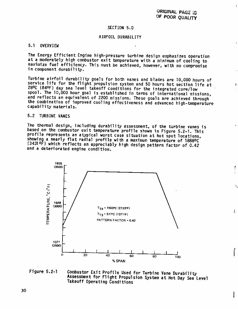
5.2 TURBINE VANES
The themal design, including durability assessment, of the turbine vanes is
based on the combustor exit temperature profile shown in Figure 5.2-I. This
profile represents an atypical worst case situation at hot spot locations,
showing a nearly flat radial profile with a maximum temperature of 1888oc
(3431OF) which reflects an appreciably high design pattern factor of 0.42
and a deteriorated engine condition.
1926
(3500)
_Jo
o:: 164B:::)I.- (300O)
TT4 = 1500=C (2733"F)
n..",,, TT3 = 577oC (1071OF)a..
PATTERN FACTOR = 0.42LLI
I-
1371
(2500)
i I l l I i I J0 20 40 60 80 1O0
% SPAN
Figure 5.2-I Combustor Exit Profile Used for Turbine Vane DurabilityAssessment for Flight Propulsion System at Hot Day Sea Level
Takeoff Operating Conditions
30 I
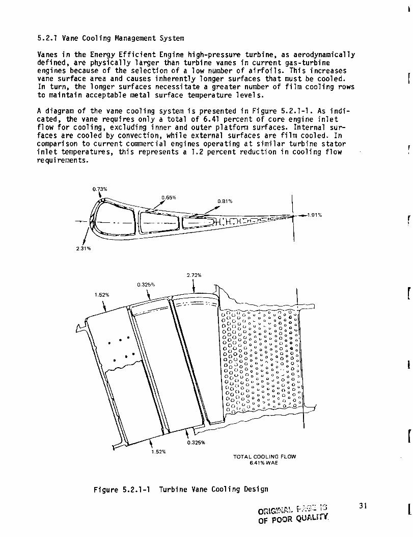
5.2.1 Vane Cooling Management System
Vanes in the Energy Efficient Engine high-pressure turbine, as aerodynamicallydefined, are physically larger than turbine vanes in current gas-turbine
engines because of the selection of a low number of airfoils. This increases
vane surface area and causes inherently longer surfaces that must be cooled.
In turn, the longer surfaces necessitate a greater number of film cooling rows
to maintain acceptable metal surface temperature levels.
A diagram of the vane cooling system is presented in Figure 5.2.1-I. As indi-
cated, the vane requires only a total of 6.41 percent of core engine inlet
flow for cooling, excluding inner and outer platform surfaces. Internal sur-
faces are cooled by convection, while external surfaces are film cooled. In
comparison to current commercial engines operating at similar turbine stator
inlet temperatures, this represents a 1.2 percent reduction in cooling flow
requirements.
0.73%
2.31%
.91%
1.52%
0.325%
2.72%
1.52%
0.325%
TOTAL COOLING FLOW6.41% WAE
Figure 5.2.1-I Turbine Vane Cool ing Design
O_IG_..',_, F.;_ _3OF POOR QUt,_LiTY.
31
Cooling air enters the vane from the tip and the root at a pressure of2,840,657 Pa (412 psia) and temperature of 577oC (1071OF) at the
durability design condition of sea level takeoff, hot day. Exact percentages
of flow are depicted in Figure 5.2.1-I. The coolant is distributed within the
internal structure of the vane, which is designed with three cavities. These
cavities are convectively cooled through the use of sheet metal impinge_nt
tubes that fit into the three cavities. To provide maximum strength against
bulging deformation, two ribs tie the pressure wall and suction wall to-
gether. In addition, the vane trailing edge is convectively cooled by cooling
air flowing through a series of pedestals or braces between the vane walls.
Cooling flow passes around the pedestals and is discharged through a slot in
the trai Iing edge.
The front cavity impingement tube is supplied cooling air to convectively coolthe walls of the cavity. After the internal surface is cooled, the coolant is
discharged through an array of showerhead holes in the leading edge as well as
a set of holes downstream of the leading edge on the suction wall to provide a
cooling film over the external surface. The showerhead holes are angledradially, as opposed to the axial angular orientation of the film cooling
holes on the suction and pressure walls, for more effective heat transfer in
the thick leading edge region.
The middle and rear cavities also contain impingement tubes from which
numerous cooling air jets are impinged against the vane inside surface.
Cooling air flows in a chordwise direction and is discharged through axially-
angled film holes in order to provide film cooling. A portion of the cooling
air in the rear cavity is channeled through the trailing edge pedestal and
discharged at the vane trailing edge. The size and spacing of the pedestals
have been selected to provide the desired convective cooling and cooling flowlevel s.
Because of the somewhat unusual aerodynamic contour of the vane, the stag-
nation point on the airfoil appears on the pressure surface. This surface is
film cooled to offset this heat load by two sets of two rows of holes, approxi-
mately 0.058 cm (0.023 in) in diameter. The suction surface incorporates threerows of cooling holes, approximately 0.050 cm (0.020 in) in diameter.
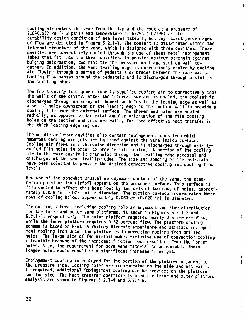
The cooling scheme, including cooling hole arrangement and flow distribution
for the inner and outer vane platforms, is shown in Figures 5.2.1-2 and
5.2.1-3, respectively. The outer platform requires nearly 0.5 percent flow,
while the inner platform requires 0.32 percent flow. The platform cooling
scheme is based on Pratt & Whitney Aircraft experience and utilizes impinge-
ment cooling from under the platform and convection cooling from drilled
holes. The large size of fhe airfoil makes exclusive use of convection cooling
infeasible because of the increased friction loss resulting from the longer
holes. Also, the requirement for more vane material to accommodate these
longer holes would result in a significant increase in weight.
Impingement cooling is employed for the portion of the platform adjacent tothe pressure side. Cooling holes are incorporated on the side and aft rails.
If required, additional impingement cooling can be provided on the platform
suction side. The heat transfer coefficients used for inner and outer platformanalysis are shown in Figures 5.2.1-4 and 5.2.1-5.
32
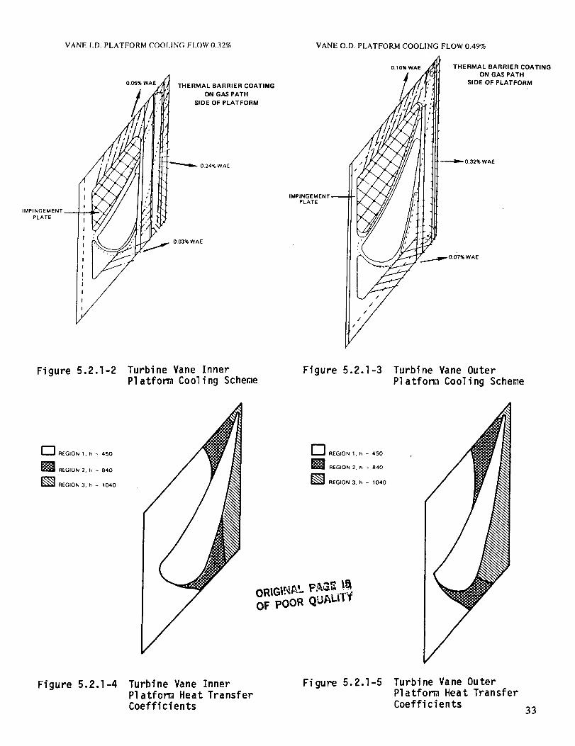
VANE I.D. PLATFORM COOLING FLOW 0.32% VANE O.D. PLATFORM COOLING FLOW 0.49%
0.05% WAETHERMAL BARRIER COATING
ON GAS PATH
SIDE OF PLATFORM
0.10% WAE THERMAL BARRIER COATING
ON GAS PATH
SIDE OF PLATFORM
0.32% WAE
IMPINGEMENT
PLATE
PLATE
0,03% WAE
Figure 5.2.1-2 Turbine Vane InnerPlatfom Cooling Scheme
Figure 5.2.1-3 Turbine Vane Outer
Platfom Cooling Scheme
_'l REGION 1. h - 450
[]REGION 2, h _ 840
_ REGION 3, h - 1040
F_ REGION 1, h - 4,50
] REGION 2, h - 840
L_ REGION 3. h ~ 1040
OF poOR QUAL|TIf
Figure 5.2.1-4 Turbine Vane InnerPlatforg Heat Transfer
Coefficients
Figure 5.2.1-5 Turbine Vane Outer
Platform Heat Transfer
Coefficients33
An assessment of the effectiveness of the vane cooling management system issummarized in Figures 5.2.1-6 through 5.2.1-10. The effectiveness of the filmover the long suction wall is compared to two-dimensional flow on a flat platein Figure 5.2.1-6. As shown, the Energy Efficient Engine design is conserva-tive relative to the flow on a flat plate. Results of a themal analysis,using the combustor exit profile shown in Figure 5.2-1, are presented inFigure 5.2.1-7. As shown by this isothem plot, the highest calculated metaltemperature is 1226oc (2239OF) on the suction side wall adjacent to thethird cavity.
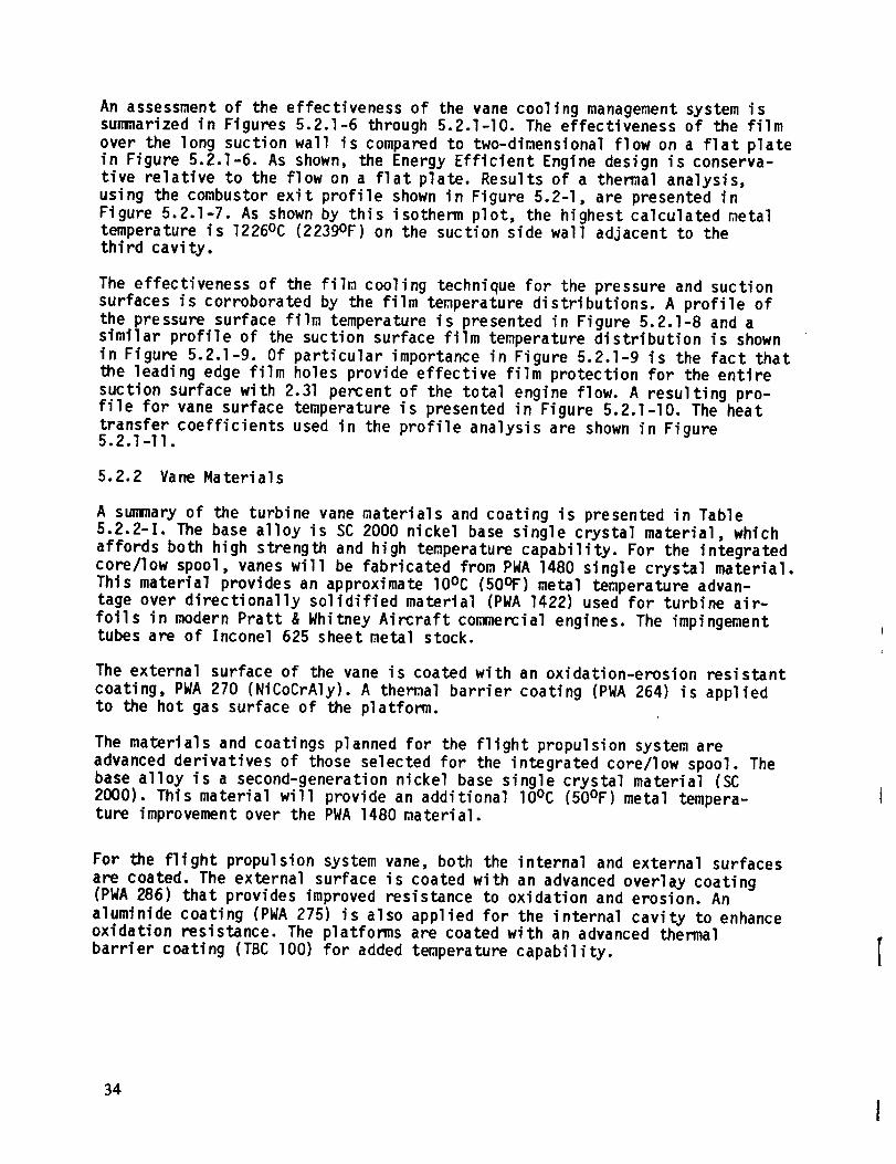
The effectiveness of the film cooling technique for the pressure and suctionsurfaces is corroborated by the film temperature distributions. A profile ofthe pressure surface film temperature is presented in Figure 5.2.]-8 and asimilar profile of the suction surface film temperature distribution is shownin Figure 5.2.1-9. Of particular importance in Figure 5.2.1-9 is the fact thatthe leading edge film holes provide effective film protection for the entiresuction surface with 2.31 percent of the total engine flow. A resulting pro-file for vane surface temperature is presented in Figure 5.2.1-10. The heattransfer coefficients used in the profile analysis are shown in Figure5.2.1-II.
5.2.2 Vane Materials
A summary of the turbine vane materials and coating is presented in Table
5.2.2-I. The base alloy is SC 2000 nickel base single crystal material, which
affords both high strength and high temperature capability. For the integrated
core/low spool, vanes will be fabricated from PWA 1480 single crystal material.
This material provides an approximate lOOC (50OF) metal temperature advan-tage over directionally solidified material (PWA 1422) used for turbine air-
foils in modern Pratt & Whitney Aircraft commercial engines. The impingementtubes are of Inconel 625 sheet metal stock.
The external surface of the vane is coated with an oxidation-erosion resistant
coating, PWA 270 (NiCoCrAly). A themal barrier coating (PWA 264) is appliedto the hot gas surface of the platform.
The materials and coatings planned for the flight propulsion system are
advanced derivatives of those selected for the integrated core/low spool. Thebase alloy is a second-generation nickel base single crystal material (SC
2000). This material will provide an additional lOOC (50OF)metal tempera-ture improvement over the PWA 1480 material.
For the flight propulsion system vane, both the internal and external surfaces
are coated. The external surface is coated with an advanced overlay coating(PWA 286) that provides improved resistance to oxidation and erosion. An
aluminide coating (PWA 275) is also applied for the internal cavity to enhanceoxidation resistance. The platforms are coated with an advanced thermal
barrier coating (TBC lO0) for added temperature capability.
34

TG-T F
TG-T C
0°8 m
0.6 --
0.5
0.4 --
0.3 --
0.2 --
0.1
4O
I I I I I 160 80 100
T G = TEMPERATURE, GAS STREAM
T F = TEMPERATURE, FILM
T C = TEMPERATURE, COOLANT SUPPLY
CURRENT DESIGNS
%" '_' % %%'%"
. /,%
%
EEE EXTRAPOLATION /
OF F oo'_
200
S/D FROM STAGNATION PT.
2-D FLOW ON PLATE
%,
%,
S = SURFACE DISTANCE FROM
STAGNATION POINT
D = COOLING HOLE DIAMETER
1 I I I I I I400 600 800
Figure 5.2.1-6 Suction Surface FilD Effectiveness
1010 (1850)
1093 (2000)
954 (1750)
1148 (2100)
1226(2239)
1148 (2100)
°C(°F)982 (1800)
176 (2150)
1176 (2150)
1176 (2150)
1176 (2150)
Figure 5.2.1-7 Vane Themal Analysis Results35
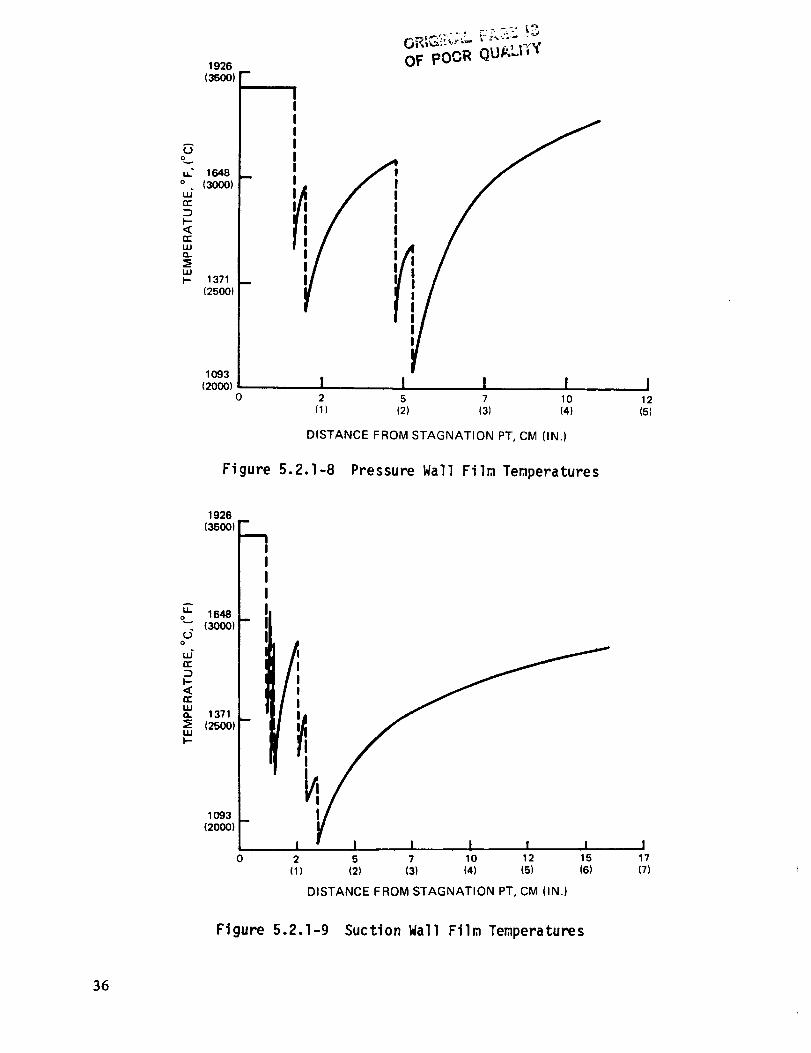
1926m
(3500)
(..)o
u..." 1648 _o (3000)
UJ
nr
I.--<n-uJQ,.
LUI-- 1371 --
(25OO)
1093
(200O)0
OF poOR QU/_LFIY
!2
(1)
I
VI I I5 7 10
(2) (3) (4)
DISTANCE FROM STAGNATION PT, CM (IN.)
Figure 5.2.1-8 Pressure Wall Film Temperatures
I12
(5)
A
u. 1648o
(3000)d
o
n--:Z)I--<(
LUO. 1371
(2500)uJI-
1926m
(350O)
"---I
/,:
1093
12000)
i0 2
(1)
I I I I I5 7 10 12 15
(2) (3) (4) (5) (6)
DISTANCE FROM STAGNATION PT, CM (IN.)
I17
(7)
Figure 5.2.1-9 SuctionWall Film Temperatures
36
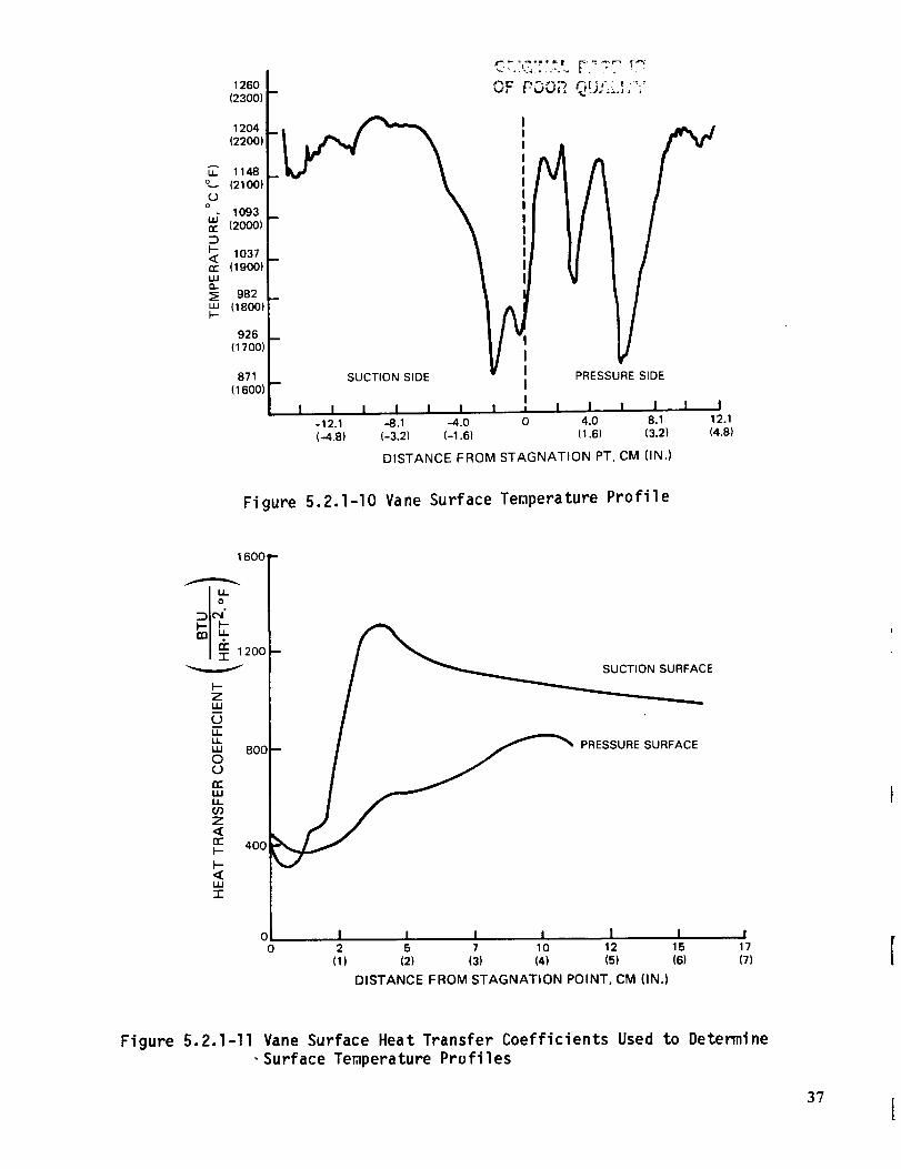
1260
(23O0)
1204
(2200)
o_ 1148(21001
°_ 1093
_ 120001
_ 1037
119001
uJa._; 982,,I 118001F-
926
117001
871
(1600)SUCTION SIDE
I I I
-12.1 -8.1
(-4.8) (-3.2)
kI I I = I I I I I I
-4.0 0 4.0 8.1 17.1
(-1.6) (1.6) (3.2) (4.8)
F
PRESSURE SIDE
DISTANCE FROM STAGNATION PT, CM (IN.)
Figure 5.2.1-I0 Vane Surface Temperature Profile
SUCTION SURFACE
PRESSURE SURFACE
I I I I I I I2 5 7 10 12 15 17
(1) (2) (3) (4) (5) (6) (7)
DISTANCE FROM STAGNATION POINT, CM (IN.)
Figure 5.2.1-II Vane Surface Heat Transfer Coefficients Used to Determine
-Surface Temperature Profiles
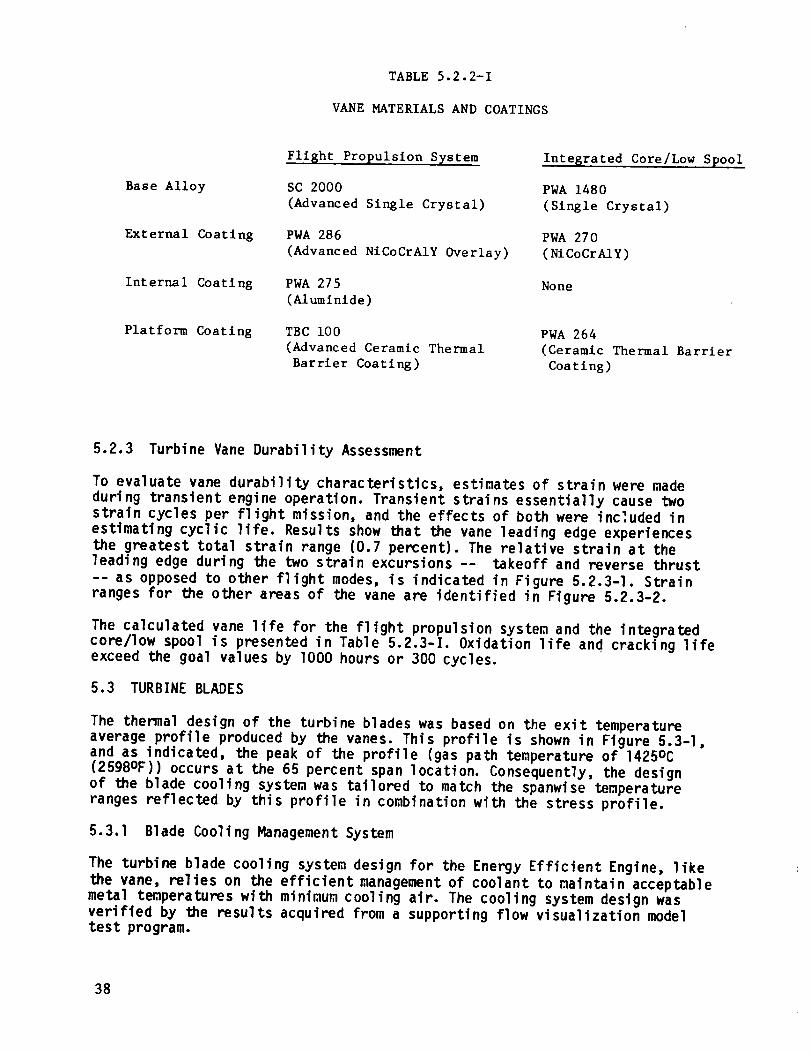
TABLE 5.2.2-1
VANE MATERIALS AND COATINGS
Base Alloy
External Coating
Internal Coating
Platform Coating
Flight Propulsion System
SC 2000
(Advanced Single Crystal)
PWA 286
(Advanced NiCoCrAIY Overlay)
PWA 275
(Aluminlde)
TBC i00
(Advanced Ceramic Thermal
Barrier Coating)
Integrated Core/Low Spool
PWA 1480
(Single Crystal)
PWA 270
(NiCoCrAIY)
None
PWA 264
(Ceramic Thermal Barrier
Coating)
5.2.3 Turbine Vane Durability Assessment
To evaluate vane durability characteristics, estimates of strain were madeduring transient engine operation. Transient strains essentially cause twostrain cycles per flight mission, and the effects of both were inc_.uded inestimating cyclic life. Results show that the vane leading edge experiencesthe greatest total strain range (0.7 percent). The relative strain at theleading edge during the two strain excursions -- takeoff and reverse thrust-- as opposed to other flight modes, is indicated in Figure 5.2.3-1. Strainranges for the other areas of the vane are identified in Figure 5.2.3-2.
The calculated vane life for the flight propulsion system and the integratedcore/low spool is presented in Table 5.2.3-I. Oxidation life and cracking lifeexceed the goal values by lO00 hours or 300 cycles.
5.3 TURBINE BLADES
The thermal design of the turbine blades was based on the exit temperatureaverage profile produced by the vanes. This profile is shown in Figure 5.3-I,
and as indicated, the peak of the profile (gas path temperature of 1425oc
(2598OF)) occurs at the 65 percent span location. Consequently, the design
of the blade cooling system was tailored to match the spanwise temperature
ranges reflected by this profile in combination with the stress profile.
5.3.1 Blade Cooling Management System
The turbine blade cooling system design for the Energy Efficient Engine, like
the vane, relies on the efficient management of coolant to maintain acceptable
metal temperatures with minimum cooling air. The cooling system design was
verified by the results acquired from a supporting flow visualization model
test program.
38
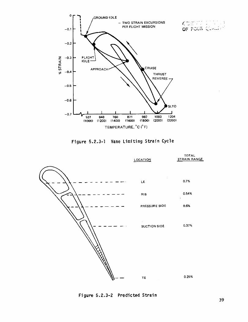
0 ¸
-0.1
-0.2
Z -0.3
<CEI--o_
--0.4
--0.5
-0.6
II
FLIGHT
IDLE
TWO STRAIN EXCURSIONS
PER FLIGHT MISSION
APPROACF
IDLE
\
V537 648 760 871
(1000) (1200) (1400) (1600)
CRUISE
THRUST
REVERSE
;LTO
982 1093 1204
(1800) (2000) (2200)
TEMPERATURE, °C (o F)
OF T,3L:T, _;_,-,.,;.
Figure 5.2.3-I Vane Limiting Strain Cycle
LOCATION
TOTAL
STRAIN RANGE
LE 0.7%
RIB 0.54%
PRESSURE SIDE 0.6%
SUCTION SIDE 0.37%
TE 0.25%
Figure 5.2.3-2 Predicted Strain
39
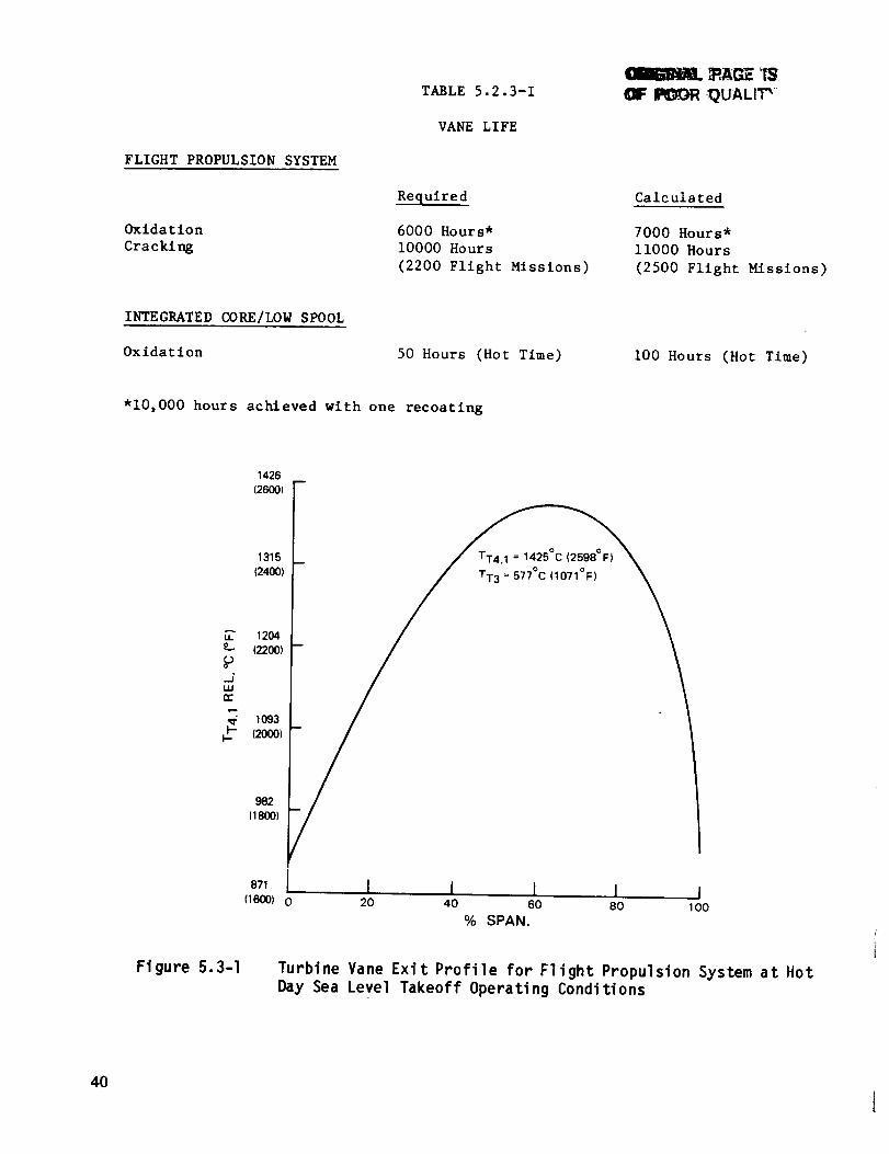
FLIGHT PROPULSION SYSTEM
Oxidation
Cracking
TABLE 5.2.3-1
VANE LIFE
Required
6000 Hours*
I0000 Hours
(2200 Flight Missions)
P,AGE I$
II_ ._UALI_ "_
Calculated
7000 Hours*
ii000 Hours
(2500 Flight Missions)
INTEGRATED CORE/LOW SPOOL
Oxidation 50 Hours (Hot Time) i00 Hours (Hot Time)
*i0,000 hours achieved with one recoating
1426(2600)
1315
(2400)
_" 1204o (2200)
_j"uJn,-
1093I-'- (2000)I--
982(18OO)
TT4.1 = 1425°C (2598°F)
TT3 = 577°C (1071°F)
Fi gure 5.3-I
I I I I I20 40 60 80 1O0
% SPAN.
Turbine Vane Exit Profile for Flight Propulsion System at Hot
Day Sea Level Takeoff Operating Conditions
40
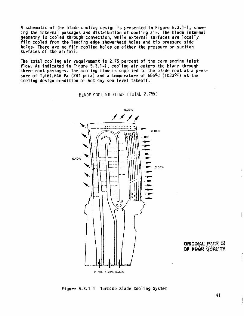
A schematic of the blade cooling design is presented in Figure 5.3.1-1, show-ing the internal passages and distribution of cooling air. The blade internalgeometry is cooled through convection, while external surfaces are locallyfilm cooled from the leading edge showerhead holes and tip pressure sideholes. There are no film cooling holes on either the pressure or suctionsurfaces of the airfoil.
The total cooling air requirement is 2.75 percent of the core engine inlet
flow. As indicated in Figure 5.3.1-I, cooling air enters the blade through
three root passages. The cooling flow is supplied to the blade root at a pres-
sure of 1,661,646 Pa (241 psia) and a temperature of 556°C (I033°F) at the
cooling design condition of hot day sea level takeoff.
BLADE COOLING FLOWS (TOTAL 2.75%)
0.40%
0.26%
///#
0.04%
0.70% 1.72% 0.33%
2.05%
ORIG!NA= PAC 7.OF
Figure 5.3.1-I Turbine Blade Cooling System
4]

The front passage supplies approximately 25 percent of the total blade flow to
cool the leading edge and tip. This flow is discharged through a series of0.038 to 0.050 cm (0.015 to 0.020 in) diameter showerhead holes at the leading
edge and an array of 0.050 to 0.063 cm (0.020 to 0.025 in) diameter holes at
the tip. Since the predicted gas temperatures are substantially lower at the
airfoil span extremes, as shown earlier in Figure 5.3-I, the leading edge
cooling hole pattern has been tailored to accor._odate these temperature re-
quirements. In addition, trip strips are integral with the internal passage
design to promote a higher heat transfer rate.
The middle passage utilizes approximately two-thirds of the total blade cool-
ing flow. Flow circulates through the internal cavity, making two spanwise
excursions, and enters the trailing edge passage where it passes through anarray of pedestals before being discharged into the gas path. Trip strips are
also used in the passages to raise the heat transfer coefficient. At the tip
and root sections, turning vanes are used to reduce aerodynamic flow separa-tion and the attendant pressure loss penalty. Sizing of the flow areas was
carefully selected to avoid areas of diffusion that could lead to flow separa-tion and high pressure loss.
The third blade passage directs a small percentage of cooling air to cool aportion of the root area and supplements trailing edge cooling. Flow injection
improves the flow distribution in the root turn area with essentially nopenalty on the cooling supply pressure.
Verification of the coolant passage design was accomplished by the use of a
five times size flo_ model (Reference 4), which duplicated the conpleteinternal shape of the blade.
The capability of the cooling system design to maintain acceptable metal tem-
peratures was confirmed by a thermal analysis. Figure 5.3.1-2 presents an
isotherm plot of the blade laid-span section. As indicated, the average metal
temperature is 954oC (1750OF). The highest predicted temperature isslightly above I093oc (2000OF), and occurs on the suction wall surface
near the first rib. A profile of pressure and suction surface temperatures is
shown in Figure 5.3.1-3. The heat transfer coefficients used in the profileanalysis are shown in Figure 5.3.1-4.
5.3.2 Blade Materials
A summary of the materials and coatings selected for the turbine blade is
presented in Table 5.3.2-I for the integrated core/low spool and flight pro-
pulsion system. For both applications, the base material and coatings are thesame as for the turbine vane. The base material is an advanced nickel base
single crystal alloy and the blade is coated with an advanced oxidation
resistant coating. The major difference is that a thermal barrier coating onthe platfom is not required.
42
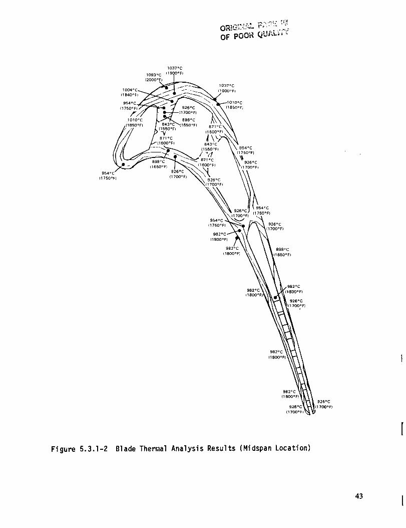
OF pOOR QUAL_'_r'_
(1800°F)
982°C 898oc
(1800°FI 11650OF)
1982°C
982°( 1800OFI(1800°F
926°C
,(1700°F}
982°C
(1800°F
Fi gure 5,3,1-2
982°C
(1800°F)
926°C
(1700°F)
Blade Thermal Analysis Results (Midspan Location)
926°C
i(1700°F)
43 l
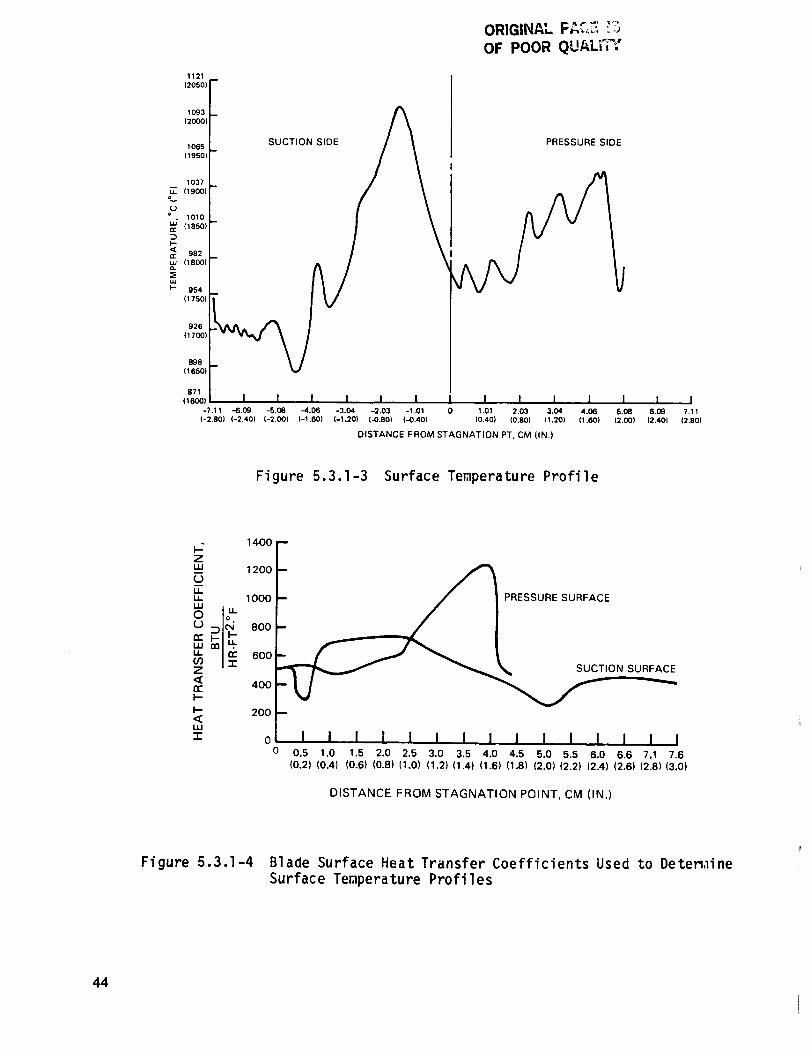
ORIGINAL F,_,C.7_!_
OF POOR QUALi"_:
1121
(2050) F
1093
(2OOO)
1065 ;
(1950)
SUCTION SIDE PRESSURE SIDE
1037
_ (1900)
=v
o. 1010
(18501
DI,-
_ 982
LU 118001
LU
I'- 954
(1750l
926
(1700)
898
(165Ol
871
(1600)_
-7.11 -6.09 -5.08 -4.06 -3.04 -2.03 -1.01
(-2.80) (-2.40) (-2.00) (-1.60) (-1.20) (-0.80) (-0.40)
I I I I I I I1,01 2,03 3,04 4.06 5.08 6.09 7.11
(0.40) (0.80) (1.20) (1.60) (2.00) (2.401 (2.80)
DISTANCE FROM STAGNATION PT. CM (IN.)
Figure 5.3.1-3 Surface Temperature Profile
1400Z-- 1200 --
LuU" 10OO-- / I PRESSURE SURFACE
°21C C IL) ' 800 --
u_ 600 -- _(/3Z _ _ _ SUCTION SURFACE
I--
<_I-- 200UJ
-r o I I I l I l I I I I I I I I I IO 0.5 1.0 1.5 2.0 2.5 3.0 3.5 4.0 4.5 5.0 5.5 6.0 6.6 7.1 7.6
{0.2) (0.4) (0.6) (0.8) (1.0) (1.2) (1.4) (1.6) (1.8) (2.0) (2.2) (2.4) (2.6) (2.8) (3.0)
DISTANCE FROM STAGNATION POINT, CM (IN.)
Figure 5.3.1-4 Blade Surface Heat Transfer Coefficients Used to Deten,line
Surface Temperature Profiles
44

TABLE 5.3.2-1
BLADE MATERIALS
Base Alloy
External Coating
Internal Coating
Flisht Propulslon System
SC 2000
(Advanced Single Crystal)
PWA 286
(Advanced NiCoCrAIY)
PWA 275
(Aluminide)
Intesrated Core/Low Spool
PWA 1480
(Single Crystal)
PWA 270
(NiCoCrAIY)
None
5.3.3 Turbine Blade Durability Assessment
An analysis of transient strains encountered during the flight cycle resulted
in predicted lives that meet the durability goals. Characterization of blade
strain properties showed that the first rib is subjected to the highest strain(0.55 percent range). Rib strain as a function of flight mode and corresponding
operating temperature is shown in Figure 5.3.3-I. Strain ranges for otherparts of the blade are indicated in Figure 5.3.3-2.
z"<_r
03
0.6,
05
04
0.3
0.2
0.1
(COLD RIB)
-- _ SLTO
_ f/ i]CRUISE
TWO STRAIN EXCURSIONSPER FLIGHT MISSION
-- GROUNDI
_- FLIGHT _-- I IDLE!
!!
o --J ,vl I I I I I I0 426 537 648 760 871 982 1093
(800) (1000) (1200) (1400) (1600) (1800) (2000)
TEMPERATURE, °C (OF)
Figure 5.3.3-I Blade Limiting Strain Cycle
45

LOC.
RIB
TOTAL
STRAIN RANGE
0.55%
L.E. 0.28%
PRESSURE SIDE 0.25%
SUCTION SIDE 0.37%
T.E. 0.27%
Figure 5.3.3-2 Predicted Strain
The calculated blade life for oxidation and cracking failure modes is tabula-
ted in Table 5.3.3-I. Durability goals for both the integrated core/low spool
and flight propulsion system are surpassed by an appreciable margin, as shownby these results. Cracking as a result of creep is defined as the life limit-
ing failure mode. Figure 5.3.3-3 presents the calculated blade temperatures.
FLIGHT PROPULSION SYSTEM
TABLE 5.3.3-I
BLADE LIFE
Oxidation
Cracking*
Required
6,000 Hours
I0,000 Hours
(2200 Flight Missions)
Calculated
16,000 Hours
16,000 Hours
(3500 Flight Missions)
INTEGRATED CORE/LOW SPOOL
Oxidation
Creep
50 Hours (Hot Time)
50 Hours (Hot Time)400 Hours (Hot Time)
80 Hours (Hot Time)
*Cracking due to interacting creep and low cycle fatigue
46
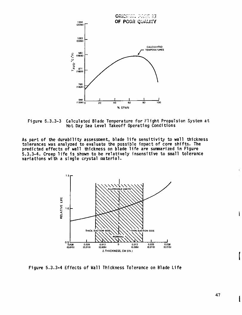
12O4
(22OO1
1093
12000)
982
o_ (1800)
_ 871(16001
760
(1400)
OF POOR QL_AL|TI
B
CALCULATED
f TEMPERATURES
e4e I I I I I11200) 0 20 40 60 80 100
% SPAN
Figure 5.3.3-3 Calculated Blade Temperature for Flight Propulsion System at
Hot Day Sea Level Takeoff Operating Conditions
As part of the durability assessment, blade life sensitivity to wall thicknesstolerances was analyzed to evaluate the possible impact of core shifts. The
predicted effects of wall thickness on blade life are summarized in Figure
5.3.3-4. Creep life is shown to be relatively insensitive to small tolerance
variations with a single crystal material.
.J
uJ
_> 1.oi-
5
O,_ _
0.038
10.015)
1.5 m
4
' \\\\_\\\ '/
B
T_ON SIDE_ _ _r_ _ _ "" THIN SUCTION SIDE
•, , ,0.025 0.012 0 0.012 0.025 0.038
(0.01 O) (0.005) (0.005l (0.010) i0.015l
THICKNESS, CM (IN.)
Figure 5.3.3-4 Effects of Wall Thickness Tolerance on Blade Life
47
I
SECTION 6.0
SECONDARY AIRFLOW SYSTEM
6.1 OVERVIEW
The high-pressure turbine secondary flow system is designed to maximize theuse of secondary air for cooling and thrust balance as well as minimize para-
sitic leakage and the attendant performance penalty. The primary design fea-
tures that enhance leakage control and contribute to a higher overall systemperforuance incl ude:
A tangential on-board injection (TOBI) system for positive bladecoolant flow supply
Front rim cavity mini tangential on-board injection (TOBI) system
Boltless and full ring rotor sideplates
A multi knife-edge, stepped high-pressure compressor discharge seal.
The benefits derived from these features, in conjunction with improved sealing
concepts, result in the utilization of only 14.10 percent of the core engineinlet flow for cooling the high-pressure turbine disk, blades, vanes and case
in the flight propulsion system.
Much of the sealing technology incorporated in the secondary flow system
design has evolved from a leakage supporting technology program. This effort
was instrumental in providing design guidance for the vane feather seals,
blade damper seals and outer air seal. Significant results from the leakageprogram are described in Section 4.2.5.3.
6.2 SECONDARY FLOW SUMMARY
Figure 6.2-I shows a secondary flow map of the high-pressure turbine, identi-
fying cooling air flows, secondary cooling flows, leakage flow rates, and the
static pressure at various points. Table 6.2-I presents a status sugary of
the flow rates of the major turbine components in both the flight propulsion
system and integrated core/low spool. Secondary flow totals for the flight
propulsion system and integrated core/low spool are 14.10 and 14.56 percent ofthe total inlet flow, respectively. The slight difference in total flow is
based on the assumption that the flight propulsion system will incorporate ahigher level of feather seal technology in the vane and outer seals. These
numbers differ from those shown for Wc/a in Table 3.3-I since they arestatus numbers and represent flows calbulated after the parts were designed.
Table 3.3-I lists the flows estimated before completion of the design.
The design features that contribute to these low flow rates are described in
the following section.
48
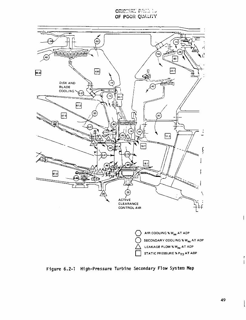
OF POOR QUALITY
DISK AND
BLADE
COOLIN(
[]
ACTIVE
CLEARANCE
CONTROL AIR
I
I
I
\
Figure 6.2-I High-Pressure
O AIR COOLING %Wae AT ADP
O ECONDARY COOLING %WaeAT ADP
LEAKAGE FLOW % Wae AT ADP
F"] STATIC PRESSURE % PT3 AT ADP
Turbine Secondary Flow System Map
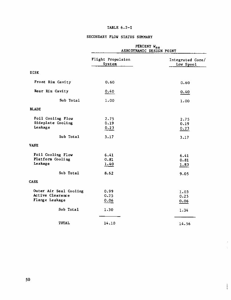
TABLE 6.2-1
SECONDARY FLOW STATUS SUMMARY
PERCENT Wae
A_RODYNAMIC DESIGN POINT
Flight Propulsion
System
Integrated Core/
Low Spool
DISK
Front Rim Cavity
Rear Rim Cavity
Sub Total
0.60
0.40
1.00
0.60
0.40
i. O0
BLADE
Foil Cooling Flow
Sldeplate Cooling
Leakage
Sub Total
2.75
0.19
0.23
3.17
2.75
0.19
0.23
3.17
VANE
Foll Cooling Flow
Platform Cooling
Leakage
Sub Total
6.41
0.81
1.40
8.62
6.41
0.81
1.83
9.05
CASE
Outer Air Seal Cooling
Active Clearance
Flange Leakage
Sub Total
0.99
0.25
0.06
1.30
1.03
0.25
0.06
1.34
TOTAL 14 .i0 14.56
5O

6.3 SECONDARY FLOW SYSTEM DESIGN FEATURES
The main design features in the secondary flow system are shown in Figure
6.3-I. These include a blade coolant supply tangential on-board injection
(TOBI) system, a front rim cavity mini tangential on-board injection (TOBI)
system, boltless rotor sideplates, and a multi knife-edge, stepped high-
pressure compressor discharge seal.
The blade tangential on-board injection system is a high efficiency cascade
design to ensure positive supply of blade cooling air, which is furnished from
the high-pressure compressor inner bleed. Since the system is pressure bal-
anced, inner and outer seals are not necessary. Also, only a small percentage
of air flow (O.l percent of the total engine inlet flow) is required around
the flow guides at the nozzle discharge plane. Furthermore, because the system
is balanced to accomodate the gas path inner diameter pressure, cooling flow
is insensitive to rim seal clearances.
The mini tangential on-board injection system shown in Figure 6.3-2 preswirlsthe front rim cavity and thereby reduces windage heat up that would increase
front side plate temperature. The swirl field also provides a radial pressure
gradient between the blade supply tangential on-board injection system and the
gas path static pressure, thereby effectively linking the blade supply pres-sure to the gas path leading edge inner diameter pressure. This keeps the
ratio of blade supply pressure to gas path inner static pressure fixed and
independent of seal leakage, attachment leakage and blade flow area.
The full ring, boltless sideplate configuration adopted for the Energy
Efficient Engine high-pressure turbine considerably reduces the leakage in-
herent in Conventional segmented sideplates. A diagram of the blade coolant
supply system, showing pressure and flow characteristics, is presented in
Figure 6.3-3. The design blade cooling flow is 2.75 percent of core engine air
flow and is supplied to the blade at an inlet pressure of 53.2 percent of the
total pressure at the high-pressure compressor exit. The tangential on-board
injection dump pressure of 43.1 percent of the total high-pressure compressor
exit pressure is increased to 48.2 percent by the free vortex pressure re-covery, and up to 53.2 precent by solid body rotation in the disk feed
passages. As indicated, the full ring sideplate arrangement is very effective
in reducing leakage. In addition, the use of W-seals at the interface of the
rear plate and blade platfom successfully controls leakage flow.
Other pertinent rotor and turbine case secondary flow features include the
fol lowl ng:
o Rim Seals -- These seals are positioned at the leading and trailing
edge of the blade platfom to isolate the disk cavity from the gas
path. In essence, these serve as flow guides that function like fish-mouth seals to prevent hot gas ingestion and the resulting heat up of
the disk rim.
High-Pressure Compressor Discharge Seal -- The compressor discharge
seal is a nine knife-edge structure with an abradable seal land. This
seal is designed to operate at a very close clearance 0.031 cm
(0.0125 in), permitting minimum leakage flow. The calculated leakage
flow rate is 0.4 percent of the total core engine flow.
51 I

OF POOR QUALITV
J
/ MINI TOBI
BOLTLESS, FULL RINGSIDEPLATE
Figure 6.3-I Secondary Flow System Design Features
52
Figure 6.3-2 Mini Tangential 0n-Board Injection System

598°C (1110°F) J3 43.1
512°C
0.1 (955°F)
/
OF PCOR QUP, LITY
LOW PRESSURE LOSS BLADE COOLANT SUPPLY SYSTEM "
• BOLTLESS TO MINIMIZE PRESSURE DROP AND LEAKAGE
• FULL RING SlDEPLATES WITH W-SEAL TO MINIMIZE
LEAKAGE
" 48.2[
1990 ° F )
0.002
Figure 6.3-3 Flow Characterfstfcs of Blade Coolant Supply System
53

Rear Seal -- A seal at the rear of the high-pressure turbine is usedto provide thrust balance. The net thrust of the high-pressure rotoris presently calculated at 22,241 N (5000 lb) at sea level takeoffcondi ti ons.
Buffer Seal -- This seal, which is located in the proximity of therear seal, is used to separate cool low-pressure compressor dischargeair from high-pressure turbine bore cooling air for the rear bearingcompartment.
Active Clearance Control System -- Turbine case active clearance
control is achieved through an internal system supplied with a mix-
ture of tenth and fifteenth-stage high-pressure compressor bleed
flow, which totals 0.25 percent of the total engine inlet flow. The
impingement of this air cools the full ring rails to control theclearance of the outer air seals. The thermal environment of the
front and rear rails is precisely matched to prevent adverse themalgraidents.
Outer Air Seals -- These seals are ceramic coated and impingementcooled by combustor secondary cooling air. Since the pressure of this
cooling air is relatively high, it is channeled to the intersegmentgap to cool the exposed intermediate seal layer as well as prevent
gas path ingestion.
0 W-Seals and Feather Seals -- Both sealing techniques have proved
effective in minimizing leakage during experimental model_ tests.
These seals are used extensively in the high-pressure turbine design.
6.4 Thermal Analysis
The effectiveness and adequacy of the secondary flow system has been verified
on the basis of results acquired from thermal analyses. Figure 6.4-I shows the
deteiled thermal model element breakup of the rotor and portions of the static
structure required to establish boundary conditions. Figure 6.4.-2 shows an
example of time transient responses for the disk during a snap acceleration/
deceleration. As expected, the rim thermal response is the fastest, while the
bore response is slowest.
Turbine case and outer seal temperatures were generated with the thermal model
shown in Figure 6.4-3. Results of the analysis are presented in Figure 6.4-4,
which shows a time transient response of elements at the ceramic interface in
the front and rear outer air seal rails for a snap acceleration/deceleration.
The ceramic interface temperature is a key parameter for outer air seal
structural Integrity.
54
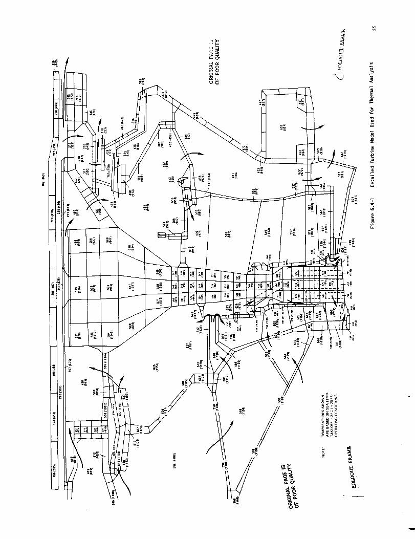

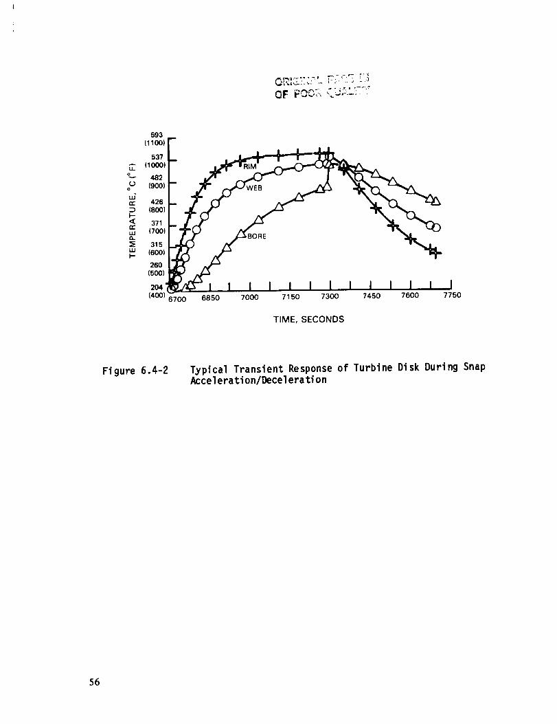
593
(1100) F
°EL 482 -- "
426 ],..,. /I (_ _ _,_ _
,_oo,/ ._.o_ _ "_T_o_371 i,-,,, 1_,-4 r
315 _ _ ' "_,_,_ ,6oo,1.._ /Z-"260 _
(500)204 '
(400) 6700 6850 7000 71 50 7300 7450 7600 7750
TIME, SECONDS
Fi gure 6.4-2 Typical Transient Response of Turbine Disk During SnapAccelerati on/Decel erati on
56

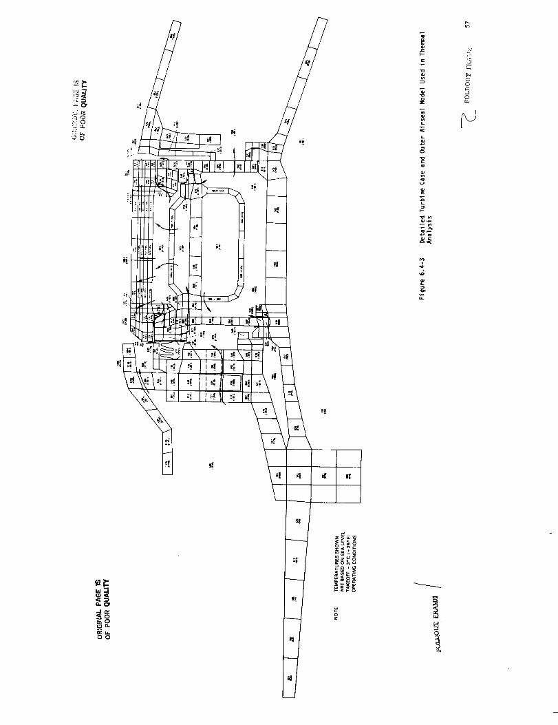
g,
:5
o
o
QO


L.' L__ _1_ :._ __ _,__..._-_._" I, ,I
760
(1400)
704
(1300)
648
(1200)
593LL (1100)
O
rj 537o
- (lOOO)LU
rr 482
I-- (900),<rr 426
Lu (800),,,.,
_; 371iiit- (700)
315
(600)
26O
(500:
204
(400) 6 700
iI I I I l J _L I
1- | l F 1 I i ICERAMIC INTERFACE
REAR RAIL
L'
£
FRONT RAIL
6850 7000 7150 7300 7450 7600
TIME, SECONDS
7750
Figure 6.4-4 Results of Temperature Analysis
58

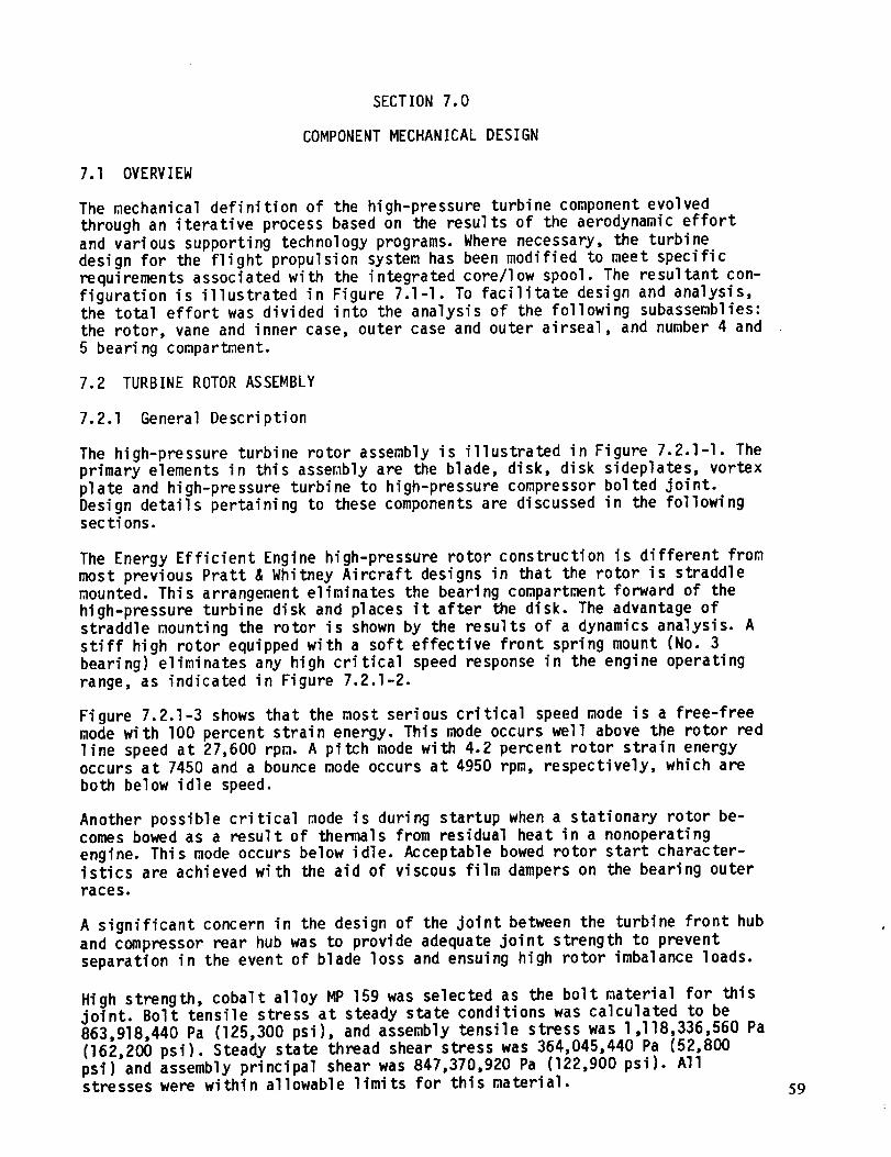
SECTION 7.0
COMPONENT MECHANICAL DESIGN
7.1 OVERVIEW
The mechanical definition of the high-pressure turbine component evolved
through an iterative process based on the results of the aerodynamic effort
and various supporting technology programs. Where necessary, the turbine
design for the flight propulsion system has been modified to meet specific
requirements associated with the integrated core/low spool. The resultant con-
figuration is illustrated in Figure 7.l-l. To facilitate design and analysis,the total effort was divided into the analysis of the following subassemblies:
the rotor, vane and inner case, outer case and outer airseal, and number 4 and
5 bearing compartment.
7.2 TURBINE ROTOR ASSEMBLY
7.2.1 General Description
The high-pressure turbine rotor assembly is illustrated in Figure 7.2.1-I. The
primary elements in this assembly are the blade, disk, disk sideplates, vortex
plate and high-pressure turbine to high-pressure compressor bolted joint.Design details pertaining to these components are discussed in the followingsec tions.
The Energy Efficient Engine high-pressure rotor construction is different from
most previous Pratt & Whitney Aircraft designs in that the rotor is straddlemounted. This arrangement eliminates the bearing compartment forward of the
high-pressure turbine disk and places it after the disk. The advantage of
straddle mounting the rotor is shown by the results of a dynamics analysis. A
stiff high rotor equipped with a soft effective front spring mount (No. 3
bearing) eliminates any high critical speed response in the engine operating
range, as indicated in Figure 7.2.1-2.
Figure 7.2.1-3 shows that the most serious critical speed mode is a free-free
mode with lO0 percent strain energy. This mode occurs well above the rotor red
line speed at 27,600 rpm. A pitch mode with 4.2 percent rotor strain energyoccurs at 7450 and a bounce mode occurs at 4950 rpm, respectively, which are
both below idle speed.
Another possible critical mode is during startup when a stationary rotor be-comes bowed as a result of thermals from residual heat in a nonoperating
engine. This mode occurs below idle. Acceptable bowed rotor start character-istics are achieved with the aid of viscous film dampers on the bearing outer
races.
A significant concern in the design of the joint between the turbine front hub
and compressor rear hub was to provide adequate joint strength to prevent
separation in the event of blade loss and ensuing high rotor imbalance loads.
High strength, cobalt alloy MP 159 was selected as the bolt material for thisjoint. Bolt tensile stress at steady state conditions was calculated to be
863,918,440 Pa (125,300 psi), and assembly tensile stress was I,I18,336,560 Pa
(162,200 psi). Steady state thread shear stress was 364,045,440 Pa (52,800
psi) and assembly principal shear was 847,370,920 Pa (122,900 psi). Allstresses were within allowable limits for this material. 59

OR|G_N_LP_G" |_
OF POOR QUALITY
I_ 53.0 CM (20.9 IN)
12.9
(5.1 IN) R
_1--!
DISCHARGE
SEAL
NO. 4-5 BEARING
COMPARTMENT
BLADENOTE:
VANE INNER 40.6 CM
(16.0 IN) R
VA_
48.0 CM OUTER CASE AND
(18.9 IN) R OUTER AIR SEAL
1
DIMENSIONS ARE NOMINAL,
RADII ARE MEASURED FROMENGINE CENTER LINE
Figure 7.l-I High-Pressure Turbine Mechanical Configuration
.9 IN) R39.3 CM (15.5 IN) _I
I11.9 CM _['_"-'_1_--_
12.9 CM (5.1 IN) R (4.7 IN)12.9 CM (5.1 IN) R
HIGH PRESSURE TURBINE
TO HIGH PRESSURE COMPRESSOR
BOLTED JOINT
22.3 CM (8.8 IN)
NOTE:
(8.0 IN) R
DIMENSIONS ARE NOMINAL.
RADII ARE MEASURED FROMENGINE CENTER LINE
VORTEX PLATE SK
SIDEPLATES
40.6 CM (16.0 IN) R
f
60
Figure 7.2.1-I High-Pressure Turbine Rotor Assembly
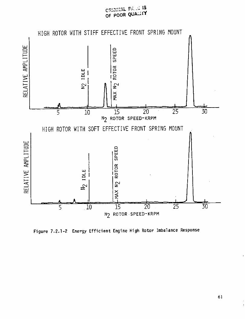
OF POOR QUAL_I'Y
HIGHROTORI_ITHSTIFFEFFECTIVEFRONTSPRINGMOUNT
L_
._Jr_
._J
WQ_Q_
i,, 0
5 10 15 2"0 25 30
N2 ROTOR SPEED-KRPM
HIGHROTORWITHSOFTEFFECTIVEFRONTSPRINGMOUNT
l_u
c_
uJ
uJuJ0_
n-O
0n-
Z
X
5 i0 15 2O 25
N2 ROTOR ,SPEED-KRPM
3O
Figure 7.2.1-2 Energy Efficient Engine High Rotor Imbalance Response
61
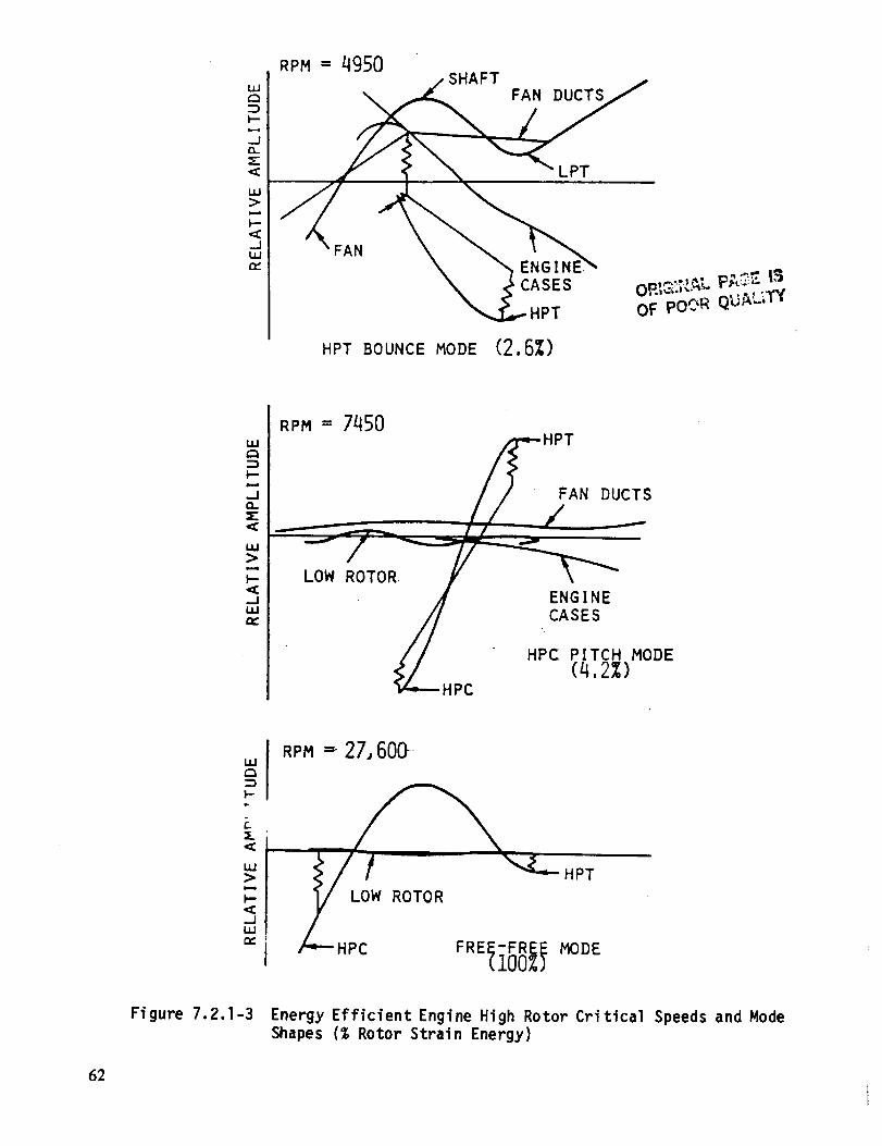
RPM= 4950
_ SHAFT I
_ CASES w-, ......HPT OF poOR QUAL_"I'Y
HPT BOUNCE MODE (2,6_)
ILl
I'--
--I
LU
I'--
..IILln,."
RPM- 7450
HPTFAN DUCTS
/ -
LOW ROTO
. G
_HPC HPC PITCH MODE(4,2%)
LMC3
F-
L:s
uJ>
l=-
..JLIJn.*
RPM =" 27, 600
ROTOR
Figure 7.2.1-3 Energy Efficient Engine High Rotor Critical Speeds and Mode
Shapes (% Rotor Strain Energy)
62
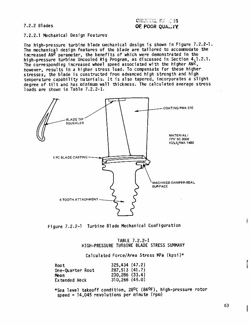
7.2.2 Blades OF. POOR QUAL;IY
7.2.2.1 Mechanical Design Features
The high-pressure turbine blade mechanical design is shown in Figure 7.2.2-I.The mechanical design features of the blade are tailored to accommodate the
increased AN2 parameter, the benefits of which were demonstrated in the
high-pressure turbine Uncooled Rig Program, as discussed in Section 4.1.2.1.
The corresponding increased wheel speed associated with the higher AN2,
however, results in a higher stress load. To compensate for these higher
stresses, the blade is constructed from advanced high strength and high
temperature capability materials. It is also tapered, incorporates a slight
degree of tilt and has minimum wall thickness. The calculated average stressloads are shown in Table 7.2.2-I.
SQUEALER
_COATING PWA 270
MATERIAL:
FPS' SC 2000
IC/LS)PWA 1480
1 PC BLADE CASTING
HINED DAMPER-SEAL
SURFACE
5 TOOTH ATTACHMENT
Figure 7.2.2-I Turbine Blade Mechanical Configuration
TABLE 7.2.2-I
HIGH-PRESSURE TURBINE BLADE STRESS SUMMARY
Calculated Force/Area Stress MPa (kpsi)*
Root
One-Quarter RootMeanExtended Neck
325,434 (47.2)
287,513 (41.7)
230,286 (33.4)
310,266 (45.0)
*Sea level takeoff condition, 28°C (84°F), high-pressure rotor
speed = 14,045 revolutions per minute (rpm)
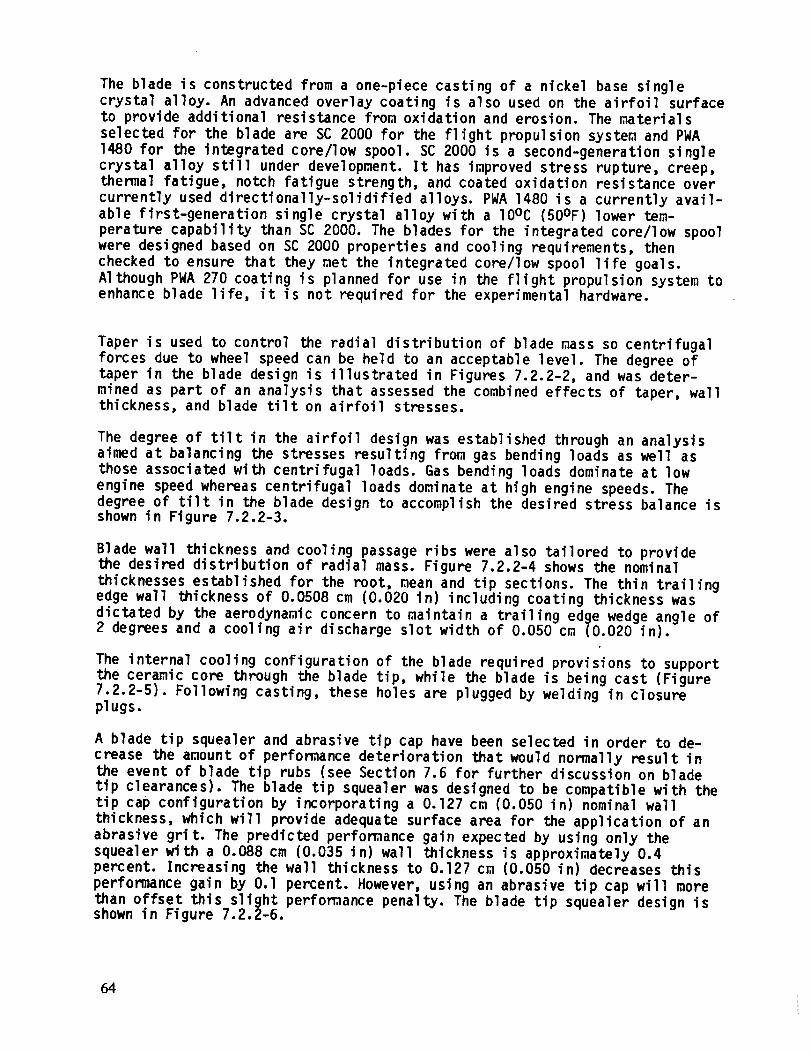
The blade is constructed from a one-piece casting of a nickel base singlecrystal alloy. An advanced overlay coating is also used on the airfoil surfaceto provide additional resistance from oxidation and erosion. The materialsselected for the blade are SC 2000 for the flight propulsion system and PWA1480 for the integrated core/low spool. SC 2000 is a second-generation stnglecrystal alloy still under development. It has improved stress rupture, creep,thermal fatigue, notch fatigue strength, and coated oxidation resistance overcurrently used directionally-solidified alloys. PWA 1480 is a currently avail-able first-generation single crystal alloy with a 10oc (50OF) lower tem-perature capability than SC 2000. The blades for the integrated core/low spoolwere designed based on SC 2000 properties and cooling requirements, thenchecked to ensure that they met the integrated core/low spool life goals.Although PWA 270 coating is planned for use in the flight propulsion system toenhance blade life, it is not required for the experimental hardware.
Taper is used to control the radial distribution of blade mass so centrifugal
forces due to wheel speed can be held to an acceptable level. The degree oftaper in the blade design is illustrated in Figures 7.2.2-2, and was deter-
mined as part of an analysis that assessed the combined effects of taper, wallthickness, and blade tilt on airfoil stresses.
The degree of tilt in the airfoil design was established through an analysisaimed at balancing the stresses resulting from gas bending loads as well as
those associated with centrifugal loads. Gas bending loads dominate at low
engine speed whereas centrifugal loads dominate at high engine speeds. Thedegree of tilt in the blade design to accomplish the desired stress balance isshown in Figure 7.2.2-3.
Blade wall thickness and cooling passage ribs were also tailored to providethe desired distribution of radial mass. Figure 7.2.2-4 shows the nominal
thicknesses established for the root, mean and tip sections. The thin trailingedge wall thickness of 0.0508 cm (0.020 in) including coating thickness was
dictated by the aerodynamic concern to maintain a trailing edge wedge angle of2 degrees and a cooling air discharge slot width of 0.050 cm (0.020 in).
The internal cooling configuration of the blade required provisions to supportthe ceramic core through the blade tip, while the blade is being cast (Figure7.2.2-5). Following casting, these holes are plugged by welding in closureplugs.
A blade tip squealer and abrasive tip cap have been selected in order to de-
crease the amount of performance deterioration that would normally result in
the event of blade tip rubs (see Section 7.6 for further discussion on blade
tip clearances). The blade tip squealer was designed to be compatible with thetip cap configuration by incorporating a 0.127 cm (0.050 in) nominal wall
thickness, which will provide adequate surface area for the application of an
abrasive grit. The predicted performance gain expected by using only the
squealer with a 0.088 cm (0.035 in) wall thickness is approximately 0.4percent. Increasing the wall thickness to 0.127 cm (0.050 in) decreases this
performance gain by O.l percent. However, using an abrasive tip cap will more
than offset this slight performance penalty. The blade tip squealer design isshown in Figure 7.2.2-6.
64

--LT
- LR_
AXIAL
Figure 7.2.2-2 Radial Taper in Turbine Blade To Minimize Stress
I U
U
TRUE
RADIAL
I-TIP
\ i
STACKING _ [
LINE _i \ - 314 TIP
- MEANI
- 1/4 ROOT
- ROOT
TIP
3/4 TIP
MEAN
1/4 ROOT
)OT
Figure 7.2.2-3 Degree of Tilt in the High-Pressure Turbine Blade To Achievethe Desired Balance Between Gas Bending Load Stresses and
Stresses Resulting from Centrifugal Loads 65
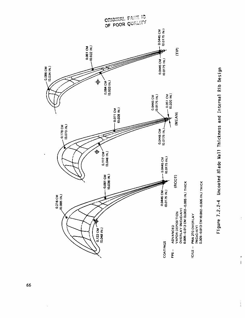
OF pOOR _ U'-r>-L:'i''y
Z
e.-
,p
a--L
4_t--
t--
e-
,p.e-
k--
0_J_.-.._
IOJ
(D
ofmb-
66

0_"'_'_ FACE _S
OF POOR QUALITY
CORE SUPPORT ACCESS HOLES
%
Figure 7.2.2-5 Core Support Method
Figure 7.2.2-6 Blade Tip Squealer Geometry
67
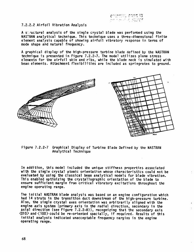
7.2.2.2 Airfoil Vibration Analysis
A s;;_uctural analysis of the single crystal blade was perfomed using the
NASTRAN analytical technique. This technique uses a three-dimensional finite
element analysis capable of showing airfoil vibratory response in terms of
mode shape and natural frequency.
A graphical display of the high-pressure turbine blade defined by the NASTRAN
technique is presented in Figure 7.2.2-7. The model utilizes plane stress
ele_nts for the airfoil skin and ribs, while the blade neck is simulated with
beam elements. Attachment flexibilities are included as springrates to ground.
L_
Figure 7.2.2-7 Graphical Display of Turbine Blade Defined by the NASTRAN
Analytical Technique
In addition, this model included the unique stiffness properties associated
with the single crystal atomic orientation whose characteristics could not be
evaluated by using the classical beam analytical models for blade vibration.
This enabled optimizing the crystallographic orientation of the blade to
ensure sufficient margin from critical vibratory excitations throughout theengine operating range.
The initial NASTRAN blade analysis was based on an engine configuration which
had 14 struts in the transition duct downstream of the high-pressure turbine.
Also, the single crystal axes orientation was arbitrarily aligned with the
engine axis system (primary axis in the radial direction, secondary in the
axial direction (see Figure 7.2.2-8)), recognizing that the secondary axis
_OlO> and {I00} could be re-oriented spacially, if required. Results of this
initial analysis indicated unacceptable frequency margins in the engineoperating range.
68
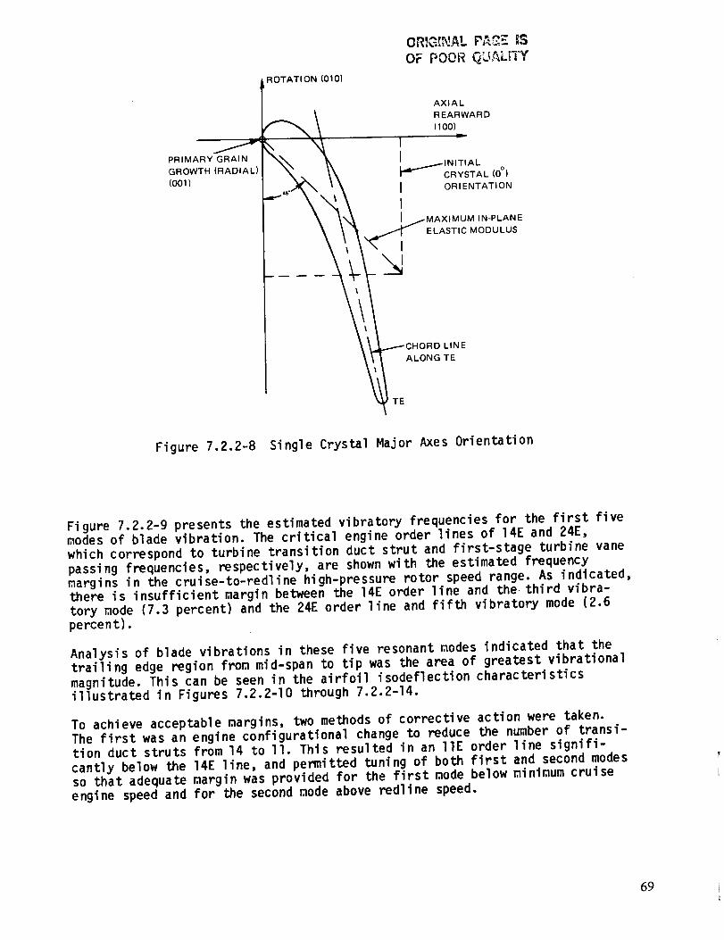
PRIMARY GRAIN
GROWTH (RADIAL)
(001)
ROTATI ON (010)
OR,_G{NAL P_ _S¢.,/ _. ,,,OF POOR _LI,_Lt1_
AXIAL
REARWARD
( 100}
I =I
CRYSTAL (0 °)
I ORIENTATION
IMAXlMUM IN-PLANE
ELASTIC MODULUS
N
rRD LINE
ALONG TE
TE
Figure 7.2.2-8 Single Crystal Major Axes Orientation
Figure 7.2.2-9 presents the estimated vibratory frequencies for the first five
modes of blade vibration. The critical engine order lines of 14E and 24E,
which correspond to turbine transition duct strut and first-stage turbine vane
passing frequencies, respectively, are shown with the estimated frequency
margins in the cruise-to-redline high-pressure rotor speed range. As indicated,there is insufficient margin between the 14E order line and the third vibra-
tory mode (7.3 percent) and the 24E order line and fifth vibratory mode (2.6percent).
Analysis of blade vibrations in these five resonant modes indicated that the
trailing edge region from mid-span to tip was the area of greatest vibrational
magnitude. This can be seen in the airfoil isodeflection characteristics
illustrated in Figures 7.2.2-I0 through 7.2.2-14.
To achieve acceptable margins, two methods of corrective action were taken.
The first was an engine configurational change to reduce the number of transi-tion duct struts from 14 to II. This resulted in an lie order line signifi-
cantly below the 14E line, and permitted tuning of both first and second modesso that adequate margin was provided for the first mode below minimum cruise
engine speed and for the second mode above redline speed.
69
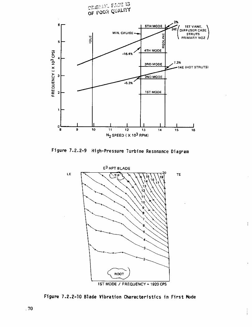
A
(./3
r.J03O
Xv
>.
ZuJ
ClIJJn.*u..
6
5_
4--
3 --
2--
1 --
08
J
MIN. CRUISE _
5TH MODE
4TH MODE
3RD MODE
I
1ST MODE
2%
.t._:-_ lSTVANE.\v 2,,E/D,F_USERCASE_
t STRUTS /'t PRIMARY NOZ I
_7.3%
,_..,.,," 14E (HOT STRUTS)
I I I I I I I I9 10 11 12 13 14 15 16
N 2 SPEED ( X 103 RPM)
Figure 7.2.2-9 High-Pressure Turbine Resonance Diagram
LE
E3 HPT BLADE
1ST MODE / FREQUENCY = 1920 CPS
TE
Figure 7.2.2-10 Blade Vibration Characteristics in First Mode
•70

Fi gure
LE
7.2.2-II
E 3 HPT BLADE
I I I
\2 \
2ND MODE / FREQUENCY = 2825 CPS
Y
TE
,17
.15
.13
,11
Blade Vibration Characteristics in Second Mode
E 3 HPT BLADE
,16
\ ,C >84\_ 7
3RD M_UENCY = 3560C_PS
Figure 7.2.2-12 Blade Vibration Characteristics in Third Mode
?!
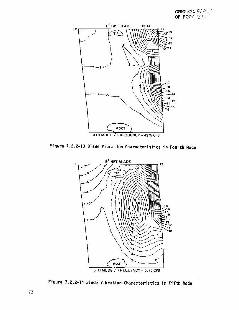
LEE3 HPT BLADE 12 13
TE
ORIG!I','_.L F_,-:< '
4TH MODE / FREQUENCY = 4375 CPS
Figure 7.2.2-13 Blade Vibration Characteristics in Fourth Mode
E3 HPT BLADELE TE
5TH MODE / FREQUENCY = 5675 CPS
Figure 7.2.2-14 Blade Vibration Characteristics in Fifth Mode
72
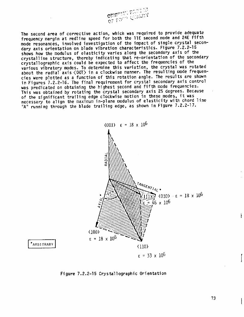
The second area of corrective action, which was required to provide adequate
frequency margin at redline speed for both the liE second mode and 24E fifth
mode resonances, involved investigation of the impact of single crystal secon-
dary axis orientation on blade vibration characteristics. Figure 7.2.2-15
shows how the _odulus of elasticity varies along the secondary axis of the
crystalline structure, thereby indicating that re-orientation of the secondarycrystallographic axis could be expected to affect the frequencies of the
various vibratory modes. To determine this variation, the crystal was rotated
about the radial axis {001} in a clockwise manner. The resulting mode frequen-
cies were plotted as a function of this rotation angle. The results are shown
in Figures 7.2.2-16. The final requirement for crystal secondary axis control
was predicated on obtaining the highest second and fifth mode frequencies.
This was obtained by rotating the crystal secondary axis 25 degrees. Because
of the significant trailing edge clockwise motion in these modes, it was
necessary to align the maximum in-plane modulus of elasticity with chord line
"A" running through the blade trailing edge, as shown in Figure 7.2.2-17.
(001) E = 18 x 106
J'ARBITRARY I
<i00)
E = 18 x 106
(ii0)
E = 33 x 106
Figure 7.2.2-15 Crystallographic Orientation
73 I

1.08 MODE
OF PCOR QUALI'I_f
MODE
uJu3
,m
1.(>
1.02
1.00
0.98
2ND
3RD MODE
1ST MODE
0.96
0.940 10
I I I I20 30 40 50 60 70 80 90
ROTATION ANGLE ABOUT 001 AXIS , DEGREES
Figure 7.2.2-16 Predicted Frequencies Versus Crystal SecondaryAngle
I100
Orientation
ROTATION (010)
PRIMARY GRAIN "_. 25 ° _
GROWTH RADIAL (001) "_ ,_'
AXIAL
REARWARD (100)
REQUIRED ROTATION FROM
INITIAL ORIENTATION
/ /
/ /
MAXIMUM IN-PLANE_" / ELASTIC MODULUS
\ /._ /
',,. /,%
T°E.
LINE "A"
CHORD LINE ALONG
TRAILING EDGE
Figure 7.2.2-17 Axial Shift in Crystal Orientation
74

An analysis of this r,lodifiedconfiguration demonstrated acceptable frequencymargins for both liE and 24E engine order lines. The results are presented in
the resonance diagram in Figure 7.2.2-18.
Blade platfom frequencies were calculated to ensure that no vane passing
resonances would occur in the engine operating range. Both lie and 24E reso-
nances were predicted to be well above redline speed.
The reduced velocity flutter parameter for the high-pressure turbine blades is
2.1, which is well below the established design limit for shroudless turbine
blades. The long chord and high frequency characteristics of the blade contri-
bute to this stability. Blade damper load was set at 4448 N (1000 Ib) to pro-vide effective control of both buffet stress and resonant stress. The buffet
stress analysis assumed that the combustor liner pressure drop was 2.5 percent
of total pressure at the high-pressure compressor exit location.
Axial gapping between the blade, first vane, and hot strut was also analyzed.
The spacing along a streamline at the outer diameter between the blade trail-
ing edge and the hot strut leading edge was established at three times the
maximum thickness of the strut. The axial meanline gap between the blade lead-
ing edge and the first vane trailing edge was established at approximately0.33 times the vane meanline axial chord.
x
z
=o_rU_
7
3
2_
/
o I
25 _ CRYSTAL ANGLE
11 HOT STRUTS
=_==
i 5TH MODE I / 10.7%
r- _24 E
JI"7 ISTVANE \/(_u i Of FFUSER CASE I
/ I z _ STRUTS f
/ I P3 \PRIMARY NOZ./
4TH MODE
3RD MODE
2NO MODE
1ST MODE
12.2%
1 tE (HOT STRUTS)
I 1I I I [9 10 11 12 13 14 15 16
N2 SPEED (× lO'RPM)
Figure 7.2.2-18 Predicted Frequency with Modified Configuration
?5
7.2.3 Blade Attachment
7.2.3.1 Mechanical Design Features
The attachment for the high-pressure turbine blade is a five-tooth firtree
design that evolved from a four-tooth design during the preliminary designeffort for the high-pressure turbine component. Primary contributing factors
to this change consisted of: (1) a flowpath revision that increased the plat-
form pull by 20 percent, and (2) a blade neck extension of 0.584 cm (0.23 in),
which increased neck pull by 50 percent. With the original four-tooth config-
uration, the combination of these factors increased the concentrated stress in
the attachment above the allowable level. Consequently, the five-tooth geo-
metry was adopted.
7.2.3.2 Structural Analysis
A stress analysis of the blade attachment geometry was conducted by using a
finite element technique. Results are su_m_arized in Table 7.2.3-I for the
nominal stresses of shear, bending, bearing, and tension. These results are
based on the most stress-limiting tooth in the firtree geometry.
As indicated by these results, the predicted shear and bearing stresses exceed
the maximum allowable limit by 8 and II percent, respectively. The remaining
values are substantially below limit, with the exception of tension, which is
only marginally higher than the acceptable limit. However, rig testing of
single crystal root attachment specimens has been successfully conducted bothat and above these stress levels with no evidence of material distress. On the
basis of these experimental data, the blade attachment configuration is
structurally adequate and the predictions are somewhat conservative.
Additional stress analyses were perfomed using two-dimensional finite element
technology to ensure concentrated attachment stresses provided adequate life
in the integrated core/low spool and the flight propulsion system. Life goals
are lO00 and 12,000 cycles, respectively, assuming the appropriate materials.The results of this analysis are presented in Figure 7.2.3-I. Estimates for
the integrated core/low spool show that all stresses are below the maximum
level, thereby attaining the lO00 cycle goal. However, for the higher cyclic
life requirements of the flight propulsion system, blade stresses are lowerthan the allowable limit but stresses are also higher on the disk by approxi-
mately the same percentage. This result suggests that the disk broach geometrycan be optimized to achieve the desired stress balance between the blade and
disk to meet the 12,000 cycle life goal.
76
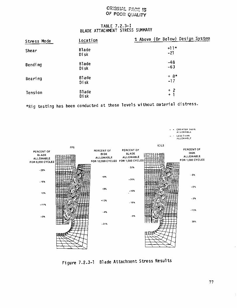
Stress Mode
Shear
Bending
Beam ng
Tension
*Rig testing has been
BLADE
Location
Blade
Disk
BladeDisk
Blade
Disk
BladeDisk
conducted
OF PO0_-,_QUALITY
TABLE 7.2.3-IATTACHMENT STRESS SUMMARY
% Above (Or Below)
-48-63
+2+l
at these levels without material
Design System
di stress.
FPS
PERCENT OF
BLADE_IIT][
ALLOWARLE !lit I_ .....
,OR .OOOCYCLES-28%
-16%
-10%
--11%
-9%
PERCENT OF PERCENT OF
DISK BLADE
ALLOWABLE ALLOWABLE
FOR 12.000CYCLES FOR 1,000 CYCLES
-32%
+B%
-20%
*B%-15%
+_2%
-16%
-4%
-9%
-31%
IC/LS
* = GREATER THAN
ALLOWABLE
= LESSTHAN
ALLOWABLE
PERCENT OF
DISK
ALLOWABLE
FOR 1,000 CYCLES
--5%
-5%
-2%
-15%
-39%
Figure 7.2.3-I Blade Attachment Stress Results
7?
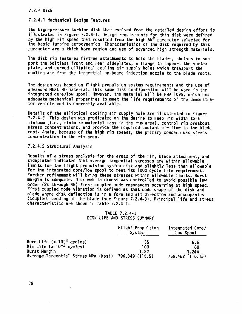
7.2.4 Disk
7.2.4.1 Mechanical Design Features
The high-pressure turbine disk that evolved from the detailed design effort is
illustrated in Figure 7.2.4-I. Design requirements for this disk were defined
by the high rim speed that resulted from the high AN 2 parameter selected for
the basic turbine aerodynamics. Characteristics of the disk required by this
parameter are a thick bore region and use of advanced high strength materials.
The disk rim features firtree attachments to hold the blades, shelves to sup-
port the boltless front and rear sideplates, a flange to support the vortex
plate, and curved elliptical cooling air supply holes which transport the
cooling air from the tangential on-board injection nozzle to the blade roots.
The design was based on flight propulsion system requirements and the use ofadvanced MERL 80 material. This same disk configuration will be used in theintegrated core/low spool. However, the material will be PWA I099, which has
adequate mechanical properties to meet the life requirements of the demonstra-tor vehicle and is currently available.
Details of the elliptical cooling air supply hole are illustrated in Figure7.2.4-2. This design was predicated on the desire to keep rim width to a
minimum (i.e., minimize material mass in the rim area), control rim breakout
stress concentrations, and provide the required coolant air flow to the blade
root. Again, because of the high rim speeds, the primary concern was stressconcentration in the rim area.
7.2.4.2 Structural Analysis
Results of a stress analysis for the areas of the rim, blade attachment, andsideplates indicated that average tangential stresses are within allowable
limits for the flight propulsion system disk and slightly less than allowable
for the integrated core/low spool to meet its lOO0 cycle life requirement.
Further refinement will bring these stresses within a11owable limits. Burst
margin is adequate. Disk web thickness was controlled to avoid possible low
order (2E through 4E) first coupled mode resonances occurring at high speed.First coupled mode vibration is defined as that mode shape of the disk and
blade where disk deflection is in a fore and aft direction and accompanies
(coupled) bending of the blade (see Figure 7.2.4-3). Principal life and stresscharacteristics are shown in Table 7.2.4-I.
TABLE 7.2.4-I
DISK LIFE AND STRESS SUMMARY
Bore Life (x 107,3 cycles)
Rim Life (x I0-° cycles)
Burst Margin
Average Tangential Stress MPa (kpsi)
Flight Propulsion
• _stemIntegrated Core/
Low Spool
35 8.5
I00 80
l.22 l.244
796,349 (I15.5) 759,462 (llO.15)
78
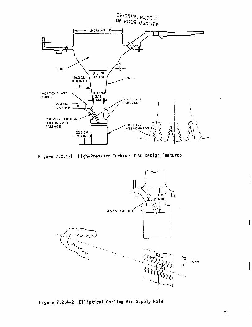
OF POOR QU_LITy
1_-11.9 CM(4.7,N)----_._
(I.6 IN}
20.3 CM 4,0 CM WEB(8.0 IN) R
VORTEX
SHELF
25.4(10.0 IN) R
CURVED,COOLING AIR
PASSAGE
32.5 CM
(12.8 IN)
ATE
/ 1' !
Figure 7.2.4-I High-Pressure Turbine Disk Design Features
Figure 7.2.4-2 Elliptical Cooling Air Supply Hole
?9
1ST COUPLED VIBRATION MODE
#
. i S
'\ (_)k
1b
I !I #
_.4 L---
1_2
ORIGINAL PA_ -c- [SOF POOR QUAL!TY
2 NODAL DIAMETERS
"_ +
i
,/
w
+ = MOTION TOWARD OBSERVER
- MOTION AWAY FROM OBSERVER
Figure 7.2.4-3 Schematic Showing Disk and Blade Deflections Caused by FirstCoupled Mode Vibration
Low cycle fatigue (LCF) requirements for the disk, sideplates and vortex plate
were set at 12,DO0 cycles. In order to assess disk low cycle fatigue character-
istics, a finite element analysis was undertaken. Figure 7.2.4-4 shows the
finite element break-up used, along with the boundary conditions assumed for
the analysis. To account for stresses generated along the curved elliptical
cooling air passage, a three-dimensional boundary integral equation analytical
model was used. The combined results of these analyses are summarized inFigure 7.2.4-5, which shows the low cycle fatigue lives for the critical areas
of the turbine rim. As shown, calculated lives in three critical areas exceed
requirements. Since the low cycle fatigue properties of notched MERL 80 and
PWA I099 materials are identical, the same life is predicted for both the
flight propulsion system and the integrated core/low spool.
7.2.5 Sideplates and Vortex Plate
7.2.5.1 Mechanical Design Features
The disk sideplates and vortex plate are illustrated in Figure 7.2.5-I. Thefull ring sideplates perform a dual function -- blade retention and sealing in
the rim areas. Axial loads at the critical sealing areas are generated by
centrifugal loads, acting on the sideplates that are canted away from the diskrim. Undesireable retention holes in the sideplates were eliminated by design-
ing the sideplates to be trapped by bayonet connectors (engaged lugs and
slots) instead of conventional bolting arrangements. Stress analysis showed
that conventional bolting designs resulted in unacceptably high bolt and bolt
hole stresses. Leakage is controlled by damper seals sealing axially along the
blade platform and by a W-seal trapped by the blade and rear sideplate. Typical
sideplate loads are shown in Figure 7.2.5-2.
80

ORIGIHAL P_SGE |_OF POOR QUALITY
AXIAL
PRESSURE
=333,501 Pa
(48.37 PSI)
PRESSURE_ = 206,844 Pa-" (30 PSI)
(29,862 Ibs
AXIAL
PRESSURE
=1,176,873 Pa
(170.69 PSI)
I 6RADIAL
= 0.1424 CM (0.0561 IN)
6AXIA L= 0.0 cm (0.0 in)
SPEED = 13,921 RPM
Figure 7.2.4-4 Boundary Conditions Used in Disk Structural Analysis
81

OF pOOR QU_L_
25,000
FRONT
S I D EP LA T E ._.._._..._ _,_,
60,000
20,000
30 0OO > 1OO,0OO DISK
VORTEX
PLATE
NOTE: IC/LS LIVES ALL
> 1000 CYCLES
REAR SiDEPLATE
1)_ 40,000
25,000
\ 40,000 CYCLES
Figure 7.2.4-5 Flight Propulsion System Disk and Sideplate Calculated Minimm,1Low Cycle Fatigue Life Levels
VORTEX
PLATE
BAYONET SNAP
DIA. RETENTION _-_._
\\L
RIM CAVITY SEALING
PRESSURE LOAD /I
SIDEPLATES
DISK
FEATURES
OUTER DIAMETER
CONTACT LOAD
W/SEAL
BLADE
82 Figure 7.2.5-1 Disk Sideplate and Vortex Plate Design
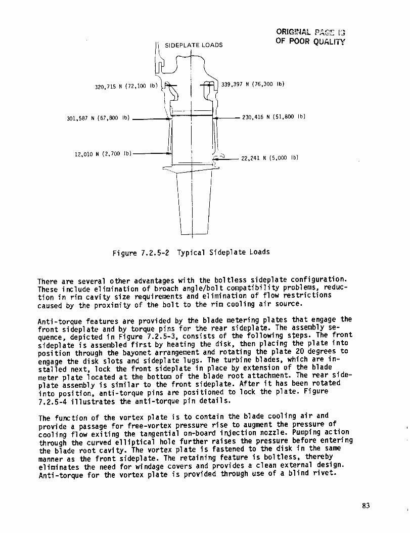
/SIDEPLATE
320,715 N (72,100 Ib)_
301,587 N (67,800 Ib)
LOADS
ORIG!NAL _"'_ [3
OF POOR QUALI,_y
339,397 N (76,300 Ib)
_230,416 N (51,8OO Ib)
12,O10 N (2,700 Ib)22,241 N (5,000 Ib)
Figure 7.2.5-2 Typical Sideplate Loads
There are several other advantages with the boltless sideplate configuration.
These include elimination of broach angle/bolt compatibility problems, reduc-
tion in rim cavity size requirements and elimination of flow restrictions
caused by the proximity of the bolt to the rim cooling air source.
Anti-torque features are provided by the blade metering plates that engage thefront sideplate and by torque pins for the rear sideplate. The assembly se-
quence, depicted in Figure 7.2.5-3, consists of the following sSeps. The front
sideplate is assembled first by heating the disk, then placing the plate into
position through the bayonet arrangement and rotating the plate 20 degrees to
engage the disk slots and sideplate lugs. The turbine blades, which are in-stalled next, lock the front sideplate in place by extension of the blade
meter plate located at the bottom of the blade root attachment. The rear side-
plate assembly is similar to the front sideplate. After it has been rotated
into position, anti-torque pins are positioned to lock the plate. Figure
7.2.5-4 illustrates the anti-torque pin details.
The function of the vortex plate is to contain the blade cooling air and
provide a passage for free-vortex pressure rise to augment the pressure of
cooling flow exiting the tangential on-board injection nozzle. Pumping action
through the curved elliptical hole further raises the pressure before enteringthe blade root cavity. The vortex plate is fastened to the disk in the same
manner as the front sideplate. The retaining feature is boltless, thereby
eliminates the need for windage covers and provides a clean external design.
Anti-torque for the vortex plate is provided through use of a blind rivet.
83
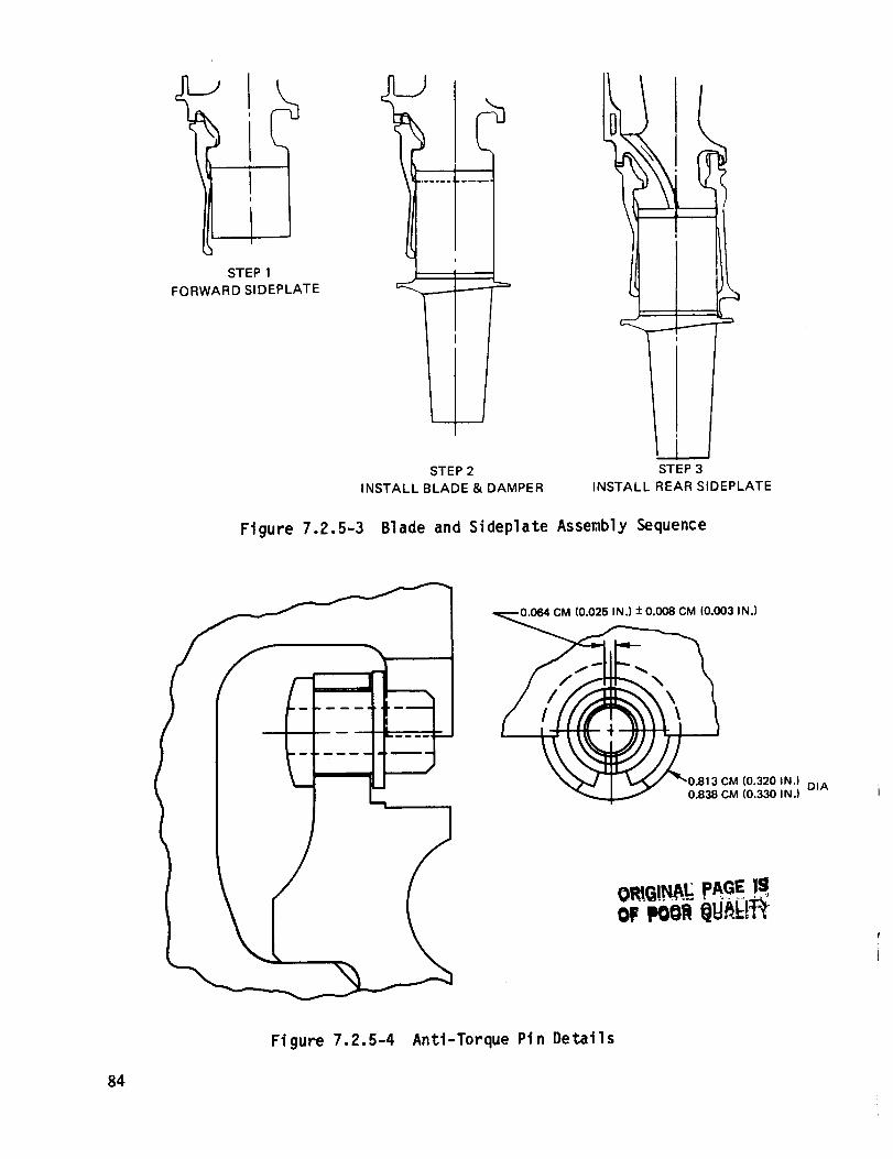
STEP 1
FORWARD SIDEPLATE
i
!
IJ
I
STEP 2
INSTALL BLADE & DAMPER
Figure 7.2.5-3 Blade and Sideplate
STEP 3
INSTALL REAR SIDEPLATE
Assembly Sequence
• CM (0.025 IN.) + 0.008 CM (0.003 IN.)
0.813CM (0.320 IN.) DIA0.838 CM (0.330 IN.)
oeeoOi QY gl
Figure 7.2.5-4 Anti-Torque Pin Details
84
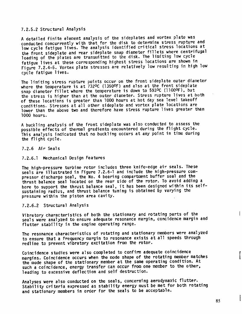
7.2.5.2 Structural Analysis
A detailed finite element analysis of the sideplates and vortex plate was
conducted concurrently with that for the disk to determine stress rupture and
low cycle fatigue lives. The analysis identified critical stress locations at
the front sideplate and rear sideplate snap diameter fillets where centrifugalloading of the plates are transraitted to the disk. The limiting low cycle
fatigue lives at these corresponding highest stress locations are shown in
Figure 7.2.4-5. Vortex plate stresses are relatively low resulting in high low
cycle fatigue lives.
The limiting stress rupture points occur on the front sideplate outer diameter
where the temperature is at 732oc (1350OF) and also at the front sideplatesnap diameter fillet where the temperature is down to 593oc (llO0OF), but
the stress is higher than at the outer diameter. Stress rupture lives at both
of these locations is greater than 1000 hours at hot day sea level takeoff
conditions. Stresses at all other sideplate and vortex plate locations are
lower than the above two and therefore have stress rupture lives greater thanlO00 hours.
A buckling analysis of the front sideplate was also conducted to assess the
possible effects of thermal gradients encountered during the flight cycle.
This analysis indicated that no buckling occurs at any point in time duringthe flight cycle.
7.2.6 Air Seals
7.2.6.1 Mechanical Design Features
The high-pressure turbine rotor includes three knife-edge air seals. These
seals are illustrated in Figure 7.2.6-I and include the high-pressure com-
pressor discharge seal, the No. 4 bearing compartment buffer seal and thethrust balance seal located on the rear side of the rotor. To avoid adding a
bore to support the thrust balance seal, it has been designed within its self-
sustaining radius, and thrust balance tuning is obtained by varying thepressure within the piston area cavity.
7.2.6.2 Structural Analysis
Vibratory characteristics of both the stationary and rotating parts of the
seals were analyzed to ensure adequate resonance margin, concidence margin and
flutter stability in the engine operating range.
The resonance characteristics of rotating and stationary members were analyzed
to ensure that a frequency margin to resonance exists at all speeds through
redline to prevent vibratory excitation from the rotor.
Coincidence studies were also completed to confirm adequate coincidence
margins. Coincidence occurs when the mode shape of the rotating member matches
the mode shape of the stationary member at the same operating condition. At
such a coincidence, energy transfer can occur from one member to the other,
leading to excessive deflection and self destruction.
Analyses were also conducted on the seals, concerning aerodynamic flutter.
Stability criteria expressed as stability energy must be met for both rotating
and stationary members in order for the seals to be acceptable.
85
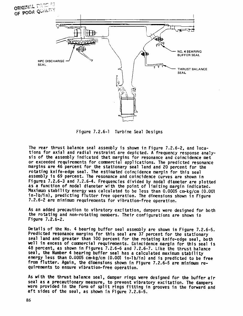
OF pOOP. Q _i_L__'_
NO. 4 BEARINGBUFFER SEAL
HPC DISCHARGE
SEAL
THRUST BALANCE
SEAL
Figure 7.2.6-I Turbine Seal Designs
The rear thrust balance seal assembly is shown in Figure 7.2.6-2, and loca-
tions for axial and radial restraint are depicted. A frequency response analy-sis of the assembly indicated that margins for resonance and coincidence met
or exceeded requirements for commercial applications. The predicted resonancemargins are 46 percent for the stationary seal land and 20 percent for the
rotating knife-edge seal. The estimated coincidence margin for this sealassembly is 69 percent. The resonance and coincidence curves are shown in
Figures 7.2.6-3 and 7.2.6-4. Frequencies divided by nodal diameter are plotted
as a function of nodal diameter with the point of limiting margin indicated.
Maximum stability energy was calculated to be less than 0.0005 cm-kg/cm (O.OOl
in-lb/in), predicting flutter free operation. The dimensions shown in Figure7.2.6-2 are minimum requirements for vibration-free operation.
As an added precaution to vibratory excitation, dampers were designed for both
the rotating and non-rotating members. Their configurations are shown inFigure 7.2.6-2.
Details of the No. 4 bearing buffer seal assembly are shown in Figure 7.2.6-5.
Predicted resonance margins for this seal are 37 percent for the stationary
seal land and greater than lO0 percent for the rotating knife-edge seal, bothwell in excess of commercial requirements. Coincidence margin for this seal is
48 percent, as shown in Figures 7.2.6-6 and 7.2.6-7. Like the thrust balance
seal, the Number 4 bearing buffer seal has a calculated maximum stability
energy less than 0.0005 cm-kg/cm (O.OOl in-lb/in) and is predicted to be free
from flutter. Again, the dimensions shown in Figure 7.2.6-5 are minimum re-
quirements to ensure vibration-free operation.
As with the thrust balance seal, damper rings were designed for the buffer air
seal as a precautionary measure, to prevent vibratory excitation. The damperswere provided in the form of split rings fitting in grooves in the forward and
aft sides of the seal, as shown in Figure 7.2.6-5.
86
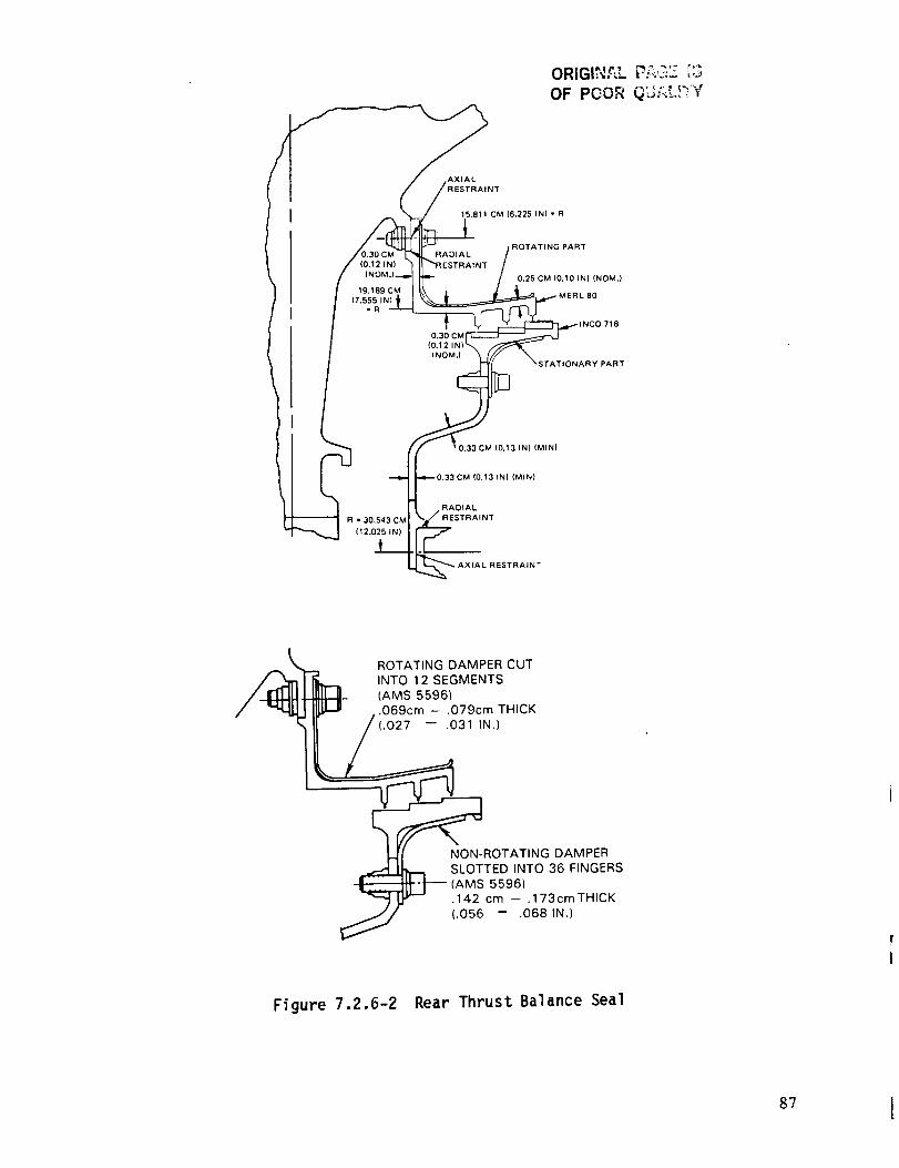
ORIGINf_L P?;,_Z ['3
OF POOR QL.:iLL)'YY
AXIAL
19.189 CM
(7.555 IN)
-R
15.811 CM (6.225 IN) - R
ROTATING PARTRADIAL
0.25 CM 10.10 INI (NOM,)
0.30 CM
INOMJ
) 718
NARYPART
R = 30.543 CM
(12.025 IN)
(0.13 IN) (MINI
(0,13 INI (MIN}
RADIAL
AINT
AXIAL RESTRAINT
/_ ROTATING DAMPER CUT
INTO 12 SEGMENTS,1_--II- (AMS 5596)
,ILL" .069cm - .0719/N.)THICK
NON-ROTATING DAMPERSLOTTED INTO 36 FINGERS
(AMS 5596).142 cm -- .173cmTHICK
(.056 -- .068 IN.)
Figure 7.2.6-2 Rear Thrust Balance Seal
87 I
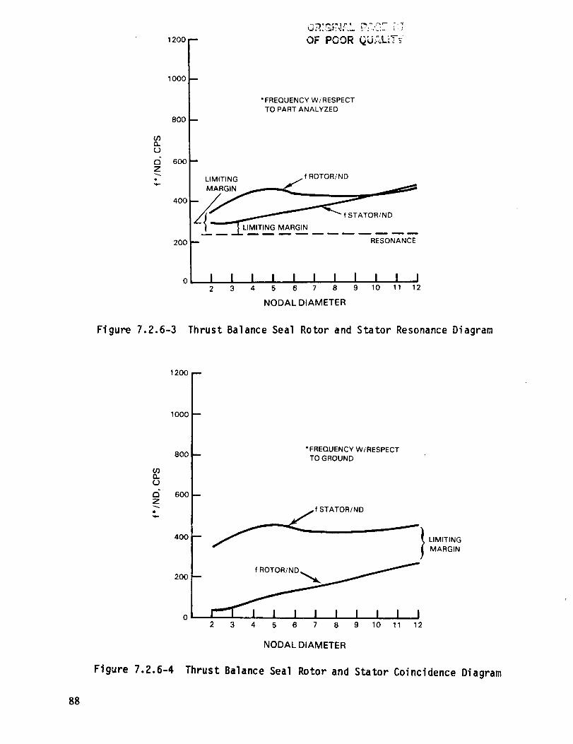
oOnO
Z-,...
1200
1000
800
- OF POOR ..... _'_-_"
m
• FREQUENCY W/RESPECT
TO PART ANALYZED
600 --
,oo UM,T NG
/ | LLIMITING MARGIN
200 I RESONANCE
o I I I I I I I I i ! i2 3 4 5 6 7 8 9 10 11 12
NODAL DIAMETER
Figure 7.2.6-3 Thrust Balance Seal Rotor and Stator Resonance Diagram
1200 --
nU
Z
1000
8OO
600
400
200
"FREQUENCY W/RESPECT
TO GROUND
f STATOR/ND _"" I
2 3 4 5 6 7 8 9 10 11 12
LIMITING
MARGIN
NODAL DIAMETER
Figure 7.2.6-4 Thrust Balance Seal Rotor and Stator Coincidence Diagram
88

OR_GINF, L P;,CZ ;3
OF POOR QUALITY
RADIAL
R = 11.32 CM (4.46 IN)
0.317 CM (0.125 IN) MIN
AXIAL RE_:
0.48 CM (0.19 IN) MIN)
:rOTATING KNIFE-EDGE
INCO 718
STATIONARY PART
0.241 CM (0.095 IN) NOM.)
0.241 CM (0.095 IN) NOM.
DIAL RESTRAINT
R = 19.50 CM (7.68 IN)
RESTRAINT
SPLIT RING DAMPERS
(AMS 5699)
.229cm-.234cm DIA
(.090 IN.-.092 IN.)
BUFFER AIR SEAL
(PWA 1003)
Figure 7.2.6-5 Number 4 Bearing Buffer Seal Assembly
89

,.-.r_,_ _;._iL _":"OF r_'_. "''
1600 F
1400 F
1200
1000
03
(..)
d 6ooZ
600
400
200
0
*FREQUENCY W/RESPECT
TO PART ANALYZED
i LIMITING
MARGIN _
_ '_'_ f ROTOR/ND
ATOR/ND
I -- " M--ARG N......
2 3 4 5 6 7 8 9 10 11 12
NODAL DIAMETER
Figure 7.2.6-6 Number 4 Bearing Buffer Seal Rotor and Stator Resonance Diagram
9O
1600 --
1400--
1200 m
1000 --03
d 800
600 F
400 F
200 F
O--
f ROTOR/ND
LIMITING
MARGIN STATOR/ND
*FREQUENCY W/RESPECT
TO GROUND
I I I I I I 1 I I ! t l2 3 4 5 6 7 8 9 10 11 12
NODAL DIAMETER
Figure 7.2.6-7 Number 4 Bearing Buffer Seal Rotor and Stator CoincidenceDiagram
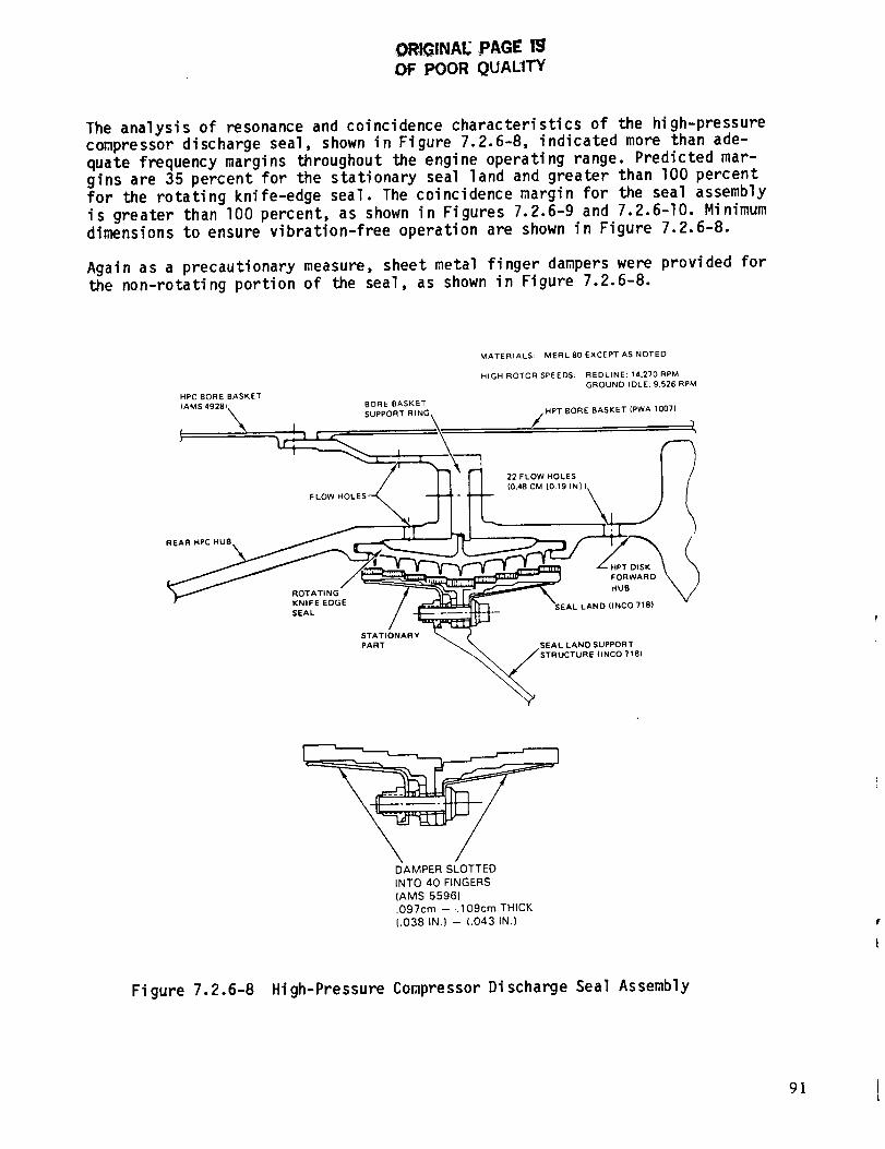
ORIGINAE ,PAGE lg
OF POOR QUAL1TY
The analysis of resonance and coincidence characteristics of the high-pressurecompressor discharge seal, shown in Figure 7.2.6-8, indicated more than ade-
quate frequency margins throughout the engine operating range. Predicted mar-gins are 35 percent for the stationary seal land and greater than lO0 percent
for the rotating knife-edge seal. The coincidence margin for the seal assembly
is greater than 100 percent, as shown in Figures 7.2.6-9 and 7.2.6-I0. Minimum
dimensions to ensure vibration-free operation are shown in Figure 7.2.6-8.
Again as a precautionary measure, sheet metal finger dampers were provided for
the non-rotating portion of the seal, as shown in Figure 7.2.6-8.
MATERIALS: MERL 80 EXCEPT AS NOTED
HIGH ROTOR SPEEDS: REDLINE; 14.270 RPM
GROUND IDLE; 9.526 RPM
HPC BORE BASKET
AMS 4928
\ ,, .. ,,TBOREBASKET(PWA 1007}
FL / I I I I 22 FLOW HOLES I /
STATIONARY _
DAMPER SLOTTED
INTO 40 FINGERS
(AMS 5596)
.097cm -- .109cm THICK
(.038 IN.) -- (.043 IN.)
Figure 7.2.6-8 High-Pressure Compressor Discharge Seal Assembly
9]
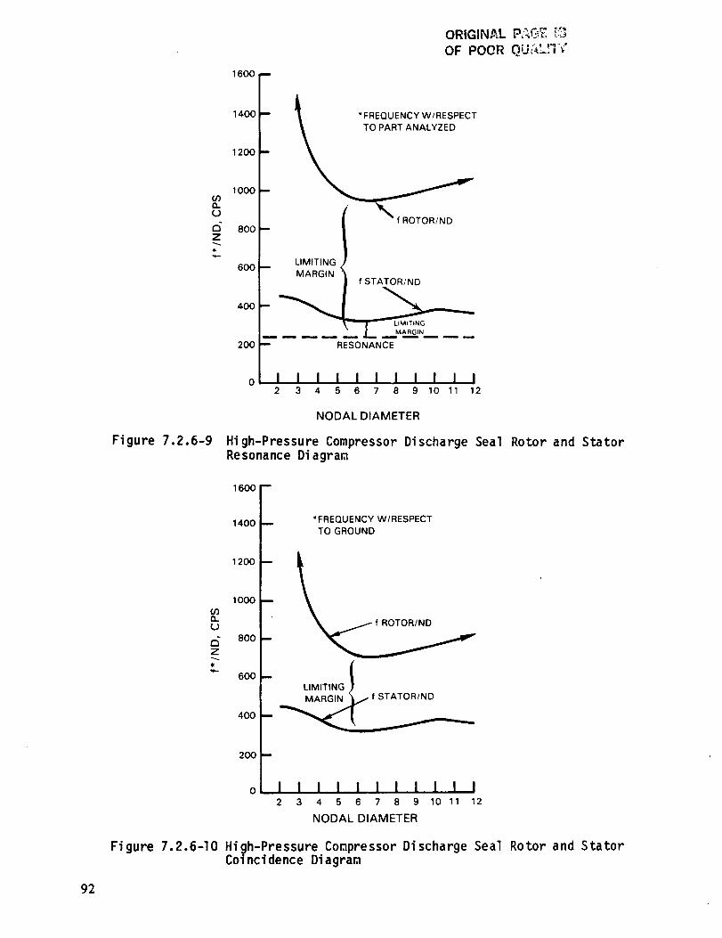
ORIGINAL " _
OF POOR _u_,_-,,
"FREQUENCY W/RESPECT
TO PART ANALYZED
1000
d 800Z
600
400
200
LIMITINGB
MARGIN
f ROTOR/ND
f STATOR/ND
RESONANCE
I i i i I I I I i i i2 3 4 5 6 7 8 9 10 11 12
NODAL DIAMETER
Figure 7.2.6-9 High-Pressure Compressor Discharge Seal Rotor and StatorResonance Diagram
1600 f
1400 *FREQUENCY W/RESPECTTO GROUND
1,oo[1000
.
800
L 600 B {LIMITING )
f STATOR/ND400
200
I I I I I I I I I I I2 3 4 5 6 7 8 9 10 11 12
NODAL DIAMETER
Figure 7.2.6-I0 High-Pressure Compressor Discharge Seal Rotor and StatorCoi ncidence Diagram
92

OF POOR QU_U'I'V"
7.3 VANE AND INNER CASE
7.3.1 General Description
The vane and inner case assembly is illustrated in Figure 7.3.1-I. The primary
elements are the vanes and the vane support structure, the tangential on-board
injection (TOBI) system, and the high-pressure compressor discharge seal sup-
port structure. Design details relating to these elements are described in the
following sections.
HIGH PRESSURE (4.0 IN)
COMPRESSORDISCHARGE SEAL
6.0 CM (2.4 IN)
19.5 CM (7.7 IN)R
3.0CM (1.2 IN)
0,5 cry1
(0.2 IN)
SYSTEM
NOTE: DIMENSIONS ARE NOMINAL. 6.8 CM
RADII ARE MEASURED FROM (2.7 IN}
ENGINE CENTERLINE
32.5 CM
(12.8 IN) R
iVANE INNER
SUPPORT
40,8 CM
16.1 IN)R
Figure 7.3.1-I High-Pressure Turbine Vane and Inner Case Mechanical Design
7.3.2 Vanes
7.3.2.1 Mechanical Design Features
The turbine vane assembly, shown in Figure 7.3.2-I, comprises 24 vanes sup-
ported at the outer surface by bolts through the two holes in the outer flange.These bolts absorb the radial loads as well as provide circumferential re-
straint. This avoids excessive torque loads at the inner support structure and
improper loading of the diffuser case struts. To minimize leakage caused byvane twisting, both the inner and outer surfaces are clamped along a chordal
cut. By having a chordal cut, axial tilting of the vane, introduced by differ-
ential axial growth between the inner case and outer combustor case, is allow-
ed to occur without binding up or opening a leak path.
Vane platforms are sealed by feather seals inserted into various slots on the
platform surfaces, as shown in Figure 7.3.2-2, to prevent leakage of compressordischarge air into the turbine flowpath. Results from the leakage supporting
technology program were incorporated in the design by minimizing feather seal
slot intersections, plugging end gaps, and controlling slot straightness.
93

I.D. CLAMP
O°D,
UPPORT
CHORDAL'CU_
I
LOAD REACTIONS
Figure 7.3.2-1 Turbine Vane Assembly
'W' SEAL
F
COMBUSTOR BAND /
M_CLE3ANCE I'D" SUPPORT
_ CHORDAL CONTACT
CHORDAL
CONTACT
O,D. CLAMP
94
Fi gure 7.3.2-2 Design Approach to Vane Leakage Control
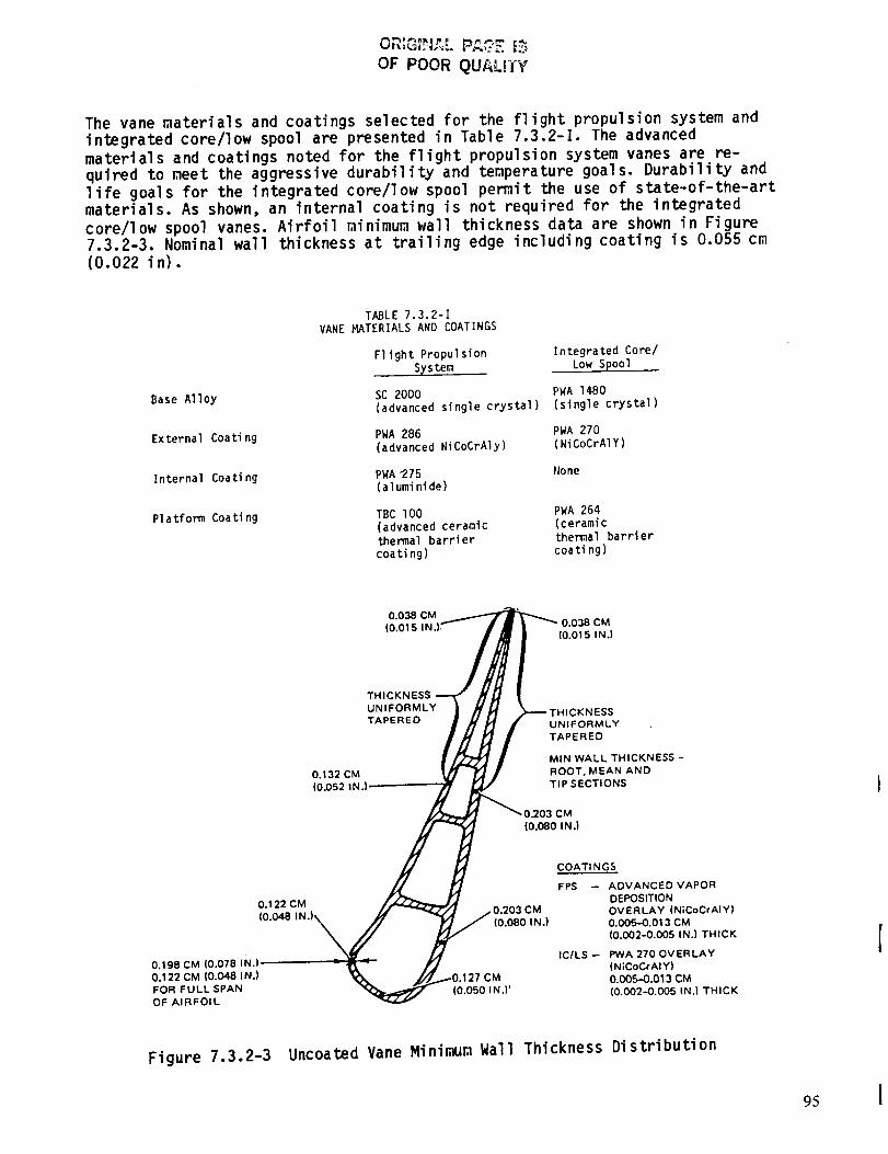
OF POOR QUALITY
The vane materials and coatings selected for the flight propulsion system and
integrated core/low spool are presented in Table 7.3.2-I. The advanced
materials and coatings noted for the flight propulsion system vanes are re-quired to meet the aggressive durability and temperature goals. Durability and
life goals for the integrated core/low spool pemit the use of state-of-the-art
materials. As shown, an internal coating is not required for the integrated
core/low spool vanes. Airfoil minimum wall thickness data are shown in Figure
7.3.2-3. Nominal wall thickness at trailing edge including coating is 0.055 cm(0.022 in).
Base Alloy
External Coating
Internal Coating
Platform Coating
TABLE 7.3.2-I
VANE _TERIALS AND COATINGS
Flight Propulsion Integrated Core/
STstem Low Spool
SC 2000 PWA I¢B0
(advanced single crystal) (single crystal)
PWA 286 PWA 270
(advanced NiCoCrAly) (NiCoCrAIY)
PWA 275 None
(aluminide)
TBC 100 PWA 264
(advanced ceramic (ceramic
thermal barrier themal barrier
coating) coating)
O.O38 CM(0.015 0.038 CM
(0.015 IN.)
THICKNESS
UNIFORMLYTAPERED
0.132 CM
(0.052 IN.l:
:KNESS
UNIFORMLYTAPERED
MIN WALL THICKNESS -
ROOT, MEAN ANDTIP SECTIONS
0.122 CM203 CM
(0.080 IN.)
0.198 CM (0.078 IN.) r
0.122 CM (0.048 IN.) CM
FOR FULL SPAN (0.050 IN,] )OF AIRFOIL
COATI NGS
FPS -- ADVANCED VAPOR
DEPOSITIONOVERLAY (NiCoCrAIY)0.005-0.013 CM
(0.002-0.005 IN.) THICK
ICILS-- PWA 270 OVERLAY(NiCoCrAIY)
0.005-0.013 CM(0.002--0.005 IN.) THICK
Figure 7.3.2-3 Uncoated Vane Minimum Wall Thickness Distribution
95
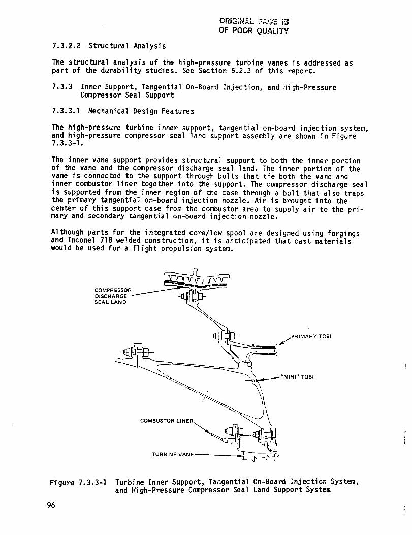
ORi=,r..__L F_,G'_ [_
OF POOR QUALITY'
7.3.2.2 Structural Analysis
The structural analysis of the high-pressure turbine vanes is addressed as
part of the durability studies. See Section 5.2.3 of this report.
7.3.3 Inner Support, Tangential On-Board Injection, and High-Pressure
Compressor Seal Support
7.3.3.1 Mechanical Design Features
The high-pressure turbine inner support, tangential on-board injection system,
and high-pressure conpressor seal land support assembly are shown in Figure7.3.3-I.
The inner vane support provides structural support to both the inner portion
of the vane and the compressor discharge seal land. The inner portion of thevane is connected to the support through bolts that tie both the vane and
inner combustor liner together into the support. The compressor discharge seal
is supported from the inner region of the case through a bolt that also traps
the primary tangential on-board injection nozzle. Air is brought into the
center of this support case froB the combustor area to supply air to the pri-mary and secondary tangential on-board injection nozzle.
Although parts for the integrated core/low spool are designed using forgingsand Inconel 718 welded construction, it is anticipated that cast materials
would be used for a flight propulsion system.
COMPR ESSOR_DISCHARGE
SEAL LAND
I]l ,jPR,MARYTOB,
COMBUSTOR LINER
TURBINE VANE
Figure 7.3.3-I
96
Turbine Inner Support, Tangential On-Board Injection System,
and High-Pressure Compressor Seal Land Support System
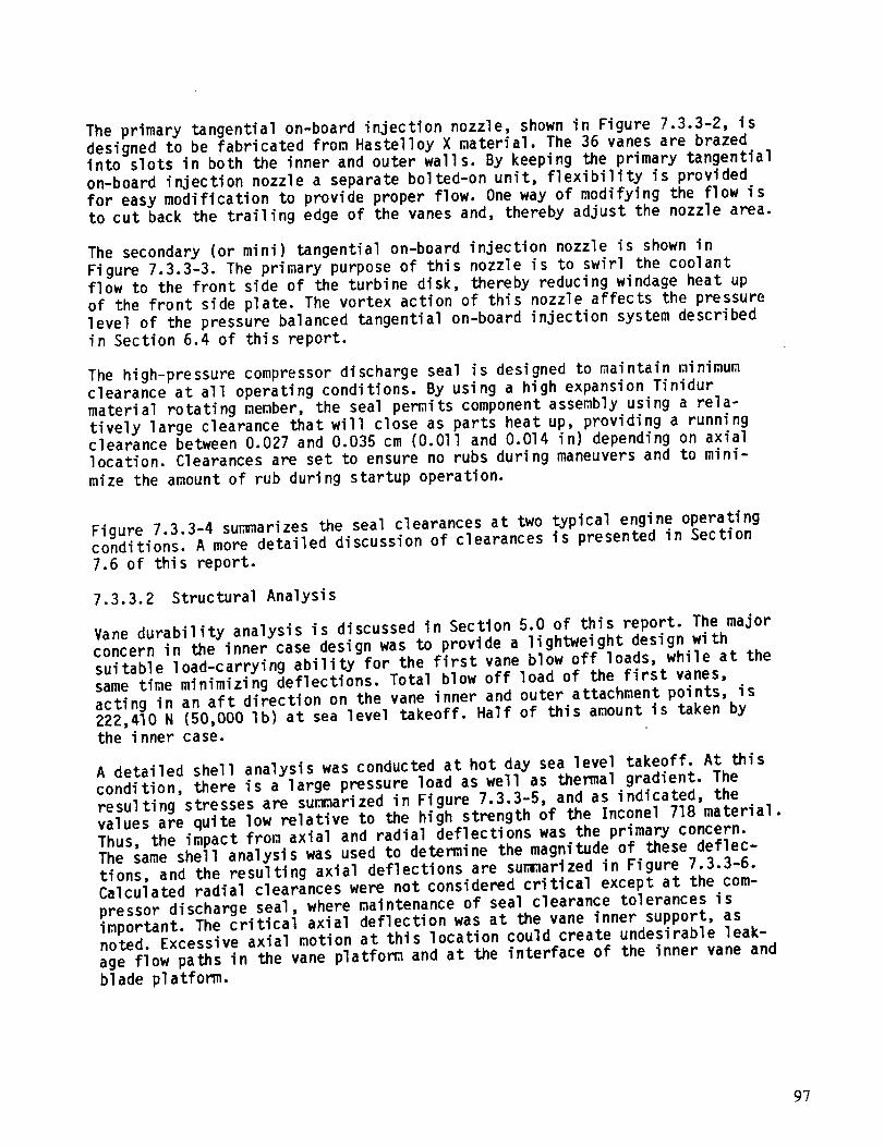
The primary tangential on-board injection nozzle, shown in Figure 7.3.3-2, is
designed to be fabricated from Hastelloy X material. The 36 vanes are brazed
into slots in both the inner and outer wall s. By keeping the primary tangential
on-board injection nozzle a separate bolted-on unit, flexibility is provided
for easy modification to provide proper flow. One way of modifying the flow isto cut back the trailing edge of the vanes and, thereby adjust the nozzle area.
The secondary (or mini) tangential on-board injection nozzle is shown in
Figure 7.3.3-3. The primary purpose of this nozzle is to swirl the coolant
flow to the front side of the turbine disk, thereby reducing windage heat up
of the front side plate. The vortex action of this nozzle affects the pressure
level of the pressure balanced tangential on-board injection system describedin Section 6.4 of this report.
The high-pressure compressor discharge seal is designed to maintain minimum
clearance at all operating conditions. By using a high expansion Tinidur
material rotating member, the seal permits component assembly using a rela-
tively large clearance that will close as parts heat up, providing a runningclearance between 0.027 and 0.035 cm (O.Oll and 0.014 in) depending on axial
location. Clearances are set to ensure no rubs during maneuvers and to mini-
mize the amount of rub during startup operation.
Figure 7.3.3-4 summarizes the seal clearances at two typical engine operatingconditions. A more detailed discussion of clearances is presented in Section
7.6 of this report.
7.3.3.2 Structural Analysis
Vane durability analysis is discussed in Section 5.0 of this report. The major
concern in the inner case design was to provide a lightweight design with
suitable load-carrying ability for the first vane blow off loads, while at the
same time minimizing deflections. Total blow off load of the first vanes,
acting in an aft direction on the vane inner and outer attachment points, is222,410 N (50,000 Ib) at sea level takeoff. Half of this amount is taken bythe inner case.
A detailed shell analysis was conducted at hot day sea level takeoff. At this
condition, there is a large pressure load as well as thermal gradient. The
resulting stresses are sumarized in Figure 7.3.3-5, and as indicated, the
values are quite low relative to the high strength of the Inconel 718 material.
Thus, the impact from axial and radial deflections was the primary concern.The same shell analysis was used to determine the magnitude of these deflec-
tions, and the resulting axial deflections are summarized in Figure 7.3.3-6.
Calculated radial clearances were not considered critical except at the com-
pressor discharge seal, where maintenance of seal clearance tolerances isimportant. The critical axial deflection was at the vane inner support, asnoted. Excessive axial motion at this location could create undesirable leak-
age flow paths in the vane platfor_ and at the interface of the inner vane and
blade platform.
97
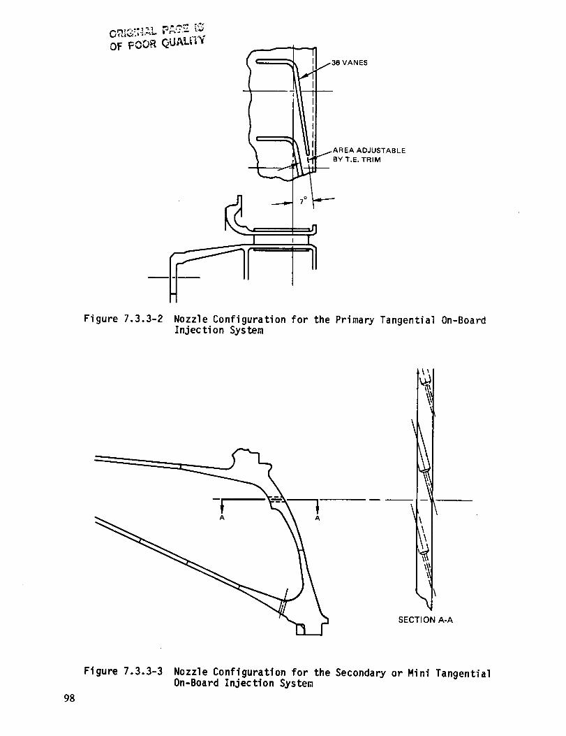
OF POOR QUALITY
I _AREA ADJUSTABLE
Figure 7.3.3-2 Nozzle Configuration for the Primary TangentialInjection System
0n-Board
\\
SECTION A-A
98
Figure 7.3.3-3 Nozzle Configuration for the Secondary or Mini Tangential0n-Board Injection System

• MIN. ASSEMBLY CLEARANCE
OF 0.038 CM (0.015 IN)
• DESIRED SLTO CLEARANCE
OF 0.0317 CM (0.0125 IN)
• NO RUB AT MANEUVER
0.0193 CM (0.0076 IN)
• RESULTS
OF POOR QUALITY
®
(9 @ @COLD GAP 0.043 CM (0.017 IN) 0.073CM (0.029 IN) 0.040 CM (0.016 IN)PINCH PT _60 SEC. DECEL. _ 10-12 SEC. ACCEL, _" 80 SEC. DECEL,AVG GAP @:
• ADP 0.030 CM (0.012 IN) 0.035 CM (0.014 IN) 0,027 CM (0.011 IN)• SLTO 0.0317 CM (0.0125 IN) _-
Figure 7.3.3-4 High-Pressure Compressor Discharge Seal Clearance Sugary
FELT METAL
344.740 MPa
27.579 MPa
96.527 MPa (14 KSI)
(INCONEL X)
• STRESS LEVELS RELATIVELY LOW
• CONTROL AND LIMIT AXIAL
AND RADIAL DEFLECTIONS
206.844 MPa (30 KSl)
HASTELLOY X)
296.476 MPa (43 KSI)
461.952 MPa (67 KSI)
(INCONEL 718)
@ SLTO HOT DAY
<206.844 MPa (30 KSI)
48.264 MPa
(7 KSI)
358.530 MPa
(52 KSI)
i193.054 MPa (28 KSI)
HOOP (WASPALOY) ®
Figure 7.3.3-5 Inner Vane Case Stress Summary
99
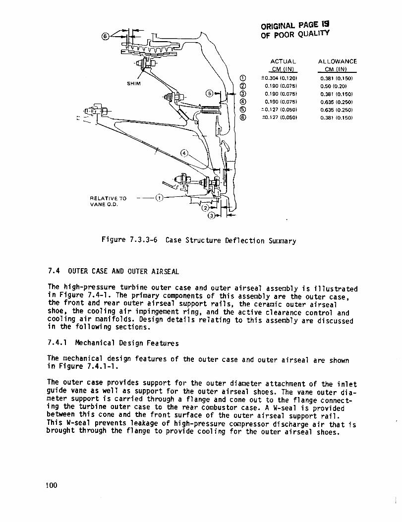
ORIGINAL PAGE |_1
OF POOR QUAL1TY
SHIM
ACTUA L A L LOWANCE
CM (IN) CM (IN I
(_ ---0.304 (0.120) 0.381 (0.150)
(_) 0.190 (0,075) 0.50 (0.20)
(_) 0.190 (0.075) 0.381 (0.150)
(_ 0.190 (0.075) 0.635 (0.250)
(_) ---0.127 (0.050) 0.635 (0.250)
(E) +0.127 (0.050) 0.381 (0.150)
RELATIVE TO ---- _1)"VANE O.D.
Figure 7.3.3-6 Case Structure Deflection Sur.lmary
7.4 OUTER CASE AND OUTER AIRSEAL
The high-pressure turbine outer case and outer airseal assembly is illustrated
in Figure 7.4-I. The primary components of this assembly are the outer case,the front and rear outer airseal support rails, the ceramic outer airseal
shoe, the cooling air impingement ring, and the active clearance control and
cooling air nanifolds. Design details relating to this assembly are discussedin the following sections.
7.4.1 Mechanical Design Features
The mechanical design features of the outer case and outer airseal are shownin Figure 7.4.1-I.
The outer case provides support for the outer diameter attachment of the inlet
guide vane as well as support for the outer airseal shoes. The vane outer dia-
meter support is carried through a flange and cone out to the flange connect-
ing the turbine outer case to the rear combustor case. A W-seal is providedbetween this cone and the front surface of the outer airseal support rail.
This W-seal prevents leakage of high-pressure compressor discharge air that isbrought through the flange to provide cooling for the outer airseal shoes.
I00
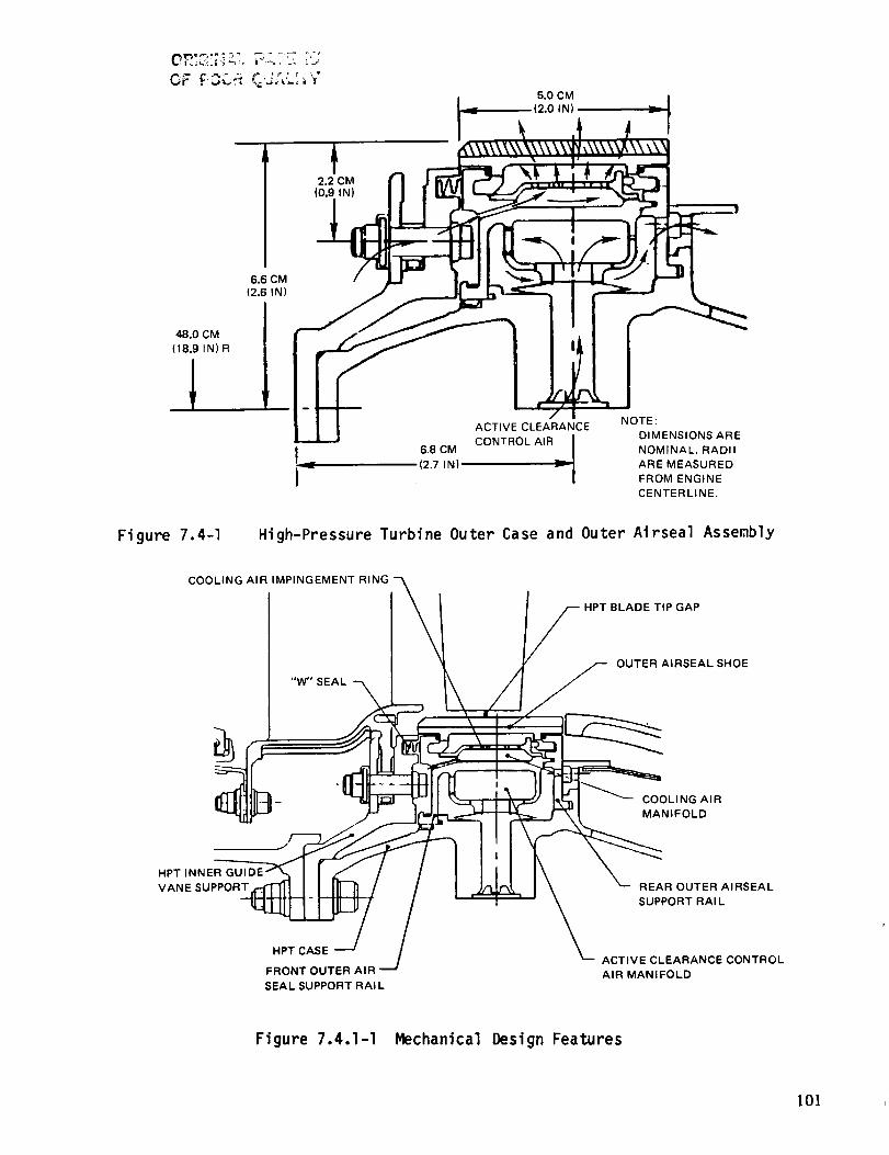
OF F3CR +,+
2.2 CM(0.9 IN)
5.0 CM
(2.0 IN)
6.6 CM
(2.6 IN)
48.0 CM
(18.9 IN) R
ACTIVE CLEARANCE
I_ 6.8 CM CONTROL AIR_I_ (2.7 IN) ..
Figure 7.4-1 High-Pressure Turbine Outer Case and
COOLING AIR IMPINGEMENT RINE
"W" SEAL
NOTE:
DIMENSIONS ARE
NOMINAL. RADII
ARE MEASURED
FROM ENGINE
CENTERLINE.
Outer Airseal Assembly
HPT BLADE TIP GAP
OUTER AIRSEAL SHOE
COOLING AIR
MANIFOLD
HPT INNER
VANE SUPPORT
HPT CASE
FRONT OUTER AIR
SEAL SUPPORT RAI L
REAR OUTER AIRSEAL
SUPPORT RAI L
ACTIVE CLEARANCE CONTROLAIR MANIFOLD
Figure 7.4.1-I Mechanical Design Features
lOl

An internal active clearance control system is used for optimizing blade tipclearance during all engine operating conditions. This is accomplished byimpinging controlled temperature air on the outer airseal support rails(Figure 7.4.1-1) to move the blade outer air seal shoes radially. Temperaturesof the rear and front rails are kept stmilar for uniform deflection of bothrails. The controlled temperature air enters the active clearance controlmanifold through eight bosses in the high-pressure turbine case, flows throughholes in the active clearance control manifold to impinge on the outer airsealsupport ratls, and axtally discharges through holes in the rear outer airsealsupport rail to an annulus between the hot strut outer diameter fairing andthe high-pressure turbine case. Further discussion of the active clearancecontrol system is contained in Section 7.5 of this report.
The blade outer airseal shoe, shown in Figure 7.4.1-2, features a ceramiccoating 0.327 cm (0.129 in) thick over a PWA 655 (cast Inconel 713) shoenominally 0.254 cm (0.100 in) thick. Slots in the shoe reduce its spring rate.This prevents the ceramic material from being overstressed as it cools follow-ing engine transient operation.
To minimize cooling air leakage, W-seals are also used on the front and rearhook areas of the shoe and feather seals ape used at the circumferential shiplap joint between shoes. The ship lap protects the feather seals from pressurepulses caused by the passing blades and serves as a backup (but less effective)seal. It also prevents a large step between shoes in the event of a blade rub.If one end of a shoe deflects due to a rub, the ship lap will force the end ofthe next adjacent shoe to deflect equally and simultaneously.
The shoes are held radially inward by the pressure differential across the
shoes. Vibrations are damped by a combination of the axial spring load applied
by the W-seals, pressure loadings and metal-to-metal contact in the ship lapand feather seal areas.
High-pressure compressor discharge air cools the outer airseal shoes (Figure
7.4.1-I). Air is metered through holes in the inlet guide vane support, passesthrough holes in the front outer airseal support rail to the cooling air mani-
fold, then flows through radial holes in a circumferential impingement ring tocool the outer diameter of the outer airseal shoes.
After the outer alrseal shoes are cooled, portions of the air flow to three
different areas. The majority of the air flows through holes at one circumfer-
ential end of the shoes into the gap between shoes to prevent intrusion of gas
path air into the gap and to lower the metal and ceramic temperatures adjacent
to the gap. A small amount of the air leaks past the W-seals located between
the outer airseal shoes and the support rails. Some of the air passes through
axial holes in the hook area of the rear outer airseal support rail to main-
tain the temperature of the rear rail the same as that of the front rail.
The materials used in the outer case and outer airseal assembly are shown in
Figure 7.4.1-3. Waspaloy and Inconel 718 materials were selected for the case
wall and the common wall between the cooling air and active clearance control
manifolds to provide the required dynamic resistance to satisfy the bladecontainment criteria, while maintaining an acceptable material thickness.
The ceramic is an abradable yttrium stabilized zirconia. The development goal
is for lO:l abradable volume ratio with grit imbedded blade tips.
102
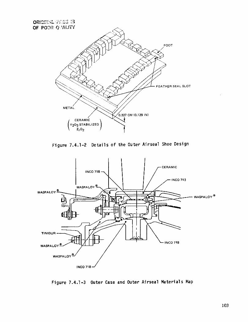
FOOT
FEATHER SEAL SLOT
METAL
CERAMIC )Y203 STABILIZED
ZrO 2
).327 CM (0.129 IN)
Figure 7.4.1-2 Details of the Outer Airseal Shoe Design
WASI
WA
INCO 718
INCO 713
WASPALOY
TINIDUR
WASPALOY
WASPA LOY
INCO 718
INCO 718
Figure 7.4.1-3 Outer Case and Outer Airseal Materials Map
103

7.4.2 Structural Analysis
OF POOR QUALr_I
Structural analysis of this assembly was accomplished through the use of the
shell analysis model shown in Figure 7.4.2-I. This model includes pressure
loadings, vane and shoe support reactions, and thermal gradients based on asteady-state sea level takeoff, hot day engine operating condition. Static
pressures are shown in Figure 7.4.2-I and the metal temperature distribul;ionis shown in Figure 7.4.2-2.
Typical stresses resulting from this analysis are shown in Figure 7.4.2-3. All
are well below allowables at the assumed steady-state condition, thereby
satisfying both flight propulsion system and integrated core/low spool designrequirements.
.... AMBIENT PRESS.
VANE LOAD
OAS LOAD
_ OAS LOAD
LOAD
E_ STATIC PRESS. - % PT3
Figure 7.4.2-1 Shell Analysis Model
7.5 ACTIVE CLEARANCE CONTROL SYSTEM
Large turbine blade operating clearances have a deliterious affect on componentefficiency, and consequently a negative impact on overall system fuel consump-
tion. The goal, therefore, is to maintain tip clearances as close as possible,while avoiding rubs during normal operating conditions.
Since the high-pressure turbine in the Energy Efficient Engine is a high per-
formance system, blade tip clearances are designed for minimum leakage. Theoal blade tip clearances are 0.068 cm (0.027 in) at takeoff and 0.047 cm
0.0186 in) at cruise (the aerodynamic design point). To achieve optimum
clearances during all flight conditions, the high-pressure turbine is designedwith an active clearance control system.
104

o C (OF) FOR STEADY STATE - SLTO - 28°C {84°F) DAY
WITH 15TH STAGE ACC AIR
I (1170°F)
I
1105°F)
783°C (1442 (1119°F) (1110°F)
(1147%)
(1114%)
• 535°C (995°F)
530 ° C
552°C (1027°F)
498 °(3 (929 °F
501 °C (935°F
499°C (931°F
539°C (1003 ° F)
(997°F)
_(965°F)
°C (1257 °F)
518 °C (966 °F)
515°C (959%)
Figure 7.4.2-2 Ter,lperature Map
STEADY STATE - SLTO - 28°C (84°F) DAY WITH 15TH STAGE ACC AIR
G H = .,t19.632 MPa (-13 KSI
O H = -179.265 MPa ('26
i
o B = -+ 586.058 MPa (-+185 KSI) --_
o H =-351.635 MPa (-51 KS!
O H =.-227.528 MPa (-33 KSI)
O H = -193.054 MPa (-28 KSI)
= -151.686 MPa (-22 KS1}
O H = 158.580 MPa (23 KSI)
(7 8 = + 448.162 MPa (+ 65 KS! )
OH = 158.580 MPa (23 KSI)
(7 H = 220.634 MPa (32
O H = 275,792 MPa (40
o H = 289.582 MPa (42 KSI
OH = 213.739 MPa (31 KSI)
o"6 _ + 186.160 MPa (+27 KSI)
(7 H = 48.264 MPa (7 KSI)
o H = 165.475 MPa (24 KSI)
H = 131.001 MPa (19 KSI)
o H = 193.054 MPa (28 KSI)
= -+ 206.844 MPa (+ 30 KSI)
o H = 275.792 MPa (40 KSI)
Figure 7.4.2-3 Stress Map
105
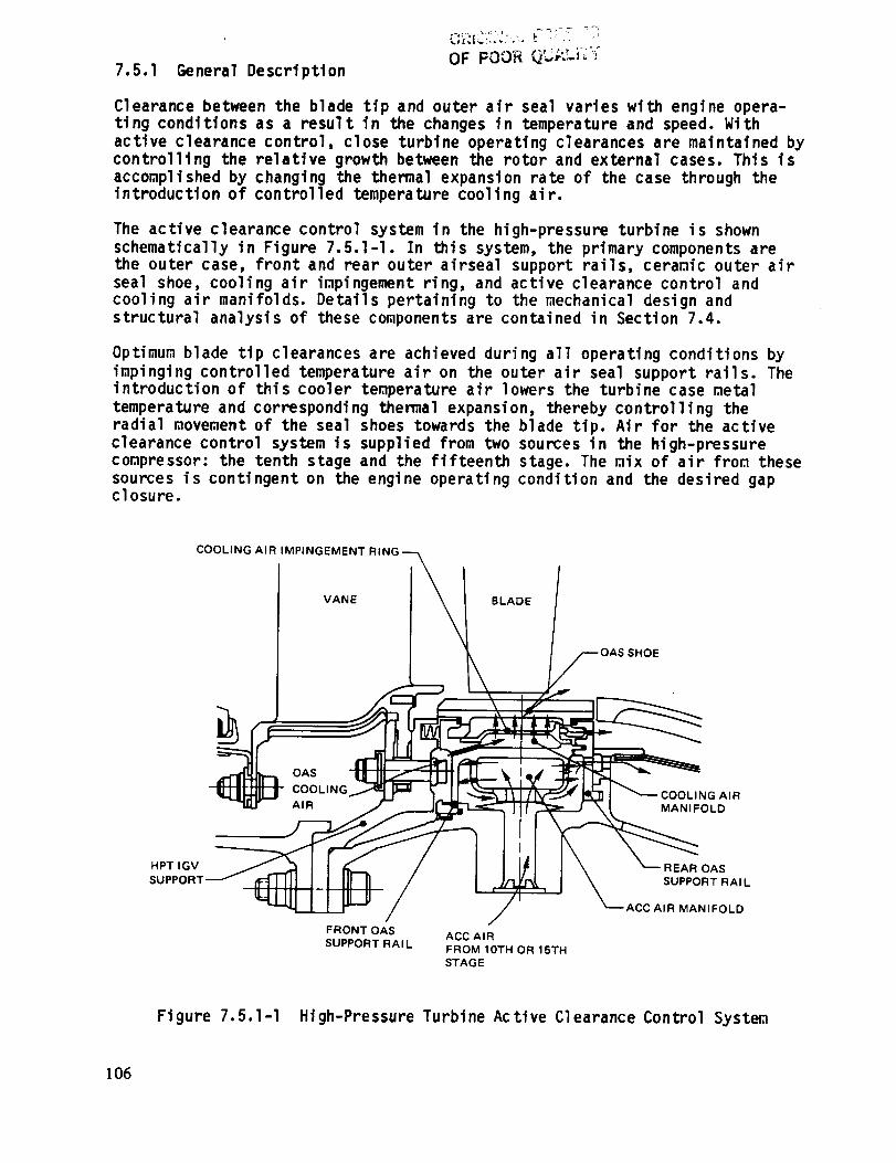
7.5.1 General DescriptionOF POOR V.-,'--' _"
Clearance between the blade tip and outer air seal varies with engine opera-ting conditions as a result in the changes in temperature and speed. With
active clearance control, close turbine operating clearances are maintained by
controlling the relative growth between the rotor and external cases. This is
accomplished by changing the thermal expansion rate of the case through theintroduction of controlled temperature cool ing air.
The active clearance control system in the high-pressure turbine is shown
schematically in Figure 7.5.I-I. In this system, the primary components arethe outer case, front and rear outer airseal support rails, ceramic outer air
seal shoe, cooling air impingement ring, and active clearance control and
cooling air manifolds. Details pertaining to the mechanical design andstructural analysis of these components are contained in Section 7.4.
Optimum blade tip clearances are achieved during all operating conditions by
impinging controlled temperature air on the outer air seal support rails. Theintroduction of this cooler temperature air lowers the turbine case metal
temperature and corresponding themal expansion, thereby controlling the
radial movement of the seal shoes towards the blade tip. Air for the active
clearance control system is supplied from two sources in the high-pressure
compressor: the tenth stage and the fifteenth stage. The mix of air from these
sources is contingent on the engine operating condition and the desired gapclosure.
COOLING AIR IMPINGEMENT RIN,
VANE BLADE
OAS
COOLING DLING AIR
AIR MANIFOLD
HPT IGV REAR OAS
SUPPOF SUPPORT RAI L
FRONT OAS ACC AIR
SUPPORT RAIL FROM 10TH OR 1STH
STAGE
ACC AIR MANIFOLD
Figure 7.5.1-I High-Pressure Turbine Active Clearance Control System
106
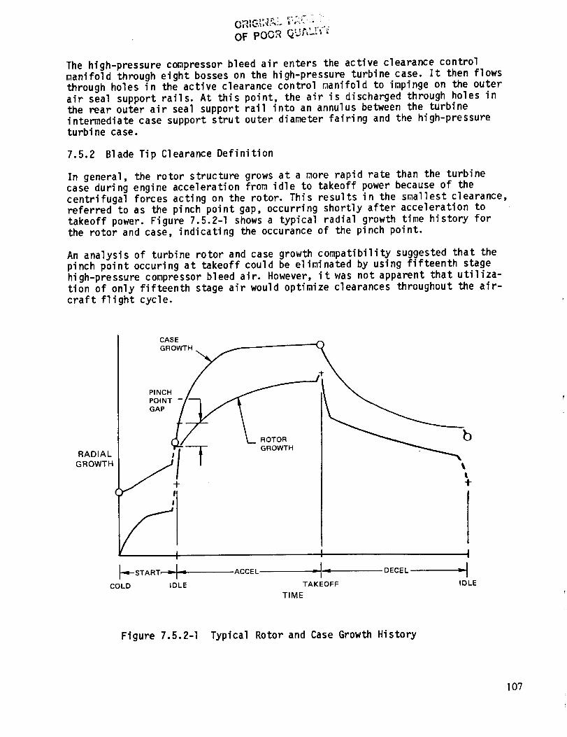
OF pOOR (_'J_"'
The high-pressure compressor bleed air enters the active clearance control
manifold through eight bosses on the high-pressure turbine case. It then flows
through holes in the active clearance control manifold to impinge on the outer
air seal support rails. At this point, the air is discharged through holes in
the rear outer air seal support rail into an annulus between the turbine
intermediate case support strut outer diameter fairing and the high-pressureturbine case.
7.5.2 Blade Tip Clearance Definition
In general, the rotor structure grows at a _ore rapid rate than the turbine
case during engine acceleration from idle to takeoff power because of the
centrifugal forces acting on the rotor. This results in the smallest clearance,referred to as the pinch point gap, occurring shortly after acceleration to
takeoff power. Figure 7.5.2-I shows a typical radial growth time history for
the rotor and case, indicating the occurance of the pinch point.
An analysis of turbine rotor and case growth compatibility suggested that the
pinch point occuring at takeoff could be eliminated by using fifteenth stage
high-pressure co_pressor bleed air. However, it was not apparent that utiliza-
tion of only fifteenth stage air would optimize clearances throughout the air-
craft flight cycle.
RADIAL
GROWTH
CASE
PINCH
/ L .o,o. b
'q-START, _ _ ACCEL _ _'_ DECEL T--
COLD IDLE TAKEOFF IDLE
TIME
Figure 7.5.2-I Typical Rotor and Case Growth History
107
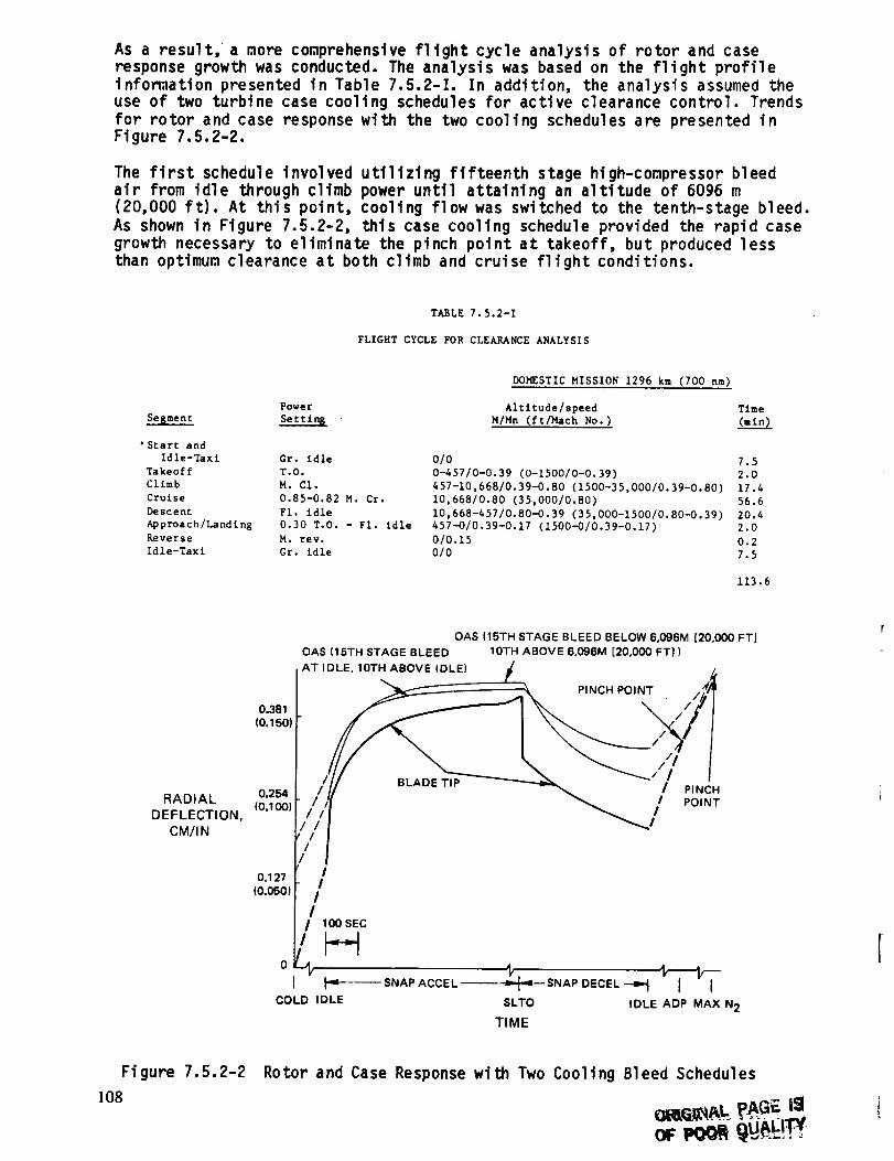
As a result, a more comprehensive fltght cycle analysis of rotor and caseresponse growth was conducted. The analysis was based on the fltght profileinformation presented in Table 7.5.2-I. In addition, the analysis assumed theuse of two turbine case cooltng schedules for active clearance control. Trendsfor rotor and case response with the two cooltng schedules are presented inFlgure 7.5.2-2.
The first schedule involved utilizing fifteenth stage high-compressor bleed
air from idle through climb power until attaining an altitude of 6096 m
(20,000 it). At this point, cooling flow was switched to the tenth-stage bleed.
As shown in Figure 7.5.2-2, this case cooling schedule provided the rapid case
growth necessary to eliminate the pinch point at takeoff, but produced less
than optimum clearance at both climb and cruise flight conditions.
TABLE 7.5.2-I
FLIGHT CYCLE FOR CLEARANCE ANALYSIS
Segment
'Start andIdle-Taxl
Takeoff
Climb
Cruise
Descent
Approach/Landlng
Reverse
Idle-Taxl
DOMESTIC MISSION 1296 km (700 nm)
Power Altltude/speed Time
Settlr_L M/Mn (ft/Haeh No.) (mln)
Gr. idle
T.O.
H. Cl.
0.85-0.82 M. Cr.
FI. idle
0.30 T.O. - FI. idle
M. rev.Gr. idle
010 7.5
0-457/0-0.39 (0-1500/0-0.39) 2.0
457-10,668/0.39--0.80 (1500-35,000/0.39-0.80) 17.4
10,668/0.80 (35,000/0.80) 56.6
10,668-457/0.80-O.39 (35,000-1500/0.80-0.39) 20.4457-O/0.39-0.17 (1500-0/0.39-0.17) 2.0
0/0.15 0.2
0/O 7.5
113.6
O.381
(O.150
RADIAL 0.254(0.100)
DEFLECTION,
CM/I N
0.127
(O.050)
OAS (15TH STAGE BLEED BELOW 6,096M [20,000 FT]
OAS (15TH STAGE BLEED IOTH ABOVE 6,096M [20,000 FT])
AT IDLE, IOTH ABOVE IDLE)
"___: f _ PINCH POINT . ,,_
// x lA
,/ii
I /
!!
!!
! 100 SEC
I,pt-----SNAP ACCEL _-_L'_ SNAP DECEL -_ I I
COLD IDLE $LTO IDLE ADP MAX N2
TIME
Figure 7.5.2-2
]08
Rotor and Case Response with Two Cooling Bleed Schedules
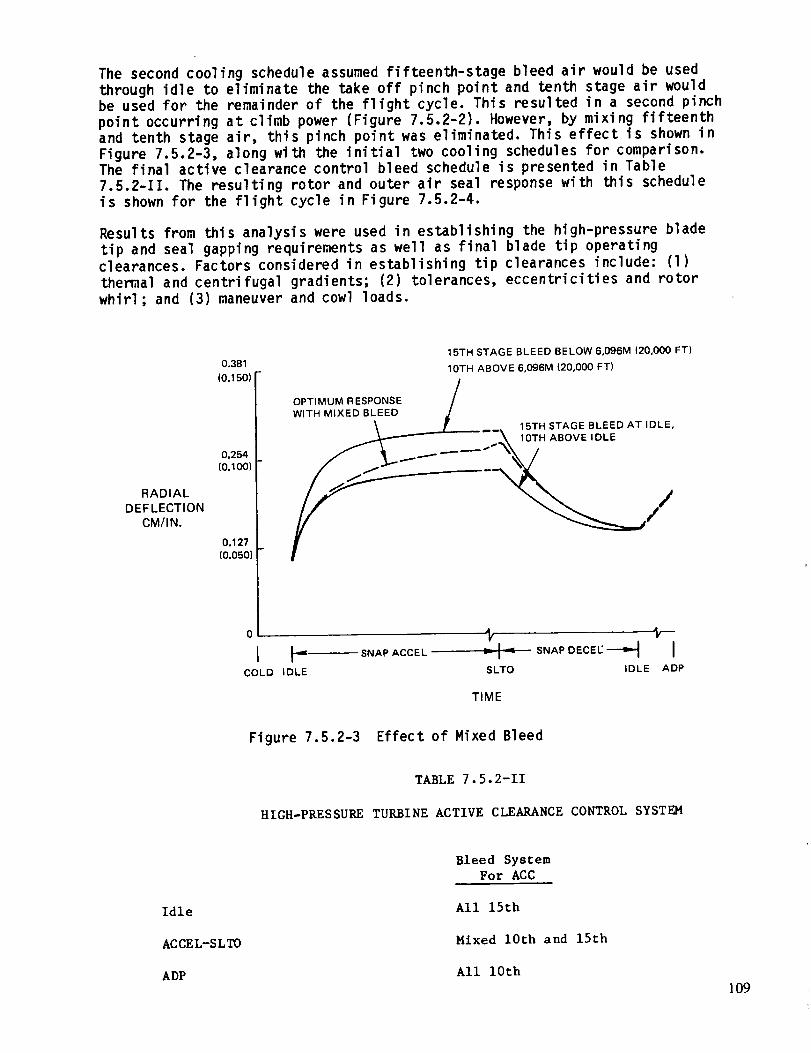
The second cooling schedule assumed fifteenth-stage bleed air would be usedthrough idle to eliminate the take off pinch point and tenth stage air wouldbe used for the remainder of the flight cycle. This resulted in a second pinch
point occurring at climb power (Figure 7.5.2-2). However, by mixing fifteenth
and tenth stage air, this pinch point was eliminated. This effect is shown in
Figure 7.5.2-3, along with the initial two cooling schedules for comparison.The final active clearance control bleed schedule is presented in Table
7.5.2-II. The resulting rotor and outer air seal response with this schedule
is shown for the flight cycle in Figure 7.5.2-4.
Results from this analysis were used in establishing the high-pressure blade
tip and seal gapping requirements as well as final blade tip operatingclearances. Factors considered in establishing tip clearances include: (1)
themal and centrifugal gradients; (2) tolerances, eccentricities and rotor
whirl; and (3) maneuver and cowl loads.
RADIAL
DEFLECTION
CM/IN.
0.381
(0.150)
0.254(0.100)
0.127(0.050)
0
I F" "COLD IDLE
15TH STAGE BLEED BELOW 6,096M (20,000 FT)
10TH ABOVE 6,096M (20,000 FT)
OPTIMUM RESPONSE /
WITH MIXED BLEED _ff ....... 15TH STAGE BLEED AT IDLE,
...\ 10TH ABOVE IDLE
"\/
• SNAP ACCEL
't, lr-,- SNAPDECE--'t I
SLTO IDLE ADP
TIME
Figure 7.5.2-3 Effect of Mixed Bleed
TABLE 7 •5.2-II
HIGH-PRESSURE TURBINE ACTIVE CLEARANCE CONTROL SYSTEM
Idle
ACCEL-SLTO
ADP
Bleed System
For ACC
All 15th
Mixed 10th and 15th
All 10th
109
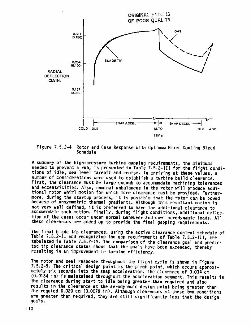
RADIAL
DEFLECTION
CM/I N.
0.381(0.150
0.254(0.100)
0.127(0.050)
ORIGINAL F,_C:_ ;3OF POOR QUALITY
Figure 7.5.2-4 Rotor and Case Response with Optimum Mixed Cooling BleedSchedule
A summary of the high-pressure turbine gapping requirements, the minimums
needed to prevent a rub, is presented in Table 7.5.2-III for the flight condi-
tions of idle, sea level takeoff and cruise. In arriving at these values, anumber of considerations were used to establish a turbine build clearance.
First, the clearance must be large enough to accommodate machining tolerances
and eccentricities. Also, nominal unbalances in the rotor will produce addi-tional rotor whirl motion for which more clearance must be provided. Further-
more, during the startup process, it is possible that the rotor can be bowedbecause of unsymmetric themal gradients. Although this resultant r,mtion is
not very well defined, it is preferred to have the additional clearance to
acconw_odate such motion. Finally, during flight conditions, additional deflec-
tion of the cases occur under nomal maneuver and cowl aerodynamic loads. All
these clearances are added up to provide the final gapping requirements.
The final blade tip clearances, using the active clearance control schedule of
Table 7.5.2-II and recognizing the gap requirements of Table 7.5.2-III, are
tabulated in Table 7.5.2-IV. The comparison of the clearance goal and predic-
ted tip clearance status shows that the goals have been exceeded, thereby
resulting in an improvement in turbine efficiency.
The rotor and seal response throughout the flight cycle is shown in Figure7.5.2-5. The critical design point is the pinch point, which occurs approxi-mately six seconds into the snap acceleration. The clearance of 0.034 cm
(0.O134 in) is maintained throughout the acceleration segment. This results in
the clearance during start to idle being greater than required and also
results in the clearance at the aerodynamic design point being greater thanthe requied 0.020 cm (0.0079 in). Although clearances at these two conditions
are greater than required, they are still significantly less that the designgoal s.
110
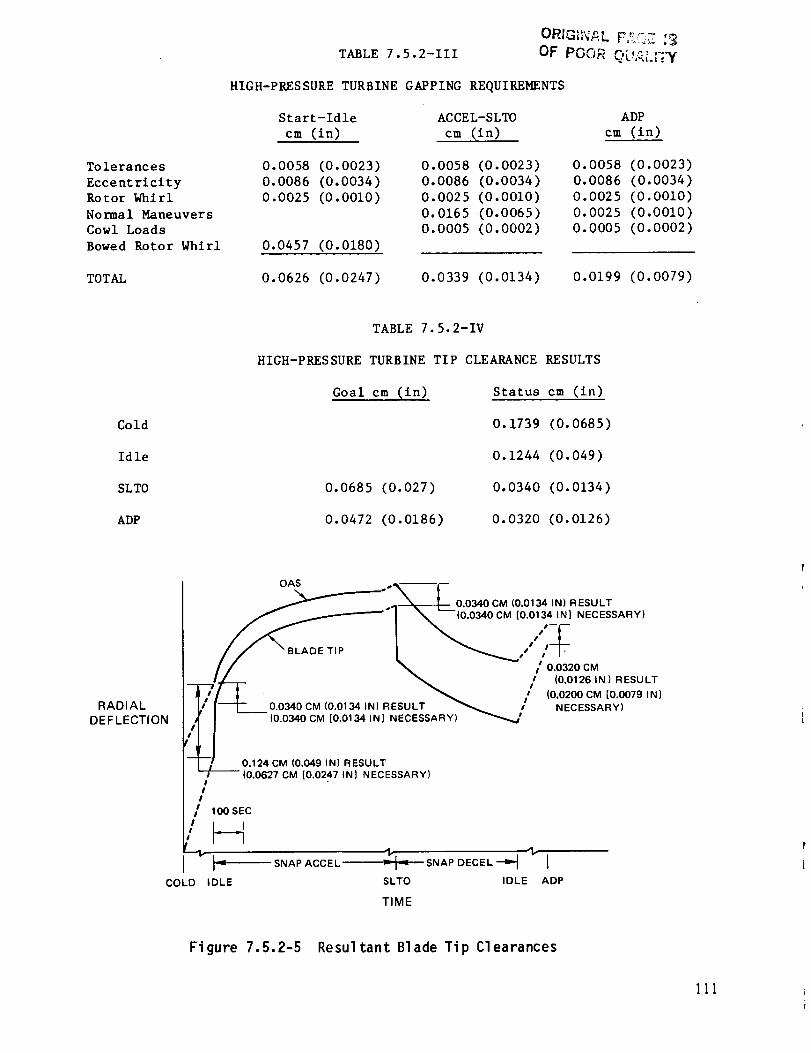
Tolerances
Eccentricity
Rotor Whirl
Normal Maneuvers
Cowl Loads
Bowed Rotor Whirl
TOTAL
TABLE 7.5.2-III OF POOR r,l,_._ "'"
HIGH-PRESSURE TURBINE GAPPING REQUIREMENTS
Start-ldle ACCEL-SLTO
cm (in) cm (in)
0.0058 (0.0023)
0.0086 (0.0034)
0.0025 (0.0010)
0.0457 (0.0180)
0.0058 (0.0023)
0.0086 (0.0034)
0.0025 (0.0010)
0.0165 (0.0065)
0.0005 (0.0002)
0.0626 (0.0247) 0.0339 (0.0134)
ADP
cm (in)
0.0058 (0.0023)
0.0086 (0.0034)
0.0025 (0.0010)
0.0025 (0.0010)
0.0005 (0.0002)
0.0199 (0.0079)
Cold
Idle
SLTO
ADP
TABLE 7.5.2-IV
HIGH-PRESSURE TURBINE TIP CLEARANCE RESULTS
Goal cm (in) Status cm (in)
0.1739 (0.0685)
0.1244 (0.049)
0.0685 (0.027) 0.0340 (0.0134)
0.0472 (0.0186) 0.0320 (0.0126)
RADIALDEFLECTION
OAS .. ----
__"'_ _ _L_Lo.0340 CM (0.0134 IN) R ESU LT
_ I \- (0.0340CM [0.01342N] NECESSARY)
E TIP ,/ /
/ / \ / 0.0320cMI / _ t (0.0126 IN) RESULT
"--[---'t':l_i-- _ / (0 0200 CM [0 0079 IN]
I//-J-O.O ,OCM,O.O,,,N)RESOLT " NECESSARY'
'_2NJ _,ES_L 7 ya (0.0627 CM i0.0247 IN] NECESSAR )
I/
!
/ 100 SEC
/F-I'-" t.,------S.A,,A_CEL
COLD IDLESLTO IDLE ADP
TIME
Figure 7.5.2-5 Resultant Blade Tip Clearances
III
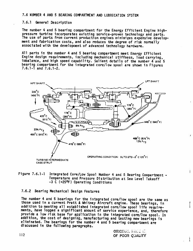
7.6 NUMBER 4 AND 5 BEARING COMPARTMENT AND LUBRICATION SYSTEM
7.6.1 General Description
The number 4 and 5 bearing compartment for the Energy Efficient Engine high-
pressure turbine incorporates existing service-proven technology and parts.
The use of parts from current production engines minimizes expensive develop-
merit and fabrication costs, and also reduces the degree of risk normally
associated with the development of advanced technology hardware.
All parts in the number 4 and 5 bearing compartment meet Energy Efficient
Engine design requirements, including mechanical stiffness, load carrying,imbalance, and high speed capability. Salient details of the number 4 and 5
bearing compartment for the integrated core/low spool are shown in Figures7.6.l-I and 7.6.1-2.
HPT SHAFT
232°C
(450 °F)
1
432°C
(810%)
239(, PT3
490°C (915 ° F)
176 ° C
(350 ° F)
6% PT3
476°C (890°F)
176%
468°C(875°F)
12% PT3
LPT SHAFT
(840 ° F)
TURBINEINTERMEDIATE
CASE STRUT
OPERATING CONDITION: SLTOSTD-3 °C(25°F)
Figure 7.6.1-I Integrated Core/Low Spool Number 4 and 5 Bearing Compartment -
Temperature and Pressure Distribution at Sea Level Takeoff
-3 C (+25OF) Operating Conditions
7.6.2 Bearing Mechanical Design Features
The number 4 and 5 bearings for the integrated core/low spool are the same as
those used in a current Pratt & Whitney Aircraft engine. These bearings, in
addition to meeting all established integrated core/low spool llfe require-merits, have logged a significant amount of service experience, and, therefore
provide a low risk base for application in the integrated core/low spool. In
addition, the cost of designing, manufacturing and testing new bearings iseliminated. The bearings for the number 4 and 5 bearing compartment arediscussed in the following paragraphs.
OR_GL_,cZ_ F_C;Z __i
112 OF POOR QUALITY
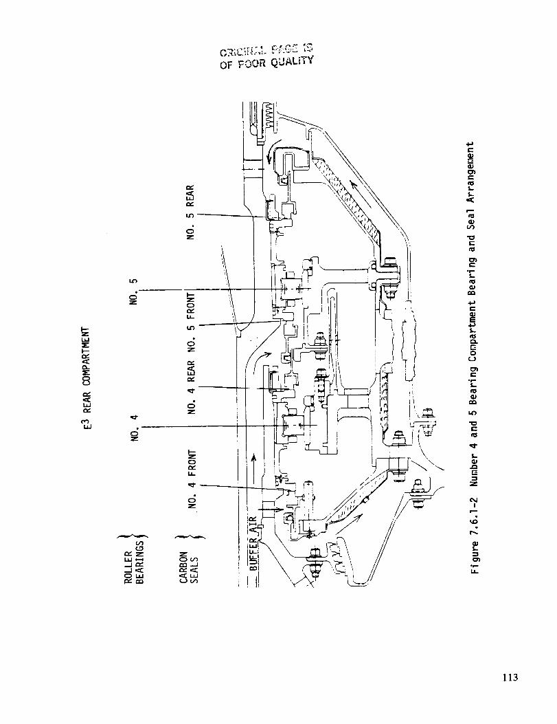
OF _OOR QUALITY
w
I--
o-
8
La.I
Z
Z
_'ZL.LI I--_._l r,,"...J ,_OUJJ
c;z
or_"I.a-
c;z
rv,
.c;z
o
I.a_
c;z
zor..,,")
r_,,_
i
\
e-
e-
e-
i.¢0
e-
E
l.
0
e-i r-
e"
t_
z
I
i
oe,--
113

The number 4 roller bearing for the integrated core/low spool measures 165 mmat the inner diameter and 222 mm at the outer diameter; has 16 na_ diameterrollers and operates at 2.3 X 10⁶ DN. The beartng is oil damped, springcentered, preloaded and under race cooled. The viscous oil damper and softcentering spring are incorporated to satisfy high rotor dynamic responsecriteria. The preloadtng benefit minimizes roller skidding. The under-racecooling feature provides positive cooling to manage themal expansion through-out all operating conditions. 0il flow is 7 kg/min (16 1b/rain) and heat gene-ration is rated at 475,141 J/rain (450 Btu/min). The expected B1 life of thenumber 4 bearing is greater than 500 hours, and the expected BIO life isgreater than 2500 hours. This bearing may have to be optimized to meet flightpropulsion system durability and life requirements.
The integrated core/low spool number 5 bearing is also a 165 mm inner dia-meter, 222 mm outer diameter size bearing, with 16 m diameter rollers, butoperates at much lower speed than the number 5 bearing; 0.64 X 10⁶ DN. Ithas zero preload and reduced internal radial clearance. Its oil flow is 1kg/min (4 lb/mtn) with a heat generation of 31,676 J/rain (30 Btu/min). Aviscous oil film damper has been incorporated on the outer ring to control lowrotor vibratory reponse. Integrated core/low spool life rating for thisbearing is B1 life greater than 10,000 hours and BIO life greater than 50,000hours.
The results of a structural study to determine maximum stress and deflectionare shown in Figure 7.6.2-I.
The number 5 bearing for the flight propulsion system is similar to the number
4 bearing, but with the inner diameter borereduced to 160 mm and the outerdiameter increased to 230 ram.
.P
227,528 MPa (55 KSI)
OF POOR QUALITY
114
Figure 7.6.2-1 Number 4 and 5 Bearing Compartment - Locations of MaximuraStress and Deflection
7.6.3 Seals
The seals used in the number 4 and 5 bearing compartment of the integrated
core/low spool are derived from existing service-proven designs for minimized
risk and decreased cost. The operating environment of the integrated core/low
spool is less severe than that of the existing design. Therefore, the seals
more than adequately meet the life and durability requirements of the
integrated core/low spool.
Carbon seals were selected in place of knife edge seals because of the
increased radial deflection of the high-pressure turbine rotor associated with
the oil-damped number 4 bearing. The resulting large radial gaps would be
detrimental to labyrinth seal operation. Carbon seals minimize the breatherflow and limit total engine oil consumption to 0.22 I/hr (0.06 gal/hr).
The seal arrangement in the number 4 and 5 bearing compartment consists of anumber 4 front carbon seal, an intershaft seal consisting of back-to-back
carbon seals, and a number 5 rear carbon seal. These seals are dry-face, short
carbon with cooled rotating seal plates. Maximum surface rubbing speed is 135
m/sec (445 ft/sec) for the flight propulsion system and 140 m/sec (462 ft/sec)
for the integrated core/low spool, operating in a low-temperature and low-
pressure environment at 68,948 Pa (10 psi) seal pressure drop. Current engineexperience on similar seals has been accumulated at this rubbing speed with
seal pressure drops of 379,214 Pa (55 psi). The integrated core/low spoolseals are derived from existing hardware. The seals used in the flight propul-
sion system feature a high quality carbon grade with excellent durabilitycharacteristics.
To reduce leakage, the low-pressure bearing compartments are buffered by cold
low-pressure compressor air bleed discharge. The system features a single
mainshaft deoiler in the front compartment. Air is introduced to the bearing
compartment between the low and high-speed shafts. The buffering air is bled
from the low-pressure compressor, routed through the center shaft, bled intothe bearing compartment and then discharged through blowdown tubes to the
deoiler in the main compartment. The main feature of this system is the self-regulating design, which eliminates the need for extensive valving and pumps.
Analysis of the seal pressure drop indicates that positive seal pressure can
be obtained at all operating conditions. This positive seal pressure can be
achieved at sea level idle conditions by either reducing the exit bleed flow
or increasing the idle speed.
Integrated core/low spool seal operating conditions are summarized in Table
7.6.3-I. A summary of dry face seal pressure, temperature, and speed experi-
ence is presented in Figure 7.6.3-I.
7.6.4 Lubrication System
The lubrication system for the number 4 and 5 bearing compartment is part of a
system that features positive oil management to provide sufficient cooling andlubrication flow. One of the main features of this system is the self-
regulation arrangement, which eliminates the need for expensive pumps and
extensive plumbing. As a result, the plumbing system is simplified, the sizeand number of scavenge pumps reduced, and the need for a pressure regulatingvalve eliminated.
115

OF POOR QUALITY
Rubbing Speed
plsec (ft/sec)
Seal _p Pa (psi)
Heat Generation
(Stu/mln)
Air Temperature
oc (OF)
TABLE 7.6.3-I
INTEGRATED COP.E/LOW SPOOL SEAL OPERATING CONDITIONS
Hiah Rotor Seals Low Rotor Seals
ADP SLTO IDLE ADP SLTO IDLE
140 (462) 102 (335) 39 (129)
48,263-68948 (7-10) <6894<(1) 20,684 (3)
133 (439)
20,684 (3)
39 (129)
48,263-68,948 (7-10)
131 139 93 26 24
232 (450) Front
Rear232 (450)
426 (800)
It (37)
<6894<( 1 ]
• E 3 IC/LS OPERATING CONDITIONS LESS SEVERE THAN EXPERIENCE
SEAL
PRESSURE
DROP
Pa/PSI
689,480
(1001
551,584(80)
I
413,688 i(60)
275,792
(40)
137,896(20)
91 (300)
454o C (850°F) - 510°C (950°F)
_315°C (600°F)-454 °C (850 ° F)
3710C (700 oF )-398 °C (750 °F )
777-rrr Z
E 3 FPS IC/LS
O x
I I 123:C(45°°FI I,3501 121I 01 137,4501 152I5 1
MAXIMUM RUBBING SPEED - M/SEC (FT/SEC)
Figure 7.6.3-1 Dry Face Seal Pressure, Temperature and Speed Experience
An additional feature of the lubrication system is the blowdown system withoil and air scavenged together through the turbine transition duct strut. Theintegrated core/low spool uses two struts and the design ensures that the oiland air mixture flows through each of the struts without backing up throughthe scavenge lines. This design also eliminates the high cost of installing acomplex internal plumbing arrangement within a single strut. With the plumbingdivided between two struts, the fabrication cost and the associated operation-al risk are substantially reduced.
Oil is transported from the main engine oil pump to two radial oil scoops inthe rear compartment, one scoop servicing the front bearing and the other
servicing the rear. The scoop efficiency for the integrated core/low spool is
60 percent, which is conmensurate with scoop efficiency levels of most current
comercial engines. The scoop arrangement for the flight propulsion system is
being refined for an efficiency increase.
I16
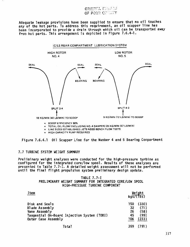
OF"PO07:C::"" .-.-v
Adequate leakage provisions have been supplied to ensure that no oil touchesany of the hot parts. To address this requirement, an oil scupper line has
been incorporated to provide a drain through which oil can be transported away
from hot parts. This arrangement is depicted in Figure 7.6.4-I.
IC/LS REAR COMPARTMENT LUBRICATION SYSTEM
HIGH ROTOR LOW ROTOR
NO. 4 NO. 5
SEAL SEAL SEAL SEAL
G BEAL
SPLIT 3:4
t18 KG/MIN 140 LB/MIN) TO SCOOP
• SCOOP EFFICIENCY 60%
SPLIT 4:3
t5 KG/MIN (12 LB/MIN) TO SCOOP
• TOTAL OIL FLOW (INCLUDING NO. 4 DAMPER) 25 KG/MIN (57 LB/MIN)
• LINE SIZES ESTABLISHED; JETS NEED BENCH FLOW TESTS
• HIGH CAPACITY PUMP REQUIRED
Figure 7.6.4.1 Oil Scupper Line for the Number 4 and 5 Bearing Compartment
7.7 TURBINE SYSTEM WEIGHT SUMMARY
Preliminary weight analyses were conducted for the high-pressure turbine as
configured for the integrated core/low spool. Results of these analyses are
presented in Table 7.7-I. A detailed weight assessment will not be performeduntil the final flight propulsion system preliminary design update.
TABLE 7.7-I
PRELIMINARY WEIGHT SUMMARY FOR INTEGRATED CORE/LOW SPOOL
HIGH-PRESSURE TURBINE CO_ONENT
Itern
Disk and Seals
BIade Assembly
Vane Assembly
Tangential On-Board Injection System (TOBI)Outer Case Assembly
150 (330)32 (71)26 (58)45 (99)
106 (233)
To tal 359 (791)
ll7
SECTION 8.0
HIGH-PRESSURE TURBINE COMPONENT TEST RIG DESIGN
8.1 INTRODUCTION
The Energy Efficient Engine High-Pressure Turbine Component Rig was designedto establish the performance base for the turbine and verify the advanced
aerodynamic/thermodynamic design concepts of the program. The rig design con-figuration incorporates structural criteria and mechanical constraints consis-
tent with experimental hardware.
The following sections provide (1) a general description of the rig, includingsalient rig assembly and safety features, (2) information describing the mech-anical design, and (3) a description of the instrumentation used to monitor
turbine performance and rig structural integrity.
8.2 GENERAL DESCRIPTION AND MAJOR FEATURES
The turbine component rig is designed to test the full size high-pressure tur-
bine component at the design differential pressure, but at reduced temperature
and absolute pressure levels. It is intended to confirm the aerodynamic per-
formance of full sized integrated core/low spool hardware prior to running the
integrated core/low spool test. In addition, it will provide a check of pre-dicted cooling and leakage flows and operation of the active clearance control
system. A cross section of the rig is illustrated in Figure 8.2-I.
The rig assembly includes an inlet section, rotor and vane assembly, and ex-haust section. The rotor and vane assemblies and active clearance control sec-
tion are mainly component hardware (suitable for integrated core/low spool
operation) while the inlet, exhaust and outer case sections are rig uniquehardware. The rig features separate controls for all secondary flows as well
as main flow. In addition, a separate system is provided for the active clear-
ance control system, which covers an approximate 148oc (300OF) temperaturerange for clearance change. The main flow temperature will be 426oc (800OF)
with the appropriate secondary air temperature ratio to simulate engine condi-tions. A circumferential traverse instrumentation ring has been provided toacquire a more thorough mapping behind the vanes and blades.
The rig incorporates an active clearance control system, which will beevaluated during testing. The internal hardware of the active clearance
control system for the integrated core/low spool is also used in the rig.
Special consideration was given to the type of _aterial used in certain areas
of the rig. For example, rig hardware exposed to main and secondary airflow
was designed using stainless steel or comparable rust-resistant alloys, to
prevent contamination of coolant passages. High strength materials are used in
the high temperature regions of the rig, while external rig hardware is ofless expensive low carbon steel material.
118
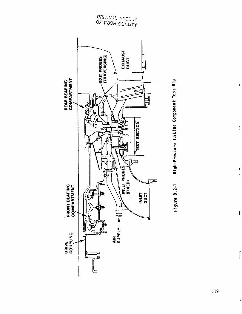
OF _OOR QUALi'_'y
L
zo
oe,--O_
+a
qJI--"
C
e-0a.
0(.3
C
=_l.-.-
_J
It-
.p=.
!
&.
119
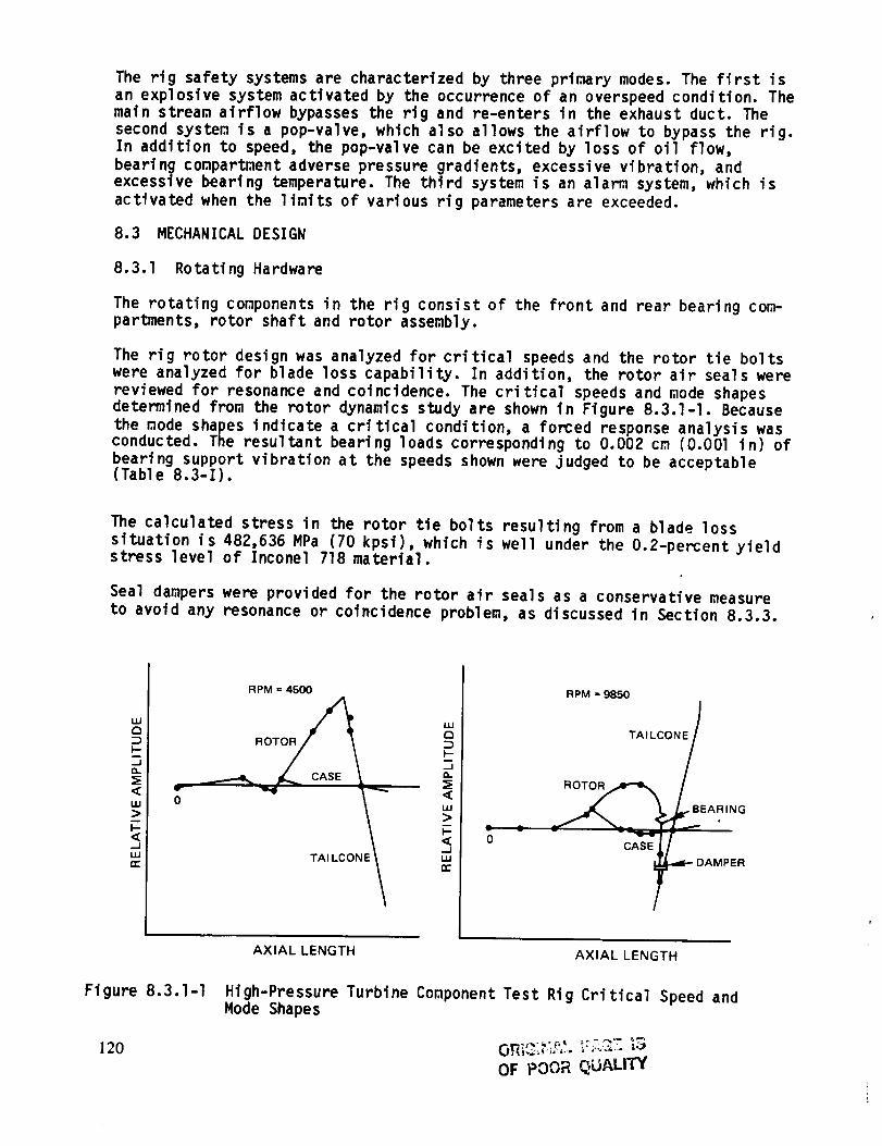
The rig safety systems are characterized by three primary modes. The first isan explosive system activated by the occurrence of an overspeed condition. Thematn stream airflow bypasses the rig and re-enters in the exhaust duct. Thesecond system is a pop-valve, which also allows the airflow to bypass the rig.In addition to speed, the pop-valve can be excited by loss of oil flow,bearing compartment adverse pressure gradients, excessive vibration, andexcessive bearing temperature. The third system is an alarm system, which isactivated when the limits of various rig parameters are exceeded.
8.3 MECHANICAL DESIGN
8.3.1 Rotating Hardware
The rotating components in the rig consist of the front and rear bearing com-partments, rotor shaft and rotor assembly.
The rig rotor design was analyzed for critical speeds and the rotor tie bolts
were analyzed for blade loss capability. In addition, the rotor air seals were
reviewed for resonance and coincidence. The critical speeds and mode shapesdetermined from the rotor dynamics study are shown in Figure 8.3.1-I. Because
the mode shapes indicate a critical condition, a forced response analysis wasconducted. The resultant bearing loads corresponding to 0.002 cm (0.001 in) of
bearing support vibration at the speeds shown were judged to be acceptable(Table 8.3-I).
The calculated stress in the rotor tie bolts resulting from a blade loss
situation is 482,636 MPa (70 kpsi), which is well under the O.2-percentyieldstress level of Inconel 718 material.
Seal dampers were provided for the rotor air seals as a conservative measure
to avoid any resonance or coincidence problem, as discussed in Section 8.3.3.
UJ
a
F-
a.
:E<LU>
<
UJn"
r
0
RPM = 4500
"'QRO _
-Ja.
_""'' TA I LC ONf n,-uJ"__I.,u
0
RPM = 9850
TAILCONE /
CASE f
DAMPER
Figure 8.3. I-I
120
AXIAL LENGTH AXIAL LENGTH
High-Pressure Turbine Component Test Rig Critical Speed andMode Shapes
OF POOR QUALITY
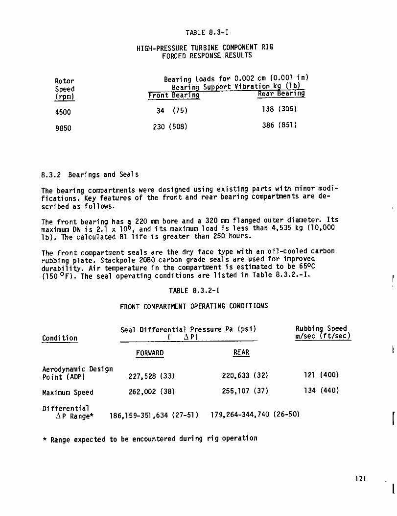
TABLE8.3-1
HIGH-PRESSURETURBINECOMPONENTRIGFORCEDRESPONSERESULTS
RotorSpeed
Bearing Loads for 0.002 cm (0.001 in)Bearin 9 Support Vibration k_ (Ib)
Front BearinB Rear Bea_rin_
4500 34 (75) 138 (306)
9850 230 (508) 386 (851)
8.3.2 Bearings and Seals
The bearing compartments were designed using existing parts with minor modi-
fications. Key features of the front and rear bearing compartments are de-scribed as follows.
The front bearing has a 220 mm bore and a 320 mm flanged outer diameter. Itsmaximum DN is 2.1 x 10⁶ , and its maximum load is less than 4,535 kg (lO,O00
Ib). The calculated Bl life is greater than 250 hours.
The front compartment seals are the dry face type with an oil-cooled carbonrubbing plate. Stackpole 2080 carbon grade seals are used for improved
durability. Air temperature in the compartment is estimated to be 65oc
(150°F). The seal operating conditions are listed in Table 8.3.Z.-I.
TABLE 8.3.2-1
FRONT COMPARTMENT OPERATING CONDITIONS
Condi tion
Aerodynamic DesignPoint (ADP)
Maximum Speed
Differential
/%P Range*
Seal Differential Pressure Pa (psi)( AP)
FORWARD REAR
Rubbing Speedm/sec (ft/sec)
227,528 (33)
262,002 (38)
220,633 (32)
255,107 (37)
IZl (400)
134 (440)
186,159-351,634 (27-51) 179,264-344,740 (26-50)
* Range expected to be encountered during rig operation
121
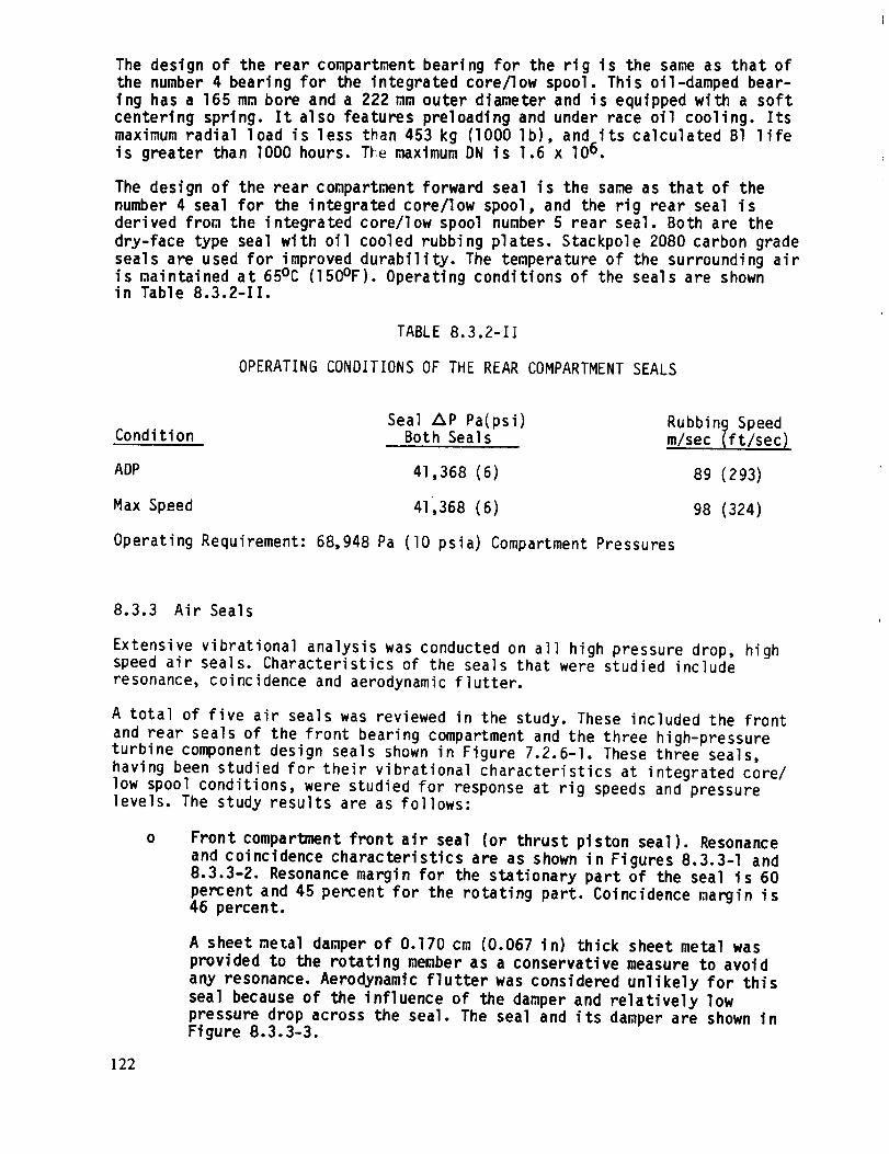
The design of the rear compartment bearing for the rig is the same as that ofthe number 4 bearing for the integrated core/low spool. This oil-damped bear-ing has a 165 mm bore and a 222 mm outer diameter and is equipped with a softcentering spring. It also features preloadtng and under race oil cooling. Itsmaximum radial load is less than 453 kg (1000 lb), and its calculated B1 lifeis greater than lO00 hours. The maximum DN is 1.6 x lO 6,
The design of the rear compartment forward seal is the same as that of the
number 4 seal for the integrated core/low spool, and the rig rear seal is
derived from the integrated core/low spool number 5 rear seal. Both are the
dry-face type seal with oil cooled rubbing plates. Stackpole 2080 carbon grade
seals are used for improved durability. The temperature of the surrounding airis maintained at 65°C (150°F). Operating conditions of the seals are shownin Table 8.3.2-II.
TABLE 8.3.2-II
OPERATING CONDITIONS OF THE REAR COMPARTMENT SEALS
Seal Z_P Pa(psi) Rubbing Speed
Condition Both Seals m/sec (ft/sec 1
ADP 41,368 (6) 89 (293)
Max Speed 41,368 (6) 98 (324)
Operating Requirement: 68,948 Pa (lO psia) Compartment Pressures
8.3.3 Air Seals
Extensive vibrational analysis was conducted on all high pressure drop, highspeed air seals. Characteristics of the seals that were studied include
resonance, coincidence and aerodynamic flutter.
A total of five air seals was reviewed in the study. These included the front
and rear seals of the front bearing compartment and the three high-pressureturbine component design seals shown in Figure 7.2.6-I. These three seals,
having been studied for their vibrational characteristics at integrated core/
low spool conditions, were studied for response at rig speeds and pressurelevels. The study results are as follows:
0 Front compartment front air seal (or thrust piston seal). Resonance
and coincidence characteristics are as shown in Figures 8.3.3-I and
8.3.3-2. Resonance margin for the stationary part of the seal is 60
percent and 45 percent for the rotating part. Coincidence margin is46 percent.
A sheet metal damper of 0.170 cm (0.067 in) thick sheet metal was
provided to the rotating member as a conservative measure to avoid
any resonance. Aerodynamic flutter was considered unlikely for this
seal because of the influence of the damper and relatively low
pressure drop across the seal. The seal and its damper are shown inFigure 8.3.3-3.
122
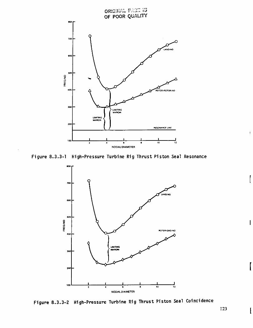
800 J
7O0
600m
SO0
¢3Z
,.=4O0
300 --
2OO
100
Figure 8.3.3-1
7O01 _
0
0
w.
lo0
Figure 8.3.3-2
OF POOR QUALITY
ROTOR/ROTOR/ND
LIMITING
MARGIN
LIMITING
MARGIN
RESONANCE LINE
I I I I I l2 4 6 8 10 12
NODAL DIAMETER
High-Pressure Turbine Rig Thrust Piston Seal
m
Resonance
ROTOR/GND/ND
I I I I I I2 4 6 8 10 12
NODAL DIAMETER
High-Pressure Turbtne Rig Thrust Ptston Seal Coincidence
123 J

ORIGlt_AL P_G_ _3
OF POOR QUALITY
DAMPER CUT INTO8 SEGMENTS
(AMS 5504)
Figure 8.3.3-3 Front Compartment Front Airseal (Thrust Piston Seal)
O Front compartment rear airseal. This seal's function is to act as abackup seal in the event of a malfunction of the carbon seal. A one-knife edge design was selected as best suited for this purpose in theunlikely event of a carbon seal failure.
Resonance and coincidence margins for this seal were found to be in-adequate, Figures 8.3.3-4 and 8.3.3-5 indicate no margin near thethree nodal diameter frequency mode for both resonance and coinci-dence. A damping feature was provided for this seal to avoid reson-ance or coincidence. The damper is constructed of 0.160 cm (0.063 in)thick sheet metal and is provided for both rotating and nonrotatingmembers. The configuration of the seal with dampers is shown inFigure 8.3.3-6.
The addition of dampers to this seal, along with its single knifeedge design, makes it a low risk for aerodynamic flutter.
High-pressure compressor discharge seal. Resonance margin for this
seal, as shown in Figure 8.3.3-7, is 83 percent for the rotor and 68
percent for the stationary member. Coincidence margin is II percent,as shown in Figure 8.3.3-8. Flutter stability for this seal was
analyzed for the integrated core/low spool application (Section
7.2.6.2) and found to be acceptable. The seal is therefore adequate
for the rig application because of the same pressure drops. Sheet
metal dampers 0.I09 cm (0.043 in) thick were provided for the
stationary member as a precautionary raeasure to provide additional
safety margin. The seal configuration with dampers is shown in Figure8.3.3-9.
124

1800
1400 _
120C
I00_ m
C3Z
E
4OO
2OO
Fi gure 8.3.3-4
OR,,=,,]_L P_.C :E
OF POGR QUALITY
LAND/NO
ROTOR/ROTOR/ND
NO
RESONANCE LINE
I I I l I I2 4 6 B 10 12
NODAL DIAMETER
High-Pressure Turbine Rtg Front Bearing Rear Seal Resonance
16OO
14OO
1200
O
zo,.=
1OOO
OOO
60O
Figure 8.3.3-5
COINCI
I I I I I I2 4 6 8 tO 12
NODAL DIAMETER
High-Pressure Turbine Rig Front Bearing Rear Seal Coi nci dence
125

OF pO0_ ,Q_"_'_ : _I
ROTATING DAMPER SLOTTEDINTO 8 FINGERS
(AMS 5504)
NON-ROTATING DAMPER
SLOTTED INTO 36 FINGERS
(AMS 5504)
Figure 8.3.3-6 Front Compartment Rear Airseal
24OO
14OO
OZ
8OO_
4OO
ROTOR/ROTOR/NO
I I I I I I2 4 6 8 tO 12
NODAL DIAMETER
Figure 8.3.3-7 High-Pressure Turbtne R19 High-Pressure Compressor DischargeSeal Resonance
126
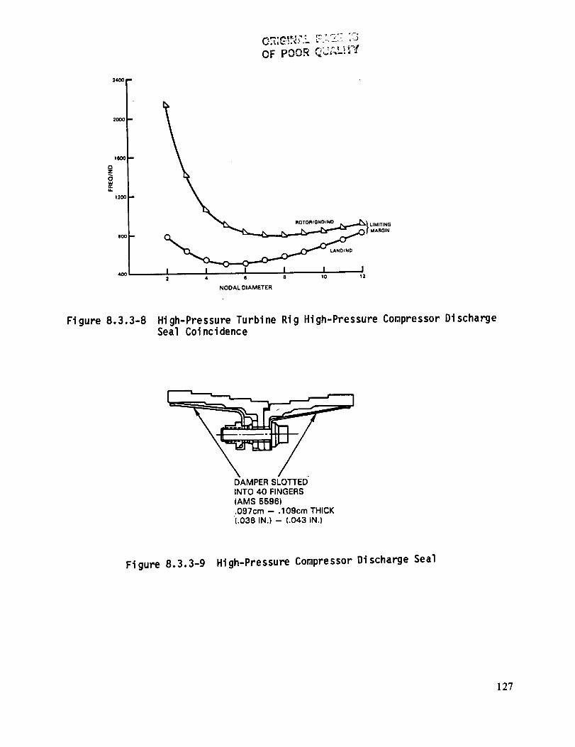
2400
2000 --
I000 m
0Z
..=1200 --
8O0
4OO
OF POOR QU_-_.L.q"I
LIMITING
MARGIN
I I I I I I2 4 6 8 10 12
NODAL DIAMETER
Figure 8.3.3-8 High-Pressure Turbine Rig High-Pressure Compressor DischargeSeal Coincidence
DAMPERSLOTTEDINTO 40 FINGERS(AMS 5596)•097cm - .109cm THICK(.038 IN.) -- (.043 IN.)
Figure 8.3.3-9 High-Pressure Compressor Discharge Seal
127
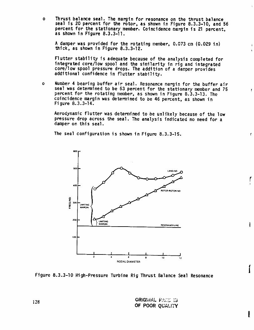
0 Thrust balance seal. The margin for resonance on the thrust balancesea] is 20 percent for the rotor, as shown in Figure 8.3.3-]0, and 56percent for the stationary member. Coincidence margin is 21 percent,as shown in Figure 8.3.3-11.
A damper was provided for the rotating member, 0.073 cm (0.029 in)thick, as shown in Figure 8.3.3-]2.
Flutter stability is adequate because of the analysis completed for
integrated core/low spool and the similarity in rig and integratedcore/low spool pressure drops. The addition of a damper provides
additional confidence in flutter stability.
Number 4 bearing buffer air seal. Resonance margin for the buffer airseal was determined to be 53 percent for the stationary member and 75
percent for the rotating member, as shown in Figure 8.3.3-13. The
coincidence margin was detemined to be 46 percent, as shown inFigure 8.3.3-14.
Aerodynamic flutter was detemined to be unlikely because of the low
pressure drop across the seal. The analysis indicated no need for a
damper on this seal.
The seal configuration is shown in Figure 8.3.3-15.
6OO
SOO
40O
Z
E
2O0
3MITING
dARGIN
MARGIN RESONANCE LINE
I I I I I I2 4 8 8 10 12
NODAL DIAMETER
Figure 8.3.3-10 High-Pressure Turbine Rig Thrust Balance Seal Resonance
128 ORIGh'L_.L _':_L'_ '_"
OF POOR QUAL;,Y
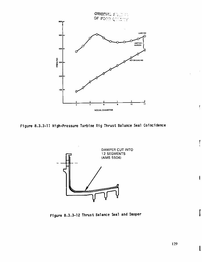
IK)Om
400 _,,
m
m
0Z
2OO
IO0
OF p£_"_.!_ _..............
I I I I I l2 4 6 8 10 12
NODAL DIAMETER
Figure 8.3.3-11 High-Pressure Turbine Rig Thrust Balance Seal Coincidence
DAMPER CUT INTO
12 SEGMENTS)
Ftgure 8.3.3-12 Thrust Balance Seal and Damper
129
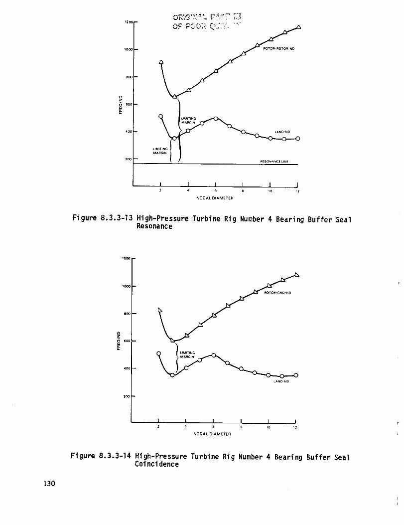
1200 --
1000
800 --
400
Z
200
,,_ _ i f,_.'_'_ _ _ I_,_, :_ ._ _'_
_" _,_,,_ _..-'__., ,
ROTOR_ROTOR_ND
RESONANCELINE
I I I I I I2 4 6 8 10 12
NODAL DIAMETER
Figure 8.3.3-13 High-Pressure Turbine Rig Number 4 Bearing Buffer SealResonance
1200
1000
800 --
QZ
O 600 --
LIMITtNG
MARGIN
LANDIND
I I2 4
I I I I6 8 10 12
NODAL DIAMETER
Figure 8.3.3-14 High-Pressure Turbine Rig Number 4 Bearing Buffer SealCoYnci dence
130
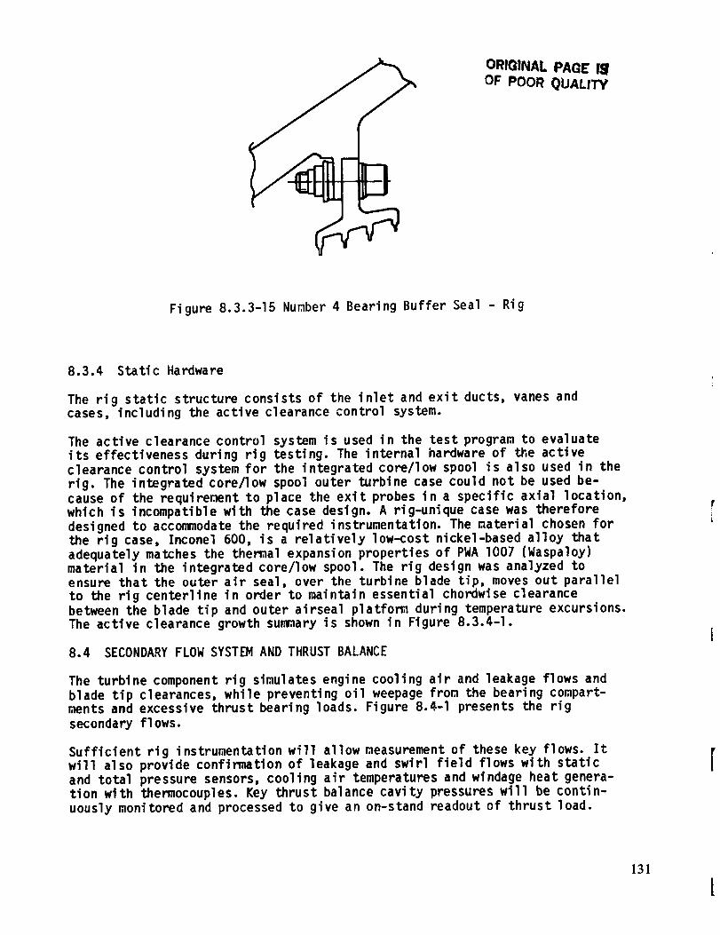
ORIQINAL PAGE 14OF POOR QUALITY
Figure 8.3.3-15 Number 4 Bearing Buffer Seal - Rig
8.3.4 Static Hardware
The rig static structure consists of the inlet and exit ducts, vanes andcases, including the active clearance control system.
The active clearance control system is used in the test program to evaluateits effectiveness during rig testing. The internal hardware of the active
clearance control system for the integrated core/low spool is also used in the
rig. The integrated core/low spool outer turbine case could not be used be-
cause of the requirement to place the exit probes in a specific axial location,
which is incompatible with the case design. A rig-unique case was therefore
designed to accommodate the required instrumentation. The material chosen for
the rig case, Inconel 600, is a relatively low-cost nickel-based alloy that
adequately matches the thermal expansion properties of PWA I007 (Waspaloy)
material in the integrated core/low spool. The rig design was analyzed toensure that the outer air seal, over the turbine blade tip, moves out parallel
to the rig centerline in order to maintain essential chordwise clearance
between the blade tip and outer airseal platfom during temperature excursions.
The active clearance growth summary is shown in Figure 8.3.4-I.
8.4 SECONDARY FLOW SYSTEM AND THRUST BALANCE
The turbine component rig simulates engine cooling air and leakage flows and
blade tip clearances, while preventing oil weepage from the bearing compart-ments and excessive thrust bearing loads. Figure 8.4-I presents the rig
secondary flows.
Sufficient rig instrumentation will allow measurement of these key flows. It
will also provide confirmation of leakage and swirl field flows with static
and total pressure sensors, cooling air temperatures and windage heat genera-tion with thermocouples. Key thrust balance cavity pressures will be contin-
uously monitored and processed to give an on-stand readout of thrust load.
131
[
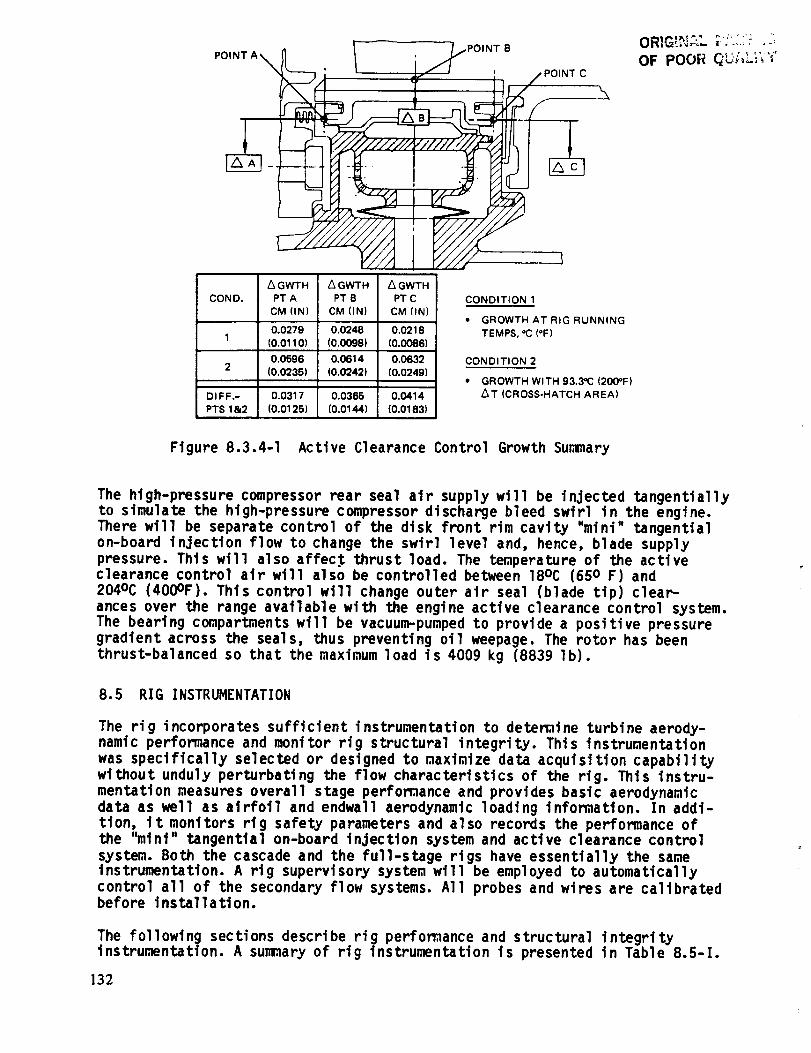
POINT A _IPOINT B
,;" ' __ ' __ POINTC
A GWTH _ GWTH L_ GWTH
COND, PT A PT B PT C
CM (IN) CM (IN) CM (IN)
0,0279 0,0248 0,02181 (0.0110) (0.0098) (0,0086)
0.0596 0,0614 0.0632
2 (0,0235) (0.0242) (0,0249)
DIFF,- 0,0317 0,0365 0,0414
PTS 1&2 (0,0125) (0.0144) (0,0163)
CONDITION 1
* GROWTH AT RIG RUNNING
TEMPS, °C (=F)
CONDITION 2
* GROWTH WITH 93,3"C (200°F)
AT (CROSS-HATCH AREA)
ORIG'_,'.;L "+ .... -="..,+: : .:
OF POOR " :+'...... ++'
Figure 8.3.4-1 Active Clearance Control Growth Summary
The high-pressure compressor rear seal air supply will be injected tangentially
to simulate the high-pressure compressor discharge bleed swirl in the engine.
There will be separate control of the disk front rim cavity "mini" tangential
on-board injection flow to change the swirl level and, hence, blade supply
pressure. This will also affec.t thrust load. The temperature of the activeclearance control air will also be controlled between 18oc (650 F) and
204°C (400OF). This control will change outer air seal (blade tip) clear-
ances over the range available with the engine active clearance control system.
The bearing compartments will be vacuum-pumped to provide a positive pressure
gradient across the seals, thus preventing oil weepage. The rotor has been
thrust-balanced so that the maximum load is 4009 kg (8839 Ib).
8.5 RIG INSTRUMENTATION
The rig incorporates sufficient instrumentation to detemine turbine aerody-
namic performance and monitor rig structural integrity. This instrumentation
was specifically selected or designed to maximize data acquisition capability
without unduly perturbating the flow characteristics of the rig. This instru-
mentation measures overall stage performance and provides basic aerodynamicdata as well as airfoil and endwall aerodynamic loading information. In addi-
tion, it monitors rig safety parameters and also records the performance ofthe "mini" tangential on-board injection system and active clearance control
system. Both the cascade and the full-stage rigs have essentially the sameinstrumentation. A rig supervisory system will be employed to automatically
control all of the secondary flow systems. All probes and wires are calibratedbefore instal Iati on.
The following sections describe rig perfomance and structural integrityinstrumentation. A summary of rig instrumentation is presented in Table 8.5-I.
132
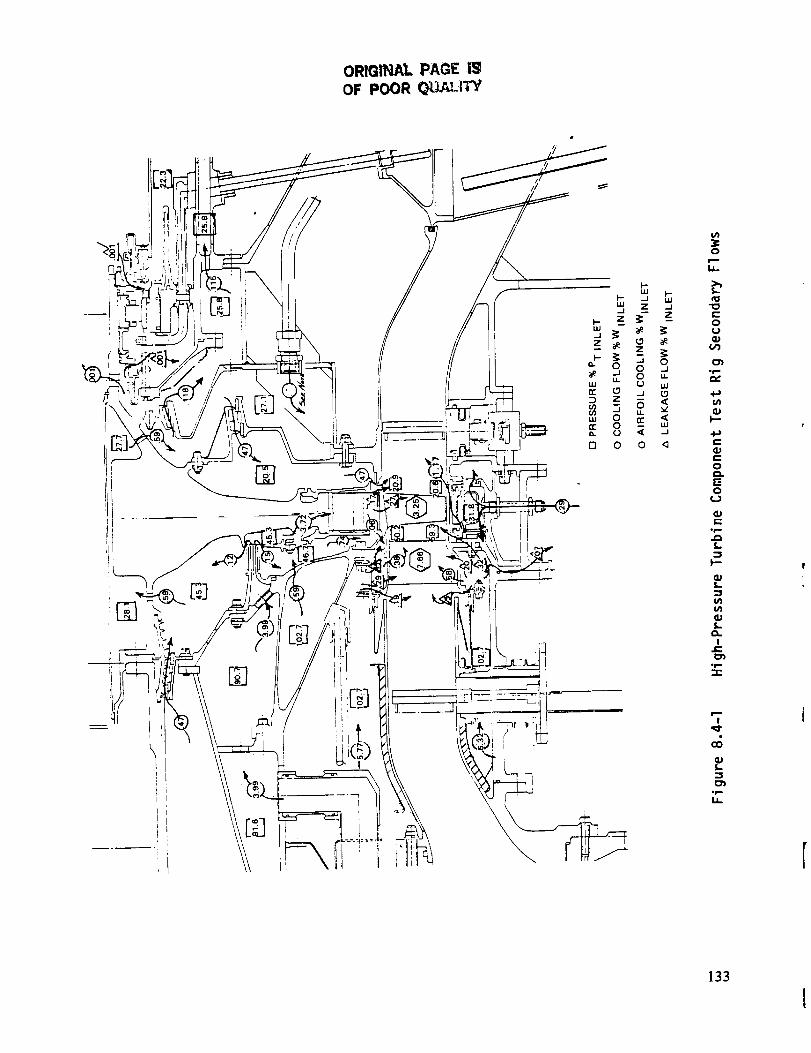
ORIGllCa,L PAGE I_OF POOR Q_JAI.tTV
iin i
:¢0
I.I-
b_0
0
0
._
4_
t-Oc-
OCkr:-0
I.
t/1
0t-O.
Ie-
t_
i,
133
l

Rig Super-
visory Control
Inlet
Vane Surface
& Shrouds
Blade Outer Air
Seal (OAS) and
Active Clearance
Control (ACC)
System
Exi t
Vane Cooling
Tangential On-
Board Injector
(TOBI)
Disk Bore
Cooling
Exit
Cavities
Bearing Com-96rtments
Totals
Laser Proximity
Vibrat ion
Speed
Air Angle
TT
8O
48
PT
TT
PS
TAIR
Tmetal
4
10
3
4
TABLE 8.5-1
INSTRUMENTATION SUMMARY
PT TAir Tmetal
2 i0 -
PS Miscellaneous
16
40 24
153
22 28 22 Laser Prox.
48
16
22
24
16
22
4 Air Angle
12 64 64
8 8
102
130
371
152
52
i0 24 22 I0 Vibration
3 speed
134
8.5.1 Perfomance Instrumentation
Perfomance instrumentation measures inlet and exit flow, and blade tip
clearance.
Inlet Instrumentation. Inlet instrumentation consists of 4 total pres-
sure rakes, each with 10 sensors. In addition, there are 12 static pres-
sure taps located on both the inner and outer flowpath. The inlet rakes
are properly located circumferentially to prevent any rotor excitation.
Exit Instrumentation. Exit instrumentation consists of 4 total pressure
rakes and 4 total temperature rakes each with 12 sensors. In addition,
there are 12 static pressure taps located in both the inner and outer
flowpath. The rakes are located on a ring that can be traversed circum-
ferentially approximately 30 degrees. These rakes are positioned 90
degrees apart. Coupled with the pressure and temperature rakes, there are4 air angle probes located at the exit plane. These probes are wedge
shaped and have the ability to traverse radially as well as circumferen-
tially. They are used to measure two static pressures and a total
pressure, and are also used to calculate exit air angle.
Blade Tip Clearance Measurement. Four equally spaced laser probes willbe used to measure and monitor the blade tip clearance. These probes will
be attached to the blade outer air seal shoes, extend through the outer
cases, and sealed by means of piston rings. Temperature variations in theflow to the active clearance control system will provide tip clearance
changes. Probe measurements will then be used to determine any changes in
performance resulting from variations in tip clearance.
Compartment Air Temperature. Air temperature measurements taken invarious compartments, especially those conducting secondary air flow,will be useful in calculating performance parameters.
8.5.2 Structural Integrity Instrumentation
This instrumentation verifies design assumptions and measures static tempera-
tures, pressures, and bearing temperatures. Probe strain gages and accelero-meters are also used.
Static Pressure. Two turbine vanes will be instrumented on the airfoil
surface at three spanwise locations. Seventeen airfoil static pressure
taps will be positioned at each location, 10 on the suction surface and 7on the pressure surface. Endwall static pressure taps will be placed at
both the inner and outer flowpath platforms. The number of these used
will depend on available platform area. Static pressure taps will also be
located throughout the rig in order to determine cooling and leakageflows.
Static Temperature. One vane will be instrumented in the airfoil sectionto determine the effectiveness of the cooling scheme. In addition,
instrumentation will be located on the active clearance control system to
verify its operation. All cooling flow systems will be instrumented to
monitor and maintain control of coolant flow temperatures.
135 [

Bearing Temperatures. Thermocouples will be located in the bearingCompartments to ensure proper bearing and seal operating temperatures.This instrumentation will be monitored throughout the test program.
Probe Strain Gages. The fixed inlet rakes will be strain gaged at theroot of _e rake to detect probe vibratory modes that might exist at testconditions.
Accelerometer. Both horizontal and vertical accelerometers will be
located on the front and rear bearing supports. These wtll be monitoredthroughout the test program.
8.6 FACILITY/RIG ADAPTATION
The facility for testing the high-pressure turbine component rig will provide
an open-loop air supply system. Two natural gas burners heat the primary air
to approximately 426oc (800OF). The secondary air, supplied by the main-
stream air upstream of the combustor, is delivered to the rig at approximately
65°C (150°F), thus maintaining the proper main air temperature and cooling
air temperature ratio. Power generated by the turbine is absorbed through two
lO,O00 horsepower dynamometers. The rig is connected to the power absorption
system through a coupling and gearbox. There are provisions for seven indepen-
dent secondary cooling air systems. Flow for both the primary and secondaryair systems is metered through critical flow venturies. An automated data
secondary system will be used to process data, and a rig supervisory systemwill be employed to control all secondary flows.
136
SECTION9.0CONCLUDINGREMARKS
The high-pressure turbine design in the Energy Efficient Engine represents aconsiderable advancement in turbine technology. The design capitalizes on the
inherent economic and weight advantages offered with a single stage system by
applying technology advancements in the areas of structures, ae,-odynamics and
materials. On the basis of results acquired from design analyses and, more im-
portantly, supporting experimental test programs, turbine performance and dur-
ability goals are achieveable. The predicted efficiency of 88.8 percent for
the flight propulsion system exceeds the goal of 88.2 percent. Durability ex-
pectations are commensurate with commercial service operation.
Overall, the technology evolved through the turbine design processes and
eventual demonstration during the integrated core/low spool test program will
have wide application. Much of this technology, particularly high temperature
capability materials, is applicable to any gas-turbine engine of the next gen-eration, including advanced derivative models of current commercial engines.
137

APPENDIX A
ENERGY EFFICIENT ENGINE HIGH PRESSURE TURBINE
COMPONENT VANE AND BLADE AIRFOIL COORDINATES
PRECEDING PAGE BLANK NOT RL_|EO
139
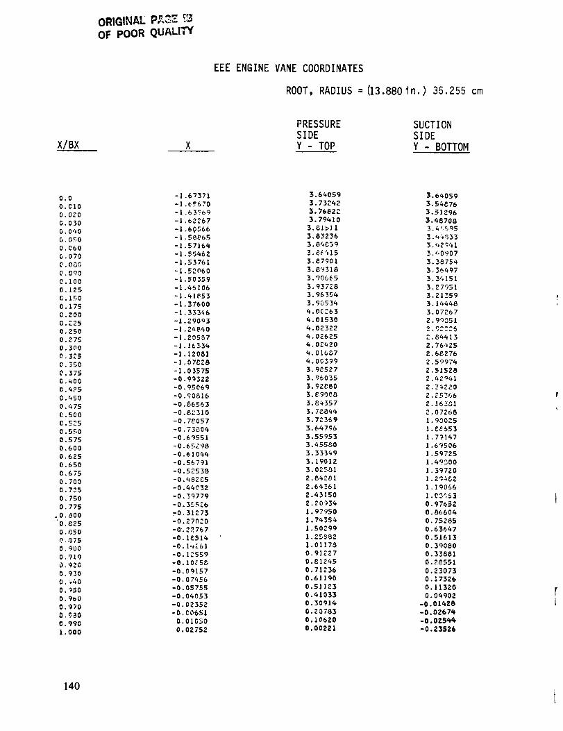
ORIGINAL P,_ [3OF POOR QUALITY
EEE ENGINE VANE COORDINATES
ROOT, RADIUS =(13.880in.) 35.255 cm
X/BX
PRESSURE SUCTION
SIDE SIDE
Y - TOP Y - BOTTOM
0.0
O.CIO
0.020
O. 030
O. 0"+0
G. 0_0
0.060
0.070
O. 0_.,_
O.OqO
0.100
0.125
0.150
0.175
0.200
0.225
0.250
0. 275
O. 300
O. 325
O. 350
0.375
0._,00
0.6?5
0.450
0.4750.500
0.5?.50.550
0.5750.600
0.625
0.650
0.675
0.700
0.725
0. 750
O. 775
.0.800
'0,825
0.850
0..3750.900
0.910
0.920
0.9300. :_,_0
O. 950
O. 900
0.970
0.980
0.990
I .000
-1.67371
-1.E_670
-1.63_69
-1.63267
-I.60566
-|.58865
-1.57164
-I .55662
-1.53761
-! _2060
-1 50359
-1 _5106
-1 61P53
-1 37600
-1 333q6
-1 29003
-l 24840
-1 20557
-1.16336
-1.12081
-1.07_28
-I.03575
-0.99322
-0.95069
-0.90816
-0.86563
-0.8_310
-0.78057
-0.73806
-0.69551
-0.65Z98
-0.610_
-0.56791
-0.52538
-0._8_5
-0._032
-0.39779
-0.35526
-0.31273
-0.27_20
-0.22767
-0 1G51_
-0 1,*_61
-0 12559
-0 10_5_
-0 09157
-0 07_56
-0 05755
-0.0_053
-0.02352
-0.00651
0.01050
0.02752
3.66059
3.73262
5.76822
3.79_10
3.51>11
3.83236
3.8_39
3._6315
3.87901
3.89318
3.90665
3.937_8
3.96354
3.9053_
6.0G_636.01530
6.02322_.02625
6.02620
6.01G_7
6.00399
3.9_527
3.95035
3.92880
3._008
3.8_357
3.788_6
3.7_369
3.66796
5.55953
3._55_0
3.333_9
3.19012
3.0_F81
2.8_281
2.6_61
2.43150
2,_0936
1.97950
1.76356
1.502991.25882
1.0117_
0.91227
0.812_5
0.71236
0.61190
0.51123
0.61033
0.3091_
0.Z0783
0.10620
0.00221
3.o_059
3.56876
3.51296
3._8706
3._(595
3._$33
3._2_13._0907
3.3875_
3 36_97
3 3_151
3 27951
3 21_59
3 166_8
3 07267
2 99351
2.8_13
2.76625
2.68276
2.59976
2.51528
2._2o61
2._220
2.25_66
2.16_1
2.07268
1.90025
1.E8653
1.79167
1.6_506
1.59725
1._9600
1.39720
1.29_02
1.19066
!.03_$1
0.97652
0.86606
0,75285
0.63667
0.51613
0.39080
0.33881
0.28551
0.23073
0.17326
0.11320
0.06902
-0.01628
-0.02676-0.0256_
-0.23526
140
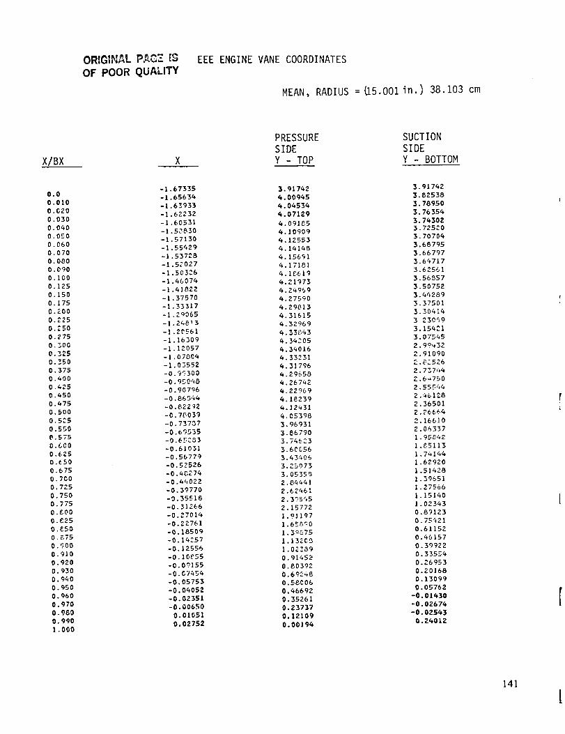
ORIGINAL PAG_ [,_
OF POOR QUALITYEEE ENGINE VANE COORDINATES
MEAN, RADIUS : _5.001in.) 38.103 cm
X/BX
0.0
O.OIO
O.G20
0.030
0.O4O
O.O.rO
0.060
O. 070
O. 080
O. 090
O.IO0
O. 125
0.150
O. 175
0.200
0.225
O. _.50
O. 275
0._o0
0.325
0.350
0.375
0.400
0.425
0.450
0.475
0.500
0.5£5
0.550
O. 575
0.600
0.625
0._50
0.675
0. 700
O. 77.S
O. 750
O 775
0 gO0
O _25
0 t_,50
O g75
O ._O0
0.910
0.920
0.930
0.940
0.950
O. 960
0.970
0.960
0.990
I .000
-1,67335
-],65634
-1.63933
-].62232
-1.60531
-1.59830
-1.57130
-1.55429
-1.53728
-1.5£027
-1.50326
-1.46074
-1.418Z2
-1.37570
-1.33317
-I,24065
-1.24813
-1.2_561
-1.16309
-1.12057
-1.07604
-1.03552
-0.9_300
-0.95048
-0.90796
-0.86544
-O 822_2
-O 76039
-0 73737
-0 6_535
-0 6_C33
-O 61031
-0 56779
-0 52526-0 4C274
-O 44022-O 39770
-0 35516-0 3]366
-O 27014-0.2276]
-0.18509-0.14257
-0.12556-0.10_55
-0.07155-0.07454
-0. 05753
-0.04052
-0.02351
-0.00650
0.0105l
0.02752
PRESSURESIDEY - TOP
3.91742
6.00945
4,04534
4.07129
4.09185
4.10909
4,12553
4.1414B
4.15691
4.17181
4.18619
4.21973
4.24969
4.27590
4.29813
4,31615
4.3_969
4.33_3
4.36205
4.34016
4. 33231
4.31796
4.29650
4.26742
4.22769
4.18239
4.12_3!
4.05396
3.96931
3.86790
3.74623
3.60056
3.43406
3.25073
3.05355
2.84441
2.62461
2.395_5
2.15772
1.9]197
1.65Ca0
1.3_75
|.13205
1.02_39
0.91452
0.80392
0.69248
0.58006
0.46692
0.35261
0.23737
0.12109
0.00194
SUCTIONSIDEY - BOTTOM
3.91742
3.82538
3. 78950
3.76354
3. 743023.725C0
3.70704
3.68795
3.66797
3.64717
3.62561
3.56857
3.50752
3.44289
3.37501
3.30414
3230_9
3,15421
3,07545
2.99_32
2.91090
2.82526
2.737_4
Z.6_750
2.55544
2.461_8
2.36501
2.76664
3. 16610
2.06337
1.95_42
1,_5113
1.74144
1.62920
1,514281.39651
1.275661.15140
1.023430.89123
0.75_210.61152
0.46157
0.39922
0.33554
0.26953
0.Z01680.13099
0.05762
-0.01430
-0.02674
-0.02543
0.24012
141
!
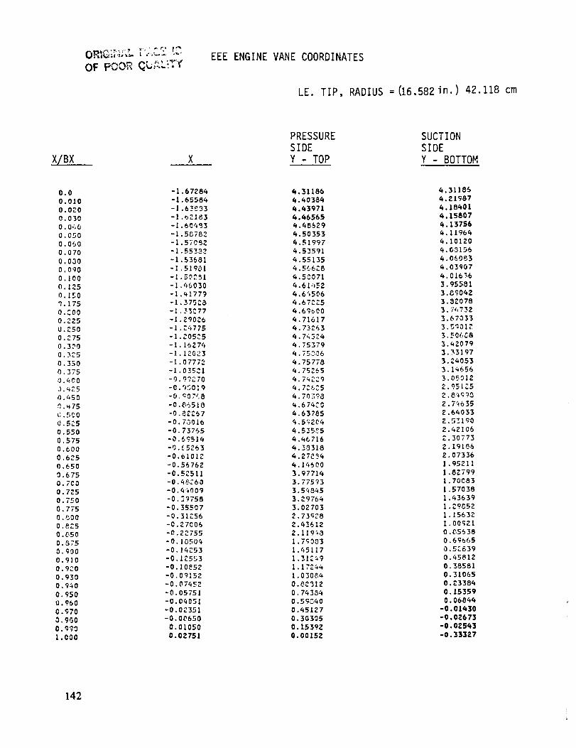
OF PCOR Q : +
EEE ENGINE VANE COORDINATES
LE. TIP, RADIUS = (16.582 in.) 42. 118 cm
X/BX
0.0
0,010
0.020
0.030
0.0,'+ 0
O. 050
0.0S0
0.070
0,030
0.090
0.100
O. 125
0.150q.175
O.C.O0
0.225
U._50
O. 2750.300
0 ._5
0.350
0,375
0.400
,) .025
0. L,50
0._75
l). 5_ 0
_,5t.5
0.550
0.575
0.600
0.625
0,650
0.6750.7C0
O. 725
O. 750
0. 775
0.800
0.8Z5
0 .C,50
O. $750.900
0.910
0.9_0
0.930
0.940
O. 950
0.960
0.970
O.9GO
O. 9';'0
1.000
-1.67286
-1.65584
-1.02183
-1.60483
-1.5C782
-I.5}OSZ
-1.55337
-1.53681
-1.51901
-1.50251
-I.96030
-1.41779
-1.375C3
-1._3_77
-1.290Z6
-1.Z:,775
-1.205_5
-1. 1627_
-1.120_3
-I 07772
-I 03521
-0 9_70
-0 950:9
-0 c07C8
-0 86510
-0 8_C57
-0.7001b
-0,73765
-0.6751_
-9,G5263
-0.61012
-0.56762
-0.5_511
-0.46_60
-0.4_009
-0.3_75B
-0.35507
-0.31_56
-0.27006
-0.22755
-0.10504
-0.14253
-0.1_553
-0.I0_52
-0.09152
-0.07452
-0.05751
-0.04051
-0.02351
-0.00650
0.01050
0.0Z751
PRESSURE
SIDE
Y - TOP
4.31186
4.40384
4.;3971
6.66565
4 ._8629
6.50353
_.51997
4.53591
_.55135
_.5_071
6.61452
6.6_5_6
_.67_5
_.69_00
_.71617
_.73263
4.79524
4.75379
4.75_06
4.75778
4.752_56.7_Z9
4.7_6C5
4.70398
4.674C0
_.63785
_.5_ZO_
6.535_5
_._6716
4.3_318
3.9771_3.775_3
3.5q_453._976_
3.027032.73928
2.q36122.119_3
1.7_0031.45117
1.312491.17Z#4
1.030_
0.0_12
0.74354
0.59040
0.45127
0.30305
0.1539Z
0.00152
SUCTION
SIDE
Y - BOTTOM
_.31185
_,Z1987
6.18401
_.15807
_.13756
4.11964
4.101_0
q.G_I56
_.O_OB3
4.03907
_.01636
3.95381
3.G_042
3.3_078
3.7_732
3.67033
3.5_012
3.50688
3.42079
3.33197
3._053
3.14656
3.05012
2.951Z5
2.8_9_3
2.7_635
_.6_033
_.5_l_0
2.42106
Z.30773
Z.191_6
2.07336
1.95211
1,8Z799
1.70083
1.57038
1.43639
1.2905_
1.15632
1.00_I
0._5638
0.69_65
0.5_639
0.45812
0.38551
0.31065
0.23384
0.15359
0.0684_
-0.01430
-0.02673
-0.0Z5_3
-0.333_7
142

QL-AL_TYEEE ENGINE BLADE COORDINATES
ROOT, RADIUS =(13.678in.) 34.742 cm
X/BX X
SUCTION PRESSURESIDE SIDEY - TOP Y - BOTTOM
0.0
0.010
O. 0:-0
0.030
0.0q0
0.050
0.060
C. 070
0.080
O.CgO
0.100
0.125
0.150
0. 173
C,_00
o .225
O._SO
0.275
0.300
0.325
0. 350
0.375
0.400
O. 4._5
0.450
0.475
0.5C0
0.5Z5
0.550
0.57_
0.500
0.625
0.650
0.575
0.700
0.725
0. 750
0. 775
0.800
0.525
0 ¢50
0 675
Q <;00
0 910
0 9."0
0 930
0 940
0 950
0 960
0 970
0.960
C.9901.000
0.00006
0.01352
0,02695
O.0_oq5
0.05391
0.06737
O.OGOS4
0.09430
0.10776
0.12123
0.13q69
0.16B35
0._$2CI
0.2_067
0.26933
0.30_99
0.33655
0.37030
0,40396
0.43762
0 ._7128
0.504_
0.53950
0.57226
0.60_92
0.6355B
0.67323
0.70689
0.74055
0.77431
0._0707
0.64153
0.87519
0.90385
0.94251
0.97617
1.04348
1.07714
l.llC_O
l.lq4q6
1.17012
1.2117_
1.72524
1.23_70
1.25317
1.26563
1.27909
1.29256
I._0602
1.31943
_.332_5
1.34641
I.o83971.13073
l.lC03_
1.21SC6
1.2_638
1.2!018
1.31302
1.33_95
1.35601
1.405_3
!.4%c57
1.5Z554
1.55756
1.576t5
1.6!003
1._3203
1.64_75
1,663'_0
1.67_q6
1.68131
1.68_35
!.6933g
1.67_16
1.66035
1.63331
1.63303
1.60610
1.5713_
1.52772
1.47161
i.39C37
1,30322
1.21310
1.01i40
0.90717
O.BOIOI
0.6_305
0.50330
0.47106
0,42674
0.35123
0.33535
0.25949
0.24275
0.1957_
0.14835
0.1002_
0.05151
-0.00199
1,05397
1.04116
1.02650
1.01756
1.01216
1.00955
1.00941
1.01175
1.01680
1.02512
1.03475
1.055!5
1.07394
1.0_31
1.0_9q3
1.10747
_._5_
1.11470
I.i1405
I,!I069
l.lOq_4
1.09392
I C70¢5
I 05409
1 03491
1Cl3!l
0 _L363
0 9_143
0 93151
0.69573
0.66303
0.7_241
0.737_4
0.650360.6%_0
0.57_5
0.51_4
0.45397
0.333q5
0.30721
0._2_;34
0.]89!8
0.15270
O.IIA_6
0.07499
0.03371
-0.00955
-0.0_621
-0.0_9Q4
-0.02561
-0.00199
143

OF FOOR QULLITY
EEE ENGINE BLADE COORDINATES
MEAN, RADIUS =I14.913in.) 37.879 cm
X/BX X
SUCTION
SIDEY - TOP
PRESSURE
SIDE
Y - BOTTOM
0.0
0.010
0.020
0.030
O. Ot+O
0.050
0.070
0.000
0.0'?0
0.I00
0.1."5
O. 150
0.175
0.200
0.;'25
0.250
O. 275
0.300
0.3,'5
0.350
O. 375
0.400
0 .(_25
o. _,50
O.q7E,
o. 5f: 0
0.52.5
0.550
0.5750.6t!0
0.62.5
0.6"_0
0.675
0.7(_0
0.725
0.750
0.T;5
0.800
0.225
o.sr_,o
0.875
0.900
0.910
O. 9:'0
0.930
0.940
0. 950
0.950
0.970
O. 930
0.990
1.000
0.11588
0.12748
0.13907
0.150_6
0.16225
0.17724
0.18543
0.19703
0.203_2
0.22021
0 231_0
0 :5978
0 2_976
0 31874
0 3_772
0 37670
0 40568
0 43q{,G
0 4679%
0 49261
0 52159
0 55057
0 57955
0 _0353
0 63751
0 666_9
0 695:;7
0 7_/+45
0 753_3
0 7_4!
0 31139
0 6_037
0 86935
0 89_32
0 92730
0 95628
0 93525
1.01424
1.0#322
1.03"220
1.10118
1.13016
1.1591G
1.17073
1.1_232
1.19391
1.20550
1,21710
1.22669
1.24028
1._5187
1.263_6
1.27505
1.371011.41_88
1.44625
1.q7_ll
1.49979
1.52358
1.5q5701.56630
1.5_3531.60151
1.62332
1.65774
1.6_%27
1.71555
1.73717
1.75q29
1.76721
1.77526
1.72_'_I
1.7_!77
1.77_51
1.77129
1.75955
1.7q3_2
1.72222
1.695_9
1.662q3
1.62107
1.57205
1.50979
1._:3295
1.3502_
1.26463
1.17735
1.05S67
0.932_0
0.81(,39
0.72¢433
0.65081
0.5_31
0.4_235
O._q6G3
0.30793
0.2692_
0.23035
0.19!_7
0.15220
0.11255
0.07297
0.03329
-0.00666
-0.05190
1.37101
1.33092
1.31674
1.30765
1.30102
1.29729
1.29611
I._9615
1.29501
1.30183
1.30797
1.32937
1 30718
1 35_5
1 36_53
I _{554
! _6:'23
1 25399
1 341f6
1 32603
I _0652
1 26_/,2
1 ZE_95
1 22732
i 19"_5
I. 15_;'_%
1.11957
I .07777
1.03_15
0.9S176
0._5_62
0.B8277
0.827_7
0.76907
0.70328
0.6q485
_._7272
0.51007
0.q_77
0.36_76
0.23_10
0.20371
0.12659
0.00297
0.058C5
0.02427
-0.01061
-0.046_6
-0.07201
-0.078_8
-0.07909
-0.07_35
-0.05190
144
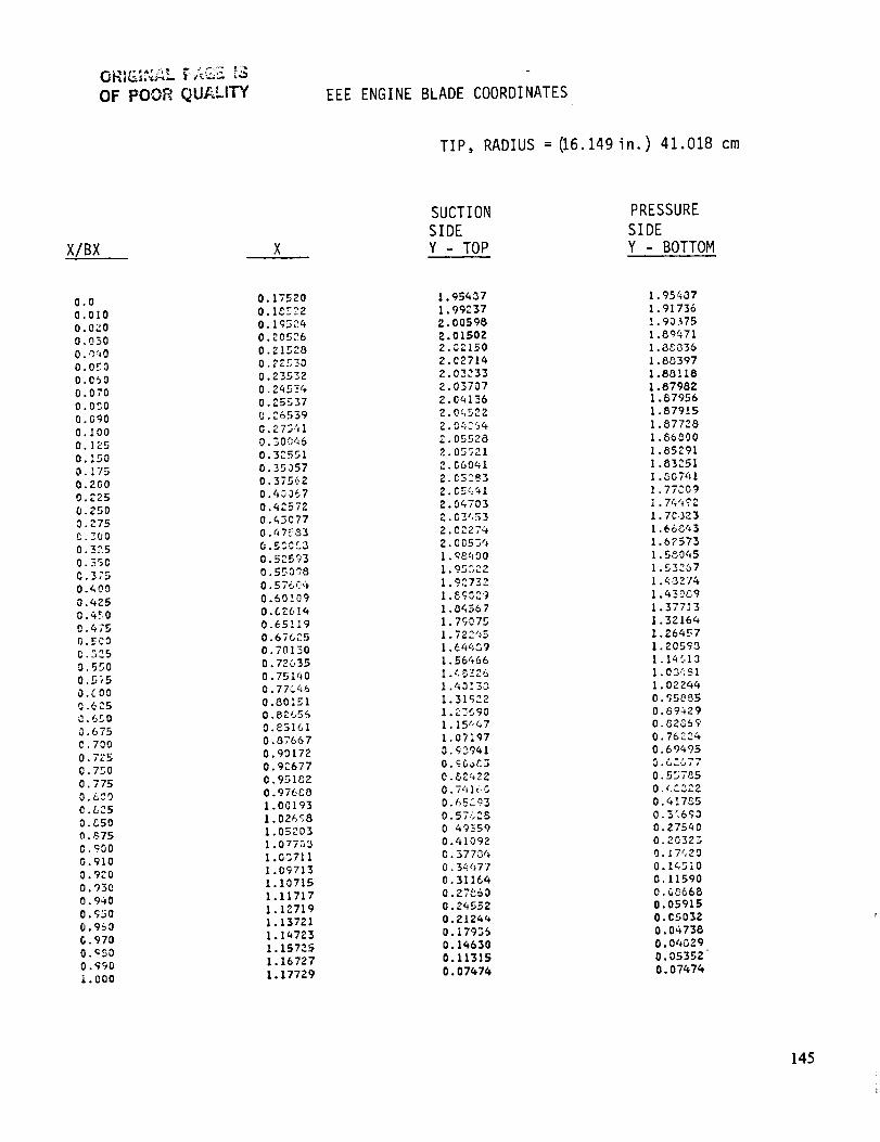
OF POOR QUALITY EEE ENGINE BLADE COORDINATES
TIP, RADIUS = 06.149 in.) 41.018 cm
XIBX
SUCTION PRESSURE
SIDE SIDEY - TOP Y - BOTTOM
0.0
0.010
0.020
0 030
0 ,'Y_O
0 0_3
0 060
O 070
00CO
0 GgO
0 100
0 ]25
0:5O
0 175
0 200
0 225
0.250
0 • ?75
C. 7.00
0.3,'1.5
O. 350
0.3;'5
0._,00
0.425
0.450
0.475
G.EC3
.5:5
0.550
0.575
O.COO
0.b25
0.650
0.675
0,700
O. 7;:5
0.750
O. 775
0.6CO
0 .L,25
0.C50
O.._75
0.';00
0.910
0.900
0,930
0.940
O.gSO
0.950
G .970
0._500 .<;gO
i.000
O. 17520
0.1_22
0. I g_24
0.20526
0.21528
0.22_30
0.23532
0.2qSE4
0.25537
0.26539
O. _.75.11
O. 300_6
0.3"_551
0.35057
0.37562
0.43367
0,4," 57_'
0._3077
0.47:-33
0.530_3
0.525?3
0.550'_8
0.57604
0.50109
0.62614
0.65119
0.67_25
0.70130
0.72635
0.751Q0
0.776q5
0.801.51
0.82655
0.851GI
0.87667
0.90172
0.92677
O. 9_5282
0.976C0
1.00193
1.02_';8
1.05203
1.07733
1.0:3711
I .09713
1.10715
1.11717
1.12719
l. 13721
I •14723
1. 15725
I. 16727
1.17729
1. 95437
1.99237
2. 00598
2.015022.02,150
2.03714
2.03233
2,03707
2.04236
2.0q523
2,0_:34
,?.. 05538
2.05_21
2. G60_l
2.e5__3
2. c_4_1
2.0c,703
2.03"153
2. 02274
2. 0053t_
l. <_SqO 0
1.95.322
1.92732
1.6g0_9
I .04567
I. 7-3075
I. 722_5
1.6td>89
1.56466
I .Q3138
1.31932
I. 15,!47
1.07i97
O. _3941
0.&24220.741(,5
0.65093
0.57325
0 49359
0.41092
O. 37704
0. 34477
0.31164
0.27_60
0.24552
0.2124_,
0. i7935
0. 14630
0.11315
O. 07474
!. 95407
I. 91736
!. 90375
I .89_71
I ._$036
1.88397
1.88118
1.87982
1.87956
1.87915
1.87728
I .86500
I .85291
I .83251I ._0741
I .77C09
I. 7_',:+_ 2
1. 70323
1.668_3
1.6?573
1.5o045
1,53257
I .48274
1 43089
1 377I 3
1 32164
1 264_r-7
1 20593
I I_{.i 3
I 03CS1
1 02244
0 gS_B5
0 89429
0.B2059
0. 767:.34
0,69495
0.62077
O.5D7P_5
0 ,_:C3Z2
0,417_5
0,316<;0
0,275_0
0.20323
0. _ 7420
0.I_510
0.11590
O. G_6680.05915
0,05032
0.04 738
0.04G39
0.05352
0.07_7_
14.5

OF POOR QUAL|_
A
ACC
ADP
amb.
Btu
CET
CpB
Cx
D
FP
FPS
HPC
HPT
IC/LS
ID
LE
LPT
M, Mn
N
N2
OAS
OD
P
PF
A P/P, Pr
APPENDIX B
LIST OF SYMBOLS
Annulus area
Active clearance control
Aerodynamic design point
Ambient
British thermal unit
Combustor exit temperature
Base pressure coefficient
Axial flow velocity
Di ame ter
Flow parameter, W_FT-/P
Flight propulsion system
High-pressure compressor
High-pressure turbi ne
Integrated core/low spool
Inner diameter
Leading edge
Low-pressure turbine
Mach number
Mechanical speed, rpm
High-pressure rotor speed,
Outer airseal
Outer diameter
Pressure
Patter ,_factor
Pressure ratio
r1_m
146

PT
R
rpm
S
SLTO
T
TE
TOBI
U
Urim
Wae
Wc/a
LIST OF SYMBOLS (Continued)
Total pressure
Rankine
Revolutions per minute
Span
Sea level take-off
Temperature
Trail ing edge
Tangential on-board injection
Tangential wheel speed
Rim speed
Engine airflow
Total cooling airflow
0
A
6
CT
Angle
Angle
Delta
Deflection
Efficiency
Stress
147
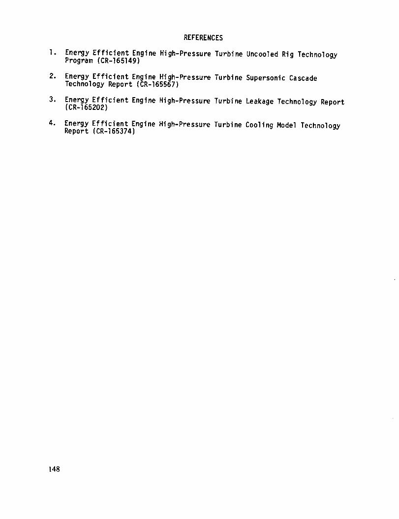
REFERENCES
I. Energy Efficient Engine High-Pressure Turbine Uncooled Rig Technology
Program (CR-165149)
2. Energy Efficient Engine High-Pressure Turbine Supersonic CascadeTechnology Report (CR-165567)
3. Energy Efficient Engine High-Pressure Turbine Leakage Technology Report(CR-165202)
4. Energy Efficient Engine High-Pressure Turbine Cooling Model TechnologyReport (CR-165374)
148
DISTRIBUTION LIST
GOVERNMENT AGENCI ES
NASA Headquarters600 Independence Ave., SWWashington, D.C. 20546Attention: RTP-6/R.S. Colladay
RTP-6/C .C. RosenRTP-6/L. HarrisRRP-6/J. FaceyLibrary
NASA-Lewis Research Center21000 Brookpark RoadCleveland, OH 44135Attention: D. L. Nored
C. C. CiepluchJ. W. SchaeferP. G. BattertonG. K. Sievers
LibraryReport Control OfficeTech Utilization OfficeM. A. BeheimM. J. HartmannR. A. RudeyR. A. WeberW. C. StrackT. P. MoffittJ. E. RohdeR. L. Dreshfield
A. LongW. M. BraithwaiteL. ReidAFSC Liaison OfficeArmy R&T Propulsion Lab
MS 301-2MS 301-4 (20 copies)MS 30i-4MS 301-4MS 301-2MS 60-3 (2 copies)MS 5-5MS 3-19MS 3-5MS 5-3MS 60-4MS 500-127MS 501-10MS 77-2MS 77--2MS 105-1MS 500-305MS 500-208MS 5-9MS 501-3MS 302-2
149
NASA-Lewis Research Center
21000 Brookpark RoadCleveland, Ohio 44135Attention: D.L. Nored MS 301-2
NASA-Lewis Research Center
21000 Brookpark Road
Cleveland, Ohio 44135Attention: R.J. Weber
NASA-Lewis Research Center
21000 Brookpark Road
Cleveland, Ohio 44135
Attention: C.C. Ciepluch MS 301-4
20 CopiesNASA-Lewis Research Center
21000 Brookpark Road
Cleveland, Ohio 44135Attention: J.W. Schaefer MS 301-4
NASA-Lewis Research Center
21000 Brookpark Road
Cleveland, Ohio 44135Attention: W.C. Strack
NASA-Lewis Research Center
21000 Brookpark Road
Cleveland, Ohio 44135Attention: T.P. Moffitt
NASA Lewis Research Center
21000 Brookpark RoadCleveland, Ohio 44135Attention: P.G. Batterton
NASA-Lewis Research Center
21000 Brookpark RoadCleveland, Ohio 44135
MS 301-4 Attention: J.E. Rohde
NASA-Lewis Research Center
21000 Brookpark Road
Cleveland, Ohio 44135Attention: G.M. Sievers MS 301-2
NASA-Lewis Research Center
21000 Brookpark RoadCleveland, Ohio 44135
Attention: R. L. Dreshfield
NASA-Lewis Research Center
21000 Brookpark Road
Cleveland, Ohio 44135
Attention: Library MS 60-3
2 CopiesNASA-Lewis Research Center
21000 Brookpark Road
Cleveland, Ohio 44135
Attention: Report Control Office
NASA-Lewis Research Center
21000 Brookpark Road
Cleveland, Ohio 44135
Attention: A. Long
NASA-Lewis Research Center
21000 Brookpark Road
Cleveland, Ohio 44135MS 5-5 Attention: W.M. Braithwaite
NASA-Lewis Research Center
21000 Brookpark Road
Cleveland, Ohio 44135Attention: Tech Utilization Office
MS 3-19
NASA-Lewis Research Center
21000 Brookpark RoadCleveland, Ohio 44135
Attention: M.A. Beheim MS 3-5
NASA-Lewis Research Center
21000 Brookpark RoadCleveland, Ohio 44135
Attention: M.J. Hartmann MS 3-7
NASA-Lewis Research Center
21000 Brookpark Road
Cleveland, Ohio 44135
Attention: R.A. Rudey MS 86-5
NASA-Lewis Research Center
21000 Brookpark RoadCleveland, Ohio 44135
Attention: L. Reid
NASA-Lewis Research Center
21000 Brookpark RoadCleveland, Ohio 44135
Attention: AFSC Liaison Office
NASA-Lewis Research Center
21000 Brookpark RoadCleveland, Ohio 44135
Attention: Army R&T Propulsion
NASA Ames Research Center
Moffett Field, CA 94035
Attention: 202-7/M. H. Waters
Library
MS 500-127
MS 501-10
MS 77-2
MS 77-2
MS 105-1
MS 500-305
MS 500-208
MS 5-9
MS 501-3
MS 302-2
150
NASA Langley Research CenterLangley Field, VA 23365Attention: R. Leonard
D. I_ai denL. J. WilliamsLibrary
NASA Dryden Flight Research CenterP.O. Box 273
Edwards, CA 93523Attention: J. A. A lbers
Library
NASA Scientific and Technical InformationF aci I ity
P.O. Box 8757B.W.I. Airport, MD 21240Attention: Acquisition Branch (i0 copies)
Department of DefenseWashington, D.C. 2U301Attention: R. Standahar 3DI089 Pentagon
Wright-Patterson Air Force BaseDayton, Ohio 45433Attention: APL Chief Scientist A_WAL/PS
Wright-Patterson Air Force BaseDayton, Ohio 45433Attention: E.E. Abell ASD/YZE
Wright-Patterson Air Force Base
Dayton, Ohio 45433Attention: H.I. Bush AFWAL/POT
Wright-Patterson Air Force BaseDayton, Ohio 45433Attention: E.E. Bailey (NASA Liaison)
A_WAL/NASA
Wright-Patterson Air Force Base
Dayton, Ohio 45433Attention: R.P. Carmichael ASD/XRHI
Wright-Patterson Air Force BaseDayton, Ohio 45433Attention: R. Ellis ASD/YZN
Wright-Patterson Air Force BaseDayton, Ohio 45433Attention: W.H. Austin, Jr. ASD/ENF
Eustis Directorate
U.S. Army Air Mobility
R&D LaboratoryFort Eustis, VA 23604
Attention: J. Lane, SAVDL-EU-Tapp
Navy DepartmentNaval Air Systems CommandWashington, D. C. 20361Attention: W. Koven AIR-O3E
Navy DepartmentNaval Air Systems CommandWashington, D. C. 20361Attention: J.L. Byers AIR-53602
Navy DepartmentNaval Air Systems CommandWashington, D. C. 20361Attention: E.A. Lichtman AIR-330E
Navy DepartmentNaval Air Systems CommandWashington, D. C. 20361Attention: G. Derderian AIR-5362C
NAVAL AIR Propulsion Test CenterTrenton, NJ 08628
Attention: J. J. CurryA. A. Martino
U.S. Naval Air Test Center
Code SY-53
Patuxent River, MD 20670
Attention: E. A. Lynch
USAVRAD C_nmandPO Box 209
St. Louis, MO 63166
Attention: Ropbert _. Titus (ASTIO)
Department of TransportationNASA/DOT Joint Office of Noise Abatement
Washington, D.C. 20590Attention: C. Foster
Federal Aviation AdministrationNoise Abatement Division
Washington, D.C. 20590Attention: E. Sellman AEE-120
Environmental Protection Agency1835 K Street, NWWashington, D.C. 2{]460Attention: J. Schettino
J. Tyler
Environmental Protection Agency2565 Plymouth Road
Ann ArDor, MI 481U5Attention: R. Munt
151
Federal Aviation Administration
12 New England Executive ParkBurlington, MA 18083Attention: Jack A. Sain, ANE-200
Curtiss Wright Corporation
Woodridge, NJ 07075Attention: S. Lombardo
S. Moskowitz
Detroit Diesel Allison Div. G.M.C.P.O. Box 894
Indianapolis, IN 46206Attention: W. L. Mclntire
Cummins Engine Co.Technical Center
500 S. PoplarColunW)us, IN 47201Attention: J. R. Drake
AVCO/Lycoming550 S. Main Street
Stratford, CT 06497Attention: H. Moellmann
Detroit Diesel Allison Div. G.M.C.333 West First Street
Dayton, Ohio 45402Attention: F. H. Walters
The Garrett Corporation
AIResearch Manufacturing Co.Torrance, CA 90509Attention: F. E. Faulkner
The Garrettt Corportion
AIResearch Manufacturing Co.402 S. 36 Street
Phoenix, AZ 85034
Attention: Library
General Electric Co./AEG
One Jimson Road
Evendale, Ohio 45215
Attention: R.W. Bucy (3 copies)T. F. Donohue
Pratt & Whitney Aircraft Group/UTCGovernment Products DivisionP.O. Box 2691
West Palm Beach, F] 33402
Attention: B. A. Jones
152
The Garrettt CorportionAIResearch Aviation Co.
19201Susana Road
Compton, CA 90221Attention: N. J. Palmer
AIResearch Manufacturing Co.111 South 34th Street
P.O. Box 5217
Phoenix, AZ 85010
Attention: C. E. Corrigan(93-120/503-4F)
Williams Research Co.
2280 W. Maple RoadWalled Lake, MI 48088
Attention: R. VanNimwegenR. Horn
Teledyne CAE, Turbine Engines1330 Laskey Road
Tolendo, Ohio 43612
Attention: R. H. Gaylord
General Electric Co./AEG1000 Western Ave.
Lynn, MA 01910Attention: R. E. Neitzel
Pratt & Whitney Aircraft Group/UTCCommercial Products Division
East Hartford, Ct 06108Attention: W. Gardner
I. Mendelson
Boeing Commercial Airplane Co.P.O. Box 3707
Seattle, WA 98124
Attention: P. E. Johnson MS 9H-46
D. C. Nordstrom MS 73-01
Boeing Aerospace Co.P.O. Box 3999
Seattle, Wa 98124
Attention: D. S. Miller MS 40-26
H. Higgins
The Boeing Co., Wichita Division
Wichita, KS 67210Attention: D. Tarkelson
Douglas Aircraft Company
McDonnell Douglas Corp.3855 Lakewood Boulevard
Long Beach, CA 90846
Attention: R. T. Kawai Code 36-41
M. Klotzsche

Lockheed California Co.
Burbank, CA 91502Attention: J. F. Stroud, Dept. 75-42
R. Tullis, Dept. 75-21J. I. Benson
General Dynamics ConvairP. O. Box 80847
San Diego, CA 92138
Attention: S. Campbell, MZ 632-00
Rockwell International
International Airport
Los Angeles Division
Los Angeles, CA 90009Attention: A. W. Martin
Gates Learjet Corp.P. O. Box 7707
Wichita, KS 67277Attention: E. Schiller
McDonnell Aircraft Co.
McDonnell Douglas Corp.P. O. Box 516
St. Louis, MO 63166
Attention: F. C. Claser Dept. 243
Lockheed Georgia Co.
Marietta, GA 30060Attention: H. S. Sweet
Gru_nan Aerospace Corp.
South Oyster Bay Road
Bethpage, New York 11714Attention: C. Hoeltzer
American Airlines
Maint. & Engr. Center
Tulsa, OK 74151
Attention: W. R. Neeley
Eastern Airlines
International Airport
Miami, FL 33148Attention: A. E. Fishbein
Delta Airlines, Inc.
Hartsfield-Atlanta International AirportAtlanta, GA 30320Attention: C. C. Davis
TransWorld Airlines
605 Third Avenue
New York, NY 10016Attention: A. E. Carrol
Pan American World Airways, Inc.
JFK International Airport
Jamica, NY 11430
Attention: J. G. Borger
A. MacLarty
United Airlines
San Francisco International Airport
Maint. Operations Center
San Francisco, CA 94128Attention: J. J. Overton
Hamilton Standard
Bradley FieldWindsor Locks, CT 06096
Attention: P. J. Dumais, MS 1A-3-I
A. T. Reiff, MS 1-2-2
FluiDyne Engineering Corp.
5900 Olson Metmrial Highway
Minneapolis, MN 55422Attention: J. S. Holdhusen
Rohr CorporationP.O. Box 878
Foot & H Street
Chula Vista, CA 92012
Attention: Library
Solar Division
International Harvester
2200 Pacific Highway
San Diego, CA 92112
Attention: Library
Gas Dynamics Laboratories
Aerospace Engineering BuildingUniversity of MichiganAnn Arbor, MI 48109Attention: Dr. C. W. Kaufmann
Massachusetts Inst. of TechnologyDept. of Astronautics & Aeronautics
Cambridge, MA 02139Attention: Jack Kerrebrock
Massachusetts Inst. of TechnologyDept. of Structural Mechanics
Ca_ridege, MA 02139Attention: Jat_s Mar
Westinghouse Electric Corp.P.O. Box 5837Beulah Road
Pittsburgh, PA 15236
Attention: Library
1s3 [
University of Tennessee
Space InstituteTullahoma, TN 37388Attention: Dr. V. Smith
TRW Equipment GroupTRW Inc.
23555 Euclid Ave.
Cleveland, OH 44117Attention: I. Toth
Aerospace CorporationR & D Center
Los Angeles, CA 90045Attention: Library
George ShevlinP.O. Box 1925
Washington, D.C. 20013
Brunswick Corporation2000 Brunswick Lane
Deland, Fl 32720Attention: A. Erickson
Pennsylvania State University
Depart1_nt of Aerospace Engineering
233 Ha,_nond BuildingUniversity Park, Pennsylvania 16802
Attention: Dr. B. Lakshminarayana
Iowa State University
Department ;of Mechanical Engineering
Ames, Iowa 50011
Attention: Dr. Patrick Kavanagh
Detroit Diesel Allison
P.O. Box 894
Indianapolos, Indiana 46206Attention: Mr. Robert Delanie
Speed Code U29AMr. H. L. Stocker
Speed Code U21A
KVB Inc*
18006 Skypark Blvd.P.O. Box 19518
Irvine CA 92714
Attention: A. M. Mellor
154