Embed Size (px)
Citation preview
N-750Configuration Guide
Version 1.0
TD9005October 1997 Revision 1.0

Version 1.0 October 1997
N-750 Configuration Guide
Version 1.0 October 1997
N-750 Configuration GuideN-750 Configuration Guide
Contents
Introduction ...............................................................................1Features ....................................................................................2UL Approvals and Agency Listings ............................................2Compatible UL Listed Receivers ...............................................2Partitioning ................................................................................3N-750 Dial Up Installation With On-Board Communicator ..........4N-750 Dial Up Installation ..........................................................6N-750 Direct Connect Installation ..............................................8N-750 Compatible Reader and Card Formats ......................... 10Device Worksheet ................................................................... 11Worksheet for Auxiliary Devices .............................................. 12Glossary of Terms and Definitions ........................................... 13
Version 1.0 October 1997
N-750 Configuration Guide
N-750 Configuration Guide
1Version 1.0 October 1997
IntroductionThis guide is designed to help understand the N-750 panel and theprocess of assembling a complete system.
The N-750 is a control/communicator for use in commercialsecurity and fire applications, with a built-in communicator forreporting to most central stations. The N-750 includes asophisticated access control system, through which you canmonitor and control user access to specified areas of a building.The benefit of the N-750 is that three separate systems are nolonger needed, everything is included in one panel.
The N-750 is ideal for colleges and universities, hospitals, shop-ping malls, warehouses, office towers, business campuses, seniorhousing, storage facilities, banks, airports, or wherever there is riskinvolved.
2Version 1.0 October 1997
N-750 Configuration Guide
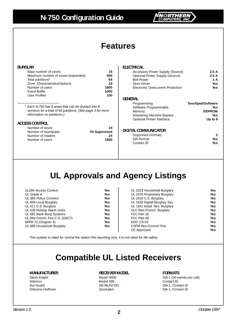
BURGLARBase number of zones 16Maximum number of zones (expanded) 400Total partitions* 64Zone Characteristics/Options 19Number of users 1800Event Buffer 1000User Profiles 100
* Each N-750 has 8 areas that can be divided into 8sections for a total of 64 partitions. (See page 3 for moreinformation on partitions.)
ACCESS CONTROLNumber of doors 24Number of touchpads 24 SupervisedNumber of readers 24Number of users 1800
ELECTRICALAccessory Power Supply (Source) 2.5 AOptional Power Supply (Source) 2.5 ABell Power 1 ASiren Driver YesElectronic Overcurrent Protection Yes
GENERALProgramming Touchpad/SoftwareSoftware Programmable YesMemory EEPROMAnswering Machine Bypass YesOptional Printer Interface Up to 8
DIGITAL COMMUNICATORSupported Formats 2SIA Format YesContact ID Yes
UL294 Access Control YesUL Grade A YesUL 365 Police Connect YesUL 609 Local Burglary YesUL 611 C.S. Burglary YesUL 636 Holdup Alarm Units YesUL 681 Bank Burg Systems YesUL 864 Comm. Fire C.S. (DACT) YesNFPA 72 (Chapter 4) YesUL 985 Household Burglary Yes
UL 1023 Household Burglary YesUL 1076 Proprietary Burglary YesUL 1610 C.S. Burglary YesUL 1635 Digital Burglary Sys. YesUL 1641 Instal. Res. Burglary YesULC Res./Comm. Burglary YesFCC Part 15 YesFCC Part 68 YesDOC CS-03 YesCSFM Res./Comm/ Fire YesCE Approved Yes
Features
UL Approvals and Agency Listings
Compatible UL Listed Receivers
MANUFACTURER RECEIVER MODEL FORMATSSilent Knight Model 9000 SIA-1 (20 events per call)Ademco Model 685 Contact IDSur-Guard SG-MLR2-DG SIA-1, Contact IDOsborne Hoffman Quickalert SIA-1, Contact ID
This system is rated for central fire station fire reporting only. It is not rated for life safety.
N-750 Configuration Guide
3Version 1.0 October 1997
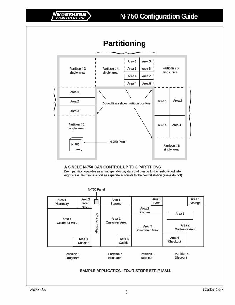
Partitioning
N-750
Area 1
Area 2
Area 3
Partition #3single area
Partition #6single area
Area 1 Area 2
Area 3 Area 4
Partition #4single area
Area 1
Area 2
Area 3
Area 4
Area 5
Area 6
Area 7
Area 8
Partition #1single area
Partition #8single area
Dotted lines show partition borders
A SINGLE N-750 CAN CONTROL UP TO 8 PARTITIONSEach partition operates as an independent system that can be further subdivided intoeight areas. Partitions report as separate accounts to the central station (areas do not).
SAMPLE APPLICATION: FOUR-STORE STRIP MALL
Area 3
Partition 1Drugstore
Partition 2Bookstore
Partition 3Take-out
Partition 4Discount
Area 1Storage
Area 1Pharmacy
Area 4Customer Area
Area 3Cashier
Area 2Customer Area
Area 3Cashier
Area 5 S
torage
N-750 Panel
Area 1Safe
Area 2Kitchen
Area 3Customer Area
Area 1Storage
Area 4Checkout
Area 2Customer Area
N-750 Panel
Area 2Post
Office
4Version 1.0 October 1997
N-750 Configuration Guide
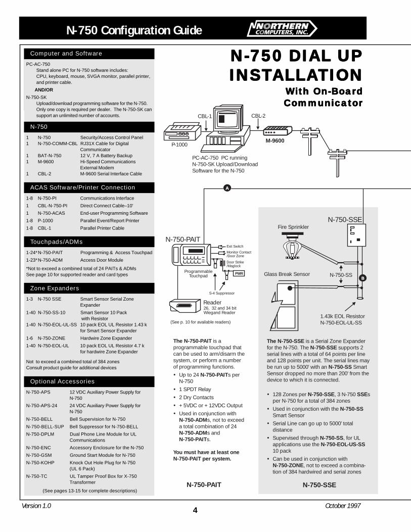
N-750 DIAL UPN-750 DIAL UPN-750 DIAL UPN-750 DIAL UPN-750 DIAL UPINSTINSTINSTINSTINSTALLAALLAALLAALLAALLATIONTIONTIONTIONTION
With On-BoardWith On-BoardWith On-BoardWith On-BoardWith On-BoardCommunicatorCommunicatorCommunicatorCommunicatorCommunicator
Computer and Software
PC-AC-750Stand alone PC for N-750 software includes:CPU, keyboard, mouse, SVGA monitor, parallel printer,and printer cable.
AND/OR
N-750-SKUpload/download programming software for the N-750.Only one copy is required per dealer. The N-750-SK cansupport an unlimited number of accounts.
N-750
1 N-750 Security/Access Control Panel1 N-750-COMM-CBL RJ31X Cable for Digital
Communicator1 BAT-N-750 12 V, 7 A Battery Backup1 M-9600 Hi-Speed Communications
External Modem1 CBL-2 M-9600 Serial Interface Cable
ACAS Software/Printer Connection
1-8 N-750-PI Communications Interface
1 CBL-N-750-PI Direct Connect Cable–10'
1 N-750-ACAS End-user Programming Software
1-8 P-1000 Parallel Event/Report Printer
1-8 CBL-1 Parallel Printer Cable
Touchpads/ADMs
1-24*N-750-PAIT Programming & Access Touchpad
1-23*N-750-ADM Access Door Module
*Not to exceed a combined total of 24 PAITs & ADMsSee page 10 for supported reader and card types
Zone Expanders
1-3 N-750 SSE Smart Sensor Serial ZoneExpander
1-40 N-750-SS-10 Smart Sensor 10 Pack with Resistor
1-40 N-750-EOL-UL-SS 10 pack EOL UL Resistor 1.43 kfor Smart Sensor Expander
1-6 N-750-ZONE Hardwire Zone Expander
1-40 N-750-EOL-UL 10 pack EOL UL Resistor 4.7 kfor hardwire Zone Expander
Not to exceed a combined total of 384 zonesConsult product guide for additional devices
Optional Accessories
N-750-APS 12 VDC Auxiliary Power Supply forN-750
N-750-APS-24 24 VDC Auxiliary Power Supply forN-750
N-750-BELL Bell Supervision for N-750
N-750-BELL-SUP Bell Suppressor for N-750-BELL
N-750-DPLM Dual Phone Line Module for ULCommunications
N-750-ENC Accessory Enclosure for the N-750
N-750-GSM Ground Start Module for N-750
N-750-KOHP Knock Out Hole Plug for N-750(UL 6 Pack)
N-750-TC UL Tamper Proof Box for X-750Transformer
(See pages 13-15 for complete descriptions)
The N-750-PAIT
N-750-PAIT
N-750-ADM
N-750-ADMN-750-PAIT
You must have at least oneN-750-PAIT per system.
is aprogrammable touchpad thatcan be used to arm/disarm thesystem, or perform a numberof programming functions.
Up to 24 s perN-7501 SPDT Relay2 Dry Contacts+5VDC or +12VDC OutputUsed in conjunction with
s, not to exceeda total combination of 24
s ands.
N-750-PAIT
Reader
Exit Switch
Monitor Contact/Door Zone
Door Strike/Maglock
PWR
26, 32 and 34 bitWiegand Reader
N-750-SSE
ProgrammableTouchpad
CBL-1
P-1000
CBL-2
M-9600
PC-AC-750 PC runningN-750-SK Upload/DownloadSoftware for the N-750
N-750-PAIT
The N-750-SSEN-750-SSE
N-750-SS
N-750-SSE SSE
N-750-SS
N-750-SSN-750-EOL-US-SS
N-750-ZONE
is a Serial Zone Expanderfor the N-750. The supports 2serial lines with a total of 64 points per lineand 128 points per unit. The serial lines maybe run up to 5000' with an SmartSensor dropped no more than 200' from thedevice to which it is connected.
128 Zones per , 3 N-750 sper N-750 for a total of 384 zones
Used in conjunction with theSmart SensorSerial Line can go up to 5000' totaldistance
Supervised through , for ULapplications use the10 packCan be used in conjunction with
, not to exceed a combina-tion of 384 hardwired and serial zones
N-750-SS
1.43k EOL ResistorN-750-EOL-UL-SS
Fire Sprinkler
Glass Break Sensor
A
B
(See p. 10 for available readers)
N-750-SSE
S-4 Suppressor
N-750 Configuration Guide
5Version 1.0 October 1997
Brown
Gray
Green
Red
Premises
TIP
Premises
Ring
TelcoTip
TelcoRing
N-750-ACAS & N-750-PI
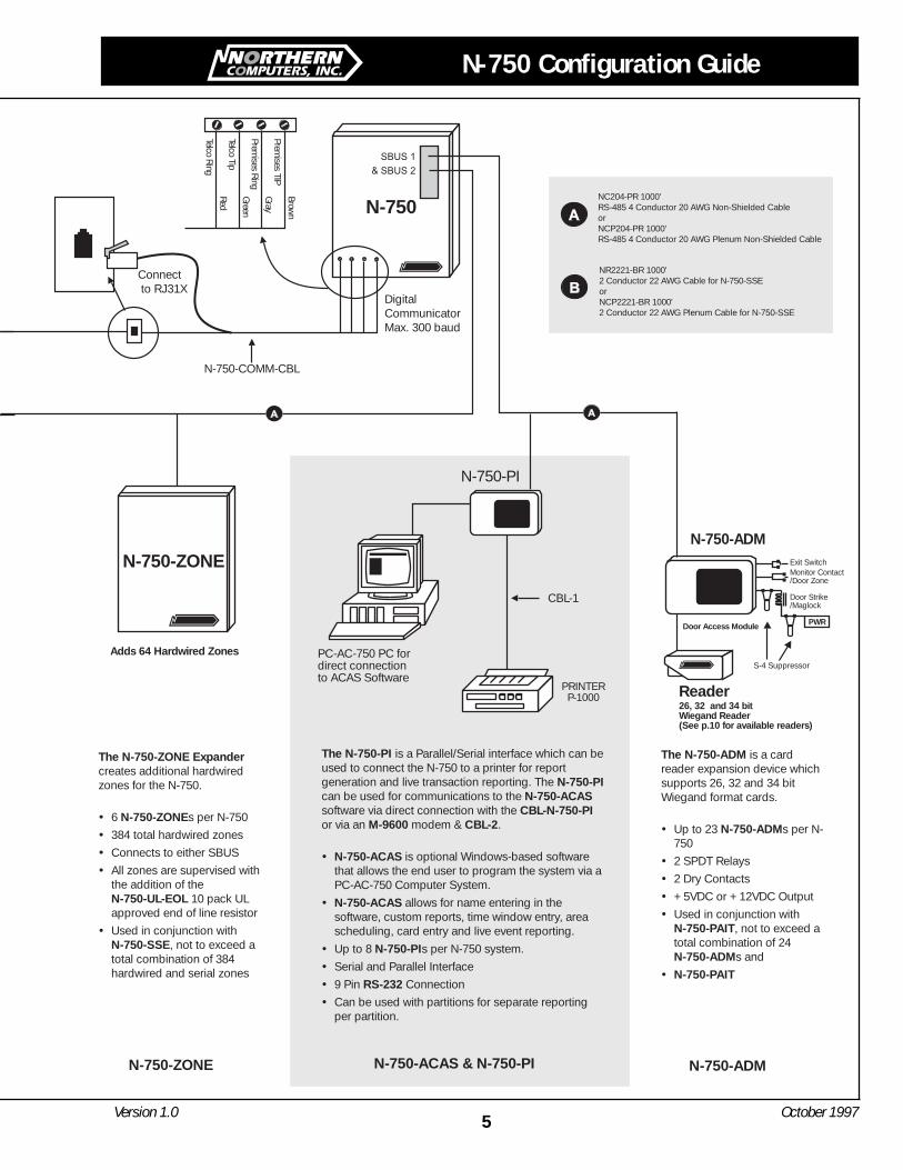
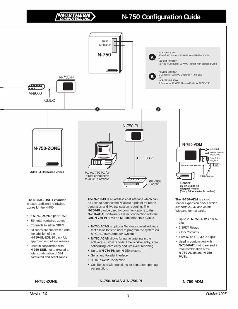
The N-750-ZONE Expander
N-750-ZONE
N-750-UL-EOL
N-750-SSE
creates additional hardwiredzones for the N-750.
6 s per N-750
384 total hardwired zones
Connects to either SBUS
All zones are supervised withthe addition of the
10 pack ULapproved end of line resistor
Used in conjunction with, not to exceed a
total combination of 384hardwired and serial zones
N-750-ZONE
Door Access Module
The N-750-ADM
N-750-ADM
N-750-PAIT
N-750-ADM
N-750-PAIT
is a cardreader expansion device whichsupports 26, 32 and 34 bitWiegand format cards.
Up to 23 s per N-750
2 SPDT Relays
2 Dry Contacts
+5VDC or +12VDC Output
Used in conjunction with, not to exceed a
total combination of 24s and
Reader26, 32 and 34 bitWiegand Reader(See p.10 for available readers)
N-750-ADMN-750-ZONE
Adds 64 Hardwired Zones
N-750
NR2221-BR 1000'2 Conductor 22 AWG Cable for N-750-SSEorNCP2221-BR 1000'2 Conductor 22 AWG Plenum Cable for N-750-SSE
N-750-ADM
NC204-PR 1000'RS-485 4 Conductor 20 AWG Non-Shielded CableorNCP204-PR 1000'RS-485 4 Conductor 20 AWG Plenum Non-Shielded Cable
N-750-COMM-CBL
The N-750-PI
N-750-PIN-750-ACAS
CBL-N-750-PIM-9600 CBL-2
N-750-ACAS
N-750-ACAS
N-750-PI
RS-232
is a Parallel/Serial interface which can beused to connect the N-750 to a printer for reportgeneration and live transaction reporting. Thecan be used for communications to thesoftware via direct connection with theor via an modem & .
is optional Windows-based softwarethat allows the end user to program the system via aPC-AC-750 Computer System.
allows for name entering in thesoftware, custom reports, time window entry, areascheduling, card entry and live event reporting.
Up to 8 s per N-750 system.
Serial and Parallel Interface
9 Pin Connection
Can be used with partitions for separate reportingper partition.
PRINTERP-1000
PC-AC-750 PC fordirect connectionto ACAS Software
N-750-PI
CBL-1
Connectto RJ31X
DigitalCommunicatorMax. 300 baud
Exit SwitchMonitor Contact/Door Zone
Door Strike/Maglock
PWR
S-4 Suppressor
6Version 1.0 October 1997
N-750 Configuration Guide
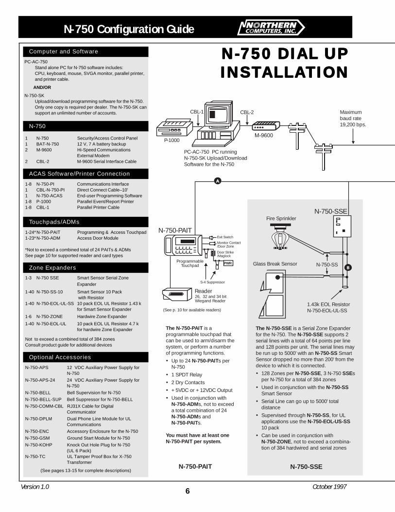
N-750 DIAL UPN-750 DIAL UPN-750 DIAL UPN-750 DIAL UPN-750 DIAL UPINSTINSTINSTINSTINSTALLAALLAALLAALLAALLATIONTIONTIONTIONTION
Computer and Software
PC-AC-750Stand alone PC for N-750 software includes:CPU, keyboard, mouse, SVGA monitor, parallel printer,and printer cable.
AND/OR
N-750-SKUpload/download programming software for the N-750.Only one copy is required per dealer. The N-750-SK cansupport an unlimited number of accounts.
N-750
1 N-750 Security/Access Control Panel1 BAT-N-750 12 V, 7 A battery backup2 M-9600 Hi-Speed Communications
External Modem2 CBL-2 M-9600 Serial Interface Cable
ACAS Software/Printer Connection
1-8 N-750-PI Communications Interface1 CBL-N-750-PI Direct Connect Cable–10'1 N-750-ACAS End-user Programming Software1-8 P-1000 Parallel Event/Report Printer1-8 CBL-1 Parallel Printer Cable
Touchpads/ADMs
1-24*N-750-PAIT Programming & Access Touchpad1-23*N-750-ADM Access Door Module
*Not to exceed a combined total of 24 PAITs & ADMsSee page 10 for supported reader and card types
Zone Expanders
1-3 N-750 SSE Smart Sensor Serial ZoneExpander
1-40 N-750-SS-10 Smart Sensor 10 Pack with Resistor
1-40 N-750-EOL-UL-SS 10 pack EOL UL Resistor 1.43 kfor Smart Sensor Expander
1-6 N-750-ZONE Hardwire Zone Expander
1-40 N-750-EOL-UL 10 pack EOL UL Resistor 4.7 kfor hardwire Zone Expander
Not to exceed a combined total of 384 zonesConsult product guide for additional devices
Optional Accessories
N-750-APS 12 VDC Auxiliary Power Supply forN-750
N-750-APS-24 24 VDC Auxiliary Power Supply forN-750
N-750-BELL Bell Supervision for N-750
N-750-BELL-SUP Bell Suppressor for N-750-BELL
N-750-COMM-CBL RJ31X Cable for DigitalCommunicator
N-750-DPLM Dual Phone Line Module for ULCommunications
N-750-ENC Accessory Enclosure for the N-750
N-750-GSM Ground Start Module for N-750
N-750-KOHP Knock Out Hole Plug for N-750(UL 6 Pack)
N-750-TC UL Tamper Proof Box for X-750Transformer
(See pages 13-15 for complete descriptions)
CBL-1
P-1000
CBL-2
PC-AC-750 PC runningN-750-SK Upload/DownloadSoftware for the N-750
Maximumbaud rate19,200 bps.
The N-750-PAIT
N-750-PAIT
N-750-ADM
N-750-ADMN-750-PAIT
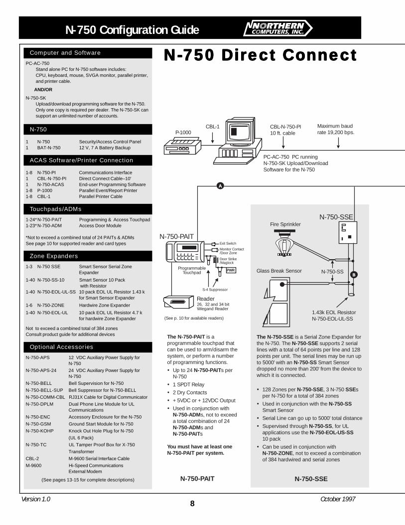
You must have at least oneN-750-PAIT per system.
is aprogrammable touchpad thatcan be used to arm/disarm thesystem, or perform a numberof programming functions.
Up to 24 s perN-7501 SPDT Relay2 Dry Contacts+5VDC or +12VDC OutputUsed in conjunction with
s, not to exceeda total combination of 24
s ands.
N-750-PAIT
Reader
Exit Switch
Monitor Contact/Door Zone
Door Strike/Maglock
PWR
26, 32 and 34 bitWiegand Reader
N-750-SSE
ProgrammableTouchpad
N-750-PAIT
The N-750-SSEN-750-SSE
N-750-SS
N-750-SSE SSE
N-750-SS
N-750-SSN-750-EOL-US-SS
N-750-ZONE
is a Serial Zone Expanderfor the N-750. The supports 2serial lines with a total of 64 points per lineand 128 points per unit. The serial lines maybe run up to 5000' with an SmartSensor dropped no more than 200' from thedevice to which it is connected.
128 Zones per , 3 N-750 sper N-750 for a total of 384 zones
Used in conjunction with theSmart SensorSerial Line can go up to 5000' totaldistance
Supervised through , for ULapplications use the10 packCan be used in conjunction with
, not to exceed a combina-tion of 384 hardwired and serial zones
N-750-SS
1.43k EOL ResistorN-750-EOL-UL-SS
Fire Sprinkler
Glass Break Sensor
(See p. 10 for available readers)
N-750-SSE
S-4 Suppressor
N-750 Configuration Guide
7Version 1.0 October 1997
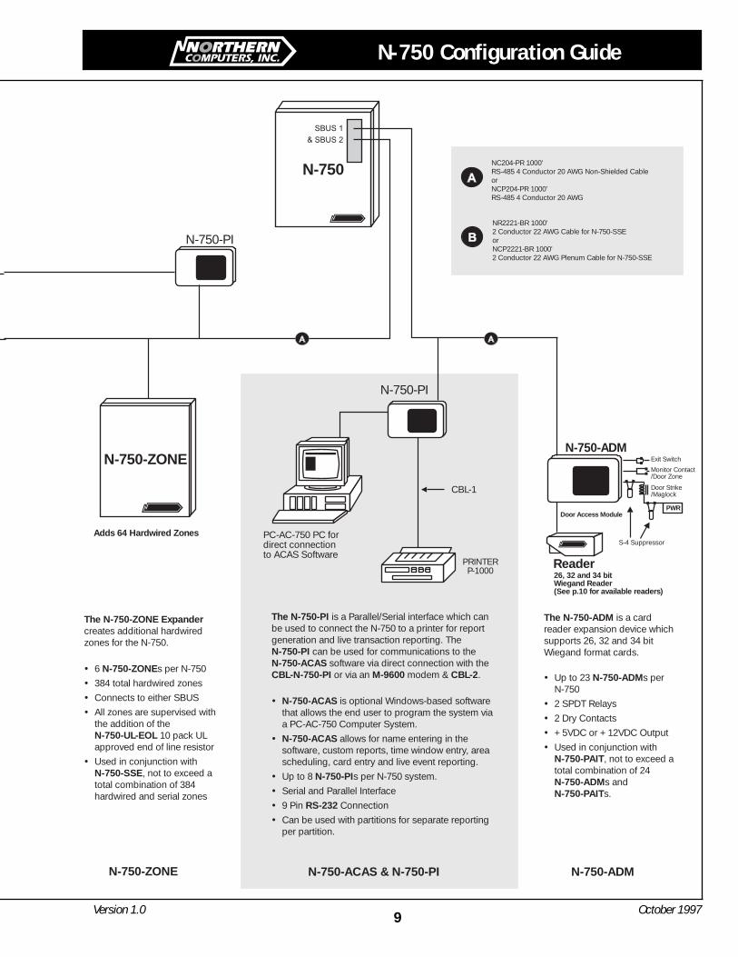
The N-750-ZONE Expander
N-750-ZONE
N-750-UL-EOL
N-750-SSE
creates additional hardwiredzones for the N-750.
6 s per N-750
384 total hardwired zones
Connects to either SBUS
All zones are supervised withthe addition of the
10 pack ULapproved end of line resistor
Used in conjunction with, not to exceed a
total combination of 384hardwired and serial zones
N-750-ZONE
Door Access Module
The N-750-ADM
N-750-ADM
N-750-PAIT
N-750-ADM N-750-PAIT
is a cardreader expansion device whichsupports 26, 32 and 34 bitWiegand format cards.
Up to 23 s per N-750
2 SPDT Relays
2 Dry Contacts
+5VDC or +12VDC Output
Used in conjunction with, not to exceed a
total combination of 24s and
s.
Reader26, 32 and 34 bitWiegand Reader(See p.10 for available readers)
N-750-ADMN-750-ZONE
Adds 64 Hardwired Zones
N-750
N-750-PINR2221-BR 1000'2 Conductor 22 AWG Cable for N-750-SSEorNCP2221-BR 1000'2 Conductor 22 AWG Plenum Cable for N-750-SSE
N-750-ADM
NC204-PR 1000'RS-485 4 Conductor 20 AWG Non-Shielded CableorNCP204-PR 1000'RS-485 4 Conductor 20 AWG Plenum Non-Shielded Cable
N-750-ACAS & N-750-PI
The N-750-PI
N-750-PIN-750-ACASCBL-N-750-PI M-9600 CBL-2
N-750-ACAS
N-750-ACAS
N-750-PI
RS-232
is a Parallel/Serial interface which canbe used to connect the N-750 to a printer for reportgeneration and live transaction reporting. The
can be used for communications to thesoftware via direct connection with theor via an modem & .
is optional Windows-based softwarethat allows the end user to program the system viaa PC-AC-750 Computer System.
allows for name entering in thesoftware, custom reports, time window entry, areascheduling, card entry and live event reporting.
Up to 8 s per N-750 system.
Serial and Parallel Interface
9 Pin Connection
Can be used with partitions for separate reportingper partition.
PRINTERP-1000
PC-AC-750 PC fordirect connectionto ACAS Software
N-750-PI
CBL-1
M-9600
CBL-2
Exit Switch
Monitor Contact/Door Zone
Door Strike/Maglock
PWR
S-4 Suppressor
8Version 1.0 October 1997
N-750 Configuration Guide
N-750 Direct ConnectN-750 Direct ConnectN-750 Direct ConnectN-750 Direct ConnectN-750 Direct Connect
CBL-1P-1000
CBL-N-750-PI10 ft. cable
PC-AC-750 PC runningN-750-SK Upload/DownloadSoftware for the N-750
Maximum baudrate 19,200 bps.
The N-750-PAIT
N-750-PAIT
N-750-ADM
N-750-ADMN-750-PAIT
You must have at least oneN-750-PAIT per system.
is aprogrammable touchpad thatcan be used to arm/disarm thesystem, or perform a numberof programming functions.
Up to 24 s perN-750
1 SPDT Relay
2 Dry Contacts
+5VDC or +12VDC Output
Used in conjunction withs, not to exceed
a total combination of 24s ands
N-750-PAIT
Reader
Exit Switch
Monitor Contact/Door Zone
Door Strike/Maglock
PWR
26, 32 and 34 bitWiegand Reader
N-750-SSE
ProgrammableTouchpad
N-750-PAIT
The N-750-SSEN-750-SSE
N-750-SS
N-750-SSE SSE
N-750-SS
N-750-SSN-750-EOL-US-SS
N-750-ZONE
is a Serial Zone Expander forthe N-750. The supports 2 seriallines with a total of 64 points per line and 128points per unit. The serial lines may be run upto 5000' with an Smart Sensordropped no more than 200' from the device towhich it is connected.
128 Zones per , 3 N-750 sper N-750 for a total of 384 zones
Used in conjunction with theSmart Sensor
Serial Line can go up to 5000' total distance
Supervised through , for ULapplications use the10 pack
Can be used in conjunction with, not to exceed a combination
of 384 hardwired and serial zones
N-750-SS
1.43k EOL ResistorN-750-EOL-UL-SS
Fire Sprinkler
Glass Break Sensor
(See p. 10 for available readers)
N-750-SSE
S-4 Suppressor
Computer and Software
PC-AC-750Stand alone PC for N-750 software includes:CPU, keyboard, mouse, SVGA monitor, parallel printer,and printer cable.
AND/OR
N-750-SKUpload/download programming software for the N-750.Only one copy is required per dealer. The N-750-SK cansupport an unlimited number of accounts.
N-750
1 N-750 Security/Access Control Panel1 BAT-N-750 12 V, 7 A Battery Backup
ACAS Software/Printer Connection
1-8 N-750-PI Communications Interface1 CBL-N-750-PI Direct Connect Cable–10'1 N-750-ACAS End-user Programming Software1-8 P-1000 Parallel Event/Report Printer1-8 CBL-1 Parallel Printer Cable
Touchpads/ADMs
1-24*N-750-PAIT Programming & Access Touchpad1-23*N-750-ADM Access Door Module
*Not to exceed a combined total of 24 PAITs & ADMsSee page 10 for supported reader and card types
Zone Expanders
1-3 N-750 SSE Smart Sensor Serial ZoneExpander
1-40 N-750-SS-10 Smart Sensor 10 Pack with Resistor
1-40 N-750-EOL-UL-SS 10 pack EOL UL Resistor 1.43 kfor Smart Sensor Expander
1-6 N-750-ZONE Hardwire Zone Expander
1-40 N-750-EOL-UL 10 pack EOL UL Resistor 4.7 kfor hardwire Zone Expander
Not to exceed a combined total of 384 zonesConsult product guide for additional devices
Optional Accessories
N-750-APS 12 VDC Auxiliary Power Supply forN-750
N-750-APS-24 24 VDC Auxiliary Power Supply forN-750
N-750-BELL Bell Supervision for N-750
N-750-BELL-SUP Bell Suppressor for N-750-BELL
N-750-COMM-CBL RJ31X Cable for Digital Communicator
N-750-DPLM Dual Phone Line Module for ULCommunications
N-750-ENC Accessory Enclosure for the N-750
N-750-GSM Ground Start Module for N-750
N-750-KOHP Knock Out Hole Plug for N-750
(UL 6 Pack)
N-750-TC UL Tamper Proof Box for X-750
Transformer
CBL-2 M-9600 Serial Interface Cable
M-9600 Hi-Speed CommunicationsExternal Modem
(See pages 13-15 for complete descriptions)
N-750 Configuration Guide
9Version 1.0 October 1997
The N-750-ZONE Expander
N-750-ZONE
N-750-UL-EOL
N-750-SSE
creates additional hardwiredzones for the N-750.
6 s per N-750
384 total hardwired zones
Connects to either SBUS
All zones are supervised withthe addition of the
10 pack ULapproved end of line resistor
Used in conjunction with, not to exceed a
total combination of 384hardwired and serial zones
N-750-ZONE
Door Access Module
The N-750-ADM
N-750-ADM
N-750-PAIT
N-750-ADMN-750-PAIT
is a cardreader expansion device whichsupports 26, 32 and 34 bitWiegand format cards
Up to 23 s perN-750
2 SPDT Relays
2 Dry Contacts
+5VDC or +12VDC Output
Used in conjunction with, not to exceed a
total combination of 24s ands.
Reader26, 32 and 34 bitWiegand Reader(See p.10 for available readers)
N-750-ADMN-750-ZONE
Adds 64 Hardwired Zones
N-750
N-750-PINR2221-BR 1000'2 Conductor 22 AWG Cable for N-750-SSEorNCP2221-BR 1000'2 Conductor 22 AWG Plenum Cable for N-750-SSE
N-750-ADM
NC204-PR 1000'RS-485 4 Conductor 20 AWG Non-Shielded CableorNCP204-PR 1000'RS-485 4 Conductor 20 AWG
N-750-ACAS & N-750-PI
The N-750-PI
N-750-PIN-750-ACASCBL-N-750-PI M-9600 CBL-2
N-750-ACAS
N-750-ACAS
N-750-PI
RS-232
is a Parallel/Serial interface which canbe used to connect the N-750 to a printer for reportgeneration and live transaction reporting. The
can be used for communications to thesoftware via direct connection with theor via an modem & .
is optional Windows-based softwarethat allows the end user to program the system viaa PC-AC-750 Computer System.
allows for name entering in thesoftware, custom reports, time window entry, areascheduling, card entry and live event reporting.
Up to 8 s per N-750 system.
Serial and Parallel Interface
9 Pin Connection
Can be used with partitions for separate reportingper partition.
PRINTERP-1000
PC-AC-750 PC fordirect connectionto ACAS Software
N-750-PI
CBL-1
Exit Switch
Monitor Contact/Door Zone
Door Strike/Maglock
PWR
S-4 Suppressor
10Version 1.0 October 1997
N-750 Configuration Guide
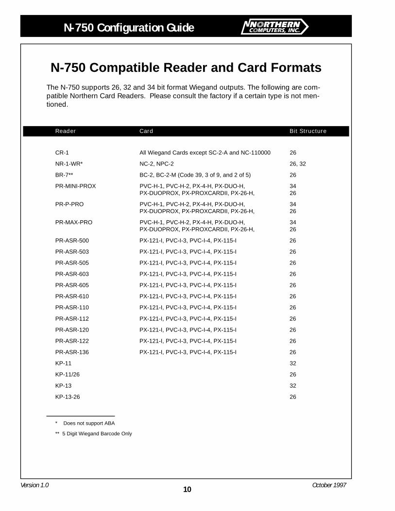
N-750 Compatible Reader and Card FormatsThe N-750 supports 26, 32 and 34 bit format Wiegand outputs. The following are com-patible Northern Card Readers. Please consult the factory if a certain type is not men-tioned.
Reader Card Bit Structure
CR-1 All Wiegand Cards except SC-2-A and NC-110000 26
NR-1-WR* NC-2, NPC-2 26, 32
BR-7** BC-2, BC-2-M (Code 39, 3 of 9, and 2 of 5) 26
PR-MINI-PROX PVC-H-1, PVC-H-2, PX-4-H, PX-DUO-H, 34PX-DUOPROX, PX-PROXCARDII, PX-26-H, 26
PR-P-PRO PVC-H-1, PVC-H-2, PX-4-H, PX-DUO-H, 34PX-DUOPROX, PX-PROXCARDII, PX-26-H, 26
PR-MAX-PRO PVC-H-1, PVC-H-2, PX-4-H, PX-DUO-H, 34PX-DUOPROX, PX-PROXCARDII, PX-26-H, 26
PR-ASR-500 PX-121-I, PVC-I-3, PVC-I-4, PX-115-I 26
PR-ASR-503 PX-121-I, PVC-I-3, PVC-I-4, PX-115-I 26
PR-ASR-505 PX-121-I, PVC-I-3, PVC-I-4, PX-115-I 26
PR-ASR-603 PX-121-I, PVC-I-3, PVC-I-4, PX-115-I 26
PR-ASR-605 PX-121-I, PVC-I-3, PVC-I-4, PX-115-I 26
PR-ASR-610 PX-121-I, PVC-I-3, PVC-I-4, PX-115-I 26
PR-ASR-110 PX-121-I, PVC-I-3, PVC-I-4, PX-115-I 26
PR-ASR-112 PX-121-I, PVC-I-3, PVC-I-4, PX-115-I 26
PR-ASR-120 PX-121-I, PVC-I-3, PVC-I-4, PX-115-I 26
PR-ASR-122 PX-121-I, PVC-I-3, PVC-I-4, PX-115-I 26
PR-ASR-136 PX-121-I, PVC-I-3, PVC-I-4, PX-115-I 26
KP-11 32
KP-11/26 26
KP-13 32
KP-13-26 26
* Does not support ABA
** 5 Digit Wiegand Barcode Only
N-750 Configuration Guide
11Version 1.0 October 1997
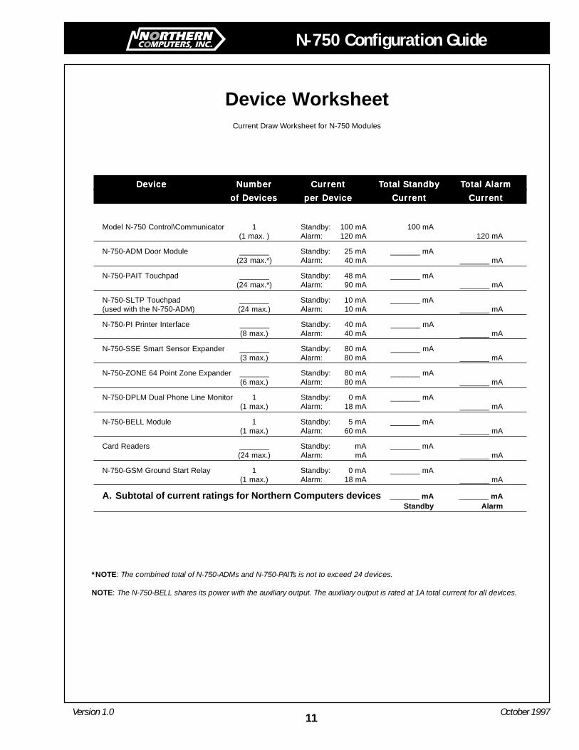
Device WorksheetCurrent Draw Worksheet for N-750 Modules
DeviceDeviceDeviceDeviceDevice NumberNumberNumberNumberNumber CurrentCurrentCurrentCurrentCurrent TTTTTotal Standbyotal Standbyotal Standbyotal Standbyotal Standby TTTTTotal Alarmotal Alarmotal Alarmotal Alarmotal Alarm
of Devicesof Devicesof Devicesof Devicesof Devices per Deviceper Deviceper Deviceper Deviceper Device CurrentCurrentCurrentCurrentCurrent CurrentCurrentCurrentCurrentCurrent
Model N-750 Control\Communicator 1 Standby: 100 mA 100 mA(1 max. ) Alarm: 120 mA 120 mA
N-750-ADM Door Module _______ Standby: 25 mA _______ mA(23 max.*) Alarm: 40 mA _______ mA
N-750-PAIT Touchpad _______ Standby: 48 mA _______ mA(24 max.*) Alarm: 90 mA _______ mA
N-750-SLTP Touchpad _______ Standby: 10 mA _______ mA(used with the N-750-ADM) (24 max.) Alarm: 10 mA _______ mA
N-750-PI Printer Interface _______ Standby: 40 mA _______ mA(8 max.) Alarm: 40 mA _______ mA
N-750-SSE Smart Sensor Expander _______ Standby: 80 mA _______ mA(3 max.) Alarm: 80 mA _______ mA
N-750-ZONE 64 Point Zone Expander _______ Standby: 80 mA _______ mA(6 max.) Alarm: 80 mA _______ mA
N-750-DPLM Dual Phone Line Monitor 1 Standby: 0 mA _______ mA(1 max.) Alarm: 18 mA _______ mA
N-750-BELL Module 1 Standby: 5 mA _______ mA(1 max.) Alarm: 60 mA _______ mA
Card Readers _______ Standby: mA _______ mA(24 max.) Alarm: mA _______ mA
N-750-GSM Ground Start Relay 1 Standby: 0 mA _______ mA(1 max.) Alarm: 18 mA _______ mA
A. Subtotal of current ratings for Northern Computers devices _______ mA _______ mAStandby Alarm
*NOTE: The combined total of N-750-ADMs and N-750-PAITs is not to exceed 24 devices.
NOTE: The N-750-BELL shares its power with the auxiliary output. The auxiliary output is rated at 1A total current for all devices.
12Version 1.0 October 1997
N-750 Configuration Guide
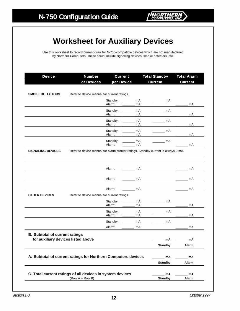
Worksheet for Auxiliary DevicesUse this worksheet to record current draw for N-750-compatible devices which are not manufactured
by Northern Computers. These could include signalling devices, smoke detectors, etc.
DeviceDeviceDeviceDeviceDevice NumberNumberNumberNumberNumber CurrentCurrentCurrentCurrentCurrent TTTTTotal Standbyotal Standbyotal Standbyotal Standbyotal Standby TTTTTotal Alarmotal Alarmotal Alarmotal Alarmotal Alarm
of Devicesof Devicesof Devicesof Devicesof Devices per Deviceper Deviceper Deviceper Deviceper Device CurrentCurrentCurrentCurrentCurrent CurrentCurrentCurrentCurrentCurrent
SMOKE DETECTORS Refer to device manual for current ratings.
Standby: _______ mA _______mAAlarm: _______ mA _______ mA
Standby: _______ mA _______ mAAlarm: _______ mA _______ mA
Standby: _______ mA _______ mAAlarm: _______ mA _______ mA
Standby: _______ mA _______ mAAlarm: _______ mA _______ mA
Standby: _______ mA _______ mAAlarm: _______ mA _______ mA
SIGNALING DEVICES Refer to device manual for alarm current ratings. Standby current is always 0 mA.
Alarm: _______ mA _______ mA
Alarm: _______ mA _______ mA
Alarm: _______ mA _______ mA
OTHER DEVICES Refer to device manual for current ratings.
Standby: _______ mA _______ mAAlarm: _______ mA _______ mA
Standby: _______ mA _______ mAAlarm: _______ mA _______ mA
Standby: _______ mA _______ mA
Alarm: _______ mA _______ mA
B. Subtotal of current ratingsfor auxiliary devices listed above _______ mA _______ mA
Standby Alarm
A. Subtotal of current ratings for Northern Computers devices _______ mA _______ mA
Standby Alarm
C. Total current ratings of all devices in system devices _______ mA _______ mA(Row A + Row B) Standby Alarm
N-750 Configuration Guide
13Version 1.0 October 1997
Glossary of Terms and DefinitionsN-750: The N-750 is a control/communicator for
use in residential and commercial security appli-cations, commercial and residential fire applica-tions. The N-750 includes a sophisticated accesscontrol system, through which you can monitorand control user access to specific areas of abuilding. Power: 18 VAC, 60 Hz, 50 VA, Temp: 32to 120 F (0 to 49 C), Dimensions: 15"W x 20"H x3"D, Weight 17lbs.
N-750-ACAS: The Access Control AdministrationSoftware (N-750-ACAS) enables you to managethe access control functions of the securitysystem. Used in conjunction with the N-750security system, you can use ACAS to manage adatabase of users and system events. Establishinga communication function enables system opera-tors to upload and store events from the controlpanel, form both on and off site locations. Thisinformation can then be used in generatingreports, which can be displayed and printed basedon event selection and sort criteria. N-750-ACASalso enables management of user and site infor-mation, such as access codes and security levels,user profiles, and time schedules.
N-750-ADM: The N-750-ADM is a card readerinterface for the N-750. The N-750-ADM can beused in conjunction with the N-750-PAIT for atotal combination of 24 devices. The N-750-ADMhas 2 SPDT relays for door lock and door heldopen and 2 contact inputs for door egress andstatus. The touchpad can also be used to programthe system in addition to arming and disarmingalarms.
N-750-APS: The N-750-APS is a notification andauxiliary power expander that provides up to 2.5amps of and 12 volt power for powering notifica-tion appliances and auxiliary devices. TheN-750-APS uses the N-750 snap track located inthe N-750 cabinet or the N-750-ENC accessoryenclosure.
N-750-APS-24: The N-750-APS-24 is a notificationand auxiliary power expander that provides up to6 amps of regulated, 24 volt power for poweringnotification appliances and auxiliary devices. TheN-750-APS-24 provides its own AC power connec-
tion, battery charging circuit, and battery connec-tions. Used with security and fire panels, the N-750-APS-24 enables you to connect and distributepower to many more devices than your panel maynormally allow.
N-750-BELL: The N-750-BELL module provides anoutput for a bell sounding device to annunciatealarms from the N-750 system.
N-750-BELL-SUP: The N-750-BELL-SUP providessupervision of the N-750-BELL and is required forUL applications.
N-750-COMM-CBL: The N-750-COMM-CBL is a 3'RJ31X cord for connecting a phone line to thebuilt in digital communicator on the N-750. Thecable can also be used when the N-750-DPLMdual phone line adapter is installed in the N-750.
N-750-DPLM: The N-750-DPLM provides a secondphone line connection. The N-750-DPLM includesa line monitor and ring detector for a second line.The N-750-DPLM is required for UL installations.The N-750-DPLM connects and mounts directly tothe standoffs provided on the panel. Power: 11 to14 VDC at 20 mA (active only), Temp: 32 to 120F (0 to 49 C), Dimensions: 2.175"W x 2.375"H x1.75"D (including mounts).
N-750-ENC: Standard N-750 size enclosure with an2 snap tracks. Snap tracks are used to mountaccessories such as the N-750-APS and N-750-SSE. Each enclosure can hold 4 accessories, aswell as 2 BAT-N-750s. Dimensions: 15"W x 20"H x3"D.
N-750-EOL-UL-10: The N-750-EOL-UL-10 is a 10pack of End-of-Line UL approved 4.7 k resistors.The N-750-EOL-UL-10 is used for all hardwireinput zones on the N-750. (The N-750-EOL-UL-10is not used with the N-750-SS, use the N-750-EOL-UL-SS).
N-750-EOL-UL-SS: The N-750-EOL-UL-SS End-of-Line resistors are a 10 pack of 1.43K ohm resistorsfor use with the N-750-SS. The N-750-EOL-UL-SSis required for UL applications.
14Version 1.0 October 1997
N-750 Configuration Guide
N-750-GSM: The N-750-GSM is for a ground starttelephone system, and consists of a ground startchip. Please note that a ground start modulecannot be used in UL applications.
N-750-INPT-CNCT: The N-750-INPT-CNCT is aconnector that plugs into the N-750-PAIT. Thisallows for the input zones and output relay of theN-750-PAIT to be connected. One unit comesstandard with each N-750-PAIT.
N-750-KOHP: The N-750-KOHP provide tamperproof hole plugs for the N-750 enclosure. The N-750-KOHP comes in a pack of 6 UL approvedknock out hole plugs.
N-750-PAIT: The N-750-PAIT is a commercialtouchpad that can be used as a door accessstation. The N-750-ADM can be used in conjunc-tion with the N-750-ADM for a total combinationof 24 devices. The N-750 system must have atleast one N-750-PAIT. The N-750-PAIT has 1SPDT relay for door lock and 2 contact inputs fordoor egress and status. The touchpad can also beused to program the system in addition to armingand disarming alarms and checking the status ofareas.
N-750-PI: The N-750-PI Serial/Parallel Moduleprovides one 9 pin RS-232 serial port and oneparallel printer port. Eight N-750-PIs can be usedper N-750. The N-750 can be used for eitherconnection to a PC directly using the CBL-N-750or in conjunction with an M-9600 and CBL-2 forremote communications.
N-750-RDR-CNCT: The N-750-RDR-CNCT is a 5wire Wiegand connector that plugs into the N-750-PAIT. This allows a Wiegand format reader tobe plugged directly into the N-750-PAIT. One unitcomes standard with each N-750-PAIT.
N-750-SK: The N-750-SK upload/download soft-ware is for programming the N-750 system by theinstalling dealer or central station. The softwareprograms partitions, zones, time windows, userlevels, system devices, and central station report-ing accounts. Only one copy is required perdealer. Each copy can support an unlimitednumber of panels.
N-750-SLTP: The N-750-SLTP is an indoor/outdoortouchpad with weather resistant housing. The N-750-SLTP can be used to arm/disarm an N-750system as well as used for door access as entryonly or in conjunction with a card reader for highsecurity with a combination card and pin number.The touchpad has “READY” and “Armed” lights,but there is no display screen. The N-750-SLTPmust be interfaced with the N-750-ADM. CurrentDraw: 10 mA, Temp: 32 to 120 F (0 to 49 C),Dimensions: 1.5"W x 6.37"H x .5"D.
N-750-SS: The N-750-SS SmartSensor is used inconjunction with the N-750-SSE. The N-750-SSconnects to serial loops on the N-750-SS control-ler module. N-750-SS SmartSensor point IDmodules allow connection to and point identifica-tion of, most security devices. SmartSensor pointID modules are addressed on-site using an N-750-PAIT.
N-750-SSE: The N-750-SSE Serial Zone Expander isa UL listed zone expansion system. The N-750-SSE is used in conjunction with the N-750-SSSmart Sensor. Each N-750 system can support atotal of 3 N-750-SSE expanders for a total of 384points, with 128 points per N-750-SSE. Each pointon the N-750-SSE is addressed with an N-750-SS.The N-750-SS does not have a built-in end-of-lineresistor, and the N-750-EOL-UL-SS resistor shouldbe used for all UL Smart Sensor applications.
N-750-TC: The N-750-TC transformer cover is a ULrated outlet cover for a standard duplex outlet.The N-750-TC is required for NFPA 71 and NFPA72A fire alarm installations to protect class 2transformer and power wiring to N-750 control.Knockouts provided for 3/4" conduit. Dimensions:3.625" W x 6.125"H x 2.5"D.
N-750-ZONE: The N-750-ZONE is a hardwireexpander that allows 64 zones to be added to theN-750 system. A total of six N-750-ZONE mod-ules can be added to the system (if no other zoneexpansion device is being used).
N-750 Configuration Guide
15Version 1.0 October 1997
NOTES:

Headquarters:5007 S. Howell Ave.Milwaukee, WI 53207 USA
Northern Computers, Inc.Leaders in Access Control Technology
Worldwide LocationsCanada United Kingdom Germany France Italy Russia Egypt Brazil Mexico Ecuador Argentina Hong Kong Australia Japan
Phone: (414) 769-5980Fax: (414) 769-5989
http://www.nciaccess.com